WO2017113403A1 - Image information processing method and augmented reality ar device - Google Patents
Image information processing method and augmented reality ar device Download PDFInfo
- Publication number
- WO2017113403A1 WO2017113403A1 PCT/CN2015/100331 CN2015100331W WO2017113403A1 WO 2017113403 A1 WO2017113403 A1 WO 2017113403A1 CN 2015100331 W CN2015100331 W CN 2015100331W WO 2017113403 A1 WO2017113403 A1 WO 2017113403A1
- Authority
- WO
- WIPO (PCT)
- Prior art keywords
- image
- point
- straight line
- projection
- distance
- Prior art date
Links
- 230000003190 augmentative effect Effects 0.000 title claims abstract description 17
- 230000010365 information processing Effects 0.000 title abstract description 13
- 238000003672 processing method Methods 0.000 title abstract description 13
- 238000000034 method Methods 0.000 claims abstract description 60
- 230000007613 environmental effect Effects 0.000 claims description 41
- 238000012545 processing Methods 0.000 claims description 17
- 239000000284 extract Substances 0.000 claims description 14
- 238000009966 trimming Methods 0.000 claims 1
- 230000033001 locomotion Effects 0.000 abstract description 4
- 238000004891 communication Methods 0.000 description 66
- 230000006870 function Effects 0.000 description 18
- 238000010586 diagram Methods 0.000 description 16
- 238000004422 calculation algorithm Methods 0.000 description 13
- 238000003860 storage Methods 0.000 description 13
- 230000005540 biological transmission Effects 0.000 description 11
- 230000001413 cellular effect Effects 0.000 description 10
- 230000008569 process Effects 0.000 description 10
- 238000005516 engineering process Methods 0.000 description 8
- 230000003287 optical effect Effects 0.000 description 8
- 238000001514 detection method Methods 0.000 description 6
- 230000004927 fusion Effects 0.000 description 6
- 230000002093 peripheral effect Effects 0.000 description 5
- 230000009286 beneficial effect Effects 0.000 description 4
- 239000000446 fuel Substances 0.000 description 4
- 230000007246 mechanism Effects 0.000 description 4
- 230000004044 response Effects 0.000 description 4
- 230000001133 acceleration Effects 0.000 description 3
- 238000013507 mapping Methods 0.000 description 3
- 230000000007 visual effect Effects 0.000 description 3
- LFQSCWFLJHTTHZ-UHFFFAOYSA-N Ethanol Chemical compound CCO LFQSCWFLJHTTHZ-UHFFFAOYSA-N 0.000 description 2
- XEEYBQQBJWHFJM-UHFFFAOYSA-N Iron Chemical compound [Fe] XEEYBQQBJWHFJM-UHFFFAOYSA-N 0.000 description 2
- ATUOYWHBWRKTHZ-UHFFFAOYSA-N Propane Chemical compound CCC ATUOYWHBWRKTHZ-UHFFFAOYSA-N 0.000 description 2
- 238000001069 Raman spectroscopy Methods 0.000 description 2
- 238000004590 computer program Methods 0.000 description 2
- 238000010276 construction Methods 0.000 description 2
- 239000003502 gasoline Substances 0.000 description 2
- 238000003384 imaging method Methods 0.000 description 2
- 239000000463 material Substances 0.000 description 2
- 238000005259 measurement Methods 0.000 description 2
- 230000006855 networking Effects 0.000 description 2
- 238000001228 spectrum Methods 0.000 description 2
- 238000012546 transfer Methods 0.000 description 2
- 241000410536 Esme Species 0.000 description 1
- DGAQECJNVWCQMB-PUAWFVPOSA-M Ilexoside XXIX Chemical compound C[C@@H]1CC[C@@]2(CC[C@@]3(C(=CC[C@H]4[C@]3(CC[C@@H]5[C@@]4(CC[C@@H](C5(C)C)OS(=O)(=O)[O-])C)C)[C@@H]2[C@]1(C)O)C)C(=O)O[C@H]6[C@@H]([C@H]([C@@H]([C@H](O6)CO)O)O)O.[Na+] DGAQECJNVWCQMB-PUAWFVPOSA-M 0.000 description 1
- HBBGRARXTFLTSG-UHFFFAOYSA-N Lithium ion Chemical compound [Li+] HBBGRARXTFLTSG-UHFFFAOYSA-N 0.000 description 1
- ZLMJMSJWJFRBEC-UHFFFAOYSA-N Potassium Chemical compound [K] ZLMJMSJWJFRBEC-UHFFFAOYSA-N 0.000 description 1
- 239000002253 acid Substances 0.000 description 1
- 230000004888 barrier function Effects 0.000 description 1
- -1 batteries Substances 0.000 description 1
- 230000003542 behavioural effect Effects 0.000 description 1
- 238000004364 calculation method Methods 0.000 description 1
- 239000003990 capacitor Substances 0.000 description 1
- 230000010267 cellular communication Effects 0.000 description 1
- 230000008859 change Effects 0.000 description 1
- 238000002485 combustion reaction Methods 0.000 description 1
- 230000000295 complement effect Effects 0.000 description 1
- 239000012141 concentrate Substances 0.000 description 1
- 239000000470 constituent Substances 0.000 description 1
- 230000008878 coupling Effects 0.000 description 1
- 238000010168 coupling process Methods 0.000 description 1
- 238000005859 coupling reaction Methods 0.000 description 1
- 238000005520 cutting process Methods 0.000 description 1
- 230000001419 dependent effect Effects 0.000 description 1
- 238000002405 diagnostic procedure Methods 0.000 description 1
- 230000009977 dual effect Effects 0.000 description 1
- 238000011156 evaluation Methods 0.000 description 1
- 239000000835 fiber Substances 0.000 description 1
- 230000005057 finger movement Effects 0.000 description 1
- 239000002828 fuel tank Substances 0.000 description 1
- 239000011521 glass Substances 0.000 description 1
- 238000009434 installation Methods 0.000 description 1
- 229910052742 iron Inorganic materials 0.000 description 1
- 229910001416 lithium ion Inorganic materials 0.000 description 1
- 230000007774 longterm Effects 0.000 description 1
- 238000004519 manufacturing process Methods 0.000 description 1
- 229910052751 metal Inorganic materials 0.000 description 1
- 239000002184 metal Substances 0.000 description 1
- 229910044991 metal oxide Inorganic materials 0.000 description 1
- 150000004706 metal oxides Chemical class 0.000 description 1
- 238000010295 mobile communication Methods 0.000 description 1
- 238000012544 monitoring process Methods 0.000 description 1
- 230000008520 organization Effects 0.000 description 1
- 239000003208 petroleum Substances 0.000 description 1
- 229910052700 potassium Inorganic materials 0.000 description 1
- 239000011591 potassium Substances 0.000 description 1
- 239000001294 propane Substances 0.000 description 1
- 230000008439 repair process Effects 0.000 description 1
- 238000011160 research Methods 0.000 description 1
- 239000004065 semiconductor Substances 0.000 description 1
- 229910052708 sodium Inorganic materials 0.000 description 1
- 239000011734 sodium Substances 0.000 description 1
- 230000003068 static effect Effects 0.000 description 1
- 238000010897 surface acoustic wave method Methods 0.000 description 1
Images


Classifications
-
- G—PHYSICS
- G02—OPTICS
- G02B—OPTICAL ELEMENTS, SYSTEMS OR APPARATUS
- G02B27/00—Optical systems or apparatus not provided for by any of the groups G02B1/00 - G02B26/00, G02B30/00
- G02B27/01—Head-up displays
-
- G—PHYSICS
- G06—COMPUTING; CALCULATING OR COUNTING
- G06T—IMAGE DATA PROCESSING OR GENERATION, IN GENERAL
- G06T7/00—Image analysis
- G06T7/70—Determining position or orientation of objects or cameras
- G06T7/73—Determining position or orientation of objects or cameras using feature-based methods
- G06T7/74—Determining position or orientation of objects or cameras using feature-based methods involving reference images or patches
-
- G—PHYSICS
- G06—COMPUTING; CALCULATING OR COUNTING
- G06V—IMAGE OR VIDEO RECOGNITION OR UNDERSTANDING
- G06V10/00—Arrangements for image or video recognition or understanding
- G06V10/20—Image preprocessing
- G06V10/26—Segmentation of patterns in the image field; Cutting or merging of image elements to establish the pattern region, e.g. clustering-based techniques; Detection of occlusion
-
- G—PHYSICS
- G06—COMPUTING; CALCULATING OR COUNTING
- G06V—IMAGE OR VIDEO RECOGNITION OR UNDERSTANDING
- G06V10/00—Arrangements for image or video recognition or understanding
- G06V10/40—Extraction of image or video features
- G06V10/44—Local feature extraction by analysis of parts of the pattern, e.g. by detecting edges, contours, loops, corners, strokes or intersections; Connectivity analysis, e.g. of connected components
-
- G—PHYSICS
- G06—COMPUTING; CALCULATING OR COUNTING
- G06V—IMAGE OR VIDEO RECOGNITION OR UNDERSTANDING
- G06V20/00—Scenes; Scene-specific elements
- G06V20/20—Scenes; Scene-specific elements in augmented reality scenes
-
- G—PHYSICS
- G06—COMPUTING; CALCULATING OR COUNTING
- G06V—IMAGE OR VIDEO RECOGNITION OR UNDERSTANDING
- G06V20/00—Scenes; Scene-specific elements
- G06V20/50—Context or environment of the image
- G06V20/56—Context or environment of the image exterior to a vehicle by using sensors mounted on the vehicle
-
- B—PERFORMING OPERATIONS; TRANSPORTING
- B60—VEHICLES IN GENERAL
- B60R—VEHICLES, VEHICLE FITTINGS, OR VEHICLE PARTS, NOT OTHERWISE PROVIDED FOR
- B60R2300/00—Details of viewing arrangements using cameras and displays, specially adapted for use in a vehicle
- B60R2300/20—Details of viewing arrangements using cameras and displays, specially adapted for use in a vehicle characterised by the type of display used
- B60R2300/205—Details of viewing arrangements using cameras and displays, specially adapted for use in a vehicle characterised by the type of display used using a head-up display
-
- B—PERFORMING OPERATIONS; TRANSPORTING
- B60—VEHICLES IN GENERAL
- B60R—VEHICLES, VEHICLE FITTINGS, OR VEHICLE PARTS, NOT OTHERWISE PROVIDED FOR
- B60R2300/00—Details of viewing arrangements using cameras and displays, specially adapted for use in a vehicle
- B60R2300/30—Details of viewing arrangements using cameras and displays, specially adapted for use in a vehicle characterised by the type of image processing
- B60R2300/307—Details of viewing arrangements using cameras and displays, specially adapted for use in a vehicle characterised by the type of image processing virtually distinguishing relevant parts of a scene from the background of the scene
- B60R2300/308—Details of viewing arrangements using cameras and displays, specially adapted for use in a vehicle characterised by the type of image processing virtually distinguishing relevant parts of a scene from the background of the scene by overlaying the real scene, e.g. through a head-up display on the windscreen
-
- G—PHYSICS
- G02—OPTICS
- G02B—OPTICAL ELEMENTS, SYSTEMS OR APPARATUS
- G02B27/00—Optical systems or apparatus not provided for by any of the groups G02B1/00 - G02B26/00, G02B30/00
- G02B27/01—Head-up displays
- G02B27/0101—Head-up displays characterised by optical features
- G02B2027/0138—Head-up displays characterised by optical features comprising image capture systems, e.g. camera
-
- G—PHYSICS
- G02—OPTICS
- G02B—OPTICAL ELEMENTS, SYSTEMS OR APPARATUS
- G02B27/00—Optical systems or apparatus not provided for by any of the groups G02B1/00 - G02B26/00, G02B30/00
- G02B27/01—Head-up displays
- G02B27/0101—Head-up displays characterised by optical features
- G02B2027/014—Head-up displays characterised by optical features comprising information/image processing systems
-
- G—PHYSICS
- G02—OPTICS
- G02B—OPTICAL ELEMENTS, SYSTEMS OR APPARATUS
- G02B27/00—Optical systems or apparatus not provided for by any of the groups G02B1/00 - G02B26/00, G02B30/00
- G02B27/01—Head-up displays
- G02B27/0101—Head-up displays characterised by optical features
- G02B2027/0141—Head-up displays characterised by optical features characterised by the informative content of the display
-
- G—PHYSICS
- G06—COMPUTING; CALCULATING OR COUNTING
- G06T—IMAGE DATA PROCESSING OR GENERATION, IN GENERAL
- G06T2207/00—Indexing scheme for image analysis or image enhancement
- G06T2207/30—Subject of image; Context of image processing
- G06T2207/30248—Vehicle exterior or interior
- G06T2207/30252—Vehicle exterior; Vicinity of vehicle
-
- G—PHYSICS
- G06—COMPUTING; CALCULATING OR COUNTING
- G06T—IMAGE DATA PROCESSING OR GENERATION, IN GENERAL
- G06T2207/00—Indexing scheme for image analysis or image enhancement
- G06T2207/30—Subject of image; Context of image processing
- G06T2207/30248—Vehicle exterior or interior
- G06T2207/30268—Vehicle interior
Definitions
- the present invention relates to the field of image processing technologies, and in particular, to an image information processing method and an augmented reality AR device.
- the inventor of the technical solution found in the research process that because the human eye has limited vision and is susceptible to internal and external factors such as fatigue driving and low environmental visibility, it is difficult for the driver to look at the target object in the line of sight by the eye alone.
- the driving dynamics are always clearly understood during driving and the driving safety is affected.
- the embodiment of the invention provides an image information processing method and an augmented reality AR device, which is beneficial to the driver to comprehensively and clearly obtain the environmental dynamics in the line of sight, thereby improving driving safety.
- a first aspect of the embodiments of the present invention discloses a method for processing image information, including:
- the augmented reality AR device acquires a first image including an image of the target object, wherein the AR device is disposed on a center console of the automobile, the target object is located in front of the automobile;
- the AR device detects an environmental parameter of the AR device based on the first image
- the AR device crops the first image to obtain a second image based on the cropping scale factor
- the AR device extracts M contour feature points in the remaining images of the target object in the second image to generate an AR image of the target object, where the M is a positive integer;
- the AR device displays the AR image on a front windshield of the automobile.
- the AR device can generate an augmented reality AR image of the target object, and the AR image displayed on the front windshield of the automobile enables the driver to comprehensively and clearly obtain the environmental dynamics in the line of sight, which is beneficial to improving driving safety.
- the driver is driving while driving at night.
- the AR device can quickly output an AR image conforming to the pedestrian (such as the image contour information of the pedestrian), and the AR image displayed on the front windshield of the car is beneficial to the driver to fully and clearly obtain the view within the line of sight.
- the AR device displays the AR image on a front windshield of the automobile, including:
- the AR device adds the AR image to the third image according to the position of the M contour feature points in the second image, where the third image is a blank image, and the size of the third image is The sizes of the second images are matched;
- the AR device projects the third image on the front windshield according to the projection angle.
- the AR device displays the AR image on a front windshield of the automobile, including:
- the AR device projects the AR image on the front windshield according to the projection angle.
- the front windshield includes a display screen
- the AR device displays the AR image on a front windshield of the automobile, including:
- the AR device displays the AR image on a display screen of a front windshield of the automobile based on the positions of the M projection points.
- the AR device acquisition includes The first image of the image of the target object, including:
- the AR device takes a ranging feature point on the target object as a focus reference point, and captures the target object to obtain a first image, wherein a pixel point corresponding to the focus reference point in the first image is the The focus of the first image.
- the AR device detects the environmental parameter of the AR device based on the first image.
- the AR device detects a distance c0 between the ranging feature point and a center point of the AR device based on a relative position of the focus in the first image in the first image, and determines a distance corresponding to the distance c0.
- the AR device captures a driver image to obtain a reference image, and detects a driver's human eye center point and the AR device center point based on a relative position of a driver's human eye center pixel in the reference image in the reference image. a first distance c1 between the first distance c1, and determine the angle between the line segment corresponding to the first distance c1 and the device view plane q1;
- the AR device detects an angle between a line segment corresponding to a second distance c2 between the feature point B' of the upper windshield and a center point of the AR device, and a second distance c2 and the device view plane Q2, and detecting an angle q3 between a line segment corresponding to a third distance c3 between the feature point C' of the lower edge of the windshield and the center point of the AR device, and the third distance c3 and the viewing plane of the device .
- the AR device determines, according to the environmental parameter, the first image Crop scale factor, including:
- the AR device indicates the center point of the AR device as the origin O of the two-dimensional coordinate system XOY, and indicates a straight line passing through the ranging feature point of the target object and perpendicular to the viewing plane of the device as a straight line.
- L based on the origin O and the straight line L, determining a reference plane of the two-dimensional coordinate system XOY, indicating a projection line of the device view plane on the reference plane as an X-axis, and the X-axis
- the direction is set to be away from the straight line L by the origin O;
- the AR device indicates a projection point of the driver's human eye center point on the reference plane as a point A in the two-dimensional coordinate system XOY, and a projection point of the feature point B′ on the reference plane as a point B.
- a projection point of the feature point C' on the reference plane is indicated as a point C
- a projection line of the driver's view plane on the reference plane is indicated as a straight line N;
- the projection of the point A on the X axis is a point A1
- the point B is cast on the straight line N
- the image is a point B1
- the projection of the point B on the X-axis is a point B2
- the projection of the origin O on the straight line L is a point O1
- the projection of the point A on the straight line L is Point A2
- the intersection of the line where the line segment OB is located and the line L is point C1
- the intersection of the line where the line segment AB is located and the line L is point C2
- the intersection of the line where the line segment OC is located and the line L is point C3 ;
- the AR device equalizes the length of the line segment OA to the first distance c1, the ⁇ AOA1 to the angle q1, and the length of the line segment OB to the distance c2, which will be BOO1 is equivalent to the angle q2, the length of the line segment OC is equivalent to the distance c3, and the ⁇ COO1 is equivalent to the angle q3;
- a second aspect of an embodiment of the present invention discloses an AR device, the AR device including a memory, and a processor coupled to the memory.
- the memory is for storing instructions
- the processor is configured to execute the instructions to perform some or all of the steps described in any of the methods of the first aspect of the embodiments of the present invention.
- a third aspect of embodiments of the present invention discloses a computer readable storage medium, wherein the computer readable storage medium stores program code for execution by an AR device, the program code specifically including instructions for executing the present Some or all of the steps described in any of the methods of the first aspect of the invention.
- the fourth aspect of the embodiments of the present invention discloses an AR device, where the AR device includes a functional unit, and the functional unit is used to perform some or all of the steps described in any one of the first aspects of the embodiments of the present invention.
- the AR device may further perform the following operations:
- the AR device acquires association information of the target object, and displays the association information at a first preset position of the front windshield of the automobile, where the association information includes at least identity information of the target object, Type information; or,
- the AR device acquires navigation information associated with the target object, and displays the associated information at a second preset position of the front windshield of the automobile.
- the target object may include various types of objects or pedestrians that may appear in the driver's line of sight during driving, such as road signs, buildings, cars, barriers, and the like.
- the AR device first acquires a first image including an image of the target object, and detects an environmental parameter of the AR device based on the first image, and secondly, the AR device determines a cutting ratio coefficient of the first image based on the environmental parameter, and again The AR device crops the first image to obtain a second image based on the cropping scale coefficient, and the AR device then extracts M contour feature points in the remaining images of the target object in the second image to generate an AR image of the target object, and finally, the AR The device displays an AR image on the front windshield of the car.
- the AR device provided by the embodiment of the present invention can generate an augmented reality AR image of the target object and display the generated AR image on the front windshield of the automobile, thereby facilitating the driver to comprehensively and clearly obtain the environmental dynamics in the line of sight, thereby Improve driving safety.
- FIG. 1 is a system architecture diagram of a mobile vehicle communication system according to an embodiment of the present invention.
- FIG. 1.1 is a functional block diagram of an example vehicle 100 according to an embodiment of the present invention.
- FIG. 1.2 is a schematic diagram of an application scenario of an AR device according to an embodiment of the present disclosure.
- FIG. 2 is a schematic structural diagram of an AR device 100 according to an embodiment of the present invention.
- FIG. 3 is a schematic diagram of a method for processing image information according to a first method embodiment of the present invention
- FIG. 4 is a second embodiment of the method of the present invention discloses a method for processing image information
- FIG. 4.1 is a schematic diagram of an equivalent two-dimensional coordinate system XOY of an exemplary application scenario disclosed in an embodiment of the present invention.
- FIG. 4.2 is a schematic diagram of a feature point on a target object corresponding to a contour feature point in a two-dimensional coordinate system XOY according to an embodiment of the present invention
- FIG. 5 is a schematic diagram of a method for processing image information according to a third method embodiment of the present invention.
- FIG. 6 is a method for processing image information according to a fourth method embodiment of the present invention.
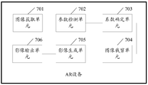
- FIG. 7 is a simplified functional block diagram of an AR device disclosed in an embodiment of the apparatus of the present invention.
- FIG. 1 is a system architecture diagram of a mobile vehicle communication system according to an embodiment of the present invention.
- the communication system 10 includes a vehicle 12, one or more wireless carrier systems 14, and a ground.
- the surface communication network 16, the computer 18, and the call center 20 are not specifically limited to the operating environments shown herein.
- the architecture, construction, setup, and operation of system 10, as well as its individual components, are generally known in the art. Thus, the following paragraphs simply provide an overview of an example communication system 10, and other systems not shown herein can also use the disclosed methods.
- the vehicle 12 can be implemented on a car or in the form of a car.
- the example system can also be implemented on other vehicles or in the form of other vehicles, such as cars, trucks, motorcycles, buses, boats, airplanes, helicopters, lawn mowers, snow shovels, recreational vehicles, amusement park vehicles.
- Other equipment such as agricultural equipment, construction equipment, trams, golf carts, trains and trams.
- the robotic device can also be used to perform the methods and systems described herein.
- vehicle electronics 28 include an information communication unit 30, a microphone 32, one or more buttons or other control inputs 34, an audio system 36, a visual display 38, and a GPS (Global Position System, global).
- a positioning system) module 40 and a plurality of VSMs (Vehicle Security Modules) 42 are provided. Some of these devices can be directly connected to an information communication unit, such as microphone 32 and button 34, while others use one or more network connections to make an indirect connection, such as communication bus 44 or entertainment bus 46.
- Suitable network connections include CAN (Controller Area Network), MOST (Media Oriented Systems Transport), LIN (Local Interconnect Network), LAN (Local Area Network) And other suitable connections, such as Ethernet or conforming to the known ISO (International Organization for Standardization), SAE (Society of Automotive Engineers), and IEEE (Institute of Electrical and Electronics Engineers, International) The Institute of Electrical and Electronics Engineers) other connections to standards and regulations, just to name a few.
- the information communication unit 30 may be an OEM (Original Equipment Manufacturer) installation (embedded) or accessory market device installed in the vehicle and capable of wirelessly sounding and/or wirelessly on the wireless carrier system 14 and/or Or data communication. This enables the vehicle to communicate with the call center 20, other information-enabled vehicles, or some other entity or device.
- the information communication unit preferably uses radio broadcasts to establish a communication channel with the wireless carrier system 14. (A voice channel and/or a data channel) enabling sound and/or data transmission to be transmitted and received on the channel.
- the messaging unit 30 enables the vehicle to provide a variety of different services, including those associated with navigation, telephony, emergency, diagnostics, infotainment, and the like.
- Data can be transmitted over a data connection (e.g., via packet data over a data channel, or via a voice channel using techniques known in the art).
- voice communication e.g., having a live advisor live advisor or voice response unit at call center 20
- data communication e.g, providing GPS location data or vehicle diagnostic data to call center 20
- SMS short message service
- SMS can be used to send and receive data (eg, PDP (Packet Data Protocol); the information communication unit can be configured to be mobile terminated and/or initiated, or configured to terminate and/or apply. initiate.
- the information communication unit 30 utilizes cellular communication according to GSM (Global System for Mobile Communication) or CDMA (Code Division Multiple Access) standards, and thus includes standards for voice communication (for example, hands-free calling).
- GSM Global System for Mobile Communication
- CDMA Code Division Multiple Access
- the modem can be implemented by software stored in the information communication unit and executed by the processor 52, or it can be a separate hardware component located inside or outside the information communication unit 30.
- the modem can use any number of different standards or protocols (eg EVDO (CDMA2000 1xEV-DO, EVDO), CDMA, GPRS (General Packet Radio Service) and EDGE (Enhanced Data Rate for GSM Evolution) GSM evolution technology)) to run.
- Wireless networking between the vehicle and other networked devices can also be performed using the information communication unit 30.
- the information communication unit 30 can be configured to wirelessly communicate according to one or more wireless protocols (eg, IEEE 802.11 protocol, WiMAX (Worldwide Interoperability for Microwave Access), or Bluetooth) .
- the information communication unit can be configured to have a static IP address, or can be set to be from the network.
- Another device such as a router or automatically receives the assigned IP address from a network address server.
- the processor 52 can be any type of device capable of processing electronic instructions, including a microprocessor, a microcontroller, a host processor, a controller, a vehicle communication processor, and an ASIC (Application Specific Integrated Circuit). . It can be a dedicated processor for the information communication unit 30 only or can be shared with other vehicle systems. Processor 52 executes various types of digital storage instructions, such as software or firmware programs stored in memory 54, which enables the information communication unit to provide a wide variety of services. For example, processor 52 can execute a program or process data to perform at least a portion of the methods discussed herein.
- the information communication unit 30 can be used to provide a range of vehicle services, including wireless communication to and/or from a vehicle.
- vehicle services include: turn-by-turn direct 1ns and other navigation-related services provided in conjunction with the GPS-based vehicle navigation module 40; airbag deployment notifications and interface modules with one or more collision sensors (eg, subjects) Control module (not shown) in combination with other emergency or roadside assistance associated services; diagnostic reports using one or more diagnostic modules; and infotainment related services, including music, web pages, movies, TV shows The video game and/or other information is downloaded by the infotainment module and stored for current or later playback.
- modules can be implemented in the form of software instructions stored inside or outside of the information communication unit 30, which may be hardware components located inside or outside the information communication unit 30, or they may be integrated with each other. / or shared, or integrated and / or shared with other systems located throughout the vehicle, just to name a few possibilities.
- the modules are implemented as VSMs 42 located external to the information communication unit 30, they may utilize the vehicle bus 44 to exchange data and commands with the information communication unit.
- the GPS module 40 receives radio signals from the constellation 60 of the GPS satellites. From these signals, the module 40 is able to determine the location of the vehicle that is used to provide the vehicle driver with navigation and other location-associated services.
- the navigation information can be presented on display 38 (or other display within the vehicle) or can be rendered in a language, such as when providing steering navigation.
- a navigation module (which may be part of the GPS module 40) within the dedicated vehicle can be used to provide navigation services, or some or all of the navigation services can be completed via the information communication unit 30, where the location information is sent to a remote location to facilitate Provide navigation maps, map annotations for vehicles (points of interest, Restaurants, etc.), route calculations, etc.
- the location information can be provided to call center 20 or other remote computer system, such as computer 18, for other purposes, such as fleet management. And, new or updated map data can be downloaded from the call center 20 to the GPS module 40 via the information communication unit 30.
- the vehicle 12 can include other vehicle system modules VSM 42 in the form of electronic hardware components that are located throughout the vehicle, typically receiving input from one or more sensors, The sensed inputs are used to perform diagnostics, monitoring, control, reporting, and/or other functions.
- VSMs 42 are preferably connected to other VSMs via a communication bus 44, also to the information communication unit 30, and can be programmed to run vehicle system and subsystem diagnostic tests.
- one VSM 42 can be an ECM (Engine Control Module) that controls various aspects of engine operation (eg, fuel ignition and ignition timing), and the other VSM 42 can be one or more that regulates the powertrain of the vehicle.
- ECM Engine Control Module
- the operating powertrain control module of the component, and the other VSM 42 can be a body control module that manages various electrical components (like the electric door lock and headlights of the vehicle) located throughout the vehicle.
- the engine control module is equipped with an OBD (On Board Diagnostics) feature that provides a large amount of real-time data, such as data received from various sensors (including vehicle emission sensors), and provides a standardized series. Diagnostic Trouble Code (DTS), which diagnoses fault codes allows technicians to quickly identify and repair faults within the vehicle.
- OBD On Board Diagnostics
- DTS Diagnostic Trouble Code
- the VSMs mentioned above are merely examples of some of the modules that may be used within the vehicle 12, and many other modules are also possible.
- the vehicle electronics 28 also includes a plurality of vehicle user interfaces that provide vehicle occupants with means for providing and/or receiving information, including a microphone 32, buttons 34, an audio system 36, and a visual display 38.
- vehicle user interface broadly includes any suitable form of electronic device, including hardware and software components that are located on a vehicle and that enable the vehicle user to communicate with components of the vehicle. Or communicate through the components of the vehicle.
- the microphone 32 provides an audio input to the information communication unit to enable the driver or other occupant to provide voice commands and perform an hands-free escort via the wireless carrier system 14. For this purpose, it can be connected to an in-vehicle automated sound processing unit that utilizes HMI (Human Machine Interface) technology known in the art.
- HMI Human Machine Interface
- the communication unit 30 is to initiate a wireless telephone call and provide other data, response or control inputs. Separate buttons can be used to initiate an emergency call as well as a regular service call to call center 20.
- the audio system 36 provides audio output to the vehicle occupant and can be a dedicated stand-alone system or part of the host vehicle audio system. In accordance with the particular embodiment illustrated herein, audio system 36 is operatively coupled to vehicle bus 44 and entertainment bus 46, and is capable of providing AM (Amplitude Modulation), FM (Frequency Modulation), and satellite broadcast, DVD. (Digital Versatile Disc) and other multimedia features. This functionality can be provided in conjunction with or separately from the infotainment module described above.
- Visual display 38 is preferably a graphical display, such as a touch screen on a dashboard or a heads-up display that is reflected from a windshield, and can be used to provide a variety of input and output functions.
- a graphical display such as a touch screen on a dashboard or a heads-up display that is reflected from a windshield
- Various other vehicle user interfaces can also be utilized, as the interface in Figure 1 is merely an example of a particular implementation.
- the wireless carrier system 14 is preferably a cellular telephone system comprising a plurality of cellular towers 70 (only one shown), one or more MSCs (Mobile Switching Centers) 72, and a wireless carrier system 14 coupled to the terrestrial network 16. Any other networking components required.
- Each of the cellular towers 70 includes transmit and receive antennas and base stations, and base stations from different cellular towers are directly connected to the MSC 72 or to the MSC 72 via intermediate devices (e.g., base station controllers).
- Cellular system 14 may implement any suitable communication technology including, for example, analog technologies (e.g., AMPS (Advanced Mobile Phone System)) or newer digital technologies (e.g., CDMA (e.g., CDMA2000) or GSM/GPRS).
- each base station and the cellular tower can be co-located at the same location, or they can be located farther from each other, each base station can respond to a single cellular tower or a single base station can serve each cellular tower, and each base station can be coupled to a single MSC, which is merely an example Give a small set of possible settings.
- different wireless carrier systems in the form of satellite communications can be used to provide one-way or two-way communication with the vehicle. This can be done using one or more communication satellites 62 and an uplink transmitting station 64.
- the one-way communication can be, for example, a satellite broadcast service in which program content (news, music, etc.) is received by the transmitting station 64, packaged for uploading, and then transmitted to the satellite 62, which broadcasts the program to the user.
- Two-way communication can be, for example, using satellite 62 at vehicle 12 and station 64 satellite telephone service for relay telephone communication between 64. If used, such a satellite phone can be attached to or used in place of the wireless carrier system 14.
- the terrestrial network 16 may be a conventional land-based radio communication network that is coupled to one or more fixed telephones and that connects the wireless carrier system 14 to the call center 20.
- terrestrial network 16 may include a PSTN (Public Switched Telephone Network), such as a PSTN that is used to provide wired telephone, packet switched data communications, and Internet infrastructure.
- PSTN Public Switched Telephone Network
- One or more portions of terrestrial network 16 can utilize standard wired networks, fiber optic or other optical networks, cable networks, power lines, other wireless networks (such as WLAN (Wireless Local Area Networks), or provide BWA (Broadband) Wireless Access, broadband wireless access) networks and any combination of them to implement.
- WLAN Wireless Local Area Networks
- BWA Broadband
- the terrestrial network 16 may also include one or more SMSCs (Short Message Service Centers) for storing, uploading, converting, and/or transmitting SMS (Short Message Service) between the sender and the receiver. ).
- SMSC Short Message Service Centers
- the SMSC can receive an SMS message from the call center 20 or a content provider (eg, an external short message entity or ESME), and the SMSC can transmit the SMS message to the vehicle 12 (eg, a mobile terminal device). SMSCs and their functions are known to the skilled person.
- call center 20 need not be connected via terrestrial network 16, but may include a wireless telephone device such that it can communicate directly with a wireless network (e.g., wireless carrier system 14).
- Computer 18 can be one of a plurality of computers that are accessible via a private or public network, such as the Internet. Each such computer 18 can be used for one or more purposes, such as a vehicle that can access a web server via the information communication unit 30 and the wireless carrier 14. Other such accessible computers 18 can be, for example, a service center computer in which diagnostic information and other vehicle data can be uploaded from the vehicle via the information communication unit 30; the vehicle owner or other user is a client for use, for example, for the following purposes Computer: accessing or receiving vehicle data, or setting or configuring user parameters, or controlling the functionality of the vehicle; or third party library, whether by communicating with the vehicle 12 or the call center 20, or communicating with both, vehicle data Or other information is provided to or from the third party library.
- a service center computer in which diagnostic information and other vehicle data can be uploaded from the vehicle via the information communication unit 30
- the vehicle owner or other user is a client for use, for example, for the following purposes Computer: accessing or receiving vehicle data, or setting or configuring user parameters, or controlling the functionality of
- the computer 18 can also be used to provide an Internet connection, such as a DNS (Domain Name Server) service, or as an IP using a DHCP (Dynamic Host Configuration Protocol) or other suitable protocol.
- DNS Domain Name Server
- DHCP Dynamic Host Configuration Protocol
- the address is given to the network address server of the vehicle 12.
- the call center 20 is designed to provide a variety of different system backend functions to the vehicle electronics 28, and according to the exemplary embodiment shown herein, the call center 20 typically includes one or more switches 80, servers 82, databases 84. On-site consultant 86, and VRS (Automatic voice response system) 88, all of which are known in the prior art. These various call center components are preferably coupled to each other via a wired or wireless local area network 90.
- Switch 80 can be a PBX (Private Branch Exchange) that routes incoming signals such that voice transmissions are typically sent to field consultant 86 via a regular telephone or to automated voice response system 88 using VoIP.
- the on-site consultant phone can also use VoIP (Voice over Internet Phone), as indicated by the dotted line in FIG.
- VoIP and other data communications through switch 80 are implemented via a modem (not shown) connected between switch 80 and network 90.
- Data transfer is passed to server 82 and/or database 84 via a modem.
- the database 84 is capable of storing account information such as user authentication information, vehicle identifiers, data profile records, behavioral patterns, and other related user information.
- Data transmission can also be performed by a wireless system, such as 802.1lx, GPRS, and the like.
- SMS short message service
- PDP public data packet data
- call center 20 can be configured to terminate and/or initiate mobile, or configured to terminate and/or initiate applications.
- the call center can instead use VRS 88 as an automated consultant, or VRS 88 and on-site consultants.
- a combination of 86 can be used.
- FIG. 1.1 is a functional block diagram of an exemplary vehicle 100 according to an embodiment of the present invention.
- Components coupled to or included in vehicle 100 may include propulsion system 102, sensor system 104, control system 106, peripherals 108, power source 110, computing device 111, and user interface 112.
- Computing device 111 can include a processor 113 and a memory 114.
- Computing device 111 may be part of a controller or controller of vehicle 100.
- the memory 114 can include instructions 115 that the processor 113 can run, and can also store map data 116.
- the components of the vehicle 100 can be configured to operate in a manner interconnected with each other and/or with other components coupled to the various systems.
- power source 110 can provide power to all components of vehicle 100.
- Computing device 111 can be configured to receive data from, and control, propulsion system 102, sensor system 104, control system 106, and peripherals 108.
- Computing device 111 can be configured to be at a user interface A display of the image is generated on 112 and an input is received from user interface 112.
- vehicle 100 may include more, fewer, or different systems, and each system may include more, fewer, or different components.
- the systems and components shown may be combined or divided in any number of ways.
- the propulsion system 102 can be used to provide power motion to the vehicle 100.
- the propulsion system 102 includes an engine/engine 118, an energy source 120, a transmission 122, and a wheel/tire 124.
- Engine/engine 118 may be or include any combination of internal combustion engine, electric motor, steam engine, and Stirling engine. Other engines and engines are also possible.
- propulsion system 102 can include multiple types of engines and/or engines.
- a gas-electric hybrid car may include a gasoline engine and an electric motor. Other examples are possible.
- Energy source 120 may be a source of energy that is fully or partially powered to engine/engine 118. That is, the engine/engine 118 can be used to convert the energy source 120 to mechanical energy. Examples of energy source 120 include gasoline, diesel, other petroleum-based fuels, propane, other compressed gas based fuels, ethanol, solar panels, batteries, and other sources of electrical power. The energy source(s) 120 may additionally or alternatively include any combination of fuel tanks, batteries, capacitors, and/or flywheels. In some examples, energy source 120 may also provide energy to other systems of vehicle 100.
- Transmission 122 can be used to transfer mechanical power from engine/engine 118 to wheel/tire 124.
- the transmission 122 can include a gearbox, a clutch, a differential, a drive shaft, and/or other components.
- the drive shaft includes one or more shafts for coupling to the wheel/tire 124.
- the wheel/tire 124 of the vehicle 100 can be configured in a variety of forms, including a single wheeled vehicle, a bicycle/motorcycle, a tricycle, or a car/truck four wheel form. Other wheel/tire forms are also possible, such as those that include six or more wheels.
- the wheel/tire 124 of the vehicle 100 can be configured to rotate differentially relative to the other wheels/tires 124.
- the wheel/tire 124 can include at least one wheel that is fixedly attached to the transmission 122 and at least one tire that is coupled to the driving surface and that is coupled to the edge of the wheel.
- Wheel/tire 124 may comprise any combination of metal and rubber, or a combination of other materials.
- Propulsion system 102 may additionally or alternatively include components in addition to those shown.
- Sensor system 104 may include several for sensing information about the environment in which vehicle 100 is located Sensors. As shown, the sensors of the sensor system include a GPS 126, an IMU (Inertial Measurement Unit) 128, a Radio Detection and Radar Ranging (RADAR) unit 130, a Laser Ranging (LIDAR) unit 132, a camera 134, and Actuator 136 to modify the position and/or orientation of the sensor. Sensor system 104 may also include additional sensors including, for example, sensors that monitor the internal systems of vehicle 100 (eg, O2 monitors, fuel gauges, oil temperatures, etc.). Sensor system 104 may also include other sensors.
- IMU Inertial Measurement Unit
- RADAR Radio Detection and Radar Ranging
- LIDAR Laser Ranging
- Actuator 136 to modify the position and/or orientation of the sensor.
- Sensor system 104 may also include additional sensors including, for example, sensors that monitor the internal systems of vehicle 100 (eg, O2 monitors, fuel gauges, oil temperatures,
- the GPS module 126 can be any sensor for estimating the geographic location of the vehicle 100.
- the GPS module 126 may include a transceiver that estimates the position of the vehicle 100 relative to the earth based on satellite positioning data.
- computing device 111 can be used in conjunction with map data 116 to use GPS module 126 to estimate the location of a lane boundary on a road on which vehicle 100 can travel.
- the GPS module 126 can take other forms as well.
- the IMU 128 may be used to sense changes in position and orientation of the vehicle 100 based on inertial acceleration and any combination thereof.
- the combination of sensors can include, for example, an accelerometer and a gyroscope. Other combinations of sensors are also possible.
- the RADAR unit 130 can be viewed as an object detection system for detecting the characteristics of an object using radio waves, such as the distance, height, direction or speed of the object.
- the RADAR unit 130 can be configured to transmit radio waves or microwave pulses that can bounce off any object in the course of the wave.
- the object may return a portion of the energy of the wave to a receiver (eg, a dish or antenna), which may also be part of the RADAR unit 130.
- the RADAR unit 130 can also be configured to perform digital signal processing on the received signal (bounce from the object) and can be configured to identify the object.
- LIDAR Light Detection and Ranging
- the LIDAR unit 132 includes a sensor that uses light to sense or detect objects in the environment in which the vehicle 100 is located.
- LIDAR is an optical remote sensing technique that can measure the distance to a target or other attribute of a target by illuminating the target with light.
- LIDAR unit 132 can include a laser source and/or a laser scanner configured to emit laser pulses, and a detector for receiving reflections of the laser pulses.
- the LIDAR unit 132 can include a laser range finder that is reflected by a rotating mirror and scans the laser around the digitized scene in one or two dimensions to acquire distance measurements at specified angular intervals.
- the LIDAR unit 132 can include components such as light (eg, laser) sources, scanners and optical systems, photodetectors, and receiver electronics, as well as position and navigation systems.
- the LIDAR unit 132 can be configured to image an object using ultraviolet (UV), visible, or infrared light, and can be used for a wide range of targets, including non-metallic objects.
- a narrow laser beam can be used to map physical features of an object with high resolution.
- wavelengths in the range of from about 10 microns (infrared) to about 250 nanometers (UV) can be used.
- Light is typically reflected via backscattering.
- Different types of scattering are used for different LIDAR applications such as Rayleigh scattering, Mie scattering and Raman scattering, and fluorescence.
- LIDAR can thus be referred to as Rayleigh laser RADAR, Mie LIDAR, Raman LIDAR, and sodium/iron/potassium fluorescent LIDAR.
- Appropriate combinations of wavelengths may allow remote mapping of objects, for example by looking for wavelength dependent changes in the intensity of the reflected signal.
- Three-dimensional (3D) imaging can be achieved using both a scanned LIDAR system and a non-scanning LIDAR system.
- "3D gated viewing laser radar” is an example of a non-scanning laser ranging system that uses a pulsed laser and a fast gating camera.
- the imaging LIDAR can also use a high-speed detector array that is typically built on a single chip using CMOS (Complementary Metal Oxide Semiconductor) and CCD (Charge Coupled Device) manufacturing techniques. And modulating the sensitive detector array to perform.
- CMOS Complementary Metal Oxide Semiconductor
- CCD Charge Coupled Device
- each pixel can be locally processed by high speed demodulation or gating such that the array can be processed to represent an image from the camera.
- thousands of pixels can be acquired simultaneously to create a 3D point cloud representing the object or scene detected by the LIDAR unit 132.
- a point cloud can include a set of vertices in a 3D coordinate system. These vertices may be defined, for example, by X, Y, Z coordinates and may represent the outer surface of the object.
- the LIDAR unit 132 can be configured to create a point cloud by measuring a large number of points on the surface of the object, and can output the point cloud as a data file. As a result of the 3D scanning process of the object through the LIDAR unit 132, the point cloud can be used to identify and visualize the object.
- the point cloud can be rendered directly to visualize the object.
- a point cloud may be converted to a polygonal or triangular mesh model by a process that may be referred to as surface reconstruction.
- Example techniques for converting a point cloud to a 3D surface may include a Delaunay triangulation, an alpha shape, and a rotating sphere. These techniques include building a network of triangles on existing vertices of a point cloud. Other example techniques may include points The cloud is converted to a volumetric distance field, and the implicit surface thus defined is reconstructed by a moving cube algorithm.
- Camera 134 can be used to capture any camera (eg, a still camera, video camera, etc.) of an image of the environment in which vehicle 100 is located. To this end, the camera can be configured to detect visible light, or can be configured to detect light from other portions of the spectrum, such as infrared or ultraviolet light. Other types of cameras are also possible. Camera 134 can be a two-dimensional detector or can have a three-dimensional spatial extent. In some examples, camera 134 can be, for example, a distance detector configured to generate a two-dimensional image indicative of the distance from camera 134 to several points in the environment. To this end, camera 134 can use one or more distance detection techniques.
- a distance detector configured to generate a two-dimensional image indicative of the distance from camera 134 to several points in the environment. To this end, camera 134 can use one or more distance detection techniques.
- camera 134 can be configured to use structured light technology in which vehicle 100 illuminates an object in the environment with a predetermined light pattern, such as a grid or checkerboard pattern, and uses camera 134 to detect reflections from predetermined light patterns of the object. . Based on the distortion in the reflected light pattern, the vehicle 100 can be configured to detect the distance of a point on the object.
- the predetermined light pattern may include infrared light or light of other wavelengths.
- Actuator 136 can be configured, for example, to modify the position and/or orientation of the sensor.
- Sensor system 104 may additionally or alternatively include components in addition to those shown.
- Control system 106 can be configured to control the operation of vehicle 100 and its components. To this end, control system 106 can include steering unit 138, throttle 140, braking unit 142, sensor fusion algorithm 144, computer vision system 146, navigation or routing system 148, and obstacle avoidance system 150.
- Steering unit 138 may be any combination of mechanisms configured to adjust the direction or direction of advancement of vehicle 100.
- the throttle 140 may be any combination of mechanisms configured to control the operating speed and acceleration of the engine/engine 118 and thereby control the speed and acceleration of the vehicle 100.
- Brake unit 142 may be any combination of mechanisms configured to decelerate vehicle 100.
- the brake unit 142 can use friction to slow the wheel/tire 124.
- the braking unit 142 can be configured to regeneratively convert the kinetic energy of the wheel/tire 124 into a current.
- Brake unit 142 can take other forms as well.
- Sensor fusion algorithm 144 may include, for example, an algorithm (or a computer program product that stores the algorithm) that computing device 111 may operate. Sensor fusion algorithm 144 can be configured to accept data from sensor 104 as an input. The data may include, for example, data representing information sensed at the sensors of sensor system 104. Sensor fusion algorithm 144 may include, for example, a Kalman filter, a Bayesian network, or Additional algorithms. Sensor fusion algorithm 144 may also be configured to provide various ratings based on data from sensor system 104, including, for example, an assessment of individual objects and/or features in the environment in which vehicle 100 is located, an assessment of a particular situation, and/or An assessment based on the likely impact of a particular situation. Other evaluations are also possible.
- Computer vision system 146 may be any system configured to process and analyze images captured by camera 134 to identify objects and/or features in the environment in which vehicle 100 is located, such as lane information, traffic, for example Signals and obstacles. To this end, computer vision system 146 may use object recognition algorithms, Structure from Motion (SFM) algorithms, video tracking, or other computer vision techniques. In some examples, computer vision system 146 may additionally be configured as a mapping environment, following an object, estimating the speed of an object, and the like.
- SFM Structure from Motion
- the navigation and route control system 148 can be any system configured to determine the driving route of the vehicle 100.
- the navigation and route control system 148 can additionally be configured to dynamically update the driving route while the vehicle 100 is in operation.
- navigation and route control system 148 can be configured to combine data from sensor fusion algorithm 144, GPS module 126, and one or more predetermined maps to determine a driving route for vehicle 100.
- the obstacle avoidance system 150 can be any system configured to identify, evaluate, and avoid or otherwise cross obstacles in the environment in which the vehicle 100 is located.
- Control system 106 may additionally or alternatively include components in addition to those shown.
- Peripheral device 108 can be configured to allow vehicle 100 to interact with external sensors, other vehicles, and/or users.
- peripheral device 108 can include, for example, wireless communication system 152, touch screen 154, microphone 156, and/or speaker 158.
- Wireless communication system 152 can be any system configured to be wirelessly coupled to one or more other vehicles, sensors, or other entities, either directly or via a communication network.
- the wireless communication system 152 can include an antenna and chipset for communicating with other vehicles, sensors, or other entities, either directly or through an air interface.
- the chipset or the entire wireless communication system 152 can be arranged to communicate in accordance with one or more other types of wireless communications (e.g., protocols) such as those described in Bluetooth, IEEE 802.11 (including any IEEE 802.11 revision).
- Wireless communication system 152 can take other forms as well.
- cellular technologies such as GSM, CDMA, UMTS (Universal Mobile Telecommunications System), EV-DO, WiMAX or LTE (Long Term Evolution), Zigbee, DSRC (Dedicated Short Range Communications), and RFID (Radio Frequency Identification) communication, and the like.
- Wireless communication system 152 can take other forms as well.
- Touch screen 154 can be used by a user to enter commands into vehicle 100.
- the touch screen 154 can be configured to sense at least one of a position and a movement of a user's finger via a capacitive sensing, a resistive sensing, or a surface acoustic wave process or the like.
- the touch screen 154 may be capable of sensing finger movement in a direction parallel to the touch screen surface or in the same plane as the touch screen surface, in a direction perpendicular to the touch screen surface, or in both directions, and may also be capable of sensing application to The level of pressure on the surface of the touch screen.
- Touch screen 154 may be formed from one or more translucent or transparent insulating layers and one or more translucent or transparent conductive layers. Touch screen 154 can take other forms as well.
- the microphone 156 can be configured to receive audio (eg, a voice command or other audio input) from a user of the vehicle 100.
- the speaker 158 can be configured to output audio to a user of the vehicle 100.
- Peripheral device 108 may additionally or alternatively include components in addition to those shown.
- the power source 110 can be configured to provide power to some or all of the components of the vehicle 100.
- the power source 110 can include, for example, a rechargeable lithium ion or lead acid battery.
- one or more battery packs can be configured to provide power.
- Other power materials and configurations are also possible.
- power source 110 and energy source 120 can be implemented together, as in some all-electric vehicles.
- Processor 113 included in computing device 111 may include one or more general purpose processors and/or one or more special purpose processors (eg, image processors, digital signal processors, etc.). Insofar as the processor 113 includes more than one processor, such processors can work individually or in combination. Computing device 111 may implement the function of controlling vehicle 100 based on input received through user interface 112.
- processors 113 may include one or more general purpose processors and/or one or more special purpose processors (eg, image processors, digital signal processors, etc.). Insofar as the processor 113 includes more than one processor, such processors can work individually or in combination.
- Computing device 111 may implement the function of controlling vehicle 100 based on input received through user interface 112.
- the memory 114 can include one or more volatile storage components and/or one or more non-volatile storage components, such as optical, magnetic, and/or organic storage devices, and the memory 114 can be fully or partially coupled to the processor 113. integrated.
- Memory 114 may include instructions 115 (eg, program logic) executable by processor 113 to perform various vehicle functions, including any of the functions or methods described herein.
- the components of the vehicle 100 can be configured to operate in a manner interconnected with other components internal and/or external to their respective systems. To this end, the components and systems of the vehicle 100 may be through a system bus, network, and/or Other connection mechanisms are communicatively linked together.
- FIG. 1.2 is a schematic diagram of an application scenario of an AR device, including an AR device 100, a driver in a cab, and a car.
- the AR device 100 is disposed between the front windshield 200 of the automobile and the driver, the device viewing plane of the AR device 100 is lower than the driver's viewing plane, and the AR device is disposed on the center console of the automobile.
- FIG. 2 is a schematic structural diagram of an AR device 100 according to an embodiment of the present invention.
- the AR device 100 includes a processor 101 that can couple one or more storage media.
- the storage medium includes a storage medium 111 and at least one memory 102.
- the storage medium 111 can be read-only, such as a read-only memory (ROM), or a readable/writable hard disk or flash memory.
- the memory 102 can be, for example, a random access memory (RAM).
- the memory 102 can be combined with the processor 101, or integrated into the processor 101, or composed of one independent unit or multiple units.
- the processor 101 is a control center of the AR device 100, and specifically provides time series and process equipment for executing instructions, completing interrupt events, providing time functions, and other functions.
- the processor 101 includes one or more central processing unit CPUs, such as CPU0 and CPU1 in FIG.
- the AR device 100 may further include multiple processors, such as the processor 101 and the processor 112 described in FIG. 2.
- Each processor can be single core or multiple cores.
- a particular implementation of a processor or memory described herein includes a general purpose component or a special purpose component that is configured to perform a task at a particular time, the specialized component being produced for performing a dedicated task.
- the processor described in the embodiments of the present invention includes at least one electronic device, circuitry, and/or processor chip configured to process data, such as computer program instructions. Program code executed by the processor 101, and/or the processor 112, or a single CPU of the processor 101 and/or the processor 112 may be stored in the memory 102 or the In the storage medium 111.
- the AR device 100 further includes a front camera 103, a front range finder 104, a rear camera 105, a rear range finder 106, and an output module 107 (such as an optical projector or a laser projector). And/or communication interface 108.
- the front camera 103, the front range finder 104, the rear camera 105, the rear range finder 106, and the output module 107 are coupled to the processor 101.
- the AR device 100 may further include a receiving/transmitting circuit 109 and an antenna 110. The receiving/transmitting circuit 109 and the antenna 110 are used to implement connection of an AR device to an external network.
- the constituent units of the AR device 100 may be coupled to each other through a communication bus, and the communication bus includes at least one of the following: a data bus, an address bus, a control bus, an expansion bus, and a local bus.
- the AR device 100 is only an exemplary physical device configuration disclosed in the embodiment of the present invention. The specific embodiment of the present invention is not limited to the specific configuration of the AR device.
- the processor 101 of the AR device 100 can be coupled to the at least one memory 102, where the program code is pre-stored, and the program code specifically includes an image acquisition module, a parameter detection module, a coefficient determination module, an image cropping module, image generation module, an image display module, the memory 102 further stores a kernel module, the core module includes an operating system (e.g., WINDOWS TM, ANDROID TM, IOS TM, etc.).
- an operating system e.g., WINDOWS TM, ANDROID TM, IOS TM, etc.
- the processor 101 of the AR device 100 is configured to invoke the program code to perform the image information processing method disclosed in the embodiment of the present invention, and specifically includes the following steps:
- the processor 101 of the AR device 100 runs the image acquisition module stored in the memory 102 to acquire a first image including an image of the target object 300, wherein the AR device is disposed on a center console of the automobile, The target object 300 is located in front of the car;
- the processor 101 of the AR device 100 runs the parameter detecting module stored in the memory 102, and detects an environmental parameter of the AR device based on the first image;
- the processor 101 of the AR device 100 runs the coefficient determining module stored in the memory 102, and determines a cropping scale coefficient of the first image based on the environment parameter;
- the processor 101 of the AR device 100 runs the image cropping module stored in the memory 102, and crops the first image to obtain a second image based on the cropping scale coefficient;
- the processor 101 of the AR device 100 runs the image generation module stored in the memory 102, and extracts M contour feature points in the remaining images of the target object 300 in the second image to generate the target object.
- the M is a positive integer;
- the processor 101 of the AR device 100 runs the image display module stored in the memory 102, The AR image is displayed on the front windshield 200 of the automobile.
- the specific implementation manner of the processor 101 for displaying the AR image on the front windshield 200 of the automobile is: according to the position of the M contour feature points in the second image, Adding the AR image to the third image, the third image is a blank image, the size of the third image is matched with the size of the second image; based on the contour feature points in the AR image and the An environmental parameter determining a projection angle of the AR image; and projecting the third image on the front windshield 200 according to the projection angle.
- the AR device first acquires a first image including an image of the target object, detects an environmental parameter of the AR device based on the first image, and secondly, determines, by the AR device, the clipping of the first image based on the environmental parameter.
- the scaling factor again, the AR device crops the first image to obtain a second image based on the cropping scale factor, and the AR device then extracts M contour feature points in the remaining images of the target object in the second image to generate an AR image of the target object.
- the AR device displays the AR image on the front windshield of the car.
- the AR device provided by the embodiment of the present invention can generate an augmented reality AR image of the target object and display the generated AR image on the front windshield of the automobile, thereby facilitating the driver to comprehensively and clearly obtain the environmental dynamics in the line of sight, thereby Improve driving safety.
- the specific implementation manner of the processor 101 for displaying the AR image on the front windshield 200 of the automobile is: determining, according to the contour feature point in the AR image and the environment parameter, a projection angle of the AR image; the AR image is projected on the front windshield 200 according to the projection angle.
- the front windshield 200 includes a display screen
- the specific implementation manner of the processor 101 for displaying the AR image on the front windshield 200 of the automobile is: determining the M contour feature points. Corresponding positions of M projection points on the front windshield 200; displaying the AR image on the display screen of the front windshield 200 based on the positions of the M projection points, the front gear
- the windshield 200 is a display screen.
- the specific implementation manner of the processor 101 to acquire the first image of the image of the target object 300 is: taking the ranging feature point on the target object 300 as a focus reference point, and capturing the target object 300 to obtain the first An image, wherein a pixel point corresponding to the focus reference point in the first image is a focus of the first image.
- the processor 101 is configured to detect, according to the first image, an environment parameter of the AR device 100, based on: detecting a relative position of the focus in the first image in the first image. a distance c0 between the ranging feature point and a center point of the AR device 100, and determining an angle q0 between the line segment corresponding to the distance c0 and the device view plane, where the device view plane is the AR device 100 Equipment view plane;
- the processor 101 determines, according to the environment parameter, a specific implementation manner of the cropping scale coefficient of the first image, that is, the center point of the AR device 100 is represented as an origin O of the two-dimensional coordinate system XOY.
- a straight line passing through the ranging feature point of the target object 300 and perpendicular to the viewing plane of the device is represented as a straight line L, and the two-dimensional coordinate system XOY is determined based on the origin O and the straight line L.
- a reference plane the projection line of the device view plane on the reference plane is illustrated as an X axis, and the direction of the X axis is set to be a direction away from the line L by the origin O;
- a projection point of the driver's human eye center point on the reference plane is illustrated as a point A in the two-dimensional coordinate system XOY, and a projection point of the feature point B′ on the reference plane is indicated as a point B, and the feature point is The projection point of C' on the reference plane is indicated as point C, and the projection line of the driver's view plane on the reference plane is indicated as a straight line N;
- the projection of the point A on the X axis is a point A1
- the projection of the point B on the straight line N is a point B1
- the projection of the point B on the X axis is a point B2.
- the projection of the origin O on the straight line L is a point O1
- the projection of the point A on the straight line L is a point A2
- the intersection of the straight line where the line segment OB is located and the straight line L is a point C1
- the intersection of the straight line and the straight line L is point C2
- the length of the line segment OA is equivalent to the first distance c1
- the ⁇ AOA1 is equivalent to the angle q1
- the length of the line segment OB is equivalent to the distance c2
- ⁇ BOO1 is equivalent to The angle q2
- the length of the line segment OC is equivalent to the distance c3
- the ⁇ COO1 is equivalent to the angle q3;
- the expression of the straight line and the expression of the straight line L determine the coordinates of the point C2; the point C3 is determined according to the expression of the straight line passing through the point C and the origin O and the expression of the straight line L
- Coordinates of the point C1 are determined according to an expression of a straight line passing through the point B and the origin O and an expression of the straight line L; according to the point C1, the point C2, and the point C3
- the coordinates determine the cropping scale factor of the first image.
- FIG. 3 illustrates a method for processing image information according to a first method embodiment of the present invention. It should be noted that although the image information processing method disclosed in the embodiment of the present invention can be implemented based on the physical device of the AR device 100 shown in FIG. 2, the above-described example AR device 100 does not constitute the image information processing method disclosed in the method embodiment of the present invention. The only limit.
- the image information processing method includes the following steps:
- the augmented reality AR device acquires a first image that includes an image of a target object, where the AR device is disposed on a center console of the automobile, and the target object is located in front of the automobile;
- the AR device detects an environmental parameter of the AR device based on the first image.
- the AR device determines, according to the environment parameter, a cropping ratio coefficient of the first image.
- the AR device crops the first image to obtain a second image based on the cropping scale coefficient.
- the AR device extracts M contour feature points in the remaining images of the target object in the second image to generate an AR image of the target object, where the M is a positive integer;
- the AR device displays the AR image on a front windshield of the automobile.
- the AR device first acquires a first image including an image of the target object, detects an environmental parameter of the AR device based on the first image, and secondly, determines, by the AR device, the clipping of the first image based on the environmental parameter.
- the scaling factor again, the AR device crops the first image to obtain a second image based on the cropping scale factor, and the AR device then extracts M contour feature points in the remaining images of the target object in the second image to generate an AR image of the target object.
- the AR device displays the AR image on the front windshield of the car.
- the AR device provided by the embodiment of the present invention can generate an augmented reality AR image of the target object and display the generated AR image on the front windshield of the automobile, thereby facilitating the driver to comprehensively and clearly obtain the environmental dynamics in the line of sight, thereby Improve driving safety.
- FIG. 4 is a schematic flowchart of a method for processing image information disclosed in an embodiment of a second method of the present invention.
- the image information processing method specifically includes the following steps:
- the AR device takes a ranging feature point on the target object as a focus reference point, and captures the target object to obtain a first image, where a pixel corresponding to the focus reference point in the first image is The focus of the first image.
- the AR device may capture the target object through a front camera to obtain a first image.
- the AR device detects a distance c0 between the ranging feature point and a center point of the AR device based on a relative position of the focus in the first image in the first image, and determines the distance c0.
- the specific implementation manner in which the AR device detects the distance c0 between the ranging feature point and the center point of the AR device is:
- the AR device controls the pre-rangefinder of the AR device according to the first ranging reference angle q to detect a distance c0 between the ranging feature point and a center point of the AR device;
- the shooting angle range of the front camera includes a longitudinal shooting angle range and a horizontal shooting An angular range
- the AR device is capable of determining a longitudinal angle of the first ranging reference angle q according to a longitudinal relative position of the focus in the first image and a longitudinal shooting angle range of the front camera, according to the focus in the first image
- the lateral relative position, and the lateral shooting angle range of the front camera determine the lateral angle of the first ranging reference angle q; the longitudinal angle is the angle q0.
- the manner in which the AR device controls the front range finder may specifically include the following:
- the AR device controls the body of the range finder or the movable part to rotate; or
- the AR device changes the emission direction of the laser of the range finder by optical means.
- the direction of the laser is controlled by a mirror, and the direction of the mirror is changed to change the direction of the laser.
- the AR device captures a driver image to obtain a reference image, and detects a driver's human eye center point and the AR device based on a relative position of a driver's human eye center pixel in the reference image in the reference image. a first distance c1 between the center points, and determining an angle q1 between the line segment corresponding to the first distance c1 and the viewing plane of the device;
- the AR device may capture a driver image through a rear camera of the AR device to obtain a reference image, and detect a first distance c1 and an angle q1 by a rear range finder of the AR device.
- the detection process of the first distance c1 and the angle q1 is similar to the process of step S402, and details are not described herein again.
- the AR device detects a second distance c2 between a feature point B' of an upper edge of the front windshield and a center point of the AR device, a line segment corresponding to the second distance c2, and a view plane of the device.
- the initial ranging direction of the front range finder of the AR device is in the device view plane, and the lens shooting direction of the front camera of the AR device can be equivalent to the same direction; the AR device passes the front ranging
- the specific implementation manner of detecting the second distance c2, the angle q2, the third distance c3, and the angle q3 includes the following steps:
- the AR device controls the front range finder to perform ranging ranging from bottom to top, and obtains m distance parameters and angle parameters, where m is a positive integer greater than or equal to 4;
- the AR device determines that the kth distance parameter of the m distance parameters is a second distance c2, and the angle parameter corresponding to the kth distance parameter is an angle q2, the kth distance parameter and the k+1th Distance parameter The difference between the difference is greater than a preset distance threshold, and the kth distance parameter is greater than the k+1th distance parameter;
- the AR device determines that the nth distance parameter of the m distance parameters is a third distance c3, and the angle parameter corresponding to the nth distance parameter is an angle q3, the nth distance parameter and the n-1th The difference between the distance parameters is greater than a preset distance threshold, and the nth distance parameter is greater than the n-1th distance parameter.
- the AR device indicates that a center point of the AR device is an origin O of a two-dimensional coordinate system XOY, and a straight line passing through the ranging feature point of the target object and perpendicular to a plane of view of the device is indicated.
- a straight line L based on the origin O and the straight line L, determining a reference plane of the two-dimensional coordinate system XOY, indicating a projection line of the device view plane on the reference plane as an X-axis, and The direction of the X axis is set to be a direction away from the straight line L by the origin O;
- the AR device indicates a projection point of the driver's human eye center point on the reference plane as a point A in the two-dimensional coordinate system XOY, and a projection point of the feature point B' on the reference plane is indicated as Point B, the projection point of the feature point C' on the reference plane is indicated as point C, and the projection line of the driver's view plane on the reference plane is indicated as a straight line N;
- FIG. 4.1 is a schematic diagram of an equivalent two-dimensional coordinate system XOY of an exemplary application scenario disclosed in the embodiment of the present invention; wherein the projection of the point A on the X-axis is a point A1, the projection of the point B on the straight line N is a point B1, the projection of the point B on the X-axis is a point B2, and the projection of the origin O on the straight line L is a point O1,
- the projection of the point A on the straight line L is the point A2, the intersection of the straight line where the line segment OB is located and the straight line L is the point C1, and the intersection of the straight line where the line segment AB is located and the straight line L is the point C2, the line segment OC
- the intersection of the straight line and the straight line L is point C3;
- the AR device compares the length of the line segment OA to the first distance c1, the ⁇ AOA1 to the angle q1, and the length of the line segment OB to the distance c2.
- ⁇ BOO1 is equivalent to the angle q2
- the length of the line segment OC is equivalent to the distance c3
- ⁇ COO1 is equivalent to the angle q3;
- the AR device determines, according to the distance c0 and the angle q0, an expression of a length of the line segment OO1 and the straight line L; determining the point A according to the length of the line segment OA and the ⁇ AOA1
- the coordinates of the point B are determined according to the length of the line segment OB and the ⁇ BOO1; the coordinates of the point C are determined according to the length of the line segment OC and the ⁇ COO1;
- the expression of the straight line of A and the point B and the expression of the straight line L determine the coordinates of the point C2; the expression according to the straight line passing the point C and the origin O and the expression of the straight line L Determining the coordinates of the point C3; determining the coordinates of the point C1 according to the expression of the straight line passing the point B and the origin O and the expression of the straight line L; according to the point C1, the point C2 and coordinates of the point C3 determine a cropping scale coefficient of the first image;
- the AR device crops the first image to obtain a second image based on the cropping scale coefficient.
- the AR device extracts M contour feature points in the remaining images of the target object in the second image to generate an AR image of the target object, where the M is a positive integer;
- the AR device adds the AR image to a third image according to a position of the M contour feature points in the second image, where the third image is a blank image, and the third image is The size matches the size of the second image;
- the AR device determines a projection angle of the AR image based on a contour feature point in the AR image and the environment parameter.
- the specific implementation manner of determining the projection angle of the AR image by the AR device based on the contour feature point and the environment parameter in the AR image may include the following steps:
- FIG. 4.2 is a schematic diagram of a feature point on a target object corresponding to a contour feature point in a two-dimensional coordinate system XOY according to an embodiment of the present invention
- the AR device determines that the jth contour feature point of the M contour feature points is a current contour feature point T0, and the point on the target object corresponding to the current contour feature point T0 is a feature point T';
- the feature point T' on the target object is indicated as a point T on the straight line L, and the intersection of the line segment AT and the line segment BC is a projection point T1;
- the AR device projects the third image on the front windshield according to the projection angle.
- the driver's human eye can see the AR image displayed on the front windshield that matches the image of the target object, such as the target object being a wire in front of the car.
- the pole displays the contour image of the pole on the front windshield. This helps the driver to fully and clearly obtain the environmental dynamics in the line of sight and improve driving safety.
- the AR device can project the third image on the front windshield by an optical projector in the AR device.
- the AR device first acquires a first image including an image of the target object, detects an environmental parameter of the AR device based on the first image, and secondly, determines, by the AR device, the clipping of the first image based on the environmental parameter.
- the scaling factor again, the AR device crops the first image to obtain a second image based on the cropping scale factor, and the AR device then extracts M contour feature points in the remaining images of the target object in the second image to generate an AR image of the target object.
- the AR device displays the AR image on the front windshield of the car.
- the AR device provided by the embodiment of the present invention can generate an augmented reality AR image of the target object and display the generated AR image on the front windshield of the automobile, thereby facilitating the driver to comprehensively and clearly obtain the environmental dynamics in the line of sight, thereby Improve driving safety.
- FIG. 5 is a schematic flowchart of a method for processing image information according to a third method embodiment of the present invention.
- the image information processing method specifically includes the following steps:
- the AR device takes a ranging feature point on the target object as a focus reference point, and captures the target object to obtain a first image, where a pixel corresponding to the focus reference point in the first image is The focus of the first image.
- the AR device detects a distance c0 between the ranging feature point and a center point of the AR device based on a relative position of the focus in the first image in the first image, and determines the distance c0.
- the AR device captures a driver image to obtain a reference image, and detects a driver's human eye center based on a relative position of a driver's human eye center pixel in the reference image in the reference image. a first distance c1 between the point and the center point of the AR device, and determining an angle q1 between the line segment corresponding to the first distance c1 and the view plane of the device;
- the AR device detects a second distance c2 between a feature point B' of an upper edge of the front windshield and a center point of the AR device, a line segment corresponding to the second distance c2, and a view plane of the device.
- the AR device indicates a center point of the AR device as an origin O of the two-dimensional coordinate system XOY, and indicates a straight line passing through the ranging feature point of the target object and perpendicular to the view plane of the device.
- a straight line L based on the origin O and the straight line L, determining a reference plane of the two-dimensional coordinate system XOY, indicating a projection line of the device view plane on the reference plane as an X-axis, and The direction of the X axis is set to be a direction away from the straight line L by the origin O;
- the AR device indicates a projection point of the driver's human eye center point on the reference plane as a point A in the two-dimensional coordinate system XOY, and a projection point of the feature point B′ on the reference plane is indicated as Point B, the projection point of the feature point C' on the reference plane is indicated as point C, and the projection line of the driver's view plane on the reference plane is indicated as a straight line N;
- FIG. 4.1 wherein the projection of the point A on the X axis is a point A1, the projection of the point B on the straight line N is a point B1, and the point B is in the The projection on the X-axis is point B2, the projection of the origin O on the straight line L is a point O1, the projection of the point A on the straight line L is the point A2, the straight line where the line segment OB is located and the straight line
- the intersection of L is point C1, the intersection of the line where the line segment AB is located and the line L is point C2, and the intersection of the line where the line segment OC is located and the line L is point C3;
- the AR device compares the length of the line segment OA to the first distance c1, the ⁇ AOA1 to the angle q1, and the length of the line segment OB to the distance c2.
- ⁇ BOO1 is equivalent to the angle q2
- the length of the line segment OC is equivalent to the distance c3
- ⁇ COO1 is equivalent to the angle q3;
- the AR device determines, according to the distance c0 and the angle q0, an expression of a length of the line segment OO1 and the straight line L; determining the point A according to the length of the line segment OA and the ⁇ AOA1
- the coordinates of the point B are determined according to the length of the line segment OB and the ⁇ BOO1; the coordinates of the point C are determined according to the length of the line segment OC and the ⁇ COO1;
- the expression of the straight line of A and the point B and the expression of the straight line L determine the coordinates of the point C2; the expression according to the straight line passing the point C and the origin O and the expression of the straight line L Determining the coordinates of the point C3; determining the coordinates of the point C1 according to the expression of the straight line passing the point B and the origin O and the expression of the straight line L; according to the point C1, the point C2 and coordinates of the point C3 determine a cropping scale coefficient of the first image;
- the AR device crops the first image to obtain a second image based on the cropping scale coefficient.
- the AR device extracts M contour feature points in the remaining images of the target object in the second image to generate an AR image of the target object, where the M is a positive integer;
- the AR device determines a projection angle of the AR image based on a contour feature point in the AR image and the environment parameter.
- the specific implementation manner of determining the projection angle of the AR image by the AR device based on the contour feature point and the environment parameter in the AR image may include the following steps:
- the AR device determines that the jth contour feature point of the M contour feature points is a current contour feature point T0, and the point on the target object corresponding to the current contour feature point T0 is a feature point T';
- the AR device indicates a feature point T' on the target object as a point T on a straight line L, and an intersection of the line segment AT and the line segment BC is a projection point T1;
- the AR device determines the coordinates of the point T according to the position of the current contour feature point T0 in the second image, the correspondence between the line segment C2C3 and the second image;
- the AR device determines an expression of the line segment AT according to the coordinates of the point T and the coordinates of the point A;
- the AR device determines the coordinates of the projection point T1 according to the expression of the line segment AT and the expression of the line segment BC;
- the AR device calculates an angle q6 between the line segment OT1 and the X axis according to the coordinates of the projection point T1;
- the AR device determines that the angle q6 is a projection angle of the AR device
- the AR device projects the AR image on the front windshield according to the projection angle.
- the driver looks at the target object through the front windshield, the driver's eye can see the front windshield
- the AR image displayed on the glass conforms to the image of the target object. If the target object is a pair of electric poles in front of the car, the contour image of the utility pole is displayed on the front windshield, thus facilitating the driver's overall clarity. Get environmental dynamics within the line of sight and improve driving safety.
- the AR device can project the AR image on the front windshield by using a laser projector in the AR device.
- the AR device in the embodiment of the present invention can project the processed multiple AR images to the front windshield of the automobile at a time. Therefore, it is beneficial to improve the image processing efficiency of the AR device.
- the AR device first acquires a first image including an image of the target object, detects an environmental parameter of the AR device based on the first image, and secondly, determines, by the AR device, the clipping of the first image based on the environmental parameter.
- the scaling factor again, the AR device crops the first image to obtain a second image based on the cropping scale factor, and the AR device then extracts M contour feature points in the remaining images of the target object in the second image to generate an AR image of the target object.
- the AR device displays the AR image on the front windshield of the car.
- the AR device provided by the embodiment of the present invention can generate an augmented reality AR image of the target object and display the generated AR image on the front windshield of the automobile, thereby facilitating the driver to comprehensively and clearly obtain the environmental dynamics in the line of sight, thereby Improve driving safety.
- FIG. 6 is a schematic flowchart of a method for processing image information disclosed in a fourth method of the present invention.
- the image information processing method specifically includes the following steps:
- the AR device takes a ranging feature point on the target object as a focus reference point, and captures the target object to obtain a first image, wherein a pixel point corresponding to the focus reference point in the first image is a focus of the first image;
- the AR device detects a distance c0 between the ranging feature point and a center point of the AR device based on a relative position of the focus in the first image in the first image, and determines the distance c0.
- the AR device captures a driver image to obtain a reference image, and detects a driver's human eye center based on a relative position of a driver's human eye center pixel in the reference image in the reference image. a first distance c1 between the point and the center point of the AR device, and determining an angle q1 between the line segment corresponding to the first distance c1 and the view plane of the device;
- the AR device detects a second distance c2 between a feature point B' of an upper edge of the front windshield and a center point of the AR device, a line segment corresponding to the second distance c2, and a view plane of the device.
- the AR device indicates a center point of the AR device as an origin O of the two-dimensional coordinate system XOY, and indicates a straight line passing through the ranging feature point of the target object and perpendicular to a plane of view of the device.
- a straight line L based on the origin O and the straight line L, determining a reference plane of the two-dimensional coordinate system XOY, indicating a projection line of the device view plane on the reference plane as an X-axis, and The direction of the X axis is set to be a direction away from the straight line L by the origin O;
- the AR device indicates a projection point of the driver's human eye center point on the reference plane as a point A in the two-dimensional coordinate system XOY, and a projection point of the feature point B' on the reference plane is indicated as Point B, the projection point of the feature point C' on the reference plane is indicated as point C, and the projection line of the driver's view plane on the reference plane is indicated as a straight line N;
- FIG. 4.1 wherein the projection of the point A on the X axis is a point A1, the projection of the point B on the straight line N is a point B1, and the point B is in the The projection on the X-axis is point B2, the projection of the origin O on the straight line L is a point O1, the projection of the point A on the straight line L is the point A2, the straight line where the line segment OB is located and the straight line
- the intersection of L is point C1, the intersection of the line where the line segment AB is located and the line L is point C2, and the intersection of the line where the line segment OC is located and the line L is point C3;
- the AR device compares the length of the line segment OA to the first distance c1, the ⁇ AOA1 to the angle q1, and the length of the line segment OB to the distance c2.
- ⁇ BOO1 is equivalent to the angle q2
- the length of the line segment OC is equivalent to the distance c3
- ⁇ COO1 is equivalent to the angle q3;
- the AR device determines, according to the distance c0 and the angle q0, an expression of a length of the line segment OO1 and the straight line L; determining the point A according to the length of the line segment OA and the ⁇ AOA1
- the coordinates of the point B are determined according to the length of the line segment OB and the ⁇ BOO1; the coordinates of the point C are determined according to the length of the line segment OC and the ⁇ COO1;
- the expression of the straight line of A and the point B and the expression of the straight line L determine the coordinates of the point C2; the expression according to the straight line passing the point C and the origin O and the expression of the straight line L Determining the coordinates of the point C3; determining the coordinates of the point C1 according to the expression of the straight line passing the point B and the origin O and the expression of the straight line L; according to the point C1, the point C2 and coordinates of the point C3 determine a cropping scale coefficient of the first image;
- the AR device crops the first image to obtain a second image based on the cropping scale coefficient
- the AR device extracts M contour feature points in the remaining images of the target object in the second image to generate an AR image of the target object, where the M is a positive integer;
- the AR device determines positions of M projection points on the front windshield corresponding to the M contour feature points
- the specific implementation manner of determining, by the AR device, the positions of the M projection points on the front windshield corresponding to the M contour feature points is:
- the AR device determines that the jth contour feature point of the M contour feature points is a current contour feature point T0, and the point on the target object corresponding to the current contour feature point T0 is a feature point T';
- the AR device indicates a feature point T' on the target object as a point T on a straight line L, and an intersection of the line segment AT and the line segment BC is a projection point T1;
- the AR device determines the coordinates of the point T according to the position of the current contour feature point T0 in the second image, the correspondence between the line segment C2C3 and the second image;
- the AR device determines an expression of the line segment AT according to the coordinates of the point T and the coordinates of the point A;
- the AR device determines the coordinates of the projection point T1 according to the expression of the line segment AT and the expression of the line segment BC;
- the AR device adds the coordinates of the projection point T1 in the set of projection point positions, and saves a mapping relationship between the j-th contour feature point and the coordinates of the projection point T1;
- the AR device displays the AR image on a display screen of a front windshield of the automobile based on positions of the M projection points;
- the driver's human eye can see the AR image displayed on the front windshield that matches the image of the target object, such as the target object being a wire in front of the car.
- the pole displays the contour image of the pole on the front windshield. This helps the driver to fully and clearly obtain the environmental dynamics in the line of sight and improve driving safety.
- the AR device may transmit the AR image to the display screen in the front windshield through a communication interface of the AR device, and the position of the M projection points, thereby, the front windshield of the automobile The AR image is displayed on the top.
- the AR device first acquires a first image including an image of the target object, detects an environmental parameter of the AR device based on the first image, and secondly, determines, by the AR device, the clipping of the first image based on the environmental parameter.
- the scaling factor again, the AR device crops the first image to obtain a second image based on the cropping scale factor, and the AR device then extracts M contour feature points in the remaining images of the target object in the second image to generate an AR image of the target object.
- the AR device displays the AR image on the front windshield of the car.
- the AR device provided by the embodiment of the present invention can generate an augmented reality AR image of the target object and display the generated AR image on the front windshield of the automobile, thereby facilitating the driver to comprehensively and clearly obtain the environmental dynamics in the line of sight, thereby Improve driving safety.
- the steps performed in the foregoing AR device may be specifically implemented by the AR device by executing a software module (program code) in the above memory.
- the step S301, the step S401, the step S501, and the step S601 may be implemented by the AR device executing the image acquiring module shown in FIG. 2; the step S302, the step S402, the step S403, the step S404, the step S502, and the step S503.
- Step S504, step S602, step S603, and step S604 may be implemented by the AR device executing the parameter detecting module shown in FIG.
- the algorithm may be implemented by the AR device to perform the coefficient determination module shown in FIG. 2; the step S304, the step S409, the step S509, and the step S609 may be implemented by the AR device executing the image cropping module shown in FIG. 2, the step S305.
- Step S410, step S510, and step S610 may be implemented by the AR device executing the image generation module shown in FIG. 2, the step S306, the step S411 to the step S413.
- Step S511, step S512, and step S611, step S612 can be implemented by the AR device executing the image output module shown in FIG. 2.
- FIG. 7 is a simplified functional block diagram of an AR device disclosed in an embodiment of the apparatus of the present invention.
- the AR device includes an image obtaining unit 701, a parameter detecting unit 702, a coefficient determining unit 703, an image cropping unit 704, an image generating unit 705, and an image output unit 706, wherein:
- the image obtaining unit 701 is configured to acquire a first image that includes an image of a target object, where the AR device is disposed on a center console of the automobile, and the target object is located in front of the automobile;
- the parameter detecting unit 702 is configured to detect an environmental parameter of the AR device based on the first image
- the coefficient determining unit 703 is configured to determine a cropping scale coefficient of the first image based on the environment parameter
- the image cropping unit 704 is configured to crop the first image to obtain a second image based on the cropping scale coefficient
- the image generating unit 705 is configured to extract M contour feature points in the remaining images of the target object in the second image to generate an AR image of the target object, where the M is a positive integer;
- the image output unit 706 is configured to display the AR image on a front windshield of the automobile.
- the specific implementation manner that the image output unit 706 displays the AR image on the front windshield of the automobile is:
- the third image is a blank image, and the size of the third image is different from the second image
- the size of the image matches;
- the third image is projected on the front windshield according to the projection angle.
- the image output unit 706 displays the AR image on a front windshield of the automobile.
- the specific implementation of the image is:
- the AR image is projected on the front windshield according to the projection angle.
- the front windshield includes a display screen
- the specific implementation manner of the image output unit 706 for displaying the AR image on the front windshield of the automobile is:
- the AR image is displayed on a display screen of the front windshield of the automobile based on the positions of the M projection points.
- the image acquiring unit 701 is configured to acquire the first image of the image of the target object by using the ranging feature point on the target object as a focus reference point, and capturing the target object to obtain the first image.
- the pixel point corresponding to the focus reference point in the first image is a focus of the first image.
- the parameter detecting unit 702 is configured to: according to the first image, a specific implementation manner of detecting an environment parameter of the AR device:
- the coefficient determining unit 703 determines, according to the environment parameter, a specific implementation manner of the cropping scale coefficient of the first image is:
- a center point of the AR device as an origin O of the two-dimensional coordinate system XOY, and indicating a straight line passing through the ranging feature point of the target object and perpendicular to the viewing plane of the device as a straight line L, based on Describe the origin O and the straight line L, determine a reference plane of the two-dimensional coordinate system XOY, and indicate a projection line of the device view plane on the reference plane as an X-axis, and the direction of the X-axis is set to a direction away from the straight line L by the origin O;
- a projection point of the driver's human eye center point on the reference plane is illustrated as a point A in the two-dimensional coordinate system XOY, and a projection point of the feature point B′ on the reference plane is indicated as a point B, and the feature point is The projection point of C' on the reference plane is indicated as point C, and the projection line of the driver's view plane on the reference plane is indicated as a straight line N;
- the projection of the point A on the X axis is a point A1
- the projection of the point B on the straight line N is a point B1
- the projection of the point B on the X axis is a point B2.
- the projection of the origin O on the straight line L is a point O1
- the projection of the point A on the straight line L is a point A2
- the intersection of the straight line where the line segment OB is located and the straight line L is a point C1
- the intersection of the straight line and the straight line L is point C2
- the length of the line segment OA is equivalent to the first distance c1
- the ⁇ AOA1 is equivalent to the angle q1
- the length of the line segment OB is equivalent to the distance c2
- ⁇ BOO1 is equivalent to the An angle q2
- the length of the line segment OC is equivalent to the distance c3
- the ⁇ COO1 is equivalent to the angle q3;
- the expression of the straight line and the expression of the straight line L determine the coordinates of the point C2; the point C3 is determined according to the expression of the straight line passing through the point C and the origin O and the expression of the straight line L
- Coordinates of the point C1 are determined according to an expression of a straight line passing through the point B and the origin O and an expression of the straight line L; according to the point C1, the point C2, and the point C3
- the coordinates determine the cropping scale factor of the first image.
- the AR device described in the embodiment of the functional unit device of the present invention is presented in the form of a functional unit.
- the term "unit” as used herein shall be understood to mean the broadest possible meaning for Objects that implement the functions described for the various "units” may be, for example, an integrated circuit ASIC, a single circuit, a processor (shared, dedicated or chipset) and memory for executing one or more software or firmware programs, combinatorial logic circuits And/or provide other suitable components to perform the above functions.
- the hardware carrier of the AR device can be composed of the AR device 100 shown in FIG. 1.2 and FIG. 2 .
- the function of the image acquiring unit 701 may be implemented by the processor 101 and the memory 102 in the AR device 100, and specifically, the processor 100 is used to run the image acquiring module in the memory 102 to invoke the front camera 103. Obtaining a first image including an image of the target object;
- the function of the parameter detecting unit 702 may be implemented by the processor 101 and the memory 102 in the AR device 100, in particular, the processor 100 runs a parameter obtaining module in the memory 102, and detects an AR based on the first image.
- the processor 100 runs a parameter obtaining module in the memory 102, and detects an AR based on the first image.
- the function of the coefficient determining unit 703 may be implemented by the processor 101 and the memory 102 in the AR device 100, in particular, the processor 100 runs a coefficient determining module in the memory 102, and determines the The cropping scale factor of the first image;
- the function of the image cropping unit 704 can be implemented by the processor 101 and the memory 102 in the AR device 100, specifically, the image cropping module in the memory 102 is executed by the processor 100, and the cropping coefficient is based on the cropping scale coefficient. Depicting the first image to obtain a second image;
- the function of the image generating unit 705 can be implemented by the processor 101 and the memory 102 in the AR device 100. Specifically, the processor 100 runs the image generating module in the memory 102 to extract the second image. M contour feature points in the remaining images of the target object to generate an AR image of the target object;
- the function of the image output unit 706 can be implemented by the processor 101 and the memory 102 in the AR device 100, specifically, the processor 100 runs an image output module in the memory 102, and the front windshield of the automobile The AR image is displayed on the top.
- the image acquiring unit of the AR device disclosed in the embodiment of the present invention first acquires the first image including the image of the target object, and secondly, the parameter detecting unit of the AR device detects the AR device based on the first image.
- the environmental parameter again, the coefficient determining unit of the AR device determines the cropping scale coefficient of the first image based on the environmental parameter, and again, the image cropping unit of the AR device
- the first image is cropped to obtain a second image based on the cropping scale factor.
- the image generating unit of the AR device extracts M contour feature points in the remaining images of the target object in the second image to generate an AR image of the target object, and finally
- the image output unit of the AR device displays an AR image on the front windshield of the car. It can be seen that the AR device provided by the embodiment of the present invention can generate an augmented reality AR image of the target object and display the generated AR image on the front windshield of the automobile, thereby facilitating the driver to comprehensively and clearly obtain the environmental dynamics in the line of sight, thereby Improve driving safety.
- the program may be stored in a computer readable storage medium, and the storage medium may include: Flash disk, Read-Only Memory (ROM), Random Access Memory (RAM), disk or optical disk.
Abstract
Provided are an image information processing method and an augmented reality (AR) device (100). The method comprises: acquiring, by an AR device (100), a first image of an image comprising a target object (300) (S301); detecting, by the AR device (100), an environment parameter of the AR device (100) based on the first image (S302); determining, by the AR device (100), a crop ratio coefficient of the first image based on the environment parameter (S303); cropping, by the AR device (100), the first image based on the crop ratio coefficient to obtain a second image (S304, S409, S509, S609); extracting, by the AR device (100), and from the second image, M profile feature points of the target object (300) in the remaining portion of the image to generate an AR image of the target object (300) (S305, S410, S510, S610); and displaying, by the AR device (100), the AR image on a front windshield (200) of an automobile (S306). This method is advantageous for a driver to fully and clearly acquire movements in his/her field of view, thereby improving driving safety.
Description
本发明涉及影像处理技术领域,具体涉及了一种影像信息处理方法及增强现实AR设备。The present invention relates to the field of image processing technologies, and in particular, to an image information processing method and an augmented reality AR device.
汽车在高速行驶过程中,驾驶员需要高度集中注意力以实时了解视线内的环境动态,如路障、行人、凹凸不平路面、岔路口等,从而保证行车安全。During high-speed driving, drivers need to concentrate on real-time understanding of environmental dynamics in the line of sight, such as roadblocks, pedestrians, uneven roads, forks, etc., to ensure safe driving.
本技术方案的发明人在研究过程中发现,由于人眼的视力有限,且容易受到疲劳驾驶、环境能见度低等内外部因素的影响,驾驶员单靠眼睛去看视线内的目标物体,很难在驾驶过程中始终清晰的获知环境动态,行车安全受到影响。The inventor of the technical solution found in the research process that because the human eye has limited vision and is susceptible to internal and external factors such as fatigue driving and low environmental visibility, it is difficult for the driver to look at the target object in the line of sight by the eye alone. The driving dynamics are always clearly understood during driving and the driving safety is affected.
发明内容Summary of the invention
本发明实施例提供一种影像信息处理方法及增强现实AR设备,有利于驾驶员全面清晰的获取视线内的环境动态,从而提升行车安全性。The embodiment of the invention provides an image information processing method and an augmented reality AR device, which is beneficial to the driver to comprehensively and clearly obtain the environmental dynamics in the line of sight, thereby improving driving safety.
本发明实施例第一方面公开了一种影像信息处理方法,包括:A first aspect of the embodiments of the present invention discloses a method for processing image information, including:
增强现实AR设备获取包括目标物体的影像的第一图像,其中,所述AR设备设置于汽车的中控台上,所述目标物体位于所述汽车的前方;The augmented reality AR device acquires a first image including an image of the target object, wherein the AR device is disposed on a center console of the automobile, the target object is located in front of the automobile;
所述AR设备基于所述第一图像,检测AR设备的环境参数;The AR device detects an environmental parameter of the AR device based on the first image;
所述AR设备基于所述环境参数,确定所述第一图像的裁剪比例系数;Determining, by the AR device, a cropping ratio coefficient of the first image based on the environment parameter;
所述AR设备基于所述裁剪比例系数,裁剪所述第一图像以得到第二图像;The AR device crops the first image to obtain a second image based on the cropping scale factor;
所述AR设备提取所述第二图像中所述目标物体的剩余影像中的M个轮廓特征点,以生成所述目标物体的AR影像,所述M为正整数;The AR device extracts M contour feature points in the remaining images of the target object in the second image to generate an AR image of the target object, where the M is a positive integer;
所述AR设备在所述汽车的前挡风玻璃上显示所述AR影像。The AR device displays the AR image on a front windshield of the automobile.
可以看出,所述AR设备能够生成目标物体的增强现实AR影像,该显示在汽车的前挡风玻璃上的AR影像使得驾驶员全面清晰的获取视线内的环境动态,有利于提升行车安全性。例如,驾驶员在夜晚驾车行驶过程中,当行车方
向出现行人时,AR设备能够快速输出符合该行人的AR影像(如行人的影像轮廓信息),显示于汽车的前挡风玻璃上的AR影像有利于驾驶员全面清晰的获取视线内的所述行人的动态,从而提升行车安全性。It can be seen that the AR device can generate an augmented reality AR image of the target object, and the AR image displayed on the front windshield of the automobile enables the driver to comprehensively and clearly obtain the environmental dynamics in the line of sight, which is beneficial to improving driving safety. . For example, the driver is driving while driving at night.
When a pedestrian appears, the AR device can quickly output an AR image conforming to the pedestrian (such as the image contour information of the pedestrian), and the AR image displayed on the front windshield of the car is beneficial to the driver to fully and clearly obtain the view within the line of sight. Pedestrian dynamics to improve driving safety.
本发明实施例第一方面第一种可能的实现方式中,所述AR设备在所述汽车的前挡风玻璃上显示所述AR影像,包括:In a first possible implementation manner of the first aspect of the present disclosure, the AR device displays the AR image on a front windshield of the automobile, including:
所述AR设备根据所述M个轮廓特征点在所述第二图像中的位置,在第三图像中添加所述AR影像,所述第三图像为空白图像,所述第三图像的尺寸与所述第二图像的尺寸相匹配;And the AR device adds the AR image to the third image according to the position of the M contour feature points in the second image, where the third image is a blank image, and the size of the third image is The sizes of the second images are matched;
所述AR设备基于所述AR影像中的轮廓特征点和所述环境参数,确定所述AR影像的投影角;Determining, by the AR device, a projection angle of the AR image based on a contour feature point in the AR image and the environment parameter;
所述AR设备根据所述投影角,在所述前挡风玻璃上投射所述第三图像。The AR device projects the third image on the front windshield according to the projection angle.
本发明实施例第一方面第二种可能的实现方式中,所述AR设备在所述汽车的前挡风玻璃上显示所述AR影像,包括:In a second possible implementation manner of the first aspect of the present disclosure, the AR device displays the AR image on a front windshield of the automobile, including:
所述AR设备基于所述AR影像中的轮廓特征点和所述环境参数,确定所述AR影像的投影角;Determining, by the AR device, a projection angle of the AR image based on a contour feature point in the AR image and the environment parameter;
所述AR设备根据所述投影角,在所述前挡风玻璃上投射所述AR影像。The AR device projects the AR image on the front windshield according to the projection angle.
本发明实施例第一方面第三种可能的实现方式中,所述前挡风玻璃包括显示屏,所述AR设备在所述汽车的前挡风玻璃上显示所述AR影像,包括:In a third possible implementation manner of the first aspect of the present disclosure, the front windshield includes a display screen, and the AR device displays the AR image on a front windshield of the automobile, including:
所述AR设备确定所述M个轮廓特征点对应的所述前挡风玻璃上的M个投影点的位置;Determining, by the AR device, locations of M projection points on the front windshield corresponding to the M contour feature points;
所述AR设备基于所述M个投影点的位置,在所述汽车的前挡风玻璃的显示屏上显示所述AR影像。The AR device displays the AR image on a display screen of a front windshield of the automobile based on the positions of the M projection points.
结合本发明实施例第一方面或第一方面第一种至第三种任一种可能的实现方式,在本发明实施例第一方面第四种可能的实现方式中,所述AR设备获取包括目标物体的影像的第一图像,包括:With reference to the first aspect of the embodiments of the present invention or the first to the third possible implementation manners of the first aspect, in the fourth possible implementation manner of the first aspect of the embodiments, the AR device acquisition includes The first image of the image of the target object, including:
所述AR设备以目标物体上的测距特征点为对焦参照点,拍摄所述目标物体以得到第一图像,其中,所述第一图像中与所述对焦参照点对应的像素点为所述第一图像的焦点。
The AR device takes a ranging feature point on the target object as a focus reference point, and captures the target object to obtain a first image, wherein a pixel point corresponding to the focus reference point in the first image is the The focus of the first image.
结合本发明实施例第一方面第四种可能的实现方式,在本发明实施例第一方面第五种可能的实现方式中,所述AR设备基于所述第一图像,检测AR设备的环境参数,包括:With reference to the fourth possible implementation manner of the first aspect of the embodiments of the present invention, in the fifth possible implementation manner of the first aspect of the embodiment, the AR device detects the environmental parameter of the AR device based on the first image. ,include:
所述AR设备基于所述第一图像中所述焦点在第一图像中的相对位置,检测所述测距特征点与AR设备的中心点之间的距离c0,并确定所述距离c0对应的线段与所述设备视平面的夹角q0,所述设备视平面为所述AR设备的设备视平面;The AR device detects a distance c0 between the ranging feature point and a center point of the AR device based on a relative position of the focus in the first image in the first image, and determines a distance corresponding to the distance c0. An angle between the line segment and the view plane of the device, wherein the device view plane is a device view plane of the AR device;
所述AR设备拍摄驾驶员图像以得到参照图像,基于所述参照图像中驾驶员人眼中心像素点在所述参照图像中的相对位置,检测驾驶员人眼中心点与所述AR设备中心点之间的第一距离c1,并确定所述第一距离c1对应的线段与所述设备视平面的夹角q1;The AR device captures a driver image to obtain a reference image, and detects a driver's human eye center point and the AR device center point based on a relative position of a driver's human eye center pixel in the reference image in the reference image. a first distance c1 between the first distance c1, and determine the angle between the line segment corresponding to the first distance c1 and the device view plane q1;
所述AR设备检测前挡风玻璃上边缘的特征点B’与所述AR设备的中心点之间的第二距离c2、所述第二距离c2对应的线段与所述设备视平面的夹角q2,以及检测前挡风玻璃下边缘的特征点C’与所述AR设备的中心点之间的第三距离c3、所述第三距离c3对应的线段与所述设备视平面的夹角q3。The AR device detects an angle between a line segment corresponding to a second distance c2 between the feature point B' of the upper windshield and a center point of the AR device, and a second distance c2 and the device view plane Q2, and detecting an angle q3 between a line segment corresponding to a third distance c3 between the feature point C' of the lower edge of the windshield and the center point of the AR device, and the third distance c3 and the viewing plane of the device .
结合本发明实施例第一方面第五种可能的实现方式,在本发明实施例第一方面第六种可能的实现方式中,所述AR设备基于所述环境参数,确定所述第一图像的裁剪比例系数,包括:With reference to the fifth possible implementation manner of the first aspect of the embodiments of the present disclosure, in a sixth possible implementation manner of the first aspect of the embodiments, the AR device determines, according to the environmental parameter, the first image Crop scale factor, including:
所述AR设备将所述AR设备的中心点示意为二维坐标系XOY的原点O,将经过所述目标物体的所述测距特征点、且垂直于所述设备视平面的直线示意为直线L,基于所述原点O和所述直线L,确定所述二维坐标系XOY的参照平面,将所述设备视平面在所述参照平面上的投影直线示意为X轴,且所述X轴的方向设置为由所述原点O远离所述直线L的方向;The AR device indicates the center point of the AR device as the origin O of the two-dimensional coordinate system XOY, and indicates a straight line passing through the ranging feature point of the target object and perpendicular to the viewing plane of the device as a straight line. L, based on the origin O and the straight line L, determining a reference plane of the two-dimensional coordinate system XOY, indicating a projection line of the device view plane on the reference plane as an X-axis, and the X-axis The direction is set to be away from the straight line L by the origin O;
所述AR设备将驾驶员人眼中心点在所述参照平面上的投影点示意为二维坐标系XOY中的点A,将特征点B’在所述参照平面上的投影点示意为点B,将特征点C’在所述参照平面上的投影点示意为点C,将驾驶员视平面在所述参照平面上的投影直线示意为直线N;The AR device indicates a projection point of the driver's human eye center point on the reference plane as a point A in the two-dimensional coordinate system XOY, and a projection point of the feature point B′ on the reference plane as a point B. a projection point of the feature point C' on the reference plane is indicated as a point C, and a projection line of the driver's view plane on the reference plane is indicated as a straight line N;
其中,所述点A在所述X轴上的投影为点A1,所述点B在所述直线N上的投
影为点B1,所述点B在所述X轴上的投影为点B2,所述原点O在所述直线L上的投影为点O1,所述点A在所述直线L上的投影为点A2,线段OB所在的直线与所述直线L的交点为点C1,线段AB所在的直线与所述直线L的交点为点C2,线段OC所在的直线与所述直线L的交点为点C3;Wherein the projection of the point A on the X axis is a point A1, and the point B is cast on the straight line N
The image is a point B1, the projection of the point B on the X-axis is a point B2, the projection of the origin O on the straight line L is a point O1, and the projection of the point A on the straight line L is Point A2, the intersection of the line where the line segment OB is located and the line L is point C1, the intersection of the line where the line segment AB is located and the line L is point C2, and the intersection of the line where the line segment OC is located and the line L is point C3 ;
所述AR设备将所述线段OA的长度等效为所述第一距离c1,将∠AOA1等效为所述夹角q1,将所述线段OB的长度等效为所述距离c2,将∠BOO1等效为所述夹角q2,将所述线段OC的长度等效为所述距离c3,将∠COO1等效为所述夹角q3;The AR device equalizes the length of the line segment OA to the first distance c1, the ∠AOA1 to the angle q1, and the length of the line segment OB to the distance c2, which will be BOO1 is equivalent to the angle q2, the length of the line segment OC is equivalent to the distance c3, and the ∠COO1 is equivalent to the angle q3;
所述AR设备根据所述距离c0和所述夹角q0,确定线段OO1的长度和所述直线L的表达式;根据所述线段OA的长度和所述∠AOA1,确定所述点A的坐标;根据所述线段OB的长度和所述∠BOO1,确定所述点B的坐标;根据所述线段OC的长度和所述∠COO1,确定所述点C的坐标;根据经过所述点A和所述点B的直线的表达式和所述直线L的表达式确定所述点C2的坐标;根据经过所述点C和所述原点O的直线的表达式和所述直线L的表达式确定所述点C3的坐标;根据经过所述点B和所述原点O的直线的表达式和所述直线L的表达式确定所述点C1的坐标;根据所述点C1、所述点C2及所述点C3的坐标确定所述第一图像的裁剪比例系数。Determining, by the AR device, the length of the line segment OO1 and the expression of the straight line L according to the distance c0 and the angle q0; determining the coordinates of the point A according to the length of the line segment OA and the ∠AOA1 Determining the coordinates of the point B according to the length of the line segment OB and the ∠BOO1; determining the coordinates of the point C according to the length of the line segment OC and the ∠COO1; according to the point A and The expression of the straight line of the point B and the expression of the straight line L determine the coordinates of the point C2; the expression according to the straight line passing the point C and the origin O and the expression of the straight line L are determined The coordinates of the point C3; determining the coordinates of the point C1 according to the expression of the straight line passing the point B and the origin O and the expression of the straight line L; according to the point C1, the point C2 and The coordinates of the point C3 determine a cropping scale factor of the first image.
本发明实施例第二方面公开了一种AR设备,所述AR设备包括存储器,以及和所述存储器耦合的处理器。所述存储器用于存储指令,处理器被配置用于运行所述指令,以执行本发明实施例第一方面任一方法中所描述的部分或全部步骤。A second aspect of an embodiment of the present invention discloses an AR device, the AR device including a memory, and a processor coupled to the memory. The memory is for storing instructions, and the processor is configured to execute the instructions to perform some or all of the steps described in any of the methods of the first aspect of the embodiments of the present invention.
本发明实施例第三方面公开了一种计算机可读存储介质,其中,所述计算机可读存储介质存储有用于AR设备执行的程序代码,该程序代码具体包括指令,所述指令用于执行本发明实施例第一方面任一方法中所描述的部分或全部步骤。
A third aspect of embodiments of the present invention discloses a computer readable storage medium, wherein the computer readable storage medium stores program code for execution by an AR device, the program code specifically including instructions for executing the present Some or all of the steps described in any of the methods of the first aspect of the invention.
本发明实施例第四方面公开了一种AR设备,所述AR设备包括功能单元,所述功能单元用于执行本发明实施例第一方面任一方法中所描述的部分或全部步骤。The fourth aspect of the embodiments of the present invention discloses an AR device, where the AR device includes a functional unit, and the functional unit is used to perform some or all of the steps described in any one of the first aspects of the embodiments of the present invention.
在一些可能的实现方式中,所述AR设备在所述汽车的前挡风玻璃上显示所述AR影像之后,所述AR设备还可以执行以下操作:In some possible implementations, after the AR device displays the AR image on the front windshield of the automobile, the AR device may further perform the following operations:
所述AR设备获取所述目标物体的关联信息,并在所述述汽车的前挡风玻璃的第一预设位置显示所述关联信息,所述关联信息至少包括所述目标物体的身份信息、类型信息;或者,The AR device acquires association information of the target object, and displays the association information at a first preset position of the front windshield of the automobile, where the association information includes at least identity information of the target object, Type information; or,
所述AR设备获取与所述目标物体关联的导航信息,并在所述述汽车的前挡风玻璃的第二预设位置显示所述关联信息。The AR device acquires navigation information associated with the target object, and displays the associated information at a second preset position of the front windshield of the automobile.
在一些可能的实现方式中,所述目标物体可以包括行车过程中可能出现在驾驶员视线内的各类物体或行人,如道路标志牌、建筑物、汽车、隔离带,等等。In some possible implementations, the target object may include various types of objects or pedestrians that may appear in the driver's line of sight during driving, such as road signs, buildings, cars, barriers, and the like.
本发明实施例中,AR设备首先获取包括目标物体的影像的第一图像,基于第一图像,检测AR设备的环境参数,其次,AR设备基于环境参数,确定第一图像的裁剪比例系数,再次,AR设备基于裁剪比例系数,裁剪第一图像以得到第二图像,AR设备然后提取第二图像中目标物体的剩余影像中的M个轮廓特征点,以生成目标物体的AR影像,最后,AR设备在汽车的前挡风玻璃上显示AR影像。可见,本发明实施例提供的AR设备能够生成目标物体的增强现实AR影像,并在汽车的前挡风玻璃上显示生成的AR影像,有利于驾驶员全面清晰的获取视线内的环境动态,从而提升行车安全性。In the embodiment of the present invention, the AR device first acquires a first image including an image of the target object, and detects an environmental parameter of the AR device based on the first image, and secondly, the AR device determines a cutting ratio coefficient of the first image based on the environmental parameter, and again The AR device crops the first image to obtain a second image based on the cropping scale coefficient, and the AR device then extracts M contour feature points in the remaining images of the target object in the second image to generate an AR image of the target object, and finally, the AR The device displays an AR image on the front windshield of the car. It can be seen that the AR device provided by the embodiment of the present invention can generate an augmented reality AR image of the target object and display the generated AR image on the front windshield of the automobile, thereby facilitating the driver to comprehensively and clearly obtain the environmental dynamics in the line of sight, thereby Improve driving safety.
为了更清楚地说明本发明实施例中的技术方案,下面将对实施例描述中所需要使用的附图作简单地介绍,显而易见地,下面描述中的附图仅仅是本发明的一些实施例,对于本领域普通技术人员来讲,在不付出创造性劳动的前提下,
还可以根据这些附图获得其他的附图。In order to more clearly illustrate the technical solutions in the embodiments of the present invention, the drawings used in the description of the embodiments will be briefly described below. It is obvious that the drawings in the following description are only some embodiments of the present invention. For those skilled in the art, without creative labor,
Other drawings can also be obtained from these figures.
图1是本发明实施例提供的一种移动交通工具通信系统的系统架构图;1 is a system architecture diagram of a mobile vehicle communication system according to an embodiment of the present invention;
图1.1是本发明实施例提供的一种示例车辆100的一种功能框图;FIG. 1.1 is a functional block diagram of an example vehicle 100 according to an embodiment of the present invention;
图1.2是本发明实施例公开的一种AR设备的应用场景示意图;FIG. 1.2 is a schematic diagram of an application scenario of an AR device according to an embodiment of the present disclosure;
图2是本发明实施例公开的一种AR设备100的结构示意图;2 is a schematic structural diagram of an AR device 100 according to an embodiment of the present invention;
图3是本发明第一方法实施例公开了一种影像信息处理方法;FIG. 3 is a schematic diagram of a method for processing image information according to a first method embodiment of the present invention; FIG.
图4是本发明第二方法实施例公开了一种影像信息处理方法;4 is a second embodiment of the method of the present invention discloses a method for processing image information;
图4.1是本发明实施例公开的一种示例应用场景的等效二维坐标系XOY的示意图;FIG. 4.1 is a schematic diagram of an equivalent two-dimensional coordinate system XOY of an exemplary application scenario disclosed in an embodiment of the present invention; FIG.
图4.2是本发明实施例提供的一种轮廓特征点对应的目标物体上的特征点在二维坐标系XOY中的示意图;FIG. 4.2 is a schematic diagram of a feature point on a target object corresponding to a contour feature point in a two-dimensional coordinate system XOY according to an embodiment of the present invention; FIG.
图5是本发明第三方法实施例公开了一种影像信息处理方法;FIG. 5 is a schematic diagram of a method for processing image information according to a third method embodiment of the present invention; FIG.
图6是本发明第四方法实施例公开了一种影像信息处理方法;6 is a method for processing image information according to a fourth method embodiment of the present invention;
图7是本发明装置实施例公开的一种AR设备的简化功能单元框图。FIG. 7 is a simplified functional block diagram of an AR device disclosed in an embodiment of the apparatus of the present invention.
下面将结合本发明实施例中的附图,对本发明实施例中的技术方案进行清楚、完整地描述,显然,所描述的实施例仅仅是本发明一部分的实施例,而不是全部的实施例。基于本发明中的实施例,本领域普通技术人员在没有做出创造性劳动前提下所获得的所有其他实施例,都应当属于本发明保护的范围。The technical solutions in the embodiments of the present invention are clearly and completely described in the following with reference to the accompanying drawings in the embodiments of the present invention. It is obvious that the described embodiments are only a part of the embodiments of the present invention, and not all of the embodiments. All other embodiments obtained by those skilled in the art based on the embodiments of the present invention without creative efforts shall fall within the scope of the present invention.
以下详细描述及参考附图对所公开的系统和方法的各种特征和功能进行了描述。在图中,除非上下文另外指出,否则相似的符号标识相似的组件。本文中所描述的说明性系统和方法实施例并非唯一限定。应该理解的是,所公开的系统和方法的某些方面可以按多种不同的配置进行布置和组合,所有这些都在本文中被设想到。Various features and functions of the disclosed systems and methods are described in the following detailed description and with reference to the drawings. In the figures, similar symbols identify similar components unless the context indicates otherwise. The illustrative systems and method embodiments described herein are not limiting. It should be understood that certain aspects of the disclosed systems and methods can be arranged and combined in a variety of different configurations, all of which are contemplated herein.
请参阅图1,图1是本发明实施例提供的一种移动交通工具通信系统的系统架构图。其中,通信系统10包括交通工具12、一个或多个无线载波系统14、地
面通信网络16、计算机18以及呼叫中心20。应该理解的是,所公开的方法能够与任何数量的不同系统一起使用,并不特定地限于此处示出的运行环境。同样,系统10的架构、构造、设置和运行以及它的单独部件在现有技术中通常是已知的。因此,以下的段落仅仅简单地提供了一个示例通信系统10的概述,本文没有示出的其它系统也能够使用所公开的方法。Referring to FIG. 1, FIG. 1 is a system architecture diagram of a mobile vehicle communication system according to an embodiment of the present invention. Wherein, the communication system 10 includes a vehicle 12, one or more wireless carrier systems 14, and a ground.
The surface communication network 16, the computer 18, and the call center 20. It should be understood that the disclosed methods can be used with any number of different systems and are not specifically limited to the operating environments shown herein. Likewise, the architecture, construction, setup, and operation of system 10, as well as its individual components, are generally known in the art. Thus, the following paragraphs simply provide an overview of an example communication system 10, and other systems not shown herein can also use the disclosed methods.
交通工具12可实现在汽车上或可采取汽车的形式。然而,示例系统还可实现在其它车辆上或采取其它车辆的形式,诸如轿车、卡车、摩托车、公交车、船、飞机、直升机、割草机、铲雪车、休旅车、游乐园车辆、农业设备、施工设备、有轨电车、高尔夫球车、火车和电车等其它车辆。此外,机器人装置也可用于执行本文描述的方法和系统。The vehicle 12 can be implemented on a car or in the form of a car. However, the example system can also be implemented on other vehicles or in the form of other vehicles, such as cars, trucks, motorcycles, buses, boats, airplanes, helicopters, lawn mowers, snow shovels, recreational vehicles, amusement park vehicles. Other equipment such as agricultural equipment, construction equipment, trams, golf carts, trains and trams. In addition, the robotic device can also be used to perform the methods and systems described herein.
一些交通工具电子件28在图1中示出,包括信息通讯单元30、麦克风32、一个或多个按钮或者其它控制输入34、音频系统36、可视显示器38、以及GPS(Global Position System,全球定位系统)模块40和多个VSM(Vehicle Security Module,交通工具系统模块)42。这些设备中的一些能够直接连接到信息通讯单元,例如麦克风32和按钮34,而其它的使用一个或多个网络连接实现间接连接,例如通信总线44或者娱乐总线46。合适的网络连接的实例包括CAN(Controller Area Network,控制器局域网)、MOST(Media Oriented Systems Transport,媒体导向系统转移)、LIN(Local Interconnect Network,局部互联网络)、LAN(Local Area Network,局域网)以及其它合适的连接,例如以太网或者符合已知的ISO(International Organization for Standardization,国际标准化组织)、SAE(Society of Automotive Engineers,美国机动车工程师学会)和IEEE(Institute of Electrical and Electronics Engineers,国际电气与电子工程师学会)标准和规定的其它连接,这仅仅列举一小部分。Some of the vehicle electronics 28 are shown in FIG. 1 and include an information communication unit 30, a microphone 32, one or more buttons or other control inputs 34, an audio system 36, a visual display 38, and a GPS (Global Position System, global). A positioning system) module 40 and a plurality of VSMs (Vehicle Security Modules) 42 are provided. Some of these devices can be directly connected to an information communication unit, such as microphone 32 and button 34, while others use one or more network connections to make an indirect connection, such as communication bus 44 or entertainment bus 46. Examples of suitable network connections include CAN (Controller Area Network), MOST (Media Oriented Systems Transport), LIN (Local Interconnect Network), LAN (Local Area Network) And other suitable connections, such as Ethernet or conforming to the known ISO (International Organization for Standardization), SAE (Society of Automotive Engineers), and IEEE (Institute of Electrical and Electronics Engineers, International) The Institute of Electrical and Electronics Engineers) other connections to standards and regulations, just to name a few.
信息通讯单元30可以是OEM(Original Equipment Manufacturer,原始设备制造商)安装(嵌入)或者配件市场设备,它安装在交通工具中,且能够在无线载波系统14上且经无线联网进行无线声音和/或数据通信。这能使交通工具与呼叫中心20、其它启用信息通讯的交通工具、或者一些其它实体或者设备通信。信息通讯单元优选地使用无线电广播来与无线载波系统14建立通信信道
(声音信道和/或数据信道),使得声音和/或数据传输能够在信道上被发送和接收。通过提供声音和数据通信,信息通讯单元30能使交通工具提供多种不同的服务,包括与导航、电话、紧急救援、诊断、信息娱乐等相关联的那些服务。数据能够经数据连接(例如经数据信道上的分组数据传输,或者经使用现有技术中已知技术的声音信道)被发送。对于包括声音通信(例如,在呼叫中心20处具有现场顾问live advisor或者声音响应单元)和数据通信(例如,提供GPS位置数据或者车辆诊断数据至呼叫中心20)两者的组合服务,系统可利用在声音信道上的单个呼叫,并根据需要在声音信道上在声音和数据传输之间切换,这可以使用本领域技术人员已知的技术来完成。此外,可使用短消息服务SMS发送和接收数据(例如,PDP(Packet Data Protocol,分组数据协议));信息通讯单元可被配置为移动终止和/或发起,或者被配置为应用终止和/或发起。The information communication unit 30 may be an OEM (Original Equipment Manufacturer) installation (embedded) or accessory market device installed in the vehicle and capable of wirelessly sounding and/or wirelessly on the wireless carrier system 14 and/or Or data communication. This enables the vehicle to communicate with the call center 20, other information-enabled vehicles, or some other entity or device. The information communication unit preferably uses radio broadcasts to establish a communication channel with the wireless carrier system 14.
(A voice channel and/or a data channel) enabling sound and/or data transmission to be transmitted and received on the channel. By providing voice and data communications, the messaging unit 30 enables the vehicle to provide a variety of different services, including those associated with navigation, telephony, emergency, diagnostics, infotainment, and the like. Data can be transmitted over a data connection (e.g., via packet data over a data channel, or via a voice channel using techniques known in the art). For combined services including voice communication (eg, having a live advisor live advisor or voice response unit at call center 20) and data communication (eg, providing GPS location data or vehicle diagnostic data to call center 20), the system can utilize A single call on the voice channel and switching between sound and data transmission on the voice channel as needed can be accomplished using techniques known to those skilled in the art. In addition, the short message service SMS can be used to send and receive data (eg, PDP (Packet Data Protocol); the information communication unit can be configured to be mobile terminated and/or initiated, or configured to terminate and/or apply. initiate.
信息通讯单元30根据GSM(Global System for Mobile Communication,全球移动通信系统)或者CDMA(Code Division Multiple Access,码分多址)标准利用蜂窝通信,因此包括用于声音通信(例如免提呼叫)的标准蜂窝芯片集50、用于数据传输的无线调制解调器、电子处理设备52、一个或多个数字存储器设备54以及双天线56。应该明白,调制解调器能够通过存储在信息通讯单元内的软件实施且由处理器52执行,或者它能够是位于信息通讯单元30内部或者外部的分开的硬件部件。调制解调器能够使用任何数量的不同标准或者协议(例如EVDO(CDMA20001xEV-DO,EVDO)、CDMA、GPRS(General Packet Radio Service,通用分组无线服务技术)和EDGE(Enhanced Data Rate for GSM Evolution,增强型数据速率GSM演进技术))来运行。交通工具和其它联网设备之间的无线联网也能够使用信息通讯单元30来执行。为此目的,信息通讯单元30能够被配置为根据一个或多个无线协议(例如,IEEE 802.11协议、WiMAX(Worldwide Interoperability for Microwave Access,全球微波互联接入)或者蓝牙中的任何一种)无线通信。当用于例如TCP/IP(Transmission Control Protocol/Internet Protocol,传输控制协议/因特网互联协议)的分组交换数据通信时,信息通讯单元能够被配置具有静态IP地址,或者能够被设置以从网络上的另一个设备(例如路由器)或者从网络地址服务器自动接收所分配的IP地址。
The information communication unit 30 utilizes cellular communication according to GSM (Global System for Mobile Communication) or CDMA (Code Division Multiple Access) standards, and thus includes standards for voice communication (for example, hands-free calling). A set of cells 50, a wireless modem for data transmission, an electronic processing device 52, one or more digital memory devices 54, and a dual antenna 56. It should be understood that the modem can be implemented by software stored in the information communication unit and executed by the processor 52, or it can be a separate hardware component located inside or outside the information communication unit 30. The modem can use any number of different standards or protocols (eg EVDO (CDMA2000 1xEV-DO, EVDO), CDMA, GPRS (General Packet Radio Service) and EDGE (Enhanced Data Rate for GSM Evolution) GSM evolution technology)) to run. Wireless networking between the vehicle and other networked devices can also be performed using the information communication unit 30. To this end, the information communication unit 30 can be configured to wirelessly communicate according to one or more wireless protocols (eg, IEEE 802.11 protocol, WiMAX (Worldwide Interoperability for Microwave Access), or Bluetooth) . When used for packet-switched data communication such as TCP/IP (Transmission Control Protocol/Internet Protocol), the information communication unit can be configured to have a static IP address, or can be set to be from the network. Another device (such as a router) or automatically receives the assigned IP address from a network address server.
处理器52可以是能够处理电子指令的任何类型的设备,包括微处理器、微控制器、主处理器、控制器、交通工具通信处理器、以及ASIC(Application Specific Integrated Circuit,特定用途集成电路)。它能够是仅用于信息通讯单元30的专用处理器或者能够与其它交通工具系统共享。处理器52执行各种类型的数字存储指令,例如存储在存储器54中的软件或者固件程序,它能使信息通讯单元提供较宽的多种服务。例如,处理器52能够执行程序或者处理数据,以执行本文讨论的方法的至少一部分。The processor 52 can be any type of device capable of processing electronic instructions, including a microprocessor, a microcontroller, a host processor, a controller, a vehicle communication processor, and an ASIC (Application Specific Integrated Circuit). . It can be a dedicated processor for the information communication unit 30 only or can be shared with other vehicle systems. Processor 52 executes various types of digital storage instructions, such as software or firmware programs stored in memory 54, which enables the information communication unit to provide a wide variety of services. For example, processor 52 can execute a program or process data to perform at least a portion of the methods discussed herein.
信息通讯单元30能够被用于提供不同范围的交通工具服务,包括至和/或来自交通工具的无线通信。这样的服务包括:转向指引turn-by-turn direct1ns以及与基于GPS的交通工具导航模块40结合提供的其它导航相关联的服务;安全气囊部署通知以及与一个或多个碰撞传感器接口模块(例如主体控制模块(未图示))结合提供的其它紧急或路边救援相关联的服务;使用一个或多个诊断模块的诊断报告;以及信息娱乐相关联的服务,其中音乐、网页、电影、电视节目、视频游戏和/或其它信息被信息娱乐模块下载,并被存储用于当前或稍后回放。以上列出的服务决不是信息通讯单元30的所有能力的详尽列表,而仅仅是信息通讯单元能够提供的一些服务的列举。此外,应该理解,至少一些上述模块能够以存储在信息通讯单元30内部或外部的软件指令的形式实施,它们可以是位于信息通讯单元30内部或外部的硬件部件,或者它们可以是彼此集成的和/或共享的,或者与位于整个交通工具中的其它系统集成和/或共享,这仅列举几种可能性。在模块作为位于信息通讯单元30外部的VSM 42实施的情况下,它们可利用交通工具总线44与信息通讯单元交换数据和命令。The information communication unit 30 can be used to provide a range of vehicle services, including wireless communication to and/or from a vehicle. Such services include: turn-by-turn direct 1ns and other navigation-related services provided in conjunction with the GPS-based vehicle navigation module 40; airbag deployment notifications and interface modules with one or more collision sensors (eg, subjects) Control module (not shown) in combination with other emergency or roadside assistance associated services; diagnostic reports using one or more diagnostic modules; and infotainment related services, including music, web pages, movies, TV shows The video game and/or other information is downloaded by the infotainment module and stored for current or later playback. The services listed above are by no means an exhaustive list of all the capabilities of the messaging unit 30, but merely an enumeration of some of the services that the messaging unit can provide. Moreover, it should be understood that at least some of the above modules can be implemented in the form of software instructions stored inside or outside of the information communication unit 30, which may be hardware components located inside or outside the information communication unit 30, or they may be integrated with each other. / or shared, or integrated and / or shared with other systems located throughout the vehicle, just to name a few possibilities. Where the modules are implemented as VSMs 42 located external to the information communication unit 30, they may utilize the vehicle bus 44 to exchange data and commands with the information communication unit.
GPS模块40从GPS卫星的星座60接收无线电信号。从这些信号,模块40能够确定交通工具的位置,该交通工具的位置被用于给交通工具驾驶者提供导航和其它位置相关联的服务。导航信息能够被呈现在显示器38上(或者交通工具内的其它显示器)或者能够用语言呈现,例如当提供转向导航时完成。能够使用专用的交通工具内的导航模块(可以是GPS模块40的一部分)来提供导航服务,或者一些或全部导航服务可以经信息通讯单元30来完成,其中位置信息被发送到远程位置,以便于为交通工具提供导航地图、地图标注(感兴趣的点、
餐馆等)、路线计算等等。位置信息能够被提供给呼叫中心20或者其它远程计算机系统,例如计算机18,以用于其它的目的,例如车队管理。并且,新的或者更新的地图数据能够经信息通讯单元30从呼叫中心20下载至GPS模块40。The GPS module 40 receives radio signals from the constellation 60 of the GPS satellites. From these signals, the module 40 is able to determine the location of the vehicle that is used to provide the vehicle driver with navigation and other location-associated services. The navigation information can be presented on display 38 (or other display within the vehicle) or can be rendered in a language, such as when providing steering navigation. A navigation module (which may be part of the GPS module 40) within the dedicated vehicle can be used to provide navigation services, or some or all of the navigation services can be completed via the information communication unit 30, where the location information is sent to a remote location to facilitate Provide navigation maps, map annotations for vehicles (points of interest,
Restaurants, etc.), route calculations, etc. The location information can be provided to call center 20 or other remote computer system, such as computer 18, for other purposes, such as fleet management. And, new or updated map data can be downloaded from the call center 20 to the GPS module 40 via the information communication unit 30.
除了音频系统36和GPS模块40之外,交通工具12能够包括电子硬件部件形式的其它交通工具系统模块VSM42,其它交通工具系统模块VSM42位于整个交通工具中,通常从一个或多个传感器接收输入,并使用所感测到的输入来执行诊断、监测、控制、报告和/或其它功能。VSM 42中的每一个优选地通过通信总线44连接到其它VSM,也连接到信息通讯单元30,并且能够被编程以运行交通工具系统和子系统诊断测试。例如,一个VSM 42能够是控制发动机运行的各方面(例如,燃料点火和点火时间)的ECM(EngineControlModule,发动机控制模块),另一个VSM 42能够是调节交通工具的动力传动系的一个或多个部件的运行的动力传动系控制模块,且另一个VSM 42能够是管理位于整个交通工具中的各个电部件(如同交通工具的电动门锁和前灯)的主体控制模块。根据一个实施例,发动机控制模块装备有OBD(On Board Diagnostics,车载诊断)特征,车载诊断特征提供大量实时数据,例如从各种传感器(包括交通工具排放传感器)接收的数据,并提供标准化系列的诊断故障代码(DTS),诊断故障代码允许技术人员快速地识别和维修交通工具内的故障。如本领域的技术人员所明白的,以上提及的VSM仅仅是可以在交通工具12内使用的一些模块的实例,许多其它的模块也是可能的。In addition to the audio system 36 and the GPS module 40, the vehicle 12 can include other vehicle system modules VSM 42 in the form of electronic hardware components that are located throughout the vehicle, typically receiving input from one or more sensors, The sensed inputs are used to perform diagnostics, monitoring, control, reporting, and/or other functions. Each of the VSMs 42 is preferably connected to other VSMs via a communication bus 44, also to the information communication unit 30, and can be programmed to run vehicle system and subsystem diagnostic tests. For example, one VSM 42 can be an ECM (Engine Control Module) that controls various aspects of engine operation (eg, fuel ignition and ignition timing), and the other VSM 42 can be one or more that regulates the powertrain of the vehicle. The operating powertrain control module of the component, and the other VSM 42 can be a body control module that manages various electrical components (like the electric door lock and headlights of the vehicle) located throughout the vehicle. According to one embodiment, the engine control module is equipped with an OBD (On Board Diagnostics) feature that provides a large amount of real-time data, such as data received from various sensors (including vehicle emission sensors), and provides a standardized series. Diagnostic Trouble Code (DTS), which diagnoses fault codes allows technicians to quickly identify and repair faults within the vehicle. As will be appreciated by those skilled in the art, the VSMs mentioned above are merely examples of some of the modules that may be used within the vehicle 12, and many other modules are also possible.
交通工具电子件28还包括多个交通工具用户接口,为交通工具司乘人员提供了提供和/或接收信息的装置,包括麦克风32、按钮34、音频系统36和可视显示器38。如在本文所使用的,术语“交通工具用户接口”广泛地包括任何合适形式的电子设备,包括硬件和软件部件,该电子设备位于交通工具上,且能使交通工具用户与交通工具的部件通信或者通过交通工具的部件通信。麦克风32提供了至信息通讯单元的音频输入,以能使驾驶者或者其他司乘人员提供声音命令,并执行经无线载波系统14的免提护叫。为此目的,它能够连接到车载自动化声音处理单元,车载自动化声音处理单元利用现有技术中已知的HMI(Human Machine Interface,人机接口)技术。按钮34允许手动用户输入至信息
通讯单元30,以发起无线电话呼叫和提供其它数据、响应或者控制输入。分开的按钮能够被用于发起紧急呼叫以及常规服务求助呼叫至呼叫中心20。音频系统36提供音频输出至交通工具司乘人员且能够是专用的单机系统或者主交通工具音频系统的一部分。根据此处所示的具体实施例,音频系统36可运行地联接到交通工具总线44和娱乐总线46,且能够提供AM(Amplitude Modulation,调幅)、FM(Frequency Modulation,调频)和卫星广播、DVD(Digital Versatile Disc,数字多功能光盘)和其它多媒体功能。这个功能能够与以上描述的信息娱乐模块结合提供或者独立提供。可视显示器38优选地是图形显示器,例如仪表板上的触摸屏或者从挡风玻璃反射的抬头显示器,且能够被用于提供多种输入和输出功能。各种其它交通工具用户接口也能够被利用,因为图1中的接口仅仅是一种具体实施方案的实例。The vehicle electronics 28 also includes a plurality of vehicle user interfaces that provide vehicle occupants with means for providing and/or receiving information, including a microphone 32, buttons 34, an audio system 36, and a visual display 38. As used herein, the term "vehicle user interface" broadly includes any suitable form of electronic device, including hardware and software components that are located on a vehicle and that enable the vehicle user to communicate with components of the vehicle. Or communicate through the components of the vehicle. The microphone 32 provides an audio input to the information communication unit to enable the driver or other occupant to provide voice commands and perform an hands-free escort via the wireless carrier system 14. For this purpose, it can be connected to an in-vehicle automated sound processing unit that utilizes HMI (Human Machine Interface) technology known in the art. Button 34 allows manual user input to information
The communication unit 30 is to initiate a wireless telephone call and provide other data, response or control inputs. Separate buttons can be used to initiate an emergency call as well as a regular service call to call center 20. The audio system 36 provides audio output to the vehicle occupant and can be a dedicated stand-alone system or part of the host vehicle audio system. In accordance with the particular embodiment illustrated herein, audio system 36 is operatively coupled to vehicle bus 44 and entertainment bus 46, and is capable of providing AM (Amplitude Modulation), FM (Frequency Modulation), and satellite broadcast, DVD. (Digital Versatile Disc) and other multimedia features. This functionality can be provided in conjunction with or separately from the infotainment module described above. Visual display 38 is preferably a graphical display, such as a touch screen on a dashboard or a heads-up display that is reflected from a windshield, and can be used to provide a variety of input and output functions. Various other vehicle user interfaces can also be utilized, as the interface in Figure 1 is merely an example of a particular implementation.
无线载波系统14优选地是蜂窝电话系统,包括多个蜂窝塔70(仅示出一个)、一个或多个MSC(Mobile Switching Center,移动交换中心)72以及将无线载波系统14与地面网络16连接所要求的任何其它的联网部件。每个蜂窝塔70包括发送和接收天线以及基站,来自不同蜂窝塔的基站直接连接到MSC 72或者经中间装置(例如基站控制器)连接到MSC 72。蜂窝系统14可实施任何合适的通信技术,包括例如模拟技术(例如AMPS(Advanced Mobile Phone System,模拟移动通信系统))或者更新的数字技术(例如CDMA(例如CDMA2000)或GSM/GPRS)。如本领域的技术人员将会明白的,各种蜂窝塔/基站/MSC设置都是可能的,且可与无线系统14一起使用。例如,基站和蜂窝塔能够共同位于相同的地点,或者它们能够彼此定位较远,每个基站能够响应单个的蜂窝塔或者单个基站能够服务各个蜂窝塔,各个基站能够联接到单个MSC,这仅仅例举一小部分可能的设置。The wireless carrier system 14 is preferably a cellular telephone system comprising a plurality of cellular towers 70 (only one shown), one or more MSCs (Mobile Switching Centers) 72, and a wireless carrier system 14 coupled to the terrestrial network 16. Any other networking components required. Each of the cellular towers 70 includes transmit and receive antennas and base stations, and base stations from different cellular towers are directly connected to the MSC 72 or to the MSC 72 via intermediate devices (e.g., base station controllers). Cellular system 14 may implement any suitable communication technology including, for example, analog technologies (e.g., AMPS (Advanced Mobile Phone System)) or newer digital technologies (e.g., CDMA (e.g., CDMA2000) or GSM/GPRS). As will be appreciated by those skilled in the art, various cellular tower/base station/MSC settings are possible and can be used with wireless system 14. For example, the base station and the cellular tower can be co-located at the same location, or they can be located farther from each other, each base station can respond to a single cellular tower or a single base station can serve each cellular tower, and each base station can be coupled to a single MSC, which is merely an example Give a small set of possible settings.
除了使用无线载波系统14之外,卫星通信形式的不同无线载波系统能够被用于提供与交通工具的单向或者双向通信。这能够使用一个或多个通信卫星62和上行链路发射站64来完成。单向通信能够是例如卫星广播服务,其中节目内容(新闻、音乐等)被发射站64接收、打包用于上传、且接下来发送到卫星62,卫星62将节目广播到用户。双向通信能够是例如使用卫星62在交通工具12和站
64之间中继电话通信的卫星电话服务。如果使用,这种卫星电话能够被附加到无线载波系统14或者代替无线载波系统14使用。In addition to using the wireless carrier system 14, different wireless carrier systems in the form of satellite communications can be used to provide one-way or two-way communication with the vehicle. This can be done using one or more communication satellites 62 and an uplink transmitting station 64. The one-way communication can be, for example, a satellite broadcast service in which program content (news, music, etc.) is received by the transmitting station 64, packaged for uploading, and then transmitted to the satellite 62, which broadcasts the program to the user. Two-way communication can be, for example, using satellite 62 at vehicle 12 and station
64 satellite telephone service for relay telephone communication between 64. If used, such a satellite phone can be attached to or used in place of the wireless carrier system 14.
地面网络16可以是常规的陆基无线电通信网络,它连接到一个或多个固定电话,并将无线载波系统14连接到呼叫中心20。例如,地面网络16可包括PSTN(Public Switched Telephone Network,公共交换电话网络),例如被用于提供有线电话、分组交换数据通信以及互联网基础设施的PSTN。地面网络16的一个或多个部分能够通过使用标准的有线网络、光纤或者其它光学网络、电缆网络、电力线、其它无线网络(例如WLAN(Wireless Local Area Networks,无线局域网))、或者提供BWA(Broadband Wireless Access,宽带无线访问)的网络及其任何组合来实施。地面网络16还可以包括用于存储、上传、转换和/或在发送者和接收者之间传输SMS(Short Message Service,短消息)的一个或多个SMSC(Short Message Service Center,短消息服务中心)。例如,SMSC可以从呼叫中心20或者内容提供商(例如,外部短消息实体或者ESME)接收SMS消息,且SMSC可以将SMS消息传输给交通工具12(例如,移动终端设备)。SMSC和它们的功能对于技术人员来说是已知的。此外,呼叫中心20不必经地面网络16连接,但是可以包括无线电话设备,使得它能够直接与无线网络(例如无线载波系统14)通信。The terrestrial network 16 may be a conventional land-based radio communication network that is coupled to one or more fixed telephones and that connects the wireless carrier system 14 to the call center 20. For example, terrestrial network 16 may include a PSTN (Public Switched Telephone Network), such as a PSTN that is used to provide wired telephone, packet switched data communications, and Internet infrastructure. One or more portions of terrestrial network 16 can utilize standard wired networks, fiber optic or other optical networks, cable networks, power lines, other wireless networks (such as WLAN (Wireless Local Area Networks), or provide BWA (Broadband) Wireless Access, broadband wireless access) networks and any combination of them to implement. The terrestrial network 16 may also include one or more SMSCs (Short Message Service Centers) for storing, uploading, converting, and/or transmitting SMS (Short Message Service) between the sender and the receiver. ). For example, the SMSC can receive an SMS message from the call center 20 or a content provider (eg, an external short message entity or ESME), and the SMSC can transmit the SMS message to the vehicle 12 (eg, a mobile terminal device). SMSCs and their functions are known to the skilled person. Moreover, call center 20 need not be connected via terrestrial network 16, but may include a wireless telephone device such that it can communicate directly with a wireless network (e.g., wireless carrier system 14).
计算机18能够是多个计算机中的一个,这多个计算机可经私人或者公共网络(例如互联网)访问。每个这样的计算机18都能够被用于一个或多个目的,例如交通工具可经信息通讯单元30和无线载波器14访问网页服务器。其它这样的可访问计算机18能够是例如:服务中心计算机,其中诊断信息和其它交通工具数据能够经信息通讯单元30从交通工具上传;交通工具所有者或者其他用户为例如如下目的而使用的客户端计算机:访问或者接收交通工具数据,或者设置或配置用户参数,或者控制交通工具的功能;或者第三方库,无论是通过与交通工具12还是呼叫中心20通信,或者与两者通信,交通工具数据或者其它信息被提供至或者来自该第三方库。计算机18还能够被用于提供互联网连接,例如DNS(Domain Name Server,域名服务器)服务,或者作为使用DHCP(Dynamic host configuration protocol,动态主机配置协议)或者其它合适的协议来分配IP
地址给交通工具12的网络地址服务器。 Computer 18 can be one of a plurality of computers that are accessible via a private or public network, such as the Internet. Each such computer 18 can be used for one or more purposes, such as a vehicle that can access a web server via the information communication unit 30 and the wireless carrier 14. Other such accessible computers 18 can be, for example, a service center computer in which diagnostic information and other vehicle data can be uploaded from the vehicle via the information communication unit 30; the vehicle owner or other user is a client for use, for example, for the following purposes Computer: accessing or receiving vehicle data, or setting or configuring user parameters, or controlling the functionality of the vehicle; or third party library, whether by communicating with the vehicle 12 or the call center 20, or communicating with both, vehicle data Or other information is provided to or from the third party library. The computer 18 can also be used to provide an Internet connection, such as a DNS (Domain Name Server) service, or as an IP using a DHCP (Dynamic Host Configuration Protocol) or other suitable protocol.
The address is given to the network address server of the vehicle 12.
呼叫中心20被设计以提供多种不同的系统后端功能给交通工具电子件28,并且根据在此示出的示例性实施例,呼叫中心20通常包括一个或多个交换机80、服务器82、数据库84、现场顾问86、以及VRS(Automatic voice response system,自动声音响应系统)88,它们在现有技术中全部都是已知的。这些各种呼叫中心部件优选地经有线或者无线局域网90彼此联接。交换机80能够是PBX(Private branch exchange,专用交换分机),路由进入的信号,使得声音传输通常通过普通电话发送到现场顾问86或者使用VoIP发送到自动声音响应系统88。现场顾问电话也能够使用VoIP(Voice over Internet Phone,网络语音电话业务),如图1中的虚线所指示。VoIP和通过交换机80的其它的数据通信经连接在交换机80和网络90之间的调制解调器(未图示)来实施。数据传输经调制解调器传递到服务器82和/或数据库84。数据库84能够存储账户信息,例如用户身份验证信息、交通工具标识符、数据图表(profile)记录、行为模式以及其它有关的用户信息。数据传输也可以由无线系统来执行,例如802.1lx,GPRS等等。此外,可使用短消息服务(SMS)发送和/或接收数据(例如,PDP);且呼叫中心20可被配置为移动终止和/或发起,或者被配置为应用终止和/或发起。虽然所阐述的实施例已经被描述为它将会与使用现场顾问86的有人控制的呼叫中心20—起使用,但是将会明白呼叫中心可代替使用VRS 88作为自动顾问,或者VRS 88和现场顾问86的组合可以被使用。The call center 20 is designed to provide a variety of different system backend functions to the vehicle electronics 28, and according to the exemplary embodiment shown herein, the call center 20 typically includes one or more switches 80, servers 82, databases 84. On-site consultant 86, and VRS (Automatic voice response system) 88, all of which are known in the prior art. These various call center components are preferably coupled to each other via a wired or wireless local area network 90. Switch 80 can be a PBX (Private Branch Exchange) that routes incoming signals such that voice transmissions are typically sent to field consultant 86 via a regular telephone or to automated voice response system 88 using VoIP. The on-site consultant phone can also use VoIP (Voice over Internet Phone), as indicated by the dotted line in FIG. VoIP and other data communications through switch 80 are implemented via a modem (not shown) connected between switch 80 and network 90. Data transfer is passed to server 82 and/or database 84 via a modem. The database 84 is capable of storing account information such as user authentication information, vehicle identifiers, data profile records, behavioral patterns, and other related user information. Data transmission can also be performed by a wireless system, such as 802.1lx, GPRS, and the like. In addition, short message service (SMS) can be used to send and/or receive data (eg, PDP); and call center 20 can be configured to terminate and/or initiate mobile, or configured to terminate and/or initiate applications. Although the illustrated embodiment has been described as being used with a human-controlled call center 20 using a field advisor 86, it will be appreciated that the call center can instead use VRS 88 as an automated consultant, or VRS 88 and on-site consultants. A combination of 86 can be used.
图1.1是本发明实施例提供的一种示例车辆100的一种功能框图。耦合到车辆100或包括在车辆100中的组件可包括推进系统102、传感器系统104、控制系统106、外围设备108、电源110、计算装置111以及用户接口112。计算装置111可包括处理器113和存储器114。计算装置111可以是车辆100的控制器或控制器的一部分。存储器114可包括处理器113可运行的指令115,并且还可存储地图数据116。车辆100的组件可被配置为以与彼此互连和/或与耦合到各系统的其它组件互连的方式工作。例如,电源110可向车辆100的所有组件提供电力。计算装置111可被配置为从推进系统102、传感器系统104、控制系统106和外围设备108接收数据并对它们进行控制。计算装置111可被配置为在用户接口
112上生成图像的显示并从用户接口112接收输入。FIG. 1.1 is a functional block diagram of an exemplary vehicle 100 according to an embodiment of the present invention. Components coupled to or included in vehicle 100 may include propulsion system 102, sensor system 104, control system 106, peripherals 108, power source 110, computing device 111, and user interface 112. Computing device 111 can include a processor 113 and a memory 114. Computing device 111 may be part of a controller or controller of vehicle 100. The memory 114 can include instructions 115 that the processor 113 can run, and can also store map data 116. The components of the vehicle 100 can be configured to operate in a manner interconnected with each other and/or with other components coupled to the various systems. For example, power source 110 can provide power to all components of vehicle 100. Computing device 111 can be configured to receive data from, and control, propulsion system 102, sensor system 104, control system 106, and peripherals 108. Computing device 111 can be configured to be at a user interface
A display of the image is generated on 112 and an input is received from user interface 112.
在其它示例中,车辆100可包括更多、更少或不同的系统,并且每个系统可包括更多、更少或不同的组件。此外,示出的系统和组件可以按任意种的方式进行组合或划分。In other examples, vehicle 100 may include more, fewer, or different systems, and each system may include more, fewer, or different components. Moreover, the systems and components shown may be combined or divided in any number of ways.
推进系统102可用于车辆100提供动力运动。如图所示,推进系统102包括引擎/发动机118、能量源120、传动装置(transmission)122和车轮/轮胎124。The propulsion system 102 can be used to provide power motion to the vehicle 100. As shown, the propulsion system 102 includes an engine/engine 118, an energy source 120, a transmission 122, and a wheel/tire 124.
引擎/发动机118可以是或包括内燃机、电动机、蒸汽机和斯特林发动机等的任意组合。其它发动机和引擎也是可能的。在一些示例中,推进系统102可包括多种类型的引擎和/或发动机。例如,气电混合轿车可包括汽油发动机和电动机。其它示例是可能的。Engine/engine 118 may be or include any combination of internal combustion engine, electric motor, steam engine, and Stirling engine. Other engines and engines are also possible. In some examples, propulsion system 102 can include multiple types of engines and/or engines. For example, a gas-electric hybrid car may include a gasoline engine and an electric motor. Other examples are possible.
能量源120可以是全部或部分向引擎/发动机118供能的能量的来源。也就是说,引擎/发动机118可用于为将能量源120转换为机械能。能量源120的示例包括汽油、柴油、其它基于石油的燃料、丙烷、其它基于压缩气体的燃料、乙醇、太阳能电池板、电池和其它电力来源。(一个或多个)能量源120可以额外地或可替换地包括燃料箱、电池、电容器和/或飞轮的任意组合。在一些示例中,能量源120也可以为车辆100的其它系统提供能量。Energy source 120 may be a source of energy that is fully or partially powered to engine/engine 118. That is, the engine/engine 118 can be used to convert the energy source 120 to mechanical energy. Examples of energy source 120 include gasoline, diesel, other petroleum-based fuels, propane, other compressed gas based fuels, ethanol, solar panels, batteries, and other sources of electrical power. The energy source(s) 120 may additionally or alternatively include any combination of fuel tanks, batteries, capacitors, and/or flywheels. In some examples, energy source 120 may also provide energy to other systems of vehicle 100.
传动装置122可用于为把机械动力从引擎/发动机118传送到车轮/轮胎124。为此,传动装置122可包括变速箱、离合器、差速器、驱动轴和/或其它元件。在传动装置122包括驱动轴的示例中,驱动轴包括用于耦合到车轮/轮胎124的一个或多个轴。 Transmission 122 can be used to transfer mechanical power from engine/engine 118 to wheel/tire 124. To this end, the transmission 122 can include a gearbox, a clutch, a differential, a drive shaft, and/or other components. In the example where the transmission 122 includes a drive shaft, the drive shaft includes one or more shafts for coupling to the wheel/tire 124.
车辆100的车轮/轮胎124可配置为各种形式,包括单轮车、自行车/摩托车、三轮车或者轿车/卡车四轮形式。其它车轮/轮胎形式也是可能的,诸如包括六个或更多个车轮的那些。车辆100的车轮/轮胎124可被配置为相对于其它车轮/轮胎124差速地旋转。在一些示例中,车轮/轮胎124可包括固定地附着到传动装置122的至少一个车轮和与驾驶表面接触的耦合到车轮的边缘的至少一个轮胎。车轮/轮胎124可包括金属和橡胶的任意组合,或者其它材料的组合。The wheel/tire 124 of the vehicle 100 can be configured in a variety of forms, including a single wheeled vehicle, a bicycle/motorcycle, a tricycle, or a car/truck four wheel form. Other wheel/tire forms are also possible, such as those that include six or more wheels. The wheel/tire 124 of the vehicle 100 can be configured to rotate differentially relative to the other wheels/tires 124. In some examples, the wheel/tire 124 can include at least one wheel that is fixedly attached to the transmission 122 and at least one tire that is coupled to the driving surface and that is coupled to the edge of the wheel. Wheel/tire 124 may comprise any combination of metal and rubber, or a combination of other materials.
推进系统102可以额外地或可替换地包括除了所示出的那些以外的组件。Propulsion system 102 may additionally or alternatively include components in addition to those shown.
传感器系统104可包括用于感测关于车辆100所位于的环境的信息的若干
个传感器。如图所示,传感器系统的传感器包括GPS126、IMU(Inertial Measurement Unit,惯性测量单元)128、无线电检测和雷达测距(RADAR)单元130、激光测距(LIDAR)单元132、相机134以及用于为修改传感器的位置和/或朝向的致动器136。传感器系统104也可包括额外的传感器,包括例如监视车辆100的内部系统的传感器(例如,O2监视器、燃油量表、机油温度,等等)。传感器系统104也可以包括其它传感器。Sensor system 104 may include several for sensing information about the environment in which vehicle 100 is located
Sensors. As shown, the sensors of the sensor system include a GPS 126, an IMU (Inertial Measurement Unit) 128, a Radio Detection and Radar Ranging (RADAR) unit 130, a Laser Ranging (LIDAR) unit 132, a camera 134, and Actuator 136 to modify the position and/or orientation of the sensor. Sensor system 104 may also include additional sensors including, for example, sensors that monitor the internal systems of vehicle 100 (eg, O2 monitors, fuel gauges, oil temperatures, etc.). Sensor system 104 may also include other sensors.
GPS模块126可以为用于估计车辆100的地理位置的任何传感器。为此,GPS模块126可能包括收发器,基于卫星定位数据,估计车辆100相对于地球的位置。在示例中,计算装置111可用于结合地图数据116使用GPS模块126来估计车辆100可在其上行驶的道路上的车道边界的位置。GPS模块126也可采取其它形式。The GPS module 126 can be any sensor for estimating the geographic location of the vehicle 100. To this end, the GPS module 126 may include a transceiver that estimates the position of the vehicle 100 relative to the earth based on satellite positioning data. In an example, computing device 111 can be used in conjunction with map data 116 to use GPS module 126 to estimate the location of a lane boundary on a road on which vehicle 100 can travel. The GPS module 126 can take other forms as well.
IMU128可以是用于基于惯性加速度及其任意组合来感测车辆100的位置和朝向变化。在一些示例中,传感器的组合可包括例如加速度计和陀螺仪。传感器的其它组合也是可能的。The IMU 128 may be used to sense changes in position and orientation of the vehicle 100 based on inertial acceleration and any combination thereof. In some examples, the combination of sensors can include, for example, an accelerometer and a gyroscope. Other combinations of sensors are also possible.
RADAR单元130可以被看作物体检测系统,其用于使用无线电波来检测物体的特性,诸如物体的距离、高度、方向或速度。RADAR单元130可被配置为传送无线电波或微波脉冲,其可从波的路线中的任何物体反弹。物体可将波的一部分能量返回至接收器(例如,碟形天线或天线),该接收器也可以是RADAR单元130的一部分。RADAR单元130还可被配置为对接收到的信号(从物体反弹)执行数字信号处理,并且可被配置为识别物体。The RADAR unit 130 can be viewed as an object detection system for detecting the characteristics of an object using radio waves, such as the distance, height, direction or speed of the object. The RADAR unit 130 can be configured to transmit radio waves or microwave pulses that can bounce off any object in the course of the wave. The object may return a portion of the energy of the wave to a receiver (eg, a dish or antenna), which may also be part of the RADAR unit 130. The RADAR unit 130 can also be configured to perform digital signal processing on the received signal (bounce from the object) and can be configured to identify the object.
其它类似于RADAR的系统已用在电磁波谱的其它部分上。一个示例是LIDAR(光检测和测距),其可使用来自激光的可见光,而非无线电波。Other systems similar to RADAR have been used on other parts of the electromagnetic spectrum. One example is LIDAR (Light Detection and Ranging), which can use visible light from a laser instead of radio waves.
LIDAR单元132包括传感器,该传感器使用光感测或检测车辆100所位于的环境中的物体。通常,LIDAR是可通过利用光照射目标来测量到目标的距离或目标的其它属性的光学遥感技术。作为示例,LIDAR单元132可包括被配置为发射激光脉冲的激光源和/或激光扫描仪,和用于为接收激光脉冲的反射的检测器。例如,LIDAR单元132可包括由转镜反射的激光测距仪,并且以一维或二维围绕数字化场景扫描激光,从而以指定角度间隔采集距离测量值。在示例
中,LIDAR单元132可包括诸如光(例如,激光)源、扫描仪和光学系统、光检测器和接收器电子器件之类的组件,以及位置和导航系统。The LIDAR unit 132 includes a sensor that uses light to sense or detect objects in the environment in which the vehicle 100 is located. In general, LIDAR is an optical remote sensing technique that can measure the distance to a target or other attribute of a target by illuminating the target with light. As an example, LIDAR unit 132 can include a laser source and/or a laser scanner configured to emit laser pulses, and a detector for receiving reflections of the laser pulses. For example, the LIDAR unit 132 can include a laser range finder that is reflected by a rotating mirror and scans the laser around the digitized scene in one or two dimensions to acquire distance measurements at specified angular intervals. In the example
In this case, the LIDAR unit 132 can include components such as light (eg, laser) sources, scanners and optical systems, photodetectors, and receiver electronics, as well as position and navigation systems.
在示例中,LIDAR单元132可被配置为使用紫外光(UV)、可见光或红外光对物体成像,并且可用于广泛的目标,包括非金属物体。在一个示例中,窄激光波束可用于以高分辨率对物体的物理特征进行地图绘制。In an example, the LIDAR unit 132 can be configured to image an object using ultraviolet (UV), visible, or infrared light, and can be used for a wide range of targets, including non-metallic objects. In one example, a narrow laser beam can be used to map physical features of an object with high resolution.
在示例中,从约10微米(红外)至约250纳米(UV)的范围中的波长可被使用。光通常经由后向散射被反射。不同类型的散射被用于不同的LIDAR应用,诸如瑞利散射、米氏散射和拉曼散射以及荧光。基于不同种类的后向散射,作为示例,LIDAR可因此被称为瑞利激光RADAR、米氏LIDAR、拉曼LIDAR以及钠/铁/钾荧光LIDAR。波长的适当组合可允许例如通过寻找反射信号的强度的依赖波长的变化对物体进行远程地图绘制。In an example, wavelengths in the range of from about 10 microns (infrared) to about 250 nanometers (UV) can be used. Light is typically reflected via backscattering. Different types of scattering are used for different LIDAR applications such as Rayleigh scattering, Mie scattering and Raman scattering, and fluorescence. Based on different kinds of backscattering, as an example, LIDAR can thus be referred to as Rayleigh laser RADAR, Mie LIDAR, Raman LIDAR, and sodium/iron/potassium fluorescent LIDAR. Appropriate combinations of wavelengths may allow remote mapping of objects, for example by looking for wavelength dependent changes in the intensity of the reflected signal.
使用扫描LIDAR系统和非扫描LIDAR系统两者可实现三维(3D)成像。“3D选通观测激光RADAR(3D gated viewing laser radar)”是非扫描激光测距系统的示例,其应用脉冲激光和快速选通相机。成像LIDAR也可使用通常使用CMOS(Complementary Metal Oxide Semiconductor,互补金属氧化物半导体)和CCD(Charge Coupled Device,混合互补金属氧化物半导体/电荷耦合器件)制造技术在单个芯片上构建的高速检测器阵列和调制敏感检测器阵列来执行。在这些装置中,每个像素可通过以高速解调或选通来被局部地处理,以使得阵列可被处理成表示来自相机的图像。使用此技术,可同时获取上千个像素以创建表示LIDAR单元132检测到的物体或场景的3D点云。Three-dimensional (3D) imaging can be achieved using both a scanned LIDAR system and a non-scanning LIDAR system. "3D gated viewing laser radar" is an example of a non-scanning laser ranging system that uses a pulsed laser and a fast gating camera. The imaging LIDAR can also use a high-speed detector array that is typically built on a single chip using CMOS (Complementary Metal Oxide Semiconductor) and CCD (Charge Coupled Device) manufacturing techniques. And modulating the sensitive detector array to perform. In these devices, each pixel can be locally processed by high speed demodulation or gating such that the array can be processed to represent an image from the camera. Using this technique, thousands of pixels can be acquired simultaneously to create a 3D point cloud representing the object or scene detected by the LIDAR unit 132.
点云可包括3D坐标系统中的一组顶点。这些顶点例如可由X、Y、Z坐标定义,并且可表示物体的外表面。LIDAR单元132可被配置为通过测量物体的表面上的大量点来创建点云,并可将点云作为数据文件输出。作为通过LIDAR单元132的对物体的3D扫描过程的结果,点云可用于识别并可视化物体。A point cloud can include a set of vertices in a 3D coordinate system. These vertices may be defined, for example, by X, Y, Z coordinates and may represent the outer surface of the object. The LIDAR unit 132 can be configured to create a point cloud by measuring a large number of points on the surface of the object, and can output the point cloud as a data file. As a result of the 3D scanning process of the object through the LIDAR unit 132, the point cloud can be used to identify and visualize the object.
在一个示例中,点云可被直接渲染以可视化物体。在另一示例中,点云可通过可被称为曲面重建的过程被转换为多边形或三角形网格模型。用于将点云转换为3D曲面的示例技术可包括德洛内三角剖分、阿尔法形状和旋转球。这些技术包括在点云的现有顶点上构建三角形的网络。其它示例技术可包括将点
云转换为体积距离场,以及通过移动立方体算法重建这样定义的隐式曲面。In one example, the point cloud can be rendered directly to visualize the object. In another example, a point cloud may be converted to a polygonal or triangular mesh model by a process that may be referred to as surface reconstruction. Example techniques for converting a point cloud to a 3D surface may include a Delaunay triangulation, an alpha shape, and a rotating sphere. These techniques include building a network of triangles on existing vertices of a point cloud. Other example techniques may include points
The cloud is converted to a volumetric distance field, and the implicit surface thus defined is reconstructed by a moving cube algorithm.
相机134可以用于获取车辆100所位于的环境的图像的任何相机(例如,静态相机、视频相机等)。为此,相机可被配置为检测可见光,或可被配置为检测来自光谱的其它部分(诸如红外光或紫外光)的光。其它类型的相机也是可能的。相机134可以是二维检测器,或可具有三维空间范围。在一些示例中,相机134例如可以是距离检测器,其被配置为生成指示从相机134到环境中的若干点的距离的二维图像。为此,相机134可使用一种或多种距离检测技术。例如,相机134可被配置为使用结构光技术,其中车辆100利用预定光图案,诸如栅格或棋盘格图案,对环境中的物体进行照射,并且使用相机134检测从物体的预定光图案的反射。基于反射的光图案中的畸变,车辆100可被配置为检测到物体上的点的距离。预定光图案可包括红外光或其它波长的光。Camera 134 can be used to capture any camera (eg, a still camera, video camera, etc.) of an image of the environment in which vehicle 100 is located. To this end, the camera can be configured to detect visible light, or can be configured to detect light from other portions of the spectrum, such as infrared or ultraviolet light. Other types of cameras are also possible. Camera 134 can be a two-dimensional detector or can have a three-dimensional spatial extent. In some examples, camera 134 can be, for example, a distance detector configured to generate a two-dimensional image indicative of the distance from camera 134 to several points in the environment. To this end, camera 134 can use one or more distance detection techniques. For example, camera 134 can be configured to use structured light technology in which vehicle 100 illuminates an object in the environment with a predetermined light pattern, such as a grid or checkerboard pattern, and uses camera 134 to detect reflections from predetermined light patterns of the object. . Based on the distortion in the reflected light pattern, the vehicle 100 can be configured to detect the distance of a point on the object. The predetermined light pattern may include infrared light or light of other wavelengths.
致动器136例如可被配置为修改传感器的位置和/或朝向。传感器系统104可额外地或可替换地包括除了所示出的那些以外的组件。Actuator 136 can be configured, for example, to modify the position and/or orientation of the sensor. Sensor system 104 may additionally or alternatively include components in addition to those shown.
控制系统106可被配置为控制车辆100及其组件的操作。为此,控制系统106可包括转向单元138、油门140、制动单元142、传感器融合算法144、计算机视觉系统146、导航或路线控制(pathing)系统148以及避障系统150。Control system 106 can be configured to control the operation of vehicle 100 and its components. To this end, control system 106 can include steering unit 138, throttle 140, braking unit 142, sensor fusion algorithm 144, computer vision system 146, navigation or routing system 148, and obstacle avoidance system 150.
转向单元138可以是被配置为调整车辆100的前进方向或方向的机构的任意组合。Steering unit 138 may be any combination of mechanisms configured to adjust the direction or direction of advancement of vehicle 100.
油门140可以是被配置为控制引擎/发动机118的操作速度和加速度并进而控制车辆100的速度和加速度的机构的任意组合。The throttle 140 may be any combination of mechanisms configured to control the operating speed and acceleration of the engine/engine 118 and thereby control the speed and acceleration of the vehicle 100.
制动单元142可以是被配置为使车辆100减速的机构的任意组合。例如,制动单元142可使用摩擦来减慢车轮/轮胎124。作为另一示例,制动单元142可被配置为再生的(regenerative)并且将车轮/轮胎124的动能转换为电流。制动单元142也可采取其它形式。 Brake unit 142 may be any combination of mechanisms configured to decelerate vehicle 100. For example, the brake unit 142 can use friction to slow the wheel/tire 124. As another example, the braking unit 142 can be configured to regeneratively convert the kinetic energy of the wheel/tire 124 into a current. Brake unit 142 can take other forms as well.
传感器融合算法144可以包括例如计算装置111可运行的算法(或者存储算法的计算机程序产品)。传感器融合算法144可被配置为接受来自传感器104的数据作为输入。所述数据可包括例如表示在传感器系统104的传感器处感测到的信息的数据。传感器融合算法144可包括例如卡尔曼滤波器、贝叶斯网络或
者另外的算法。传感器融合算法144还可被配置为基于来自传感器系统104的数据来提供各种评价,包括例如对车辆100所位于的环境中的个体物体和/或特征的评估、对具体情形的评估和/或基于特定情形的可能影响的评估。其它评价也是可能的。 Sensor fusion algorithm 144 may include, for example, an algorithm (or a computer program product that stores the algorithm) that computing device 111 may operate. Sensor fusion algorithm 144 can be configured to accept data from sensor 104 as an input. The data may include, for example, data representing information sensed at the sensors of sensor system 104. Sensor fusion algorithm 144 may include, for example, a Kalman filter, a Bayesian network, or
Additional algorithms. Sensor fusion algorithm 144 may also be configured to provide various ratings based on data from sensor system 104, including, for example, an assessment of individual objects and/or features in the environment in which vehicle 100 is located, an assessment of a particular situation, and/or An assessment based on the likely impact of a particular situation. Other evaluations are also possible.
计算机视觉系统146可以是被配置为处理和分析由相机134捕捉的图像以便识别车辆100所位于的环境中的物体和/或特征的任何系统,所述物体和/或特征包括例如车道信息、交通信号和障碍物。为此,计算机视觉系统146可使用物体识别算法、从运动中恢复结构(Structure from Motion,SFM)算法、视频跟踪或其它计算机视觉技术。在一些示例中,计算机视觉系统146可以额外地被配置为地图绘制环境、跟随物体、估计物体的速度,等等。 Computer vision system 146 may be any system configured to process and analyze images captured by camera 134 to identify objects and/or features in the environment in which vehicle 100 is located, such as lane information, traffic, for example Signals and obstacles. To this end, computer vision system 146 may use object recognition algorithms, Structure from Motion (SFM) algorithms, video tracking, or other computer vision techniques. In some examples, computer vision system 146 may additionally be configured as a mapping environment, following an object, estimating the speed of an object, and the like.
导航和路线控制系统148可以是被配置为确定车辆100的驾驶路线的任何系统。导航和路线控制系统148可以额外地被配置为在车辆100处于操作中的同时动态地更新驾驶路线。在一些示例中,导航和路线控制系统148可被配置为结合来自传感器融合算法144、GPS模块126和一个或多个预定地图的数据以便为车辆100确定驾驶路线。The navigation and route control system 148 can be any system configured to determine the driving route of the vehicle 100. The navigation and route control system 148 can additionally be configured to dynamically update the driving route while the vehicle 100 is in operation. In some examples, navigation and route control system 148 can be configured to combine data from sensor fusion algorithm 144, GPS module 126, and one or more predetermined maps to determine a driving route for vehicle 100.
避障系统150可以是被配置为识别、评估和避免或者以其它方式越过车辆100所位于的环境中的障碍物的任何系统。The obstacle avoidance system 150 can be any system configured to identify, evaluate, and avoid or otherwise cross obstacles in the environment in which the vehicle 100 is located.
控制系统106可以额外地或可替换地包括除了所示出的那些以外的组件。Control system 106 may additionally or alternatively include components in addition to those shown.
外围设备108可被配置为允许车辆100与外部传感器、其它车辆和/或用户交互。为此,外围设备108可包括例如无线通信系统152、触摸屏154、麦克风156和/或扬声器158。 Peripheral device 108 can be configured to allow vehicle 100 to interact with external sensors, other vehicles, and/or users. To this end, peripheral device 108 can include, for example, wireless communication system 152, touch screen 154, microphone 156, and/or speaker 158.
无线通信系统152可以是被配置为直接地或经由通信网络无线耦合至一个或多个其它车辆、传感器或其它实体的任何系统。为此,无线通信系统152可包括用于直接或通过空中接口与其它车辆、传感器或其它实体通信的天线和芯片集。芯片集或整个无线通信系统152可被布置为根据一个或多个其它类型的无线通信(例如,协议)来通信,所述无线通信诸如蓝牙、IEEE 802.11(包括任何IEEE 802.11修订版)中描述的通信协议、蜂窝技术(诸如GSM、CDMA、UMTS(Universal Mobile Telecommunications System,通用移动通信系统)、
EV-DO、WiMAX或LTE(Long Term Evolution,长期演进))、紫蜂、DSRC(Dedicated Short Range Communications,专用短程通信)以及RFID(Radio Frequency Identification,射频识别)通信,等等。无线通信系统152也可采取其它形式。Wireless communication system 152 can be any system configured to be wirelessly coupled to one or more other vehicles, sensors, or other entities, either directly or via a communication network. To this end, the wireless communication system 152 can include an antenna and chipset for communicating with other vehicles, sensors, or other entities, either directly or through an air interface. The chipset or the entire wireless communication system 152 can be arranged to communicate in accordance with one or more other types of wireless communications (e.g., protocols) such as those described in Bluetooth, IEEE 802.11 (including any IEEE 802.11 revision). Communication protocols, cellular technologies (such as GSM, CDMA, UMTS (Universal Mobile Telecommunications System),
EV-DO, WiMAX or LTE (Long Term Evolution), Zigbee, DSRC (Dedicated Short Range Communications), and RFID (Radio Frequency Identification) communication, and the like. Wireless communication system 152 can take other forms as well.
触摸屏154可被用户用来向车辆100输入命令。为此,触摸屏154可被配置为经由电容感测、电阻感测或者表面声波过程等等来感测用户的手指的位置和移动中的至少一者。触摸屏154可能够感测在与触摸屏表面平行或与触摸屏表面在同一平面内的方向上、在与触摸屏表面垂直的方向上或者在这两个方向上的手指移动,并且还可能够感测施加到触摸屏表面的压力的水平。触摸屏154可由一个或多个半透明或透明绝缘层和一个或多个半透明或透明导电层形成。触摸屏154也可采取其它形式。Touch screen 154 can be used by a user to enter commands into vehicle 100. To this end, the touch screen 154 can be configured to sense at least one of a position and a movement of a user's finger via a capacitive sensing, a resistive sensing, or a surface acoustic wave process or the like. The touch screen 154 may be capable of sensing finger movement in a direction parallel to the touch screen surface or in the same plane as the touch screen surface, in a direction perpendicular to the touch screen surface, or in both directions, and may also be capable of sensing application to The level of pressure on the surface of the touch screen. Touch screen 154 may be formed from one or more translucent or transparent insulating layers and one or more translucent or transparent conductive layers. Touch screen 154 can take other forms as well.
麦克风156可被配置为从车辆100的用户接收音频(例如,声音命令或其它音频输入)。类似地,扬声器158可被配置为向车辆100的用户输出音频。The microphone 156 can be configured to receive audio (eg, a voice command or other audio input) from a user of the vehicle 100. Similarly, the speaker 158 can be configured to output audio to a user of the vehicle 100.
外围设备108可以额外地或可替换地包括除了所示出的那些以外的组件。 Peripheral device 108 may additionally or alternatively include components in addition to those shown.
电源110可被配置为向车辆100的一些或全部组件提供电力。为此,电源110可包括例如可再充电锂离子或铅酸电池。在一些示例中,一个或多个电池组可被配置为提供电力。其它电源材料和配置也是可能的。在一些示例中,电源110和能量源120可一起实现,如一些全电动车中那样。The power source 110 can be configured to provide power to some or all of the components of the vehicle 100. To this end, the power source 110 can include, for example, a rechargeable lithium ion or lead acid battery. In some examples, one or more battery packs can be configured to provide power. Other power materials and configurations are also possible. In some examples, power source 110 and energy source 120 can be implemented together, as in some all-electric vehicles.
包括在计算装置111中的处理器113可包括一个或多个通用处理器和/或一个或多个专用处理器(例如,图像处理器、数字信号处理器等)。就处理器113包括多于一个处理器而言,这种处理器可单独工作或组合工作。计算装置111可实现基于通过用户接口112接收的输入控制车辆100的功能。 Processor 113 included in computing device 111 may include one or more general purpose processors and/or one or more special purpose processors (eg, image processors, digital signal processors, etc.). Insofar as the processor 113 includes more than one processor, such processors can work individually or in combination. Computing device 111 may implement the function of controlling vehicle 100 based on input received through user interface 112.
存储器114进而可包括一个或多个易失性存储组件和/或一个或多个非易失性存储组件,诸如光、磁和/或有机存储装置,并且存储器114可全部或部分与处理器113集成。存储器114可包含可由处理器113运行的指令115(例如,程序逻辑),以运行各种车辆功能,包括本文中描述的功能或方法中的任何一个。The memory 114, in turn, can include one or more volatile storage components and/or one or more non-volatile storage components, such as optical, magnetic, and/or organic storage devices, and the memory 114 can be fully or partially coupled to the processor 113. integrated. Memory 114 may include instructions 115 (eg, program logic) executable by processor 113 to perform various vehicle functions, including any of the functions or methods described herein.
车辆100的组件可被配置为以与在其各自的系统内部和/或外部的其它组件互连的方式工作。为此,车辆100的组件和系统可通过系统总线、网络和/或
其它连接机制通信地链接在一起。The components of the vehicle 100 can be configured to operate in a manner interconnected with other components internal and/or external to their respective systems. To this end, the components and systems of the vehicle 100 may be through a system bus, network, and/or
Other connection mechanisms are communicatively linked together.
基于上述移动交通工具通信系统10和示例车辆100的架构,请参阅图1.2,图1.2是本发明实施例公开的一种AR设备的应用场景示意图,包括AR设备100、驾驶室内的驾驶员、汽车的前挡风玻璃200,以及汽车前方的目标物体300。所述AR设备100设置于汽车的前挡风玻璃200与驾驶员之间,所述AR设备100的设备视平面低于驾驶员视平面,所述AR设备设置于汽车的中控台上。Based on the architecture of the mobile vehicle communication system 10 and the example vehicle 100, please refer to FIG. 1.2, which is a schematic diagram of an application scenario of an AR device, including an AR device 100, a driver in a cab, and a car. The front windshield 200, and the target object 300 in front of the car. The AR device 100 is disposed between the front windshield 200 of the automobile and the driver, the device viewing plane of the AR device 100 is lower than the driver's viewing plane, and the AR device is disposed on the center console of the automobile.
进一步地,请参阅图2,图2是本发明实施例公开的一种AR设备100的结构示意图。Further, please refer to FIG. 2, which is a schematic structural diagram of an AR device 100 according to an embodiment of the present invention.
如图2所示,所述AR设备100包括处理器101,所述处理器101可以耦合一个或多个存储介质。该存储介质包括存储媒介111和至少一个存储器102。所述存储媒介111可以是只读的,如只读存储器(read-only memory,ROM),或者可读/可写的硬盘或闪存。存储器102例如可以是随机存取存储器(random access memory,RAM)。所述存储器102可以与处理器101结合,或者,集成于处理器101中,或者,由一个独立单元或多个单元构成。所述处理器101是所述AR设备100的控制中心,具体提供用于执行指令、完成中断事件、提供时间功能以及其他诸多功能的时间序列及工艺设备。可选的,该处理器101包括一个或多个中央处理单元CPU,如图2中的CPU0和CPU1。可选的,所述AR设备100还可以包括多个处理器,例如,图2中所述的处理器101和处理器112。每一个处理器可以是单核或多核。除非特别说明,本发明所描述的处理器或存储器的具体实现方式包括通用组件或专用组件,该通用组件在特定时刻被配置用于执行某一任务,该专用组件被生产用于执行专用任务。本发明实施例所描述的处理器至少包括一个电子设备、电路、和/或被配置为处理数据(如计算机程序指令)的处理器芯片。所述处理器101,和/或,所述处理器112,或,所述处理器101和/或所述处理器112中的单个CPU所执行的程序代码可以存储在所述存储器102或所述存储介质111中。As shown in FIG. 2, the AR device 100 includes a processor 101 that can couple one or more storage media. The storage medium includes a storage medium 111 and at least one memory 102. The storage medium 111 can be read-only, such as a read-only memory (ROM), or a readable/writable hard disk or flash memory. The memory 102 can be, for example, a random access memory (RAM). The memory 102 can be combined with the processor 101, or integrated into the processor 101, or composed of one independent unit or multiple units. The processor 101 is a control center of the AR device 100, and specifically provides time series and process equipment for executing instructions, completing interrupt events, providing time functions, and other functions. Optionally, the processor 101 includes one or more central processing unit CPUs, such as CPU0 and CPU1 in FIG. Optionally, the AR device 100 may further include multiple processors, such as the processor 101 and the processor 112 described in FIG. 2. Each processor can be single core or multiple cores. Unless specifically stated, a particular implementation of a processor or memory described herein includes a general purpose component or a special purpose component that is configured to perform a task at a particular time, the specialized component being produced for performing a dedicated task. The processor described in the embodiments of the present invention includes at least one electronic device, circuitry, and/or processor chip configured to process data, such as computer program instructions. Program code executed by the processor 101, and/or the processor 112, or a single CPU of the processor 101 and/or the processor 112 may be stored in the memory 102 or the In the storage medium 111.
进一步地,所述AR设备100还包括前置摄像头103、前置测距仪104、后置摄像头105、后置测距仪106,输出模块107(如光学投影仪或激光投影仪等)
和/或通信接口108。其中,所述前置摄像头103、所述前置测距仪104、所述后置摄像头105、所述后置测距仪106以及所述输出模块107与所述处理器101耦合。此外,所述AR设备100还可以包括接收/发送电路109和天线110。所述接收/发送电路109和天线110用于实现AR设备与外部网络的连接。所述AR设备100的组成单元可以通过通信总线相互耦合,所述通信总线至少包括以下任意一种:数据总线、地址总线、控制总线、扩展总线和局部总线。需要注意的是,所述AR设备100仅仅是本发明实施例公开的一种示例实体装置形态,本发明实施例对AR设备的具体形态不做唯一限定。Further, the AR device 100 further includes a front camera 103, a front range finder 104, a rear camera 105, a rear range finder 106, and an output module 107 (such as an optical projector or a laser projector).
And/or communication interface 108. The front camera 103, the front range finder 104, the rear camera 105, the rear range finder 106, and the output module 107 are coupled to the processor 101. Further, the AR device 100 may further include a receiving/transmitting circuit 109 and an antenna 110. The receiving/transmitting circuit 109 and the antenna 110 are used to implement connection of an AR device to an external network. The constituent units of the AR device 100 may be coupled to each other through a communication bus, and the communication bus includes at least one of the following: a data bus, an address bus, a control bus, an expansion bus, and a local bus. It is to be noted that the AR device 100 is only an exemplary physical device configuration disclosed in the embodiment of the present invention. The specific embodiment of the present invention is not limited to the specific configuration of the AR device.
所述AR设备100的处理器101能够耦合所述至少一个存储器102,所述存储器102中预存有程序代码,所述程序代码具体包括图像获取模块、参数检测模块、系数确定模块、图像裁剪模块、影像生成模块、影像显示模块,所述存储器102还进一步存储有内核模块,所述内核模块包括操作系统(如WINDOWSTM,ANDROIDTM,IOSTM等)。The processor 101 of the AR device 100 can be coupled to the at least one memory 102, where the program code is pre-stored, and the program code specifically includes an image acquisition module, a parameter detection module, a coefficient determination module, an image cropping module, image generation module, an image display module, the memory 102 further stores a kernel module, the core module includes an operating system (e.g., WINDOWS TM, ANDROID TM, IOS TM, etc.).
所述AR设备100的处理器101被配置用于调用所述程序代码,以执行本发明实施例公开的影像信息处理方法,具体包括以下步骤:The processor 101 of the AR device 100 is configured to invoke the program code to perform the image information processing method disclosed in the embodiment of the present invention, and specifically includes the following steps:
所述AR设备100的处理器101运行存储器102中存储的所述图像获取模块,获取包括目标物体300的影像的第一图像,其中,所述AR设备设置于汽车的中控台上,所述目标物体300位于所述汽车的前方;The processor 101 of the AR device 100 runs the image acquisition module stored in the memory 102 to acquire a first image including an image of the target object 300, wherein the AR device is disposed on a center console of the automobile, The target object 300 is located in front of the car;
所述AR设备100的处理器101运行存储器102中存储的所述参数检测模块,基于所述第一图像,检测AR设备的环境参数;The processor 101 of the AR device 100 runs the parameter detecting module stored in the memory 102, and detects an environmental parameter of the AR device based on the first image;
所述AR设备100的处理器101运行存储器102中存储的所述系数确定模块,基于所述环境参数,确定所述第一图像的裁剪比例系数;The processor 101 of the AR device 100 runs the coefficient determining module stored in the memory 102, and determines a cropping scale coefficient of the first image based on the environment parameter;
所述AR设备100的处理器101运行存储器102中存储的所述图像裁剪模块,基于所述裁剪比例系数,裁剪所述第一图像以得到第二图像;The processor 101 of the AR device 100 runs the image cropping module stored in the memory 102, and crops the first image to obtain a second image based on the cropping scale coefficient;
所述AR设备100的处理器101运行存储器102中存储的所述影像生成模块,提取所述第二图像中所述目标物体300的剩余影像中的M个轮廓特征点,以生成所述目标物体300的AR影像,所述M为正整数;The processor 101 of the AR device 100 runs the image generation module stored in the memory 102, and extracts M contour feature points in the remaining images of the target object 300 in the second image to generate the target object. 300 AR image, the M is a positive integer;
所述AR设备100的处理器101运行存储器102中存储的所述影像显示模块,
在所述汽车的前挡风玻璃200上显示所述AR影像。The processor 101 of the AR device 100 runs the image display module stored in the memory 102,
The AR image is displayed on the front windshield 200 of the automobile.
可选的,所述处理器101在所述汽车的前挡风玻璃200上显示所述AR影像的具体实现方式为:根据所述M个轮廓特征点在所述第二图像中的位置,在第三图像中添加所述AR影像,所述第三图像为空白图像,所述第三图像的尺寸与所述第二图像的尺寸相匹配;基于所述AR影像中的轮廓特征点和所述环境参数,确定所述AR影像的投影角;根据所述投影角,在所述前挡风玻璃200上投射所述第三图像。Optionally, the specific implementation manner of the processor 101 for displaying the AR image on the front windshield 200 of the automobile is: according to the position of the M contour feature points in the second image, Adding the AR image to the third image, the third image is a blank image, the size of the third image is matched with the size of the second image; based on the contour feature points in the AR image and the An environmental parameter determining a projection angle of the AR image; and projecting the third image on the front windshield 200 according to the projection angle.
可以看出,本发明实施例中,AR设备首先获取包括目标物体的影像的第一图像,基于第一图像,检测AR设备的环境参数,其次,AR设备基于环境参数,确定第一图像的裁剪比例系数,再次,AR设备基于裁剪比例系数,裁剪第一图像以得到第二图像,AR设备然后提取第二图像中目标物体的剩余影像中的M个轮廓特征点,以生成目标物体的AR影像,最后,AR设备在汽车的前挡风玻璃上显示AR影像。可见,本发明实施例提供的AR设备能够生成目标物体的增强现实AR影像,并在汽车的前挡风玻璃上显示生成的AR影像,有利于驾驶员全面清晰的获取视线内的环境动态,从而提升行车安全性。It can be seen that, in the embodiment of the present invention, the AR device first acquires a first image including an image of the target object, detects an environmental parameter of the AR device based on the first image, and secondly, determines, by the AR device, the clipping of the first image based on the environmental parameter. The scaling factor, again, the AR device crops the first image to obtain a second image based on the cropping scale factor, and the AR device then extracts M contour feature points in the remaining images of the target object in the second image to generate an AR image of the target object. Finally, the AR device displays the AR image on the front windshield of the car. It can be seen that the AR device provided by the embodiment of the present invention can generate an augmented reality AR image of the target object and display the generated AR image on the front windshield of the automobile, thereby facilitating the driver to comprehensively and clearly obtain the environmental dynamics in the line of sight, thereby Improve driving safety.
可选的,所述处理器101在所述汽车的前挡风玻璃200上显示所述AR影像的具体实现方式为:基于所述AR影像中的轮廓特征点和所述环境参数,确定所述AR影像的投影角;根据所述投影角,在所述前挡风玻璃200上投射所述AR影像。Optionally, the specific implementation manner of the processor 101 for displaying the AR image on the front windshield 200 of the automobile is: determining, according to the contour feature point in the AR image and the environment parameter, a projection angle of the AR image; the AR image is projected on the front windshield 200 according to the projection angle.
可选的,所述前挡风玻璃200包括显示屏,所述处理器101在所述汽车的前挡风玻璃200上显示所述AR影像的具体实现方式为:确定所述M个轮廓特征点对应的所述前挡风玻璃200上的M个投影点的位置;基于所述M个投影点的位置,在所述前挡风玻璃200的显示屏上显示所述AR影像,所述前挡风玻璃200为显示屏。Optionally, the front windshield 200 includes a display screen, and the specific implementation manner of the processor 101 for displaying the AR image on the front windshield 200 of the automobile is: determining the M contour feature points. Corresponding positions of M projection points on the front windshield 200; displaying the AR image on the display screen of the front windshield 200 based on the positions of the M projection points, the front gear The windshield 200 is a display screen.
可选的,所述处理器101获取包括目标物体300的影像的第一图像的具体实现方式为:以目标物体300上的测距特征点为对焦参照点,拍摄所述目标物体300以得到第一图像,其中,所述第一图像中与所述对焦参照点对应的像素点为所述第一图像的焦点。
Optionally, the specific implementation manner of the processor 101 to acquire the first image of the image of the target object 300 is: taking the ranging feature point on the target object 300 as a focus reference point, and capturing the target object 300 to obtain the first An image, wherein a pixel point corresponding to the focus reference point in the first image is a focus of the first image.
可选的,所述处理器101基于所述第一图像,检测AR设备100的环境参数的具体实现方式为:基于所述第一图像中所述焦点在第一图像中的相对位置,检测所述测距特征点与AR设备100的中心点之间的距离c0,并确定所述距离c0对应的线段与所述设备视平面的夹角q0,所述设备视平面为所述AR设备100的设备视平面;Optionally, the processor 101 is configured to detect, according to the first image, an environment parameter of the AR device 100, based on: detecting a relative position of the focus in the first image in the first image. a distance c0 between the ranging feature point and a center point of the AR device 100, and determining an angle q0 between the line segment corresponding to the distance c0 and the device view plane, where the device view plane is the AR device 100 Equipment view plane;
拍摄驾驶员图像以得到参照图像,基于所述参照图像中驾驶员人眼中心像素点在所述参照图像中的相对位置,检测驾驶员人眼中心点与所述AR设备100中心点之间的第一距离c1,并确定所述第一距离c1对应的线段与所述设备视平面的夹角q1;Shooting a driver image to obtain a reference image, based on a relative position of a driver's human eye center pixel in the reference image in the reference image, detecting a driver's eye center point and a center point of the AR device 100 a first distance c1, and determine the angle between the line segment corresponding to the first distance c1 and the device view plane q1;
检测前挡风玻璃200上边缘的特征点B’与AR设备100的中心点之间的第二距离c2、所述第二距离c2对应的线段与所述设备视平面的夹角q2,以及检测前挡风玻璃200下边缘的特征点C’与所述AR设备100的中心点之间的第三距离c3、所述第三距离c3对应的线段与所述设备视平面的夹角q3。Detecting a second distance c2 between the feature point B' of the upper windshield 200 and the center point of the AR device 100, an angle q2 between the line segment corresponding to the second distance c2 and the viewing plane of the device, and detecting The angle between the feature point C' of the lower edge of the front windshield 200 and the third distance c3 between the center point of the AR device 100 and the third distance c3 is the angle q3 of the line of sight of the device.
可选的,所述处理器101基于所述环境参数,确定所述第一图像的裁剪比例系数的具体实现方式为:将所述AR设备100的中心点示意为二维坐标系XOY的原点O,将经过所述目标物体300的所述测距特征点、且垂直于所述设备视平面的直线示意为直线L,基于所述原点O和所述直线L,确定所述二维坐标系XOY的参照平面,将所述设备视平面在所述参照平面上的投影直线示意为X轴,且所述X轴的方向设置为由所述原点O远离所述直线L的方向;Optionally, the processor 101 determines, according to the environment parameter, a specific implementation manner of the cropping scale coefficient of the first image, that is, the center point of the AR device 100 is represented as an origin O of the two-dimensional coordinate system XOY. A straight line passing through the ranging feature point of the target object 300 and perpendicular to the viewing plane of the device is represented as a straight line L, and the two-dimensional coordinate system XOY is determined based on the origin O and the straight line L. a reference plane, the projection line of the device view plane on the reference plane is illustrated as an X axis, and the direction of the X axis is set to be a direction away from the line L by the origin O;
将驾驶员人眼中心点在所述参照平面上的投影点示意为二维坐标系XOY中的点A,将特征点B’在所述参照平面上的投影点示意为点B,将特征点C’在所述参照平面上的投影点示意为点C,将驾驶员视平面在所述参照平面上的投影直线示意为直线N;A projection point of the driver's human eye center point on the reference plane is illustrated as a point A in the two-dimensional coordinate system XOY, and a projection point of the feature point B′ on the reference plane is indicated as a point B, and the feature point is The projection point of C' on the reference plane is indicated as point C, and the projection line of the driver's view plane on the reference plane is indicated as a straight line N;
其中,所述点A在所述X轴上的投影为点A1,所述点B在所述直线N上的投影为点B1,所述点B在所述X轴上的投影为点B2,所述原点O在所述直线L上的投影为点O1,所述点A在所述直线L上的投影为点A2,线段OB所在的直线与所述直线L的交点为点C1,线段AB所在的直线与所述直线L的交点为点C2,线段OC所在的直线与所述直线L的交点为点C3;
The projection of the point A on the X axis is a point A1, the projection of the point B on the straight line N is a point B1, and the projection of the point B on the X axis is a point B2. The projection of the origin O on the straight line L is a point O1, the projection of the point A on the straight line L is a point A2, and the intersection of the straight line where the line segment OB is located and the straight line L is a point C1, the line segment AB The intersection of the straight line and the straight line L is point C2, and the intersection of the line where the line segment OC is located and the straight line L is point C3;
将所述线段OA的长度等效为所述第一距离c1,将∠AOA1等效为所述夹角q1,将所述线段OB的长度等效为所述距离c2,将∠BOO1等效为所述夹角q2,将所述线段OC的长度等效为所述距离c3,将∠COO1等效为所述夹角q3;The length of the line segment OA is equivalent to the first distance c1, the ∠AOA1 is equivalent to the angle q1, the length of the line segment OB is equivalent to the distance c2, and ∠BOO1 is equivalent to The angle q2, the length of the line segment OC is equivalent to the distance c3, the ∠COO1 is equivalent to the angle q3;
根据所述距离c0和所述夹角q0,确定线段OO1的长度和所述直线L的表达式;根据所述线段OA的长度和所述∠AOA1,确定所述点A的坐标;根据所述线段OB的长度和所述∠BOO1,确定所述点B的坐标;根据所述线段OC的长度和所述∠COO1,确定所述点C的坐标;根据经过所述点A和所述点B的直线的表达式和所述直线L的表达式确定所述点C2的坐标;根据经过所述点C和所述原点O的直线的表达式和所述直线L的表达式确定所述点C3的坐标;根据经过所述点B和所述原点O的直线的表达式和所述直线L的表达式确定所述点C1的坐标;根据所述点C1、所述点C2及所述点C3的坐标确定所述第一图像的裁剪比例系数。Determining the length of the line segment OO1 and the expression of the straight line L according to the distance c0 and the angle q0; determining the coordinates of the point A according to the length of the line segment OA and the ∠AOA1; Determine the coordinates of the point B according to the length of the line segment OB and the ∠BOO1; determine the coordinates of the point C according to the length of the line segment OC and the ∠COO1; according to the point A and the point B The expression of the straight line and the expression of the straight line L determine the coordinates of the point C2; the point C3 is determined according to the expression of the straight line passing through the point C and the origin O and the expression of the straight line L Coordinates of the point C1 are determined according to an expression of a straight line passing through the point B and the origin O and an expression of the straight line L; according to the point C1, the point C2, and the point C3 The coordinates determine the cropping scale factor of the first image.
与上述技术方案一致的,请参阅图3,图3是本发明第一方法实施例公开了一种影像信息处理方法。需要注意的是,虽然本方法实施例公开的影像信息处理方法能够基于图2所示的AR设备100的实体装置实现,但上述示例AR设备100不构成对本发明方法实施例公开的影像信息处理方法的唯一限定。Referring to FIG. 3, FIG. 3 illustrates a method for processing image information according to a first method embodiment of the present invention. It should be noted that although the image information processing method disclosed in the embodiment of the present invention can be implemented based on the physical device of the AR device 100 shown in FIG. 2, the above-described example AR device 100 does not constitute the image information processing method disclosed in the method embodiment of the present invention. The only limit.
如图3所示,所述影像信息处理方法包括以下步骤:As shown in FIG. 3, the image information processing method includes the following steps:
S301,增强现实AR设备获取包括目标物体的影像的第一图像,其中,所述AR设备设置于汽车的中控台上,所述目标物体位于所述汽车的前方;S301. The augmented reality AR device acquires a first image that includes an image of a target object, where the AR device is disposed on a center console of the automobile, and the target object is located in front of the automobile;
S302,所述AR设备基于所述第一图像,检测AR设备的环境参数;S302. The AR device detects an environmental parameter of the AR device based on the first image.
S303,所述AR设备基于所述环境参数,确定所述第一图像的裁剪比例系数;S303. The AR device determines, according to the environment parameter, a cropping ratio coefficient of the first image.
S304,所述AR设备基于所述裁剪比例系数,裁剪所述第一图像以得到第二图像;S304. The AR device crops the first image to obtain a second image based on the cropping scale coefficient.
S305,所述AR设备提取所述第二图像中所述目标物体的剩余影像中的M个轮廓特征点,以生成所述目标物体的AR影像,所述M为正整数;S305, the AR device extracts M contour feature points in the remaining images of the target object in the second image to generate an AR image of the target object, where the M is a positive integer;
S306,所述AR设备在所述汽车的前挡风玻璃上显示所述AR影像。
S306. The AR device displays the AR image on a front windshield of the automobile.
可以看出,本发明实施例中,AR设备首先获取包括目标物体的影像的第一图像,基于第一图像,检测AR设备的环境参数,其次,AR设备基于环境参数,确定第一图像的裁剪比例系数,再次,AR设备基于裁剪比例系数,裁剪第一图像以得到第二图像,AR设备然后提取第二图像中目标物体的剩余影像中的M个轮廓特征点,以生成目标物体的AR影像,最后,AR设备在汽车的前挡风玻璃上显示AR影像。可见,本发明实施例提供的AR设备能够生成目标物体的增强现实AR影像,并在汽车的前挡风玻璃上显示生成的AR影像,有利于驾驶员全面清晰的获取视线内的环境动态,从而提升行车安全性。It can be seen that, in the embodiment of the present invention, the AR device first acquires a first image including an image of the target object, detects an environmental parameter of the AR device based on the first image, and secondly, determines, by the AR device, the clipping of the first image based on the environmental parameter. The scaling factor, again, the AR device crops the first image to obtain a second image based on the cropping scale factor, and the AR device then extracts M contour feature points in the remaining images of the target object in the second image to generate an AR image of the target object. Finally, the AR device displays the AR image on the front windshield of the car. It can be seen that the AR device provided by the embodiment of the present invention can generate an augmented reality AR image of the target object and display the generated AR image on the front windshield of the automobile, thereby facilitating the driver to comprehensively and clearly obtain the environmental dynamics in the line of sight, thereby Improve driving safety.
下面结合图1.2所示的示例应用场景,对本发明实施例公开的影像信息处理方法做详细介绍。The image information processing method disclosed in the embodiment of the present invention is described in detail below with reference to the example application scenario shown in FIG.
请参阅图4,图4是本发明第二方法实施例公开的一种影像信息处理方法的流程示意图,所述影像信息处理方法具体包括以下步骤:Referring to FIG. 4, FIG. 4 is a schematic flowchart of a method for processing image information disclosed in an embodiment of a second method of the present invention. The image information processing method specifically includes the following steps:
S401,所述AR设备以目标物体上的测距特征点为对焦参照点,拍摄所述目标物体以得到第一图像,其中,所述第一图像中与所述对焦参照点对应的像素点为所述第一图像的焦点。S401, the AR device takes a ranging feature point on the target object as a focus reference point, and captures the target object to obtain a first image, where a pixel corresponding to the focus reference point in the first image is The focus of the first image.
具体实现中,所述AR设备可以通过前置摄像头拍摄所述目标物体以得到第一图像。In a specific implementation, the AR device may capture the target object through a front camera to obtain a first image.
S402,所述AR设备基于所述第一图像中所述焦点在第一图像中的相对位置,检测所述测距特征点与AR设备的中心点之间的距离c0,并确定所述距离c0对应的线段与所述设备视平面的夹角q0,所述设备视平面为所述AR设备的设备视平面;S402. The AR device detects a distance c0 between the ranging feature point and a center point of the AR device based on a relative position of the focus in the first image in the first image, and determines the distance c0. An angle between the corresponding line segment and the view plane of the device, where the device view plane is a device view plane of the AR device;
具体实现中,所述AR设备检测所述测距特征点与AR设备的中心点之间的距离c0的具体实现方式为:In a specific implementation, the specific implementation manner in which the AR device detects the distance c0 between the ranging feature point and the center point of the AR device is:
所述AR设备基于所述焦点在第一图像中的相对位置,以及AR设备的前置摄像头的拍摄角度范围,确定第一测距参考角q;Determining, by the AR device, a first ranging reference angle q based on a relative position of the focus in the first image and a shooting angle range of the front camera of the AR device;
所述AR设备根据所述第一测距参考角q控制AR设备的前置测距仪,以检测所述测距特征点与AR设备的中心点之间的距离c0;The AR device controls the pre-rangefinder of the AR device according to the first ranging reference angle q to detect a distance c0 between the ranging feature point and a center point of the AR device;
其中,所述前置摄像头的拍摄角度范围包括纵向拍摄角度范围和横向拍摄
角度范围,所述AR设备能够根据焦点在第一图像中的纵向相对位置,以及前置摄像头的纵向拍摄角度范围,确定第一测距参考角q的纵向角度,根据焦点在第一图像中的横向相对位置,以及前置摄像头的横向拍摄角度范围,确定第一测距参考角q的横向角度;所述纵向角度即为夹角q0。Wherein, the shooting angle range of the front camera includes a longitudinal shooting angle range and a horizontal shooting
An angular range, the AR device is capable of determining a longitudinal angle of the first ranging reference angle q according to a longitudinal relative position of the focus in the first image and a longitudinal shooting angle range of the front camera, according to the focus in the first image The lateral relative position, and the lateral shooting angle range of the front camera, determine the lateral angle of the first ranging reference angle q; the longitudinal angle is the angle q0.
所述AR设备控制前置测距仪的方式具体可以包括以下几种:The manner in which the AR device controls the front range finder may specifically include the following:
所述AR设备控制测距仪本体或活动部旋转;或者,The AR device controls the body of the range finder or the movable part to rotate; or
所述AR设备通过光学手段,改变测距仪的激光的发射方向,例如,采用反光镜控制激光方向,改变反光镜的方向,即可改变激光方向。The AR device changes the emission direction of the laser of the range finder by optical means. For example, the direction of the laser is controlled by a mirror, and the direction of the mirror is changed to change the direction of the laser.
S403,所述AR设备拍摄驾驶员图像以得到参照图像,基于所述参照图像中驾驶员人眼中心像素点在所述参照图像中的相对位置,检测驾驶员人眼中心点与所述AR设备中心点之间的第一距离c1,并确定所述第一距离c1对应的线段与所述设备视平面的夹角q1;S403, the AR device captures a driver image to obtain a reference image, and detects a driver's human eye center point and the AR device based on a relative position of a driver's human eye center pixel in the reference image in the reference image. a first distance c1 between the center points, and determining an angle q1 between the line segment corresponding to the first distance c1 and the viewing plane of the device;
其中,所述AR设备可以通过AR设备的后置摄像头拍摄驾驶员图像以得到参照图像,通过AR设备的后置测距仪检测第一距离c1和夹角q1。The AR device may capture a driver image through a rear camera of the AR device to obtain a reference image, and detect a first distance c1 and an angle q1 by a rear range finder of the AR device.
具体实现中,第一距离c1和夹角q1的检测过程与步骤S402过程类似,此处不再赘述。In a specific implementation, the detection process of the first distance c1 and the angle q1 is similar to the process of step S402, and details are not described herein again.
S404,所述AR设备检测前挡风玻璃上边缘的特征点B’与所述AR设备的中心点之间的第二距离c2、所述第二距离c2对应的线段与所述设备视平面的夹角q2,以及检测前挡风玻璃下边缘的特征点C’与所述AR设备的中心点之间的第三距离c3、所述第三距离c3对应的线段与所述设备视平面的夹角q3;S404, the AR device detects a second distance c2 between a feature point B' of an upper edge of the front windshield and a center point of the AR device, a line segment corresponding to the second distance c2, and a view plane of the device. An angle q2, and a clip for detecting a third distance c3 between the feature point C' of the lower edge of the front windshield and the center point of the AR device, the third distance c3, and the device view plane Angle q3;
其中,所述AR设备的前置测距仪的初始测距方向处于设备视平面,且与AR设备的前置摄像头的镜头拍摄方向可以等效为同一方向;所述AR设备通过前置测距仪检测第二距离c2、夹角q2、第三距离c3以及夹角q3的具体实现方式包括以下步骤:The initial ranging direction of the front range finder of the AR device is in the device view plane, and the lens shooting direction of the front camera of the AR device can be equivalent to the same direction; the AR device passes the front ranging The specific implementation manner of detecting the second distance c2, the angle q2, the third distance c3, and the angle q3 includes the following steps:
AR设备控制前置测距仪由下至上顺序测距,获取m个距离参数和角度参数,所述m为大于或等于4的正整数;The AR device controls the front range finder to perform ranging ranging from bottom to top, and obtains m distance parameters and angle parameters, where m is a positive integer greater than or equal to 4;
AR设备确定所述m个距离参数中的第k个距离参数为第二距离c2,所述第k个距离参数对应的角度参数为夹角q2,所述第k个距离参数与第k+1个距离参数
之间的差值大于预设距离阈值,所述第k个距离参数大于第k+1个距离参数;The AR device determines that the kth distance parameter of the m distance parameters is a second distance c2, and the angle parameter corresponding to the kth distance parameter is an angle q2, the kth distance parameter and the k+1th Distance parameter
The difference between the difference is greater than a preset distance threshold, and the kth distance parameter is greater than the k+1th distance parameter;
AR设备确定所述m个距离参数中的第n个距离参数为第三距离c3,所述第n个距离参数对应的角度参数为夹角q3,所述第n个距离参数与第n-1个距离参数之间的差值大于预设距离阈值,所述第n个距离参数大于第n-1个距离参数。The AR device determines that the nth distance parameter of the m distance parameters is a third distance c3, and the angle parameter corresponding to the nth distance parameter is an angle q3, the nth distance parameter and the n-1th The difference between the distance parameters is greater than a preset distance threshold, and the nth distance parameter is greater than the n-1th distance parameter.
S405,所述AR设备将所述AR设备的中心点示意为二维坐标系XOY的原点O,将经过所述目标物体的所述测距特征点、且垂直于所述设备视平面的直线示意为直线L,基于所述原点O和所述直线L,确定所述二维坐标系XOY的参照平面,将所述设备视平面在所述参照平面上的投影直线示意为X轴,且所述X轴的方向设置为由所述原点O远离所述直线L的方向;S405. The AR device indicates that a center point of the AR device is an origin O of a two-dimensional coordinate system XOY, and a straight line passing through the ranging feature point of the target object and perpendicular to a plane of view of the device is indicated. a straight line L, based on the origin O and the straight line L, determining a reference plane of the two-dimensional coordinate system XOY, indicating a projection line of the device view plane on the reference plane as an X-axis, and The direction of the X axis is set to be a direction away from the straight line L by the origin O;
S406,所述AR设备将驾驶员人眼中心点在所述参照平面上的投影点示意为二维坐标系XOY中的点A,将特征点B’在所述参照平面上的投影点示意为点B,将特征点C’在所述参照平面上的投影点示意为点C,将驾驶员视平面在所述参照平面上的投影直线示意为直线N;S406, the AR device indicates a projection point of the driver's human eye center point on the reference plane as a point A in the two-dimensional coordinate system XOY, and a projection point of the feature point B' on the reference plane is indicated as Point B, the projection point of the feature point C' on the reference plane is indicated as point C, and the projection line of the driver's view plane on the reference plane is indicated as a straight line N;
具体实现中,请参阅图4.1,图4.1是本发明实施例公开的一种示例应用场景的等效二维坐标系XOY的示意图;其中,所述点A在所述X轴上的投影为点A1,所述点B在所述直线N上的投影为点B1,所述点B在所述X轴上的投影为点B2,所述原点O在所述直线L上的投影为点O1,所述点A在所述直线L上的投影为点A2,线段OB所在的直线与所述直线L的交点为点C1,线段AB所在的直线与所述直线L的交点为点C2,线段OC所在的直线与所述直线L的交点为点C3;For a specific implementation, please refer to FIG. 4.1, which is a schematic diagram of an equivalent two-dimensional coordinate system XOY of an exemplary application scenario disclosed in the embodiment of the present invention; wherein the projection of the point A on the X-axis is a point A1, the projection of the point B on the straight line N is a point B1, the projection of the point B on the X-axis is a point B2, and the projection of the origin O on the straight line L is a point O1, The projection of the point A on the straight line L is the point A2, the intersection of the straight line where the line segment OB is located and the straight line L is the point C1, and the intersection of the straight line where the line segment AB is located and the straight line L is the point C2, the line segment OC The intersection of the straight line and the straight line L is point C3;
S407,所述AR设备将所述线段OA的长度等效为所述第一距离c1,将∠AOA1等效为所述夹角q1,将所述线段OB的长度等效为所述距离c2,将∠BOO1等效为所述夹角q2,将所述线段OC的长度等效为所述距离c3,将∠COO1等效为所述夹角q3;S407, the AR device compares the length of the line segment OA to the first distance c1, the ∠AOA1 to the angle q1, and the length of the line segment OB to the distance c2. ∠BOO1 is equivalent to the angle q2, the length of the line segment OC is equivalent to the distance c3, and ∠COO1 is equivalent to the angle q3;
S408,所述AR设备根据所述距离c0和所述夹角q0,确定线段OO1的长度和所述直线L的表达式;根据所述线段OA的长度和所述∠AOA1,确定所述点A的坐标;根据所述线段OB的长度和所述∠BOO1,确定所述点B的坐标;根据所述线段OC的长度和所述∠COO1,确定所述点C的坐标;根据经过所述点
A和所述点B的直线的表达式和所述直线L的表达式确定所述点C2的坐标;根据经过所述点C和所述原点O的直线的表达式和所述直线L的表达式确定所述点C3的坐标;根据经过所述点B和所述原点O的直线的表达式和所述直线L的表达式确定所述点C1的坐标;根据所述点C1、所述点C2及所述点C3的坐标确定所述第一图像的裁剪比例系数;S408, the AR device determines, according to the distance c0 and the angle q0, an expression of a length of the line segment OO1 and the straight line L; determining the point A according to the length of the line segment OA and the ∠AOA1 The coordinates of the point B are determined according to the length of the line segment OB and the ∠BOO1; the coordinates of the point C are determined according to the length of the line segment OC and the ∠COO1;
The expression of the straight line of A and the point B and the expression of the straight line L determine the coordinates of the point C2; the expression according to the straight line passing the point C and the origin O and the expression of the straight line L Determining the coordinates of the point C3; determining the coordinates of the point C1 according to the expression of the straight line passing the point B and the origin O and the expression of the straight line L; according to the point C1, the point C2 and coordinates of the point C3 determine a cropping scale coefficient of the first image;
S409,所述AR设备基于所述裁剪比例系数,裁剪所述第一图像以得到第二图像;S409. The AR device crops the first image to obtain a second image based on the cropping scale coefficient.
S410,所述AR设备提取所述第二图像中所述目标物体的剩余影像中的M个轮廓特征点,以生成所述目标物体的AR影像,所述M为正整数;S410, the AR device extracts M contour feature points in the remaining images of the target object in the second image to generate an AR image of the target object, where the M is a positive integer;
S411,所述AR设备根据所述M个轮廓特征点在所述第二图像中的位置,在第三图像中添加所述AR影像,所述第三图像为空白图像,所述第三图像的尺寸与所述第二图像的尺寸相匹配;S411, the AR device adds the AR image to a third image according to a position of the M contour feature points in the second image, where the third image is a blank image, and the third image is The size matches the size of the second image;
S412,所述AR设备基于所述AR影像中的轮廓特征点和所述环境参数,确定所述AR影像的投影角;S412. The AR device determines a projection angle of the AR image based on a contour feature point in the AR image and the environment parameter.
具体实现中,所述AR设备基于所述AR影像中的轮廓特征点和所述环境参数,确定所述AR影像的投影角的具体实现方式可以包括以下步骤:In a specific implementation, the specific implementation manner of determining the projection angle of the AR image by the AR device based on the contour feature point and the environment parameter in the AR image may include the following steps:
请参阅图4.2,图4.2是本发明实施例提供的一种轮廓特征点对应的目标物体上的特征点在二维坐标系XOY中示意图;Referring to FIG. 4.2, FIG. 4.2 is a schematic diagram of a feature point on a target object corresponding to a contour feature point in a two-dimensional coordinate system XOY according to an embodiment of the present invention;
所述AR设备确定所述M个轮廓特征点的第j个轮廓特征点为当前轮廓特征点T0,所述目标物体上与当前轮廓特征点T0对应的点为特征点T’;The AR device determines that the jth contour feature point of the M contour feature points is a current contour feature point T0, and the point on the target object corresponding to the current contour feature point T0 is a feature point T';
将所述目标物体上的特征点T’示意为直线L上的点T,线段AT与线段BC的交点为投影点T1;The feature point T' on the target object is indicated as a point T on the straight line L, and the intersection of the line segment AT and the line segment BC is a projection point T1;
根据当前轮廓特征点T0在第二图像中的位置、线段C2C3与第二图像的对应关系,确定点T的坐标;Determining the coordinates of the point T according to the position of the current contour feature point T0 in the second image, the correspondence relationship between the line segment C2C3 and the second image;
根据点T的坐标和点A的坐标,确定线段AT的表达式;Determining an expression of the line segment AT according to the coordinates of the point T and the coordinates of the point A;
根据线段AT的表达式和线段BC的表达式,确定投影点T1的坐标;Determining the coordinates of the projection point T1 according to the expression of the line segment AT and the expression of the line segment BC;
根据投影点T1的坐标,计算线段OT1与X轴之间的夹角q6;Calculating an angle q6 between the line segment OT1 and the X axis according to the coordinates of the projection point T1;
确定夹角q6为AR设备的投影角;
Determining the angle q6 as the projection angle of the AR device;
S413,所述AR设备根据所述投影角,在所述前挡风玻璃上投射所述第三图像。S413. The AR device projects the third image on the front windshield according to the projection angle.
当驾驶员透过前挡风玻璃查看目标物体时,驾驶员人眼能够看到前挡风玻璃上显示的与所述目标物体的影像符合的AR影像,如目标物体为汽车前方的一跟电线杆,则前挡风玻璃上显示电线杆的轮廓影像,如此,有利于驾驶员全面清晰的获取视线内的环境动态,提升行车安全性。When the driver views the target object through the front windshield, the driver's human eye can see the AR image displayed on the front windshield that matches the image of the target object, such as the target object being a wire in front of the car. The pole displays the contour image of the pole on the front windshield. This helps the driver to fully and clearly obtain the environmental dynamics in the line of sight and improve driving safety.
具体实现中,所述AR设备可以通过AR设备中的光学投影仪在所述前挡风玻璃上投射所述第三图像。In a specific implementation, the AR device can project the third image on the front windshield by an optical projector in the AR device.
可以看出,本发明实施例中,AR设备首先获取包括目标物体的影像的第一图像,基于第一图像,检测AR设备的环境参数,其次,AR设备基于环境参数,确定第一图像的裁剪比例系数,再次,AR设备基于裁剪比例系数,裁剪第一图像以得到第二图像,AR设备然后提取第二图像中目标物体的剩余影像中的M个轮廓特征点,以生成目标物体的AR影像,最后,AR设备在汽车的前挡风玻璃上显示AR影像。可见,本发明实施例提供的AR设备能够生成目标物体的增强现实AR影像,并在汽车的前挡风玻璃上显示生成的AR影像,有利于驾驶员全面清晰的获取视线内的环境动态,从而提升行车安全性。It can be seen that, in the embodiment of the present invention, the AR device first acquires a first image including an image of the target object, detects an environmental parameter of the AR device based on the first image, and secondly, determines, by the AR device, the clipping of the first image based on the environmental parameter. The scaling factor, again, the AR device crops the first image to obtain a second image based on the cropping scale factor, and the AR device then extracts M contour feature points in the remaining images of the target object in the second image to generate an AR image of the target object. Finally, the AR device displays the AR image on the front windshield of the car. It can be seen that the AR device provided by the embodiment of the present invention can generate an augmented reality AR image of the target object and display the generated AR image on the front windshield of the automobile, thereby facilitating the driver to comprehensively and clearly obtain the environmental dynamics in the line of sight, thereby Improve driving safety.
请参阅图5,图5是本发明第三方法实施例公开的一种影像信息处理方法的流程示意图,所述影像信息处理方法具体包括以下步骤:Referring to FIG. 5, FIG. 5 is a schematic flowchart of a method for processing image information according to a third method embodiment of the present invention. The image information processing method specifically includes the following steps:
S501,所述AR设备以目标物体上的测距特征点为对焦参照点,拍摄所述目标物体以得到第一图像,其中,所述第一图像中与所述对焦参照点对应的像素点为所述第一图像的焦点。S501, the AR device takes a ranging feature point on the target object as a focus reference point, and captures the target object to obtain a first image, where a pixel corresponding to the focus reference point in the first image is The focus of the first image.
S502,所述AR设备基于所述第一图像中所述焦点在第一图像中的相对位置,检测所述测距特征点与AR设备的中心点之间的距离c0,并确定所述距离c0对应的线段与所述设备视平面的夹角q0,所述设备视平面为所述AR设备的设备视平面;S502. The AR device detects a distance c0 between the ranging feature point and a center point of the AR device based on a relative position of the focus in the first image in the first image, and determines the distance c0. An angle between the corresponding line segment and the view plane of the device, where the device view plane is a device view plane of the AR device;
S503,所述AR设备拍摄驾驶员图像以得到参照图像,基于所述参照图像中驾驶员人眼中心像素点在所述参照图像中的相对位置,检测驾驶员人眼中心
点与所述AR设备中心点之间的第一距离c1,并确定所述第一距离c1对应的线段与所述设备视平面的夹角q1;S503, the AR device captures a driver image to obtain a reference image, and detects a driver's human eye center based on a relative position of a driver's human eye center pixel in the reference image in the reference image.
a first distance c1 between the point and the center point of the AR device, and determining an angle q1 between the line segment corresponding to the first distance c1 and the view plane of the device;
S504,所述AR设备检测前挡风玻璃上边缘的特征点B’与所述AR设备的中心点之间的第二距离c2、所述第二距离c2对应的线段与所述设备视平面的夹角q2,以及检测前挡风玻璃下边缘的特征点C’与所述AR设备的中心点之间的第三距离c3、所述第三距离c3对应的线段与所述设备视平面的夹角q3;S504, the AR device detects a second distance c2 between a feature point B' of an upper edge of the front windshield and a center point of the AR device, a line segment corresponding to the second distance c2, and a view plane of the device. An angle q2, and a clip for detecting a third distance c3 between the feature point C' of the lower edge of the front windshield and the center point of the AR device, the third distance c3, and the device view plane Angle q3;
S505,所述AR设备将所述AR设备的中心点示意为二维坐标系XOY的原点O,将经过所述目标物体的所述测距特征点、且垂直于所述设备视平面的直线示意为直线L,基于所述原点O和所述直线L,确定所述二维坐标系XOY的参照平面,将所述设备视平面在所述参照平面上的投影直线示意为X轴,且所述X轴的方向设置为由所述原点O远离所述直线L的方向;S505, the AR device indicates a center point of the AR device as an origin O of the two-dimensional coordinate system XOY, and indicates a straight line passing through the ranging feature point of the target object and perpendicular to the view plane of the device. a straight line L, based on the origin O and the straight line L, determining a reference plane of the two-dimensional coordinate system XOY, indicating a projection line of the device view plane on the reference plane as an X-axis, and The direction of the X axis is set to be a direction away from the straight line L by the origin O;
S506,所述AR设备将驾驶员人眼中心点在所述参照平面上的投影点示意为二维坐标系XOY中的点A,将特征点B’在所述参照平面上的投影点示意为点B,将特征点C’在所述参照平面上的投影点示意为点C,将驾驶员视平面在所述参照平面上的投影直线示意为直线N;S506. The AR device indicates a projection point of the driver's human eye center point on the reference plane as a point A in the two-dimensional coordinate system XOY, and a projection point of the feature point B′ on the reference plane is indicated as Point B, the projection point of the feature point C' on the reference plane is indicated as point C, and the projection line of the driver's view plane on the reference plane is indicated as a straight line N;
具体实现中,请参阅图4.1;其中,所述点A在所述X轴上的投影为点A1,所述点B在所述直线N上的投影为点B1,所述点B在所述X轴上的投影为点B2,所述原点O在所述直线L上的投影为点O1,所述点A在所述直线L上的投影为点A2,线段OB所在的直线与所述直线L的交点为点C1,线段AB所在的直线与所述直线L的交点为点C2,线段OC所在的直线与所述直线L的交点为点C3;In a specific implementation, please refer to FIG. 4.1; wherein the projection of the point A on the X axis is a point A1, the projection of the point B on the straight line N is a point B1, and the point B is in the The projection on the X-axis is point B2, the projection of the origin O on the straight line L is a point O1, the projection of the point A on the straight line L is the point A2, the straight line where the line segment OB is located and the straight line The intersection of L is point C1, the intersection of the line where the line segment AB is located and the line L is point C2, and the intersection of the line where the line segment OC is located and the line L is point C3;
S507,所述AR设备将所述线段OA的长度等效为所述第一距离c1,将∠AOA1等效为所述夹角q1,将所述线段OB的长度等效为所述距离c2,将∠BOO1等效为所述夹角q2,将所述线段OC的长度等效为所述距离c3,将∠COO1等效为所述夹角q3;S507, the AR device compares the length of the line segment OA to the first distance c1, the ∠AOA1 to the angle q1, and the length of the line segment OB to the distance c2. ∠BOO1 is equivalent to the angle q2, the length of the line segment OC is equivalent to the distance c3, and ∠COO1 is equivalent to the angle q3;
S508,所述AR设备根据所述距离c0和所述夹角q0,确定线段OO1的长度和所述直线L的表达式;根据所述线段OA的长度和所述∠AOA1,确定所述点A的坐标;根据所述线段OB的长度和所述∠BOO1,确定所述点B的坐标;根据所述线段OC的长度和所述∠COO1,确定所述点C的坐标;根据经过所述点
A和所述点B的直线的表达式和所述直线L的表达式确定所述点C2的坐标;根据经过所述点C和所述原点O的直线的表达式和所述直线L的表达式确定所述点C3的坐标;根据经过所述点B和所述原点O的直线的表达式和所述直线L的表达式确定所述点C1的坐标;根据所述点C1、所述点C2及所述点C3的坐标确定所述第一图像的裁剪比例系数;S508, the AR device determines, according to the distance c0 and the angle q0, an expression of a length of the line segment OO1 and the straight line L; determining the point A according to the length of the line segment OA and the ∠AOA1 The coordinates of the point B are determined according to the length of the line segment OB and the ∠BOO1; the coordinates of the point C are determined according to the length of the line segment OC and the ∠COO1;
The expression of the straight line of A and the point B and the expression of the straight line L determine the coordinates of the point C2; the expression according to the straight line passing the point C and the origin O and the expression of the straight line L Determining the coordinates of the point C3; determining the coordinates of the point C1 according to the expression of the straight line passing the point B and the origin O and the expression of the straight line L; according to the point C1, the point C2 and coordinates of the point C3 determine a cropping scale coefficient of the first image;
S509,所述AR设备基于所述裁剪比例系数,裁剪所述第一图像以得到第二图像;S509. The AR device crops the first image to obtain a second image based on the cropping scale coefficient.
S510,所述AR设备提取所述第二图像中所述目标物体的剩余影像中的M个轮廓特征点,以生成所述目标物体的AR影像,所述M为正整数;S510, the AR device extracts M contour feature points in the remaining images of the target object in the second image to generate an AR image of the target object, where the M is a positive integer;
S511,所述AR设备基于所述AR影像中的轮廓特征点和所述环境参数,确定所述AR影像的投影角;S511. The AR device determines a projection angle of the AR image based on a contour feature point in the AR image and the environment parameter.
具体实现中,所述AR设备基于所述AR影像中的轮廓特征点和所述环境参数,确定所述AR影像的投影角的具体实现方式可以包括以下步骤:In a specific implementation, the specific implementation manner of determining the projection angle of the AR image by the AR device based on the contour feature point and the environment parameter in the AR image may include the following steps:
请参阅图4.2;Please refer to Figure 4.2;
所述AR设备确定所述M个轮廓特征点的第j个轮廓特征点为当前轮廓特征点T0,所述目标物体上与当前轮廓特征点T0对应的点为特征点T’;The AR device determines that the jth contour feature point of the M contour feature points is a current contour feature point T0, and the point on the target object corresponding to the current contour feature point T0 is a feature point T';
所述AR设备将所述目标物体上的特征点T’示意为直线L上的点T,线段AT与线段BC的交点为投影点T1;The AR device indicates a feature point T' on the target object as a point T on a straight line L, and an intersection of the line segment AT and the line segment BC is a projection point T1;
所述AR设备根据当前轮廓特征点T0在第二图像中的位置、线段C2C3与第二图像的对应关系,确定点T的坐标;The AR device determines the coordinates of the point T according to the position of the current contour feature point T0 in the second image, the correspondence between the line segment C2C3 and the second image;
所述AR设备根据点T的坐标和点A的坐标,确定线段AT的表达式;The AR device determines an expression of the line segment AT according to the coordinates of the point T and the coordinates of the point A;
所述AR设备根据线段AT的表达式和线段BC的表达式,确定投影点T1的坐标;The AR device determines the coordinates of the projection point T1 according to the expression of the line segment AT and the expression of the line segment BC;
所述AR设备根据投影点T1的坐标,计算线段OT1与X轴之间的夹角q6;The AR device calculates an angle q6 between the line segment OT1 and the X axis according to the coordinates of the projection point T1;
所述AR设备确定夹角q6为AR设备的投影角;The AR device determines that the angle q6 is a projection angle of the AR device;
S512,,所述AR设备根据所述投影角,在所述前挡风玻璃上投射所述AR影像。S512. The AR device projects the AR image on the front windshield according to the projection angle.
当驾驶员透过前挡风玻璃查看目标物体时,驾驶员人眼能够看到前挡风玻
璃上显示的与所述目标物体的影像符合的AR影像,如目标物体为汽车前方的一跟电线杆,则前挡风玻璃上显示电线杆的轮廓影像,如此,有利于驾驶员全面清晰的获取视线内的环境动态,提升行车安全性。When the driver looks at the target object through the front windshield, the driver's eye can see the front windshield
The AR image displayed on the glass conforms to the image of the target object. If the target object is a pair of electric poles in front of the car, the contour image of the utility pole is displayed on the front windshield, thus facilitating the driver's overall clarity. Get environmental dynamics within the line of sight and improve driving safety.
具体实现中,所述AR设备可以通过AR设备中的激光投影仪在所述前挡风玻璃上投射所述AR影像。In a specific implementation, the AR device can project the AR image on the front windshield by using a laser projector in the AR device.
由于AR设备中的激光投影仪可以在极短的时间内高效投射多个AR影像,因此,本发明实施例中的AR设备可以将处理得到的多个AR影像一次投射到汽车的前挡风玻璃上,如此,有利于提升AR设备的影像处理效率。Since the laser projector in the AR device can efficiently project a plurality of AR images in a very short time, the AR device in the embodiment of the present invention can project the processed multiple AR images to the front windshield of the automobile at a time. Therefore, it is beneficial to improve the image processing efficiency of the AR device.
可以看出,本发明实施例中,AR设备首先获取包括目标物体的影像的第一图像,基于第一图像,检测AR设备的环境参数,其次,AR设备基于环境参数,确定第一图像的裁剪比例系数,再次,AR设备基于裁剪比例系数,裁剪第一图像以得到第二图像,AR设备然后提取第二图像中目标物体的剩余影像中的M个轮廓特征点,以生成目标物体的AR影像,最后,AR设备在汽车的前挡风玻璃上显示AR影像。可见,本发明实施例提供的AR设备能够生成目标物体的增强现实AR影像,并在汽车的前挡风玻璃上显示生成的AR影像,有利于驾驶员全面清晰的获取视线内的环境动态,从而提升行车安全性。It can be seen that, in the embodiment of the present invention, the AR device first acquires a first image including an image of the target object, detects an environmental parameter of the AR device based on the first image, and secondly, determines, by the AR device, the clipping of the first image based on the environmental parameter. The scaling factor, again, the AR device crops the first image to obtain a second image based on the cropping scale factor, and the AR device then extracts M contour feature points in the remaining images of the target object in the second image to generate an AR image of the target object. Finally, the AR device displays the AR image on the front windshield of the car. It can be seen that the AR device provided by the embodiment of the present invention can generate an augmented reality AR image of the target object and display the generated AR image on the front windshield of the automobile, thereby facilitating the driver to comprehensively and clearly obtain the environmental dynamics in the line of sight, thereby Improve driving safety.
请参阅图6,图6是本发明第四方法实施例公开的一种影像信息处理方法的流程示意图,所述影像信息处理方法具体包括以下步骤:Referring to FIG. 6, FIG. 6 is a schematic flowchart of a method for processing image information disclosed in a fourth method of the present invention. The image information processing method specifically includes the following steps:
S601,所述AR设备以目标物体上的测距特征点为对焦参照点,拍摄所述目标物体以得到第一图像,其中,所述第一图像中与所述对焦参照点对应的像素点为所述第一图像的焦点;S601, the AR device takes a ranging feature point on the target object as a focus reference point, and captures the target object to obtain a first image, wherein a pixel point corresponding to the focus reference point in the first image is a focus of the first image;
S602,所述AR设备基于所述第一图像中所述焦点在第一图像中的相对位置,检测所述测距特征点与AR设备的中心点之间的距离c0,并确定所述距离c0对应的线段与所述设备视平面的夹角q0,所述设备视平面为所述AR设备的设备视平面;S602. The AR device detects a distance c0 between the ranging feature point and a center point of the AR device based on a relative position of the focus in the first image in the first image, and determines the distance c0. An angle between the corresponding line segment and the view plane of the device, where the device view plane is a device view plane of the AR device;
S603,所述AR设备拍摄驾驶员图像以得到参照图像,基于所述参照图像中驾驶员人眼中心像素点在所述参照图像中的相对位置,检测驾驶员人眼中心
点与所述AR设备中心点之间的第一距离c1,并确定所述第一距离c1对应的线段与所述设备视平面的夹角q1;S603, the AR device captures a driver image to obtain a reference image, and detects a driver's human eye center based on a relative position of a driver's human eye center pixel in the reference image in the reference image.
a first distance c1 between the point and the center point of the AR device, and determining an angle q1 between the line segment corresponding to the first distance c1 and the view plane of the device;
S604,所述AR设备检测前挡风玻璃上边缘的特征点B’与所述AR设备的中心点之间的第二距离c2、所述第二距离c2对应的线段与所述设备视平面的夹角q2,以及检测前挡风玻璃下边缘的特征点C’与所述AR设备的中心点之间的第三距离c3、所述第三距离c3对应的线段与所述设备视平面的夹角q3;S604, the AR device detects a second distance c2 between a feature point B' of an upper edge of the front windshield and a center point of the AR device, a line segment corresponding to the second distance c2, and a view plane of the device. An angle q2, and a clip for detecting a third distance c3 between the feature point C' of the lower edge of the front windshield and the center point of the AR device, the third distance c3, and the device view plane Angle q3;
S605,所述AR设备将所述AR设备的中心点示意为二维坐标系XOY的原点O,将经过所述目标物体的所述测距特征点、且垂直于所述设备视平面的直线示意为直线L,基于所述原点O和所述直线L,确定所述二维坐标系XOY的参照平面,将所述设备视平面在所述参照平面上的投影直线示意为X轴,且所述X轴的方向设置为由所述原点O远离所述直线L的方向;S605, the AR device indicates a center point of the AR device as an origin O of the two-dimensional coordinate system XOY, and indicates a straight line passing through the ranging feature point of the target object and perpendicular to a plane of view of the device. a straight line L, based on the origin O and the straight line L, determining a reference plane of the two-dimensional coordinate system XOY, indicating a projection line of the device view plane on the reference plane as an X-axis, and The direction of the X axis is set to be a direction away from the straight line L by the origin O;
S606,所述AR设备将驾驶员人眼中心点在所述参照平面上的投影点示意为二维坐标系XOY中的点A,将特征点B’在所述参照平面上的投影点示意为点B,将特征点C’在所述参照平面上的投影点示意为点C,将驾驶员视平面在所述参照平面上的投影直线示意为直线N;S606, the AR device indicates a projection point of the driver's human eye center point on the reference plane as a point A in the two-dimensional coordinate system XOY, and a projection point of the feature point B' on the reference plane is indicated as Point B, the projection point of the feature point C' on the reference plane is indicated as point C, and the projection line of the driver's view plane on the reference plane is indicated as a straight line N;
具体实现中,请参阅图4.1;其中,所述点A在所述X轴上的投影为点A1,所述点B在所述直线N上的投影为点B1,所述点B在所述X轴上的投影为点B2,所述原点O在所述直线L上的投影为点O1,所述点A在所述直线L上的投影为点A2,线段OB所在的直线与所述直线L的交点为点C1,线段AB所在的直线与所述直线L的交点为点C2,线段OC所在的直线与所述直线L的交点为点C3;In a specific implementation, please refer to FIG. 4.1; wherein the projection of the point A on the X axis is a point A1, the projection of the point B on the straight line N is a point B1, and the point B is in the The projection on the X-axis is point B2, the projection of the origin O on the straight line L is a point O1, the projection of the point A on the straight line L is the point A2, the straight line where the line segment OB is located and the straight line The intersection of L is point C1, the intersection of the line where the line segment AB is located and the line L is point C2, and the intersection of the line where the line segment OC is located and the line L is point C3;
S607,所述AR设备将所述线段OA的长度等效为所述第一距离c1,将∠AOA1等效为所述夹角q1,将所述线段OB的长度等效为所述距离c2,将∠BOO1等效为所述夹角q2,将所述线段OC的长度等效为所述距离c3,将∠COO1等效为所述夹角q3;S607. The AR device compares the length of the line segment OA to the first distance c1, the ∠AOA1 to the angle q1, and the length of the line segment OB to the distance c2. ∠BOO1 is equivalent to the angle q2, the length of the line segment OC is equivalent to the distance c3, and ∠COO1 is equivalent to the angle q3;
S608,所述AR设备根据所述距离c0和所述夹角q0,确定线段OO1的长度和所述直线L的表达式;根据所述线段OA的长度和所述∠AOA1,确定所述点A的坐标;根据所述线段OB的长度和所述∠BOO1,确定所述点B的坐标;根据所述线段OC的长度和所述∠COO1,确定所述点C的坐标;根据经过所述点
A和所述点B的直线的表达式和所述直线L的表达式确定所述点C2的坐标;根据经过所述点C和所述原点O的直线的表达式和所述直线L的表达式确定所述点C3的坐标;根据经过所述点B和所述原点O的直线的表达式和所述直线L的表达式确定所述点C1的坐标;根据所述点C1、所述点C2及所述点C3的坐标确定所述第一图像的裁剪比例系数;S608, the AR device determines, according to the distance c0 and the angle q0, an expression of a length of the line segment OO1 and the straight line L; determining the point A according to the length of the line segment OA and the ∠AOA1 The coordinates of the point B are determined according to the length of the line segment OB and the ∠BOO1; the coordinates of the point C are determined according to the length of the line segment OC and the ∠COO1;
The expression of the straight line of A and the point B and the expression of the straight line L determine the coordinates of the point C2; the expression according to the straight line passing the point C and the origin O and the expression of the straight line L Determining the coordinates of the point C3; determining the coordinates of the point C1 according to the expression of the straight line passing the point B and the origin O and the expression of the straight line L; according to the point C1, the point C2 and coordinates of the point C3 determine a cropping scale coefficient of the first image;
S609,所述AR设备基于所述裁剪比例系数,裁剪所述第一图像以得到第二图像;S609, the AR device crops the first image to obtain a second image based on the cropping scale coefficient;
S610,所述AR设备提取所述第二图像中所述目标物体的剩余影像中的M个轮廓特征点,以生成所述目标物体的AR影像,所述M为正整数;S610, the AR device extracts M contour feature points in the remaining images of the target object in the second image to generate an AR image of the target object, where the M is a positive integer;
S611,所述AR设备确定所述M个轮廓特征点对应的所述前挡风玻璃上的M个投影点的位置;S611, the AR device determines positions of M projection points on the front windshield corresponding to the M contour feature points;
具体实现中,所述AR设备确定所述M个轮廓特征点对应的所述前挡风玻璃上的M个投影点的位置的具体实现方式为:In a specific implementation, the specific implementation manner of determining, by the AR device, the positions of the M projection points on the front windshield corresponding to the M contour feature points is:
请参阅图4.2;Please refer to Figure 4.2;
所述AR设备确定所述M个轮廓特征点的第j个轮廓特征点为当前轮廓特征点T0,所述目标物体上与当前轮廓特征点T0对应的点为特征点T’;The AR device determines that the jth contour feature point of the M contour feature points is a current contour feature point T0, and the point on the target object corresponding to the current contour feature point T0 is a feature point T';
所述AR设备将所述目标物体上的特征点T’示意为直线L上的点T,线段AT与线段BC的交点为投影点T1;The AR device indicates a feature point T' on the target object as a point T on a straight line L, and an intersection of the line segment AT and the line segment BC is a projection point T1;
所述AR设备根据当前轮廓特征点T0在第二图像中的位置、线段C2C3与第二图像的对应关系,确定点T的坐标;The AR device determines the coordinates of the point T according to the position of the current contour feature point T0 in the second image, the correspondence between the line segment C2C3 and the second image;
所述AR设备根据点T的坐标和点A的坐标,确定线段AT的表达式;The AR device determines an expression of the line segment AT according to the coordinates of the point T and the coordinates of the point A;
所述AR设备根据线段AT的表达式和线段BC的表达式,确定投影点T1的坐标;The AR device determines the coordinates of the projection point T1 according to the expression of the line segment AT and the expression of the line segment BC;
所述AR设备在投影点位置集合中添加所述投影点T1的坐标,并保存所述第j个轮廓特征点和所述投影点T1的坐标之间的映射关系;The AR device adds the coordinates of the projection point T1 in the set of projection point positions, and saves a mapping relationship between the j-th contour feature point and the coordinates of the projection point T1;
所述AR设备判断出所述第j个轮廓特征点为所述M个轮廓特征点中的最后一个轮廓特征点,则确定所述投影点位置集合中的投影点的坐标为所述M个轮廓特征点对应的所述前挡风玻璃上的M个投影点的位置。
Determining, by the AR device, that the jth contour feature point is the last one of the M contour feature points, determining that the coordinates of the projection point in the set of projection point locations are the M contours The position of the M projection points on the front windshield corresponding to the feature points.
S612,所述AR设备基于所述M个投影点的位置,在所述汽车的前挡风玻璃的显示屏上显示所述AR影像;S612, the AR device displays the AR image on a display screen of a front windshield of the automobile based on positions of the M projection points;
当驾驶员透过前挡风玻璃查看目标物体时,驾驶员人眼能够看到前挡风玻璃上显示的与所述目标物体的影像符合的AR影像,如目标物体为汽车前方的一跟电线杆,则前挡风玻璃上显示电线杆的轮廓影像,如此,有利于驾驶员全面清晰的获取视线内的环境动态,提升行车安全性。When the driver views the target object through the front windshield, the driver's human eye can see the AR image displayed on the front windshield that matches the image of the target object, such as the target object being a wire in front of the car. The pole displays the contour image of the pole on the front windshield. This helps the driver to fully and clearly obtain the environmental dynamics in the line of sight and improve driving safety.
具体实现中,所述AR设备可以通过AR设备的通信接口向所述前挡风玻璃中的显示屏传输所述AR影像,以及所述M个投影点的位置,从而,汽车的前挡风玻璃上显示所述AR影像。In a specific implementation, the AR device may transmit the AR image to the display screen in the front windshield through a communication interface of the AR device, and the position of the M projection points, thereby, the front windshield of the automobile The AR image is displayed on the top.
可以看出,本发明实施例中,AR设备首先获取包括目标物体的影像的第一图像,基于第一图像,检测AR设备的环境参数,其次,AR设备基于环境参数,确定第一图像的裁剪比例系数,再次,AR设备基于裁剪比例系数,裁剪第一图像以得到第二图像,AR设备然后提取第二图像中目标物体的剩余影像中的M个轮廓特征点,以生成目标物体的AR影像,最后,AR设备在汽车的前挡风玻璃上显示AR影像。可见,本发明实施例提供的AR设备能够生成目标物体的增强现实AR影像,并在汽车的前挡风玻璃上显示生成的AR影像,有利于驾驶员全面清晰的获取视线内的环境动态,从而提升行车安全性。It can be seen that, in the embodiment of the present invention, the AR device first acquires a first image including an image of the target object, detects an environmental parameter of the AR device based on the first image, and secondly, determines, by the AR device, the clipping of the first image based on the environmental parameter. The scaling factor, again, the AR device crops the first image to obtain a second image based on the cropping scale factor, and the AR device then extracts M contour feature points in the remaining images of the target object in the second image to generate an AR image of the target object. Finally, the AR device displays the AR image on the front windshield of the car. It can be seen that the AR device provided by the embodiment of the present invention can generate an augmented reality AR image of the target object and display the generated AR image on the front windshield of the automobile, thereby facilitating the driver to comprehensively and clearly obtain the environmental dynamics in the line of sight, thereby Improve driving safety.
上述AR设备中执行的部分或全部步骤,具体可以由所述AR设备通过执行上述存储器中的软件模块(程序代码)来实现。例如,所述步骤S301、步骤S401、步骤S501和步骤S601可以由AR设备执行图2所示的图像获取模块来实现;所述步骤S302、步骤S402、步骤S403、步骤S404、步骤S502、步骤S503、步骤S504、步骤S602、步骤S603和步骤S604可以由AR设备执行图2所示的参数检测模块来实现;所述步骤S303、步骤S405至步骤S408、步骤S505至步骤S508、步骤S605至步骤S608可以由AR设备执行图2所示的系数确定模块来实现;所述步骤S304、步骤S409、步骤S509、和步骤S609可以由AR设备执行图2所示的图像裁剪模块来实现,所述步骤S305、步骤S410、步骤S510和步骤S610可以由AR设备执行图2所示的影像生成模块来实现,所述步骤S306、步骤S411至步骤S413
步骤S511、步骤S512和步骤S611、步骤S612可以由AR设备执行图2所示的影像输出模块来实现。Some or all of the steps performed in the foregoing AR device may be specifically implemented by the AR device by executing a software module (program code) in the above memory. For example, the step S301, the step S401, the step S501, and the step S601 may be implemented by the AR device executing the image acquiring module shown in FIG. 2; the step S302, the step S402, the step S403, the step S404, the step S502, and the step S503. Step S504, step S602, step S603, and step S604 may be implemented by the AR device executing the parameter detecting module shown in FIG. 2; the step S303, the step S405 to the step S408, the step S505 to the step S508, the step S605 to the step S608 The algorithm may be implemented by the AR device to perform the coefficient determination module shown in FIG. 2; the step S304, the step S409, the step S509, and the step S609 may be implemented by the AR device executing the image cropping module shown in FIG. 2, the step S305. Step S410, step S510, and step S610 may be implemented by the AR device executing the image generation module shown in FIG. 2, the step S306, the step S411 to the step S413.
Step S511, step S512, and step S611, step S612 can be implemented by the AR device executing the image output module shown in FIG. 2.
下面为本发明装置实施例,本发明装置实施例用于执行本发明方法实施例所实现的方法。请参阅图7,图7是本发明装置实施例公开的一种AR设备的简化功能单元框图。The following is an embodiment of the apparatus of the present invention. The apparatus embodiment of the present invention is used to implement the method implemented by the method embodiment of the present invention. Please refer to FIG. 7. FIG. 7 is a simplified functional block diagram of an AR device disclosed in an embodiment of the apparatus of the present invention.
如图7所示,所述AR设备包括图像获取单元701、参数检测单元702、系数确定单元703、图像裁剪单元704、影像生成单元705,影像输出单元706,其中:As shown in FIG. 7, the AR device includes an image obtaining unit 701, a parameter detecting unit 702, a coefficient determining unit 703, an image cropping unit 704, an image generating unit 705, and an image output unit 706, wherein:
所述图像获取单元701,用于获取包括目标物体的影像的第一图像,其中,所述AR设备设置于汽车的中控台上,所述目标物体位于所述汽车的前方;The image obtaining unit 701 is configured to acquire a first image that includes an image of a target object, where the AR device is disposed on a center console of the automobile, and the target object is located in front of the automobile;
所述参数检测单元702,用于基于所述第一图像,检测AR设备的环境参数;The parameter detecting unit 702 is configured to detect an environmental parameter of the AR device based on the first image;
所述系数确定单元703,用于基于所述环境参数,确定所述第一图像的裁剪比例系数;The coefficient determining unit 703 is configured to determine a cropping scale coefficient of the first image based on the environment parameter;
所述图像裁剪单元704,用于基于所述裁剪比例系数,裁剪所述第一图像以得到第二图像;The image cropping unit 704 is configured to crop the first image to obtain a second image based on the cropping scale coefficient;
所述影像生成单元705,用于提取所述第二图像中所述目标物体的剩余影像中的M个轮廓特征点,以生成所述目标物体的AR影像,所述M为正整数;The image generating unit 705 is configured to extract M contour feature points in the remaining images of the target object in the second image to generate an AR image of the target object, where the M is a positive integer;
所述影像输出单元706,用于在所述汽车的前挡风玻璃上显示所述AR影像。The image output unit 706 is configured to display the AR image on a front windshield of the automobile.
可选的,所述影像输出单元706在所述汽车的前挡风玻璃上显示所述AR影像的具体实现方式为:Optionally, the specific implementation manner that the image output unit 706 displays the AR image on the front windshield of the automobile is:
根据所述M个轮廓特征点在所述第二图像中的位置,在第三图像中添加所述AR影像,所述第三图像为空白图像,所述第三图像的尺寸与所述第二图像的尺寸相匹配;Adding the AR image to the third image according to the position of the M contour feature points in the second image, the third image is a blank image, and the size of the third image is different from the second image The size of the image matches;
基于所述AR影像中的轮廓特征点和所述环境参数,确定所述AR影像的投影角;Determining a projection angle of the AR image based on a contour feature point in the AR image and the environment parameter;
根据所述投影角,在所述前挡风玻璃上投射所述第三图像。The third image is projected on the front windshield according to the projection angle.
可选的,所述影像输出单元706在所述汽车的前挡风玻璃上显示所述AR影
像的具体实现方式为:Optionally, the image output unit 706 displays the AR image on a front windshield of the automobile.
The specific implementation of the image is:
基于所述AR影像中的轮廓特征点和所述环境参数,确定所述AR影像的投影角;Determining a projection angle of the AR image based on a contour feature point in the AR image and the environment parameter;
根据所述投影角,在所述前挡风玻璃上投射所述AR影像。The AR image is projected on the front windshield according to the projection angle.
可选的,所述前挡风玻璃包括显示屏,所述影像输出单元706在所述汽车的前挡风玻璃上显示所述AR影像的具体实现方式为:Optionally, the front windshield includes a display screen, and the specific implementation manner of the image output unit 706 for displaying the AR image on the front windshield of the automobile is:
确定所述M个轮廓特征点对应的所述前挡风玻璃上的M个投影点的位置;Determining positions of M projection points on the front windshield corresponding to the M contour feature points;
基于所述M个投影点的位置,在所述汽车的前挡风玻璃的显示屏上显示所述AR影像。The AR image is displayed on a display screen of the front windshield of the automobile based on the positions of the M projection points.
可选的,所述图像获取单元701获取包括目标物体的影像的第一图像的具体实现方式为:以目标物体上的测距特征点为对焦参照点,拍摄所述目标物体以得到第一图像,其中,所述第一图像中与所述对焦参照点对应的像素点为所述第一图像的焦点。Optionally, the image acquiring unit 701 is configured to acquire the first image of the image of the target object by using the ranging feature point on the target object as a focus reference point, and capturing the target object to obtain the first image. The pixel point corresponding to the focus reference point in the first image is a focus of the first image.
可选的,所述参数检测单元702基于所述第一图像,检测AR设备的环境参数的具体实现方式为:Optionally, the parameter detecting unit 702 is configured to: according to the first image, a specific implementation manner of detecting an environment parameter of the AR device:
基于所述第一图像中所述焦点在第一图像中的相对位置,检测所述测距特征点与AR设备的中心点之间的距离c0,并确定所述距离c0对应的线段与所述设备视平面的夹角q0,所述设备视平面为所述AR设备的设备视平面;Determining a distance c0 between the ranging feature point and a center point of the AR device based on a relative position of the focus in the first image in the first image, and determining a line segment corresponding to the distance c0 and the An angle of the device view plane q0, where the device view plane is a device view plane of the AR device;
拍摄驾驶员图像以得到参照图像,基于所述参照图像中驾驶员人眼中心像素点在所述参照图像中的相对位置,检测驾驶员人眼中心点与所述AR设备中心点之间的第一距离c1,并确定所述第一距离c1对应的线段与所述设备视平面的夹角q1;Shooting a driver image to obtain a reference image, and detecting a position between a driver's human eye center point and the AR device center point based on a relative position of a driver's human eye center pixel in the reference image in the reference image a distance c1, and determine the angle between the line segment corresponding to the first distance c1 and the viewing plane of the device q1;
检测前挡风玻璃上边缘的特征点B’与所述AR设备的中心点之间的第二距离c2、所述第二距离c2对应的线段与所述设备视平面的夹角q2,以及检测前挡风玻璃下边缘的特征点C’与所述AR设备的中心点之间的第三距离c3、所述第三距离c3对应的线段与所述设备视平面的夹角q3。Detecting a second distance c2 between the feature point B' of the upper windshield of the front windshield, a second distance c2 between the center point of the AR device, an angle n2 between the line segment corresponding to the second distance c2 and the viewing plane of the device, and detecting The angle between the feature point C' of the lower edge of the front windshield and the third distance c3 between the center point of the AR device and the third distance c3 and the viewing plane of the device is q3.
可选的,所述系数确定单元703基于所述环境参数,确定所述第一图像的裁剪比例系数的具体实现方式为:
Optionally, the coefficient determining unit 703 determines, according to the environment parameter, a specific implementation manner of the cropping scale coefficient of the first image is:
将所述AR设备的中心点示意为二维坐标系XOY的原点O,将经过所述目标物体的所述测距特征点、且垂直于所述设备视平面的直线示意为直线L,基于所述原点O和所述直线L,确定所述二维坐标系XOY的参照平面,将所述设备视平面在所述参照平面上的投影直线示意为X轴,且所述X轴的方向设置为由所述原点O远离所述直线L的方向;Depicting a center point of the AR device as an origin O of the two-dimensional coordinate system XOY, and indicating a straight line passing through the ranging feature point of the target object and perpendicular to the viewing plane of the device as a straight line L, based on Describe the origin O and the straight line L, determine a reference plane of the two-dimensional coordinate system XOY, and indicate a projection line of the device view plane on the reference plane as an X-axis, and the direction of the X-axis is set to a direction away from the straight line L by the origin O;
将驾驶员人眼中心点在所述参照平面上的投影点示意为二维坐标系XOY中的点A,将特征点B’在所述参照平面上的投影点示意为点B,将特征点C’在所述参照平面上的投影点示意为点C,将驾驶员视平面在所述参照平面上的投影直线示意为直线N;A projection point of the driver's human eye center point on the reference plane is illustrated as a point A in the two-dimensional coordinate system XOY, and a projection point of the feature point B′ on the reference plane is indicated as a point B, and the feature point is The projection point of C' on the reference plane is indicated as point C, and the projection line of the driver's view plane on the reference plane is indicated as a straight line N;
其中,所述点A在所述X轴上的投影为点A1,所述点B在所述直线N上的投影为点B1,所述点B在所述X轴上的投影为点B2,所述原点O在所述直线L上的投影为点O1,所述点A在所述直线L上的投影为点A2,线段OB所在的直线与所述直线L的交点为点C1,线段AB所在的直线与所述直线L的交点为点C2,线段OC所在的直线与所述直线L的交点为点C3;The projection of the point A on the X axis is a point A1, the projection of the point B on the straight line N is a point B1, and the projection of the point B on the X axis is a point B2. The projection of the origin O on the straight line L is a point O1, the projection of the point A on the straight line L is a point A2, and the intersection of the straight line where the line segment OB is located and the straight line L is a point C1, the line segment AB The intersection of the straight line and the straight line L is point C2, and the intersection of the line where the line segment OC is located and the straight line L is point C3;
将所述线段OA的长度等效为第一距离c1,将∠AOA1等效为所述夹角q1,将所述线段OB的长度等效为所述距离c2,将∠BOO1等效为所述夹角q2,将所述线段OC的长度等效为所述距离c3,将∠COO1等效为所述夹角q3;The length of the line segment OA is equivalent to the first distance c1, the ∠AOA1 is equivalent to the angle q1, the length of the line segment OB is equivalent to the distance c2, and ∠BOO1 is equivalent to the An angle q2, the length of the line segment OC is equivalent to the distance c3, the ∠COO1 is equivalent to the angle q3;
根据所述距离c0和所述夹角q0,确定线段OO1的长度和所述直线L的表达式;根据所述线段OA的长度和所述∠AOA1,确定所述点A的坐标;根据所述线段OB的长度和所述∠BOO1,确定所述点B的坐标;根据所述线段OC的长度和所述∠COO1,确定所述点C的坐标;根据经过所述点A和所述点B的直线的表达式和所述直线L的表达式确定所述点C2的坐标;根据经过所述点C和所述原点O的直线的表达式和所述直线L的表达式确定所述点C3的坐标;根据经过所述点B和所述原点O的直线的表达式和所述直线L的表达式确定所述点C1的坐标;根据所述点C1、所述点C2及所述点C3的坐标确定所述第一图像的裁剪比例系数。Determining the length of the line segment OO1 and the expression of the straight line L according to the distance c0 and the angle q0; determining the coordinates of the point A according to the length of the line segment OA and the ∠AOA1; Determine the coordinates of the point B according to the length of the line segment OB and the ∠BOO1; determine the coordinates of the point C according to the length of the line segment OC and the ∠COO1; according to the point A and the point B The expression of the straight line and the expression of the straight line L determine the coordinates of the point C2; the point C3 is determined according to the expression of the straight line passing through the point C and the origin O and the expression of the straight line L Coordinates of the point C1 are determined according to an expression of a straight line passing through the point B and the origin O and an expression of the straight line L; according to the point C1, the point C2, and the point C3 The coordinates determine the cropping scale factor of the first image.
需要注意的是,本发明功能单元装置实施例所描述的AR设备是以功能单元的形式呈现。这里所使用的术语“单元”应当理解为尽可能最宽的含义,用于
实现各个“单元”所描述功能的对象例如可以是集成电路ASIC,单个电路,用于执行一个或多个软件或固件程序的处理器(共享的、专用的或芯片组)和存储器,组合逻辑电路,和/或提供实现上述功能的其他合适的组件。It should be noted that the AR device described in the embodiment of the functional unit device of the present invention is presented in the form of a functional unit. The term "unit" as used herein shall be understood to mean the broadest possible meaning for
Objects that implement the functions described for the various "units" may be, for example, an integrated circuit ASIC, a single circuit, a processor (shared, dedicated or chipset) and memory for executing one or more software or firmware programs, combinatorial logic circuits And/or provide other suitable components to perform the above functions.
举例来说,本领域技术员人可以知晓该AR设备的硬件载体的组成形式具体可以是图1.2和图2所示的AR设备100。For example, a person skilled in the art can know that the hardware carrier of the AR device can be composed of the AR device 100 shown in FIG. 1.2 and FIG. 2 .
其中,所述图像获取单元701的功能可以由所述AR设备100中的处理器101和存储器102来实现,具体是通过处理器100运行存储器102中的图像获取模块,调用所述前置摄像头103获取包括目标物体的影像的第一图像;The function of the image acquiring unit 701 may be implemented by the processor 101 and the memory 102 in the AR device 100, and specifically, the processor 100 is used to run the image acquiring module in the memory 102 to invoke the front camera 103. Obtaining a first image including an image of the target object;
所述参数检测单元702的功能可以由所述AR设备100中的处理器101和存储器102来实现,具体是通过处理器100运行存储器102中的参数获取模块,基于所述第一图像,检测AR设备的环境参数;The function of the parameter detecting unit 702 may be implemented by the processor 101 and the memory 102 in the AR device 100, in particular, the processor 100 runs a parameter obtaining module in the memory 102, and detects an AR based on the first image. Environmental parameters of the equipment;
所述系数确定单元703的功能可以由所述AR设备100中的处理器101和存储器102来实现,具体是通过处理器100运行存储器102中的系数确定模块,基于所述环境参数,确定所述第一图像的裁剪比例系数;The function of the coefficient determining unit 703 may be implemented by the processor 101 and the memory 102 in the AR device 100, in particular, the processor 100 runs a coefficient determining module in the memory 102, and determines the The cropping scale factor of the first image;
所述图像裁剪单元704的功能可以由所述AR设备100中的处理器101和存储器102来实现,具体是通过处理器100运行存储器102中的图像裁剪模块,基于所述裁剪比例系数,裁剪所述第一图像以得到第二图像;The function of the image cropping unit 704 can be implemented by the processor 101 and the memory 102 in the AR device 100, specifically, the image cropping module in the memory 102 is executed by the processor 100, and the cropping coefficient is based on the cropping scale coefficient. Depicting the first image to obtain a second image;
所述影像生成单元705的功能可以由所述AR设备100中的处理器101和存储器102来实现,具体是通过处理器100运行存储器102中的影像生成模块,提取所述第二图像中所述目标物体的剩余影像中的M个轮廓特征点,以生成所述目标物体的AR影像;The function of the image generating unit 705 can be implemented by the processor 101 and the memory 102 in the AR device 100. Specifically, the processor 100 runs the image generating module in the memory 102 to extract the second image. M contour feature points in the remaining images of the target object to generate an AR image of the target object;
所述影像输出单元706的功能可以由所述AR设备100中的处理器101和存储器102来实现,具体是通过处理器100运行存储器102中的影像输出模块,在所述汽车的前挡风玻璃上显示所述AR影像。The function of the image output unit 706 can be implemented by the processor 101 and the memory 102 in the AR device 100, specifically, the processor 100 runs an image output module in the memory 102, and the front windshield of the automobile The AR image is displayed on the top.
可以看出,本发明实施例中,本发明实施例公开的AR设备的图像获取单元首先获取包括目标物体的影像的第一图像,其次,AR设备的参数检测单元基于第一图像,检测AR设备的环境参数,再次,AR设备的系数确定单元基于环境参数,确定第一图像的裁剪比例系数,再次,AR设备的图像裁剪单元
基于裁剪比例系数,裁剪第一图像以得到第二图像,再次,AR设备的影像生成单元提取第二图像中目标物体的剩余影像中的M个轮廓特征点,以生成目标物体的AR影像,最后,AR设备的影像输出单元在汽车的前挡风玻璃上显示AR影像。可见,本发明实施例提供的AR设备能够生成目标物体的增强现实AR影像,并在汽车的前挡风玻璃上显示生成的AR影像,有利于驾驶员全面清晰的获取视线内的环境动态,从而提升行车安全性。It can be seen that, in the embodiment of the present invention, the image acquiring unit of the AR device disclosed in the embodiment of the present invention first acquires the first image including the image of the target object, and secondly, the parameter detecting unit of the AR device detects the AR device based on the first image. The environmental parameter, again, the coefficient determining unit of the AR device determines the cropping scale coefficient of the first image based on the environmental parameter, and again, the image cropping unit of the AR device
The first image is cropped to obtain a second image based on the cropping scale factor. Again, the image generating unit of the AR device extracts M contour feature points in the remaining images of the target object in the second image to generate an AR image of the target object, and finally The image output unit of the AR device displays an AR image on the front windshield of the car. It can be seen that the AR device provided by the embodiment of the present invention can generate an augmented reality AR image of the target object and display the generated AR image on the front windshield of the automobile, thereby facilitating the driver to comprehensively and clearly obtain the environmental dynamics in the line of sight, thereby Improve driving safety.
本领域普通技术人员可以理解上述实施例的各种方法中的全部或部分步骤是可以通过程序来指令相关的硬件来完成,该程序可以存储于一计算机可读存储介质中,存储介质可以包括:闪存盘、只读存储器(Read-Only Memory,ROM)、随机存取器(Random Access Memory,RAM)、磁盘或光盘等。A person skilled in the art may understand that all or part of the various steps of the foregoing embodiments may be performed by a program to instruct related hardware. The program may be stored in a computer readable storage medium, and the storage medium may include: Flash disk, Read-Only Memory (ROM), Random Access Memory (RAM), disk or optical disk.
以上对本发明实施例公开的一种影像信息处理方法及增强现实AR设备进行了详细介绍,本文中应用了具体个例对本发明的原理及实施方式进行了阐述,以上实施例的说明只是用于帮助理解本发明的方法及其核心思想;同时,对于本领域的一般技术人员,依据本发明的思想,在具体实施方式及应用范围上均会有改变之处,综上所述,本说明书内容不应理解为对本发明的限制。
The image information processing method and the augmented reality AR device disclosed in the embodiments of the present invention are described in detail. The principles and implementation manners of the present invention are described in the specific examples. The description of the above embodiments is only for helping. The method of the present invention and its core idea are understood; at the same time, for those skilled in the art, according to the idea of the present invention, there are changes in the specific embodiments and application scopes. It should be understood that the invention is limited.
Claims (14)
- 一种影像信息处理方法,其特征在于,包括:A method for processing image information, comprising:增强现实AR设备获取包括目标物体的影像的第一图像,其中,所述AR设备设置于汽车的中控台上,所述目标物体位于所述汽车的前方;The augmented reality AR device acquires a first image including an image of the target object, wherein the AR device is disposed on a center console of the automobile, the target object is located in front of the automobile;所述AR设备基于所述第一图像,检测AR设备的环境参数;The AR device detects an environmental parameter of the AR device based on the first image;所述AR设备基于所述环境参数,确定所述第一图像的裁剪比例系数;Determining, by the AR device, a cropping ratio coefficient of the first image based on the environment parameter;所述AR设备基于所述裁剪比例系数,裁剪所述第一图像以得到第二图像;The AR device crops the first image to obtain a second image based on the cropping scale factor;所述AR设备提取所述第二图像中所述目标物体的剩余影像中的M个轮廓特征点,以生成所述目标物体的AR影像,所述M为正整数;The AR device extracts M contour feature points in the remaining images of the target object in the second image to generate an AR image of the target object, where the M is a positive integer;所述AR设备在所述汽车的前挡风玻璃上显示所述AR影像。The AR device displays the AR image on a front windshield of the automobile.
- 根据权利1所述的方法,其特征在于,所述AR设备在所述汽车的前挡风玻璃上显示所述AR影像,包括:The method of claim 1, wherein the AR device displays the AR image on a front windshield of the automobile, including:所述AR设备根据所述M个轮廓特征点在所述第二图像中的位置,在第三图像中添加所述AR影像,所述第三图像为空白图像,所述第三图像的尺寸与所述第二图像的尺寸相匹配;And the AR device adds the AR image to the third image according to the position of the M contour feature points in the second image, where the third image is a blank image, and the size of the third image is The sizes of the second images are matched;所述AR设备基于所述AR影像中的轮廓特征点和所述环境参数,确定所述AR影像的投影角;Determining, by the AR device, a projection angle of the AR image based on a contour feature point in the AR image and the environment parameter;所述AR设备根据所述投影角,在所述前挡风玻璃上投射所述第三图像。The AR device projects the third image on the front windshield according to the projection angle.
- 根据权利1所述的方法,其特征在于,所述AR设备在所述汽车的前挡风玻璃上显示所述AR影像,包括:The method of claim 1, wherein the AR device displays the AR image on a front windshield of the automobile, including:所述AR设备基于所述AR影像中的轮廓特征点和所述环境参数,确定所述AR影像的投影角;Determining, by the AR device, a projection angle of the AR image based on a contour feature point in the AR image and the environment parameter;所述AR设备根据所述投影角,在所述前挡风玻璃上投射所述AR影像。The AR device projects the AR image on the front windshield according to the projection angle.
- 根据权利1所述的方法,其特征在于,所述前挡风玻璃包括显示屏,所述AR设备在所述汽车的前挡风玻璃上显示所述AR影像,包括: The method according to claim 1, wherein the front windshield comprises a display screen, and the AR device displays the AR image on a front windshield of the automobile, comprising:所述AR设备确定所述M个轮廓特征点对应的所述前挡风玻璃上的M个投影点的位置;Determining, by the AR device, locations of M projection points on the front windshield corresponding to the M contour feature points;所述AR设备基于所述M个投影点的位置,在所述汽车的前挡风玻璃的显示屏上显示所述AR影像。The AR device displays the AR image on a display screen of a front windshield of the automobile based on the positions of the M projection points.
- 根据权利要求1-4任一项所述的方法,其特征在于,所述AR设备获取包括目标物体的影像的第一图像,包括:The method according to any one of claims 1 to 4, wherein the AR device acquires a first image including an image of the target object, including:所述AR设备以目标物体上的测距特征点为对焦参照点,拍摄所述目标物体以得到第一图像,其中,所述第一图像中与所述对焦参照点对应的像素点为所述第一图像的焦点。The AR device takes a ranging feature point on the target object as a focus reference point, and captures the target object to obtain a first image, wherein a pixel point corresponding to the focus reference point in the first image is the The focus of the first image.
- 根据权利要求5所述的方法,其特征在于,所述AR设备基于所述第一图像,检测AR设备的环境参数,包括:The method according to claim 5, wherein the detecting, by the AR device, the environmental parameters of the AR device based on the first image comprises:所述AR设备基于所述第一图像中所述焦点在第一图像中的相对位置,检测所述测距特征点与AR设备的中心点之间的距离c0,并确定所述距离c0对应的线段与所述设备视平面的夹角q0,所述设备视平面为所述AR设备的设备视平面;The AR device detects a distance c0 between the ranging feature point and a center point of the AR device based on a relative position of the focus in the first image in the first image, and determines a distance corresponding to the distance c0. An angle between the line segment and the view plane of the device, wherein the device view plane is a device view plane of the AR device;所述AR设备拍摄驾驶员图像以得到参照图像,基于所述参照图像中驾驶员人眼中心像素点在所述参照图像中的相对位置,检测驾驶员人眼中心点与所述AR设备中心点之间的第一距离c1,并确定所述第一距离c1对应的线段与所述设备视平面的夹角q1;The AR device captures a driver image to obtain a reference image, and detects a driver's human eye center point and the AR device center point based on a relative position of a driver's human eye center pixel in the reference image in the reference image. a first distance c1 between the first distance c1, and determine the angle between the line segment corresponding to the first distance c1 and the device view plane q1;所述AR设备检测前挡风玻璃上边缘的特征点B’与所述AR设备的中心点之间的第二距离c2、所述第二距离c2对应的线段与所述设备视平面的夹角q2,以及检测前挡风玻璃下边缘的特征点C’与所述AR设备的中心点之间的第三距离c3、所述第三距离c3对应的线段与所述设备视平面的夹角q3。The AR device detects an angle between a line segment corresponding to a second distance c2 between the feature point B' of the upper windshield and a center point of the AR device, and a second distance c2 and the device view plane Q2, and detecting an angle q3 between a line segment corresponding to a third distance c3 between the feature point C' of the lower edge of the windshield and the center point of the AR device, and the third distance c3 and the viewing plane of the device .
- 根据权利要求6所述的方法,其特征在于,所述AR设备基于所述环境参数,确定所述第一图像的裁剪比例系数,包括: The method according to claim 6, wherein the determining, by the AR device, the cropping scale coefficient of the first image based on the environment parameter comprises:所述AR设备将所述AR设备的中心点示意为二维坐标系XOY的原点O,将经过所述目标物体的所述测距特征点、且垂直于所述设备视平面的直线示意为直线L,基于所述原点O和所述直线L,确定所述二维坐标系XOY的参照平面,将所述设备视平面在所述参照平面上的投影直线示意为X轴,且所述X轴的方向设置为由所述原点O远离所述直线L的方向;The AR device indicates the center point of the AR device as the origin O of the two-dimensional coordinate system XOY, and indicates a straight line passing through the ranging feature point of the target object and perpendicular to the viewing plane of the device as a straight line. L, based on the origin O and the straight line L, determining a reference plane of the two-dimensional coordinate system XOY, indicating a projection line of the device view plane on the reference plane as an X-axis, and the X-axis The direction is set to be away from the straight line L by the origin O;所述AR设备将驾驶员人眼中心点在所述参照平面上的投影点示意为二维坐标系XOY中的点A,将特征点B’在所述参照平面上的投影点示意为点B,将特征点C’在所述参照平面上的投影点示意为点C,将驾驶员视平面在所述参照平面上的投影直线示意为直线N;The AR device indicates a projection point of the driver's human eye center point on the reference plane as a point A in the two-dimensional coordinate system XOY, and a projection point of the feature point B′ on the reference plane as a point B. a projection point of the feature point C' on the reference plane is indicated as a point C, and a projection line of the driver's view plane on the reference plane is indicated as a straight line N;其中,所述点A在所述X轴上的投影为点A1,所述点B在所述直线N上的投影为点B1,所述点B在所述X轴上的投影为点B2,所述原点O在所述直线L上的投影为点O1,所述点A在所述直线L上的投影为点A2,线段OB所在的直线与所述直线L的交点为点C1,线段AB所在的直线与所述直线L的交点为点C2,线段OC所在的直线与所述直线L的交点为点C3;The projection of the point A on the X axis is a point A1, the projection of the point B on the straight line N is a point B1, and the projection of the point B on the X axis is a point B2. The projection of the origin O on the straight line L is a point O1, the projection of the point A on the straight line L is a point A2, and the intersection of the straight line where the line segment OB is located and the straight line L is a point C1, the line segment AB The intersection of the straight line and the straight line L is point C2, and the intersection of the line where the line segment OC is located and the straight line L is point C3;所述AR设备将所述线段OA的长度等效为所述第一距离c1,将∠AOA1等效为所述夹角q1,将所述线段OB的长度等效为所述距离c2,将∠BOO1等效为所述夹角q2,将所述线段OC的长度等效为所述距离c3,将∠COO1等效为所述夹角q3;The AR device equalizes the length of the line segment OA to the first distance c1, the ∠AOA1 to the angle q1, and the length of the line segment OB to the distance c2, which will be BOO1 is equivalent to the angle q2, the length of the line segment OC is equivalent to the distance c3, and the ∠COO1 is equivalent to the angle q3;所述AR设备根据所述距离c0和所述夹角q0,确定线段OO1的长度和所述直线L的表达式;根据所述线段OA的长度和所述∠AOA1,确定所述点A的坐标;根据所述线段OB的长度和所述∠BOO1,确定所述点B的坐标;根据所述线段OC的长度和所述∠COO1,确定所述点C的坐标;根据经过所述点A和所述点B的直线的表达式和所述直线L的表达式确定所述点C2的坐标;根据经过所述点C和所述原点O的直线的表达式和所述直线L的表达式确定所述点C3的坐标;根据经过所述点B和所述原点O的直线的表达式和所述直线L的表达式确定所述点C1的坐标;根据所述点C1、所述点C2及所述点C3的坐标确定所述第一图像的裁剪比例系数。 Determining, by the AR device, the length of the line segment OO1 and the expression of the straight line L according to the distance c0 and the angle q0; determining the coordinates of the point A according to the length of the line segment OA and the ∠AOA1 Determining the coordinates of the point B according to the length of the line segment OB and the ∠BOO1; determining the coordinates of the point C according to the length of the line segment OC and the ∠COO1; according to the point A and The expression of the straight line of the point B and the expression of the straight line L determine the coordinates of the point C2; the expression according to the straight line passing the point C and the origin O and the expression of the straight line L are determined The coordinates of the point C3; determining the coordinates of the point C1 according to the expression of the straight line passing the point B and the origin O and the expression of the straight line L; according to the point C1, the point C2 and The coordinates of the point C3 determine a cropping scale factor of the first image.
- 一种增强现实AR设备,其特征在于,包括:An augmented reality AR device, comprising:存储有可执行程序代码的存储器;a memory storing executable program code;与所述存储器耦合的处理器;a processor coupled to the memory;所述处理器调用所述存储器中存储的所述可执行程序代码,执行如下步骤:The processor calls the executable program code stored in the memory, and performs the following steps:获取包括目标物体的影像的第一图像,其中,所述AR设备设置于汽车的中控台上,所述目标物体位于所述汽车的前方;Acquiring a first image including an image of the target object, wherein the AR device is disposed on a center console of the automobile, the target object being located in front of the automobile;基于所述第一图像,检测AR设备的环境参数;Detecting an environmental parameter of the AR device based on the first image;基于所述环境参数,确定所述第一图像的裁剪比例系数;Determining a cropping scale coefficient of the first image based on the environmental parameter;基于所述裁剪比例系数,裁剪所述第一图像以得到第二图像;Trimming the first image to obtain a second image based on the cropping scale factor;提取所述第二图像中所述目标物体的剩余影像中的M个轮廓特征点,以生成所述目标物体的AR影像,所述M为正整数;Extracting M contour feature points in the remaining images of the target object in the second image to generate an AR image of the target object, where the M is a positive integer;在所述汽车的前挡风玻璃上显示所述AR影像。The AR image is displayed on a front windshield of the automobile.
- 根据权利要求8所述的AR设备,其特征在于,所述处理器在所述汽车的前挡风玻璃上显示所述AR影像的具体实现方式为:The AR device according to claim 8, wherein the specific implementation manner of the processor displaying the AR image on the front windshield of the automobile is:根据所述M个轮廓特征点在所述第二图像中的位置,在第三图像中添加所述AR影像,所述第三图像为空白图像,所述第三图像的尺寸与所述第二图像的尺寸相匹配;Adding the AR image to the third image according to the position of the M contour feature points in the second image, the third image is a blank image, and the size of the third image is different from the second image The size of the image matches;基于所述AR影像中的轮廓特征点和所述环境参数,确定所述AR影像的投影角;Determining a projection angle of the AR image based on a contour feature point in the AR image and the environment parameter;根据所述投影角,在所述前挡风玻璃上投射所述第三图像。The third image is projected on the front windshield according to the projection angle.
- 根据权利要求8所述的AR设备,其特征在于,所述处理器在所述汽车的前挡风玻璃上显示所述AR影像的具体实现方式为:The AR device according to claim 8, wherein the specific implementation manner of the processor displaying the AR image on the front windshield of the automobile is:基于所述AR影像中的轮廓特征点和所述环境参数,确定所述AR影像的投影角;Determining a projection angle of the AR image based on a contour feature point in the AR image and the environment parameter;根据所述投影角,在所述前挡风玻璃上投射所述AR影像。 The AR image is projected on the front windshield according to the projection angle.
- 根据权利要求8所述的AR设备,其特征在于,所述前挡风玻璃包括显示屏,所述处理器在所述汽车的前挡风玻璃上显示所述AR影像的具体实现方式为:The AR device according to claim 8, wherein the front windshield comprises a display screen, and the specific implementation manner of the processor for displaying the AR image on a front windshield of the automobile is:确定所述M个轮廓特征点对应的所述前挡风玻璃上的M个投影点的位置;Determining positions of M projection points on the front windshield corresponding to the M contour feature points;基于所述M个投影点的位置,在所述汽车的前挡风玻璃的显示屏上显示所述AR影像,所述前挡风玻璃为显示屏。The AR image is displayed on a display screen of a front windshield of the automobile based on the positions of the M projection points, and the front windshield is a display screen.
- 根据权利要求8-11任一项所述的AR设备,其特征在于,所述处理器获取包括目标物体的影像的第一图像的具体实现方式为:The AR device according to any one of claims 8 to 11, wherein the specific implementation manner of the processor acquiring the first image including the image of the target object is:以目标物体上的测距特征点为对焦参照点,拍摄所述目标物体以得到第一图像,其中,所述第一图像中与所述对焦参照点对应的像素点为所述第一图像的焦点。Taking the ranging feature point on the target object as a focus reference point, and capturing the target object to obtain a first image, wherein a pixel point corresponding to the focus reference point in the first image is the first image focus.
- 根据权利要求12所述的AR设备,其特征在于,所述处理器基于所述第一图像,检测AR设备的环境参数的具体实现方式为:The AR device according to claim 12, wherein the processor implements, according to the first image, a specific implementation manner of detecting an environmental parameter of the AR device:基于所述第一图像中所述焦点在第一图像中的相对位置,检测所述测距特征点与AR设备的中心点之间的距离c0,并确定所述距离c0对应的线段与所述设备视平面的夹角q0,所述设备视平面为所述AR设备的设备视平面;Determining a distance c0 between the ranging feature point and a center point of the AR device based on a relative position of the focus in the first image in the first image, and determining a line segment corresponding to the distance c0 and the An angle of the device view plane q0, where the device view plane is a device view plane of the AR device;拍摄驾驶员图像以得到参照图像,基于所述参照图像中驾驶员人眼中心像素点在所述参照图像中的相对位置,检测驾驶员人眼中心点与所述AR设备中心点之间的第一距离c1,并确定所述第一距离c1对应的线段与所述设备视平面的夹角q1;Shooting a driver image to obtain a reference image, and detecting a position between a driver's human eye center point and the AR device center point based on a relative position of a driver's human eye center pixel in the reference image in the reference image a distance c1, and determine the angle between the line segment corresponding to the first distance c1 and the viewing plane of the device q1;检测前挡风玻璃上边缘的特征点B’与所述AR设备的中心点之间的第二距离c2、所述第二距离c2对应的线段与所述设备视平面的夹角q2,以及检测前挡风玻璃下边缘的特征点C’与所述AR设备的中心点之间的第三距离c3、所述第三距离c3对应的线段与所述设备视平面的夹角q3。 Detecting a second distance c2 between the feature point B' of the upper windshield of the front windshield, a second distance c2 between the center point of the AR device, an angle n2 between the line segment corresponding to the second distance c2 and the viewing plane of the device, and detecting The angle between the feature point C' of the lower edge of the front windshield and the third distance c3 between the center point of the AR device and the third distance c3 and the viewing plane of the device is q3.
- 根据权利要求13所述的AR设备,其特征在于,所述处理器基于所述环境参数,确定所述第一图像的裁剪比例系数的具体实现方式为:The AR device according to claim 13, wherein the processor determines the specific implementation manner of the cropping scale coefficient of the first image based on the environment parameter:将所述AR设备的中心点示意为二维坐标系XOY的原点O,将经过所述目标物体的所述测距特征点、且垂直于所述设备视平面的直线示意为直线L,基于所述原点O和所述直线L,确定所述二维坐标系XOY的参照平面,将所述设备视平面在所述参照平面上的投影直线示意为X轴,且所述X轴的方向设置为由所述原点O远离所述直线L的方向;Depicting a center point of the AR device as an origin O of the two-dimensional coordinate system XOY, and indicating a straight line passing through the ranging feature point of the target object and perpendicular to the viewing plane of the device as a straight line L, based on Describe the origin O and the straight line L, determine a reference plane of the two-dimensional coordinate system XOY, and indicate a projection line of the device view plane on the reference plane as an X-axis, and the direction of the X-axis is set to a direction away from the straight line L by the origin O;将驾驶员人眼中心点在所述参照平面上的投影点示意为二维坐标系XOY中的点A,将特征点B’在所述参照平面上的投影点示意为点B,将特征点C’在所述参照平面上的投影点示意为点C,将驾驶员视平面在所述参照平面上的投影直线示意为直线N;A projection point of the driver's human eye center point on the reference plane is illustrated as a point A in the two-dimensional coordinate system XOY, and a projection point of the feature point B′ on the reference plane is indicated as a point B, and the feature point is The projection point of C' on the reference plane is indicated as point C, and the projection line of the driver's view plane on the reference plane is indicated as a straight line N;其中,所述点A在所述X轴上的投影为点A1,所述点B在所述直线N上的投影为点B1,所述点B在所述X轴上的投影为点B2,所述原点O在所述直线L上的投影为点O1,所述点A在所述直线L上的投影为点A2,线段OB所在的直线与所述直线L的交点为点C1,线段AB所在的直线与所述直线L的交点为点C2,线段OC所在的直线与所述直线L的交点为点C3;The projection of the point A on the X axis is a point A1, the projection of the point B on the straight line N is a point B1, and the projection of the point B on the X axis is a point B2. The projection of the origin O on the straight line L is a point O1, the projection of the point A on the straight line L is a point A2, and the intersection of the straight line where the line segment OB is located and the straight line L is a point C1, the line segment AB The intersection of the straight line and the straight line L is point C2, and the intersection of the line where the line segment OC is located and the straight line L is point C3;将所述线段OA的长度等效为第一距离c1,将∠AOA1等效为所述夹角q1,将所述线段OB的长度等效为所述距离c2,将∠BOO1等效为所述夹角q2,将所述线段OC的长度等效为所述距离c3,将∠COO1等效为所述夹角q3;The length of the line segment OA is equivalent to the first distance c1, the ∠AOA1 is equivalent to the angle q1, the length of the line segment OB is equivalent to the distance c2, and ∠BOO1 is equivalent to the An angle q2, the length of the line segment OC is equivalent to the distance c3, the ∠COO1 is equivalent to the angle q3;根据所述距离c0和所述夹角q0,确定线段OO1的长度和所述直线L的表达式;根据所述线段OA的长度和所述∠AOA1,确定所述点A的坐标;根据所述线段OB的长度和所述∠BOO1,确定所述点B的坐标;根据所述线段OC的长度和所述∠COO1,确定所述点C的坐标;根据经过所述点A和所述点B的直线的表达式和所述直线L的表达式确定所述点C2的坐标;根据经过所述点C和所述原点O的直线的表达式和所述直线L的表达式确定所述点C3的坐标;根据经过所述点B和所述原点O的直线的表达式和所述直线L的表达式确定所述点C1的坐标;根据所述点C1、所述点C2及所述点C3的坐标确定所述第一图像的裁剪比例系数。 Determining the length of the line segment OO1 and the expression of the straight line L according to the distance c0 and the angle q0; determining the coordinates of the point A according to the length of the line segment OA and the ∠AOA1; Determine the coordinates of the point B according to the length of the line segment OB and the ∠BOO1; determine the coordinates of the point C according to the length of the line segment OC and the ∠COO1; according to the point A and the point B The expression of the straight line and the expression of the straight line L determine the coordinates of the point C2; the point C3 is determined according to the expression of the straight line passing through the point C and the origin O and the expression of the straight line L Coordinates of the point C1 are determined according to an expression of a straight line passing through the point B and the origin O and an expression of the straight line L; according to the point C1, the point C2, and the point C3 The coordinates determine the cropping scale factor of the first image.
Priority Applications (3)
| Application Number | Priority Date | Filing Date | Title |
|---|---|---|---|
| PCT/CN2015/100331 WO2017113403A1 (en) | 2015-12-31 | 2015-12-31 | Image information processing method and augmented reality ar device |
| US15/565,555 US10712556B2 (en) | 2015-12-31 | 2015-12-31 | Image information processing method and augmented reality AR device |
| CN201580084719.0A CN108290521B (en) | 2015-12-31 | 2015-12-31 | Image information processing method and Augmented Reality (AR) device |
Applications Claiming Priority (1)
| Application Number | Priority Date | Filing Date | Title |
|---|---|---|---|
| PCT/CN2015/100331 WO2017113403A1 (en) | 2015-12-31 | 2015-12-31 | Image information processing method and augmented reality ar device |
Publications (1)
| Publication Number | Publication Date |
|---|---|
| WO2017113403A1 true WO2017113403A1 (en) | 2017-07-06 |
Family
ID=59224408
Family Applications (1)
| Application Number | Title | Priority Date | Filing Date |
|---|---|---|---|
| PCT/CN2015/100331 WO2017113403A1 (en) | 2015-12-31 | 2015-12-31 | Image information processing method and augmented reality ar device |
Country Status (3)
| Country | Link |
|---|---|
| US (1) | US10712556B2 (en) |
| CN (1) | CN108290521B (en) |
| WO (1) | WO2017113403A1 (en) |
Cited By (2)
| Publication number | Priority date | Publication date | Assignee | Title |
|---|---|---|---|---|
| WO2021164387A1 (en) * | 2020-02-20 | 2021-08-26 | 华为技术有限公司 | Early warning method and apparatus for target object, and electronic device |
| US11648878B2 (en) * | 2017-09-22 | 2023-05-16 | Maxell, Ltd. | Display system and display method |
Families Citing this family (11)
| Publication number | Priority date | Publication date | Assignee | Title |
|---|---|---|---|---|
| KR20200130810A (en) * | 2018-03-14 | 2020-11-20 | 소니 주식회사 | Information processing apparatus, information processing method, and recording medium |
| US10970929B2 (en) * | 2018-07-16 | 2021-04-06 | Occipital, Inc. | Boundary detection using vision-based feature mapping |
| US11727362B2 (en) * | 2018-08-02 | 2023-08-15 | Cvg Management Corporation | Road maintenance analytics |
| US20200143573A1 (en) * | 2018-11-05 | 2020-05-07 | The Boeing Company | Anti-glare system for aircraft |
| CN111182278B (en) * | 2018-11-09 | 2022-06-14 | 上海云绅智能科技有限公司 | Projection display management method and system |
| CN110673607B (en) * | 2019-09-25 | 2023-05-16 | 优地网络有限公司 | Feature point extraction method and device under dynamic scene and terminal equipment |
| DE102020200572A1 (en) * | 2019-12-18 | 2021-06-24 | Conti Temic Microelectronic Gmbh | Method for improved recognition of landmarks and pedestrians |
| CN112633303A (en) * | 2020-12-18 | 2021-04-09 | 上海影创信息科技有限公司 | Height-limiting picture deformation detection method and system and vehicle |
| DE102021202527A1 (en) | 2021-03-16 | 2022-09-22 | Psa Automobiles Sa | Display device and method for displaying an object on a lighting device |
| CN114815779B (en) * | 2022-04-25 | 2023-01-10 | 深圳市希车智能科技有限公司 | Automobile remote interactive diagnosis method, system and storage medium based on AR and VR |
| CN116310186B (en) * | 2023-05-10 | 2023-08-04 | 深圳智筱视觉科技有限公司 | AR virtual space positioning method based on geographic position |
Citations (5)
| Publication number | Priority date | Publication date | Assignee | Title |
|---|---|---|---|---|
| CN102158684A (en) * | 2010-02-12 | 2011-08-17 | 王炳立 | Self-adapting scene image auxiliary system with image enhancement function |
| CN102910130A (en) * | 2012-10-24 | 2013-02-06 | 浙江工业大学 | Actually-enhanced driver-assisted early warning system |
| US20130141250A1 (en) * | 2011-12-02 | 2013-06-06 | GM Global Technology Operations LLC | Driving maneuver assist on full windshield head-up display |
| CN103182984A (en) * | 2011-12-28 | 2013-07-03 | 财团法人车辆研究测试中心 | Vehicle image display system and correction method thereof |
| CN103366708A (en) * | 2012-03-27 | 2013-10-23 | 冠捷投资有限公司 | Transparent display with real scene tour-guide function |
Family Cites Families (10)
| Publication number | Priority date | Publication date | Assignee | Title |
|---|---|---|---|---|
| JP2004306792A (en) * | 2003-04-07 | 2004-11-04 | Calsonic Kansei Corp | Head-up display |
| JP5145599B2 (en) * | 2007-04-27 | 2013-02-20 | 本田技研工業株式会社 | Vehicle periphery monitoring device, vehicle periphery monitoring program, and vehicle periphery monitoring method |
| CN102149574A (en) * | 2008-09-12 | 2011-08-10 | 株式会社东芝 | Image projection system and image projection method |
| WO2010095352A1 (en) * | 2009-02-18 | 2010-08-26 | パナソニック株式会社 | Image pickup device |
| US8564502B2 (en) * | 2009-04-02 | 2013-10-22 | GM Global Technology Operations LLC | Distortion and perspective correction of vector projection display |
| US8384531B2 (en) * | 2009-04-02 | 2013-02-26 | GM Global Technology Operations LLC | Recommended following distance on full-windshield head-up display |
| WO2013169601A2 (en) * | 2012-05-07 | 2013-11-14 | Honda Motor Co., Ltd. | Method to generate virtual display surfaces from video imagery of road based scenery |
| WO2015037117A1 (en) * | 2013-09-13 | 2015-03-19 | 日立マクセル株式会社 | Information display system, and information display device |
| KR102069736B1 (en) * | 2013-10-11 | 2020-01-23 | 현대모비스 주식회사 | System and Method of Displaying Virtual Image |
| JP6287237B2 (en) * | 2014-01-17 | 2018-03-07 | 株式会社リコー | Information processing apparatus, information processing method, and program |
-
2015
- 2015-12-31 WO PCT/CN2015/100331 patent/WO2017113403A1/en active Application Filing
- 2015-12-31 CN CN201580084719.0A patent/CN108290521B/en active Active
- 2015-12-31 US US15/565,555 patent/US10712556B2/en active Active
Patent Citations (5)
| Publication number | Priority date | Publication date | Assignee | Title |
|---|---|---|---|---|
| CN102158684A (en) * | 2010-02-12 | 2011-08-17 | 王炳立 | Self-adapting scene image auxiliary system with image enhancement function |
| US20130141250A1 (en) * | 2011-12-02 | 2013-06-06 | GM Global Technology Operations LLC | Driving maneuver assist on full windshield head-up display |
| CN103182984A (en) * | 2011-12-28 | 2013-07-03 | 财团法人车辆研究测试中心 | Vehicle image display system and correction method thereof |
| CN103366708A (en) * | 2012-03-27 | 2013-10-23 | 冠捷投资有限公司 | Transparent display with real scene tour-guide function |
| CN102910130A (en) * | 2012-10-24 | 2013-02-06 | 浙江工业大学 | Actually-enhanced driver-assisted early warning system |
Cited By (2)
| Publication number | Priority date | Publication date | Assignee | Title |
|---|---|---|---|---|
| US11648878B2 (en) * | 2017-09-22 | 2023-05-16 | Maxell, Ltd. | Display system and display method |
| WO2021164387A1 (en) * | 2020-02-20 | 2021-08-26 | 华为技术有限公司 | Early warning method and apparatus for target object, and electronic device |
Also Published As
| Publication number | Publication date |
|---|---|
| US20180120561A1 (en) | 2018-05-03 |
| CN108290521B (en) | 2020-09-08 |
| CN108290521A (en) | 2018-07-17 |
| US10712556B2 (en) | 2020-07-14 |
Similar Documents
| Publication | Publication Date | Title |
|---|---|---|
| CN108290521B (en) | Image information processing method and Augmented Reality (AR) device | |
| US10992860B2 (en) | Dynamic seam adjustment of image overlap zones from multi-camera source images | |
| US11733353B2 (en) | Object detection using local (ground-aware) adaptive region proposals on point clouds | |
| WO2017159382A1 (en) | Signal processing device and signal processing method | |
| US10982968B2 (en) | Sensor fusion methods for augmented reality navigation | |
| CN107816976B (en) | Method and device for determining position of approaching object | |
| JP6645492B2 (en) | Imaging device and imaging method | |
| JP2015212941A (en) | Methods and systems for object detection using multiple sensors | |
| WO2018144803A1 (en) | Firewall | |
| US20200294385A1 (en) | Vehicle operation in response to an emergency event | |
| WO2021023095A1 (en) | Method for detecting relay attack based on communication channels and device | |
| JP7024737B2 (en) | Information processing equipment, information processing methods, programs, and imaging equipment | |
| CN110832553A (en) | Image processing apparatus, image processing method, and program | |
| US20200158856A1 (en) | Apparatus, method and computer program for computer vision | |
| JP7172603B2 (en) | SIGNAL PROCESSING DEVICE, SIGNAL PROCESSING METHOD, AND PROGRAM | |
| CN115520198A (en) | Image processing method and system and vehicle | |
| CN114842075A (en) | Data labeling method and device, storage medium and vehicle | |
| JP2018032986A (en) | Information processing device and method, vehicle, and information processing system | |
| CN109906657B (en) | Resource multiplexing method, terminal and related equipment | |
| CN115170630B (en) | Map generation method, map generation device, electronic equipment, vehicle and storage medium | |
| CN114693536A (en) | Image processing method, device and storage medium | |
| WO2019169591A1 (en) | Method and device for voice interaction | |
| CN114842454B (en) | Obstacle detection method, device, equipment, storage medium, chip and vehicle | |
| CN115221260B (en) | Data processing method, device, vehicle and storage medium | |
| CN116457843A (en) | Time-of-flight object detection circuit and time-of-flight object detection method |
Legal Events
| Date | Code | Title | Description |
|---|---|---|---|
| 121 | Ep: the epo has been informed by wipo that ep was designated in this application |
Ref document number: 15912027 Country of ref document: EP Kind code of ref document: A1 |
|
| WWE | Wipo information: entry into national phase |
Ref document number: 15565555 Country of ref document: US |
|
| NENP | Non-entry into the national phase |
Ref country code: DE |
|
| 122 | Ep: pct application non-entry in european phase |
Ref document number: 15912027 Country of ref document: EP Kind code of ref document: A1 |