WO2017112855A1 - Encapsulating polymers and selective activation thereof - Google Patents

Encapsulating polymers and selective activation thereof Download PDF

Info

Publication number
WO2017112855A1
WO2017112855A1 PCT/US2016/068271 US2016068271W WO2017112855A1 WO 2017112855 A1 WO2017112855 A1 WO 2017112855A1 US 2016068271 W US2016068271 W US 2016068271W WO 2017112855 A1 WO2017112855 A1 WO 2017112855A1
Authority
WO
WIPO (PCT)
Prior art keywords
fluid
particles
core
formation
shell
Prior art date
Legal status (The legal status is an assumption and is not a legal conclusion. Google has not performed a legal analysis and makes no representation as to the accuracy of the status listed.)
Ceased
Application number
PCT/US2016/068271
Other languages
French (fr)
Inventor
Guido De Stefano
Brandi Katherine PRICE HOELSCHER
Steven Young
Current Assignee (The listed assignees may be inaccurate. Google has not performed a legal analysis and makes no representation or warranty as to the accuracy of the list.)
MI LLC
Original Assignee
MI LLC
Priority date (The priority date is an assumption and is not a legal conclusion. Google has not performed a legal analysis and makes no representation as to the accuracy of the date listed.)
Filing date
Publication date
Application filed by MI LLC filed Critical MI LLC
Priority to MX2018007615A priority Critical patent/MX2018007615A/en
Priority to AU2016379389A priority patent/AU2016379389B2/en
Publication of WO2017112855A1 publication Critical patent/WO2017112855A1/en
Priority to SA518391845A priority patent/SA518391845B1/en
Anticipated expiration legal-status Critical
Ceased legal-status Critical Current

Links

Classifications

    • EFIXED CONSTRUCTIONS
    • E21EARTH OR ROCK DRILLING; MINING
    • E21BEARTH OR ROCK DRILLING; OBTAINING OIL, GAS, WATER, SOLUBLE OR MELTABLE MATERIALS OR A SLURRY OF MINERALS FROM WELLS
    • E21B21/00Methods or apparatus for flushing boreholes, e.g. by use of exhaust air from motor
    • E21B21/003Means for stopping loss of drilling fluid
    • CCHEMISTRY; METALLURGY
    • C09DYES; PAINTS; POLISHES; NATURAL RESINS; ADHESIVES; COMPOSITIONS NOT OTHERWISE PROVIDED FOR; APPLICATIONS OF MATERIALS NOT OTHERWISE PROVIDED FOR
    • C09KMATERIALS FOR MISCELLANEOUS APPLICATIONS, NOT PROVIDED FOR ELSEWHERE
    • C09K8/00Compositions for drilling of boreholes or wells; Compositions for treating boreholes or wells, e.g. for completion or for remedial operations
    • C09K8/02Well-drilling compositions
    • C09K8/03Specific additives for general use in well-drilling compositions
    • C09K8/035Organic additives
    • CCHEMISTRY; METALLURGY
    • C09DYES; PAINTS; POLISHES; NATURAL RESINS; ADHESIVES; COMPOSITIONS NOT OTHERWISE PROVIDED FOR; APPLICATIONS OF MATERIALS NOT OTHERWISE PROVIDED FOR
    • C09KMATERIALS FOR MISCELLANEOUS APPLICATIONS, NOT PROVIDED FOR ELSEWHERE
    • C09K8/00Compositions for drilling of boreholes or wells; Compositions for treating boreholes or wells, e.g. for completion or for remedial operations
    • C09K8/50Compositions for plastering borehole walls, i.e. compositions for temporary consolidation of borehole walls
    • C09K8/516Compositions for plastering borehole walls, i.e. compositions for temporary consolidation of borehole walls characterised by their form or by the form of their components, e.g. encapsulated material
    • CCHEMISTRY; METALLURGY
    • C09DYES; PAINTS; POLISHES; NATURAL RESINS; ADHESIVES; COMPOSITIONS NOT OTHERWISE PROVIDED FOR; APPLICATIONS OF MATERIALS NOT OTHERWISE PROVIDED FOR
    • C09KMATERIALS FOR MISCELLANEOUS APPLICATIONS, NOT PROVIDED FOR ELSEWHERE
    • C09K8/00Compositions for drilling of boreholes or wells; Compositions for treating boreholes or wells, e.g. for completion or for remedial operations
    • C09K8/60Compositions for stimulating production by acting on the underground formation
    • C09K8/62Compositions for forming crevices or fractures
    • C09K8/72Eroding chemicals, e.g. acids
    • CCHEMISTRY; METALLURGY
    • C09DYES; PAINTS; POLISHES; NATURAL RESINS; ADHESIVES; COMPOSITIONS NOT OTHERWISE PROVIDED FOR; APPLICATIONS OF MATERIALS NOT OTHERWISE PROVIDED FOR
    • C09KMATERIALS FOR MISCELLANEOUS APPLICATIONS, NOT PROVIDED FOR ELSEWHERE
    • C09K8/00Compositions for drilling of boreholes or wells; Compositions for treating boreholes or wells, e.g. for completion or for remedial operations
    • C09K8/60Compositions for stimulating production by acting on the underground formation
    • C09K8/92Compositions for stimulating production by acting on the underground formation characterised by their form or by the form of their components, e.g. encapsulated material

Definitions

  • the fluids may be circulated through a drill pipe and drill bit into the wellbore, and then may subsequently flow upward through the wellbore to the surface.
  • the drilling fluid may act to remove drill cuttings from the bottom of the hole to the surface, to suspend cuttings and weighting material when circulation is interrupted, to control subsurface pressures, to maintain the integrity of the wellbore until the well section is cased and cemented, to isolate the fluids from the formation by providing sufficient hydrostatic pressure to prevent the ingress of formation fluids into the wellbore, to cool and lubricate the drill string and bit, and/or to maximize penetration rate.
  • Wellbore fluids may also be used to provide sufficient hydrostatic pressure in the well to prevent the influx and efflux of formation fluids and wellbore fluids, respectively.
  • the pore pressure the pressure in the formation pore space provided by the formation fluids
  • the formation fluids tend to flow from the formation into the open wellbore. Therefore, the pressure in the open wellbore is often maintained at a higher pressure than the pore pressure.
  • the pressure exerted by the wellbore fluids may exceed the fracture resistance of the formation and fractures and induced mud losses may occur.
  • formation fractures may result in the loss of wellbore fluid that decreases the hydrostatic pressure in the wellbore to decrease, which may in turn also allow formation fluids to enter the wellbore,
  • the formation fracture pressure may define an upper limit for allowable wellbore pressure in an open wellbore while the pore pressure defines a lower limit. Therefore, one constraint on well design and selection of drilling fluids is the balance between varying pore pressures and formation fracture pressures or fracture gradients through the depth of the well
  • Fluid compositions may be water- or oil-based and may contain weighting agents, surfactants, proppanis, viseosifiers, and fluid loss additives.
  • weighting agents may be water- or oil-based and may contain weighting agents, surfactants, proppanis, viseosifiers, and fluid loss additives.
  • the fluid has to stay in the borehole.
  • variations in formation composition may lead to undesirable fluid loss events in which substantial amounts of wellbore fluid are lost to the formation through large or small fissures or fractures in the formation or through a highly porous rock matrix surrounding the borehole.
  • Lost circulation may also result from induced pressure during drilling.
  • induced mud losses may occur when the mud weight, required for well control and to maintain a stable wellbore, exceeds the fracture resistance of the formations.
  • a particularly challenging situation arises in depleted reservoirs., in which the drop in pore pressure effectively weakens a wellbore through permeable, potentially hydrocarbon-bearing rock formation, but neighboring or inter-bedded low permeability rocks maintain their pore pressure.
  • embodiments of the present disclosure are directed to wellbore strengthening compositions that may include a base fluid; and a plurality of hydrogel particles or a plurality of core-shell particles suspended in the base fluid.
  • methods in accordance with the present disclosure may include pumping a wellbore fluid into the formation, where the wellbore fluid may include a base fluid; and a plurality of hydrogel particles or a plurality of core-shell particles suspended in the base fluid.
  • FIG. 1 depicts a mechanism of formation of core-shell particles, in accordance with aspects of the present disclosure.
  • FIG, 2 shows an optical microscopy image of core-shells particles, in accordance with aspects of the present disclosure.
  • FIG. 3 depicts a mechanism of formation of hydrogel particles, in accordance with aspects of the present disclosure.
  • FIGS. 4 and 5 show an optical microscopy image of hydrogel particles, in accordance with aspects of the present disclosure
  • FIGS. 6-14 show SEM images of core-shell particles, in accordance with aspects of the present disclosure.
  • FIG. 15 illustrates the experimental results of the size dependent breakage study, in accordance with aspects of the present disclosure.
  • FIGS, 16-18 show SEM images of core-shell particles, in accordance with aspects of the present disclosure.
  • FIG. 19 illustrates UV-Vis experimental data, in accordance with aspects of the present disclosure.
  • embodiments disclosed herein relate to encapsulating polymers present in a wellbore fluid arid selective activation thereof. More specifically, embodiments disclosed herein relate to wellbore fluids for downhoie applications formed of a base fluid and a plurality of hydrogel particles or a plurality of core-shell particles dispersed or suspended in the base fluid.
  • the inventors of the present disclosure have found that polymers and pre-poiymer materials incorporated in encapsulating systems such as hydrogel or core-shell particles may preferentially release encapsulated components under shear conditions generated by pumping the wellbore fluid into a formation through an opening.
  • the encapsulation effectively limits the interaction of the material of interest with other components of the wellbore fluid and allows for in situ release and reaction in the downhoie environment. While encapsulated, the material of interest remains dormant in the wellbore fluid.
  • the encapsulated material or materials may be released from an encapsulating shell or a polymeric matrix in response to an external stimulus or triggering event, such as by physical disruption of the encapsuiant.
  • the encapsulated material may react in situ, for example, to form wellbore strengthening materials (such as a lost circulation material), a chemical sealing layer (in/of the filtercake) or a material that filters into the formation prior to reacting to aid in consolidation of the near- wellbore region of the formation.
  • wellbore strengthening materials such as a lost circulation material
  • chemical sealing layer in/of the filtercake
  • filters into the formation prior to reacting to aid in consolidation of the near- wellbore region of the formation.
  • Additional examples of disrupting the encapsuiant to release other encapsulated materials that react in situ include, without limitation, acid generation for stimulation or filter cake cleanup; and oxidizers or anti-oxidants for cementing.
  • materials that may be encapsulated may be, for example, water soluble materials
  • the water soluble materials that have shown utility in the present disclosure may be selected from the group of polyether amines (such as Jeffamines. available from Huntsman, the Woodlands, TX), free water, organic acids (such as, for example, formic acid and acetic acid), mineral acids (sulfuric, boric, hydrochloric, hydrofluoric, etc.), and inorganic salts.
  • the entrapment/encapsulation of a material may be performed through different preparative approaches. These may include for example formation of suspensions, interfaeial interactions and mini-emulsions.
  • the preparative approaches that have shown utility in the present disclosure are formation of core-shell particles through a double emulsion approach and formation of hydrogei particles through an invert emulsion approach.
  • encapsulation of water soluble materials may be performed by means of a two stage emulsifleation approach, with the formation of a double emulsion.
  • a first aqueous phase is dispersed in an oleaginous continuous phase with the formation of a primary emulsion.
  • the primary emulsion may be dispersed in a second aqueous phase with the formation of a double emulsion.
  • a double emulsion may be formed by first dispersing water in an oil phase, thereby creating a primary water-in- oil emulsion (or a.
  • a W/O/W double emulsion may include droplets of oil dispersed in an aqueous environment.
  • the oil droplets may form around aqueous droplets (such as water), in which hydrophiHc components may be dissolved, i
  • aqueous soluble material (not shown) is mixed with an aqueous discontinuous phase, such as for example, water, with the formation of a modified aqueous discontinuous phase 120, As described later, the aqueous phase may include other additives, such as a surfactant,
  • the modified aqueous phase may be mixed with an oleaginous continuous phase 1 10 (such as an oily monomer), with the formation of a primary emulsion 100, Referring still to FIG.
  • the primary emulsion 100 includes droplets 120 of the modified aqueous phase dispersed or emulsed in the oleaginous continuous phase 1 0.
  • the oleaginous continuous phase may include at least a monomer, which upon polymerizaiion may form a polymeric shell or coating in which the water soluble material is encapsulated.
  • the primary emulsion 100 is mixed with a second aqueous phase 130, with the formation of a double emulsion 140.
  • the first and the second aqueous phases may be identical or different.
  • the double emulsion 140 may be prepared by mixing together the primary emulsion 100 and excess water 130 using a high shear mixer, Next, the double emulsion formed as described above is treated by heat, when the monomer present in the oleaginous phase may polymerize with the formation of a polymeric shell or coating around the droplets 120 of the modified aqueous phase. Thus, core- shell particles 150 that are suspended or dispersed into the second aqueous phase 130 may form.
  • the core 120 of the particles may include droplets of the modified aqueous phase, i.e water and water soluble material, while the shell 160 is a rigid polymer formed by curing the monomer present in the oleaginous phase by heat.
  • the average particle size of the core-shell particles ranges from about 15 microns, to about 130 microns, where the lower limit may be any of 15 microns, 20 microns, 25 microns, and the upper limit can be any of 1 15 microns, 125 microns, 130 microns, where any lower limit can be used with any upper limit.
  • Such a preparative approach is easy and fast as the synthesis part does not take a long period of time.
  • FIG. 2 shows an optical microscopy image of core-shell particles having acrylate shells and aqueous cores of salt solutions. As seen in FIG, 2, the core-shell particles 200 have multiple core phases within the particle.
  • the monomers thai may be used to form the core-shell particles, for example, may be selected from the group of acrylates and acrylate derivatives,
  • the polymers may be selected from the group of pentaerythritol tetraacrylate (I), triethylene glycol dimethacrylate (II), cyclohexyl acrylate (III), ally! methaerylate (IV), 1,6 hexanediol diacrylate, HDD A, (V), 1 J . , 1 -trimethylolpropane triacrylate (TMPTA) (VI), 1,6-hexanediol dimethacrylate, HDDMA, (VII), whose chemical structures are shown below.
  • thai use 1,6 hexanediol dimethacryiate (VII) or pentaer thritol tetraaerylate (I)
  • tough polymers may form upon polymerization of the monomer.
  • the formulations may be so strong that they may not show evidence of shear rupture, even under apelooka testing, due to high durability.
  • mixtures of both tough and more flexible monomers may be used that promote breakage and stability, with tbe formation of co-polymerized shells or coatings.
  • soluble materials may be added to the monomer, when shear dependent rupture may be achieved.
  • hexadecane may be added to a monomer, such as 1 , ⁇ -hexanediol dimethaerylate. As hexadecane is not crosslinked into the shell material, it may have more mobility than the cured polymer. 00281 Hydragel Particles
  • the encapsulation of water soluble materials may also be performed using a different preparative approach, such as a single emulsifi cation process as shown in FIG. 3, with the formation of hydrogel particles.
  • a water soluble material (not shown) and a water soluble monomer (not shown) are mixed with an aqueous phase, with the formation of a modified non- oleaginous discontinuous phase.
  • the modified aqueous phase may be mixed with an oleaginous continuous phase 310, with the formation of an emulsion 300.
  • the emulsion may include droplets of modified aqueous phase 320 dispersed in an oleaginous environment 310, i.e., the droplets 320 may include water, a water soluble monomer and a water soluble material of interest.
  • the water soluble monomer incorporated in the droplets 320 may polymerize with the formation of hydrogel particles 340,
  • the water soluble material of interest is encapsulated into the polymeric matrix of the hydrogels.
  • the monomers used for the preparation of the hydrogels exhibit the following properties: 1) are compatible with the water soluble materials of interest; 2) form polymers that are robust enough to survive moderate shear and temperature; 3) are scalable; 4) they are conform to environmental, health and safety requirements.
  • the monomers that have shown utility in the present disclosure may be selected from the group of water soluble aerylates and acrylate derivatives, such as for example 2-hydroxyethyl acrylate (HEA) (VIII), shown below, and ethylene glycol dimethylacrylate.
  • the polymerization of the monomers may be performed using various polymerization methods.
  • One polymerization method that has shown utility in the present disclosure is a UV Initiated radical chain polymerization (photoimtiation) that exhibits the benefits of being rapid, relatively low cost (both in materials and amount of initiator needed) and may form robust polymers (high conversion monomer to polymer).
  • photoimtiation a UV Initiated radical chain polymerization
  • ethylene glycol dimethylacrylate forms polyethylene glycol (600) dimethylaerylate whose chemical structure (IX) is shown below.
  • a photoinitiator is irradiated using UV light with the formation of radicals (1) which upon initiation (2) and further through propagation (3) and termination (4) stages generate the desired polymeric matrix.
  • the average particle size of the h drogel particles ranges from about 15 microns, to about 85 microns, where the lower limit may be any of 15 microns, 20 microns, 25 microns, and the upper limit can be any of 75 microns, SO microns, 85 microns, where any lower limit can be used with any upper limit.
  • Such a prepai'ative approach is easy and fast. However, it may generate softer gels which may not be fully ruggedized.
  • FIGS. 4 and 5 show hydroxyethyl acrylate hydrogel particles 400 (FIG. 4) and 500 (FIG, 5) prepared according to the present embodiments. As seen in FIGS. 4 and 5, the hydrogels may have a wide size selection.
  • the encapsulated material of interest ranges from about 15 microns, to about 85 microns, where the lower limit may be any of 15 microns, 20 microns, 25 microns, and the upper limit can be any of 75 microns, SO microns, 85 micro
  • a water soluble material may be designed such that the water soluble material may be released when exposed to shear forces such as those that occur during injection of a wellbore fluid downhole.
  • shear forces such as those that occur during injection of a wellbore fluid downhole.
  • a wellbore fluid containing a water soluble material encapsulated in a plurality of particles such as core-shell particles or hydrogel particles
  • the shear forces may disrupt the particles and release the encapsulated material into the surrounding fluid.
  • the release and delivery of an encapsulated material of interest may be obtained by timing the shear pressure experienced by the fluid in the wellbore.
  • Shear forces which are closely related to the pressure drop experienced by a wellbore fluid passing through constrictions in various pumps, pipes, and drill-bits may be sufficient to release the encapsulated component. Without being bound by any theory , the inventors believe that the combination of shear and elongational flow experienced in these conditions may produce enough stress to break the particles, such as core-shell particles or hydrogels that encapsulate the material of interest. Basically, the stress might first come from the turbulence experienced in the pumps of surface equipment and within the wellbore fluid itself.
  • Velocity increases and decreases are of the order of 50 to 100 times variation. Strain rates experienced in restriction are from 1000 to one million reciprocal second, more specifically 10000 to 200000 reciprocal second.
  • the inventors have noticed that even if the stress experienced during pumping and along the transportation has an effect on the breakage of the encapsulant, the stress and/or velocity difference which is obtained due to the flow tlirough a restriction may be of paramount importance,
  • the stress is closely related to the pressure drop encompassed in each unit of the well treatment (pumps, pipes, drill -bit). A higher pressure drop corresponds to a higher stress applied. The highest stress is observed when the fluid passes through the nozzles in a drill bit or a port of the completion string downhole.
  • stress sufficient to break the encapsulant it is to be understood in the context of the present disclosure that said sufficient stress is produced by the passage through the nozzles of the drill bit or similar restriction to allow the material of interest to be released from the encapsulant.
  • the pressure drop observed when passing through the nozzles is from about 150 to 5000 psi (10 to 345 bar), more specifically from 300 to 5000 psi (20 to 345 bar), most specifically from 300 to 1000 psi (20 to 69 bar).
  • the stress may sometimes also be referred to as a velocity difference. While not bound by a particular theory, it is believed that the shear forces activate the points of contact of the encapsulated material of interest., by applying pressure and therefore, breaking them.
  • the shell of the core-shell particles or the polymeric matrix of the hydroge! particles may be designed such that the shell or the matrix ruptures when exposed to shear forces of at least 10,000 s " m some embodiments, at least 20.000 s ⁇ ! in other embodiments, or at least 30,000 s -i in yet other embodiments Such shear forces may be selectively induced through eavitating and structured drill bits to enable control over the rupture of the shell or matrix.
  • the base fluids described herein may be oil-based fluids, aqueous-based fluids or emulsions thereof.
  • the oleaginous fluid may be a liquid and more specifically is a natural, mineral or synthetic oil.
  • the oleaginous fluid may be selected from the group including petroleum oil, a silicone oil, a synthetically derived oil, such as hydrogenated and tinhydrogenated olefins including polyalpha olefins, linear and branch olefins and the like, polydiorganosiloxanes, siioxanes, or organosiloxanes, esters of fatty acids, specifically straight chain, branched and cyclical alkyl ethers of fatty acids, mixtures thereof and similar compounds known to one of skill in the ait.
  • a synthetically derived oil such as hydrogenated and tinhydrogenated olefins including polyalpha olefins, linear and branch olefins and the like, polydiorganosiloxanes, siioxanes, or organosiloxanes, esters of fatty acids, specifically straight chain, branched and cyclical alkyl ethers of fatty acids, mixtures thereof and
  • the aqueous base fluid may generally be any water base fluid phase.
  • the aqueous base fluid may be selected from fresh water, sea water, brines, mixtures of water or brine and water- soluble organic compounds, and mixtures thereof.
  • the brine may include water and an inorganic salt or an organic salt. The salt may serve to provide a portion of the fluid's density (to balance against the formation pressures), and may also reduce the effect of the water based fluid on hydratable clays and shales encountered during completion.
  • the brine may include seawater, aqueous solutions wherein the salt concentration is less than that of sea water, or aqueous solutions wherein the salt concentration is greater than that of sea water.
  • Salts that may be found in seawater include, hut are not limited to, sodium, calcium, aluminum, magnesium, potassium, strontium, and lithium salts of chlorides, bromides, carbonates, iodides, chlorates, brornaies, formates, nitrates, oxides, sulfates, silicates, phosphates and fluorides.
  • Salts that may be incorporated in a brine include any one or more of those present in natural seawater or any other organic or inorganic dissolved salts.
  • the base fluid may be prepared using an invert emulsion where a non-oleaginous discontinuous (or aqueous liquid) phase is emulsed within an oleaginous continuous phase.
  • a non-oleaginous discontinuous (or aqueous liquid) phase is emulsed within an oleaginous continuous phase.
  • the preparation of an invert emulsion such as for example, a water-in-oil (W/O) emulsion, may be done according to the methods and processes known to a person of skill in the art.
  • the aqueous discontinuous phase of die emulsion may include one or more materials of interest that may be encapsulated in various particles, such as core-shell particles or hydrogels.
  • the oleaginous continuous phase and the aqueous discontinuous phase may be selected from any of the liquid phases discussed above.
  • the concentration of the oleaginous fluid should be sufficient so that an invert emulsion forms and may be less than about 99% by volume of the invert emulsion, in one embodiment the amount of oleaginous fluid is from about 30% to about 95% by volume and more specifically about 40% to about 90% by volume of the invert emulsion fluid.
  • the oleaginous fluid in one embodiment may include at least 5% by volume of a material selected from the group including esters, ethers, acetals, dialkylearbonates, hydrocarbons, and combinations thereof.
  • the amount of the aqueous fluid is less than the theoretical limit needed for forming an invert emulsion.
  • the amount of aqueous fluid is less than about 70% by volume, and more specifically from about 1% to about 70% by volume.
  • the aqueous fluid is from about 5% to about 60% by volume of the invert emulsion fluid.
  • conventional methods can be used to prepare the wellbore fluids disclosed herein, fn one embodiment, a desired quantity of oleaginous fluid such as a base oil and a suitable amount of a surfactant are mixed together and the remaining components are added sequentially with continuous mixing.
  • An invert emulsion may also be formed by vigorously agitating, mixing or shearing the oleaginous fluid and the non-oleaginous fluid.
  • the fluids of the present embodiments may be used in wellbore operations, such as in drilling fluids or treatment operations. Such operations are known to persons skilled in the art and involve pumping a wellbore fluid into a wellbore through an earthen formation and performing at least one wellbore operation while the wellbore fluid is in the wellbore.
  • One embodiment of the present disclosure involves a method of treating a formation. In one such an illustrative embodiment, the method involves pumping a wellbore fluid into the formation, Such a wellbore fluid includes a base fluid and a plurality of hydrogel particles or a plurality of core-shell particles suspended in the base fluid.
  • additives that may be included in the wellbore fluids disclosed herein include for example, wetting agents, organophilic clays, viseosifiers, surfactants, dispersants, interfaeial tension reducers, pH buffers, mutual solvents, thinners, thinning agents and cleaning agents.
  • wetting agents for example, wetting agents, organophilic clays, viseosifiers, surfactants, dispersants, interfaeial tension reducers, pH buffers, mutual solvents, thinners, thinning agents and cleaning agents.
  • the addition of such agents should be well known to one of ordinary skill in the art of formulating drilling fluids and muds.
  • the wellbore fluids of the present disclosure may include an emulsifier.
  • the emulsifier is a surface acting agent selected from the group of fatty acids, soaps of fatty acids, amidoaniines, polyamides, polyamines, oleate esters, such as sorbitan monoleate, sorbitan dioleate, imidazoline derivatives or alcohol derivatives and combinations or derivatives of the above,
  • wetting agents that may be suitable for use in the fluids disclosed herein include crude tall oil, oxidized crude tall oil, surfactants, organic phosphate esters, modified imidazolines and amidoammes, alkyl aromatic sulfates and sulfonates, and the like, and combinations or derivatives of these.
  • the use of fatty acid wetting agents should be minimized so as to not adversely affect the reversibility of the invert emulsion disclosed herein.
  • FAZE- WETTM, VERSACOATTM, SURE WETTM, VERSA WETTM, and VERSA WETTM NS are examples of commercially available wetting agents manufactured and distributed by M-i L.L.C. that may be used in the fluids disclosed herein.
  • Silwet L-77, L-7001, L-7605, and L-7622 are examples of commercially available surfactants and wetting agents manufactured and distributed by General Electric Company (Wilton, CT).
  • Organophilic. clays normally amine treated clays, may be useful as viseosifiers and/or emulsion stabilizers in the fluid composition disclosed herein.
  • Other viseosifiers such as oil soluble polymers, polyamide resins, poiycarboxylic acids and soaps can also he used.
  • the amount of viscosifier used in the composition can vary upon the end use of the composition, in one or more embodiments the viseosifier may have a concentration of about 0.1% to about 6% by weight.
  • VG-69' M and YG-FLUSTM are organoclay materials distributed by M-I, L.L.C., Houston, Texas, and VER.SA ⁇ HRP ;
  • M is a polyamide resin material manufactured and distributed by M-I L .C, that xnay be used in the fluids disclosed herein,
  • the shell chemistry refers to the chemical formulae to IX, referenced and shown above.
  • Rhodamine B V 1.01 Quick curing, Water, colored 25-100
  • the hydrogei particles of 2-hydroxyeihyl acrylate (VIII) (as shown in FIG. 5) and polyethylene glycol dimethacrylate (IX) (not shown) have a matrix swollen with a solution containing water, surfactant and a fluorescent tracer. Due to the open structure of the pol mer matrix, a high ratio of material of interest to polymer was used.
  • the hydrogei particles tend to be sticky and are flexible as the formulations are not ruggedized. Both types of particles were too soft and agglomerated in oil during shipping. n addition, they were difficult to be resuspended.
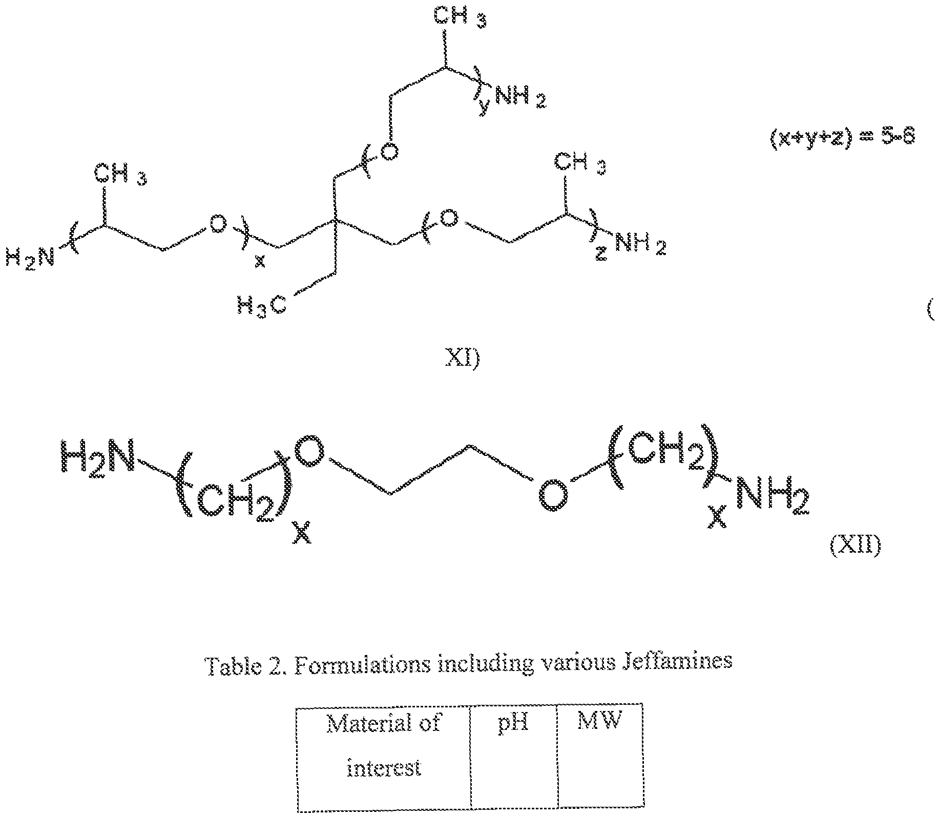
  • the chemical structures of the Jeffamines used are presented below. Specifically, the Jeffamines were mixed 50% w/w with deionized water prior to encapsulation.
  • the shell material used for these formulations was 1 ,0 ⁇ hexajnedlol dimethacrylate, HDDA (V).
  • the encapsulation was performed via a WOW (water-in ⁇ oil-in- water) emulsion due to the high solubility of Jeffamines in water.
  • the core solution includes Jeffaniine 50% w/w with deionized water and fluorescein.
  • FIGS. 6-11 show the particles resulted using D-230 Jeffamine (X) before (FIG. 6) and after crashing (FIG. 7), FIGS.
  • FIGS. 8 and 9 show the particles including T-403 Jeffamine (XI) before (FIG. 8) and after crushing (FIG. 9), and FIGS. 10 and 11 show the particles including XTJ-504 Jeffamine (XII) before (FIG. 10) and after crashing (FIG. 1 1).
  • the particles shown in FIGS. 6-11 have a diameter ranging from about. 25 microns to about 100 microns.
  • the shell tliickness varies across samples, but each appeared to be multi-core which may be favored by a high ratio of shell material to core material.
  • the thickness of the shell may depend on the type of material of interest to be encapsulated, as well as on the likelihood of escaping from encapsulant (i.e., protons are small in the case the encapsulated material is an acid).
  • cured HDDA (V) particles with encapsulated Jeffamines were prepared via WOW approach.
  • the formulations used are presented below in Table 3.
  • Tween ® 80 solution is a non-ionic viscous liquid available from Sigma-AIdrich. The pH of the solution was modified to neutral after washing and remained neutral for several days.
  • Particles including poly (pentaerytl ritol tetraacryiate) (PETRA) were prepared using a WOW approach.
  • the chemical structure of the monomer used (I) is presented above. Due to its chemical structure, PETRA is a highly-crosslirsked polymer and as result, increases the briitleness of the core-shell particles, The resulted particles have aqueous cores that also irsclude Rhodamine B as a fluorescent marker. The appearance of the particles was analyzed by fluorescence microscopy (no t shown). The average size of the resulted particles is about 50 microns.
  • a water soluble mixture was prepared using surfactant, 1% Tween ® 80, 0.2% Plutonic ® F127, and Rhodamine B (as a tracer), Such mixture was encapsulated using two different polymer formulations.
  • one formulation included a mixture of cyeiohexyl acrylate (III) Methylene glycol dimethaeryiate, TEGDMA ( ⁇ ),
  • a second mixture contained aliyl rnethacrylate (IY)/triethyIene glycol dimethaeryiate ( ⁇ ).
  • the appearance of the core-shell particles prepared using such formulations was analyzed by SEM. Referring now to FIGS, 12 and 13, FIGS, 12 and 13 show SEM pictures of core-shell particles prepared using the two formulations, and (IV)/(I1), respectively, which were cured through photoinitiation.
  • the shell toughness was modified by incorporating co-polymerized samples, such as by incorporating more amorphous areas into the linear hexanedtol diacrylate, HDDA (V), Specifically, solid particles such as hydrogels and core-shell particles were both prepared using the same polymer ratios (2:1 HDDA to PEDGMA), where PEDGMA (FX) is polyethylene glycol dimethacrylate (PEGgooDMA). The solid particles were much larger and polydispersed. but may give an indication of the shell properties, as well as on the formation mechanism. The size of the core-shell particles was approximately 1 micron. No fluorescence could be detected from core-shell particles due to low intensity likely from small particle size.
  • FIG. 14 illustrates a SEM picture of hydrogels formed according to the present example.
  • Optical microscopy images depict single core hydrogels.
  • such particles may be prepared as nano particles and use in treatment methods of the formation, when they are released into the formation, In such an embodiment, the release of the encapsulated material is based on a first release triggered by shear, followed by a second release triggered by temperature or time.
  • oil-soluble materials that are not crosslinked were incorporated into the shell.
  • the use of such materials allows for formation of areas of potentially lower strength in order to promote breakage.
  • hexadeeane C3 ⁇ 4(CH 2 )i4C3 ⁇ 4
  • HDDMA 1,6 hexanediol dimethyacrylate
  • the size of the resulted particles ranged from 20 to 125 microns. It was observed that the addition of the hexadecane reduced the poiydispersity. Prior to testing, the particles were stored in base oil at 80°C for 2 hours,
  • an AR2GG0EX Rheometer with Environmental Testing Chamber was used to study and predict behavior of polymers and materials under different flow, environmental, and processing conditions (temperature, shear rate, etc.).
  • the available geometries are concentric cylinder arid rotor (shear rates up to 4355 1/sec), parallel plates, cone and plate and Peltier plate, Rheoiogy was measured using a FANN Model 35A Viscometer (bob and sleeve model with a shear rate up to 1022 1/sec) (not shown) having a Farm Yield Stress Adapter (FYSA).
  • a Waring blender with a glass cup capable of speeds up to 23 K rpm
  • a Hamilioon Beach HMD200 mixer capable of speeds up to 24 rpm
  • EXAMPLE 9 in order to determine if the ability to observe shear dependent breakage is limited to certain size ranges using the available tools described above, a size dependent breakage study was performed.
  • the study involved core-shells particles with water/Rhodarnine B cores and PETRA shells, prepared by WOW approach.
  • the core-shell particles were dispersed in 101618 base oil.
  • the particles were from the same batch to ensure identical shell composition.
  • the particles were binned into three size ranges (smal!-50 microns, minimrn-75 microns and large-118 microns) by a centrifuge/settling process,
  • the size range had an impact on the ability to break the particles apart. Larger particles tended to break more easily than smaller particles, with almost no breakage in the very smallest size ranges. Without being bond by theory, the inventors of the present disclosure believe that the limiting factor in this embodiment may be that the handheld homogenizer's rotor/stator gap distance is roughly 220 microns, so anything within that scale will likely be destroyed by mechanical means. Referring now to Table 5, ' Fable 5 shows the experimental data obtained when an Omni handheld homogenizer having a 10 mm probe was used.
  • FIG. 15 depicts an Image particle analysis which was performed by setting the sphericity limits and calculating the area of particles within an image.
  • the experimental data is shown in Table 6 below.
  • the ouput was particle area calibrated by scale bar in microscopy image.
  • FIGS. 16-18 show SEM images of particles with TMPTA shells which were broken by using an Omni homogenizer having a 10 mm probe.
  • the volume of the solution was 20 ml, and the shearing was performed for I min at a shear rate of 10 K s,
  • HDDMA hexadecane shells a release study was performed. Specifically, core-shell particles having HDDMA/hexadecane shells and a water/fluorescein core solution were prepared using HDDMA (VII) with 25% hexadecane by a double emulsion WOW approach. The particles were stored in water at room temperature or 80°C for 2 hours prior to testing, After shear, particles were centrifuged to leave behind a solution or released fluorescein, which was analyzed via UV ⁇ Vis spectroscopy. Referring now to FIG, 19, FIG. 19 shows the UV-Vis experimental findings in the presence or absence of shearing. The fluorescein peak emission is located at 511 nm. Table 8 shows the experimental conditions used for the UV-Yis spectroscopy studies,
  • embodiments of the present disclosure provide wellbore fluids and methods for treating a formation with such fluids that include a base fluid and a plurality of hydrogel particles or a plurality of core-shell particles suspended in the base fluid.
  • the particles suspended in the base fluid may withstand low temperature, low shear profiles and may selectively release encapsulated materials of interest under high temperature and high shear conditions. Additionally, encapsulation of materials of interest in the core-shell particles or hydrogels may improve the drilling efficiency.
  • Another aspect of the present disclosure is that the core-shell particles, as well as the hydrogel particles as described herein exhibit stability over week timescaie.
  • the wellbore fluids of the present disclosure may provide reduced environmental risks, as the materials used for the preparation of shells are conform with environmental, health and safety requirements,

Landscapes

  • Chemical & Material Sciences (AREA)
  • Engineering & Computer Science (AREA)
  • Life Sciences & Earth Sciences (AREA)
  • General Life Sciences & Earth Sciences (AREA)
  • Materials Engineering (AREA)
  • Organic Chemistry (AREA)
  • Geology (AREA)
  • Mining & Mineral Resources (AREA)
  • Physics & Mathematics (AREA)
  • Environmental & Geological Engineering (AREA)
  • Fluid Mechanics (AREA)
  • Geochemistry & Mineralogy (AREA)
  • Mechanical Engineering (AREA)
  • General Chemical & Material Sciences (AREA)
  • Chemical Kinetics & Catalysis (AREA)
  • Colloid Chemistry (AREA)
  • Manufacturing Of Micro-Capsules (AREA)
  • Oil, Petroleum & Natural Gas (AREA)
  • Polymerisation Methods In General (AREA)

Abstract

Wellbore strengthening compositions and methods of use are disclosed herein, where the wellbore strengthening compositions may include a base fluid and a plurality of hydrogel particles or a plurality of core-shell particles suspended in the base fluid.

Description

ENCAPSULATING POLYMERS AND SELECTIVE
ACTIVATIO THEREOF
CROSS REFERENCE TO RELATED APPLICATIONS
[0001] This application claims the benefit of U.S. Provisional Application No.
62/270,690 filed on December 22, 2015, incorporated by reference herein in its entirety.
BACKGROUND
[00021 During the drilling of a wellbore, various fluids are typically used in the well for a variety of functions, The fluids may be circulated through a drill pipe and drill bit into the wellbore, and then may subsequently flow upward through the wellbore to the surface. During this circulation, the drilling fluid may act to remove drill cuttings from the bottom of the hole to the surface, to suspend cuttings and weighting material when circulation is interrupted, to control subsurface pressures, to maintain the integrity of the wellbore until the well section is cased and cemented, to isolate the fluids from the formation by providing sufficient hydrostatic pressure to prevent the ingress of formation fluids into the wellbore, to cool and lubricate the drill string and bit, and/or to maximize penetration rate.
[0003] Wellbore fluids may also be used to provide sufficient hydrostatic pressure in the well to prevent the influx and efflux of formation fluids and wellbore fluids, respectively. When the pore pressure (the pressure in the formation pore space provided by the formation fluids) exceeds the pressure in the open wellbore, the formation fluids tend to flow from the formation into the open wellbore. Therefore, the pressure in the open wellbore is often maintained at a higher pressure than the pore pressure, However, when wellbore pressures are maintained above the pore pressure, the pressure exerted by the wellbore fluids may exceed the fracture resistance of the formation and fractures and induced mud losses may occur. F urther, formation fractures may result in the loss of wellbore fluid that decreases the hydrostatic pressure in the wellbore to decrease, which may in turn also allow formation fluids to enter the wellbore, As a result, the formation fracture pressure may define an upper limit for allowable wellbore pressure in an open wellbore while the pore pressure defines a lower limit. Therefore, one constraint on well design and selection of drilling fluids is the balance between varying pore pressures and formation fracture pressures or fracture gradients through the depth of the well
] As staled above,, wellbore fluids are circulated downhole to remove rock, as well as deliver agents to combat the variety of issues described above. Fluid compositions may be water- or oil-based and may contain weighting agents, surfactants, proppanis, viseosifiers, and fluid loss additives. However, for a wellbore fluid to be effective during wellbore operations, the fluid has to stay in the borehole. During drilling operations, variations in formation composition may lead to undesirable fluid loss events in which substantial amounts of wellbore fluid are lost to the formation through large or small fissures or fractures in the formation or through a highly porous rock matrix surrounding the borehole. While fluid loss is often associated with drilling applications, other fluids may experience fluid loss into the formation including wellbore fluids used in completions, drill-in operations, productions, etc. Lost circulation may occur naturally in formations that are fractured, highly permeable, porous, cavernous, or vugular.
] Lost circulation may also result from induced pressure during drilling.
Specifically, induced mud losses may occur when the mud weight, required for well control and to maintain a stable wellbore, exceeds the fracture resistance of the formations. A particularly challenging situation arises in depleted reservoirs., in which the drop in pore pressure effectively weakens a wellbore through permeable, potentially hydrocarbon-bearing rock formation, but neighboring or inter-bedded low permeability rocks maintain their pore pressure. This can make the drilling of certain depleted zones impossible because the mud weight needed to support the shale exceeds the fracture resistance of the sands and silts, Another unintentional method by which lost circulation can result is through the inability to remove low and high gravity solids from fluids, Without being able to remove such solids, the fluid density can increase, thereby increasing the hole pressure, and if such hole pressure exceeds the formation fracture pressure, fractures and fluid loss can result, SUMMARY
[ΘΟΘό] This summary' is provided to introduce a selection of concepts that are further described below in the detailed description, This summary is not intended to identify key or essential features of the claimed subject matter, nor is it intended to be used as an aid in limiting the scope of the claimed subject matter.
[0ΘΘ7] In one aspect, embodiments of the present disclosure are directed to wellbore strengthening compositions that may include a base fluid; and a plurality of hydrogel particles or a plurality of core-shell particles suspended in the base fluid.
[©008] In another aspect, methods in accordance with the present disclosure may include pumping a wellbore fluid into the formation, where the wellbore fluid may include a base fluid; and a plurality of hydrogel particles or a plurality of core-shell particles suspended in the base fluid.
[0009] Other aspects and advantages of the invention will be apparent from the following description and the appended claims.
BRIEF DESCRIPTION OF DRAWINGS
[OSIOJ FIG. 1 depicts a mechanism of formation of core-shell particles, in accordance with aspects of the present disclosure.
[ΘΘ11] FIG, 2 shows an optical microscopy image of core-shells particles, in accordance with aspects of the present disclosure.
[0012] FIG. 3 depicts a mechanism of formation of hydrogel particles, in accordance with aspects of the present disclosure.
[ΘΘ13] FIGS. 4 and 5 show an optical microscopy image of hydrogel particles, in accordance with aspects of the present disclosure,
[0014] FIGS. 6-14 show SEM images of core-shell particles, in accordance with aspects of the present disclosure.
[0015] FIG. 15 illustrates the experimental results of the size dependent breakage study, in accordance with aspects of the present disclosure. [0016] FIGS, 16-18 show SEM images of core-shell particles, in accordance with aspects of the present disclosure,
[§§17] FIG. 19 illustrates UV-Vis experimental data, in accordance with aspects of the present disclosure.
DETAILED DESCRIPTION
[0018] Generally, embodiments disclosed herein relate to encapsulating polymers present in a weilbore fluid arid selective activation thereof. More specifically, embodiments disclosed herein relate to weilbore fluids for downhoie applications formed of a base fluid and a plurality of hydrogel particles or a plurality of core-shell particles dispersed or suspended in the base fluid. The inventors of the present disclosure have found that polymers and pre-poiymer materials incorporated in encapsulating systems such as hydrogel or core-shell particles may preferentially release encapsulated components under shear conditions generated by pumping the weilbore fluid into a formation through an opening.
[ΘΘ19] According to the present embodiments by encapsulating a material of interest, such as a liquid or a solid suspended or dispersed in a base fluid, within an encapsulating shell (such as a polymer coating) or a polymeric matrix, the encapsulation effectively limits the interaction of the material of interest with other components of the weilbore fluid and allows for in situ release and reaction in the downhoie environment. While encapsulated, the material of interest remains dormant in the weilbore fluid. In one or more embodiments, the encapsulated material or materials may be released from an encapsulating shell or a polymeric matrix in response to an external stimulus or triggering event, such as by physical disruption of the encapsuiant. Once released, the encapsulated material may react in situ, for example, to form weilbore strengthening materials (such as a lost circulation material), a chemical sealing layer (in/of the filtercake) or a material that filters into the formation prior to reacting to aid in consolidation of the near- weilbore region of the formation. Additional examples of disrupting the encapsuiant to release other encapsulated materials that react in situ include, without limitation, acid generation for stimulation or filter cake cleanup; and oxidizers or anti-oxidants for cementing.
[®§20] According to the present embodiments, materials that may be encapsulated may be, for example, water soluble materials, The water soluble materials that have shown utility in the present disclosure may be selected from the group of polyether amines (such as Jeffamines. available from Huntsman, the Woodlands, TX), free water, organic acids (such as, for example, formic acid and acetic acid), mineral acids (sulfuric, boric, hydrochloric, hydrofluoric, etc.), and inorganic salts.
As discussed herein, the entrapment/encapsulation of a material may be performed through different preparative approaches. These may include for example formation of suspensions, interfaeial interactions and mini-emulsions. The preparative approaches that have shown utility in the present disclosure are formation of core-shell particles through a double emulsion approach and formation of hydrogei particles through an invert emulsion approach.
Core-Shell Particles
According to various embodiments, encapsulation of water soluble materials may be performed by means of a two stage emulsifleation approach, with the formation of a double emulsion. In such embodiments, a first aqueous phase is dispersed in an oleaginous continuous phase with the formation of a primary emulsion. Next, the primary emulsion may be dispersed in a second aqueous phase with the formation of a double emulsion. For example, a double emulsion may be formed by first dispersing water in an oil phase, thereby creating a primary water-in- oil emulsion (or a. "single" emulsion) and subsequently dispersing the primai emulsion in excess water with the formation of a water-in-oil-in-water, W/O/W, double emulsion. Thus, a W/O/W double emulsion may include droplets of oil dispersed in an aqueous environment. The oil droplets may form around aqueous droplets (such as water), in which hydrophiHc components may be dissolved, i Referring now to FIG, 1, an aqueous soluble material (not shown) is mixed with an aqueous discontinuous phase, such as for example, water, with the formation of a modified aqueous discontinuous phase 120, As described later, the aqueous phase may include other additives, such as a surfactant, Next, the modified aqueous phase may be mixed with an oleaginous continuous phase 1 10 (such as an oily monomer), with the formation of a primary emulsion 100, Referring still to FIG. 1, the primary emulsion 100 includes droplets 120 of the modified aqueous phase dispersed or emulsed in the oleaginous continuous phase 1 0. According to various embodiments, the oleaginous continuous phase may include at least a monomer, which upon polymerizaiion may form a polymeric shell or coating in which the water soluble material is encapsulated.
[0025] The primary emulsion 100 is mixed with a second aqueous phase 130, with the formation of a double emulsion 140. According to various embodiments, the first and the second aqueous phases may be identical or different, In one or more embodiments, the double emulsion 140 may be prepared by mixing together the primary emulsion 100 and excess water 130 using a high shear mixer, Next, the double emulsion formed as described above is treated by heat, when the monomer present in the oleaginous phase may polymerize with the formation of a polymeric shell or coating around the droplets 120 of the modified aqueous phase. Thus, core- shell particles 150 that are suspended or dispersed into the second aqueous phase 130 may form. In such embodiments, the core 120 of the particles may include droplets of the modified aqueous phase, i.e water and water soluble material, while the shell 160 is a rigid polymer formed by curing the monomer present in the oleaginous phase by heat. In such embodiments, the average particle size of the core-shell particles ranges from about 15 microns, to about 130 microns, where the lower limit may be any of 15 microns, 20 microns, 25 microns, and the upper limit can be any of 1 15 microns, 125 microns, 130 microns, where any lower limit can be used with any upper limit. Such a preparative approach is easy and fast as the synthesis part does not take a long period of time. However, it may generate larger, multi-core particles, as seen in FIG. 2. Referring now to FIG . 2, FIG. 2 shows an optical microscopy image of core-shell particles having acrylate shells and aqueous cores of salt solutions. As seen in FIG, 2, the core-shell particles 200 have multiple core phases within the particle.
[ΘΘ26] The monomers thai may be used to form the core-shell particles, for example, may be selected from the group of acrylates and acrylate derivatives, For example, in various embodiments, the polymers may be selected from the group of pentaerythritol tetraacrylate (I), triethylene glycol dimethacrylate (II), cyclohexyl acrylate (III), ally! methaerylate (IV), 1,6 hexanediol diacrylate, HDD A, (V), 1 J . , 1 -trimethylolpropane triacrylate (TMPTA) (VI), 1,6-hexanediol dimethacrylate, HDDMA, (VII), whose chemical structures are shown below.
Figure imgf000009_0001
Figure imgf000010_0001
Figure imgf000010_0002
As it will described later, in embodiments thai use 1,6 hexanediol dimethacryiate (VII) or pentaer thritol tetraaerylate (I), tough polymers may form upon polymerization of the monomer. In various embodiments, the formulations may be so strong that they may not show evidence of shear rupture, even under bazooka testing, due to high durability. It is also envisioned that mixtures of both tough and more flexible monomers may be used that promote breakage and stability, with tbe formation of co-polymerized shells or coatings. In one or more embodiments, soluble materials may be added to the monomer, when shear dependent rupture may be achieved. For example, in one or more embodiments, hexadecane may be added to a monomer, such as 1 ,ό-hexanediol dimethaerylate. As hexadecane is not crosslinked into the shell material, it may have more mobility than the cured polymer. 00281 Hydragel Particles
[0029] It is envisioned thai the encapsulation of water soluble materials may also be performed using a different preparative approach, such as a single emulsifi cation process as shown in FIG. 3, with the formation of hydrogel particles. Referring now to PIG, 3, a water soluble material (not shown) and a water soluble monomer (not shown) are mixed with an aqueous phase, with the formation of a modified non- oleaginous discontinuous phase. Next, the modified aqueous phase may be mixed with an oleaginous continuous phase 310, with the formation of an emulsion 300. Thus, the emulsion may include droplets of modified aqueous phase 320 dispersed in an oleaginous environment 310, i.e., the droplets 320 may include water, a water soluble monomer and a water soluble material of interest. Next, upon exposure to UV light, the water soluble monomer incorporated in the droplets 320 may polymerize with the formation of hydrogel particles 340, In such embodiments, the water soluble material of interest is encapsulated into the polymeric matrix of the hydrogels. According to various embodiments, the monomers used for the preparation of the hydrogels exhibit the following properties: 1) are compatible with the water soluble materials of interest; 2) form polymers that are robust enough to survive moderate shear and temperature; 3) are scalable; 4) they are conform to environmental, health and safety requirements. The monomers that have shown utility in the present disclosure may be selected from the group of water soluble aerylates and acrylate derivatives, such as for example 2-hydroxyethyl acrylate (HEA) (VIII), shown below, and ethylene glycol dimethylacrylate.
Figure imgf000011_0001
J The polymerization of the monomers may be performed using various polymerization methods. One polymerization method that has shown utility in the present disclosure is a UV Initiated radical chain polymerization (photoimtiation) that exhibits the benefits of being rapid, relatively low cost (both in materials and amount of initiator needed) and may form robust polymers (high conversion monomer to polymer). For example, upon curing by UV light, ethylene glycol dimethylacrylate forms polyethylene glycol (600) dimethylaerylate whose chemical structure (IX) is shown below.
Figure imgf000012_0001
below, As seen below, a photoinitiator is irradiated using UV light with the formation of radicals (1) which upon initiation (2) and further through propagation (3) and termination (4) stages generate the desired polymeric matrix.
Photoinitiation
(1)
Figure imgf000012_0002
Figure imgf000012_0003
! i
Figure imgf000013_0001
] According to various embodiments, the average particle size of the h drogel particles ranges from about 15 microns, to about 85 microns, where the lower limit may be any of 15 microns, 20 microns, 25 microns, and the upper limit can be any of 75 microns, SO microns, 85 microns, where any lower limit can be used with any upper limit. Such a prepai'ative approach is easy and fast. However, it may generate softer gels which may not be fully ruggedized. Referring now to FIGS. 4 and 5, FIGS, 4 and 5 show hydroxyethyl acrylate hydrogel particles 400 (FIG. 4) and 500 (FIG, 5) prepared according to the present embodiments. As seen in FIGS. 4 and 5, the hydrogels may have a wide size selection. ] According to the present embodiments, the encapsulated material of interest
(such as a water soluble material) may be designed such that the water soluble material may be released when exposed to shear forces such as those that occur during injection of a wellbore fluid downhole. For example, as a wellbore fluid containing a water soluble material encapsulated in a plurality of particles (such as core-shell particles or hydrogel particles) is exposed to shear forces that occur as the fluid exits an opening in a tubular, drill string, or drill bit, the shear forces may disrupt the particles and release the encapsulated material into the surrounding fluid. Thus, the release and delivery of an encapsulated material of interest may be obtained by timing the shear pressure experienced by the fluid in the wellbore. } Shear forces which are closely related to the pressure drop experienced by a wellbore fluid passing through constrictions in various pumps, pipes, and drill-bits may be sufficient to release the encapsulated component. Without being bound by any theory , the inventors believe that the combination of shear and elongational flow experienced in these conditions may produce enough stress to break the particles, such as core-shell particles or hydrogels that encapsulate the material of interest. Basically, the stress might first come from the turbulence experienced in the pumps of surface equipment and within the wellbore fluid itself. After that, the passage of the flow through a restriction creates first some sort of "Venturi effect" with an acceleration of the wellbore fluid which may have the effect of deforming the encapsulant and then at the outlet of the restriction another deformation of the encapsulate coming from the wellbore fluid deceleration, Velocity increases and decreases are of the order of 50 to 100 times variation. Strain rates experienced in restriction are from 1000 to one million reciprocal second, more specifically 10000 to 200000 reciprocal second. The inventors have noticed that even if the stress experienced during pumping and along the transportation has an effect on the breakage of the encapsulant, the stress and/or velocity difference which is obtained due to the flow tlirough a restriction may be of paramount importance, The stress is closely related to the pressure drop encompassed in each unit of the well treatment (pumps, pipes, drill -bit). A higher pressure drop corresponds to a higher stress applied. The highest stress is observed when the fluid passes through the nozzles in a drill bit or a port of the completion string downhole. By stress sufficient to break the encapsulant, it is to be understood in the context of the present disclosure that said sufficient stress is produced by the passage through the nozzles of the drill bit or similar restriction to allow the material of interest to be released from the encapsulant. The pressure drop observed when passing through the nozzles is from about 150 to 5000 psi (10 to 345 bar), more specifically from 300 to 5000 psi (20 to 345 bar), most specifically from 300 to 1000 psi (20 to 69 bar). As shown earlier, the stress may sometimes also be referred to as a velocity difference. While not bound by a particular theory, it is believed that the shear forces activate the points of contact of the encapsulated material of interest., by applying pressure and therefore, breaking them.
'■ In one or more embodiments, the shell of the core-shell particles or the polymeric matrix of the hydroge! particles may be designed such that the shell or the matrix ruptures when exposed to shear forces of at least 10,000 s" m some embodiments, at least 20.000 s~! in other embodiments, or at least 30,000 s-i in yet other embodiments Such shear forces may be selectively induced through eavitating and structured drill bits to enable control over the rupture of the shell or matrix.
] According to the present embodiments, the base fluids described herein may be oil-based fluids, aqueous-based fluids or emulsions thereof. The oleaginous fluid may be a liquid and more specifically is a natural, mineral or synthetic oil. In some embodiments, the oleaginous fluid may be selected from the group including petroleum oil, a silicone oil, a synthetically derived oil, such as hydrogenated and tinhydrogenated olefins including polyalpha olefins, linear and branch olefins and the like, polydiorganosiloxanes, siioxanes, or organosiloxanes, esters of fatty acids, specifically straight chain, branched and cyclical alkyl ethers of fatty acids, mixtures thereof and similar compounds known to one of skill in the ait.
In various embodiments, the aqueous base fluid may generally be any water base fluid phase. In one or more embodiments, the aqueous base fluid may be selected from fresh water, sea water, brines, mixtures of water or brine and water- soluble organic compounds, and mixtures thereof. In those embodiments of the disclosure where the aqueous medium is a brine, the brine may include water and an inorganic salt or an organic salt. The salt may serve to provide a portion of the fluid's density (to balance against the formation pressures), and may also reduce the effect of the water based fluid on hydratable clays and shales encountered during completion. In various embodiments, the brine may include seawater, aqueous solutions wherein the salt concentration is less than that of sea water, or aqueous solutions wherein the salt concentration is greater than that of sea water. Salts that may be found in seawater include, hut are not limited to, sodium, calcium, aluminum, magnesium, potassium, strontium, and lithium salts of chlorides, bromides, carbonates, iodides, chlorates, brornaies, formates, nitrates, oxides, sulfates, silicates, phosphates and fluorides. Salts that may be incorporated in a brine include any one or more of those present in natural seawater or any other organic or inorganic dissolved salts. Additionally, brines that may be used in the drilling fluids disclosed herein may be natural or synthetic. ] In one or more embodiments, the base fluid may be prepared using an invert emulsion where a non-oleaginous discontinuous (or aqueous liquid) phase is emulsed within an oleaginous continuous phase. The preparation of an invert emulsion, such as for example, a water-in-oil (W/O) emulsion, may be done according to the methods and processes known to a person of skill in the art. As noted above, the aqueous discontinuous phase of die emulsion may include one or more materials of interest that may be encapsulated in various particles, such as core-shell particles or hydrogels. In such embodiments, the oleaginous continuous phase and the aqueous discontinuous phase may be selected from any of the liquid phases discussed above. The concentration of the oleaginous fluid should be sufficient so that an invert emulsion forms and may be less than about 99% by volume of the invert emulsion, in one embodiment the amount of oleaginous fluid is from about 30% to about 95% by volume and more specifically about 40% to about 90% by volume of the invert emulsion fluid. The oleaginous fluid in one embodiment may include at least 5% by volume of a material selected from the group including esters, ethers, acetals, dialkylearbonates, hydrocarbons, and combinations thereof. In such embodiments, the amount of the aqueous fluid is less than the theoretical limit needed for forming an invert emulsion. Thus, in one embodiment, the amount of aqueous fluid is less than about 70% by volume, and more specifically from about 1% to about 70% by volume. In another embodiment, the aqueous fluid is from about 5% to about 60% by volume of the invert emulsion fluid. Upon formation of the encapsulated particles, conventional methods can be used to prepare the wellbore fluids disclosed herein, fn one embodiment, a desired quantity of oleaginous fluid such as a base oil and a suitable amount of a surfactant are mixed together and the remaining components are added sequentially with continuous mixing. An invert emulsion may also be formed by vigorously agitating, mixing or shearing the oleaginous fluid and the non-oleaginous fluid.
Upon mixing, the fluids of the present embodiments may be used in wellbore operations, such as in drilling fluids or treatment operations. Such operations are known to persons skilled in the art and involve pumping a wellbore fluid into a wellbore through an earthen formation and performing at least one wellbore operation while the wellbore fluid is in the wellbore. [0041 One embodiment of the present disclosure involves a method of treating a formation. In one such an illustrative embodiment, the method involves pumping a wellbore fluid into the formation, Such a wellbore fluid includes a base fluid and a plurality of hydrogel particles or a plurality of core-shell particles suspended in the base fluid.
[0042J Other additives that may be included in the wellbore fluids disclosed herein include for example, wetting agents, organophilic clays, viseosifiers, surfactants, dispersants, interfaeial tension reducers, pH buffers, mutual solvents, thinners, thinning agents and cleaning agents. The addition of such agents should be well known to one of ordinary skill in the art of formulating drilling fluids and muds.
[0043] it is also envisioned that the wellbore fluids of the present disclosure may include an emulsifier. The emulsifier is a surface acting agent selected from the group of fatty acids, soaps of fatty acids, amidoaniines, polyamides, polyamines, oleate esters, such as sorbitan monoleate, sorbitan dioleate, imidazoline derivatives or alcohol derivatives and combinations or derivatives of the above,
[©044] Wetting agents that may be suitable for use in the fluids disclosed herein include crude tall oil, oxidized crude tall oil, surfactants, organic phosphate esters, modified imidazolines and amidoammes, alkyl aromatic sulfates and sulfonates, and the like, and combinations or derivatives of these. However, when used with the invert emulsion fluid, the use of fatty acid wetting agents should be minimized so as to not adversely affect the reversibility of the invert emulsion disclosed herein. FAZE- WET™, VERSACOAT™, SURE WET™, VERSA WET™, and VERSA WET™ NS are examples of commercially available wetting agents manufactured and distributed by M-i L.L.C. that may be used in the fluids disclosed herein. Silwet L-77, L-7001, L-7605, and L-7622 are examples of commercially available surfactants and wetting agents manufactured and distributed by General Electric Company (Wilton, CT).
[θ§45] Organophilic. clays, normally amine treated clays, may be useful as viseosifiers and/or emulsion stabilizers in the fluid composition disclosed herein. Other viseosifiers, such as oil soluble polymers, polyamide resins, poiycarboxylic acids and soaps can also he used. The amount of viscosifier used in the composition can vary upon the end use of the composition, in one or more embodiments the viseosifier may have a concentration of about 0.1% to about 6% by weight. VG-69'M and YG-FLUS™ are organoclay materials distributed by M-I, L.L.C., Houston, Texas, and VER.SA~HRP; M is a polyamide resin material manufactured and distributed by M-I L .C, that xnay be used in the fluids disclosed herein,
[Θ04 ] EXAMPLES
[Θ047] The following examples are presented to further illustrate the preparation and
properties of the wellbore fluids of the present disclosure and should not be construed to limit the scope of the disclosure, imless otherwise expressly indicated in the appended claims,
[ΘΘ481 EXAMPLE 1
[©1)491 Various particles were prepared using different acrylates, by both double
emulsion and one stage emulsion approach, as shown below in Table L To assess the appearance of the particles, fluorescent tracers were incorporated into the particles to aid in visualization of encapsulation, particle morpbology aud release.
The shell chemistry refers to the chemical formulae to IX, referenced and shown above.
Table 1 , Particle formulations
Shell Density Tg Description Materials used Particle Observations Chemistry CQ for size
g/mL
encapsulation (μτχι)
Double emulsion
Ϊ 1.19 Highly cross- Water, 75-200
linked, brittle surfactant,
polymer hodamine B
I II 1.092 Flexible Water, Used in
surfactant, combination colored dyes wi t additional monomers ill 0.975 -5 Bulky Water, 75-120
backbone surfactant,
RJiodamine B
j IV 0.938 Tough Water, 50400
polymer surfactant,
materials Rhodamine B V 1.01 Quick curing, Water, colored 25-100
often used as dyes,
a diluent for fluorescein,
other Jeffamines, \ monomers surfactant
VI 1.06 Trifunetional, I Water, with 200-400 Very large
brittle, fast fluorescein, particles, but curing, forms surfactant brittle larger
particles j
νπ 0.995 Brittle, fairly Water with -400 Several
rigid fluorescein, batches of VI!
Jeffamines, (HDDMA) surfactant particles
incorporated hexadecane into the shell material
Hydrogels
VIII 1.1 Soft, flexible 5M NaCl with 1 5-75 1 Material
gel fluorescein, agglomerated surfactant In transport IX 1.1 1 -60 Moderately 5M NaCi with I 25-100 Material
soft, rubbery fluorescein, agglomerated polymer surfactant in transport
The hydrogei particles of 2-hydroxyeihyl acrylate (VIII) (as shown in FIG. 5) and polyethylene glycol dimethacrylate (IX) (not shown) have a matrix swollen with a solution containing water, surfactant and a fluorescent tracer. Due to the open structure of the pol mer matrix, a high ratio of material of interest to polymer was used. The hydrogei particles tend to be sticky and are flexible as the formulations are not ruggedized. Both types of particles were too soft and agglomerated in oil during shipping. n addition, they were difficult to be resuspended.
EXAMPLE 2
To asses the properties of Jeffamines-based particles various Jeffamines, namely D-230 (XX T-403 (XI) and XTJ-504 (XII), were used as shown below in Table 2.
The chemical structures of the Jeffamines used are presented below. Specifically, the Jeffamines were mixed 50% w/w with deionized water prior to encapsulation. The shell material used for these formulations was 1 ,0~hexajnedlol dimethacrylate, HDDA (V). The encapsulation was performed via a WOW (water-in~oil-in- water) emulsion due to the high solubility of Jeffamines in water. The core solution includes Jeffaniine 50% w/w with deionized water and fluorescein.
Figure imgf000020_0001
Figure imgf000020_0002
D-230 (X) 12 230
T-403 (XI) 12 440
XTJ-504 (XII) 13 148
The evaluation (not shown) of the jeffamine based particles was performed by optical microscopy in the presence of fluorescein. It was found that the resulting Jeffamine-based particles exhibit single and multi-cores, in addition, some of the particles appeared to be folly fluorescent (not shown) (no distinction between core and shell), which is a common artifact when imaging fluorescent materials. To fully assess the appearance of the Jeffamine-based particles, Scanning Electron Microscopy (SEM) was performed before and after manually crashing the samples to enable visualization of the interior. Referring now to FIGS. 6-11, FIGS. 6 and 7 show the particles resulted using D-230 Jeffamine (X) before (FIG. 6) and after crashing (FIG. 7), FIGS. 8 and 9 show the particles including T-403 Jeffamine (XI) before (FIG. 8) and after crushing (FIG. 9), and FIGS. 10 and 11 show the particles including XTJ-504 Jeffamine (XII) before (FIG. 10) and after crashing (FIG. 1 1). According to the SEM analysis, the particles shown in FIGS. 6-11 have a diameter ranging from about. 25 microns to about 100 microns. As seen in FIGS, 7, 9 and 1 1, the shell tliickness varies across samples, but each appeared to be multi-core which may be favored by a high ratio of shell material to core material. The thickness of the shell may depend on the type of material of interest to be encapsulated, as well as on the likelihood of escaping from encapsulant (i.e., protons are small in the case the encapsulated material is an acid).
To further study the encapsulation efficiency of the Jeffamine samples, cured HDDA (V) particles with encapsulated Jeffamines were prepared via WOW approach. The formulations used are presented below in Table 3. During the process of generating the particles, some of the Jeffamine material was not encapsulated, which lowered the overall pH of the second water phase, W2, Particles were washed via centrifugaiion in a deionized water/Tween® 80 solution to aid in resuspension. Tween® 80 solution is a non-ionic viscous liquid available from Sigma-AIdrich. The pH of the solution was modified to neutral after washing and remained neutral for several days.
Table 3. Formulations including various Jeff amines
Figure imgf000022_0001
[0055] EXAMPLE 3
[©056] Particles including poly (pentaerytl ritol tetraacryiate) (PETRA) were prepared using a WOW approach. The chemical structure of the monomer used (I) is presented above. Due to its chemical structure, PETRA is a highly-crosslirsked polymer and as result, increases the briitleness of the core-shell particles, The resulted particles have aqueous cores that also irsclude Rhodamine B as a fluorescent marker. The appearance of the particles was analyzed by fluorescence microscopy (no t shown). The average size of the resulted particles is about 50 microns.
[0057] EXAMPLE 4
[0058] Different polymers were further screened for shear dependent rupture. For example, a water soluble mixture was prepared using surfactant, 1% Tween®80, 0.2% Plutonic® F127, and Rhodamine B (as a tracer), Such mixture was encapsulated using two different polymer formulations. For example, one formulation included a mixture of cyeiohexyl acrylate (III) Methylene glycol dimethaeryiate, TEGDMA (Π), A second mixture contained aliyl rnethacrylate (IY)/triethyIene glycol dimethaeryiate (ΪΙ). The appearance of the core-shell particles prepared using such formulations was analyzed by SEM. Referring now to FIGS, 12 and 13, FIGS, 12 and 13 show SEM pictures of core-shell particles prepared using the two formulations, and (IV)/(I1), respectively, which were cured through photoinitiation.
EXAMPLE 5 in order to promote breakage and stability, the shell toughness was modified by incorporating co-polymerized samples, such as by incorporating more amorphous areas into the linear hexanedtol diacrylate, HDDA (V), Specifically, solid particles such as hydrogels and core-shell particles were both prepared using the same polymer ratios (2:1 HDDA to PEDGMA), where PEDGMA (FX) is polyethylene glycol dimethacrylate (PEGgooDMA). The solid particles were much larger and polydispersed. but may give an indication of the shell properties, as well as on the formation mechanism. The size of the core-shell particles was approximately 1 micron. No fluorescence could be detected from core-shell particles due to low intensity likely from small particle size. Without being bound by theory, the inventors of the present disclosure believe that this particle generation mechanism may lead towards a higher percentage of single core particles. Referring now to FIG. 14, FIG. 14 illustrates a SEM picture of hydrogels formed according to the present example. Optical microscopy images (not shown) depict single core hydrogels. It is also envisioned that such particles may be prepared as nano particles and use in treatment methods of the formation, when they are released into the formation, In such an embodiment, the release of the encapsulated material is based on a first release triggered by shear, followed by a second release triggered by temperature or time.
EXAMPLE 6
To further study shear dependent rupture, oil-soluble materials that are not crosslinked were incorporated into the shell. The use of such materials allows for formation of areas of potentially lower strength in order to promote breakage. For example, hexadeeane, C¾(CH2)i4C¾, was incorporated into 1,6 hexanediol dimethyacrylate (HDDMA) (V II) at 5%, 10% and 25% weight of monomer. The size of the resulted particles ranged from 20 to 125 microns. It was observed that the addition of the hexadecane reduced the poiydispersity. Prior to testing, the particles were stored in base oil at 80°C for 2 hours,
EXAMPLE 7
To assess the Theological properties of the particles formed, an AR2GG0EX Rheometer with Environmental Testing Chamber (ETC) was used to study and predict behavior of polymers and materials under different flow, environmental, and processing conditions (temperature, shear rate, etc.). The available geometries (not shown) are concentric cylinder arid rotor (shear rates up to 4355 1/sec), parallel plates, cone and plate and Peltier plate, Rheoiogy was measured using a FANN Model 35A Viscometer (bob and sleeve model with a shear rate up to 1022 1/sec) (not shown) having a Farm Yield Stress Adapter (FYSA).
EXAMPLE 8
For shear testing, an OMNI TH handheld homogenizer capable of speeds up to 35 rpm was used with low volumes. For such an instrument, the shear rate is dependent on the rotor diameter and the gap between the rotor and stator. Referring now to Table 4, Table 4 shows shear- rates for the Omni TH handheld.
Table 4. Shear rates for the Omni TH handheld
Figure imgf000024_0001
For mud formulation, two types of blenders were used, namely a Waring blender with a glass cup (capable of speeds up to 23 K rpm) and a Hamilioon Beach HMD200 mixer (capable of speeds up to 24 rpm),
EXAMPLE 9 in order to determine if the ability to observe shear dependent breakage is limited to certain size ranges using the available tools described above, a size dependent breakage study was performed. The study involved core-shells particles with water/Rhodarnine B cores and PETRA shells, prepared by WOW approach. The core-shell particles were dispersed in 101618 base oil. The particles were from the same batch to ensure identical shell composition. The particles were binned into three size ranges (smal!-50 microns, mediurn-75 microns and large-118 microns) by a centrifuge/settling process,
I It was observed that, the size range had an impact on the ability to break the particles apart. Larger particles tended to break more easily than smaller particles, with almost no breakage in the very smallest size ranges. Without being bond by theory, the inventors of the present disclosure believe that the limiting factor in this embodiment may be that the handheld homogenizer's rotor/stator gap distance is roughly 220 microns, so anything within that scale will likely be destroyed by mechanical means. Referring now to Table 5, 'Fable 5 shows the experimental data obtained when an Omni handheld homogenizer having a 10 mm probe was used.
Table 5. Size dependent breakage study
Figure imgf000025_0001
EXAMPLE 10
To further assess the properties of the particles prepared as disclosed herein, an image particle analysis was performed. Referring now to FIG. 15. FIG. 15 depicts an Image particle analysis which was performed by setting the sphericity limits and calculating the area of particles within an image. The experimental data is shown in Table 6 below. The ouput was particle area calibrated by scale bar in microscopy image.
Table 6. Particle area calibrated by scale bar in microscopy image Sample Area Diameter
no.
1 16420.08 5206.1 72.15 144.31
2 3551.84 1 126.14 33.56 67.12
3 1637.30 519.12 22.78 45,57
4 54310.75 17219.64 131.22 262.45
5 2819.50 893.95 29.90 59.80
6 3763.70 1 193.31 34.54 69.09
7 3700.93 1 173.41 34.26 68.51
8 2296,41 728.09 26.98 53.97
9 4783.74 1516.72 38.95 77.89
10 37673.59 11944.70 109.29 218.58
11 33378.95 10583.05 102.87 205.75
12 13843.82 4389.29 66.25 132.50
Larg particles
Large particle average 118.16
Minimum size 9.26
Maximum size 339.92
[Θ673] EXAMPLE 11
[0074] In order to evaluate the shearing, optical microscopy images (not shown) were recorded before and after shearing on fluids containing core-shell particles containing water and blue dye cores and HDDA (V) shells. When an Omni homogenizer having a 10 mm probe was used, the results showed minimal evidence of particle breakage. The majority of the particles remained intact at 8,4 , 1 mm. it was observed that the Waring blender caused some particle aggregation, but the particles remained, intact at 15 3 1 min, '['able 7 shows the experimental conditions used for optical microscopy studies performed before and after shearing. In the case of using the Omni homogenizer, the approximate shear rate was 15,0000 s"1.
Table 7. Experimental data used for shearing of core-shell particles with HDDA shells
Mixer/Shear device Time Speed (rpm) Volume
Waring blender 30 s, 1 min. 15 K 100 ml Hamilton Beach 30 s. 1 rain. 21 .00 ml
Omni homogenizer 30 s, 1 mm. 20 ml with a 10 mm probe
[0075] EXAMPLE 12
[Θ 76] In order to evaluate the shear of core-shell particles having TMPTA (VI) shells, an Omni homogenizer with a 10 mm probe was used for large, multi-core particles having deionized water cores and TMPTA shells. The shearing was performed in base oil (101618). It was observed that breakage occurred in chunks of particle and did not result in the complete destruction of the particle shell Without being bond by the theory, the inventors of the present disclosure believe that the breakage profile may be a result of the high shell to core ratio. Referring now to FIGS. 16-18, FIGS. 16-18 show SEM images of particles with TMPTA shells which were broken by using an Omni homogenizer having a 10 mm probe. The volume of the solution was 20 ml, and the shearing was performed for I min at a shear rate of 10 K s,
[0077] EXAMPLE 13
[§078] Particles containing HDDMA hexadecane shells prepared by using the WOW approach were stored at 80°C for 2 hours. The particles were prepared using 5%, 10% and 25% hexadecane, The particles had an average size of approximately 100 microns or less. Shearing was performed at 20 K/s for 2 rnin. Optical microscopy images (not shown) taken before and after shear indicate that particles showed more signs of breakage over HDDMA (VII) alone (fractured pieces, particle remnants). Thus, the study indicated breakage upon shearing, despite the fact that these particles are in the medium size range which may not demonstrate breaking under size dependent shear testing.
[§§79] To further assess the properties of the core-shell particles having
HDDMA hexadecane shells, a release study was performed. Specifically, core-shell particles having HDDMA/hexadecane shells and a water/fluorescein core solution were prepared using HDDMA (VII) with 25% hexadecane by a double emulsion WOW approach. The particles were stored in water at room temperature or 80°C for 2 hours prior to testing, After shear, particles were centrifuged to leave behind a solution or released fluorescein, which was analyzed via UV~Vis spectroscopy. Referring now to FIG, 19, FIG. 19 shows the UV-Vis experimental findings in the presence or absence of shearing. The fluorescein peak emission is located at 511 nm. Table 8 shows the experimental conditions used for the UV-Yis spectroscopy studies,
Ί able 8, Experimental conditions for the UV-Vis spectroscopy studies
Figure imgf000028_0001
[0080] It was observed that there is a major difference between shear at room temperature and shear under heated conditions. For example, the release after 2 hours at 80°C is much greater than at room temperature (i.e. , more than 50% breakage of the shell), where the release is comparative, not quantitative. It was also observed that the fluorescent strength in solution increased with both heat and shear.
[0081] EXAMPLE 13
[Θ082] Stability studies in base oil and brine were performed on two types of core- shell particles. Specifically, the stability of particles having HDDMA/hexadecane (25 wt,%) shells and particles having PETRA was studied. It was observed that the shells of both samples maintained morphology after hot storage for several weeks. I case of particles having PETRA shells it was noticed that the particles agglomerated in brine. Fluorescence (not shown) was still visible from both samples after performing the stability testing. Other samples were tested in brine containing 25% C C^ and base oil (separately) for extended periods of time at 80°C to monitor stability. [0083] Advantageously, embodiments of the present disclosure provide wellbore fluids and methods for treating a formation with such fluids that include a base fluid and a plurality of hydrogel particles or a plurality of core-shell particles suspended in the base fluid. The particles suspended in the base fluid may withstand low temperature, low shear profiles and may selectively release encapsulated materials of interest under high temperature and high shear conditions. Additionally, encapsulation of materials of interest in the core-shell particles or hydrogels may improve the drilling efficiency. Another aspect of the present disclosure is that the core-shell particles, as well as the hydrogel particles as described herein exhibit stability over week timescaie. Furthermore, the wellbore fluids of the present disclosure may provide reduced environmental risks, as the materials used for the preparation of shells are conform with environmental, health and safety requirements,
[0084] Although only a few example embodiments have been described in detail above, those skilled in the art will readily appreciate thai many modifications are possible in the example embodiments without materially departing from this invention. Accordingly, all such modifications are intended to be included within the scope of this disclosure. In the claims, means-plus-function clauses are intended to cover the structures described herein as performing the recited function and not only structural equivalents, but also equivalent structures. Thus, although a nail and a screw may not be structural equivalents in that a nail employs a cylindrical surface to secure wooden parts together, whereas a screw employs a helical surface, in the environment of fastening wooden parts, a nail and a screw may be equivalent structures. It is the express intention of the applicant not to invoke 35 U.S.C. § 112, paragraph 6 for any limitations of any of the claims herein, except for those in which the claim expressly uses the words 'means for' together with an associated function.

Claims

CLAIMS What is claimed:
1. A welibore fluid comprising:
a base fluid; and
a plurality of hydrogel particles or a plurality of core-shell particles suspended in the base fluid.
2. The welibore fluid of claim 1, wherein the base fluid is an oil-based fluid, an aqueous- based fluid or an emulsion thereof.
3. The welibore fluid of claim L wherein the plurality of hydrogel particles or the plurality of core-shell particles are formed from at least a monomer selected from the group of acrylates and acrylate derivatives.
4. The welibore fluid of claim 3, wherein the plurality of core-shell particles further comprise an organic solvent.
5. The welibore fluid of claim 4, wherein the organic solvent is hexadeeane.
6. The welibore fluid of claim 3, wherein the plurality of hydrogel particles or the plurality of core-shell particles encapsulate a water soluble material
7. The welibore fluid of claim 6, wherein the water soluble material is selected from the group of poly ether amines, free water, organic acids and inorganic salts,
8. The welibore fluid of claim 3, wherein the plurality of hydrogel particles have an average size ranging from about 15 to about 85 microns.
9. The welibore fluid of claim 3, wherein the plurality of core-shell particles have an average size ranging from about 15 microns to about 130 microns.
10. The welibore fluid of claim 6, wherein the encapsulated water soluble material is released by subjecting the plurality of hydrogel particles or the plurality of core-shell particles to shear forces generated by pumping the wellbore fluid into a formation through an opening.
1 1. A method of treating a formation, the method comprising:
pumping a wellbore fluid into the formation, the wellbore fluid comprising:
a base fluid; and
a plurality of hydrogel particles or a plurality of core-shell particles suspended in the base fluid.
12. The method of claim 1 1, wherein the base fluid is an oil-based fluid, an aqueous-based fluid or an emulsion thereof.
13. The method of claim 1 L wherein the plurality of hydrogel particles or the plurality of core-shell particles are formed from at least a monomer selected from the group of acrylates and acrylate derivatives.
14. The method of claim 13, wherein the plurality of core-shell particles further comprise an organic solvent.
15. The method of claim 14, wherein the organic solvent is hexadeeane,
16. The method of claim 13, wherein the plurality of hydrogel particles or the plurality of core-shell particles encapsulate a water soluble material.
17. The method of claim 16, wherein the water soluble material is selected from the group of polyeiher amines, free water, organic acids and inorganic salts.
18. The method of claim 13, wherein the plurality of hydrogel particles have an average size ranging from about 15 to about 85 microns.
19. The method of claim 13, wherein the plurality of core-shell particles have an average size ranging from about 15 microns to about 130 microns.
20. The method of claim 16, wherein the encapsulated water soluble material is released by subjecting the plurality of hydrogel particles or the plurality of core-shell particles to shear forces generated by pumping the wellbore fluid into a formation through an opening. , The method of claim 20, wherein the shear forces trigger a first release, and a second release is triggered by temperature or time.
PCT/US2016/068271 2015-12-22 2016-12-22 Encapsulating polymers and selective activation thereof Ceased WO2017112855A1 (en)

Priority Applications (3)

Application Number Priority Date Filing Date Title
MX2018007615A MX2018007615A (en) 2015-12-22 2016-12-22 Encapsulating polymers and selective activation thereof.
AU2016379389A AU2016379389B2 (en) 2015-12-22 2016-12-22 Encapsulating polymers and selective activation thereof
SA518391845A SA518391845B1 (en) 2015-12-22 2018-06-21 Encapsulating Polymers and Selective Activation Thereof

Applications Claiming Priority (2)

Application Number Priority Date Filing Date Title
US201562270690P 2015-12-22 2015-12-22
US62/270,690 2015-12-22

Publications (1)

Publication Number Publication Date
WO2017112855A1 true WO2017112855A1 (en) 2017-06-29

Family

ID=59064196

Family Applications (1)

Application Number Title Priority Date Filing Date
PCT/US2016/068271 Ceased WO2017112855A1 (en) 2015-12-22 2016-12-22 Encapsulating polymers and selective activation thereof

Country Status (5)

Country Link
US (1) US10060205B2 (en)
AU (1) AU2016379389B2 (en)
MX (1) MX2018007615A (en)
SA (1) SA518391845B1 (en)
WO (1) WO2017112855A1 (en)

Families Citing this family (6)

* Cited by examiner, † Cited by third party
Publication number Priority date Publication date Assignee Title
CN113583644A (en) * 2021-08-09 2021-11-02 中国石油化工集团有限公司 High-temperature-resistant variable-particle-size oil-based drilling fluid composite plugging agent and preparation method thereof
CN114507512B (en) * 2021-12-31 2023-04-28 中国石油大学(华东) Self-crosslinking soap-free nano latex plugging agent, preparation method thereof, water-based drilling fluid and application
US12168750B2 (en) 2022-11-14 2024-12-17 RheoVest, LLC Method and composition for subsurface well intervention to reduce well fluid loss
US12258821B2 (en) 2023-08-14 2025-03-25 Baker Hughes Oilfield Operations Llc Encapsulated lost circulation materials based on shape-memory polymer foam
US12448561B2 (en) 2023-08-14 2025-10-21 Baker Hughes Oilfield Operations Llc Encapsulation of oilfield chemicals for on-demand triggered release
US12258822B2 (en) 2023-08-14 2025-03-25 Baker Hughes Oilfield Operations Llc Encapsulated lost circulation materials based on swellable elastomers

Citations (5)

* Cited by examiner, † Cited by third party
Publication number Priority date Publication date Assignee Title
US20070281870A1 (en) * 2006-06-02 2007-12-06 Halliburton Energy Services, Inc. Stimuli-degradable gels
US20120000777A1 (en) * 2010-06-04 2012-01-05 The Regents Of The University Of California Devices and methods for forming double emulsion droplet compositions and polymer particles
US20120015852A1 (en) * 2010-06-28 2012-01-19 Baker Hughes Incorporated Nanofluids and Methods of Use for Drilling and Completion Fluids
WO2012075293A2 (en) * 2010-12-01 2012-06-07 Isp Investments Inc. Hydrogel microcapsules
US20140090847A1 (en) * 2012-09-28 2014-04-03 Halliburton Energy Services, Inc. Dehydrated Gel Compositions and Methods of Using the Same

Family Cites Families (2)

* Cited by examiner, † Cited by third party
Publication number Priority date Publication date Assignee Title
US7373991B2 (en) * 2005-07-18 2008-05-20 Schlumberger Technology Corporation Swellable elastomer-based apparatus, oilfield elements comprising same, and methods of using same in oilfield applications
RU2602250C2 (en) * 2011-08-31 2016-11-10 Селф-Саспендинг Проппант Ллс Self-suspending proppants for hydraulic fracturing

Patent Citations (5)

* Cited by examiner, † Cited by third party
Publication number Priority date Publication date Assignee Title
US20070281870A1 (en) * 2006-06-02 2007-12-06 Halliburton Energy Services, Inc. Stimuli-degradable gels
US20120000777A1 (en) * 2010-06-04 2012-01-05 The Regents Of The University Of California Devices and methods for forming double emulsion droplet compositions and polymer particles
US20120015852A1 (en) * 2010-06-28 2012-01-19 Baker Hughes Incorporated Nanofluids and Methods of Use for Drilling and Completion Fluids
WO2012075293A2 (en) * 2010-12-01 2012-06-07 Isp Investments Inc. Hydrogel microcapsules
US20140090847A1 (en) * 2012-09-28 2014-04-03 Halliburton Energy Services, Inc. Dehydrated Gel Compositions and Methods of Using the Same

Also Published As

Publication number Publication date
AU2016379389A1 (en) 2018-07-05
AU2016379389B2 (en) 2019-08-29
SA518391845B1 (en) 2022-09-08
US20170174974A1 (en) 2017-06-22
US10060205B2 (en) 2018-08-28
MX2018007615A (en) 2019-02-20

Similar Documents

Publication Publication Date Title
US10060205B2 (en) Encapsulated polymers and selective activation thereof
US9133384B2 (en) Cellulose nanowhiskers in well services
US9388335B2 (en) Pickering emulsion treatment fluid
AU2012206478B2 (en) Nanohybrid-stabilized emulsions and methods of use in oil field applications
CA2767854C (en) Stabilization of emulsions containing resinous material for use in the field of oil or gas well treatments
US10000692B2 (en) Fracturing or gravel-packing fluid with CMHEC in brine
US20160257872A9 (en) Solid state dispersion
US10883037B2 (en) Crosslinked n-vinylpyrrolidone polymers for use in subterranean formations and wells
Ahmadi et al. Colloidal gas aphron drilling fluid properties generated by natural surfactants: experimental investigation
WO2014209468A1 (en) High-temperature crosslinked polymer for use in a well
WO2015023296A1 (en) Hydrophobically and hydrophilically modified polysaccharides and methods of using the same for treatment of a subterranean formation
US10072198B2 (en) Self sealing fluids
US9410070B2 (en) Method of treating a high-temperature well with a fluid containing a viscosifier and a stabilizer package
US11802232B2 (en) Polymer-nanofiller hydrogels
US9234124B2 (en) Dimer acid grafted polymer for stabilizing particulate in a well
US20250382516A1 (en) Core-shell particles for subterranean operations
WO2025085295A1 (en) Methods and compositions of low specific gravity eutectic composite particles

Legal Events

Date Code Title Description
121 Ep: the epo has been informed by wipo that ep was designated in this application

Ref document number: 16880086

Country of ref document: EP

Kind code of ref document: A1

WWE Wipo information: entry into national phase

Ref document number: MX/A/2018/007615

Country of ref document: MX

NENP Non-entry into the national phase

Ref country code: DE

ENP Entry into the national phase

Ref document number: 2016379389

Country of ref document: AU

Date of ref document: 20161222

Kind code of ref document: A

122 Ep: pct application non-entry in european phase

Ref document number: 16880086

Country of ref document: EP

Kind code of ref document: A1