WO2017104534A1 - Work aid device - Google Patents
Work aid device Download PDFInfo
- Publication number
- WO2017104534A1 WO2017104534A1 PCT/JP2016/086552 JP2016086552W WO2017104534A1 WO 2017104534 A1 WO2017104534 A1 WO 2017104534A1 JP 2016086552 W JP2016086552 W JP 2016086552W WO 2017104534 A1 WO2017104534 A1 WO 2017104534A1
- Authority
- WO
- WIPO (PCT)
- Prior art keywords
- arm
- work
- worker
- operator
- support
- Prior art date
Links
Images

Classifications
-
- B—PERFORMING OPERATIONS; TRANSPORTING
- B25—HAND TOOLS; PORTABLE POWER-DRIVEN TOOLS; MANIPULATORS
- B25H—WORKSHOP EQUIPMENT, e.g. FOR MARKING-OUT WORK; STORAGE MEANS FOR WORKSHOPS
- B25H3/00—Storage means or arrangements for workshops facilitating access to, or handling of, work tools or instruments
-
- B—PERFORMING OPERATIONS; TRANSPORTING
- B25—HAND TOOLS; PORTABLE POWER-DRIVEN TOOLS; MANIPULATORS
- B25J—MANIPULATORS; CHAMBERS PROVIDED WITH MANIPULATION DEVICES
- B25J11/00—Manipulators not otherwise provided for
Definitions
- the present invention relates to a work assistance device for supporting an arm part of an operator who holds a hand-held work machine, and more particularly, to support an arm part when the worker is holding the work machine.
- An arm portion that includes an arm support that is suspended from above the worker to be mounted on the worker's arm portion, thereby reducing the load on the worker's arm portion to grip the work implement.
- the present invention relates to a support device.
- WO97 / 14540 discloses a harness that an operator carries with a shoulder strap and a waist strap, a tubular arm that is attached to the harness and extends to the upper front side of the operator, and is slidably inserted into the tubular arm.
- An operation assisting device is disclosed that includes a wire that hangs from the front upper portion of the tubular arm, a spring balancer that is attached to a harness and pulls the wire with a predetermined load, and a hook provided at the tip of the wire.
- the handheld work machine that is held by the worker is hooked on the hook, so that the handheld work machine is suspended by the wire in front of the worker, and the operator can load the load on the handheld work machine. It can be made not to receive the load on the hand by.
- the work assist device described in the above PCT publication allows the handheld work machine to be suspended by a wire in front of the worker, so that the worker does not feel the load caused by the load of the handheld work machine. Can work. However, when the worker releases the hand holding the handheld work machine, the handheld work machine is suspended while swinging in front of the worker, and the handheld work machine is There was a risk of swaying toward the operator.
- the present invention does not suspend the work machine from above with a wire on the front side of the worker, and suspends the arm support that supports the arm part of the worker working on the hand-held work machine with the wire.
- the load applied to the operator's arm to grip the operator should be reduced, and the work implement suspended on the wire will sway in front of the operator and hit the operator's body.
- the purpose is to prevent the occurrence of
- the present invention provides a body part mounting tool to be mounted on a body part of an operator working on a hand-held work machine, and the body part connected to the body part mounting tool at a back part of the worker.
- An arm having a tip extending upward and forward from the mounting tool and having a tip above the worker's arm, a wire hanging from the tip of the arm, and the work when the worker holds the hand-held work machine.
- An arm support that is suspended by the wire to be mounted on the person's arm, and the arm of the operator holding the handheld work machine is supported by the arm support It is an object of the present invention to provide a work auxiliary device characterized by the above.
- the arm portion of the worker who holds the hand-held work machine is supported by the arm support tool that is mounted on the arm portion of the worker and suspended by the wire.
- the load applied to the worker's arm to hold the work machine is reduced, and the worker can work without feeling the load on the arm due to the load of the gripped work machine.
- the hand-held work machine moves away from the operator's hand (slids down)
- the hand-held work machine is not directly suspended by the wire and falls to the ground. It will not be a situation where it hangs and shakes and hits the worker.
- the arm is made of a hollow tube material, and a part of the wire is slidably inserted into the hollow tube material, and is connected to the wire.
- the wire can be pulled according to the load of the handheld work machine by the spring balancer.
- the spring balancer since the spring balancer was attached to the body mounting tool without being attached to the tip of the arm, it was possible to prevent the tip of the arm from becoming heavy.
- the work assisting device includes a first arm part having an arm extending upward from the body part mounting tool, and a second arm part extending forward from a tip part of the first arm part. And at least one of the second arms is configured to be extendable.
- first arm part having an arm extending upward from the body part mounting tool
- second arm part extending forward from a tip part of the first arm part.
- at least one of the second arms is configured to be extendable.
- the work assisting device is more preferably a harness in which the body part mounting tool includes a back pad part to be mounted on an operator's back, a shoulder strap provided on the back pad part, and a waist strap.
- the body part mounting tool can be mounted on the operator's body part without taking time and effort.
- the arm support may be a glove that is worn on the operator's hand as an embodiment.
- an arm part support tool can be made into the cylindrical band with which an operator's forearm part is mounted
- the arm attachment device can be a grip that is attached by being gripped by an operator's hand.
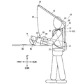
- FIG. 1 is a side view of an embodiment of a work assisting device according to the present invention attached to an operator, in which the arm support is a glove.
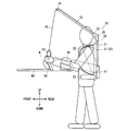
- FIG. 2 is a side view of another embodiment of the work assisting device according to the present invention attached to an operator, where the arm support is a cylindrical band.
- FIG. 3 is a side view of a further embodiment of the work assisting device according to the present invention attached to an operator, where the arm support is a grip.
- the work assisting device 10 is for reducing the load on the arm of the worker due to the load of the hand-held work machine W that the worker grips with his hand.
- the hand-held working machine W is a hedge trimmer as an example. Since the hedge trimmer W is a known hand-held work machine, detailed description thereof is omitted.
- the work assisting device 10 includes a body part mounting tool 20 to be mounted on the worker's body part, and extends upward from the body part mounting tool 20 and then forwards, with a tip above the worker's arm (hand, forearm). An arm 30, a wire 40 that hangs down from the tip of the arm 30, and an arm support 50 that is attached to the operator's arm and suspended by the wire 40.
- the torso part mounting tool 20 is attached to the operator's torso part (shoulder, chest, abdomen, back, etc.), and in this embodiment, has a harness structure that is carried by the operator.
- the body part mounting tool 20 includes a back pad part 21 to be mounted on the operator's back, a pair of left and right shoulder straps 22 provided on the back pad part 21, and a waist strap 23 provided below the back pad part 21. I have.
- the body part mounting tool 20 is not limited to the harness structure, and clothes such as a vest, a backpack or the like may be used as long as the body part mounting tool 20 is attached to the body part of the operator.
- An arm 30 and a spring balancer 41 are attached to the rear surface of the backrest portion 21 of the body portion mounting tool 20.
- the arm 30 is intended to hang the wire 40 from above the arm portion of the operator, and uses a hollow tube material through which the wire 40 is slidably inserted.
- the arm 30 includes a first arm portion 31 that is fixed to the rear surface of the backrest portion 21 and extends upward, and a second arm portion 32 that extends forward from the distal end portion of the first arm portion 31.
- the 1st arm part 31 and the 2nd arm part 32 can be expanded-contracted by a telescopic mechanism, for example.
- the upper part and the lower part of the first arm part 31 are fixed to the backrest part 21, and are difficult to tilt forward and backward.
- the 1st arm part 31 is extended from the lower part of the trunk
- the length of the 1st arm part 31 is the length in which the upper end part is located in a worker's head vicinity.
- the lower end portion of the first arm portion 31 is attached to the lower portion of the body portion mounting tool 20 so as to be rotatable about the longitudinal axis, and the upper portion of the first arm portion 31 extends upward from the right shoulder of the operator. You may do it.
- first arm portion 31 is rotatable about its axis
- second arm portion 32 is rotated about the axis of the first arm portion 31 on the left front side of the operator by the rotation of the first arm portion 31.
- the first arm portion 31 is preferably rotated within a range of 3 ° to the operator's face side and 20 ° to the opposite side of the operator's face when the direction in which the operator faces the front is 0 °.
- the second arm portion 32 is prevented from coming into contact with the worker and is not greatly displaced from the upper position of the worker's arm portion.
- the second arm portion 32 is rotatable about its axis, and the second arm portion 32 is preferably rotatable within a range of 30 ° or less.
- the second arm portion 32 is fixedly connected to the upper end portion of the first arm portion 31 via a mounting bracket 33.
- the second arm portion 32 extends obliquely upward from the upper end of the first arm portion 31, and the second arm portion 32 has a length when the arm is extended forward so that the worker is in a working posture.
- the tip of the second arm portion 32 is positioned above the arm portion of the operator.
- a pulley 34 is provided at the front end portion of the second arm portion 32 to improve the sliding of the sliding wire 40.
- a pulley 35 is also provided on the mounting bracket 33 that connects the first arm portion 31 and the second arm portion 32, and the pulley 35 allows the wire 40 to pass through the first arm portion and the second arm portion 32. Good.
- the arm 30 of this embodiment includes a first arm portion 31 and a second arm portion 32 connected to the tip portion of the first arm portion 31, but is not limited to this.
- the arm part 31 and the second arm part 32 may be integrally formed of one pipe material.
- the angle between the first arm portion 31 and the second arm portion 32 is not limited to an obtuse angle, and may be a right angle or an acute angle.
- the arm 30 may have an arc shape and extend from the backrest portion 21 to above the operator's arm portion in a curved shape.
- the wire 40 hangs the hedge trimmer W which is a hand-held work machine, and comes out of a spring balancer 41 provided at the lower rear portion of the backrest portion 21.
- the wire 40 coming out of the spring balancer 41 is inserted from the lower end opening of the first arm portion 31 into the inner hole of the first arm portion 31, and passes through the upper end opening of the first arm portion 31 and the rear end opening of the second arm portion 32. It passes through the front end opening of the second arm portion 32.
- the wire 40 hangs down from the front end portion of the second arm portion 32 to the front side of the operator, and is attached to the arm portion (forearm or hand) of the operator via a mounting bracket 42 such as a carabiner at the tip end portion of the wire 40.
- the arm support 50 to be attached is detachably connected.
- the arm support 50 in the embodiment of FIG. 1 is a glove that is worn on the hand of an operator.
- the spring balancer 41 pulls the wire 40 with a predetermined force corresponding to the weight of the hedge trimmer W. Note that the pulling force of the spring balancer 41 can be changed according to the weight of a hand-held work machine such as a hedge trimmer.
- the arm support 50 of the left hand of the operator is suspended from the front end of the second arm 32 by the wire 40, and the hedge trimmer W is mounted on the hand holding the front handle W2.
- the wire 40 is suspended from the front end portion of the second arm portion 32 via the support 50, and the operator can work without feeling a load due to the load of the gripped hedge trimmer W.
- the hedge trimmer W is not directly hung by the wire 40, but the arm portion of the worker holding the hedge trimmer W is hung by the arm support 50 attached to the hand of the worker.
- a pipe material is employed for the arm 30, and the wire 40 is slidably inserted into the arm 30, and the wire 40 is pulled to the body portion mounting tool 20 with a predetermined load.
- a spring balancer 41 was provided.
- the wire 40 can be pulled according to the load of the hedge trimmer W by the spring balancer 41, and the operator does not feel the load due to the load of the hedge trimmer W or the minimum necessary amount due to the load of the hedge trimmer W. Pruning can be done just by feeling the load. That is, by feeling a slight load of the handheld work machine, it is possible to work while feeling the operational feeling of the handheld work machine.
- the arm 30 includes a first arm portion 31 that extends upward from the backrest portion 21 of the body portion mounting tool 20, and a second arm that extends forward from the distal end portion of the first arm portion 31.
- the arm part 32 was provided, and both the 1st arm part 31 and the 2nd arm part 32 were made extensible. Thereby, it becomes possible to arrange
- the operator's arm can be suspended by the wire 40.
- both the first arm portion 31 and the second arm portion 32 are extendable.
- the present invention is not limited to this, but the effect is limited, but the first arm portion 31 is not limited thereto.
- only one of the second arm portions 32 may be telescopic.
- the body part mounting tool 20 is a harness having a back pad part 21 to be mounted on the operator's back, a shoulder strap 22 provided on the back pad part 21, and a waist strap 23.
- the structure When doing in this way, the operator can mount the body part mounting tool 20 without taking time and effort. Further, the shoulder strap 22 and the waist strap 23 prevent the back rest 21 from being separated from the operator's back, and the tip of the arm 30 fixed to the back rest 21 can be prevented from falling forward.
- a chest strap may be further provided on the body part mounting tool 20.
- a glove that is worn on the operator's hand is adopted as the arm support tool 50. Since the operator only wears the glove as the arm support 50 in his / her hand, the arm support 50 can be easily attached / detached.
- a cylindrical band attached to the operator's forearm (this may be the upper arm) may be adopted. Good. This band is not limited to a cylindrical band, and may be a band that is used by wrapping a cloth material around a forearm (or upper arm). Further, the shape of the band adopted for the arm support 50 may be a C-shaped cross section and a flexible band along the longitudinal direction of the arm.
- an annular grip that is gripped by the operator's hand may be employed.
- the operator works by gripping the grip as the arm support 50 together with the front handle W2 of the hedge trimmer W.
- the grip is not limited to an annular shape, and various shapes such as an L shape and a rod shape may be employed.
- the hedge trimmer has been described as an example of a handheld work machine.
- a handheld work machine used by a worker who is assisted by the work assistance device 10 of the present invention is a brush cutter.
- it may be a handheld gardening machine such as a chain saw, a handheld blower, or a gardening hair clipper, or a handheld electric tool (handheld working machine) such as a hammer, a hammer drill, or a driver.
- the work assisting device 10 of the present invention can reduce the load on the worker due to the load of the handheld work machine when the worker holds various types of handheld work machines. it can.
Abstract
A work aid device (10) includes the following: a torso harness (20) to be worn on the torso of a worker who is working using a handheld work device (W); an arm (30) that extends upward and forward from the torso harness (20) and that has a tip located above the arm of the worker; a wire (40) that hangs down from the tip of the arm (30); and an arm support (50) that dangles from the wire (40) and is to be worn on the arm of the worker. When the worker works using the handheld work device (W), the arm of the worker holding the handheld work device (W) is supported by the arm support (50).
Description
本発明は、手持ち式作業機を把持する作業者の腕部を支持するための作業補助装置に関し、より詳しくは、作業者が作業機を把持しているときに、腕部を支持するために作業者の腕部に装着されるべき作業者の上方からつり下げられた腕部支持具を備えてなり、それにより作業機を把持するために作業者の腕部に掛かる負荷を軽減する腕部支持装置に関する。
The present invention relates to a work assistance device for supporting an arm part of an operator who holds a hand-held work machine, and more particularly, to support an arm part when the worker is holding the work machine. An arm portion that includes an arm support that is suspended from above the worker to be mounted on the worker's arm portion, thereby reducing the load on the worker's arm portion to grip the work implement The present invention relates to a support device.
作業者が手で把持して作業する手持ち式作業機の荷重による手への負荷を減らすことを目的とした作業補助装置は、この技術分野において知られている。例えば、WO97/14540号公報は、作業者がショルダーストラップとウェストストラップとを用いて背負うハーネスと、ハーネスに装着されて作業者の前側上部まで延びる管状アームと、管状アーム内に摺動自在に挿通されて管状アームの前側上部から垂れ下がるワイヤと、ハーネスに装着されてワイヤを所定の荷重で引くスプリングバランサと、ワイヤの先端に設けられたフックとを備えてなる作業補助装置を開示している。この作業補助装置では、作業者が把持する手持ち式作業機をフックに引っ掛けることにより、手持ち式作業機は作業者の前でワイヤによって吊り下げられることになり、作業者が手持ち式作業機の荷重による手への負荷を受けないようにすることができる。
Work assist devices that are intended to reduce the load on the hand due to the load of a hand-held work machine that is held by the operator's hand are known in this technical field. For example, WO97 / 14540 discloses a harness that an operator carries with a shoulder strap and a waist strap, a tubular arm that is attached to the harness and extends to the upper front side of the operator, and is slidably inserted into the tubular arm. An operation assisting device is disclosed that includes a wire that hangs from the front upper portion of the tubular arm, a spring balancer that is attached to a harness and pulls the wire with a predetermined load, and a hook provided at the tip of the wire. In this work assisting device, the handheld work machine that is held by the worker is hooked on the hook, so that the handheld work machine is suspended by the wire in front of the worker, and the operator can load the load on the handheld work machine. It can be made not to receive the load on the hand by.
上記のPCT公報に記載の作業補助装置は、手持ち式作業機を作業者の前でワイヤによって吊り下げられるようにしているので、作業者は手持ち式作業機の荷重による負荷を手に感じずに作業をすることができる。しかし、作業者が手持ち式作業機を把持している手を離したときに、手持ち式作業機が作業者の前側で揺動しながら吊り下げられることになり、手持ち式作業機が作業者の方に向かって揺れて作業者に当たるおそれがあった。
The work assist device described in the above PCT publication allows the handheld work machine to be suspended by a wire in front of the worker, so that the worker does not feel the load caused by the load of the handheld work machine. Can work. However, when the worker releases the hand holding the handheld work machine, the handheld work machine is suspended while swinging in front of the worker, and the handheld work machine is There was a risk of swaying toward the operator.
本発明は、作業者の前側に上方からワイヤで作業機を吊り下げないで、手持ち式作業機で作業する作業者の腕部を支持する腕部支持具をワイヤで吊り下げることによって、作業機を把持するために作業者の腕部に掛かる負荷(作業者の腕に必要な力)を軽減するようにし、ワイヤに吊り下がった作業機が作業者の前側で揺れて作業者の体に当たることがないようにすることを目的とする。
The present invention does not suspend the work machine from above with a wire on the front side of the worker, and suspends the arm support that supports the arm part of the worker working on the hand-held work machine with the wire. The load applied to the operator's arm to grip the operator (the force required for the operator's arm) should be reduced, and the work implement suspended on the wire will sway in front of the operator and hit the operator's body. The purpose is to prevent the occurrence of
上記目的を達成するために、本発明は、手持ち式作業機で作業する作業者の胴体部に装着する胴体部装着具と、前記作業者の背部において前記胴体部装着具に連結され、前記胴体部装着具から上方および前方に延びて前記作業者の腕部の上方に先端を有するアームと、前記アームの先端から垂れ下がるワイヤと、前記作業者が前記手持ち式作業機を保持する際に前記作業者の腕部に装着されるべき前記ワイヤによって吊り下げられた腕部支持具とを備え、前記手持ち式作業機を保持する前記作業者の腕部が前記腕部支持具によって支持されるようにしたことを特徴とする作業補助装置を提供するものである。
In order to achieve the above object, the present invention provides a body part mounting tool to be mounted on a body part of an operator working on a hand-held work machine, and the body part connected to the body part mounting tool at a back part of the worker. An arm having a tip extending upward and forward from the mounting tool and having a tip above the worker's arm, a wire hanging from the tip of the arm, and the work when the worker holds the hand-held work machine. An arm support that is suspended by the wire to be mounted on the person's arm, and the arm of the operator holding the handheld work machine is supported by the arm support It is an object of the present invention to provide a work auxiliary device characterized by the above.
このように構成した作業補助装置では、手持ち式作業機を把持する作業者の腕部が、作業者の腕部に装着されワイヤによって吊り下げられた腕部支持具によって支持されるので、手持ち式作業機を保持するために作業者の腕に掛かる負荷が軽減され、作業者は、把持した作業機の荷重による腕への負荷を感じずに作業をすることができる。このとき、手持ち式作業機が作業者の手から離れる(ずり落ちる)と、手持ち式作業機はワイヤによって直接吊り下げられていないので地面に落下することになり、手持ち式作業機が作業者の前側で吊り下げられて揺れて作業者に当たるという事態にはならない。
In the work auxiliary device configured as described above, the arm portion of the worker who holds the hand-held work machine is supported by the arm support tool that is mounted on the arm portion of the worker and suspended by the wire. The load applied to the worker's arm to hold the work machine is reduced, and the worker can work without feeling the load on the arm due to the load of the gripped work machine. At this time, if the hand-held work machine moves away from the operator's hand (slids down), the hand-held work machine is not directly suspended by the wire and falls to the ground. It will not be a situation where it hangs and shakes and hits the worker.
本発明による作業補助装置は、さらに好ましくは、アームが中空の管材で出来ていて、、ワイヤの一部が中空の管材の中に摺動自在に挿通されていて、ワイヤに連結されていてワイヤを所定の荷重で引き、もって腕部支持具を上向きに引くスプリングバランサを胴体部装着具に設けて構成される。このようにしたときには、スプリングバランサにより手持ち式作業機の荷重に応じてワイヤを引くようにすることができる。また、スプリングバランサをアームの先端部に取り付けないで胴体部装着具に取り付けたので、アームの先端部が重くなるのを防ぐことができた。
In the work auxiliary device according to the present invention, more preferably, the arm is made of a hollow tube material, and a part of the wire is slidably inserted into the hollow tube material, and is connected to the wire. Is provided with a spring balancer for pulling the arm support tool upward with a predetermined load and pulling the arm support tool upward. When this is done, the wire can be pulled according to the load of the handheld work machine by the spring balancer. In addition, since the spring balancer was attached to the body mounting tool without being attached to the tip of the arm, it was possible to prevent the tip of the arm from becoming heavy.
本発明による作業補助装置は、さらに好ましくは、アームが胴体部装着具から上側に延びる第1アーム部と、第1アーム部の先端部から前方に延びる第2アーム部とを備え、第1アームと第2アームの少なくとも一方を伸縮自在として構成される。このようにしたときには、作業者の体格に応じて第2アーム部の先端部を作業者の腕部の適切な上方の位置に配置することが可能となる。
More preferably, the work assisting device according to the present invention includes a first arm part having an arm extending upward from the body part mounting tool, and a second arm part extending forward from a tip part of the first arm part. And at least one of the second arms is configured to be extendable. When it does in this way, it becomes possible to arrange | position the front-end | tip part of a 2nd arm part in the suitable upper position of an operator's arm part according to a worker's physique.
本発明による作業補助装置は、さらに好ましくは、胴体部装着具が、作業者の背中に装着される背当て部と、背当て部に設けたショルダーストラップとウェストストラップとを有するハーネスである。このようにしたときには、胴体部装着具を手間を掛けずに作業者の胴体部に装着することができる。
The work assisting device according to the present invention is more preferably a harness in which the body part mounting tool includes a back pad part to be mounted on an operator's back, a shoulder strap provided on the back pad part, and a waist strap. In such a case, the body part mounting tool can be mounted on the operator's body part without taking time and effort.
本発明による作業補助装置では、腕部支持具は、一実施形態として作業者の手に装着されるグローブとすることができる。また、腕部支持具は、他の実施形態として、作業者の前腕部に装着される筒形のバンドとすることができる。腕部装着具は、さらに他の実施形態として、作業者の手で握って装着されるグリップとすることができる。
In the work assistance device according to the present invention, the arm support may be a glove that is worn on the operator's hand as an embodiment. Moreover, an arm part support tool can be made into the cylindrical band with which an operator's forearm part is mounted | worn as other embodiment. As still another embodiment, the arm attachment device can be a grip that is attached by being gripped by an operator's hand.
図1は、作業者に装着された本発明による作業補助装置の一実施形態の側面図であり、腕部支持具がグローブである場合である。
FIG. 1 is a side view of an embodiment of a work assisting device according to the present invention attached to an operator, in which the arm support is a glove.
図2は、作業者に装着された本発明による作業補助装置の他の実施形態の側面図であり、腕部支持具が筒形のバンドである場合である。
FIG. 2 is a side view of another embodiment of the work assisting device according to the present invention attached to an operator, where the arm support is a cylindrical band.
図3は、作業者に装着された本発明による作業補助装置のさらなる実施形態の側面図であり、腕部支持具がグリップである場合である。
FIG. 3 is a side view of a further embodiment of the work assisting device according to the present invention attached to an operator, where the arm support is a grip.
以下、本発明の作業補助装置の一実施形態を添付図面を参照して説明する。図1に示したように、作業補助装置10は、作業者が手で把持して作業する手持ち式作業機Wの荷重による作業者の腕部への負荷を軽減するためのものである。この実施形態は、手持ち式作業機Wが一例としてヘッジトリマである場合について説明する。なお、ヘッジトリマWは公知の手持ち式作業機であるので詳細な説明を省略する。作業補助装置10は、作業者の胴体部に装着する胴体部装着具20と、胴体部装着具20から上方に延び次いで前方に延びて作業者の腕部(手、前腕)の上方に先端を有するアーム30と、アーム30の先端から垂れ下がるワイヤ40と、作業者の腕部に装着され、ワイヤ40によって吊り下げられた腕部支持具50とを備えている。
Hereinafter, an embodiment of the work assistance device of the present invention will be described with reference to the accompanying drawings. As shown in FIG. 1, the work assisting device 10 is for reducing the load on the arm of the worker due to the load of the hand-held work machine W that the worker grips with his hand. This embodiment demonstrates the case where the hand-held working machine W is a hedge trimmer as an example. Since the hedge trimmer W is a known hand-held work machine, detailed description thereof is omitted. The work assisting device 10 includes a body part mounting tool 20 to be mounted on the worker's body part, and extends upward from the body part mounting tool 20 and then forwards, with a tip above the worker's arm (hand, forearm). An arm 30, a wire 40 that hangs down from the tip of the arm 30, and an arm support 50 that is attached to the operator's arm and suspended by the wire 40.
胴体部装着具20は、作業者の胴体部(肩、胸、腹部、背中等)に装着されるものであり、この実施形態では作業者に背負われるハーネス構造のものである。胴体部装着具20は、作業者の背中に装着される背当て部21と、背当て部21に設けた左右一対のショルダーストラップ22と、背当て部21の下部に設けたウェストストラップ23とを備えている。なお、胴体部装着具20は、ハーネス構造に限られるものでなく、作業者の胴体部に装着されるものであれば、ベスト等の衣類、背負子等を用いてもよい。胴体部装着具20の背当て部21の後面には、アーム30とスプリングバランサ41が取り付けられている。
The torso part mounting tool 20 is attached to the operator's torso part (shoulder, chest, abdomen, back, etc.), and in this embodiment, has a harness structure that is carried by the operator. The body part mounting tool 20 includes a back pad part 21 to be mounted on the operator's back, a pair of left and right shoulder straps 22 provided on the back pad part 21, and a waist strap 23 provided below the back pad part 21. I have. The body part mounting tool 20 is not limited to the harness structure, and clothes such as a vest, a backpack or the like may be used as long as the body part mounting tool 20 is attached to the body part of the operator. An arm 30 and a spring balancer 41 are attached to the rear surface of the backrest portion 21 of the body portion mounting tool 20.
アーム30は、ワイヤ40を作業者の腕部の上方から垂れ下げることを目的としたものであり、中空の管材を用い、その中を通してワイヤ40が摺動可能に挿入されている。アーム30は、背当て部21の後面に固定されて上側に延びる第1アーム部31と、第1アーム部31の先端部から前方に延びる第2アーム部32とを備えている。第1アーム部31及び第2アーム部32は、例えば、テレスコピック機構によって伸縮自在としたものである。第1アーム部31は、上部及び下部が背当て部21に固定されており、前後に傾動しにくくなっている。第1アーム部31は、胴体部装着具20の下部から左斜め上側に延び、第1アーム部31の上部は、作業者の左肩より上に延びている。第1アーム部31の長さは、その上端部が作業者の頭部付近に位置する長さとなっている。第1アーム部31の下端部を胴体部装着具20の下部に前後方向の軸線回りに回動可能に取り付けるようにし、第1アーム部31の上部を作業者の右肩から上側に延出させるようにしてもよい。また、第1アーム部31は、その軸線回りに回動可能となっており、第1アーム部31の回動によって第2アーム部32が作業者の左前側において第1アーム部31の軸線回りに回動可能となっている。第1アーム部31は、作業者が正面を向く方向を0°としたときに、作業者の顔側に3°~作業者の顔と反対側に20°の範囲で回動させるのが好ましく、第1アーム部31の回動角度を規制することによって第2アーム部32が作業者に接触しないようになるとともに、作業者の腕部の上方位置から大きくずれないようになる。また、第2アーム部32は、その軸線回りに回動可能となっており、第2アーム部32を30°以下の範囲で回動可能とするのが好ましい。
The arm 30 is intended to hang the wire 40 from above the arm portion of the operator, and uses a hollow tube material through which the wire 40 is slidably inserted. The arm 30 includes a first arm portion 31 that is fixed to the rear surface of the backrest portion 21 and extends upward, and a second arm portion 32 that extends forward from the distal end portion of the first arm portion 31. The 1st arm part 31 and the 2nd arm part 32 can be expanded-contracted by a telescopic mechanism, for example. The upper part and the lower part of the first arm part 31 are fixed to the backrest part 21, and are difficult to tilt forward and backward. The 1st arm part 31 is extended from the lower part of the trunk | drum mounting tool 20 diagonally on the left, and the upper part of the 1st arm part 31 is extended above the operator's left shoulder. The length of the 1st arm part 31 is the length in which the upper end part is located in a worker's head vicinity. The lower end portion of the first arm portion 31 is attached to the lower portion of the body portion mounting tool 20 so as to be rotatable about the longitudinal axis, and the upper portion of the first arm portion 31 extends upward from the right shoulder of the operator. You may do it. Further, the first arm portion 31 is rotatable about its axis, and the second arm portion 32 is rotated about the axis of the first arm portion 31 on the left front side of the operator by the rotation of the first arm portion 31. Can be rotated. The first arm portion 31 is preferably rotated within a range of 3 ° to the operator's face side and 20 ° to the opposite side of the operator's face when the direction in which the operator faces the front is 0 °. By restricting the rotation angle of the first arm portion 31, the second arm portion 32 is prevented from coming into contact with the worker and is not greatly displaced from the upper position of the worker's arm portion. The second arm portion 32 is rotatable about its axis, and the second arm portion 32 is preferably rotatable within a range of 30 ° or less.
第1アーム部31の上側の先端部には、取付金具33を介して第2アーム部32が固定され連結されている。第2アーム部32は、第1アーム部31の上端から斜め上側の前方に延びており、第2アーム部32の長さは、作業者が作業姿勢となるように腕を前側に伸ばしたときに、第2アーム部32の先端が作業者の腕部の上方に位置するようになっている。第2アーム部32の前端部には、摺動するワイヤ40の滑りを良好とする滑車34が設けられている。また、第1アーム部31と第2アーム部32を連結する取付金具33にも滑車35が設けられており、滑車35は、第1アーム部及び第2アーム部32を通るワイヤ40の滑りを良好にしている。なお、この実施形態のアーム30は、第1アーム部31と、第1アーム部31の先端部に接続した第2アーム部32とからなるが、これに限られるものでなく、例えば、第1アーム部31と第2アーム部32とを1つの管材により一体的に形成したものであってもよい。また、第1アーム部31と第2アーム部32の間の角度を鈍角としたものに限られるものでなく、直角または鋭角としたものであってもよい。さらに、アーム30を円弧形として、背当て部21から作業者の腕部の上方まで曲線状に延び出させたものであってもよい。
The second arm portion 32 is fixedly connected to the upper end portion of the first arm portion 31 via a mounting bracket 33. The second arm portion 32 extends obliquely upward from the upper end of the first arm portion 31, and the second arm portion 32 has a length when the arm is extended forward so that the worker is in a working posture. In addition, the tip of the second arm portion 32 is positioned above the arm portion of the operator. A pulley 34 is provided at the front end portion of the second arm portion 32 to improve the sliding of the sliding wire 40. A pulley 35 is also provided on the mounting bracket 33 that connects the first arm portion 31 and the second arm portion 32, and the pulley 35 allows the wire 40 to pass through the first arm portion and the second arm portion 32. Good. The arm 30 of this embodiment includes a first arm portion 31 and a second arm portion 32 connected to the tip portion of the first arm portion 31, but is not limited to this. The arm part 31 and the second arm part 32 may be integrally formed of one pipe material. Further, the angle between the first arm portion 31 and the second arm portion 32 is not limited to an obtuse angle, and may be a right angle or an acute angle. Furthermore, the arm 30 may have an arc shape and extend from the backrest portion 21 to above the operator's arm portion in a curved shape.
ワイヤ40は、手持ち式作業機であるヘッジトリマWを吊り下げるものであり、背当て部21の後面下部に設けたスプリングバランサ41から出ている。スプリングバランサ41から出たワイヤ40は、第一アーム部31の下端開口から第1アーム部31の内孔に挿通され、第1アーム部31の上端開口及び第2アーム部32の後端開口を通って第2アーム部32の前端開口から出ている。ワイヤ40は、第2アーム部32の前端部から作業者の前側に垂れ下がっており、ワイヤ40の先端部にはカラビナ等の取付金具42を介して作業者の腕部(前腕または手)に装着される腕部支持具50が着脱可能に連結されている。図1の実施形態における腕部支持具50は、作業者の手に装着されるグローブである。スプリングバランサ41は、ワイヤ40をヘッジトリマWの重量に応じた所定の力で引くものである。なお、スプリングバランサ41は、ヘッジトリマ等の手持ち式作業機の重量に応じて引く力が変更可能となっている。
The wire 40 hangs the hedge trimmer W which is a hand-held work machine, and comes out of a spring balancer 41 provided at the lower rear portion of the backrest portion 21. The wire 40 coming out of the spring balancer 41 is inserted from the lower end opening of the first arm portion 31 into the inner hole of the first arm portion 31, and passes through the upper end opening of the first arm portion 31 and the rear end opening of the second arm portion 32. It passes through the front end opening of the second arm portion 32. The wire 40 hangs down from the front end portion of the second arm portion 32 to the front side of the operator, and is attached to the arm portion (forearm or hand) of the operator via a mounting bracket 42 such as a carabiner at the tip end portion of the wire 40. The arm support 50 to be attached is detachably connected. The arm support 50 in the embodiment of FIG. 1 is a glove that is worn on the hand of an operator. The spring balancer 41 pulls the wire 40 with a predetermined force corresponding to the weight of the hedge trimmer W. Note that the pulling force of the spring balancer 41 can be changed according to the weight of a hand-held work machine such as a hedge trimmer.
次に、作業者がこの発明の作業補助装置10を装着したときのヘッジトリマWを用いた作業について説明する。作業者が胴体部装着具20であるハーネスを装着し、ワイヤ40を引っ張って先端部の取付金具42を腕部支持具50である左手に装着したグローブに取り付ける。この状態で、作業者は、右手でヘッジトリマWの後部ハンドルW1を把持するとともに、左手で前部ハンドルW2を把持する。この状態で、作業者は右手で後部ハンドルW1に設けたトリガスイッチをオン操作すると、上下一対のシヤーブレードW3が互いに逆向きに前後に往復動し、シヤーブレードW3を生垣に当てることで、生垣の枝が互いに逆向きに往復動する上下一対のシヤーブレードW3によって切断される。このとき、作業者の左手の腕部支持具50は、ワイヤ40によって第2アーム部32の前端部から吊り下げられており、ヘッジトリマWは、前部ハンドルW2を把持した手に装着した腕部支持具50を介してワイヤ40によって第2アーム部32の前端部から吊り下げられることになり、作業者は、把持したヘッジトリマWの荷重による負荷を感じずに作業をすることができる。この作業補助装置10は、ヘッジトリマWをワイヤ40によって直接吊り下げるものでなく、ヘッジトリマWを把持する作業者の腕部を作業者が手に装着した腕部支持具50により吊り下げるようにしたものであるため、作業者の作業中にヘッジトリマWが作業者の手から滑り落ちても、ヘッジトリマWは作業者の前で吊り下げられずに地面に落下することになり、ヘッジトリマWが作業者の前側で吊り下げられて作業者に当たるという事態には至らないようになった。
Next, the work using the hedge trimmer W when the worker wears the work auxiliary device 10 of the present invention will be described. An operator wears the harness that is the body attachment device 20 and pulls the wire 40 to attach the attachment fitting 42 at the distal end to the glove that is attached to the left hand that is the arm support 50. In this state, the operator holds the rear handle W1 of the hedge trimmer W with the right hand and holds the front handle W2 with the left hand. In this state, when the operator turns on the trigger switch provided on the rear handle W1 with the right hand, the pair of upper and lower shear blades W3 reciprocate back and forth in opposite directions, and hit the shear blade W3 against the hedge. Are cut by a pair of upper and lower shear blades W3 that reciprocate in opposite directions. At this time, the arm support 50 of the left hand of the operator is suspended from the front end of the second arm 32 by the wire 40, and the hedge trimmer W is mounted on the hand holding the front handle W2. The wire 40 is suspended from the front end portion of the second arm portion 32 via the support 50, and the operator can work without feeling a load due to the load of the gripped hedge trimmer W. In this work assisting device 10, the hedge trimmer W is not directly hung by the wire 40, but the arm portion of the worker holding the hedge trimmer W is hung by the arm support 50 attached to the hand of the worker. Therefore, even if the hedge trimmer W slides down from the operator's hand during the work of the worker, the hedge trimmer W falls to the ground without being suspended in front of the worker, and the hedge trimmer W It is no longer possible to hang on the front side and hit the worker.
ここに説明した作業補助装置10においては、アーム30に管材が採用され、ワイヤ40をアーム30内に摺動自在に挿通するようにし、胴体部装着具20にはワイヤ40を所定の荷重で引くスプリングバランサ41を設けた。これにより、スプリングバランサ41によってヘッジトリマWの荷重に応じてワイヤ40を引くようにすることができ、作業者はヘッジトリマWの荷重による負荷を感じないで、または、ヘッジトリマWの荷重による必要最低限の負荷を感じるだけで剪定の作業をすることができる。すなわち、手持ち式作業機の荷重のごく僅かを感じるようにすることにより、手持ち式作業機の操作感を感じながら作業をすることができる。
In the work assisting device 10 described here, a pipe material is employed for the arm 30, and the wire 40 is slidably inserted into the arm 30, and the wire 40 is pulled to the body portion mounting tool 20 with a predetermined load. A spring balancer 41 was provided. Thus, the wire 40 can be pulled according to the load of the hedge trimmer W by the spring balancer 41, and the operator does not feel the load due to the load of the hedge trimmer W or the minimum necessary amount due to the load of the hedge trimmer W. Pruning can be done just by feeling the load. That is, by feeling a slight load of the handheld work machine, it is possible to work while feeling the operational feeling of the handheld work machine.
ここに説明した作業補助装置10においては、アーム30は、胴体部装着具20の背当て部21から上側に延びる第1アーム部31と、第1アーム部31の先端部から前方に延びる第2アーム部32とを備え、第1アーム部31と第2アーム部32の両方を伸縮自在とした。これにより、作業者の体格に応じて第2アーム部32の先端部を作業者の手の上側に適切に配置することが可能となり、作業者の前側の使用しやすい位置でヘッジトリマWを把持する作業者の腕部をワイヤ40によって吊り下げることができるようになった。なお、この実施形態では、第1アーム部31及び第2アーム部32の両方を伸縮自在としたが、本発明はこれに限られるものでなく、効果は限定的となるが第1アーム部31または第2アーム部32の一方のみを伸縮自在としてもよい。
In the work auxiliary device 10 described here, the arm 30 includes a first arm portion 31 that extends upward from the backrest portion 21 of the body portion mounting tool 20, and a second arm that extends forward from the distal end portion of the first arm portion 31. The arm part 32 was provided, and both the 1st arm part 31 and the 2nd arm part 32 were made extensible. Thereby, it becomes possible to arrange | position the front-end | tip part of the 2nd arm part 32 appropriately above an operator's hand according to a worker's physique, and hold | grip the hedge trimmer W in the position which is easy to use on the operator's front side. The operator's arm can be suspended by the wire 40. In this embodiment, both the first arm portion 31 and the second arm portion 32 are extendable. However, the present invention is not limited to this, but the effect is limited, but the first arm portion 31 is not limited thereto. Alternatively, only one of the second arm portions 32 may be telescopic.
ここに説明した作業補助装置10においては、胴体部装着具20は、作業者の背中に装着される背当て部21と、背当て部21に設けたショルダーストラップ22とウェストストラップ23とを有するハーネス構造とした。このようにしたときには、作業者は、胴体部装着具20を手間を掛けずに装着することができる。また、ショルダーストラップ22とウェストストラップ23とによって、背当て部21が作業者の背中から離れないようになり、背当て部21に固定したアーム30の先端部が前方に倒れにくくすることができた。なお、胴体部装着具20にはさらにチェストストラップを設けるようにしてもよい。
In the work assistance device 10 described here, the body part mounting tool 20 is a harness having a back pad part 21 to be mounted on the operator's back, a shoulder strap 22 provided on the back pad part 21, and a waist strap 23. The structure. When doing in this way, the operator can mount the body part mounting tool 20 without taking time and effort. Further, the shoulder strap 22 and the waist strap 23 prevent the back rest 21 from being separated from the operator's back, and the tip of the arm 30 fixed to the back rest 21 can be prevented from falling forward. . Note that a chest strap may be further provided on the body part mounting tool 20.
以上に説明した作業補助具10においては、腕部支持具50として作業者の手に装着されるグローブを採用している。作業者は、腕部支持具50としてのグローブを手に装着するだけであるので、腕部支持具50を簡単に着脱できる。また、腕部支持具50の他の実施形態として、図2に示したように、作業者の前腕(これは、上腕であってもよい)に装着される筒形のバンドを採用してもよい。なお、このバンドは、筒形のバンドに限られるものでなく、布材を前腕(または上腕)に巻き付けて使用するバンドであってもよい。また、腕部支持具50に採用したバンドの形状を断面C形で腕の長手方向に沿った可撓性のバンドを採用したものであってもよい。さらに、腕部支持具50の他の実施形態として、図3に示したように、作業者の手で握る環状のグリップを採用してもよい。腕部支持具50にグリップを採用したときには、作業者は、ヘッジトリマWの前部ハンドルW2とともに腕部支持具50としてのグリップを把持して作業をする。なお、グリップは、環状に限られるものでなく、L形、棒状等の種々の形状を採用してもよい。
In the work auxiliary tool 10 described above, a glove that is worn on the operator's hand is adopted as the arm support tool 50. Since the operator only wears the glove as the arm support 50 in his / her hand, the arm support 50 can be easily attached / detached. Further, as another embodiment of the arm support 50, as shown in FIG. 2, a cylindrical band attached to the operator's forearm (this may be the upper arm) may be adopted. Good. This band is not limited to a cylindrical band, and may be a band that is used by wrapping a cloth material around a forearm (or upper arm). Further, the shape of the band adopted for the arm support 50 may be a C-shaped cross section and a flexible band along the longitudinal direction of the arm. Furthermore, as another embodiment of the arm support 50, as shown in FIG. 3, an annular grip that is gripped by the operator's hand may be employed. When a grip is employed for the arm support 50, the operator works by gripping the grip as the arm support 50 together with the front handle W2 of the hedge trimmer W. The grip is not limited to an annular shape, and various shapes such as an L shape and a rod shape may be employed.
上記の実施形態においては、手持ち式作業機の一例としてヘッジトリマを用いて説明したが、本発明の作業補助装置10により補助される作業者が使用する手持ち式作業機の他の例は、刈払機、チェーンソー、手持ち式ブロワ、園芸用バリカン等の手持ち式園芸作業機であってもよいし、ハンマ、ハンマドリル、ドライバ等の手持ち式電動工具(手持ち式作業機)であってもよい。以上の説明から理解できるように、この発明の作業補助装置10は、作業者が様々な種類の手持ち式作業機を把持したときの手持ち式作業機の荷重による作業者への負荷を減らすことができる。
In the above embodiment, the hedge trimmer has been described as an example of a handheld work machine. However, another example of a handheld work machine used by a worker who is assisted by the work assistance device 10 of the present invention is a brush cutter. Further, it may be a handheld gardening machine such as a chain saw, a handheld blower, or a gardening hair clipper, or a handheld electric tool (handheld working machine) such as a hammer, a hammer drill, or a driver. As can be understood from the above description, the work assisting device 10 of the present invention can reduce the load on the worker due to the load of the handheld work machine when the worker holds various types of handheld work machines. it can.
Claims (7)
- 手持ち式作業機で作業する作業者の胴体部に装着する胴体部装着具と、
前記作業者の背部において前記胴体部装着具に連結され、前記胴体部装着具から上方および前方に延びて前記作業者の腕部の上方に先端を有するアームと、
前記アームの先端から垂れ下がるワイヤと、
前記作業者が前記手持ち式作業機を保持する際に前記作業者の腕部に装着されるべき前記ワイヤによって吊り下げられた腕部支持具とを備え、
前記手持ち式作業機を保持する前記作業者の腕部が前記腕部支持具によって支持されるようにしたことを特徴とする作業補助装置。 A torso mounting tool to be mounted on the torso of an operator working on a handheld work machine;
An arm connected to the body part mounting tool at the back of the worker, extending upward and forward from the body part mounting tool, and having a tip above the arm part of the worker;
A wire hanging from the tip of the arm;
An arm support that is suspended by the wire to be attached to the arm of the operator when the operator holds the handheld work machine,
A work assisting device, wherein an arm portion of the worker holding the hand-held work machine is supported by the arm portion support tool. - 請求項1に記載の作業補助具において、
前記アームは、中空の管材で出来ており、
前記ワイヤは、その一部が前記中空の管材の中に摺動自在に挿通されており、
前記胴体部装着具には、前記ワイヤに連結され前記ワイヤを所定の荷重で引き、もって前記腕部支持具を上向きに引くスプリングバランサを設けた
ことを特徴とする作業補助装置。 The work auxiliary tool according to claim 1,
The arm is made of a hollow tube,
A part of the wire is slidably inserted into the hollow tube material,
The body support device is provided with a work balance device which is connected to the wire and is provided with a spring balancer which pulls the wire with a predetermined load and pulls the arm support tool upward. - 請求項1または2に記載の作業補助具において、
前記アームは、前記胴体部装着具から上側に延びる第1アーム部と、前記第1アーム部の先端部から前方に延びる第2アーム部とを備え、前記第1アームと前記第2アームの少なくとも一方を伸縮自在としたことを特徴とする作業補助装置。 In the work assistance tool according to claim 1 or 2,
The arm includes a first arm part extending upward from the body part mounting tool, and a second arm part extending forward from a distal end part of the first arm part, and at least one of the first arm and the second arm. A work auxiliary device characterized in that one of the two is extendable. - 請求項1~3の何れか1項に記載の作業補助装置において、
前記胴体部装着具は、作業者の背中に装着される背当て部と、前記背当て部に接続されたショルダーストラップとウェストストラップとを有するハーネス構造であることを特徴とする作業補助装置。 The work auxiliary device according to any one of claims 1 to 3,
The said body part mounting tool is a work assistance apparatus characterized by the harness structure which has a back support part with which a worker's back is mounted | worn, a shoulder strap connected to the said back support part, and a waist strap. - 請求項1~4の何れか1項に記載の作業補助装置において、
前記腕部支持具は、前記作業者の手に装着されるグローブとしたことを特徴とする作業補助装置。 The work auxiliary device according to any one of claims 1 to 4,
The work support device according to claim 1, wherein the arm support tool is a glove to be worn on the hand of the worker. - 請求項1~4の何れか1項に記載の作業補助装置において、
前記腕部支持具は、前記作業者の前腕部に装着される筒形のバンドとしたことを特徴とする作業補助装置。 The work auxiliary device according to any one of claims 1 to 4,
The work support device according to claim 1, wherein the arm support is a cylindrical band attached to the forearm of the worker. - 請求項1~4の何れか1項に記載の作業補助装置において、
前記腕部支持具は、前記作業者の手で握って装着されるグリップとしたことを特徴とする作業補助装置。 The work auxiliary device according to any one of claims 1 to 4,
The work support device according to claim 1, wherein the arm support is a grip that is gripped and attached by the operator's hand.
Applications Claiming Priority (2)
| Application Number | Priority Date | Filing Date | Title |
|---|---|---|---|
| JP2015-247375 | 2015-12-18 | ||
| JP2015247375A JP2017109290A (en) | 2015-12-18 | 2015-12-18 | Work supporting tool |
Publications (1)
| Publication Number | Publication Date |
|---|---|
| WO2017104534A1 true WO2017104534A1 (en) | 2017-06-22 |
Family
ID=59056456
Family Applications (1)
| Application Number | Title | Priority Date | Filing Date |
|---|---|---|---|
| PCT/JP2016/086552 WO2017104534A1 (en) | 2015-12-18 | 2016-12-08 | Work aid device |
Country Status (2)
| Country | Link |
|---|---|
| JP (1) | JP2017109290A (en) |
| WO (1) | WO2017104534A1 (en) |
Families Citing this family (1)
| Publication number | Priority date | Publication date | Assignee | Title |
|---|---|---|---|---|
| WO2018193817A1 (en) * | 2017-04-19 | 2018-10-25 | 株式会社マキタ | Auxiliary work tool |
Citations (3)
| Publication number | Priority date | Publication date | Assignee | Title |
|---|---|---|---|---|
| US4483070A (en) * | 1982-09-21 | 1984-11-20 | Joane G. Tannehill | Portable backpacked cutter |
| WO1996015404A1 (en) * | 1994-11-14 | 1996-05-23 | Thompson Michael William Fleet | Body-mounted stabilising apparatus for a camera |
| JP2013052192A (en) * | 2011-09-06 | 2013-03-21 | Wakayama Univ | Power assist robotic device and control method of the same |
-
2015
- 2015-12-18 JP JP2015247375A patent/JP2017109290A/en active Pending
-
2016
- 2016-12-08 WO PCT/JP2016/086552 patent/WO2017104534A1/en active Application Filing
Patent Citations (3)
| Publication number | Priority date | Publication date | Assignee | Title |
|---|---|---|---|---|
| US4483070A (en) * | 1982-09-21 | 1984-11-20 | Joane G. Tannehill | Portable backpacked cutter |
| WO1996015404A1 (en) * | 1994-11-14 | 1996-05-23 | Thompson Michael William Fleet | Body-mounted stabilising apparatus for a camera |
| JP2013052192A (en) * | 2011-09-06 | 2013-03-21 | Wakayama Univ | Power assist robotic device and control method of the same |
Also Published As
| Publication number | Publication date |
|---|---|
| JP2017109290A (en) | 2017-06-22 |
Similar Documents
| Publication | Publication Date | Title |
|---|---|---|
| JP6145866B2 (en) | Work support device | |
| JP4940090B2 (en) | Brush cutter | |
| WO2008147259A1 (en) | Harness for power tool having a pole | |
| JP6205075B1 (en) | Grabber | |
| WO2002096238A1 (en) | Carrier device for an engine powered tool | |
| WO2017104534A1 (en) | Work aid device | |
| JP5306027B2 (en) | Indirect hot tool support | |
| JP7182418B2 (en) | motion support device | |
| CN103118529A (en) | Handle arrangement for a power tool | |
| US20070022572A1 (en) | Tool handle | |
| JP2016067299A (en) | Portable work machine | |
| US3327788A (en) | Harness for earth boring machine | |
| JP3221249U (en) | Work assist device | |
| KR100804365B1 (en) | Auxiliary equipment for a power mower | |
| US20120074185A1 (en) | Hose and cord buddy | |
| JP5139474B2 (en) | Power cord support | |
| JP2011160717A (en) | Shoulder belt for portable brush cutter | |
| JP2006197858A (en) | Rod supporting tool and rod butt grip | |
| FI127271B (en) | The cutter arrangement | |
| KR102356116B1 (en) | Wristband-type tool fall prevention device | |
| JP6173934B2 (en) | Power cord holder | |
| US20190210180A1 (en) | Extension operating device for power tools | |
| JP3164550B2 (en) | Drill aid | |
| WO1997014540A1 (en) | A device for supporting hand-held machine-driven tools | |
| KR20130059712A (en) | Muscular power supporting apparatus for wearing human body |
Legal Events
| Date | Code | Title | Description |
|---|---|---|---|
| 121 | Ep: the epo has been informed by wipo that ep was designated in this application |
Ref document number: 16875514 Country of ref document: EP Kind code of ref document: A1 |
|
| NENP | Non-entry into the national phase |
Ref country code: DE |
|
| 122 | Ep: pct application non-entry in european phase |
Ref document number: 16875514 Country of ref document: EP Kind code of ref document: A1 |