WO2017101079A1 - 一种基于无线通信模块的云接入方法和系统 - Google Patents
一种基于无线通信模块的云接入方法和系统 Download PDFInfo
- Publication number
- WO2017101079A1 WO2017101079A1 PCT/CN2015/097741 CN2015097741W WO2017101079A1 WO 2017101079 A1 WO2017101079 A1 WO 2017101079A1 CN 2015097741 W CN2015097741 W CN 2015097741W WO 2017101079 A1 WO2017101079 A1 WO 2017101079A1
- Authority
- WO
- WIPO (PCT)
- Prior art keywords
- wireless communication
- communication module
- thread
- data
- message
- Prior art date
- Legal status (The legal status is an assumption and is not a legal conclusion. Google has not performed a legal analysis and makes no representation as to the accuracy of the status listed.)
- Ceased
Links
Images


Classifications
-
- H—ELECTRICITY
- H04—ELECTRIC COMMUNICATION TECHNIQUE
- H04L—TRANSMISSION OF DIGITAL INFORMATION, e.g. TELEGRAPHIC COMMUNICATION
- H04L69/00—Network arrangements, protocols or services independent of the application payload and not provided for in the other groups of this subclass
- H04L69/08—Protocols for interworking; Protocol conversion
-
- H—ELECTRICITY
- H04—ELECTRIC COMMUNICATION TECHNIQUE
- H04L—TRANSMISSION OF DIGITAL INFORMATION, e.g. TELEGRAPHIC COMMUNICATION
- H04L67/00—Network arrangements or protocols for supporting network services or applications
- H04L67/01—Protocols
- H04L67/10—Protocols in which an application is distributed across nodes in the network
-
- H—ELECTRICITY
- H04—ELECTRIC COMMUNICATION TECHNIQUE
- H04L—TRANSMISSION OF DIGITAL INFORMATION, e.g. TELEGRAPHIC COMMUNICATION
- H04L12/00—Data switching networks
- H04L12/28—Data switching networks characterised by path configuration, e.g. LAN [Local Area Networks] or WAN [Wide Area Networks]
- H04L12/2803—Home automation networks
-
- H—ELECTRICITY
- H04—ELECTRIC COMMUNICATION TECHNIQUE
- H04L—TRANSMISSION OF DIGITAL INFORMATION, e.g. TELEGRAPHIC COMMUNICATION
- H04L12/00—Data switching networks
- H04L12/28—Data switching networks characterised by path configuration, e.g. LAN [Local Area Networks] or WAN [Wide Area Networks]
- H04L12/2803—Home automation networks
- H04L12/2807—Exchanging configuration information on appliance services in a home automation network
- H04L12/2809—Exchanging configuration information on appliance services in a home automation network indicating that an appliance service is present in a home automation network
-
- H—ELECTRICITY
- H04—ELECTRIC COMMUNICATION TECHNIQUE
- H04L—TRANSMISSION OF DIGITAL INFORMATION, e.g. TELEGRAPHIC COMMUNICATION
- H04L12/00—Data switching networks
- H04L12/28—Data switching networks characterised by path configuration, e.g. LAN [Local Area Networks] or WAN [Wide Area Networks]
- H04L12/2803—Home automation networks
- H04L12/283—Processing of data at an internetworking point of a home automation network
-
- H—ELECTRICITY
- H04—ELECTRIC COMMUNICATION TECHNIQUE
- H04L—TRANSMISSION OF DIGITAL INFORMATION, e.g. TELEGRAPHIC COMMUNICATION
- H04L67/00—Network arrangements or protocols for supporting network services or applications
- H04L67/01—Protocols
- H04L67/12—Protocols specially adapted for proprietary or special-purpose networking environments, e.g. medical networks, sensor networks, networks in vehicles or remote metering networks
- H04L67/125—Protocols specially adapted for proprietary or special-purpose networking environments, e.g. medical networks, sensor networks, networks in vehicles or remote metering networks involving control of end-device applications over a network
-
- H—ELECTRICITY
- H04—ELECTRIC COMMUNICATION TECHNIQUE
- H04L—TRANSMISSION OF DIGITAL INFORMATION, e.g. TELEGRAPHIC COMMUNICATION
- H04L67/00—Network arrangements or protocols for supporting network services or applications
- H04L67/50—Network services
- H04L67/55—Push-based network services
-
- H—ELECTRICITY
- H04—ELECTRIC COMMUNICATION TECHNIQUE
- H04L—TRANSMISSION OF DIGITAL INFORMATION, e.g. TELEGRAPHIC COMMUNICATION
- H04L67/00—Network arrangements or protocols for supporting network services or applications
- H04L67/50—Network services
- H04L67/56—Provisioning of proxy services
- H04L67/565—Conversion or adaptation of application format or content
-
- H—ELECTRICITY
- H04—ELECTRIC COMMUNICATION TECHNIQUE
- H04L—TRANSMISSION OF DIGITAL INFORMATION, e.g. TELEGRAPHIC COMMUNICATION
- H04L67/00—Network arrangements or protocols for supporting network services or applications
- H04L67/50—Network services
- H04L67/60—Scheduling or organising the servicing of application requests, e.g. requests for application data transmissions using the analysis and optimisation of the required network resources
-
- H—ELECTRICITY
- H04—ELECTRIC COMMUNICATION TECHNIQUE
- H04W—WIRELESS COMMUNICATION NETWORKS
- H04W28/00—Network traffic management; Network resource management
- H04W28/02—Traffic management, e.g. flow control or congestion control
- H04W28/10—Flow control between communication endpoints
- H04W28/14—Flow control between communication endpoints using intermediate storage
-
- H—ELECTRICITY
- H04—ELECTRIC COMMUNICATION TECHNIQUE
- H04L—TRANSMISSION OF DIGITAL INFORMATION, e.g. TELEGRAPHIC COMMUNICATION
- H04L12/00—Data switching networks
- H04L12/28—Data switching networks characterised by path configuration, e.g. LAN [Local Area Networks] or WAN [Wide Area Networks]
- H04L12/2803—Home automation networks
- H04L2012/2847—Home automation networks characterised by the type of home appliance used
- H04L2012/285—Generic home appliances, e.g. refrigerators
-
- H—ELECTRICITY
- H04—ELECTRIC COMMUNICATION TECHNIQUE
- H04L—TRANSMISSION OF DIGITAL INFORMATION, e.g. TELEGRAPHIC COMMUNICATION
- H04L45/00—Routing or path finding of packets in data switching networks
- H04L45/302—Route determination based on requested QoS
- H04L45/306—Route determination based on the nature of the carried application
-
- H—ELECTRICITY
- H04—ELECTRIC COMMUNICATION TECHNIQUE
- H04W—WIRELESS COMMUNICATION NETWORKS
- H04W84/00—Network topologies
- H04W84/02—Hierarchically pre-organised networks, e.g. paging networks, cellular networks, WLAN [Wireless Local Area Network] or WLL [Wireless Local Loop]
- H04W84/10—Small scale networks; Flat hierarchical networks
- H04W84/12—WLAN [Wireless Local Area Networks]
Definitions
- the present invention relates to the field of communications technologies, and in particular, to a cloud access method and system based on a wireless communication module.
- cloud server is based on resource sharing to reduce costs and improve the efficiency of flexible expansion of IT infrastructure.
- the construction of cloud servers is aimed at providing services to users on demand.
- the cloud server carries a large number of important business systems and data, and different home appliances need to access the cloud server to provide related services to users.
- the present invention aims to solve at least one of the technical problems in the related art to some extent.
- an object of the present invention is to provide a cloud access method based on a wireless communication module, which can connect a home appliance with a corresponding cloud server, realize access of a home appliance and multiple cloud servers, and effectively improve wireless communication.
- the cloud access effect of the module is to provide a cloud access method based on a wireless communication module, which can connect a home appliance with a corresponding cloud server, realize access of a home appliance and multiple cloud servers, and effectively improve wireless communication.
- Another object of the present invention is to provide a cloud access system based on a wireless communication module.
- a cloud access method based on a wireless communication module includes: receiving, by a wireless communication module, a first type of packet sent by a cloud server, and acquiring type information of the cloud server,
- the wireless communication module is connected to a plurality of cloud servers; the wireless communication module invokes a corresponding conversion protocol according to the type information of the cloud server; and the wireless communication module sets the first according to the conversion protocol.
- the type message is converted into a second type of message, and the second type of message is sent to the corresponding home appliance.
- the wireless communication module receives the first type of packet sent by the cloud server, and acquires the type information of the cloud server, where the wireless communication module and the plurality of The cloud server is connected; the wireless communication module invokes the corresponding conversion protocol according to the type information of the cloud server; and the wireless communication module converts the first type of message into the second type of message according to the conversion protocol, and sends the second type of message to the
- the corresponding home appliance can connect the home appliance with the corresponding cloud server, realize the access of the home appliance and the plurality of cloud servers, and effectively improve the cloud access effect based on the wireless communication module.
- a cloud access system based on a wireless communication module includes: a wireless communication module, a cloud server and a home appliance that communicate with each other through the wireless communication module, wherein the wireless The communication module includes: a serial port data transceiving thread for communicating with the home appliance; and a network data transceiving thread, And communicating with the cloud server; the service logic thread is configured to exchange messages with the serial port data sending and receiving thread and the network data sending and receiving thread, to send and receive the serial port data sending and receiving thread and the network data sending and receiving thread.
- the main thread is configured to control the serial port data sending and receiving thread, the network data sending and receiving thread, and the service logic thread; and applying an event callback submodule, wherein the main thread passes the application event callback
- the module controls the business logic thread; and an application event message queue, configured to receive an event message and read by the main thread, wherein the event message includes an application event message and a WIFI callback event message; and the state machine event distribution process a sub-module, configured to distribute the event message to a corresponding state machine according to a mode attribute of the event message, where the mode attribute is any one of AP-Mode, STA-Mode, or System, and is read.
- the cloud access system based on the wireless communication module proposed by the second aspect of the present invention exchanges messages with the serial port data sending and receiving thread and the network data sending and receiving thread through the service logic thread, and sends and receives the serial port data sending and receiving thread and the network data sending and receiving thread.
- the message is controlled, and the main thread controls the serial port data sending and receiving thread, the network data sending and receiving thread and the business logic thread, can realize the coordinated operation of multiple threads, effectively improve the thread scheduling effect in the cloud server access process, and facilitate the late wireless communication module. Functional extension of the hardware system.
- the mechanism controls the state of the wireless communication module to switch, and can realize the cooperative operation of the three state machines in the wireless communication module of the home appliance, thereby effectively improving the state management effect of the wireless communication module.
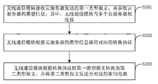
- FIG. 1 is a schematic flowchart of a cloud access method based on a wireless communication module according to an embodiment of the present invention
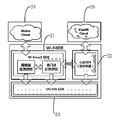
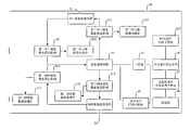
- FIG. 2 is a schematic structural diagram of hardware of a wireless communication module according to an embodiment of the present invention.
- FIG. 3 is a schematic diagram of a message exchange process of a wireless communication module according to an embodiment of the present invention.
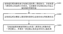
- FIG. 4 is a schematic flowchart of a cloud access method based on a wireless communication module according to another embodiment of the present invention.
- FIG. 5 is a schematic structural diagram of a wireless communication module according to another embodiment of the present invention.
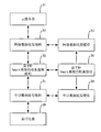
- FIG. 6 is a schematic flowchart of a method for managing a state machine of a wireless communication module by a main thread according to another embodiment of the present invention.
- FIG. 7 is a flow chart of a method for managing a state machine of a wireless communication module by a main thread according to another embodiment of the present invention.
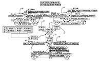
- FIG. 8 is a schematic diagram of state switching of a wireless communication module according to an embodiment of the present invention.
- FIG. 9 is a schematic structural diagram of a cloud access system based on a wireless communication module according to another embodiment of the present invention.
- the cloud access method based on a wireless communication module includes:
- the wireless communication module receives the first type of the packet sent by the cloud server, and obtains the type information of the cloud server, where the wireless communication module is connected to the plurality of cloud servers.
- cloud server is based on resource sharing to reduce costs while improving the efficiency of flexible expansion of IT infrastructure.
- the construction of cloud servers is aimed at providing services to users on demand.
- the cloud server carries a large number of important business systems and data.
- different home appliances need to access the cloud server to provide related services to users. Therefore, there are many requirements and challenges for cloud server access. Therefore, it is necessary to realize convenient and efficient access of home appliances and multiple cloud servers.
- the wireless communication module is specifically a wireless WIFI communication module.
- the wireless WIFI communication module supports Wi-Fi technology for household appliances.
- Household appliances such as air conditioners, refrigerators, and water heaters.
- an Asymmetric Digital Subscriber Line (ADSL), a cell broadband, or the like in a user's home can connect to a wireless communication module by using a home Wi-Fi technology to implement wireless access of the mobile terminal.
- ADSL Asymmetric Digital Subscriber Line
- a cell broadband or the like in a user's home
- a wireless communication module by using a home Wi-Fi technology to implement wireless access of the mobile terminal.
- the user may also interconnect the home appliance with the corresponding cloud server by using the wireless communication module to implement resource sharing between the home appliance and the cloud server.
- FIG. 2 is a schematic diagram of a hardware structure of a wireless communication module in an embodiment of the present invention
- FIG. 2 is an example of a cloud and a millet cloud in which a cloud server is beautiful.
- Figure 2 includes the M-Smart Software Development Kit (SDK) 21, the Huawei SDK 22, the vendor's underlying SDK 23, the US Cloud 24, and the Huawei Cloud 25.
- the M-Smart SDK 21 is used to implement the processing logic of the business logic thread based on the M-Smart system
- the Huawei SDK 22 is used to implement the protocol in the protocol conversion file xm_profile.c of Huawei Cloud 25, and the vendor underlying SDK 23 is used to implement the wireless communication module.
- the underlying hardware logic, Midea Cloud 24 and Xiaomi Cloud 25 are used to provide cloud service resources.
- the cloud server is a simple, efficient, secure and reliable computing service with flexible processing capabilities.
- the cloud server is used to provide comprehensive Internet service capabilities to various Internet users.
- Cloud servers such as Midea Cloud, Jingdong Cloud, Facebook Cloud, or Huawei Cloud.
- the cloud server has intelligent cloud access, intelligent cloud storage, and intelligent information push.
- the cloud server can push the resource to the home appliance, and the user can control the home appliance through the application program of the home appliance in the mobile terminal.
- microwave ovens in the United States has newly developed cooking recipe resources.
- Microwave oven manufacturers store the newly developed cooking recipe resources in the cloud cloud of intelligent cloud storage.
- wireless communication module When users use the wireless communication module to interconnect the beautiful microwave oven with the beautiful cloud.
- Midea Cloud will push the newly developed cooking recipe resources to the US microwave oven, so that users can control the US microwave oven to implement newly developed cooking recipe resources through the application of the microwave oven in the mobile terminal.
- the message is a data unit exchanged and transmitted in the network, that is, a data block to be sent by the station at one time.
- the message contains the complete data information to be sent, the length of which is inconsistent, the length is not limited and the length is variable.
- the type information of the cloud server may be, for example, a cloud ID, and different cloud IDs may be used to identify different cloud servers.
- the cloud ID may be set in a packet header of the first type of packet, which may be a packet header.
- the reserved field in the present invention may also be set in other fields, which is not specifically limited in this embodiment of the present invention.
- FIG. 3 it is a schematic diagram of a message exchange process of a wireless communication module according to an embodiment of the present invention. Including: serial data transmission and reception thread 31, business logic thread 32 based on M-Smart system, network data transmission and reception thread 33, serial data transmission and reception buffer 34, network data transmission and reception buffer 35, conversion protocol based on M-Smart system 36, cloud server 37 And household appliances 38.
- the acquiring the type information of the cloud server specifically includes: the wireless communication module acquires Socket connection information connected to the cloud server; and the wireless communication module determines the type information according to the Socket connection information.
- the network data sending and receiving thread in the wireless communication module acquires the first type of message sent by the cloud server to the home appliance
- the network data sending and receiving thread creates a network sending and receiving data packet message queue
- the first type report The text is added to the network transceiver packet message queue
- the M-Smart system-based service logic thread in the wireless communication module is obtained from the network data transceiver buffer corresponding to the network transceiver packet message queue through the function interface of the protocol conversion file in the cloud server SDK.
- the first type of packet and obtains the cloud ID in the header of the first type of packet.
- the wireless communication module invokes a corresponding conversion protocol according to the type information of the cloud server.
- the conversion protocol corresponding to the type information of the cloud server for example, the protocol in the protocol conversion file ali_profile.c of Facebook Cloud ali_sdk.c, the protocol in the protocol conversion file jd_profile.c of Jingdong cloud jd_sdk.c, Huaweiyun xm_sdk.c
- the protocol converts the protocol in the file xm_profile.c, as well as the protocol in the beautiful cloud md_sdk.c protocol conversion file md_profile.c.
- the wireless communication module converts the first type of message into the second type of message according to the conversion protocol, and sends the second type of message to the corresponding home appliance.
- the wireless communication module performs protocol conversion on the first type of packet according to the cloud ID in the packet header of the first type of packet, and the corresponding conversion protocol, to obtain the second type of packet, and stores the second type of packet.
- the serial data receiving and sending buffer triggers the application event callback sub-module to control the service logic thread based on the M-Smart system to deliver the second type of message to the home appliance through the serial data sending and receiving thread.
- the method for accessing the cloud based on the wireless communication module includes: receiving, by the wireless communication module, a second type of packet sent by the home appliance, acquiring a destination address corresponding to the second type of packet, and determining a corresponding cloud server according to the target address.
- Type information the wireless communication module invokes the corresponding conversion protocol according to the type information of the cloud server; and the wireless communication module converts the second type of message into the first type of message according to the conversion protocol, and sends the first type of message to the corresponding Cloud server.
- the wireless communication module receives the first type of the packet sent by the cloud server, and obtains the type information of the cloud server, where the wireless communication module is connected to the plurality of cloud servers; and the wireless communication module is configured according to the type information of the cloud server. Calling the corresponding conversion protocol; and the wireless communication module converts the first type of message into the second type of message according to the conversion protocol, and sends the second type of message to the corresponding home appliance, enabling the home appliance and the corresponding cloud server
- the connection realizes the access of the home appliance and the plurality of cloud servers, and effectively improves the cloud access effect based on the wireless communication module.
- FIG. 4 is a schematic flowchart of a cloud access method based on a wireless communication module according to another embodiment of the present invention, where the cloud access method based on the wireless communication module includes:
- the wireless communication module receives the second type of packet sent by the home appliance, obtains a destination address corresponding to the second type of packet, and determines type information of the corresponding cloud server according to the target address.
- the destination address corresponding to the second type of packet identifies the cloud server, and the destination address may be set in the packet header of the second type of packet, which may be a reserved field in the packet header. It can be set in other fields, and the embodiment of the present invention does not specifically limit this.
- the message exchange process is reported, for example, after the serial port data sending and receiving thread in the wireless communication module receives the second type of message sent by the home appliance, the serial port data sending and receiving thread creates a serial port transceiver data message queue, and The second type of message is added to the serial port transceiver data message queue, and the M-Smart system-based service logic thread in the wireless communication module sends and receives the data packet message queue corresponding to the serial port through the function interface of the protocol conversion file in the cloud server SDK.
- the second type of packet is obtained in the data sending and receiving buffer, and the type information of the corresponding cloud server is determined according to the destination address in the packet header of the second type of packet.
- the wireless communication module invokes a corresponding conversion protocol according to the type information of the cloud server.
- the conversion protocol corresponding to the type information of the cloud server for example, the protocol in the protocol conversion file ali_profile.c of Facebook Cloud ali_sdk.c, the protocol in the protocol conversion file jd_profile.c of Jingdong cloud jd_sdk.c, Huaweiyun xm_sdk.c
- the protocol converts the protocol in the file xm_profile.c, as well as the protocol in the beautiful cloud md_sdk.c protocol conversion file md_profile.c.
- the wireless communication module converts the second type of packet into the first type of packet according to the conversion protocol, and sends the first type of packet to the corresponding cloud server.
- the wireless communication module performs protocol conversion on the second type of packet according to the corresponding conversion protocol, and obtains the first type of packet, and stores the first type of packet in the network data transceiver buffer allocated by the cloud access system, and triggers the application.
- the event callback sub-module controls the service logic thread based on the M-Smart system to report the first type of message to the cloud server through the network data sending and receiving thread.
- the wireless communication module determines the type information of the corresponding cloud server according to the target address by receiving the second type of the packet sent by the home appliance and the destination address corresponding to the second type of the message, and the wireless communication module according to the cloud server.
- the conversion protocol corresponding to the type information converts the second type of packet into the first type of packet, and sends the first type of packet to the corresponding cloud server, so that the home appliance can report the message to the corresponding cloud server, and implement the home appliance and the
- the access of multiple cloud servers effectively improves the cloud access effect based on the wireless communication module.
- FIG. 5 is a schematic structural diagram of a wireless communication module 50 according to another embodiment of the present invention.
- the wireless communication module 50 includes a serial port data sending and receiving thread 51 for communicating with a home appliance, and a network data sending and receiving thread 52 for using a cloud server.
- the service logic thread 53 is configured to exchange messages with the serial port data sending and receiving thread 51 and the network data sending and receiving thread 52 to control the messages sent and received by the serial port data sending and receiving thread 51 and the network data sending and receiving thread 52; and the main thread 54,
- the main thread 54 is configured to control the serial port data sending and receiving thread 51, the network data sending and receiving thread 52, and the business logic thread 53;
- the application event callback submodule 55 the main thread 54 controls the business logic thread 53 through the application event callback submodule 55;
- the event message queue 56 is configured to receive an event message and is read by the main thread 54, wherein the event message includes an application event message and a WIFI callback event message;
- the state machine 58 event distribution processing sub-module 57 is configured to use the mode according to the event message.
- the attribute distributes the event message to the corresponding state machine 58, wherein the mode attribute is AP-Mode , the STA-Mode, or the System, reads the application event message and the WIFI callback event message in the application event message queue 56, and configures a state transition mechanism of the wireless communication module 50; the state machine 58 is configured to use the event message
- the state transition mechanism controls the state of the wireless communication module 50 to switch.
- the wireless communication module 50 includes a serial port data transceiving thread 51 for communicating with a home appliance.
- the serial port is the serial interface, which is an extended interface using serial communication.
- the serial communication method refers to a communication method in which each piece of data of one piece of information is transmitted in order by bit.
- a thread is the smallest unit of program execution flow.
- a standard thread consists of a thread ID, a current instruction pointer (PC), a register set, and a stack. Threads are suitable for file management or communication control in the server.
- the wireless communication module 50 when the wireless communication module 50 receives the message sent by the home appliance, the message is processed in a serial communication manner to report the processed message to the cloud server.
- the wireless communication module 50 further includes a network data transceiving thread 52 for communicating with the cloud server.
- the wireless communication module 50 receives the message sent by the cloud server through the network data sending and receiving thread 52, The message is processed to deliver the processed message to the home appliance.
- the wireless communication module 50 further includes a service logic thread 53 for performing message exchange with the serial port data transceiving thread 51 and the network data transceiving thread 52 for the serial port data transceiving thread 51 and the network data transceiving thread. 52 messages sent and received are controlled.
- the service logic thread 53 in the embodiment of the present invention is a service logic thread 53 based on the M-Smart system.
- the M-Smart system opens up the specific service content provided, and the M-Smart system opens the docking format for three Internet partners who use third-party cloud, use the US built-in cloud, and no cloud.
- the service logic thread 53 exchanges messages with the serial port data transceiving thread 51 and the network data transceiving thread 52 through the M-Smart protocol.
- the service logic thread 53 obtains the first type of message sent by the cloud server to the home appliance through the network data sending and receiving thread 52.
- the service logic thread 53 acquires the type information of the cloud server, and converts the first type of message according to the type information.
- the second type of message is sent by the service logic thread 53 to the home appliance through the serial port data receiving thread.
- the message is a data unit exchanged and transmitted in the network, that is, a data block to be sent by the station at one time.
- the message contains the complete data information to be sent, the length of which is inconsistent, the length is not limited and the length is variable.
- the type information of the cloud server may be, for example, a cloud ID, and different cloud IDs may be used to identify different cloud servers.
- the cloud ID may be set in a packet header of the first type of packet, which may be a packet header.
- the reserved field in the present invention may also be set in other fields, which is not specifically limited in this embodiment of the present invention.
- the acquiring the type information of the cloud server includes: the wireless communication module 50 acquires Socket connection information connected to the cloud server; and the wireless communication module 50 determines the type information according to the Socket connection information.
- the network data sending and receiving thread 52 in the wireless communication module 50 acquires the first type of message sent by the cloud server to the home appliance
- the network data sending and receiving thread 52 creates a network sending and receiving data packet message queue
- the first A type of message is added to the network transceiver packet message queue
- the M-Smart system-based service logic thread 53 in the wireless communication module 50 transmits and receives the network corresponding to the packet message queue from the network through the function interface of the protocol conversion file in the cloud server SDK.
- the first type of packet is obtained in the data sending and receiving buffer, and the first type of packet is converted according to the cloud ID in the packet header of the first type of packet to obtain the second type of packet, and the second type of packet is stored.
- the application event callback sub-module 55 is triggered to control the service logic thread 53 based on the M-Smart system to deliver the second type of message to the home appliance through the serial port data sending and receiving thread 51.
- the protocol conversion file in the cloud server SDK for example, Facebook Cloud ali_sdk.c protocol conversion file ali_profile.c, Jingdong cloud jd_sdk.c protocol conversion file jd_profile.c, Huawei cloud xm_sdk.c protocol conversion file xm_profile.c
- the wireless communication module 50 receives the second type of message sent by the home appliance, and obtains the destination address corresponding to the second type of message, and determines the type information of the corresponding cloud server according to the target address; the wireless communication module 50 is configured according to the cloud server.
- the type information is used to invoke the corresponding conversion protocol; and the wireless communication module 50 converts the second type of message into the first type of message according to the conversion protocol, and sends the first type of message to the corresponding cloud server.
- the destination address corresponding to the second type of packet identifies the cloud server, and the destination address may be set in the packet header of the second type of packet, which may be a reserved field in the packet header. It can be set in other fields, and the embodiment of the present invention does not specifically limit this.
- the message exchange process is performed. For example, after the serial port data sending and receiving thread 51 in the wireless communication module 50 receives the second type of message sent by the home appliance, the serial port data sending and receiving thread 51 creates a serial port transceiver packet message queue, and the second type is The message is added to the serial port transceiver data message queue, and the M-Smart system-based service logic thread 53 in the wireless communication module 50 transmits and receives the serial port data corresponding to the data packet message queue from the serial port through the function interface of the protocol conversion file in the cloud server SDK.
- the second type of packet is obtained in the sending and receiving buffer, and the second type of packet is protocol-converted according to the type information of the cloud server corresponding to the destination address in the packet header of the second type of packet, and the first type of packet is obtained.
- a type of message is stored in the network data transceiver buffer allocated by the cloud access system, and the application event callback sub-module 55 is triggered to control the service logic thread 53 based on the M-Smart system to report the first type of message to the network data sending and receiving thread 52. To the cloud server.
- the wireless communication module 50 further includes a main thread 54 for controlling the serial port data transceiving thread 51, the network data transceiving thread 52, and the service logic thread 53.
- the wireless communication module 50 further includes an application event callback sub-module 55 that controls the business logic thread 53 via the application event callback sub-module 55.
- the wireless communication module 50 further includes an application event message queue 56 for receiving an application event message generated by the service logic thread 53 for reading by the main thread 54.
- the business logic thread 53 when the cloud server sends a message, or the home appliance reports the message, the business logic thread 53 generates a corresponding application event message, and the business logic thread 53 adds the application event message to the application event message queue 56 to make the main thread 54 read. Taking the application event message, and triggering the application event callback sub-module 55 to control the M-Smart system-based service logic thread 53 to report the first type of message to the cloud server through the network data sending and receiving thread 52, or trigger the application event callback sub-module
- the service logic thread 53 based on the M-Smart system sends the second type of message to the home appliance through the serial port data sending and receiving thread 51.
- the wireless communication module 50 further includes a state machine 58 event distribution processing sub-module 57 for distributing the event message to the corresponding state machine 58 according to the mode attribute of the event message, wherein the mode attribute is AP.
- the application event message and the WIFI callback event message in the application event message queue 56 are read by any one of -Mode, STA-Mode, or System, and the state transition mechanism of the wireless communication module 50 is configured.
- the wireless communication module 50 further includes a state machine 58 for The state transition mechanism controls the state of the wireless communication module 50 to switch.
- main thread 54 is used to manage state machine 58 of wireless communication module 50.
- the main thread 54 is configured to manage the state machine 58 of the wireless communication module 50, and specifically includes: the wireless communication module 50 receives the event message; and distributes the event message to the corresponding state machine 58 according to the mode attribute of the event message, wherein the mode attribute is Any one of AP-Mode, STA-Mode, or System; controlling the state of the wireless communication module 50 according to the event message and the state transition mechanism of the corresponding state machine 58 to switch.
- FIG. 6 a flow embodiment of the main thread 54 managing the state machine 58 of the wireless communication module 50 is shown in the embodiment of FIG. 6 and FIG.
- the wireless communication module 50 further includes a first serial port receiving data message queue 59, and the first serial port receiving data message queue 59 is configured to receive the message sent by the serial port data sending and receiving thread 51, and provide the message to the service.
- the logical thread 53 reads the first serial port data receiving buffer 510, and the first serial port data receiving buffer 510 receives and buffers the data sent by the serial port data sending and receiving thread 51, and provides the data to the service logic thread 53 for reading;
- the second serial port Receiving a data message queue 511 the second serial port receiving data message queue 511 is configured to receive the message sent by the service logic thread 53, and provide the message to the serial port data sending and receiving thread 51 for reading;
- the second serial port data receiving buffer 512 the second The serial port data receiving buffer 512 is configured to buffer the data sent by the service logic thread 53 and provide the data to the serial port data sending and receiving thread 51 for reading.
- the serial port data sending and receiving thread 51 in the wireless communication module 50 receives the second type of message sent by the home appliance
- the serial port data sending and receiving thread 51 creates a first serial port receiving data message queue 59.
- adding the second type of message to the first serial port receiving data message queue 59, and the M-Smart system-based service logic thread 53 in the wireless communication module 50 passes the function interface of the protocol conversion file in the cloud server SDK from the first serial port.
- the first serial port data receiving buffer 510 corresponding to the received data message queue 59 obtains the second type of packet, and performs the second type of packet according to the type information of the cloud server corresponding to the destination address in the packet header of the second type of packet.
- the protocol is converted to obtain the first type of message.
- the M-Smart system-based service logic thread 53 in the wireless communication module 50 sends and receives the network data corresponding to the packet message queue from the network through the function interface of the protocol conversion file in the cloud server SDK.
- the first type of packet is obtained in the sending and receiving buffer, and the first type of packet is protocol-converted according to the cloud ID in the packet header of the first type of packet, and the second type of packet is obtained, and the second type of packet is stored in the packet.
- the second serial port allocated by the cloud access system receives the second serial port data receiving buffer 512 corresponding to the data message queue 511, and triggers the application event callback sub-module 55 to control the service logic thread 53 based on the M-Smart system to send the second type of message.
- the serial data receiving and dispatching thread 51 is delivered to the home appliance.
- the data of the first serial port data receiving buffer 510 and the second serial port data receiving buffer 512 are read, the data is deleted in the first serial port data receiving buffer 510 and the second serial port data receiving buffer 512.
- the wireless communication module 50 further includes a first network received data message queue 513, and the first network received data message queue 513 is configured to receive the message sent by the network data transceiving thread 52 and provide the message to the service.
- the logical thread 53 reads; the first network data receiving buffer 514 receives and caches the data sent by the network data sending and receiving thread 52, and provides the data to the business logic thread 53 for reading; the second network Receiving a data message queue 515, the second network receiving data message queue 515 is configured to receive the message sent by the service logic thread 53 and provide the message to the network data transceiving thread 52 for reading; and the second network data receiving buffer 516, the second The network data receiving buffer 516 receives and buffers the data sent by the business logic thread 53 and provides the data to the network data transceiving thread 52 for reading.
- the service logic thread 53 stores the first type of message through the second network received data message queue 515 in the second network data receiving buffer 516 allocated by the cloud access system, and triggers
- the application event callback sub-module 55 controls the M-Smart system-based service logic thread 53 to report the first type of message to the cloud server through the network data transceiver thread 52.
- the first network receiving data message queue 513 in the wireless communication module 50 acquires the first type of message sent by the cloud server to the home appliance through the network data sending and receiving thread 52, and the network data.
- the sending and receiving thread 52 creates a first network data receiving buffer 514, and adds a first type of message to the first network data receiving buffer 514, and provides the data to the business logic thread 53 for reading, so that the M-Smart system is based.
- the service logic thread 53 delivers the second type of message to the home appliance through the serial port data sending and receiving thread 51.
- the data of the first network data receiving buffer 514 and the second network data receiving buffer 516 are read, the data is deleted in the first network data receiving buffer 514 and the second network data receiving buffer 516.
- the wireless communication module 50 further includes a WIFI event callback sub-module 517 for receiving a WIFI callback event, and adding a WIFI callback event to the application event message queue 56 after receiving the WIFI callback event.
- the WIFI callback event is generated by the application.
- the application is specifically an application in the wireless communication module 50.
- the WIFI callback event is added to the application event message queue 56 for the main thread 54 to read.
- the service logic thread exchanges messages with the serial port data sending and receiving thread and the network data sending and receiving thread, and controls the messages sent and received by the serial port data sending and receiving thread and the network data sending and receiving thread, and the main thread sends and receives threads and network data to the serial port.
- the sending and receiving threads and the business logic thread control can realize the cooperative operation of multiple threads, effectively improve the thread scheduling effect in the cloud server access process, and facilitate the function expansion of the late wireless communication module hardware system.
- Distributing the event message to the corresponding state machine according to the mode attribute of the event message, wherein the mode attribute is any one of AP-Mode, STA-Mode, or System and is converted according to the event message and the state of the corresponding state machine.
- the mechanism controls the state of the wireless communication module to switch, and can realize the cooperative operation of three state machines in the wireless communication module of the household appliance. The line effectively improves the state management effect of the wireless communication module.
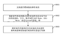
- FIG. 6 is a schematic flowchart of a method for managing a state machine of a wireless communication module by a main thread according to another embodiment of the present invention.
- the method for managing a state machine of a wireless communication module by the main thread includes:
- the wireless communication module receives an event message.
- the wireless communication module is specifically a wireless WIFI communication module.
- the wireless WIFI communication module supports Wi-Fi technology for household appliances.
- Household appliances such as air conditioners, refrigerators, and water heaters.
- an Asymmetric Digital Subscriber Line (ADSL), a cell broadband, or the like in a user's home can connect to a wireless communication module by using a home Wi-Fi technology to implement wireless access of the mobile terminal.
- the user can also interconnect the home appliance with the corresponding cloud server by using the wireless communication module to implement resource sharing between the home appliance and the cloud server.
- the wireless communication module in current home appliances is typically used as a receiving end, i.e., relies on another network providing device (e.g., a wired network) to provide a network connection to the home appliance.
- another network providing device e.g., a wired network
- the user may want to use the wireless communication module to increase the range covered by the network signal; or, may also want to enable the wireless communication module to convert the wired network into a wireless network at the same time; or, may also want to make the wireless communication module as a wireless base station (AP) ) to connect the electronic devices to each other.
- the wireless communication module in the home appliance of the related art can usually only provide one of the network forms or functions.
- the event message includes an application event message and a WIFI callback event message
- the wireless communication module receives the event message, including: the application event message queue receives the application event message generated by the service logic thread; and the WIFI event callback submodule receives the WIFI callback event message. After receiving the WIFI callback event message, the WIFI callback event message is added to the application event message queue.
- the application event message is generated by the main thread in the wireless communication module by the application event callback submodule controlling the business logic thread, and the WIFI callback event message is generated by the application.
- the application event message may be an actively generated event for the upper layer of the wireless communication module. For example, if the wireless communication module cancels the AP mode, an application event message of AF_EVT_AP_STOP is generated.
- the WIFI callback event message may be an event of the WIFI bottom feedback of the wireless communication module. For example, if the AP mode of the wireless communication module is successfully enabled, a WIFI callback event message of AF_EVT_AP_STARTED_SUCCESS is generated.
- the wireless communication module before receiving the event message, further includes: configuring a state transition mechanism of the wireless communication module.
- S602 Distribute the event message to the corresponding state machine according to the mode attribute of the event message, where the mode attribute is any one of AP-Mode, STA-Mode, or System.
- the state machine event distribution processing sub-module distributes the event message to the corresponding state machine according to the mode attribute of the event message, wherein the mode attribute is any one of AP-Mode, STA-Mode, or System.
- the wireless communication module supports an access point (AP) working mode AP-Mode, and the AP-Mode application is wireless.
- the wireless communication module can also support the workstation mode STA-Mode, or can be understood as a workstation in a grid, that is, the client.
- the WIFI chip of a wireless communication module provides the STA-Mode function
- the wireless communication module can be connected to another network.
- the AP-Mode is provided for connection to the mobile terminal, and the STA-Mode is used to provide data uplink services of the network.
- the system network state of the system in which the wireless communication module is located that is, the network connection state of the wireless communication module in the system and the network user may be described by the system state attribute, and the system state machine performs switching management between the system states.
- the state machine includes an AP-Mode state machine, a STA-Mode state machine, and a System state machine, a mode attribute AP-Mode corresponding to an AP-Mode state machine, a mode attribute STA-Mode corresponding to an STA-Mode state machine, and a mode attribute System. Corresponds to the System state machine.
- S603 Control the state of the wireless communication module to switch according to the event message and the state transition mechanism of the corresponding state machine.
- the state of the wireless communication module includes three states: an established AP, an AP running, and an idle state in the AP-Mode state machine, and three connections, a connected state, and an idle state in the STA-Mode state machine; The network in the machine is not established, the network has been established, and the three states are initialized.
- the state of the wireless communication module is controlled to be switched according to the event message and the state transition mechanism of the corresponding state machine, including: if the mode attribute of the event message is AP-Mode, the AP-Mode state machine is based on the event message and the AP- The state transition mechanism of the mode state machine controls the state of the wireless communication module to switch between establishing the AP, the AP running, and the idle state; if the mode attribute of the event message is STA-Mode, the STA-Mode state machine is The event message and the state transition mechanism of the STA-Mode state machine control the state of the wireless communication module to switch between three states: connected, connected, and idle; if the mode attribute of the event message is System, the System state machine is based on the event The message and state transition mechanism of the System state machine controls the state of the wireless communication module to switch between three states: network not established, network established, and initialized.
- the event message is distributed to the corresponding state machine according to the mode attribute of the event message, where the mode attribute is any one of AP-Mode, STA-Mode, or System, and according to the event message and the corresponding
- the state transition mechanism of the state machine controls the state of the wireless communication module to switch, and can realize the cooperative operation of the three state machines in the wireless communication module, thereby effectively improving the state management effect of the wireless communication module.
- FIG. 7 is a schematic flowchart of a method for managing a state machine of a wireless communication module by a main thread according to another embodiment of the present invention.
- the method for managing a state machine of a wireless communication module by the main thread includes:
- S701 Configure a state transition mechanism of the wireless communication module.
- the wireless communication module is specifically a wireless WIFI communication module.
- the wireless WIFI communication module supports Wi-Fi technology for household appliances.
- the state machine event distribution processing sub-module superimposes the state attributes of the AP-Mode state machine, the STA-Mode state machine, and the System state machine to configure a state transition mechanism of the wireless communication module.
- the state attribute of the state machine is used to identify the state of the wireless communication module.
- the built-in program in the wireless communication module can call the configured state attribute, so that the wireless communication module can switch between different states, and realize the cooperative operation of the three state machines in the wireless communication module.
- the application event message queue receives an application event message generated by the business logic thread.
- the application event message is generated by the main thread in the wireless communication module by the application event callback submodule controlling the business logic thread.
- the application event message may be an actively generated event for the upper layer of the wireless communication module. For example, if the wireless communication module cancels the AP mode, an application event message of AF_EVT_AP_STOP is generated.
- the WIFI event callback submodule receives the WIFI callback event message, and after receiving the WIFI callback event message, adds the WIFI callback event message to the application event message queue.
- the WIFI callback event message may be an event of the WIFI bottom feedback of the wireless communication module. For example, if the AP mode of the wireless communication module is successfully enabled, a WIFI callback event message of AF_EVT_AP_STARTED_SUCCESS is generated.
- S704 Read an application event message and a WIFI callback event message in the application event message queue.
- the main event thread in the wireless communication module reads the application event message and the WIFI callback event message in the application event message queue through the state machine event distribution processing submodule.
- S705 Distribute the event message to the corresponding state machine according to the mode attribute of the event message, where the mode attribute is any one of AP-Mode, STA-Mode, or System.
- the state machine event distribution processing sub-module distributes the event message to the corresponding state machine according to the mode attribute of the event message, wherein the mode attribute is any one of AP-Mode, STA-Mode, or System.
- the wireless communication module supports an access point (AP) working mode AP-Mode.
- the AP-Mode application is added to the wireless local area network member device (ie, the client), that is, the network is downlink, and the wireless local area network WLAN is established in a wireless manner, which is equivalent to the WLAN.
- Central equipment The wireless communication module can also support the workstation mode STA-Mode, or can be understood as a workstation in a grid, that is, the client.
- the WIFI chip of a wireless communication module provides the STA-Mode function
- the wireless communication module can be connected to another network.
- the AP-Mode is provided for connection to the mobile terminal, and the STA-Mode is used to provide data uplink services of the network.
- the system network state of the system in which the wireless communication module is located that is, the network connection state of the wireless communication module in the system and the network user may be described by the system state attribute, and the system state machine performs switching management between the system states.
- the state machine includes an AP-Mode state machine, a STA-Mode state machine, and a System state machine, a mode attribute AP-Mode corresponding to an AP-Mode state machine, a mode attribute STA-Mode corresponding to an STA-Mode state machine, and a mode attribute System. Corresponds to the System state machine.
- the logic of the code structure can be enhanced in the implementation of the underlying hardware of the wireless communication module, the complexity of the code development is reduced, and the function extension of the hardware system of the wireless communication module is facilitated.
- S706 Control switching the state of the wireless communication module according to the event message and the state transition mechanism.
- FIG. 8 it is a schematic diagram of state switching of a wireless communication module according to an embodiment of the present invention, which includes: an AP-Mode state machine 81, an STA-Mode state machine 82, a System state machine 83, and a state machine event distribution process.
- Sub-module 84 application event message queue 85, AP-Mode state machine state switching flow 86, STA-Mode state machine state switching flow 87, and System state machine state switching flow 88.
- the state of the wireless communication module can be controlled to switch according to the content of the event message and the state transition mechanism of the corresponding state machine.
- an AF_EVT_AP_STOP application event message is generated, and the content of the AF_EVT_AP_STOP application event message is a cancel AP mode, when the wireless communication module is in an AP running state, and the wireless communication is performed.
- the AP-Mode state machine controls the wireless communication module to switch from the state in which the AP is running to the idle state.
- the built-in program in the wireless communication module can invoke the configured state attribute, so that the wireless communication module can switch between different states, according to the mode according to the event message.
- the attribute distributes the event message to the corresponding state machine, wherein the mode attribute is any one of AP-Mode, STA-Mode, or System, and controls the wireless communication module according to the event message and the state transition mechanism of the corresponding state machine.
- the state is switched, and the cooperative operation of the three state machines in the wireless communication module can be realized, thereby effectively improving the state management effect of the wireless communication module.
- the logic of the code structure can be enhanced in the implementation of the underlying hardware of the wireless communication module, the complexity of the code development is reduced, and the function extension of the hardware system of the wireless communication module is facilitated.
- FIG. 9 is a schematic structural diagram of a cloud access system based on a wireless communication module 91 according to another embodiment of the present invention.
- the cloud access system 90 based on the wireless communication module 91 includes a wireless communication module 91 and communicates with each other through a wireless communication module 91.
- the cloud server 92 and the home appliance 93 wherein the wireless communication module 91 includes: a serial port data transceiving thread for communicating with the home appliance 93; a network data transceiving thread for communicating with the cloud server 92; a business logic thread, It is used for message exchange with the serial data receiving and sending thread and the network data sending and receiving thread to control the serial port data sending and receiving thread and the network data sending and receiving thread to send and receive messages; and the main thread, the main thread is used for serial port data sending and receiving thread, network data receiving and sending The thread and the business logic thread control; the application event callback submodule, the main thread controls the business logic thread by applying the event callback submodule; and the application event message queue is used for receiving the event message and being read by the main thread, wherein the event message Including application event messages and WIFI callback event messages; a state event distribution processing sub-module, configured to distribute the event message to a corresponding state machine according to a mode attribute of the event message, where the mode attribute is AP-Mode
- the cloud server 92 is based on resource sharing to reduce the cost and improve the efficiency of the flexible expansion of the IT infrastructure platform.
- the construction of the cloud server 92 is intended to provide services to a large number of users on demand.
- the cloud server 92 carries a large number of important service systems and data, and different home appliances 93 need to access the cloud server 92 to provide related services to users. Therefore, there are many requirements and challenges for the cloud server 92 to access.
- the cloud access system based on the wireless communication module 91 includes a wireless communication module 91.
- the implementation of the wireless communication module 91 is, for example, the embodiment of FIG. 5, and details are not described herein again.
- the cloud access system based on the wireless communication module 91 further includes a cloud server 92 and a home appliance 93 that communicate with each other through the wireless communication module 91.
- the cloud server 92 is a computing service that is simple, efficient, secure, and flexible in processing capability.
- the cloud server 92 is used to provide various types of Internet users with services that provide comprehensive business capabilities.
- the cloud server 92 is, for example, Midea Cloud, Jingdong Cloud, Facebook Cloud, or Xiaomi Cloud.
- the cloud server 92 has the functions of intelligent cloud access, intelligent cloud storage, and intelligent information push.
- the cloud server 92 can push the resource to the home appliance 93, and the user can perform the home appliance 93 through the application of the home appliance 93 in the mobile terminal. control.
- microwave ovens in the United States has newly developed cooking recipe resources.
- Microwave oven manufacturers store the newly developed cooking recipe resources in the cloud cloud of smart cloud storage.
- users use the wireless communication module 91 to interconnect the US microwave oven with the beautiful cloud.
- Midea Cloud will push the newly developed cooking recipe resources to the US microwave oven, so that users can control the beautiful microwave oven to implement the newly developed cooking recipe resources through the application of the microwave oven in the mobile terminal.
- Household appliances 93 refer to various electrical and electronic appliances used in homes and the like.
- the household appliance 93 is, for example, a television set, a refrigerator, or an air conditioner.
- more and more household appliances 93 can realize intelligent operation, and the user can install the application program of the home appliance 93 in the mobile terminal, and control the home appliance 93 through the application program.
- the user can also interconnect the home appliance 93 with the corresponding cloud server 92 by using the wireless communication module 91.
- the user may access the home appliance 93 that needs to obtain the service system and data in the cloud server 92 to access the corresponding cloud server 92 through the wireless communication module 91 to implement sharing of resources in the cloud server 92.
- the home appliance 93 that needs to acquire the business system and data in the cloud server 92 is a US air conditioner.
- the US air conditioner needs to share the protocol matching resources from the US cloud server 92. Therefore, the US air conditioner is passed through the wireless communication mode.
- Block 91 accesses the beautiful cloud to realize the sharing of the beautiful air conditioner with the beautiful cloud resources, or the beautiful air conditioner can be connected to the millet cloud through the wireless communication module 91 to realize the sharing of the beautiful air conditioner and the millet cloud resources. .
- the service logic thread exchanges messages with the serial port data sending and receiving thread and the network data sending and receiving thread, and controls the messages sent and received by the serial port data sending and receiving thread and the network data sending and receiving thread, and the main thread sends and receives threads and network data to the serial port.
- the sending and receiving threads and the business logic thread control can realize the cooperative operation of multiple threads, effectively improve the thread scheduling effect in the cloud server access process, and facilitate the function expansion of the late wireless communication module hardware system.
- Distributing the event message to the corresponding state machine according to the mode attribute of the event message, wherein the mode attribute is any one of AP-Mode, STA-Mode, or System and is converted according to the event message and the state of the corresponding state machine.
- the mechanism controls the state of the wireless communication module to switch, and can realize the cooperative operation of the three state machines in the wireless communication module of the home appliance, thereby effectively improving the state management effect of the wireless communication module.
- each functional unit in each embodiment of the present invention may be integrated into one processing module, or each unit may exist physically separately, or two or more units may be integrated into one module.
- the above integrated modules can be implemented in the form of hardware or in the form of software functional modules.
- the integrated modules, if implemented in the form of software functional modules and sold or used as stand-alone products, may also be stored in a computer readable storage medium.
- the above mentioned storage medium may be a read only memory, a magnetic disk or an optical disk or the like.
Landscapes
- Engineering & Computer Science (AREA)
- Computer Networks & Wireless Communication (AREA)
- Signal Processing (AREA)
- Automation & Control Theory (AREA)
- Computing Systems (AREA)
- Computer Security & Cryptography (AREA)
- Health & Medical Sciences (AREA)
- General Health & Medical Sciences (AREA)
- Medical Informatics (AREA)
- Mobile Radio Communication Systems (AREA)
- Computer And Data Communications (AREA)
Abstract
Description
Claims (27)
- 一种基于无线通信模块的云接入方法,所述无线通信模块用于家用电器,其特征在于,包括以下步骤:无线通信模块接收云服务器发送的第一类型报文,并获取所述云服务器的类型信息,其中,所述无线通信模块与多个云服务器相连接;所述无线通信模块根据所述云服务器的类型信息调用对应的转换协议;以及所述无线通信模块根据所述转换协议将所述第一类型报文转换为第二类型报文,并将所述第二类型报文发送至对应的家用电器。
- 如权利要求1所述的基于无线通信模块的云接入方法,其特征在于,所述获取所述云服务器的类型信息具体包括:所述无线通信模块获取与所述云服务器相连接的Socket连接信息;以及所述无线通信模块根据所述Socket连接信息确定所述类型信息。
- 如权利要求1所述的基于无线通信模块的云接入方法,其特征在于,还包括:无线通信模块接收家用电器发送的第二类型报文,并获取所述第二类型报文对应的目的地址,以及根据所述目标地址确定对应云服务器的类型信息;所述无线通信模块根据所述云服务器的类型信息调用对应的转换协议;以及所述无线通信模块根据所述转换协议将所述第二类型报文转换为第一类型报文,并将所述第一类型报文发送至对应的云服务器。
- 如权利要求1-3任一项所述的基于无线通信模块的云接入方法,其特征在于,所述无线通信模块中包括:串口数据收发线程,用于与所述家用电器进行通信;网络数据收发线程,用于与所述云服务器进行通信;业务逻辑线程,用于与所述串口数据收发线程、所述网络数据收发线程进行消息交换,以对所述串口数据收发线程和所述网络数据收发线程收发的消息进行控制;以及主线程,所述主线程用于对所述串口数据收发线程、网络数据收发线程和业务逻辑线程进行控制。
- 如权利要求4所述的基于无线通信模块的云接入方法,其特征在于,所述无线通信模块中还包括:第一串口接收数据消息队列,所述第一串口接收数据消息队列用于接收所述串口数据收发线程发送的消息,并将所述消息提供给所述业务逻辑线程进行读取;第一串口数据接收缓存,所述第一串口数据接收缓存接收并缓存所述串口数据收发线程发送的数据,并将所述数据提供给所述业务逻辑线程进行读取;第二串口接收数据消息队列,所述第二串口接收数据消息队列用于接收所述业务逻辑线程发送的消息,并将所述消息提供给所述串口数据收发线程进行读取;以及第二串口数据接收缓存,所述第二串口数据接收缓存接收并缓存所述业务逻辑线程发送的数据,并将所述数据提供给所述串口数据收发线程进行读取。
- 如权利要求5所述的基于无线通信模块的云接入方法,其特征在于,在所述第一串口数据接收缓存和第二串口数据接收缓存的数据被读取之后,将所述数据在所述第一串口数据接收缓存和第二串口数据接收缓存中删除。
- 如权利要求4所述的基于无线通信模块的云接入方法,其特征在于,所述无线通信模块中还包括:第一网络接收数据消息队列,所述第一网络接收数据消息队列用于接收所述网络数据收发线程发送的消息,并将所述消息提供给所述业务逻辑线程进行读取;第一网络数据接收缓存,所述第一网络数据接收缓存接收并缓存所述网络数据收发线程发送的数据,并将所述数据提供给所述业务逻辑线程进行读取;第二网络接收数据消息队列,所述第二网络接收数据消息队列用于接收所述业务逻辑线程发送的消息,并将所述消息提供给所述网络数据收发线程进行读取;以及第二网络数据接收缓存,所述第二网络数据接收缓存接收并缓存所述业务逻辑线程发送的数据,并将所述数据提供给所述网络数据收发线程进行读取。
- 如权利要求7所述的基于无线通信模块的云接入方法,其特征在于,在所述第一网络数据接收缓存和第二网络数据接收缓存的数据被读取之后,将所述数据在所述第一网络数据接收缓存和第二网络数据接收缓存中删除。
- 如权利要求4所述的基于无线通信模块的云接入方法,其特征在于,所述无线通信模块中还包括:应用事件回调子模块,所述主线程通过所述应用事件回调子模块控制所述业务逻辑线程;以及应用事件消息队列,用于接收所述业务逻辑线程生成的应用事件消息,并供所述主线程读取。
- 如权利要求4所述的基于无线通信模块的云接入方法,其特征在于,所述无线通信模块中还包括:WIFI事件回调子模块,用于接收WIFI回调事件,并在接收到所述WIFI回调事件之后,将所述WIFI回调事件添加至所述应用事件消息队列。
- 如权利要求10所述的基于无线通信模块的云接入方法,其特征在于,所述WIFI回调事件由应用程序产生。
- 如权利要求1所述的基于无线通信模块的云接入方法,其特征在于,所述主线程用于对所述无线通信模块的状态机进行管理。
- 如权利要求12所述的基于无线通信模块的云接入方法,其特征在于,所述主线程用于对所述无线通信模块的状态机进行管理,具体包括:所述无线通信模块接收事件消息;根据所述事件消息的模式属性将所述事件消息分发至对应的状态机,其中,所述模式属性为AP-Mode、STA-Mode,或者System中的任一种;根据所述事件消息和所述对应的状态机的状态转换机制控制所述无线通信模块的状态进行切换。
- 如权利要求13所述的基于无线通信模块的云接入方法,其特征在于,所述无线通信模块接收事件消息之前,还包括:配置所述无线通信模块的状态转换机制。
- 如权利要求14所述的基于无线通信模块的云接入方法,其特征在于,所述状态机包括AP-Mode状态机、STA-Mode状态机,以及System状态机,所述模式属性AP-Mode对应AP-Mode状态机、所述模式属性STA-Mode对应STA-Mode状态机,以及所述模式属性System对应System状态机。
- 如权利要求14所述的基于无线通信模块的云接入方法,其特征在于,所述配置所述无线通信模块的状态转换机制,包括:将所述AP-Mode状态机、所述STA-Mode状态机,以及所述System状态机的状态属性叠加,以配置所述无线通信模块的状态转换机制。
- 如权利要求13所述的基于无线通信模块的云接入方法,其特征在于,所述无线通信模块的状态包括AP-Mode状态机中的建立AP中、AP运行中、以及空闲三种状态,STA-Mode状态机中的连接中、已连接、以及空闲三种状态;System状态机中的网络未建立、网络已建立、以及初始化三种状态。
- 如权利要求17所述的基于无线通信模块的云接入方法,其特征在于,所述根据所述事件消息和所述对应的状态机的状态转换机制控制所述无线通信模块的状态进行切换,包括:如果所述事件消息的模式属性为AP-Mode,则AP-Mode状态机根据所述事件消息和所述AP-Mode状态机的状态转换机制控制所述无线通信模块的状态在建立AP中、AP运行中、以及空闲三种状态之间进行切换;如果所述事件消息的模式属性为STA-Mode,则STA-Mode状态机根据所述事件消息和所述STA-Mode状态机的状态转换机制控制所述无线通信模块的状态在连接中、已连接、以及 空闲三种状态之间进行切换;如果所述事件消息的模式属性为System,则System状态机根据所述事件消息和所述System状态机的状态转换机制控制所述无线通信模块的状态在网络未建立、网络已建立、以及初始化三种状态之间进行切换。
- 如权利要求13所述的基于无线通信模块的云接入方法,其特征在于,所述事件消息包括应用事件消息和WIFI回调事件消息,所述无线通信模块接收事件消息,包括:所述应用事件消息队列接收所述业务逻辑线程生成的应用事件消息;所述WIFI事件回调子模块接收所述WIFI回调事件消息,并在接收到所述WIFI回调事件消息之后,将所述WIFI回调事件消息添加至所述应用事件消息队列。
- 如权利要求19所述的基于无线通信模块的云接入方法,其特征在于,还包括:读取所述应用事件消息队列中的所述应用事件消息和所述WIFI回调事件消息。
- 一种基于无线通信模块的云接入系统,所述无线通信模块用于家用电器,其特征在于,包括无线通信模块、通过所述无线通信模块相互通信的云服务器和家用电器,其中,所述无线通信模块中包括:串口数据收发线程,用于与所述家用电器进行通信;网络数据收发线程,用于与所述云服务器进行通信;业务逻辑线程,用于与所述串口数据收发线程、所述网络数据收发线程进行消息交换,以对所述串口数据收发线程和所述网络数据收发线程收发的消息进行控制;主线程,所述主线程用于对所述串口数据收发线程、网络数据收发线程和业务逻辑线程进行控制;应用事件回调子模块,所述主线程通过所述应用事件回调子模块控制所述业务逻辑线程;以及应用事件消息队列,用于接收事件消息,并供所述主线程读取,其中,所述事件消息包括应用事件消息和WIFI回调事件消息;状态机事件分发处理子模块,用于根据所述事件消息的模式属性将所述事件消息分发至对应的状态机,其中,所述模式属性为AP-Mode、STA-Mode,或者System中的任一种,读取所述应用事件消息队列中的所述应用事件消息和WIFI回调事件消息,配置所述无线通信模块的状态转换机制;状态机,用于根据所述事件消息和状态转换机制控制所述无线通信模块的状态进行切换。
- 如权利要求21所述的基于无线通信模块的云接入系统,其特征在于,所述无线通信模块中还包括:第一串口接收数据消息队列,所述第一串口接收数据消息队列用于接收所述串口数据收发线程发送的消息,并将所述消息提供给所述业务逻辑线程进行读取;第一串口数据接收缓存,所述第一串口数据接收缓存接收并缓存所述串口数据收发线程发送的数据,并将所述数据提供给所述业务逻辑线程进行读取;第二串口接收数据消息队列,所述第二串口接收数据消息队列用于接收所述业务逻辑线程发送的消息,并将所述消息提供给所述串口数据收发线程进行读取;以及第二串口数据接收缓存,所述第二串口数据接收缓存接收并缓存所述业务逻辑线程发送的数据,并将所述数据提供给所述串口数据收发线程进行读取。
- 如权利要求22所述的基于无线通信模块的云接入系统,其特征在于,在所述第一串口数据接收缓存和第二串口数据接收缓存的数据被读取之后,将所述数据在所述第一串口数据接收缓存和第二串口数据接收缓存中删除。
- 如权利要求21所述的基于无线通信模块的云接入系统,其特征在于,所述无线通信模块中还包括:第一网络接收数据消息队列,所述第一网络接收数据消息队列用于接收所述网络数据收发线程发送的消息,并将所述消息提供给所述业务逻辑线程进行读取;第一网络数据接收缓存,所述第一网络数据接收缓存接收并缓存所述网络数据收发线程发送的数据,并将所述数据提供给所述业务逻辑线程进行读取;第二网络接收数据消息队列,所述第二网络接收数据消息队列用于接收所述业务逻辑线程发送的消息,并将所述消息提供给所述网络数据收发线程进行读取;以及第二网络数据接收缓存,所述第二网络数据接收缓存接收并缓存所述业务逻辑线程发送的数据,并将所述数据提供给所述网络数据收发线程进行读取。
- 如权利要求24所述的基于无线通信模块的云接入系统,其特征在于,在所述第一网络数据接收缓存和第二网络数据接收缓存的数据被读取之后,将所述数据在所述第一网络数据接收缓存和第二网络数据接收缓存中删除。
- 如权利要求21所述的基于无线通信模块的云接入系统,其特征在于,所述无线通信模块中还包括:WIFI事件回调子模块,用于接收WIFI回调事件,并在接收到所述WIFI回调事件之后,将所述WIFI回调事件添加至所述应用事件消息队列。
- 如权利要求26所述的基于无线通信模块的云接入系统,其特征在于,所述WIFI回调事件由应用程序产生。
Priority Applications (1)
| Application Number | Priority Date | Filing Date | Title |
|---|---|---|---|
| US16/008,052 US20180367647A1 (en) | 2015-12-14 | 2018-06-14 | Wireless communication module based cloud access method and system |
Applications Claiming Priority (2)
| Application Number | Priority Date | Filing Date | Title |
|---|---|---|---|
| CN201510932085.1A CN105791377B (zh) | 2015-12-14 | 2015-12-14 | 基于无线通信模块的云接入系统和方法 |
| CN201510932085.1 | 2015-12-14 |
Related Child Applications (1)
| Application Number | Title | Priority Date | Filing Date |
|---|---|---|---|
| US16/008,052 Continuation US20180367647A1 (en) | 2015-12-14 | 2018-06-14 | Wireless communication module based cloud access method and system |
Publications (1)
| Publication Number | Publication Date |
|---|---|
| WO2017101079A1 true WO2017101079A1 (zh) | 2017-06-22 |
Family
ID=56389945
Family Applications (1)
| Application Number | Title | Priority Date | Filing Date |
|---|---|---|---|
| PCT/CN2015/097741 Ceased WO2017101079A1 (zh) | 2015-12-14 | 2015-12-17 | 一种基于无线通信模块的云接入方法和系统 |
Country Status (3)
| Country | Link |
|---|---|
| US (1) | US20180367647A1 (zh) |
| CN (1) | CN105791377B (zh) |
| WO (1) | WO2017101079A1 (zh) |
Families Citing this family (3)
| Publication number | Priority date | Publication date | Assignee | Title |
|---|---|---|---|---|
| CN106808608A (zh) * | 2016-12-31 | 2017-06-09 | 重庆安特管业有限公司 | 一种智能切割机 |
| CN107517146A (zh) * | 2017-08-31 | 2017-12-26 | 广东美的制冷设备有限公司 | 身份类型标识的配置系统和配置方法及移动终端 |
| CN114116153A (zh) * | 2020-08-31 | 2022-03-01 | 华为技术有限公司 | 基于代理服务的设备调用方法、电子设备及可读存储介质 |
Citations (4)
| Publication number | Priority date | Publication date | Assignee | Title |
|---|---|---|---|---|
| US20140156028A1 (en) * | 2012-11-30 | 2014-06-05 | General Electric Company | Cloud-based bi-directional messaging system for home appliance control |
| CN103916464A (zh) * | 2014-03-19 | 2014-07-09 | 广东志高空调有限公司 | 一种基于Wi-Fi通信方式的双模云空调系统 |
| CN104243616A (zh) * | 2014-10-10 | 2014-12-24 | 广东志高空调有限公司 | 一种基于Wi-Fi通信的云空调系统 |
| CN204404559U (zh) * | 2015-01-18 | 2015-06-17 | 李俊楠 | 一种基于Wi-Fi通信的云热水器系统 |
Family Cites Families (3)
| Publication number | Priority date | Publication date | Assignee | Title |
|---|---|---|---|---|
| CN102981440B (zh) * | 2012-11-02 | 2014-10-29 | 武汉理工大学 | 基于SaaS的智能设备监控管理系统 |
| US9444899B2 (en) * | 2012-12-26 | 2016-09-13 | Microsoft Technology Licensing, Llc | Use of internet information services logging to collect user information in an asynchronous manner |
| CN203965907U (zh) * | 2014-06-24 | 2014-11-26 | 北车大连电力牵引研发中心有限公司 | 轨道交通通信系统 |
-
2015
- 2015-12-14 CN CN201510932085.1A patent/CN105791377B/zh active Active
- 2015-12-17 WO PCT/CN2015/097741 patent/WO2017101079A1/zh not_active Ceased
-
2018
- 2018-06-14 US US16/008,052 patent/US20180367647A1/en not_active Abandoned
Patent Citations (4)
| Publication number | Priority date | Publication date | Assignee | Title |
|---|---|---|---|---|
| US20140156028A1 (en) * | 2012-11-30 | 2014-06-05 | General Electric Company | Cloud-based bi-directional messaging system for home appliance control |
| CN103916464A (zh) * | 2014-03-19 | 2014-07-09 | 广东志高空调有限公司 | 一种基于Wi-Fi通信方式的双模云空调系统 |
| CN104243616A (zh) * | 2014-10-10 | 2014-12-24 | 广东志高空调有限公司 | 一种基于Wi-Fi通信的云空调系统 |
| CN204404559U (zh) * | 2015-01-18 | 2015-06-17 | 李俊楠 | 一种基于Wi-Fi通信的云热水器系统 |
Also Published As
| Publication number | Publication date |
|---|---|
| CN105791377A (zh) | 2016-07-20 |
| US20180367647A1 (en) | 2018-12-20 |
| CN105791377B (zh) | 2017-05-24 |
Similar Documents
| Publication | Publication Date | Title |
|---|---|---|
| CN111200878B (zh) | 信息传输方法及其装置 | |
| US11528239B2 (en) | Time-sensitive networking communication method and apparatus for configuring virtual switching node | |
| US11128486B2 (en) | Smart refrigerator-based networking and control method and system, and smart refrigerator | |
| CN107426797B (zh) | 用于接入网侧的切片管控系统和方法 | |
| WO2020103834A1 (zh) | 时延敏感网络通信方法及其装置 | |
| CN105871992B (zh) | 基于无线通信模块的云接入系统和方法 | |
| CN110740149B (zh) | 通信方法和装置 | |
| TW201813354A (zh) | 無線通訊系統的資源分配方法及其設備和系統 | |
| WO2015051704A1 (zh) | 移动终端多apn网络并发系统及其联网方法 | |
| CN105871991B (zh) | 基于无线通信模块的云接入系统和方法 | |
| CN104410982B (zh) | 一种无线异构网络中终端聚合与重构方法 | |
| CN103856374A (zh) | 一种数据传输方法、终端及家庭互联系统 | |
| WO2020034861A1 (zh) | 通信方法和装置 | |
| CN105871993B (zh) | 基于无线通信模块的云接入方法和系统 | |
| WO2020164522A1 (zh) | 数据传输控制方法及相关产品 | |
| WO2017101079A1 (zh) | 一种基于无线通信模块的云接入方法和系统 | |
| WO2011137621A1 (zh) | 管理分布式基站的方法和装置 | |
| CN105578505B (zh) | 无线通信模块的状态管理方法和无线通信模块 | |
| WO2024067062A1 (zh) | 数据传输方法和相关产品 | |
| CN105429900B (zh) | 一种带宽提速的方法、装置及系统 | |
| WO2012151803A1 (zh) | 一种虚拟终端系统及实现方法 | |
| CN105245376A (zh) | 基于sdn的住宅小区网络控制系统 | |
| CN114500133A (zh) | 一种家电设备及家电设备的入网方法 | |
| CN112994996B (zh) | 家庭网络共享方法、mec服务器、计算机设备及介质 | |
| CN113890834B (zh) | MEC系统与DPoH系统的通信方法及装置 |
Legal Events
| Date | Code | Title | Description |
|---|---|---|---|
| 121 | Ep: the epo has been informed by wipo that ep was designated in this application |
Ref document number: 15910551 Country of ref document: EP Kind code of ref document: A1 |
|
| NENP | Non-entry into the national phase |
Ref country code: DE |
|
| 122 | Ep: pct application non-entry in european phase |
Ref document number: 15910551 Country of ref document: EP Kind code of ref document: A1 |
|
| 32PN | Ep: public notification in the ep bulletin as address of the adressee cannot be established |
Free format text: NOTING OF LOSS OF RIGHTS PURSUANT TO RULE 112(1) EPC (EPO FORM 1205A DATED 03/12/2018) |
|
| 122 | Ep: pct application non-entry in european phase |
Ref document number: 15910551 Country of ref document: EP Kind code of ref document: A1 |