WO2017077677A1 - Base station, terminal and communication method - Google Patents
Base station, terminal and communication method Download PDFInfo
- Publication number
- WO2017077677A1 WO2017077677A1 PCT/JP2016/004130 JP2016004130W WO2017077677A1 WO 2017077677 A1 WO2017077677 A1 WO 2017077677A1 JP 2016004130 W JP2016004130 W JP 2016004130W WO 2017077677 A1 WO2017077677 A1 WO 2017077677A1
- Authority
- WO
- WIPO (PCT)
- Prior art keywords
- prb
- prb set
- resource
- pucch
- mpdcch
- Prior art date
Links
- 238000000034 method Methods 0.000 title claims description 30
- 238000004891 communication Methods 0.000 title claims description 12
- 101000741965 Homo sapiens Inactive tyrosine-protein kinase PRAG1 Proteins 0.000 claims abstract description 55
- 102100038659 Inactive tyrosine-protein kinase PRAG1 Human genes 0.000 claims abstract description 55
- 238000000926 separation method Methods 0.000 claims abstract description 14
- 238000013468 resource allocation Methods 0.000 claims description 16
- 230000002776 aggregation Effects 0.000 description 61
- 238000004220 aggregation Methods 0.000 description 61
- 230000005540 biological transmission Effects 0.000 description 29
- 238000010586 diagram Methods 0.000 description 20
- 238000012937 correction Methods 0.000 description 17
- 230000011664 signaling Effects 0.000 description 12
- 238000001514 detection method Methods 0.000 description 8
- 238000013507 mapping Methods 0.000 description 6
- 238000012545 processing Methods 0.000 description 6
- 101150071746 Pbsn gene Proteins 0.000 description 4
- 238000006243 chemical reaction Methods 0.000 description 4
- 238000005516 engineering process Methods 0.000 description 4
- 101150055297 SET1 gene Proteins 0.000 description 3
- 238000007726 management method Methods 0.000 description 3
- 229940102240 option 2 Drugs 0.000 description 3
- 102100038353 Gremlin-2 Human genes 0.000 description 2
- 101001032860 Mus musculus Gremlin-2 Proteins 0.000 description 2
- 238000004590 computer program Methods 0.000 description 2
- 238000005520 cutting process Methods 0.000 description 2
- 230000000694 effects Effects 0.000 description 2
- 230000010354 integration Effects 0.000 description 2
- 238000004519 manufacturing process Methods 0.000 description 2
- 230000008569 process Effects 0.000 description 2
- 230000009467 reduction Effects 0.000 description 2
- YYJUXSGXHHPBTK-UHFFFAOYSA-N 2-chloro-3-(3-chloro-2-methylphenyl)propanenitrile Chemical compound CC1=C(Cl)C=CC=C1CC(Cl)C#N YYJUXSGXHHPBTK-UHFFFAOYSA-N 0.000 description 1
- 101001056707 Homo sapiens Proepiregulin Proteins 0.000 description 1
- 102100025498 Proepiregulin Human genes 0.000 description 1
- 230000001413 cellular effect Effects 0.000 description 1
- 230000008859 change Effects 0.000 description 1
- 239000013256 coordination polymer Substances 0.000 description 1
- 230000008021 deposition Effects 0.000 description 1
- 244000144972 livestock Species 0.000 description 1
- 238000010295 mobile communication Methods 0.000 description 1
- 230000004048 modification Effects 0.000 description 1
- 238000012986 modification Methods 0.000 description 1
- 239000004065 semiconductor Substances 0.000 description 1
Images


Classifications
-
- H—ELECTRICITY
- H04—ELECTRIC COMMUNICATION TECHNIQUE
- H04W—WIRELESS COMMUNICATION NETWORKS
- H04W72/00—Local resource management
- H04W72/20—Control channels or signalling for resource management
- H04W72/23—Control channels or signalling for resource management in the downlink direction of a wireless link, i.e. towards a terminal
-
- H—ELECTRICITY
- H04—ELECTRIC COMMUNICATION TECHNIQUE
- H04L—TRANSMISSION OF DIGITAL INFORMATION, e.g. TELEGRAPHIC COMMUNICATION
- H04L1/00—Arrangements for detecting or preventing errors in the information received
- H04L1/12—Arrangements for detecting or preventing errors in the information received by using return channel
- H04L1/16—Arrangements for detecting or preventing errors in the information received by using return channel in which the return channel carries supervisory signals, e.g. repetition request signals
-
- H—ELECTRICITY
- H04—ELECTRIC COMMUNICATION TECHNIQUE
- H04L—TRANSMISSION OF DIGITAL INFORMATION, e.g. TELEGRAPHIC COMMUNICATION
- H04L5/00—Arrangements affording multiple use of the transmission path
- H04L5/003—Arrangements for allocating sub-channels of the transmission path
- H04L5/0053—Allocation of signaling, i.e. of overhead other than pilot signals
- H04L5/0055—Physical resource allocation for ACK/NACK
-
- H—ELECTRICITY
- H04—ELECTRIC COMMUNICATION TECHNIQUE
- H04W—WIRELESS COMMUNICATION NETWORKS
- H04W72/00—Local resource management
- H04W72/04—Wireless resource allocation
-
- H—ELECTRICITY
- H04—ELECTRIC COMMUNICATION TECHNIQUE
- H04W—WIRELESS COMMUNICATION NETWORKS
- H04W72/00—Local resource management
- H04W72/12—Wireless traffic scheduling
-
- H—ELECTRICITY
- H04—ELECTRIC COMMUNICATION TECHNIQUE
- H04W—WIRELESS COMMUNICATION NETWORKS
- H04W88/00—Devices specially adapted for wireless communication networks, e.g. terminals, base stations or access point devices
- H04W88/08—Access point devices
-
- Y—GENERAL TAGGING OF NEW TECHNOLOGICAL DEVELOPMENTS; GENERAL TAGGING OF CROSS-SECTIONAL TECHNOLOGIES SPANNING OVER SEVERAL SECTIONS OF THE IPC; TECHNICAL SUBJECTS COVERED BY FORMER USPC CROSS-REFERENCE ART COLLECTIONS [XRACs] AND DIGESTS
- Y02—TECHNOLOGIES OR APPLICATIONS FOR MITIGATION OR ADAPTATION AGAINST CLIMATE CHANGE
- Y02D—CLIMATE CHANGE MITIGATION TECHNOLOGIES IN INFORMATION AND COMMUNICATION TECHNOLOGIES [ICT], I.E. INFORMATION AND COMMUNICATION TECHNOLOGIES AIMING AT THE REDUCTION OF THEIR OWN ENERGY USE
- Y02D30/00—Reducing energy consumption in communication networks
- Y02D30/70—Reducing energy consumption in communication networks in wireless communication networks
Definitions
- the present disclosure relates to a base station, a terminal, and a communication method.
- MTC Machine-Type Communications
- MTC terminal sometimes referred to as MTC terminal or MTC UE
- MTC terminal it is assumed that a terminal corresponding to MTC (sometimes referred to as MTC terminal or MTC UE) and a network are connected.
- MTC terminal sometimes referred to as MTC terminal or MTC UE
- MTC terminal it is expected that the traffic volume of each MTC terminal is not so large. Therefore, it is desired that the MTC terminal has low cost and low power consumption.
- Narrowband is defined to consist of continuous PRBs.
- MPDCCH Physical Downlink Control CHannel
- MPDCCH is arranged in the PDSCH area in Narrowband.
- MTC is considering a method of assigning MPDCCH to all 6PRB pairs included in Narrowband for coverage extension.
- EPDCCH there are 16 EREGs (Enhanced Resource Element Group) per 1 PRB pair, and if the number of EREGs per 1 ECCE (Enhanced CCE) is 4, the ECCE number of 6 PRB pair is 24 ECCE.
- ECCE is a unit for assigning EPDCCH
- EREG is a unit used for mapping ECCE to RE (Resource Element).
- PRB ⁇ ⁇ pair is a unit of resource, which is 1 subframe (time direction) ⁇ 12 subcarriers (frequency), and may be simply called PRB when showing only on the frequency axis.
- MPDCCH set for MTC terminals it is considered to arrange MPDCCH (4 PR PRB set) consisting of 4 PRB pairs or MPDCCH (2 PRB set) consisting of 2 PRB pairs in 6 PRB pairs.
- 1, 2, 4, 8, 16, and 24 have been studied as the aggregation level of MPDCCH.
- MTC terminals receive the downlink control signal MPDCCH, receive downlink data (PDSCH) specified by MPDCCH, and receive ACK / NACK signals as UL control signals. Send on a PUCCH.
- each MTC terminal uses an offset (called “N_pucch”) set for each PRBPRset in the same manner as EPDCCH in order to specify the PUCCH resource (PUCCH resource) for the MTC terminal. It is being considered.
- N_pucch an offset for “24ECCEs” in which one MPDCCH is placed in all 6PRB pairs in Narrowband.
- one aspect of the present disclosure provides a base station, a terminal, and a communication method that can efficiently specify a PUCCH resource when one MPDCCH is allocated to all 6PRB pairs in a narrowband.
- a base station is based on a signal allocation unit that allocates a downlink control signal including resource allocation information of PDSCH (Physical Downlink Shared Channel) to a downlink resource, and a downlink resource to which the downlink control signal is allocated.
- PDSCH Physical Downlink Shared Channel
- a downlink resource is composed of a plurality of PRB pairs, and each of the plurality of PRB pairs is assigned either the first PRB set or the second PRB set, and the specifying unit is When the downlink control signal is arranged across the first PRBPRset and the second PRB set, the offset value set in one of the first PRB set and the second PRB set is used.
- a terminal includes a receiving unit that receives a downlink control signal including PDSCH (Physical-Downlink-Shared-Channel) resource allocation information, and an ACK / PD for PDSCH based on the downlink resource to which the downlink control signal is allocated.
- PDSCH Physical-Downlink-Shared-Channel
- a specifying unit that identifies a PUCCH (Physical Uplink Control Channel) resource to which a NACK signal is allocated, and a signal allocation unit that allocates the ACK / NACK signal to the specified PUCCH resource, and the downlink resource includes a plurality of PRB pairs Each of the plurality of PRB sets is assigned either one of the first PRB set and the second PRB set, and the specifying unit has the downlink control signal arranged across the first PRB set and the second PRB set.
- the PUCCH resource is specified using the offset value set in either the first PRB set or the second PRB set.
- PUCCH resource conceptual diagram Diagram showing an example of MPDCCH placement method (Option 1) Diagram showing an example of MPDCCH placement method (Option 1) Diagram showing an example of MPDCCH placement method (Option 2) Diagram showing an example of MPDCCH placement method (Option 2)
- PUCCH resource conceptual diagram Diagram for explaining the problem of the third embodiment Diagram for explaining the problem of the third embodiment The figure which shows an example of the arrangement method of MPDCCH which concerns on the operation example 6 of Embodiment 3.
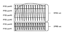
- FIG. Diagram showing an example of allocation of 4 PRB set related to variations Diagram showing an example of allocation of 2 PRB ⁇ ⁇ set related to variations
- N_pucch the offset (N_pucch) for specifying the PUCCH resource for the MTC terminal. It is possible to distinguish the PUCCH resource of the conventional terminal and the MTC terminal and to avoid the collision of the PUCCH resource. Further, when N_pucch is instructed for each repetition level, it is possible to avoid collision of PUCCH resources between MTC terminals having different repetition levels. Thereby, it is possible to solve the perspective problem that occurs when signals of terminals having different distances from the base station are multiplexed.
- N_pucch for a single MTC cannot avoid collision of PUCCH resources between multiple MTC terminals with the same repetition level.
- the ACK / NACK is determined from the arrangement of the DL control signal (MPDCCH) in which the DL assignment signal instructing transmission of the DL data signal is transmitted in the same manner as EPDCCH. It can be considered that the resource of PUCCH format 1a / 1b that transmits
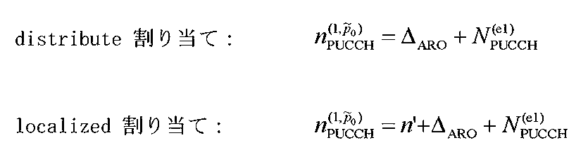
- EPDCCH-PRB-set q 0,1 offset N PUCCH for each, q (e1) (hereinafter, "N_pucch, q" described in abbreviated) is set, identified PUCCH resource from ECCE number Is done.
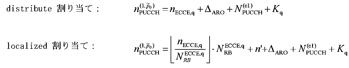
- N_pucch, q the resource (resource number) of PUCCH format 1a / 1b is specified by the following equation.
- n ECCE, q represents an offset based on the first ECCE number to which DCI (Downlink Control Information) is mapped in the q-th EPDCCH PRB set.
- ⁇ ARO represents an offset indicated by 2-bit ARO (ACK / NACK Resource Offset) included in DCI, and takes a value of ⁇ 2, ⁇ 1, 0, +2 in the case of FDD.
- N PUCCH, q (e1) is reported in the upper layer for each terminal.
- N RB ECCE, q represents the number of ECCEs per RB, and n ′ represents an offset based on the antenna port.
- FIG. 1 shows a conceptual diagram of the PUCCH resource described above.
- N PUCCH, 0 (e1) and N PUCCH, 1 (e1) set in each PRB set are arranged so that they do not overlap, and collision of PUCCH resources can be avoided.
- N PUCCH, 0 (e1) and N PUCCH, 1 (e1) can be set to close values, and the PUCCH resources corresponding to each PRB set can be overlapped to reduce the entire PUCCH resource.
- PUCCH resources can be specified in the same way as EPDCCH.
- the PUCCH resource can be specified for the MPDCCH arranged in the PRB set composed of 4PRB ⁇ pairs or 2PRB pairs by the same method as the EPDCCH described above.
- the 24DCCEs MPDCCH used in MTC is arranged in all REs that can be used for MPDCCH included in 6PRBpair in Narrowband.
- two options 1 and 2 that can be considered as an arrangement method of MPDCCH of 24ECCEs will be described.
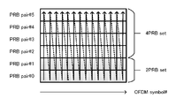
- Option 1 24ECCEs of MPDCCH are arranged with frequency first. Specifically, in Narrowband, the symbol string of MPDCCH is arranged from the OFDM symbol with the lower OFDM symbol number to the next OFDM symbol after being arranged from the lower frequency to the higher frequency by cutting the PRB pair. The PRB pair is cut vertically and arranged from the lowest to the highest frequency.
- 2A and 2B show an example of MPDCCH arrangement of Option ⁇ 1.
- 2PRB set is assigned to PRB pair # 0, # 1
- 4PRB set is assigned to PRB pair # 2 to # 5.
- the resource of 2PRB set (PRB pair # 0, # 1) and the resource of 4 PRB set (PRB pair # 2 to # 5) are not distinguished and all 24DCCEs MPDCCH can be used for MPDCCH. Is placed.
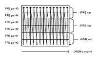
- 2PRB set is assigned to PRB pair # 2, # 3, and 4PRB set is assigned to PRB pair # 0, # 1, # 4, # 5.
- 2PRBPRset resources PRB pair # 2, # 3
- 4PRB set resources PRB pair # 0, # 1, # 4, # 5 are not distinguished in FIG. , 24ECCEs of MPDCCH are allocated to all REs that can be used for MPDCCH.
- MPECCH of 24ECCEs is arranged in advance of MPDCCH PRB set in Narrowband. Therefore, the arrangement order of MPDCCH is changed depending on which PRB pair the PRB set is assigned to.
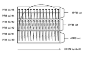
- 3A and 3B show an example of MPDCCH arrangement of Option-2, in which MPDCCH is arranged first from 4PRB set. Specifically, the MPDCCH is first placed in the RE in the 4 PRB set, and then placed in the RE in the 2 PRB set.
- the arrangement in 4PRB set and 2PRB ⁇ ⁇ set is preceded by frequency as in EPDCCH. That is, in the PRB pair in the PRB pair, the symbol string of MPDCCH is arranged from the OFDM part symbol having a low OFDM part number to the next OFDM part symbol after being vertically arranged in the PRB part pair from the lowest frequency to the higher part.
- the PRB ⁇ pair is longitudinally arranged from the lower frequency to the higher frequency.
- 2PRB set is assigned to PRB pair # 2, # 3, and 4PRB set is assigned to PRB pair # 0, # 1, # 4, # 5. Therefore, in FIG. 3B, the MPDCCH of 24ECCEs is allocated to PRB #, 0, # 1, # 4, and # 5 to which 4PRB set is assigned, and then to PRB # 2 and # 3 to which 2PRB set is assigned. Is done.
- the communication system includes, for example, a base station 100 and a terminal 200 that are compatible with the LTE-Advanced system.
- the terminal 200 is, for example, an MTC terminal.
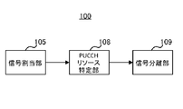
- FIG. 4 is a block diagram illustrating a main configuration of the base station 100 according to the embodiment of the present disclosure.
- signal allocation section 105 allocates a downlink control signal (MPDCCH) including PDSCH resource allocation information to downlink resources (Narrowband).
- the PUCCH resource specifying unit 108 specifies the PUCCH resource to which the ACK / NACK signal for the PDSCH is assigned based on the downlink resource to which the downlink control signal is assigned.
- the signal separation unit 109 separates the ACK / NACK signal included in the identified PUCCH resource from the received signal from the terminal that has transmitted the downlink control signal.
- FIG. 5 is a block diagram illustrating a main configuration of the terminal 200 according to each embodiment of the present disclosure.
- MPDCCH reception section 207 receives a downlink control signal (MPDCCH) including PDSCH resource allocation information.
- the PUCCH resource specifying unit 208 specifies the PUCCH resource to which the ACK / NACK signal for the PDSCH is assigned based on the downlink resource to which the downlink control signal is assigned.
- the signal allocation unit 211 allocates an ACK / NACK signal to the specified PUCCH resource.
- the downlink resource (Narrowband) is composed of a plurality of PRB pairs, and each of the plurality of PRB pairs is assigned either the first PRB set or the second PRB set.
- the PUCCH resource specifying units 108 and 208 use the offset value set in either the first PRB set or the second PRB set. To identify the PUCCH resource.
- FIG. 6 is a block diagram showing a configuration of base station 100 according to the present embodiment.
- the base station 100 includes an aggregation level setting unit 101, an MPDCCH generation unit 102, an error correction coding unit 103, a modulation unit 104, a signal allocation unit 105, a transmission unit 106, and a reception unit 107.
- the aggregation level setting unit 101 sets the aggregation level for the MTC terminal based on the reception quality of the MTC terminal held by the base station 100 and the number of MPDCCH information bits (not shown). Aggregation level setting section 101 outputs the set Aggregation level to MPDCCH generating section 102.
- the MPDCCH generating unit 102 generates MPDCCH that is control information addressed to the MTC terminal. Specifically, the MPDCCH generation unit 102 generates MPDCCH information bits, performs error correction coding, and performs rate matching from the Aggregation level input from the Aggregation RE level setting unit 101 and the number of REs that can be used for the MPDCCH. Then, a transmission bit string is generated, and the transmission bit string is output to the signal allocation unit 105.
- the MPDCCH includes, for example, DL allocation information indicating PDSCH resource allocation, UL allocation information indicating PUSCH resource allocation, and the like. Also, the DL allocation information is output to the signal allocation unit 105, and the UL allocation information is output to the signal separation unit 109.
- the error correction coding unit 103 performs error correction coding on the transmission data signal (DL data signal) or higher layer signaling, and outputs the encoded signal to the modulation unit 104.
- Modulation section 104 performs modulation processing on the signal received from error correction coding section 103 and outputs the modulated data signal to signal allocation section 105.
- the signal allocation unit 105 allocates a signal (including a data signal) received from the modulation unit 104 and a control signal (MPDCCH) received from the MPDCCH generation unit 102 to a predetermined downlink resource. For example, if the aggregation level of MPDCCH is 1,2,4,8, the signal allocation unit 105 allocates the MPDCCH to either PRB set0 or PRB set 1 in the narrowband, and if the aggregation level of MPDCCH is 16. , MPDCCH is allocated to PRB set having 4 PRBs. Further, when the aggregation level is 24 (24ECCEs), the signal allocation unit 105 allocates MPDCCH to all ECCEs in the narrowband across the PRBs set0 and PRBs set1 in the narrowband.
- MPDCCH control signal
- the signal allocation unit 105 allocates a signal for the MTC terminal among the transmission data signal and higher layer signaling to the narrowband. In this way, the control signal (MPDCCH) and the data signal (PDSCH) are assigned to predetermined resources, thereby forming a transmission signal. The formed transmission signal is output to transmission section 106. Further, the signal allocation unit 105 specifies allocation information (for example, the PRB set number, the minimum ECCE number, and the ARO included in the DL allocation information in which the MPDCCH is allocated) indicating the resource to which the MPDCCH is allocated as the PUCCH resource identification To the unit 108.
- allocation information for example, the PRB set number, the minimum ECCE number, and the ARO included in the DL allocation information in which the MPDCCH is allocated
- the transmission unit 106 performs radio transmission processing such as up-conversion on the transmission signal input from the signal allocation unit 105 and transmits the transmission signal to the terminal 200 via the antenna.
- the receiving unit 107 receives a signal transmitted from the terminal 200 via an antenna, performs wireless reception processing such as down-conversion on the received signal, and outputs the signal to the signal separation unit 109.
- the PUCCH resource specifying unit 108 is assigned an ACK / NACK signal for the data signal (PDSCH) indicated by the MPDCCH based on the downlink resource to which the MPDCCH indicated by the assignment information input from the signal assignment unit 105 is assigned. Identify PUCCH resources.
- the PUCCH resource specifying unit 108 outputs information indicating the specified PUCCH resource to the signal separating unit 109. The details of the PUCCH resource specifying method in the PUCCH resource specifying unit 108 will be described later.
- the signal separation unit 109 separates the UL data signal from the received signal based on the information input from the MPDCCH generation unit 102 and outputs the UL data signal to the demodulation unit 111. Further, signal separation section 109 separates a signal (including ACK / NACK signal) included in the PUCCH resource from the received signal based on the information input from PUCCH resource specifying section 108 and outputs the signal to PUCCH reception section 110 To do.
- the PUCCH reception unit 110 determines ACK and NACK from the signal (PUCCH) input from the signal separation unit 109 and notifies the higher layer.
- the demodulation unit 111 performs demodulation processing on the signal input from the signal separation unit 109 and outputs the obtained signal to the error correction decoding unit 112.
- the error correction decoding unit 112 decodes the signal input from the demodulation unit 111 and obtains a received data signal from the terminal 200.
- FIG. 7 is a block diagram showing a configuration of terminal 200 according to the present embodiment.
- terminal 200 includes reception section 201, signal separation section 202, demodulation section 203, error correction decoding section 204, error determination section 205, ACK / NACK generation section 206, and MPDCCH reception section 207.
- a PUCCH resource specifying unit 208 an error correction coding unit 209, a modulation unit 210, a signal allocation unit 211, and a transmission unit 212.
- the receiving unit 201 identifies which Narrowband in the system band the signal is allocated based on a predetermined pattern or information (not shown) notified in a higher layer, and retuning the identified Narrowband To do. Then, the reception unit 201 receives the reception signal via the antenna, outputs the reception signal to the signal separation unit 202 after performing reception processing such as down-conversion on the reception signal.
- the signal separation unit 202 outputs a signal (MPDCCH signal) arranged in the PRB to which the MPDCCH may be assigned to the MPDCCH reception unit 207.
- signal separation section 202 separates the DL data signal and higher layer signaling from the received signal based on the DL allocation information input from MPDCCH reception section 207 and outputs the result to demodulation section 203.
- the demodulator 203 demodulates the signal received from the signal separator 202 and outputs the demodulated signal to the error correction decoder 204.
- the error correction decoding unit 204 decodes the demodulated signal received from the demodulating unit 203 and outputs the obtained received data signal.
- the received data signal is output to error determination section 205.
- the error determination unit 205 detects an error from the CRC of the received data signal and outputs the detection result to the ACK / NACK generation unit 206.
- ACK / NACK generation section 206 Based on the detection result of the received data signal input from error determination section 205, ACK / NACK generation section 206 generates an ACK if there is no error, generates a NACK if there is an error, and generates the generated ACK / NACK / NACK The NACK signal is output to the upper layer and the signal allocation unit 211.
- the MPDCCH receiving unit 207 assigns the MPDCCH signal received from the signal demultiplexing unit 202 to all ECCEs in the narrowband across the search space for PRB set0 and PRBPRset1, and across PRB set0 and PRB set1. And MPDCCH which is a control signal including DL allocation information or UL allocation information is detected.
- MPDCCH reception section 207 outputs DL allocation information detected as a signal addressed to the terminal itself to signal separation section 202, and outputs UL allocation information to signal allocation section 211.
- the MPDCCH receiving unit 207 outputs, to the PUCCH resource specifying unit 208, the allocation information indicating the PRB set number, the minimum ECCE number, and the ARO included in the DL allocation information in which the MPDCCH is arranged.
- the PUCCH resource specifying unit 208 based on the allocation information (PRB set number, minimum ECCE number, ARO) input from the MPDCCH receiving unit 207, and N_pucch information notified in advance in the higher layer, The PUCCH resource to which NACK is allocated is specified.
- PUCCH resource identifying unit 208 outputs information indicating the identified PUCCH resource to signal allocating unit 211. The details of the PUCCH resource specifying method in the PUCCH resource specifying unit 208 will be described later.
- the error correction coding unit 209 performs error correction coding on the transmission data signal (UL data signal), and outputs the encoded data signal to the modulation unit 210.
- Modulation section 210 modulates the data signal received from error correction coding section 209 and outputs the modulated data signal to signal allocation section 211.
- the signal allocation unit 211 allocates the data signal input from the modulation unit 210 to a resource based on the UL allocation information received from the MPDCCH reception unit 207, and outputs the resource to the transmission unit 212. Also, the signal allocation unit 211 allocates the ACK / NACK signal input from the ACK / NACK generation unit 206 to the PUCCH resource based on the PUCCH resource allocation information input from the PUCCH resource specification unit 208, and transmits the transmission unit 212. Output to.
- the transmission unit 212 identifies a resource corresponding to the narrowband to which the UL data is allocated based on a predetermined pattern and performs retuning. And the transmission part 212 performs transmission processing, such as up-conversion, with respect to the signal input from the signal allocation part 211, and transmits via an antenna.
- base station 100 (PUCCH resource specifying unit 108) and terminal 200 (PUCCH resource specifying unit 208) are configured such that MPDCCH is arranged across a plurality of PRB sets (4PRB sets and 2PRB sets).
- MPDCCH is arranged across a plurality of PRB sets (4PRB sets and 2PRB sets).
- N_pucch an offset value
- the terminal 200 identifies a PUCCH resource using N_pucch corresponding to 2PRB set assigned to PRB # 0.
- terminal 200 identifies a PUCCH resource using N_pucch corresponding to 4PRB set assigned to PRB # 0.
- base station 100 sets the offset value (MTCMTN_pucch) set in the PRB set assigned to the PRB pair with the smallest PRB number among the PRB sets in the narrowband to which MPDCCH is assigned. To identify the PUCCH resource to which the ACK / NACK signal is assigned.
- MTCMTN_pucch the offset value
- the offset value N_pucch set in the MPDCCH of 24ECCEs differs according to the allocation of the PRDC set of the MPDCCH to the PRB pair.
- the PUCCH resource corresponding to the MPDCCH of 24ECCEs can be switched by the allocation of the PRDC set of the MPDCCH.
- FIG. 8 shows an example of PUCCH resource allocation when two Narrowbands 1 and 3 are used for different MTC terminals (terminal 200), and MPDCCH of 24ECCEs is detected in both Narrowbands.
- N_pucch, 0 is set in 2PRB set
- N_pucch, 1 is set in 4PRB set.
- the allocation of PRB set differs between the two narrowbands shown in FIG. Specifically, in Narrowband 1, 2PRB set is assigned to PRB pair # 0 and # 1 and 4PRB set is assigned to PRB pair # 2 to # 5, as in FIG. 2A.
- 2PRB ⁇ set is assigned to PRB pair # 14 and # 15, and 4PRB set is assigned to PRB pair # 12, # 13, # 16, and # 17, as in FIG. 2B.
- the MTC terminal using Narrowband 1 specifies the PUCCH resource using N_pucch, 0 set in 2 PRB set assigned to PRB pair # 0 with the smallest PRB number.
- an MTC terminal using Narrowband 3 specifies a PUCCH resource using N_pucch, 1 set to 4PRB 1 set assigned to PRB 8 pair # 12 having the smallest PRB number.
- each MTC terminal uses a different N_pucch to identify PUCCH resources. Can be prevented.
- N_pucch, 0 is N_pucch set for PRB set 0 (first PRB set). Which PRB set is PRB set 0 or PRB set 1 among 2PRB set and 4PRB set is instructed when setting in an upper layer (RRC signaling), or one PRB set is set as PRB set 0 It may be determined in advance. Also, N_pucch, 0 and N_pucch, 1 are reported to terminal 200 in the upper layer (RRC signaling).
- the upper layer signaling may be MTC SIB that can be commonly received by MTC terminals, or individual terminal 200 signaling.
- the base station 100 uses the offset value (N_pucch, 0) set to the PRB set with the smallest PRB set number among the PRB sets in the narrowband to which MPDCCH is allocated, and ACK. Specify the PUCCH resource to which the / NACK signal is assigned.
- N_pucch 0 is always used regardless of which PRB pair is assigned to each PRB set in Narrowband.
- N_pucch 0 when specifying the PUCCH resource corresponding to the MPDCCH of 24 ECCEs.
- N_pucch, 1 is used to specify the PUCCH resource.
- PUCCH resources can be reduced by setting N_pucch, 1 to a value smaller than N_pucch, 0.
- the MTC terminal when the MTC terminal detects the MPDCCH of 24ECCEs, it may be determined that the PUCCH resource is specified using a smaller value of N_pucch, 0 and N_pucch, 1. In this case, PUCCH resource reduction can be realized regardless of the magnitude relationship of N_pucch, 0 and N_pucch, 1.
- the MTC terminal when the MTC terminal detects an MPDCCH of 24ECCEs, it may be determined that the PUCCH resource is specified using N_pucch corresponding to 4PRB set or N_pucch corresponding to 2PRB set. In this case, the PUCCH resource can be reduced by setting N_pucch corresponding to 4PRB set or N_pucch for 2PRB set to a small value.
- base station 100 and terminal 200 correspond to any of a plurality of PRB set q in which the MPDCCH is arranged.
- PUCCH resource is identified using N_pucch, q.
- the base station 100 and the terminal 200 can specify the PUCCH resource corresponding to the MPDCCH arranged across a plurality of PRB sets like 24ECCEs without adding new signaling. . That is, according to the present embodiment, it is possible to efficiently specify the PUCCH resource when one MPDCCH is allocated to all 6PRB pairs in the narrowband.
- MPDCCH in the MPDCCH arrangement of Option2, in the above operation example, it is assumed that PRB set 0 (first PRB set) notified by the higher layer is 4PRB set and PRB set 1 (second PRB set) is 2PRB set, Although the case where MPDCCH is arranged first in 4PRB set is illustrated, MPDCCH may be arranged first in PRB set 1 (second PRB set).
- the base station and terminal according to the present embodiment have the same basic configuration as base station 100 and terminal 200 according to Embodiment 1, and will be described with reference to FIGS.
- Embodiment 1 the case where it is assumed that different offset values N_pucch are set for a plurality of PRBsets has been described.
- a case will be described where it is assumed that a common offset value N_pucch is set for a plurality of PRB sets.
- N PUCCH (e1) (hereinafter abbreviated as “N_pucch”) is set in the PRB set for the PUCCH of MTC terminals at the same repetition level, and the PUCCH resource from the ECCE number is set for each PRB set. Identified.
- the PUCCH resource (resource number) for transmitting PUCCH format 1a / 1b is specified by the following equation.
- K 0 0
- K 1 1
- PRB set 0 4PRB set (16ECCE)
- K 1 16
- PRB set 1 2PRB set (8ECCE)
- K 1 8.
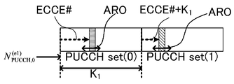
- FIG. 9 shows a conceptual diagram of the PUCCH resource of the present embodiment.
- the PUCCH resource (PUCCH set (0)) corresponding to PRB set 0 is specified using N_pucch and ECCE number
- the PUCCH resource (PUCCH set (1)) corresponding to PRB set 1 is N_pucch. It is specified using + ECCE number + K 1 (where K 1 is the number of ECCEs in PUCCH set (0)).
- K 1 is the number of ECCEs in PUCCH set (0).
- the base station 100 and the terminal 200 specify a PUCCH resource corresponding to an MPDCCH (24ECCEs MPDCCH) arranged across a plurality of PRB sets using a common N_pucch.
- the base station 100 and the terminal 200 identify the PUCCH resource corresponding to the MPDCCH of 24ECCEs based on the common N_pucch, thereby supporting the MPDCCH of 24ECCEs regardless of the allocation of the MPDCCH PRB set to the PRB pair.
- a PUCCH resource a PUCCH resource with a low resource number can always be set.
- base station 100 and terminal 200 are arranged across a plurality of PRB sets, such as 24ECCEs, without adding new signaling.
- a PUCCH resource corresponding to MPDCCH can be specified. That is, according to the present embodiment, it is possible to efficiently specify the PUCCH resource when one MPDCCH is allocated to all 6PRB pairs in the narrowband.
- the PUCCH resource corresponding to the PRB set is changed for each PRB set q using the variable K q .
- the PUCCH resource is shared between PRB set qs without using K q. May be.
- the collision of PUCCH resources between PRB set qs can be avoided by ARO.
- MPDCCH having a high aggregation level such as MPDCCH of 24ECCEs
- the amount of PUCCH resources can be reduced by sharing the PUCCH resources between PRB set qs.
- the PUCCH resource when 24ECCEs MPDCCH is detected can be obtained by the same equation as in the operation example 3.
- the K 1 there has been described a case where the ECCE number included in the PRB set0, the value of K 1 is not limited thereto, 1/2 ECCE number of contained PRB set0 A value such as If K 1 is set to a small value such as 1/2 the number of ECCEs, the total amount of PUCCH resources can be reduced. This is effective, for example, when the collision probability of PUCCH resources is low.
- Misrecognition 1 may occur when the number of transmittable bits calculated from the number of REs that can be used for MPDCCH in PRB set 0 is an integral multiple of the number of bits after MPDCCH encoding.
- misrecognition 2 is a case where the number of transmittable bits calculated from the number of REs that can be used for MPDCCH in PRB set 1 is an integral multiple of the number of bits after MPDCCH encoding, in addition to the above conditions of misrecognition 1 Can happen.
- FIG. 10 shows a case where the number of bits after MPDCCH encoding (After) encodingMPbits) is equal to the number of bits that can be transmitted in Aggregation level 8 (8ECCEs). Therefore, the transmission bit string of 24ECCEs is generated as a bit string obtained by copying the encoded bit twice and multiplying it by 3 times by Rate matching. As shown in FIG. 10, the generated transmission bit string is arranged in 16ECCE of 4PRB set which is PRB set 0, and then arranged in 8ECCE of 2PRB set which is PRB set 1.
- the first 16ECCE and second 8ECCE transmission bit sequences of the 24ECCEs transmission bit sequence shown in FIG. 10 are erroneously received as 16ECCE or 8ECCE by the MTC terminal if the reception quality at the MTC terminal is high (that is, the 16ECCE or 8ECCE is erroneously received). Recognized bit string).
- the above misrecognition is that the actual reception quality at the MTC terminal is higher than the reception quality of the MTC terminal expected at the base station, and at the MTC terminal, the Aggregation level 16 of 4 PRB set that is an aggregation level lower than 24ECCEs Occurs when MPDCCH can be received at Aggregation level 8 of 2PRB set.
- this misrecognition of Aggregation level occurs, there is a problem that PUCCH resources are mistaken.
- the MTC terminal ACK / NACK is transmitted using the PUCCH resource specified from N_pucch corresponding to Aggregation level 16 of 4PRB set or Aggregation level 8 of 2PRB set.
- the MTC terminal when the MTC terminal recognizes that it has received MPPRCH of 4PRB set Aggregation level 16, the PUCCH resource (PUCCH set (0)) specified using N_pucch, 0 set in 4PRB set PUCCH resource (PUCCH set (1)) specified using N_pucch, 1 set in 2PRB ⁇ set when ACK / NACK is transmitted using, and when 2PRB PRset Aggregation level 8 MPDCCH is received ACK / NACK is transmitted using
- the MTC terminal cannot transmit ACK / NACK in the PUCCH resource corresponding to 24ECCEs originally planned by the base station.
- the base station may attempt to receive ACK / NACK with the PUCCH resource corresponding to the scheduled 24ECCEs, and may erroneously detect ACK / NACK.
- an MTC terminal may interfere with a signal transmitted by another terminal by transmitting ACK / NACK with an unplanned PUCCH resource.
- Option 1 frequency precedence
- 24ECCEs of MPDCCH is arranged across 4PRB set and 2PRB set in units of OFDM symbol, and 4PRB set Aggregation level 16 MPDCCH or 2PRB set Aggregation level 8
- 4PRB set Aggregation level 16 MPDCCH or 2PRB set Aggregation level 8 The above-mentioned problem regarding misrecognition does not occur because the arrangement of MPDCCH in RE is different from MPDCCH.
- base station and terminal according to the present embodiment have the same basic configuration as base station 100 and terminal 200 according to Embodiment 1, and will be described with reference to FIGS. 6 and 7.
- the terminal 200 can obtain the PUCCH reserved for the MPDCCH of 24ECCEs.
- ACK / NACK can be transmitted using resources. Therefore, it is possible to avoid the terminal 200 from erroneously using the PUCCH resource when erroneous recognition 1 occurs.
- the number of PRB-pairs to which PRB-set 0 where MPDCCH is allocated first is allocated may be larger than the number of PRB-pairs where PRB-set 1 where MPDCCH is allocated is allocated.
- PRB set 0 may be 4PRB set and PRB set 1 may be 2PRB set.
- PRBPRset 0 is 4PRB set and PRB set 1 is 2PRB set
- the terminal 200 detects the MPDCCH of 24ECCEs
- the PUCCH resource is set using N_puuch, 0 set to PRB set 0.
- base station 100 and terminal 200 specify a PUCCH resource using an offset value N_pucch set in PRB set where MPDCCH is placed first.
- the base station 100 and the terminal 200 can add PUCCH resources corresponding to MPDCCHs arranged across a plurality of PRB ⁇ ⁇ sets, such as 24ECCEs, without adding new signaling. Can be identified. That is, it is possible to efficiently specify the PUCCH resource when one MPDCCH is allocated to all 6PRB pairs in the narrowband.
- the terminal 200 In the operation example 5, in addition to the operation of the operation example 4, in order to avoid erroneous PUCCH resources due to the misrecognition 2, the terminal 200 (MTC terminal) detects the MPDCCH at the maximum aggregation level of the PRB set. , N_pucch, 0 is used to identify the PUCCH resource.
- the terminal 200 identifies the PUCCH resource using N_pucch, 0, and when the MPDCCH is detected at another aggregation level of PRB set 1, PUCCH resource is specified using N_pucch, 1 set to.
- MPDCCH is detected at the maximum aggregation level of PRB set 0
- MPDCCH is detected at the maximum aggregation level of PRB set 1.
- the PUCCH resource is specified using N_pucch, 0.
- the PUCCH resource used for transmitting the ACK / NACK signal is the same resource as in the case where no erroneous detection is performed. Can be avoided.
- PRB set 1 uses N_pucch, 0 only when the MTC terminal detects MPDCCH at the maximum Aggregation level, and uses N_pucch, 1 when the MTC terminal detects MPDCCH at another AggregationAlevel. Therefore, in other aggregations other than the maximum aggregation of PRB set 1, even if the base station 100 transmits MPDCCH including ECCE # 0, the collision probability with the PUCCH resource of PRB set 0 applies the operation example 5 It does not change compared with the case where it does not.
- mapping method of MPDCCH to RE when 24 ECCESs are assigned to MPDCCH, they are assigned in the order of PRB set 0, PRB set1. Also, PRB set 0 is 4PRB set, and PRB set 1 is 2PRB set.
- MPDCCH is transmitted at the maximum aggregation level of PRB set 1 (here 2PRB set), in the same manner as EPDCCH, MPDCCH is transmitted from OFDM symbol with a lower OFDM symbol number within PRB set 1 (2PRB set). After the PRB pair is vertically arranged and arranged from the lowest frequency to the higher frequency, it moves to the next OFDM symbol, and similarly, the PRB pair is arranged longitudinally and arranged from the lowest frequency to the higher one.
- Example 1 Mirroring
- MPDCCH starts from the OFDM symbol with the lower OFDM symbol number by cutting the PRB pair vertically. After arranging from the higher one to the lower one, the process proceeds to the next OFDM symbol, and similarly, the PRB pair is longitudinally arranged from the higher frequency to the lower one. That is, in Mirroring, the arrangement order of MPDCCHs in the frequency direction in each OFDM symbol is inverted between 24ECCEs and the maximum aggregation level of PRB set 1.
- the arrangement order of MPDCCH in PRB set 1 is different between the case where MPDCCH of 24ECCEs is arranged and the case where MPDCCH of maximum aggregation of PRB set 1 is arranged. Therefore, Aggregation level is erroneously detected in the MTC terminal. You can avoid that.
- PRB pair shifting when 24ECCEs of MPDCCH is arranged, MPDCCH is arranged by shifting the PRB pair number in PRB set 1 (2PRB set). For example, in FIG. 12B, since 2 PRB sets are allocated to PRB pair # 0 and PRB pair # 1, for the 24DCCEs MPDCCH, PRB pair # The arrangement of MPDCCH is switched between 0 and PRB pair # 1.
- the arrangement order of MPDCCH in PRB set 1 is different between the case where MPDCCH of 24ECCEs is arranged and the case where MPDCCH of maximum aggregation of PRB set 1 is arranged. Therefore, Aggregation level is erroneously detected in the MTC terminal. You can avoid that.
- Example 3 OFDM symbol shifting
- MPDCCHs are allocated with shifted OFDM symbol numbers in PRB set 1 (2PRB set).
- FIG. 12C shows an example of shifting the OFDM symbol number by three.
- MPDCCH moves from OFDM symbol # 3 to PRB pair by traversing PRB pair from the lowest frequency to the higher frequency, and then moves to the next OFDM symbol. Is arranged from low to high frequency. Then, when the OFDM symbol in which MPDCCH is arranged becomes the final OFDM symbol, it moves to the first OFDM symbol # 0 and moves to OFDM symbol # 2.
- the arrangement order of MPDCCH in PRB set 1 is different between the case where MPDCCH of 24ECCEs is arranged and the case where MPDCCH of maximum aggregation of PRB set 1 is arranged. Therefore, Aggregation level is erroneously detected in the MTC terminal. You can avoid that.
- terminal 200 even when terminal 200 erroneously detects MPDCCH aggregation level, it specifies the same PUCCH resource as when it is not erroneously detected, or terminal 200 sets MPDCCH aggregation level. It is possible to prevent erroneous detection. By doing so, erroneous detection of the ACK / NACK signal at the base station 100 can be avoided. Also, since terminal 200 transmits ACK / NACK with the correct PUCCH resource, it is possible to avoid interference with signals transmitted by other terminals.
- Embodiments 1 and 2 described above an example has been shown in which 4 PRB sets and 2 PRB sets are assigned to non-overlapping PRB pairs in the narrowband. However, there may be a case where 4PRB set and 2PRB set are assigned to overlapping PRB pairs in Narrowband.
- 13A and 13B show an example in which 4 ⁇ ⁇ PRB set is assigned to PRB pair # 2,3,4,5 and 2PRB set is assigned to overlapping PRB pair # 2, # 3.
- the MPDCCH arrangement of 24ECCEs is premised on Option 1 (frequency preceding). In other words, it is not affected by the arrangement of 4PRBNset and 2PRB set.
- the 24DCCEs MPDCCH symbol string is arranged from the OFDM symbol with the lower OFDM symbol number to the PRB pair vertically and from the lowest to the highest frequency. After that, the process moves to the next OFDM symbol, and similarly, the PRB symbol pair is longitudinally arranged from the lower frequency to the higher frequency.
- the operation example 2 of the first embodiment and the operation example 3 of the second embodiment can be applied.
- the PUCCH resource may be specified using N_pucch, 0.
- the PUCCH resource may be specified using N_pucch that is commonly set in a plurality of PRB sets.
- each functional block used in the description of the above embodiment is typically realized as an LSI which is an integrated circuit.
- the integrated circuit may control each functional block used in the description of the above embodiment, and may include an input and an output. These may be individually made into one chip, or may be made into one chip so as to include a part or all of them.
- the name used here is LSI, but it may also be called IC, system LSI, super LSI, or ultra LSI depending on the degree of integration.
- the method of circuit integration is not limited to LSI, and implementation with a dedicated circuit or a general-purpose processor is also possible.
- An FPGA Field Programmable Gate Array
- a reconfigurable processor that can reconfigure the connection and setting of circuit cells inside the LSI may be used.
- the base station includes a signal allocation unit that allocates a downlink control signal including PDSCH (Physical Downlink Shared Shared Channel) resource allocation information to the downlink resource, and an ACK for the PDSCH based on the downlink resource to which the downlink control signal is allocated.
- PDSCH Physical Downlink Shared Shared Channel
- Each of the plurality of PRB pairs is assigned with one of the first PRB set and the second PRB ⁇ set, and the specifying unit receives the downlink control signal.
- the PUCCH resource is specified using the offset value set in either the first PRB set or the second PRB set. Take the deposition.
- different first offset values are set in the first PRB set and the second PRB ⁇ set, respectively, and the specific unit is configured so that the downlink control signal is arranged across the first PRB set and the second PRB set.
- the PUCCH resource is specified using the offset value set in the PRB set assigned to the PRB pair having the smallest PRB number among the first PRB set and the second PRB set.
- different first offset values are set in the first PRB set and the second PRB ⁇ set, respectively, and the specific unit is configured so that the downlink control signal is arranged across the first PRB set and the second PRB set.
- the PUCCH resource is specified using the offset value set in the PRB set having a smaller PRB set number among the first PRB set and the second PRB set.
- different first offset values are set in the first PRB set and the second PRB ⁇ set, respectively, and the specific unit is configured so that the downlink control signal is arranged across the first PRB set and the second PRB set.
- the PUCCH resource is specified using an offset value having a smaller value among the offset value set in the first PRB set and the offset value set in the second PRB set.
- a common offset value is set in the first PRB set and the second PRB set, and the specifying unit specifies the PUCCH resource using the common offset value.
- different first offset values are set in the first PRB set and the second PRB ⁇ set, respectively, and the specific unit is configured so that the downlink control signal is arranged across the first PRB set and the second PRB set.
- the PUCCH resource is specified using the offset value set in the PRB set in which the downlink control signal is arranged first among the first PRB set and the second PRB set.
- the number of PRB pairs to which the PRB set in which the downlink control signal is arranged first is assigned is larger than the number of PRB pairs to which the PRB set in which the downlink control signal is arranged later is assigned.
- a terminal allocates an ACK / NACK signal for a PDSCH based on a receiving unit that receives a downlink control signal including resource allocation information of PDSCH (Physical Downlink Shared Shared Channel) and a downlink resource to which the downlink control signal is allocated.
- PDSCH Physical Downlink Shared Shared Channel
- a signal allocation unit that allocates an ACK / NACK signal to the identified PUCCH resource, and a downlink resource is configured with a plurality of PRB pairs, Each of the PRB pairs is assigned either one of the first PRB ⁇ ⁇ set and the second PRB ⁇ set, and the specifying unit, when the downlink control signal is arranged across the first PRB set and the second PRB set, A configuration is adopted in which a PUCCH resource is specified using an offset value set in any of the second PRB sets.
- a downlink control signal including PDSCH (Physical Downlink Shared Shared Channel) resource allocation information is allocated to a downlink resource, and an ACK / NACK signal for the PDSCH is generated based on the downlink resource to which the downlink control signal is allocated.
- the PUCCH (Physical Uplink Control Channel) resource to be allocated is specified, and the ACK / NACK signal included in the specified PUCCH resource is separated from the received signal from the terminal that has transmitted the downlink control signal.
- the communication method of the present disclosure receives a downlink control signal including resource allocation information of PDSCH (Physical Downlink Shared ⁇ Channel), and PUCCH to which an ACK / NACK signal for PDSCH is assigned based on the downlink resource to which the downlink control signal is assigned (Physical Uplink Control ⁇ Channel) resources are identified, ACK / NACK signals are allocated to the identified PUCCH resources, and downlink resources are configured with a plurality of PRB pairs, and each of the plurality of PRB pairs has a first PRB set and a second PRB.
- the PUCCH resource has an offset value set in either the first PRB set or the second PRB set. To be specified.
- One embodiment of the present disclosure is useful for a mobile communication system.
Abstract
Description
MTC端末向けのPUCCHリソースを特定するためのオフセット(N_pucch)を用いることにより、従来端末及びMTC端末のPUCCHリソースを区別し、PUCCHリソースの衝突を避けることができる。また、N_pucchは、リピティションレベル毎に指示されることで、異なるリピティションレベルのMTC端末間でもPUCCHリソースの衝突を避けることができる。これにより、基地局との距離が異なる端末同士の信号が多重される際に起きる遠近問題を解決することができる。 (Knowledge that became the basis of this disclosure)
By using the offset (N_pucch) for specifying the PUCCH resource for the MTC terminal, it is possible to distinguish the PUCCH resource of the conventional terminal and the MTC terminal and to avoid the collision of the PUCCH resource. Further, when N_pucch is instructed for each repetition level, it is possible to avoid collision of PUCCH resources between MTC terminals having different repetition levels. Thereby, it is possible to solve the perspective problem that occurs when signals of terminals having different distances from the base station are multiplexed.

上述したように、MTCにおいて用いられる24ECCEsのMPDCCHは、Narrowband 内の6PRBpairに含まれる、MPDCCHに使用できる全てのREに配置される。以下では、24ECCEsのMPDCCHの配置方法として考えられる2つのOption 1, 2について説明する。 [Explanation of MTC 24ECCEs]
As described above, the 24DCCEs MPDCCH used in MTC is arranged in all REs that can be used for MPDCCH included in 6PRBpair in Narrowband. In the following, two
Option 1では、24ECCEsのMPDCCHが周波数先行(Frequency first)で配置される。具体的には、Narrowbandにおいて、MPDCCHのシンボル列が、OFDM symbol番号の低いOFDM symbolから、PRB pairを縦断して周波数の低い方から高い方へ配置された後、次のOFDM symbolに移り、同様にPRB pairを縦断して周波数の低い方から高い方へ配置される。 (Option 1: Fig. 2A, Fig. 2B)
In
Option2では、24ECCEsのMPDCCHがNarrowband内のMPDCCH PRB set先行で配置される。したがって、MPDCCHの配置順は、PRB setがどのPRB pairに割り当てられているかによって変更される。 (Option2: Fig. 3A, Fig. 3B)
In
本開示の各実施の形態に係る通信システムは、例えば、LTE-Advancedシステムに対応する基地局100及び端末200を備える。端末200は、例えば、MTC端末である。 [Outline of communication system]
The communication system according to each embodiment of the present disclosure includes, for example, a
[基地局の構成]
図6は、本実施の形態に係る基地局100の構成を示すブロック図である。図6において、基地局100は、Aggregation level設定部101と、MPDCCH生成部102と、誤り訂正符号化部103と、変調部104と、信号割当部105と、送信部106と、受信部107と、PUCCHリソース特定部108と、信号分離部109と、PUCCH受信部110と、復調部111と、誤り訂正復号部112と、を有する。 (Embodiment 1)
[Base station configuration]
FIG. 6 is a block diagram showing a configuration of
図7は、本実施の形態に係る端末200の構成を示すブロック図である。図7において、端末200は、受信部201と、信号分離部202と、復調部203と、誤り訂正復号部204と、誤り判定部205と、ACK/NACK生成部206と、MPDCCH受信部207と、PUCCHリソース特定部208と、誤り訂正符号化部209と、変調部210と、信号割当部211と、送信部212と、を有する。 [Terminal configuration]
FIG. 7 is a block diagram showing a configuration of
以上の構成を有する基地局100及び端末200における動作について詳細に説明する。 [Operations of
Operations in
動作例1では、端末200(MTC端末)は、Option 1,2の何れにおいても、24ECCEsのMPDCCHを検出した場合、Narrowband内のPRB setのうち、PRB番号が最小のPRB pairに割り当てられたPRB setに設定されたオフセット値(MTC N_pucch)を用いてPUCCHリソースを特定する。 (Operation example 1)
In the first operation example, when the terminal 200 (MTC terminal) detects the MPDCCH of 24ECCEs in both
動作例2では、端末200(MTC端末)は、Option 1,2の何れにおいても、24ECCEsのMPDCCHを検出した場合、Narrowband内のPRB setのうち、PRB set番号が最小のPRB setに設定されたオフセット値(N_pucch,0)を用いてPUCCHリソースを特定する。 (Operation example 2)
In the operation example 2, when the terminal 200 (MTC terminal) detects the MPDCCH of 24ECCEs in both
なお、動作例2において、MTC端末が24ECCEsのMPDCCHを検出した場合、N_pucch,1を使用してPUCCHリソースを特定すると定めてもよい。この場合、N_pucch,1をN_pucch,0よりも小さい値とすることで、PUCCHリソースの縮小を実現できる。 (Modification of Operation Example 2)
In the second operation example, when the MTC terminal detects the MPDCCH of 24ECCEs, it may be determined that N_pucch, 1 is used to specify the PUCCH resource. In this case, PUCCH resources can be reduced by setting N_pucch, 1 to a value smaller than N_pucch, 0.
本実施の形態に係る基地局及び端末は、実施の形態1に係る基地局100及び端末200と基本構成が共通するので、図6及び図7を援用して説明する。 (Embodiment 2)
The base station and terminal according to the present embodiment have the same basic configuration as
動作例3では、基地局100及び端末200(MTC端末)は、Option 1,2の何れにおいても、24ECCEsのMPDCCHを検出した場合、Narrowband内の複数のPRB setに共通に設定されたN_pucchを用いてPUCCHリソースを特定する。このとき、4PRB set及び2PRB setがどのPRB pairに割り当てられているかに依らず、Kq=0とする。また、24ECCEsのMPDCCHを用いる場合の最小ECCE番号をnECCE,q=0と仮定する場合、PUCCHリソース(リソース番号)は、以下の式で特定される。 (Operation example 3)
In the operation example 3, when the
Option2で説明したように24ECCEsのMPDCCHをNarrowband内のMPDCCH PRB set先行で割り当てる場合、MTC端末が、MPDCCHが先に配置されたMPDCCH PRB setの最大Aggregation levelの信号を受信したと誤るケース(以下、「誤認識1」と呼ぶ)、及び、MPDCCHが2番目に配置されたMPDCCH PRB setの最大Aggregation levelの信号を受信したと誤るケース(以下、「誤認識2」と呼ぶ)がある。 (Embodiment 3)
As described in
動作例4では、端末200(MTC端末)が24ECCEsのMPDCCHを検出した場合、Narrowband内の複数のPRB setのうち、24ECCEsのMPDCCHが先に配置されるPRB set qに設定されたN_puuch,qを用いてPUCCHリソースを特定する。例えば、24ECCEsのMPDCCHがPRB set 0に先に配置され、その後、PRB set 1に配置される場合、端末200は、24ECCEsのMPDCCHを検出した場合、PRB set 0に設定されたN_puuch,0を用いてPUCCHリソースを特定する。 (Operation example 4)
In the operation example 4, when the terminal 200 (MTC terminal) detects the MPDCCH of 24ECCEs, among the plurality of PRB sets in the narrowband, N_puuch, q set in the PRB set q in which the 24DCCEs MPDCCH is arranged first is set. To identify the PUCCH resource. For example, when MPDCCH of 24ECCEs is arranged first in PRB set 0 and then arranged in PRB set 1, when detecting MPDCCH of 24ECCEs, terminal 200 uses N_puuch, 0 set in PRB set 0 To identify the PUCCH resource.
動作例5では、動作例4の動作に加えて、誤認識2によってPUCCHリソースを誤ることを回避するために、端末200(MTC端末)は、MPDCCHをPRB setの最大Aggregation levelで検出した場合に、N_pucch,0を使用してPUCCHリソースを特定する。 (Operation example 5)
In the operation example 5, in addition to the operation of the operation example 4, in order to avoid erroneous PUCCH resources due to the
動作例6では、誤検出2を回避するために、基地局100は、24ECCEsのMPDCCHを配置する場合、REにマッピングする順番を、PRB set 1の最大Aggregation levelでのREのマッピングと異ならせる。MPDCCHのREへのマッピングの順番を変えることで、24ECCEsのMPDCCHが送信された場合に、端末200(MTC端末)においてPRB set 1の最大Aggregation levelとして誤検出されることを回避できる。 (Operation example 6)
In the operation example 6, in order to avoid the
Mirroringでは、図12Aに示すように、24ECCEsのMPDCCHが配置される際に、PRB set 1(2PRB set)内では、MPDCCHは、OFDM symbol番号の低いOFDM symbolから、PRB pairを縦断して周波数の高い方から低い方へ配置した後、次のOFDM symbolに移り、同様にPRB pairを縦断して周波数の高い方から低い方へ配置される。つまり、Mirroringでは、24ECCEsの場合と、PRB set 1の最大Aggregation levelの場合とで、各OFDM symbolにおける周波数方向のMPDCCHの配置順が反転している。 (Example 1: Mirroring)
In Mirroring, as shown in FIG. 12A, when 24ECCEs of MPDCCH is arranged, within PRB set 1 (2PRB set), MPDCCH starts from the OFDM symbol with the lower OFDM symbol number by cutting the PRB pair vertically. After arranging from the higher one to the lower one, the process proceeds to the next OFDM symbol, and similarly, the PRB pair is longitudinally arranged from the higher frequency to the lower one. That is, in Mirroring, the arrangement order of MPDCCHs in the frequency direction in each OFDM symbol is inverted between 24ECCEs and the maximum aggregation level of PRB set 1.
PRB pair shiftingでは、24ECCEsのMPDCCHが配置される際に、PRB set 1(2PRB set)内において、MPDCCHは、PRB pair番号をシフトして配置される。例えば、図12Bでは、PRB pair#0とPRB pair#1とに2PRB setが割り当てられているので、24ECCEsのMPDCCHに対しては、PRB set 1の最大Aggregation levelの場合に対して、PRB pair#0とPRB pair#1とでMPDCCHの配置が入れ替わる。 (Example 2: PRB pair shifting)
In PRB pair shifting, when 24ECCEs of MPDCCH is arranged, MPDCCH is arranged by shifting the PRB pair number in PRB set 1 (2PRB set). For example, in FIG. 12B, since 2 PRB sets are allocated to
OFDM symbol shiftingでは、24ECCEsのMPDCCHが配置される際に、PRB set 1(2PRB set)内において、MPDCCHは、OFDMシンボル番号をシフトして配置される。例えば、図12Cでは、OFDM symbol番号を3つシフトする例を示す。つまり、PRB set 1(2PRB set)内では、MPDCCHは、OFDM symbol#3から、PRB pairを縦断して周波数の低い方から高い方へ配置した後、次のOFDM symbolに移り、同様にPRB pairを縦断して周波数の低い方から高い方へ配置される。そして、MPDCCHが配置されるOFDM symbolが最終OFDMシンボルになると、先頭のOFDMシンボル#0へ移り、OFDM symbol#2まで移る。 (Example 3: OFDM symbol shifting)
In OFDM symbol shifting, when 24 ECCES MPDCCHs are allocated, MPDCCHs are allocated with shifted OFDM symbol numbers in PRB set 1 (2PRB set). For example, FIG. 12C shows an example of shifting the OFDM symbol number by three. In other words, within PRB set 1 (2PRB set), MPDCCH moves from
101 Aggregation level設定部
102 MPDCCH生成部
103,209 誤り訂正符号化部
104,210 変調部
105,211 信号割当部
106,212 送信部
107,201 受信部
108,208 PUCCHリソース特定部
109,202 信号分離部
110 PUCCH受信部
111,203 復調部
112,204 誤り訂正復号部
200 端末
205 誤り判定部
206 ACK/NACK生成部
207 MPDCCH受信部 DESCRIPTION OF
Claims (10)
- PDSCH(Physical Downlink Shared Channel)のリソース割当情報を含む下り制御信号を、下りリソースに割り当てる信号割当部と、
前記下り制御信号が割り当てられた下りリソースに基づいて、前記PDSCHに対するACK/NACK信号が割り当てられるPUCCH(Physical Uplink Control Channel)リソースを特定する特定部と、
前記下り制御信号を送信した端末からの受信信号から、前記特定されたPUCCHリソースに含まれる前記ACK/NACK信号を分離する信号分離部と、
を具備し、
前記下りリソースは複数のPRB pairで構成され、前記複数のPRB pairの各々には、第1PRB set及び第2PRB setの何れかが割り当てられ、
前記特定部は、前記下り制御信号が前記第1PRB set及び前記第2PRB setに跨がって配置される場合、前記第1PRB set及び前記第2PRB setの何れかに設定されたオフセット値を用いて、前記PUCCHリソースを特定する、
基地局。 A signal allocation unit that allocates downlink control signals including resource allocation information of PDSCH (Physical Downlink Shared Channel) to downlink resources;
Based on a downlink resource to which the downlink control signal is allocated, a specifying unit that identifies a PUCCH (Physical Uplink Control Channel) resource to which an ACK / NACK signal for the PDSCH is allocated;
A signal separation unit that separates the ACK / NACK signal included in the identified PUCCH resource from a reception signal from a terminal that has transmitted the downlink control signal;
Comprising
The downlink resource is composed of a plurality of PRB pairs, and each of the plurality of PRB pairs is assigned one of a first PRB set and a second PRB set,
When the downlink control signal is arranged across the first PRB set and the second PRB set, the specifying unit uses an offset value set in either the first PRB set or the second PRB set. Identify the PUCCH resource;
base station. - 前記第1PRB set及び前記第2PRB setには、互いに異なるオフセット値がそれぞれ設定され、
前記特定部は、前記下り制御信号が前記第1PRB set及び前記第2PRB setに跨がって配置される場合、前記第1PRB set及び前記第2PRB setのうち、PRB番号が最小のPRB pairに割り当てられたPRB setに設定されたオフセット値を用いて、前記PUCCHリソースを特定する、
請求項1に記載の基地局。 Different offset values are set in the first PRB set and the second PRB set,
When the downlink control signal is arranged across the first PRB set and the second PRB set, the specifying unit assigns the PRB pair having the smallest PRB number among the first PRB set and the second PRB set. Identify the PUCCH resource using the offset value set in the assigned PRB set,
The base station according to claim 1. - 前記第1PRB set及び前記第2PRB setには、互いに異なるオフセット値がそれぞれ設定され、
前記特定部は、前記下り制御信号が前記第1PRB set及び前記第2PRB setに跨がって配置される場合、前記第1PRB set及び前記第2PRB setのうち、PRB set番号が小さいPRB setに設定されたオフセット値を用いて、前記PUCCHリソースを特定する、
請求項1に記載の基地局。 Different offset values are set in the first PRB set and the second PRB set,
When the downlink control signal is arranged across the first PRB set and the second PRB set, the specifying unit sets a PRB set having a smaller PRB set number among the first PRB set and the second PRB set. The PUCCH resource is identified using the offset value that has been
The base station according to claim 1. - 前記第1PRB set及び前記第2PRB setには、互いに異なるオフセット値がそれぞれ設定され、
前記特定部は、前記下り制御信号が前記第1PRB set及び前記第2PRB setに跨がって配置される場合、前記第1PRB setに設定されたオフセット値及び前記第2PRB setに設定されたオフセット値のうち、値が小さいオフセット値を用いて、前記PUCCHリソースを特定する、
請求項1に記載の基地局。 Different offset values are set in the first PRB set and the second PRB set,
When the downlink control signal is arranged across the first PRB set and the second PRB set, the specifying unit includes an offset value set in the first PRB set and an offset value set in the second PRB set. Identify the PUCCH resource using an offset value having a small value,
The base station according to claim 1. - 前記第1PRB set及び前記第2PRB setには、共通のオフセット値が設定され、
前記特定部は、前記共通のオフセット値を用いて前記PUCCHリソースを特定する、
請求項1に記載の基地局。 A common offset value is set in the first PRB set and the second PRB set,
The specifying unit specifies the PUCCH resource using the common offset value.
The base station according to claim 1. - 前記第1PRB set及び前記第2PRB setには、互いに異なるオフセット値がそれぞれ設定され、
前記特定部は、前記下り制御信号が前記第1PRB set及び前記第2PRB setに跨がって配置される場合、前記第1PRB set及び前記第2PRB setのうち、前記下り制御信号が先に配置されるPRB setに設定されたオフセット値を用いて、前記PUCCHリソースを特定する、
請求項1に記載の基地局。 Different offset values are set in the first PRB set and the second PRB set,
When the downlink control signal is arranged across the first PRB set and the second PRB set, the specifying unit arranges the downlink control signal first among the first PRB set and the second PRB set. Identify the PUCCH resource using the offset value set in the PRB set.
The base station according to claim 1. - 前記下り制御信号が先に配置されるPRB setが割り当てられるPRB pair数は、前記下り制御信号が後に配置されるPRB setが割り当てられるPRB pair数よりも多い、
請求項6に記載の基地局。 The number of PRB pairs to which the PRB set to which the downlink control signal is arranged first is assigned is larger than the number of PRB pairs to which the PRB set to which the downlink control signal is arranged is assigned.
The base station according to claim 6. - PDSCH(Physical Downlink Shared Channel)のリソース割当情報を含む下り制御信号を受信する受信部と、
前記下り制御信号が割り当てられた下りリソースに基づいて、前記PDSCHに対するACK/NACK信号が割り当てられるPUCCH(Physical Uplink Control Channel)リソースを特定する特定部と、
前記特定されたPUCCHリソースに、前記ACK/NACK信号を割り当てる信号割当部と、
を具備し、
前記下りリソースは複数のPRB pairで構成され、前記複数のPRB pairの各々には第1PRB set及び第2PRB setの何れかが割り当てられ、
前記特定部は、前記下り制御信号が前記第1PRB set及び前記第2PRB setに跨がって配置される場合、前記第1PRB set及び前記第2PRB setの何れかに設定されたオフセット値を用いて、前記PUCCHリソースを特定する、
端末。 A receiver that receives a downlink control signal including resource allocation information of PDSCH (Physical Downlink Shared Channel);
Based on a downlink resource to which the downlink control signal is allocated, a specifying unit that identifies a PUCCH (Physical Uplink Control Channel) resource to which an ACK / NACK signal for the PDSCH is allocated;
A signal allocation unit that allocates the ACK / NACK signal to the identified PUCCH resource;
Comprising
The downlink resource is composed of a plurality of PRB pairs, and each of the plurality of PRB pairs is assigned one of a first PRB set and a second PRB set,
When the downlink control signal is arranged across the first PRB set and the second PRB set, the specifying unit uses an offset value set in either the first PRB set or the second PRB set. Identify the PUCCH resource;
Terminal. - PDSCH(Physical Downlink Shared Channel)のリソース割当情報を含む下り制御信号を、下りリソースに割り当て、
前記下り制御信号が割り当てられた下りリソースに基づいて、前記PDSCHに対するACK/NACK信号が割り当てられるPUCCH(Physical Uplink Control Channel)リソースを特定し、
前記下り制御信号を送信した端末からの受信信号から、前記特定されたPUCCHリソースに含まれる前記ACK/NACK信号を分離し、
前記下りリソースは複数のPRB pairで構成され、前記複数のPRB pairの各々には、第1PRB set及び第2PRB setの何れかが割り当てられ、
前記下り制御信号が前記第1PRB set及び前記第2PRB setに跨がって配置される場合、前記PUCCHリソースは、前記第1PRB set及び前記第2PRB setの何れかに設定されたオフセット値を用いて特定される、
通信方法。 A downlink control signal including resource allocation information of PDSCH (Physical Downlink Shared Channel) is allocated to downlink resources,
Based on the downlink resource to which the downlink control signal is allocated, the PUCCH (Physical Uplink Control Channel) resource to which the ACK / NACK signal for the PDSCH is allocated is identified,
Separating the ACK / NACK signal included in the identified PUCCH resource from the received signal from the terminal that transmitted the downlink control signal;
The downlink resource is composed of a plurality of PRB pairs, and each of the plurality of PRB pairs is assigned one of a first PRB set and a second PRB set,
When the downlink control signal is arranged across the first PRB set and the second PRB set, the PUCCH resource uses an offset value set in either the first PRB set or the second PRB set. Identified,
Communication method. - PDSCH(Physical Downlink Shared Channel)のリソース割当情報を含む下り制御信号を受信し、
前記下り制御信号が割り当てられた下りリソースに基づいて、前記PDSCHに対するACK/NACK信号が割り当てられるPUCCH(Physical Uplink Control Channel)リソースを特定し、
前記特定されたPUCCHリソースに、前記ACK/NACK信号を割り当て、
前記下りリソースは複数のPRB pairで構成され、前記複数のPRB pairの各々には第1PRB set及び第2PRB setの何れかが割り当てられ、
前記下り制御信号が前記第1PRB set及び前記第2PRB setに跨がって配置される場合、前記PUCCHリソースは、前記第1PRB set及び前記第2PRB setの何れかに設定されたオフセット値を用いて特定される、
通信方法。 Receive downlink control signal including PDSCH (Physical Downlink Shared Channel) resource allocation information,
Based on the downlink resource to which the downlink control signal is allocated, the PUCCH (Physical Uplink Control Channel) resource to which the ACK / NACK signal for the PDSCH is allocated is identified,
Assign the ACK / NACK signal to the identified PUCCH resource,
The downlink resource is composed of a plurality of PRB pairs, and each of the plurality of PRB pairs is assigned one of a first PRB set and a second PRB set,
When the downlink control signal is arranged across the first PRB set and the second PRB set, the PUCCH resource uses an offset value set in either the first PRB set or the second PRB set. Identified,
Communication method.
Priority Applications (16)
| Application Number | Priority Date | Filing Date | Title |
|---|---|---|---|
| MYPI2018701674A MY194919A (en) | 2015-11-06 | 2016-09-12 | Base station, terminal and communication method |
| KR1020187012755A KR102653587B1 (en) | 2015-11-06 | 2016-09-12 | Communication devices, communication methods, and integrated circuits |
| EP21179200.7A EP3902190B1 (en) | 2015-11-06 | 2016-09-12 | Base station, terminal and communication method |
| EP16861755.3A EP3373675B1 (en) | 2015-11-06 | 2016-09-12 | Base station, terminal and communication method |
| CN201680062182.2A CN108353392B (en) | 2015-11-06 | 2016-09-12 | Base station, terminal and communication method |
| JP2017548624A JP6633646B2 (en) | 2015-11-06 | 2016-09-12 | Communication device, communication method, and integrated circuit |
| RU2018111759A RU2707724C1 (en) | 2015-11-06 | 2016-09-12 | Base station, terminal and method of communication |
| CA3003699A CA3003699A1 (en) | 2015-11-06 | 2016-09-12 | Efficient identification of physical uplink control channel resource in machine-type communications |
| AU2016350112A AU2016350112B2 (en) | 2015-11-06 | 2016-09-12 | Base station, terminal and communication method |
| MX2018005658A MX2018005658A (en) | 2015-11-06 | 2016-09-12 | Base station, terminal and communication method. |
| SG11201803259YA SG11201803259YA (en) | 2015-11-06 | 2016-09-12 | Base station, terminal and communication method |
| US15/773,528 US11337242B2 (en) | 2015-11-06 | 2016-09-12 | Base station, terminal and communication method |
| BR112018007613-9A BR112018007613A2 (en) | 2015-11-06 | 2016-09-12 | base station, terminal and communication method |
| CONC2018/0004339A CO2018004339A2 (en) | 2015-11-06 | 2018-04-24 | Base station, terminal and communication method |
| ZA2018/02834A ZA201802834B (en) | 2015-11-06 | 2018-04-30 | Base station, terminal and communication method |
| US17/721,856 US11895670B2 (en) | 2015-11-06 | 2022-04-15 | Base station, terminal and communication method |
Applications Claiming Priority (2)
| Application Number | Priority Date | Filing Date | Title |
|---|---|---|---|
| JP2015218437 | 2015-11-06 | ||
| JP2015-218437 | 2015-11-06 |
Related Child Applications (2)
| Application Number | Title | Priority Date | Filing Date |
|---|---|---|---|
| US15/773,528 A-371-Of-International US11337242B2 (en) | 2015-11-06 | 2016-09-12 | Base station, terminal and communication method |
| US17/721,856 Continuation US11895670B2 (en) | 2015-11-06 | 2022-04-15 | Base station, terminal and communication method |
Publications (1)
| Publication Number | Publication Date |
|---|---|
| WO2017077677A1 true WO2017077677A1 (en) | 2017-05-11 |
Family
ID=58663140
Family Applications (1)
| Application Number | Title | Priority Date | Filing Date |
|---|---|---|---|
| PCT/JP2016/004130 WO2017077677A1 (en) | 2015-11-06 | 2016-09-12 | Base station, terminal and communication method |
Country Status (15)
| Country | Link |
|---|---|
| US (2) | US11337242B2 (en) |
| EP (2) | EP3373675B1 (en) |
| JP (2) | JP6633646B2 (en) |
| CN (1) | CN108353392B (en) |
| AU (1) | AU2016350112B2 (en) |
| BR (1) | BR112018007613A2 (en) |
| CA (1) | CA3003699A1 (en) |
| CO (1) | CO2018004339A2 (en) |
| MX (1) | MX2018005658A (en) |
| MY (1) | MY194919A (en) |
| RU (1) | RU2707724C1 (en) |
| SG (2) | SG11201803259YA (en) |
| TW (1) | TWI695637B (en) |
| WO (1) | WO2017077677A1 (en) |
| ZA (1) | ZA201802834B (en) |
Cited By (1)
| Publication number | Priority date | Publication date | Assignee | Title |
|---|---|---|---|---|
| WO2019161736A1 (en) * | 2018-02-24 | 2019-08-29 | 华为技术有限公司 | Wireless communication method and device |
Families Citing this family (7)
| Publication number | Priority date | Publication date | Assignee | Title |
|---|---|---|---|---|
| RU2707724C1 (en) * | 2015-11-06 | 2019-11-28 | Панасоник Интеллекчуал Проперти Корпорейшн Оф Америка | Base station, terminal and method of communication |
| CN107770876A (en) * | 2016-08-19 | 2018-03-06 | 株式会社Ntt都科摩 | Resource determining method, base station and mobile station |
| CN108282881B (en) * | 2017-01-06 | 2020-12-15 | 华为技术有限公司 | Resource allocation method and device |
| KR102581454B1 (en) * | 2017-11-10 | 2023-09-22 | 삼성전자주식회사 | Method and apparatus for transmitting and receving control information in wirelss communication system |
| US10904871B2 (en) * | 2017-11-29 | 2021-01-26 | Qualcomm Incorporated | Aggregation level specific PDCCH modification |
| US20200092068A1 (en) * | 2018-09-19 | 2020-03-19 | Qualcomm Incorporated | Acknowledgement codebook design for multiple transmission reception points |
| US11778607B2 (en) * | 2021-04-01 | 2023-10-03 | Nokia Technologies Oy | Using relative transmission occasion delay indexing |
Family Cites Families (11)
| Publication number | Priority date | Publication date | Assignee | Title |
|---|---|---|---|---|
| KR101740445B1 (en) | 2010-04-22 | 2017-05-26 | 엘지전자 주식회사 | Method for transmitting control channel to relay node in wireless communication system and apparatus thereof |
| JP5097793B2 (en) * | 2010-04-30 | 2012-12-12 | 株式会社エヌ・ティ・ティ・ドコモ | Base station apparatus, mobile terminal apparatus and communication control method |
| CN103391151B (en) * | 2012-05-10 | 2016-09-28 | 华为终端有限公司 | The method and apparatus of transmission information is uploaded at enhancement mode Physical Downlink Control Channel |
| JP5990793B2 (en) | 2012-06-07 | 2016-09-14 | シャープ株式会社 | Terminal device, base station device, communication method, and integrated circuit |
| KR20140019718A (en) * | 2012-08-06 | 2014-02-17 | 주식회사 케이티 | Method for transiting control information of transmission/reception point, transmission/reception point thereof, method for mapping uplink control channel resource of terminal and terminal thereof |
| US9660787B2 (en) * | 2012-08-07 | 2017-05-23 | Lg Electronics Inc. | Method and apparatus for transmitting reception acknowledgement in wireless communication system |
| US9590786B2 (en) * | 2012-10-14 | 2017-03-07 | Lg Electronics Inc. | Method and apparatus for transmitting acknowledgement in wireless communication system |
| EP2950600A4 (en) | 2013-01-22 | 2016-09-28 | Sharp Kk | Terminal device, integrated circuit, radio communication method, and base station device |
| EP3031242B1 (en) * | 2013-08-06 | 2019-06-26 | Sun Patent Trust | Wireless communication method for device to device communication and user equipment |
| KR101904572B1 (en) * | 2013-09-27 | 2018-10-08 | 주식회사 케이티 | Apparatus and methods of uplink control channel resource mapping for User Equipments |
| RU2707724C1 (en) * | 2015-11-06 | 2019-11-28 | Панасоник Интеллекчуал Проперти Корпорейшн Оф Америка | Base station, terminal and method of communication |
-
2016
- 2016-09-12 RU RU2018111759A patent/RU2707724C1/en active
- 2016-09-12 SG SG11201803259YA patent/SG11201803259YA/en unknown
- 2016-09-12 EP EP16861755.3A patent/EP3373675B1/en active Active
- 2016-09-12 SG SG10202004190RA patent/SG10202004190RA/en unknown
- 2016-09-12 CA CA3003699A patent/CA3003699A1/en active Pending
- 2016-09-12 WO PCT/JP2016/004130 patent/WO2017077677A1/en active Application Filing
- 2016-09-12 BR BR112018007613-9A patent/BR112018007613A2/en unknown
- 2016-09-12 AU AU2016350112A patent/AU2016350112B2/en active Active
- 2016-09-12 MX MX2018005658A patent/MX2018005658A/en unknown
- 2016-09-12 CN CN201680062182.2A patent/CN108353392B/en active Active
- 2016-09-12 EP EP21179200.7A patent/EP3902190B1/en active Active
- 2016-09-12 MY MYPI2018701674A patent/MY194919A/en unknown
- 2016-09-12 US US15/773,528 patent/US11337242B2/en active Active
- 2016-09-12 JP JP2017548624A patent/JP6633646B2/en active Active
- 2016-09-20 TW TW105130302A patent/TWI695637B/en active
-
2018
- 2018-04-24 CO CONC2018/0004339A patent/CO2018004339A2/en unknown
- 2018-04-30 ZA ZA2018/02834A patent/ZA201802834B/en unknown
-
2019
- 2019-11-11 JP JP2019204200A patent/JP6823140B2/en active Active
-
2022
- 2022-04-15 US US17/721,856 patent/US11895670B2/en active Active
Non-Patent Citations (4)
| Title |
|---|
| PANASONIC: "Email discussion [82b-02] on Search space design for eMTC", 3GPP TSG-RAN WG1#83 R1-157476, 9 October 2015 (2015-10-09), pages 1 - 38, XP051001054, Retrieved from the Internet <URL:http://www.3gpp.org/ftp/tsg_ran/WG1_RL1/TSGR1_83/Docs/R1-157476.zip> * |
| PANASONIC: "PUCCH resource determination for MTC", 3GPP TSG-RAN WG1#83 R1-156952, pages 1 - 4, XP051039970, Retrieved from the Internet <URL:http://www.3gpp.org/ftp/tsg_ran/WG1_RL1/TSGR1_83/Docs/R1-156952.zip> * |
| SAMSUNG: "UCI Transmission Aspects", 3GPP TSG-RAN WG1#82B R1-155433, pages 1 - 3, XP051002339, Retrieved from the Internet <URL:http://www.3gpp.org/ftp/tsg_ran/WG1_RL1/TSGR1_82b/Docs/Rl-155433.zip> * |
| See also references of EP3373675A4 * |
Cited By (1)
| Publication number | Priority date | Publication date | Assignee | Title |
|---|---|---|---|---|
| WO2019161736A1 (en) * | 2018-02-24 | 2019-08-29 | 华为技术有限公司 | Wireless communication method and device |
Also Published As
| Publication number | Publication date |
|---|---|
| US20220240302A1 (en) | 2022-07-28 |
| MY194919A (en) | 2022-12-23 |
| CN108353392B (en) | 2022-09-13 |
| CN108353392A (en) | 2018-07-31 |
| EP3373675A1 (en) | 2018-09-12 |
| JPWO2017077677A1 (en) | 2018-08-16 |
| CO2018004339A2 (en) | 2018-07-10 |
| EP3373675B1 (en) | 2021-09-08 |
| MX2018005658A (en) | 2018-08-01 |
| EP3373675A4 (en) | 2018-11-07 |
| JP6633646B2 (en) | 2020-01-22 |
| SG11201803259YA (en) | 2018-05-30 |
| US20180324841A1 (en) | 2018-11-08 |
| JP6823140B2 (en) | 2021-01-27 |
| BR112018007613A2 (en) | 2018-10-23 |
| US11895670B2 (en) | 2024-02-06 |
| AU2016350112A1 (en) | 2018-05-10 |
| SG10202004190RA (en) | 2020-06-29 |
| RU2707724C1 (en) | 2019-11-28 |
| JP2020022210A (en) | 2020-02-06 |
| EP3902190B1 (en) | 2022-07-13 |
| KR20180079329A (en) | 2018-07-10 |
| CA3003699A1 (en) | 2017-05-11 |
| TWI695637B (en) | 2020-06-01 |
| US11337242B2 (en) | 2022-05-17 |
| ZA201802834B (en) | 2019-09-25 |
| EP3902190A1 (en) | 2021-10-27 |
| TW201717673A (en) | 2017-05-16 |
| AU2016350112B2 (en) | 2020-09-03 |
Similar Documents
| Publication | Publication Date | Title |
|---|---|---|
| JP6823140B2 (en) | Communication equipment, communication methods and integrated circuits | |
| US11343661B2 (en) | Base station, terminal, transmission method, and reception method | |
| JP6839276B2 (en) | Terminals, base stations and communication methods | |
| US11638285B2 (en) | Method and apparatus for control and data information resource mapping in wireless cellular communication system | |
| JPWO2017026089A1 (en) | Base station, terminal, transmission method and reception method | |
| CN107104779A (en) | The method of user equipment, base station and its reception/transmission control information | |
| CN105075364A (en) | Terminal, base station, communication system, and communication method | |
| CN110463303A (en) | To the semiblind detecting of the URLLC in the eMBB of punching | |
| US20220046694A1 (en) | Method and apparatus for control and data information resource mapping in wireless cellular communication system | |
| WO2018168189A1 (en) | Base station, terminal, and communication method | |
| US11785607B2 (en) | Method and apparatus for transmitting control information in wireless cellular communication system | |
| JP7009597B2 (en) | Terminal and communication method | |
| WO2018173442A1 (en) | Base station and communication method | |
| KR102653587B1 (en) | Communication devices, communication methods, and integrated circuits | |
| JP7210788B2 (en) | Communication device and communication method | |
| US20240032056A1 (en) | Method and apparatus for transmitting control information in wireless cellular communication system |
Legal Events
| Date | Code | Title | Description |
|---|---|---|---|
| 121 | Ep: the epo has been informed by wipo that ep was designated in this application |
Ref document number: 16861755 Country of ref document: EP Kind code of ref document: A1 |
|
| ENP | Entry into the national phase |
Ref document number: 2017548624 Country of ref document: JP Kind code of ref document: A |
|
| WWE | Wipo information: entry into national phase |
Ref document number: 11201803259Y Country of ref document: SG |
|
| REG | Reference to national code |
Ref country code: BR Ref legal event code: B01A Ref document number: 112018007613 Country of ref document: BR |
|
| ENP | Entry into the national phase |
Ref document number: 3003699 Country of ref document: CA |
|
| ENP | Entry into the national phase |
Ref document number: 20187012755 Country of ref document: KR Kind code of ref document: A |
|
| WWE | Wipo information: entry into national phase |
Ref document number: 15773528 Country of ref document: US |
|
| WWE | Wipo information: entry into national phase |
Ref document number: MX/A/2018/005658 Country of ref document: MX |
|
| NENP | Non-entry into the national phase |
Ref country code: DE |
|
| ENP | Entry into the national phase |
Ref document number: 2016350112 Country of ref document: AU Date of ref document: 20160912 Kind code of ref document: A |
|
| WWE | Wipo information: entry into national phase |
Ref document number: 2018111759 Country of ref document: RU Ref document number: 2016861755 Country of ref document: EP |
|
| ENP | Entry into the national phase |
Ref document number: 112018007613 Country of ref document: BR Kind code of ref document: A2 Effective date: 20180416 |