WO2017051560A1 - 嫌気性処理装置および嫌気性処理方法 - Google Patents
嫌気性処理装置および嫌気性処理方法 Download PDFInfo
- Publication number
- WO2017051560A1 WO2017051560A1 PCT/JP2016/062465 JP2016062465W WO2017051560A1 WO 2017051560 A1 WO2017051560 A1 WO 2017051560A1 JP 2016062465 W JP2016062465 W JP 2016062465W WO 2017051560 A1 WO2017051560 A1 WO 2017051560A1
- Authority
- WO
- WIPO (PCT)
- Prior art keywords
- carrier
- channel
- anaerobic treatment
- anaerobic
- tank
- Prior art date
- Legal status (The legal status is an assumption and is not a legal conclusion. Google has not performed a legal analysis and makes no representation as to the accuracy of the status listed.)
- Ceased
Links
Images


Classifications
-
- C—CHEMISTRY; METALLURGY
- C02—TREATMENT OF WATER, WASTE WATER, SEWAGE, OR SLUDGE
- C02F—TREATMENT OF WATER, WASTE WATER, SEWAGE, OR SLUDGE
- C02F3/00—Biological treatment of water, waste water, or sewage
- C02F3/28—Anaerobic digestion processes
Definitions
- the present invention relates to an anaerobic treatment apparatus and anaerobic treatment in which a reaction carrier is filled with a fluid carrier, a biological film is formed on the surface of the carrier, and the treatment water is passed under anaerobic conditions. Regarding the method.
- a sludge blanket is formed by forming granular sludge with high density and high sedimentation in the reaction tank, and upwardly circulating organic wastewater containing soluble BOD.
- the UASB (Upflow Anaerobic Sludge Blanket) method is used, which performs high-load and high-speed processing by contacting with a high-pressure anaerobic sludge blanket.
- solid organic substances with a low digestion rate are separated and treated separately, and only soluble organic substances with a high digestion rate are processed at high speed with high load by anaerobic treatment using granular sludge with high anaerobic microorganism density. It is.
- EGSB is used to conduct anaerobic treatment at a higher load by passing water at a higher flow rate using a high-height reaction vessel, deploying a sludge blanket at a higher deployment rate. (Expanded Granule Sludge Blanket) method is also carried out.
- Anaerobic treatment using granular sludge is a method of treating sludge containing anaerobic microorganisms in a granular state and growing it.
- This method can achieve a high sludge retention concentration compared to the treatment with a fixed bed or fluidized bed that holds sludge on the carrier, so that it can be operated at a high load, and surplus sludge from an already operating treatment system.
- Patent Documents 1 and 2 propose an apparatus in which the floated carrier is extracted from the reaction tank, and the extracted carrier is returned to the reaction tank again by a circulation pipe routed outside the reaction tank.
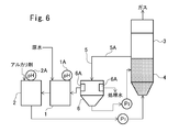
- FIG. 6 is a flowchart of the anaerobic processing apparatus of Patent Document 1.
- This anaerobic treatment apparatus treats water to be treated (raw water) in the acid generation tank 1, then feeds it to the pH adjustment tank 2 to adjust the pH, and the pH-adjusted water is supplied to the fluid abiotic carrier 4 by the pump P 1.
- the water is treated by passing water upward in the reaction tank 3 filled with the above.
- the outlet side of the bubble separation pipe 5 opens into the treated water tank 6 whose bottom surface is inclined.
- 6A is a screen.
- the treated water containing the floating carrier flowing out from the reaction tank 3 flows down the bubble separation pipe 5 through the outflow pipe 5A, and is then fed to the treated water tank 6 having the screen 6A.
- the carrier in the treated water that has flowed out of the reaction tank 3 recovers its sedimentation by separating and removing bubbles while flowing down the bubble separation pipe 5, and quickly settles in the treated water tank 6.
- a of the treated water tank 6 is discharged out of the system as treated water, and the remainder is circulated to the acid generation tank 1. Meanwhile, the carrier of sediment in the process water tank 6 is returned to the reaction vessel 4 with the treated water by a pump P 2.
- 1A and 2A are pH meters.
- Patent Documents 3 and 4 describe that in an anaerobic reaction tank, a carrier separation screen is installed in the treated water discharge section at the top of the tank.
- An object of the present invention is to reduce the number of equipment and the installation space in an anaerobic treatment apparatus having a function for preventing the outflow of a carrier from an anaerobic treatment tank filled with a fluid carrier. .
- Another object of the present invention is to provide an anaerobic treatment method using this anaerobic treatment apparatus.
- the anaerobic treatment apparatus of the present invention treats water to be treated by passing water to be treated into a tank filled with a fluid nonbiological carrier under anaerobic conditions to form a biofilm on the surface of the nonbiological carrier.
- the settling speed of the carrier is 200 to 500 m / hr, and the flow regulating plate is separated from the biological treatment chamber and the carrier-containing water receiving chamber having a treated water outlet in the tank.
- a pair of current plates are arranged at an interval so as to form a carrier drawing channel between them, and the carrier drawing channel has an inclination
- the upper end side of the carrier intake channel is connected to the biological treatment chamber, and the lower end side is arranged to be connected to the carrier-containing water receiving chamber, and the carrier-containing water in the biological treatment chamber passes through the carrier intake channel from the upper side to the lower side. To pass through to the side and flow into the carrier-containing water receiving chamber. And butterflies.
- the channel width of the carrier drawing channel is 20 to 50 times the average particle size of the carrier, and the channel length of the carrier drawing channel is the average of the carrier. 50 to 100 times the particle size.
- a carrier return channel is provided for returning the carrier that has settled in the carrier-containing water receiving chamber to the biological treatment chamber.
- the anaerobic treatment method of the present invention treats organic wastewater using the anaerobic treatment apparatus of the present invention.
- the current plate is arranged in the vertical direction (including the oblique direction) in the tank, and the carrier drawing channel through which the carrier can pass downward is formed along the current plate.
- a treated water discharge part is provided above the outlet of the carrier drawing channel, a carrier separation screen is provided in the treated water discharge part, and the sedimentation speed of the carrier is 200 to 500 m / h. Therefore, the carrier settles in the carrier-containing water receiving chamber, hardly reaches the treated water discharge part, and the carrier is prevented from flowing out.
- the following effects are produced. (1) Installation of the carrier circulating water tank and the treated water tank is unnecessary, and the installation area can be reduced. (2) The gas treatment incidental facilities set in the carrier circulation water tank are not required. (3) Since a carrier to which bubbles do not adhere or a carrier to which bubbles slightly adhere but sediments passes through the carrier drawing channel, blockage of the screen due to floating of the carrier is difficult to occur. (4) Since a carrier to which bubbles do not adhere or a carrier to which bubbles slightly adhere but sediments passes through the carrier drawing channel, the carrier settled in the carrier-containing water receiving chamber is returned to the tank. When the carrier return channel is provided, the carrier is smoothly returned from the carrier return channel to the biological treatment chamber without floating in the carrier-containing water receiving chamber.
- FIG. 1a is a longitudinal sectional view of an anaerobic treatment apparatus according to an embodiment.
- 1b is a cross-sectional view taken along the line BB of FIG. 1a. It is a longitudinal cross-sectional view of the anaerobic processing apparatus which concerns on embodiment. It is a longitudinal cross-sectional view of the anaerobic processing apparatus which concerns on embodiment. It is a longitudinal cross-sectional view of the anaerobic processing apparatus which concerns on embodiment. It is a longitudinal cross-sectional view of the anaerobic processing apparatus which concerns on embodiment. It is a flowchart of the conventional anaerobic processing apparatus.
- the anaerobic treatment apparatus 10 of FIGS. 1a and 1b introduces raw water from the bottom (may be a lower part) of a tank body 11 constituting a reaction tank, and a fluid carrier that is filled in the tank body 11 and It is comprised so that it may be made to contact and anaerobic biological treatment may be performed.
- the treated water passes through the carrier separation screen 12 provided at the upper part of the side surface in the tank body 11 and is taken out via the treated water take-out pipe 13.
- Rectifying plates 20 and 30 are provided so as to surround the screen 12.
- the tank body 11 includes a carrier-containing water receiving chamber B surrounded by a lower part of the rectifying plate 20 (below the part forming the carrier drawing channel) and the rectifying plate 30, and a biological treatment chamber A in which the carrier flows. It is partitioned. Both sides of the current plates 20 and 30 are connected to the tank body 11.
- the rectifying plate 30 is provided in the vertical direction (vertical direction in this embodiment), and the upper end of the rectifying plate 30 protrudes above the water surface WL in the tank body 11.
- the lower end of the rectifying plate 30 is located about 50 to 500 mm below the upper end of the rectifying plate 20 and about 50 to 500 mm below the lower end of the carrier separation screen.
- the rectifying plate 20 faces the rectifying plate 30, is connected to the first vertical plate portion 20 a located closer to the biological treatment chamber A than the rectifying plate 30, and the lower end of the first vertical plate portion 20 a.
- An inclined portion 20b extending in a downward gradient toward the vicinity of the wall surface of the tank body 11 through the side, and a second vertical plate portion 20c extending downward from the lower end of the inclined portion 20b.
- a region sandwiched between the rectifying plate 20 and the rectifying plate 30 is a carrier drawing channel 14.
- a carrier return flow path 15 is formed between the second vertical plate portion 20 c and the inner wall surface of the tank body 11.
- a discharge part for biological treatment gas such as methane is provided at the top of the tank body 11.
- the carrier-containing water including the carrier rolled up in the biological treatment chamber A flows into the carrier-containing water receiving chamber B through the carrier drawing channel 14. .
- the carrier in the carrier-containing water is solid-liquid separated into the carrier and the treated water while the carrier-containing water stays in the carrier-containing water receiving chamber B, and flows down along the inclined portion 20b. Returned to processing chamber A.
- the carrier drawing channel 14 has a channel width (horizontal distance between the first vertical plate portion 20a and the rectifying plate 30) that does not hinder the passage of the carrier, and the carrier to which bubbles are attached is difficult to pass. It is preferable to have a path length (a vertical distance from the upper end of the first vertical plate portion 20a to the lower end of the rectifying plate 30).
- the channel width of the carrier drawing channel is preferably about 25 to 50 times and the channel length is about 50 to 100 times the average particle size of the carrier.
- the channel width is 25 to 250 mm.
- the channel length is preferably about 50 to 500 mm.
- the carrier return channel 15 has a channel width (interval between the second vertical plate portion 21b and the inner wall surface of the tank body 11) that does not hinder the passage of the carrier and smoothly returns the carrier into the tank. It is preferable that the flow path length is such that it is not affected by the convection of the liquid in the tank (does not reverse flow).
- the average channel width of the carrier return channel is preferably about 25 to 50 times and the channel length is about 50 to 100 times the average particle size of the carrier.
- the channel width is 25
- the flow path length is preferably about 50 to 500 mm.
- the angles ⁇ 1 and ⁇ 2 with respect to the horizontal direction of the carrier pull-in channel 14 and the carrier return channel 15 may be arbitrary angles of 45 ° to 90 °.
- the angle ⁇ 3 with respect to the horizontal direction of the inclined portion 20b may be an arbitrary angle of 30 to 60 ° (however, ⁇ 1 and ⁇ 2 are larger than ⁇ 3 ).
- the carrier return flow path 15 may be provided with a return promotion means for ejecting water downward from the nozzle to form a water flow in the return direction (downward direction).
- the water to be ejected may be treated water of the treatment device or in-tank water.
- the carrier separation screen 12 Since the carrier separation screen 12 is disposed so as to be immersed in water and there is no concern about corrosion, a wedge wire screen made of SUS can be used as the carrier separation screen 12. However, the upper part of the carrier separation screen 12 may be positioned above the water surface WL.
- the upper part of the carrier-containing water receiving chamber B is opened to communicate with the biological treatment chamber A, but the upper part of the carrier-containing water receiving chamber B may be closed.
- the upper part of the current plate 30 is extended to the upper end of the tank body so that the gas phase region of the biological treatment chamber A and the gas phase region of the carrier-containing water receiving chamber B are completely partitioned. Also good.
- the carrier separation screen is used as the treated water discharge part, but a trough may be used when the carrier is sufficiently prevented from floating in the carrier-containing water receiving chamber B.
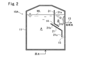
- rectifying plates 21 and 31 are installed instead of the rectifying plates 20 and 30.
- the rectifying plate 31 includes a vertical plate portion 31a having the same shape as that of the rectifying plate 30, and an inclined portion 31b that is connected to the lower end of the vertical plate portion 31a and extends substantially parallel to an inclined portion 21b of the rectifying plate 21 described later.
- the rectifying plate 21 has a configuration in which the first vertical plate portion 20a is omitted from the rectifying plate 20, and has a configuration including an inclined portion 21b and a second vertical plate portion 21c. A region sandwiched between the inclined portion 21b and the inclined portion 31b is the carrier drawing channel 14.
- the screen 12 is disposed at the upper center of the tank body 11. Further, instead of the rectifying plates 20 and 30, rectifying plates 22 and 32 are installed.
- the rectifying plate 32 has a cylindrical shape (cylindrical shape or rectangular tube shape) surrounding the carrier-containing water receiving chamber B around the screen 12, and the cylindrical axis direction is the vertical direction. The upper part of the current plate 32 protrudes above the water surface WL, and the lower part is submerged in water.
- the rectifying plate 22 includes a first cylindrical portion 22a that surrounds the outer periphery of the lower portion of the rectifying plate 32, a tapered portion 22b that is continuous with the lower end of the first cylindrical portion 22a and is inclined so as to be lower toward the center side, and the tapered portion
- the second cylindrical portion 22c is connected to the lower end of the 22b and extends downward.
- the first cylindrical portion 22a is submerged in water as a whole, and the upper end thereof is also positioned below the water surface WL.
- a region sandwiched between the first cylindrical portion 22 a and the rectifying plate 32 is the carrier drawing channel 14.
- the inside of the second cylinder portion 22c is a carrier return channel 15.
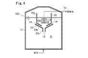
- the rectifying plate 33 is connected to the cylindrical portion 33a having the same configuration as that of the rectifying plate 32, is connected to the lower end of the cylindrical portion 33a, has a downward slope toward the center side, and a tapered portion 23b of the rectifying plate 23 to be described later. It has the taper part 33b which is parallel.
- the rectifying plate 23 has a configuration in which the first cylindrical portion 22a is omitted from the rectifying plate 22, and includes a tapered portion 23b and a second cylindrical portion 23c. A region sandwiched between the taper portion 23 b and the taper portion 33 b of the rectifying plate 33 is the carrier drawing channel 14.
- the tank bodies 11 of the above-described anaerobic treatment apparatuses 10 to 10C are all cylindrical and do not have a portion projecting outward from the side, but may include a portion projecting partially outward from the side. Good.
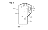
- FIG. 5 An example is shown in FIG. In the anaerobic treatment apparatus 10D of FIG. 5, an overhanging portion 17 that projects outward is provided in a part of the upper side of the tank body 11, and the inside of the overhanging portion 17 is the carrier-containing water receiving chamber B. It has become. A bottom surface 17t of the overhang portion 17 has a downward slope toward the biological treatment chamber A. A screen 12 is disposed in the carrier-containing water receiving chamber B.
- Rectifying plates 24 and 34 made of vertical plates are provided so as to partition the carrier-containing water receiving chamber B and the biological treatment chamber A, respectively. Both sides of the current plates 24 and 34 are connected to the tank body 11. The upper end of the rectifying plate 34 protrudes above the water surface WL. There is a gap between the lower end of the current plate 34 and the bottom surface 17t of the overhang portion 17.
- the rectifying plate 24 is located closer to the biological treatment chamber A than the rectifying plate 34.
- the rectifying plate 24 is located above the tank body side wall lower portion 11s on the overhanging portion 17 side.
- the upper end of the rectifying plate 24 is located above the lower end of the rectifying plate 34, and the space between the rectifying plates 24 and 34 is the carrier drawing channel 14.
- the lower end of the rectifying plate 24 is positioned lower than the lower end of the rectifying plate 34. Further, there is a gap between the lower end of the rectifying plate 24 and the bottom surface 17 t of the overhanging portion 17, and the carrier return channel 15 is formed between the two.
- the angle of the bottom surface 17t with respect to the horizontal direction may be an arbitrary angle of 45 to 60 °.
- the preferred values of the channel width and the channel length of the carrier drawing channel 14 and the carrier return channel 15 are the same as those of the anaerobic treatment device 10 of FIG. .
- the preferred value of the channel length of the carrier drawing channel 14 of FIG. 5 is the same as that of the anaerobic treatment apparatus 10 of FIG.
- the same effects as the anaerobic treatment apparatus 10 can be obtained by the anaerobic treatment apparatuses 10A to 10D shown in FIGS.
- the sedimentation rate and size of the carrier represent the sedimentation rate and size of the carrier to which no microorganisms or bubbles are attached.
- the fluid non-biological carrier used in the present invention has a sedimentation speed of 200 to 500 m / hr. If the sedimentation rate of the carrier is too small, the carrier is likely to float due to water flow or generated gas. Conversely, if the sedimentation rate of the carrier is too large, the contact efficiency with the water to be treated is deteriorated, and sufficient treatment efficiency cannot be obtained, or Detrimental effects such as accumulation of solid matter in the deposited layer of the carrier and blockage of the flow path are likely to occur.
- the sedimentation speed of the carrier is the amount of sedimentation by submerging the carrier in water (fresh water such as tap water), taking it into a graduated cylinder in water (fresh water such as tap water) It is a value obtained by measuring the distance. In the present invention, 10 to 20 carriers are measured, and the average value is taken as the sedimentation velocity.
- the carrier used in the present invention preferably has a size (average value) of 1.0 to 5.0 mm, particularly 2.5 to 4.0 mm.
- the size of the carrier is usually referred to as “particle size”.
- a rectangular parallelepiped carrier represents the length of the long side
- a cubic carrier represents the length of one side.
- a cylindrical carrier it represents the larger one of the diameter and the height of the cylinder.
- a carrier having an irregular shape other than these shapes when the carrier is sandwiched between two parallel plates, it represents the interval between the plates where the interval between the plates is the largest.
- the carrier used in the present invention is not particularly limited as long as the sedimentation rate satisfies the above range, and the constituent material of the carrier is not particularly limited.
- the water to be treated in the present invention may be any liquid containing an organic substance that can be treated by anaerobic treatment by contacting with anaerobic microorganisms, and the composition and concentration are not particularly limited.
- the COD concentration of the water to be treated is not particularly limited, but as described above, the anaerobic treatment using a carrier is a low-concentration wastewater that is difficult to apply to treatment using granules such as the UASB method and the EGSB method. since exhibits a particularly excellent effect in the treatment, as the water to be treated in the present invention, COD Cr concentration of 2000 mg / L or less, is effective in low concentration waste water treatment, for example, 500 ⁇ 2000mg / L.
- Such wastewater includes, but is not limited to, manufacturing wastewater from food factories, organic wastewater from chemical factories, general sewage, and the like.
Landscapes
- Life Sciences & Earth Sciences (AREA)
- Microbiology (AREA)
- Biodiversity & Conservation Biology (AREA)
- Hydrology & Water Resources (AREA)
- Engineering & Computer Science (AREA)
- Environmental & Geological Engineering (AREA)
- Water Supply & Treatment (AREA)
- Chemical & Material Sciences (AREA)
- Organic Chemistry (AREA)
- Purification Treatments By Anaerobic Or Anaerobic And Aerobic Bacteria Or Animals (AREA)
- Biological Treatment Of Waste Water (AREA)
Abstract
流動性の担体を充填した嫌気性処理槽からの担体の流出を防ぐための機能を備えた嫌気性処理装置において、機器点数の削減と設置スペースの低減を図る。嫌気性処理装置10内に流動性を有した担体が充填されている。原水は底部から槽内に流入し、生物処理室A内で処理された後、一部の担体を伴って担体引込流路14を通って担体含有水受入室B内に流入する。処理水はスクリーン12を通って取り出される。担体は受入室B内を沈降し、担体戻し流路15から生物処理室Aに戻される。
Description
本発明は、反応槽内に流動性を持つ担体を充填し、該担体の表面に生物膜を形成させて嫌気条件下で被処理水を通水して処理する嫌気性処理装置及び嫌気性処理方法に関する。
有機性排水の嫌気性処理方法として、反応槽内に高密度で沈降性の大きいグラニュール汚泥を形成し、溶解性BODを含む有機性排水を上向流通水して、スラッジブランケットを形成した状態で接触させて高負荷高速処理を行うUASB(Upflow Anaerobic Sludge Blanket:上向流嫌気性スラッジブランケット)法が採用されている。この方法は、消化速度の遅い固形有機物を分離して別途処理し、消化速度の速い溶解性有機物のみを、嫌気性微生物密度の高いグラニュール汚泥を用いる嫌気性処理によって高負荷で高速処理する方法である。また、このUASB法を発展させたものとして、高さの高い反応槽を用いてさらに高流速で通水し、スラッジブランケットを高展開率で展開して、さらに高負荷で嫌気性処理を行うEGSB(Expanded Granule Sludge Blanket)法も行われている。
UASB法、EGSB法などのグラニュール汚泥を用いる嫌気性処理は、嫌気性微生物を含む汚泥をグラニュール状に維持、増殖させて処理する方法である。この方法は担体に汚泥を保持する固定床や流動床による処理と比較して高い汚泥保持濃度を達成することができるため、高負荷運転が可能であり、また、既に稼働中の処理系から余剰汚泥を調達することにより短期間で立上げが可能であり、最も効率的な嫌気性処理法として一般にも認識されている。
しかし、これらグラニュール汚泥を用いる方法は、排水のCOD濃度が高い(CODCr濃度として概ね2000mg/L以上)場合には非常に効率が高いが、COD濃度が低い場合(CODCr濃度として概ね2000mg/L以下)には反応槽に多くの水量を流す必要が生じ、グラニュールが流出してしまう危険性が増し、安定した性能を発揮し得ない傾向がある。
排水の種類によってはグラニュールが形成されにくい排水が存在し、初期に投入したグラニュールが徐々に解体してしまい、運転不能となる場合があることも知られている。
これに対し、流動性の非生物担体を用いる方法では、スクリーン等の機械的な方法で反応槽からの担体の流出を防ぐことができ、また、担体表面は常に微生物の生育場所として確保できるため、低濃度のCOD排水やグラニュールが解体してしまうような排水に対しても適用できるという利点がある。
非生物担体であれば比重や大きさの設計の自由度が高く、グラニュールと比較すると沈降速度を非常に大きく設定することも可能である。沈降速度の大きな担体を利用すると、グラニュール法において必要とされる気液固分離のための機構(GSS:Gas Solid Separator)が不要となり、反応槽の有効体積を大きくするとともに建設コストも大幅に抑えることができるという利点もある。
しかしながら、流動性の非生物担体を用いる方法では、担体に微生物が付着して担体の表面に生物膜が形成され、生物膜内部でガスが発生する反応が進行し、発生したガスが担体に付着する結果、担体の見かけ比重が小さくなって担体が反応槽内で浮上し、処理水と共に流出してしまうという問題がある。このような問題は、比重が大きく、沈降速度の大きい担体を用いることにより軽減することは可能であるが、比重が過度に大きく、沈降速度が過度に大きい担体では、被処理水との接触効率が悪く十分な処理効率が得られず、また、沈降した担体の堆積層に固形物が蓄積して流路が閉塞するといった問題があり、一方で、このような問題のない担体を用いた場合、上述の発生ガスによる担体の浮上、流出を避けることは困難である。
特許文献1,2では、浮上した担体を反応槽から抜き出し、抜き出した担体を反応槽外部に引き回した循環配管で再度反応槽に戻すようにした装置が提案されている。図6は、特許文献1の嫌気性処理装置のフロー図である。
この嫌気性処理装置は、被処理水(原水)を酸生成槽1で処理した後、pH調整槽2に送給してpH調整し、pH調整水をポンプP1により流動性非生物担体4を充填した反応槽3に上向流で通水して処理するものである。反応槽3の上部側壁には、反応槽3内の処理水を浮上した担体と共に抜き出す流出配管5Aが設けられ、この流出配管5Aに、50cm以上の落差を有する気泡分離配管5が鉛直方向に連結されている。
気泡分離配管5の流出口側は、底面が傾斜面とされた処理水槽6内に開口する。6Aはスクリーンである。反応槽3から流出する浮上担体を含む処理水は、流出配管5Aを経て気泡分離配管5を流下した後、スクリーン6Aを有する処理水槽6に送給される。反応槽3から流出した処理水中の担体は、気泡分離配管5を流下する間に気泡が分離除去されることにより沈降性が回復し、処理水槽6内で速やかに沈降する。処理水槽6のスクリーン6Aの透過水の一部は、処理水として系外へ排出され、残部は酸生成槽1に循環される。一方、処理水槽6で沈降した担体は、ポンプP2により処理水と共に反応槽4に返送される。1A,2AはpH計である。
上記の嫌気性処理装置では、担体循環のために処理水槽6を別途設ける必要がある上に、担体から分離された気泡(メタンガス)を処理するための付帯設備も別途必要になるため、システムの構成要素が多くなってしまい、また設置面積が大きくなってしまうという問題があった。
特許文献3,4には、嫌気性反応槽において、槽上部の処理水排出部に担体分離スクリーンを設置することが記載されている。
しかしながら、スクリーンは目詰りし易いので、頻繁にメンテナンスする必要がある。
本発明は、流動性の担体を充填した嫌気性処理槽からの担体の流出を防ぐための機能を備えた嫌気性処理装置において、機器点数の削減と設置スペースの低減を図ることを目的とする。
また、本発明は、この嫌気性処理装置を用いた嫌気性処理方法を提供することを目的とする。
本発明の嫌気性処理装置は、流動性の非生物担体を充填した槽内に嫌気条件下で被処理水を通水し、該非生物担体の表面に生物膜を形成させて被処理水を処理する嫌気性処理装置において、該担体の沈降速度が200~500m/hrであり、該槽内に、生物処理室と、処理水取出部を有した担体含有水受入室とを隔てるように整流板が配置され、該整流板として、1対の整流板が、両者間に担体引込流路が形成されるように間隔をあけて配置されており、該担体引込流路は傾斜を有し、該担体引込流路の上端側は該生物処理室に連なり、下端側は該担体含有水受入室に連なるように配置され、前記生物処理室内の担体含有水が該担体引込流路を上部側から下部側に通り抜けて前記担体含有水受入室に流入するように構成されていることを特徴とする。
本発明の一態様では、前記担体引込流路の流路幅(整流板同士の間隔)は、担体の平均粒径の20~50倍であり、担体引込流路の流路長は担体の平均粒径の50~100倍である。
本発明の一態様では、前記担体含有水受入室内で沈降した担体を前記生物処理室に戻す担体戻し流路が設けられている。
本発明の嫌気性処理方法は、本発明の嫌気性処理装置を用いて有機性排水を処理する。
本発明の嫌気性処理装置にあっては、槽内に整流板を上下方向(斜め方向を含む。)に配置し、担体が下方向に通過できる担体引込流路を該整流板に沿って形成し、担体含有水受入室に、該担体引込流路出口より上位に処理水排出部を設け、処理水排出部に担体分離スクリーンを設け、担体の沈降速度を200~500m/hとしている。そのため、担体は該担体含有水受入室内において沈降し、処理水排出部には殆ど到達せず、担体の流出が防止される。
従って、本発明によると、次の効果が奏される。
(1)担体循環水槽および処理水槽の設置が不要となり設置面積を低減できる。
(2)担体循環水槽に設定していたガス処理の付帯設備が不要となる。
(3)気泡が付着していない担体や、わずかに気泡が付着するが沈降性のある担体が担体引込流路を通過するので、担体の浮上によるスクリーン閉塞が発生しづらい。
(4)気泡が付着していない担体や、わずかに気泡が付着するが沈降性のある担体が担体引込流路を通過するので、担体含有水受入室で沈降した担体を槽内に戻すための担体戻し流路を設けた場合には、担体は、担体含有水受入室内で浮上することなく担体戻し流路からスムーズに生物処理室に返送される。
(1)担体循環水槽および処理水槽の設置が不要となり設置面積を低減できる。
(2)担体循環水槽に設定していたガス処理の付帯設備が不要となる。
(3)気泡が付着していない担体や、わずかに気泡が付着するが沈降性のある担体が担体引込流路を通過するので、担体の浮上によるスクリーン閉塞が発生しづらい。
(4)気泡が付着していない担体や、わずかに気泡が付着するが沈降性のある担体が担体引込流路を通過するので、担体含有水受入室で沈降した担体を槽内に戻すための担体戻し流路を設けた場合には、担体は、担体含有水受入室内で浮上することなく担体戻し流路からスムーズに生物処理室に返送される。
以下、図1a~5を参照して本発明の嫌気性処理装置の一例について説明する。
図1a,1bの嫌気性処理装置10は、反応槽を構成する槽体11の底部(下部であってもよい。)から原水を導入し、槽体11内に充填されている流動性担体と接触させて嫌気性生物処理を行うよう構成されている。処理水は、槽体11内の側面の上部に設けられた担体分離スクリーン12を透過し、処理水取出管13を介して取り出される。
このスクリーン12を囲むようにして整流板20,30が設けられている。槽体11内は、該整流板20の下部(担体引込流路を形成する部位より下部)及び整流板30で囲まれた担体含有水受入室Bと、担体が流動する生物処理室Aとに区画されている。整流板20,30の両側辺部は槽体11に連なっている。
整流板30は、上下方向(この実施の形態では鉛直方向)に設けられており、その上端は槽体11内の水面WLよりも上方に突出している。整流板30の下端は整流板20の上端より50~500mm程度下位、かつ担体分離スクリーンの下端より50~500mm程度下位に位置している。
整流板20は、整流板30に対面し、整流板30よりも生物処理室A側に位置する第1縦板部20aと、該第1縦板部20aの下端に連なり、整流板30の下側を通って槽体11の壁面近傍に向って下り勾配にて延在した傾斜部20bと、該傾斜部20bの下端に連なり、下方に延在した第2縦板部20cとを有している。整流板20と整流板30とで挟まれた領域が担体引込流路14となっている。第2縦板部20cと槽体11の内壁面との間が担体戻し流路15となっている。
図示は省略するが、槽体11の頂部にはメタン等の生物処理ガスの排出部が設けられている。
このように構成された嫌気性処理装置10にあっては、生物処理室A内で巻き上がった担体を含む担体含有水が担体引込流路14を通って担体含有水受入室B内に流入する。担体含有水中の担体は、担体含有水が担体含有水受入室B内に滞留する間に担体と処理水とに固液分離され、傾斜部20bに沿って流れ下り、担体戻し流路15から生物処理室Aに返送される。
担体引込流路14は、担体通過の妨げとならない流路幅(第1縦板部20aと整流板30との間の水平方向距離)を有し、かつ気泡が付着した担体が通過しづらい流路長(第1縦板部20aの上端から整流板30の下端までの鉛直方向の距離)を有することが好ましい。具体的には担体の平均粒径に対し、担体引込流路の流路幅は25~50倍程度、流路長は50~100倍程度とするのが好ましく、例えば流路幅は25~250mm程度、流路長は50~500mm程度とするのが好ましい。
同様に、担体戻し流路15は、担体の通過の妨げとならず担体がスムーズに槽内に返送される程度の流路幅(第2縦板部21bと槽体11の内壁面との間隔)であり、かつ槽内液の対流の影響を受けない(逆流しない)程度の流路長さであることが好ましい。具体的には担体の平均粒径に対し、担体戻し流路の平均流路幅は25~50倍程度、流路長は50~100倍程度とするのが好ましく、例えば、流路幅は25~250mm程度、流路長は50~500mm程度とするのが好ましい。
担体引込流路14や担体戻し流路15の水平方向に対する角度θ1,θ2は45°~90°の任意の角度でよい。傾斜部20bの水平方向に対する角度θ3は30~60°の任意の角度でよい(ただし、θ1,θ2はθ3より大きい)。
担体戻し流路15に、ノズルから水を下方向きに噴出させて返送方向(下向き方向)の水流を形成する返送促進手段を設けてもよい。噴出させる水は、該処理装置の処理水であってもよく、槽内水であってもよい。
担体分離スクリーン12は水中に没するように配置されており、腐食の心配がないので、担体分離スクリーン12としてはSUS製のウェッジワイヤースクリーンを用いることができる。ただし、担体分離スクリーン12の上部が水面WLよりも上方に位置するようにしてもよい。
本実施形態では、担体含有水受入室Bの上部は開放して生物処理室Aと連通しているが、担体含有水受入室Bの上部を閉鎖してもよい。この場合、整流板30の上部を槽体の上端まで延在させることで、生物処理室Aの気相領域と担体含有水受入室Bの気相領域とを完全に区画するように構成してもよい。
本実施形態では、処理水排出部として担体分離スクリーンを用いたが、担体含有水受入室B内で十分に担体の浮上が抑制される条件のときはトラフを用いてもよい。
本処理装置を用いて嫌気性生物処理を行うと、生物処理により発生したガスが担体に付着して生物処理室内で浮上するが、生物処理室の上部で気泡の殆どが担体から分離し、わずかに気泡が付着したまま沈降する担体の一部が担体引込流路に引き込まれ、担体引込流路を通過する間にさらに担体から気泡が分離して担体含有水受入室に流入する。このとき、担体含有水受入室に流入する担体には殆ど気泡が付着しておらず、十分に高い沈降速度となるので、担体が槽外に流出することがなく、また担体含有水受入室内は生物処理室内の対流から隔離されているので、担体引込流路の下端より高い位置にある担体分離スクリーンに担体が目詰りするリスクも低減される。
図2の嫌気性処理装置10Aでは、整流板20,30の代わりに整流板21,31が設置されている。整流板31は、前記整流板30と同様形状の縦板部31aと、該縦板部31aの下端に連なり、後述の整流板21の傾斜部21bと略平行に延在する傾斜部31bとを有する。整流板21は、前記整流板20から第1縦板部20aを省略した構成のものであり、傾斜部21bと第2縦板部21cとを備えた構成を有している。傾斜部21bと傾斜部31bとで挟まれた領域が担体引込流路14となっている。
この嫌気性処理装置10Aのその他の構成は嫌気性処理装置10と同一であり、同一符号は同一部分を示している。
図3の嫌気性処理装置10Bでは、スクリーン12が槽体11の中央上部に配置されている。また、整流板20,30の代わりに整流板22,32が設置されている。整流板32は、スクリーン12周囲の担体含有水受入室Bを取り囲む筒状(円筒状又は角筒状)であり、筒軸心方向を鉛直方向としている。整流板32の上部は水面WLよりも上方に突出しており、下部は水中に没している。
整流板22は、整流板32の下部の外周を取り囲む第1筒部22aと、該第1筒部22aの下端に連なり、中央側ほど下位となるように傾斜したテーパ部22bと、該テーパ部22bの下端に連なり、下方に延在した第2筒部22cとを有する。第1筒部22aは全体として水中に没しており、その上端も水面WLより下位に位置している。第1筒部22aと整流板32とで挟まれた領域が担体引込流路14となっている。第2筒部22c内が担体戻し流路15となっている。
この嫌気性処理装置10Bのその他の構成は嫌気性処理装置10と同一であり、同一符号は同一部分を示している。
図4の嫌気性処理装置10Cは、整流板22,32の代わりに整流板23,33を設置している。整流板33は、整流板32と同一構成の筒部33aと、該筒部33aの下端に連なり、中央側に向って下り勾配となっており、かつ、後述の整流板23のテーパ部23bと平行となっているテーパ部33bを有している。整流板23は、整流板22から第1筒部22aを省略した構成のものであり、テーパ部23bと第2筒部23cとを有する。このテーパ部23bと、整流板33のテーパ部33bとで挟まれた領域が担体引込流路14となっている。
嫌気性処理装置10Cのその他の構成は嫌気性処理装置10Bと同一であり、同一符号は同一部分を示している。
上記の嫌気性処理装置10~10Cの槽体11は、いずれも筒状であり、側外方に張り出す部分を有していないが、部分的に側外方に張り出す部分を備えてもよい。
その一例を図5に示す。図5の嫌気性処理装置10Dでは、槽体11の側面上部の一部に、側外方に張り出す張出部17が設けられており、この張出部17内が担体含有水受入室Bとなっている。張出部17の底面17tは、生物処理室Aに向って下り勾配となっている。該担体含有水受入室B内にスクリーン12が配置されている。
担体含有水受入室Bと生物処理室Aとを区画するように、それぞれ縦板よりなる整流板24,34が設けられている。整流板24,34の両側辺部は槽体11に連なっている。整流板34の上端は水面WLよりも上方に突出している。整流板34の下端と張出部17の底面17tとの間に間隔があいている。整流板24は、整流板34よりも生物処理室A側に位置している。整流板24は、張出部17側の槽体側壁下部11sの上方に位置している。整流板24の上端は整流板34の下端よりも上方に位置しており、整流板24,34間が担体引込流路14となっている。整流板24の下端は整流板34の下端よりも下位に位置している。また、整流板24の下端と張出部17の底面17tとの間に間隔があいており、両者間が担体戻し流路15となっている。底面17tの水平方向に対する角度は45~60°の任意の角度でよい。
図2~4の嫌気性処理装置10A~10Cにおいても、担体引込流路14及び担体戻し流路15の流路幅、流路長の好適値は図1の嫌気性処理装置10と同じである。図5の担体引込流路14の流路長の好適値は図1の嫌気性処理装置10と同じである。図2~5の嫌気性処理装置10A~10Dによっても嫌気性処理装置10と同様の作用効果が得られる。
本発明で用いる流動性非生物担体について次に説明する。なお、以下の説明において、担体の沈降速度及び大きさとは、微生物や気泡が付着していない担体の沈降速度及び大きさを表す。
本発明で用いる流動性非生物担体は、沈降速度が200~500m/hrのものである。担体の沈降速度が小さすぎると、水流や発生ガスにより浮上し易く、逆に、担体の沈降速度が大きすぎると被処理水との接触効率が悪くなり、十分な処理効率が得られない、或いは担体の堆積層に固形物が蓄積して流路が閉塞するといった弊害が出やすくなる。
担体の沈降速度とは、担体を水(水道水等の清水)に浸して沈んだものを取り出し、これを水(水道水等の清水)に入れたメスシリンダーに投入し、単位時間当たりの沈降距離を測定して求められた値であり、本発明においては、10~20個の担体について測定を行い、その平均値を沈降速度とする。
担体の大きさが大き過ぎると反応槽体積当りの表面積が小さくなり、小さ過ぎると沈降速度が遅くなり、処理水との分離が困難になる。本発明で用いる担体は、大きさ(平均値)が1.0~5.0mm特に2.5~4.0mmであることが好ましい。
担体の大きさとは、通常「粒径」と称されるものであり、例えば直方体形状の担体であればその長辺の長さを表し、立方体形状の担体であればその一辺の長さを表し、円柱形状の担体であれば直径又は円柱の高さのうちいずれか大きい方を表す。また、これらの形状以外の異形形状の担体であれば、担体を2枚の平行な板で挟んだときに、この板の間隔が最も大きくなる部位の板の間隔を表す。
本発明で用いる担体は、その沈降速度が上記範囲を満たすものであればよく、担体の構成材料には特に制限はない。
本発明において処理対象となる被処理水は、嫌気性微生物と接触させて嫌気性処理を行うことにより処理可能な有機物を含む液であればよく、組成や濃度には特に制限は無い。
被処理水のCOD濃度としては特に制限はないが、担体を用いる嫌気性処理は、前述の如く、UASB法やEGSB法のようなグラニュールを用いた処理への適用が困難な低濃度排水の処理において特に優れた効果を発揮することから、本発明における被処理水としては、CODCr濃度が2000mg/L以下、例えば500~2000mg/Lの低濃度排水の処理に有効である。このような排水としては、食品工場等の製造廃水、化学工場等の有機性廃水、一般下水等が含まれるが、何らこれらに限定されるものではない。
本発明を特定の態様を用いて詳細に説明したが、本発明の意図と範囲を離れることなく様々な変更が可能であることは当業者に明らかである。
本出願は、2015年9月25日付で出願された日本特許出願2015-188554に基づいており、その全体が引用により援用される。
本出願は、2015年9月25日付で出願された日本特許出願2015-188554に基づいており、その全体が引用により援用される。
1 酸生成槽
2 pH調整槽
3 反応槽
4 流動性非生物担体
5 気泡分離配管
6 処理水槽
10,10A~10D 嫌気性処理装置
11 槽体
12 スクリーン
13 処理水取出管
14 担体引込流路
15 担体戻し流路
20~24,30~34 整流板
2 pH調整槽
3 反応槽
4 流動性非生物担体
5 気泡分離配管
6 処理水槽
10,10A~10D 嫌気性処理装置
11 槽体
12 スクリーン
13 処理水取出管
14 担体引込流路
15 担体戻し流路
20~24,30~34 整流板
Claims (4)
- 流動性の非生物担体を充填した槽内に嫌気条件下で被処理水を通水し、該非生物担体の表面に生物膜を形成させて被処理水を処理する嫌気性処理装置において、
該担体の沈降速度が200~500m/hrであり、
該槽内に、生物処理室と、処理水取出部を有した担体含有水受入室とを隔てるように整流板が配置され、
該整流板として、1対の整流板が、両者間に担体引込流路が形成されるように間隔をあけて配置されており、
該担体引込流路は傾斜を有し、該担体引込流路の上端側は該生物処理室に連なり、下端側は該担体含有水受入室に連なるように配置され、
前記生物処理室内の担体含有水が該担体引込流路を上部側から下部側に通り抜けて前記担体含有水受入室に流入するように構成されていることを特徴とする嫌気性処理装置。 - 請求項1において、前記担体引込流路の流路幅(整流板同士の間隔)は、担体の平均粒径の20~50倍であり、担体引込流路の流路長は担体の平均粒径の50~100倍であることを特徴とする嫌気性処理装置。
- 請求項1又は2において、前記担体含有水受入室内で沈降した担体を前記生物処理室に戻す担体戻し流路を備えたことを特徴とする嫌気性処理装置。
- 請求項1ないし3のいずれか1項に記載の嫌気性処理装置を用いて有機性排水を処理する嫌気性処理方法。
Applications Claiming Priority (2)
| Application Number | Priority Date | Filing Date | Title |
|---|---|---|---|
| JP2015-188554 | 2015-09-25 | ||
| JP2015188554A JP6048557B1 (ja) | 2015-09-25 | 2015-09-25 | 嫌気性処理装置および嫌気性処理方法 |
Publications (1)
| Publication Number | Publication Date |
|---|---|
| WO2017051560A1 true WO2017051560A1 (ja) | 2017-03-30 |
Family
ID=57572438
Family Applications (1)
| Application Number | Title | Priority Date | Filing Date |
|---|---|---|---|
| PCT/JP2016/062465 Ceased WO2017051560A1 (ja) | 2015-09-25 | 2016-04-20 | 嫌気性処理装置および嫌気性処理方法 |
Country Status (2)
| Country | Link |
|---|---|
| JP (1) | JP6048557B1 (ja) |
| WO (1) | WO2017051560A1 (ja) |
Citations (8)
| Publication number | Priority date | Publication date | Assignee | Title |
|---|---|---|---|---|
| JPS60235696A (ja) * | 1984-05-09 | 1985-11-22 | Nippon Beet Sugar Mfg Co Ltd | 嫌気性消化槽 |
| JPS62282691A (ja) * | 1986-06-02 | 1987-12-08 | Sanki Eng Co Ltd | 嫌気性生物反応装置に於ける沈降分離機構 |
| JPH05337490A (ja) * | 1992-06-03 | 1993-12-21 | Fuji Kasui Kogyo Kk | 液媒体中でガスを付着して浮遊する微細な固体の分離装置 |
| JP2001187394A (ja) * | 1999-12-28 | 2001-07-10 | Sumitomo Heavy Ind Ltd | 廃水処理装置 |
| JP2003311292A (ja) * | 2002-04-24 | 2003-11-05 | Kurita Water Ind Ltd | 嫌気性水処理装置 |
| WO2012070493A1 (ja) * | 2010-11-26 | 2012-05-31 | 栗田工業株式会社 | 嫌気性処理方法 |
| JP2012110820A (ja) * | 2010-11-24 | 2012-06-14 | Kurita Water Ind Ltd | 嫌気性処理方法及び装置 |
| JP2015077534A (ja) * | 2013-10-15 | 2015-04-23 | 栗田工業株式会社 | 嫌気性処理方法及び嫌気性処理装置 |
-
2015
- 2015-09-25 JP JP2015188554A patent/JP6048557B1/ja active Active
-
2016
- 2016-04-20 WO PCT/JP2016/062465 patent/WO2017051560A1/ja not_active Ceased
Patent Citations (8)
| Publication number | Priority date | Publication date | Assignee | Title |
|---|---|---|---|---|
| JPS60235696A (ja) * | 1984-05-09 | 1985-11-22 | Nippon Beet Sugar Mfg Co Ltd | 嫌気性消化槽 |
| JPS62282691A (ja) * | 1986-06-02 | 1987-12-08 | Sanki Eng Co Ltd | 嫌気性生物反応装置に於ける沈降分離機構 |
| JPH05337490A (ja) * | 1992-06-03 | 1993-12-21 | Fuji Kasui Kogyo Kk | 液媒体中でガスを付着して浮遊する微細な固体の分離装置 |
| JP2001187394A (ja) * | 1999-12-28 | 2001-07-10 | Sumitomo Heavy Ind Ltd | 廃水処理装置 |
| JP2003311292A (ja) * | 2002-04-24 | 2003-11-05 | Kurita Water Ind Ltd | 嫌気性水処理装置 |
| JP2012110820A (ja) * | 2010-11-24 | 2012-06-14 | Kurita Water Ind Ltd | 嫌気性処理方法及び装置 |
| WO2012070493A1 (ja) * | 2010-11-26 | 2012-05-31 | 栗田工業株式会社 | 嫌気性処理方法 |
| JP2015077534A (ja) * | 2013-10-15 | 2015-04-23 | 栗田工業株式会社 | 嫌気性処理方法及び嫌気性処理装置 |
Also Published As
| Publication number | Publication date |
|---|---|
| JP2017060926A (ja) | 2017-03-30 |
| JP6048557B1 (ja) | 2016-12-21 |
Similar Documents
| Publication | Publication Date | Title |
|---|---|---|
| CN102197001B (zh) | 沉降装置、包含沉降装置的净化器及厌氧或需氧净化废水的方法 | |
| US10421669B2 (en) | Dissolved air flotation device | |
| US8043506B2 (en) | Process and reactor for anaerobic waste water purification | |
| CN102036731B (zh) | 自行凝集功能的长方形沉淀系统 | |
| JP6104829B2 (ja) | 嫌気性水処理システム | |
| CN113694566B (zh) | 一种油田三相分离工艺及分离系统 | |
| RU2522105C2 (ru) | Реактор с восходящим потоком и с управляемой рециркуляцией биомассы | |
| US20230150853A1 (en) | Anaerobic waste digestion system | |
| RU2430020C2 (ru) | Способ и реактор для анаэробной очистки сточных вод | |
| US7637379B2 (en) | Circular secondary clarifier for wastewater treatment and an improved solids-liquid separation process thereof | |
| KR102318251B1 (ko) | 축산폐수 처리시설의 침전여과장치 | |
| JP7423414B2 (ja) | 担体分離装置、担体分離装置の運転方法、多段担体分離装置、および嫌気性処理装置 | |
| JP6048557B1 (ja) | 嫌気性処理装置および嫌気性処理方法 | |
| CN100546692C (zh) | 含固体杂质的污水处理器 | |
| CN101979342A (zh) | 生物反应器 | |
| JP2008012466A (ja) | 水処理装置 | |
| US7332083B2 (en) | Process and device for biological treatment of a suspension in a bioreactor | |
| JPH10165980A (ja) | 有機性排水の嫌気性処理装置 | |
| KR101577063B1 (ko) | 폭기/침전 일체형 반응조를 구비한 하폐수 처리장치 | |
| WO2016158673A1 (ja) | 水処理装置および水処理方法 | |
| JP2017113662A (ja) | 嫌気性処理装置および嫌気性処理方法 | |
| JP7594992B2 (ja) | 担体分離装置、担体の分離方法および処理システム | |
| JPS6320197B2 (ja) | ||
| CN214399941U (zh) | 一种高效气浮沉淀装置 | |
| JP5899536B2 (ja) | 傾斜分離装置および当該傾斜分離装置を用いた分離方法 |
Legal Events
| Date | Code | Title | Description |
|---|---|---|---|
| 121 | Ep: the epo has been informed by wipo that ep was designated in this application |
Ref document number: 16848350 Country of ref document: EP Kind code of ref document: A1 |
|
| NENP | Non-entry into the national phase |
Ref country code: DE |
|
| 122 | Ep: pct application non-entry in european phase |
Ref document number: 16848350 Country of ref document: EP Kind code of ref document: A1 |