WO2017034169A1 - Method for transmitting synchronization signal using codebook in wireless communication system - Google Patents
Method for transmitting synchronization signal using codebook in wireless communication system Download PDFInfo
- Publication number
- WO2017034169A1 WO2017034169A1 PCT/KR2016/008367 KR2016008367W WO2017034169A1 WO 2017034169 A1 WO2017034169 A1 WO 2017034169A1 KR 2016008367 W KR2016008367 W KR 2016008367W WO 2017034169 A1 WO2017034169 A1 WO 2017034169A1
- Authority
- WO
- WIPO (PCT)
- Prior art keywords
- precoders
- precoder
- synchronization signal
- base station
- terminal
- Prior art date
Links
Images
Classifications
-
- H—ELECTRICITY
- H04—ELECTRIC COMMUNICATION TECHNIQUE
- H04B—TRANSMISSION
- H04B7/00—Radio transmission systems, i.e. using radiation field
- H04B7/02—Diversity systems; Multi-antenna system, i.e. transmission or reception using multiple antennas
- H04B7/04—Diversity systems; Multi-antenna system, i.e. transmission or reception using multiple antennas using two or more spaced independent antennas
- H04B7/06—Diversity systems; Multi-antenna system, i.e. transmission or reception using multiple antennas using two or more spaced independent antennas at the transmitting station
-
- Y—GENERAL TAGGING OF NEW TECHNOLOGICAL DEVELOPMENTS; GENERAL TAGGING OF CROSS-SECTIONAL TECHNOLOGIES SPANNING OVER SEVERAL SECTIONS OF THE IPC; TECHNICAL SUBJECTS COVERED BY FORMER USPC CROSS-REFERENCE ART COLLECTIONS [XRACs] AND DIGESTS
- Y02—TECHNOLOGIES OR APPLICATIONS FOR MITIGATION OR ADAPTATION AGAINST CLIMATE CHANGE
- Y02D—CLIMATE CHANGE MITIGATION TECHNOLOGIES IN INFORMATION AND COMMUNICATION TECHNOLOGIES [ICT], I.E. INFORMATION AND COMMUNICATION TECHNOLOGIES AIMING AT THE REDUCTION OF THEIR OWN ENERGY USE
- Y02D30/00—Reducing energy consumption in communication networks
- Y02D30/70—Reducing energy consumption in communication networks in wireless communication networks
Definitions
- the following description relates to a wireless communication system, and more particularly, to a synchronization signal transmission method and apparatus using a synchronization signal codebook in a WLAN system.
- Ultra-high frequency wireless communication systems using millimeter wave are configured such that the center frequency operates at a few GHz to several tens of GHz. Due to the characteristics of the center frequency, path loss may be prominent in the shadow area in the mmWave communication system. Considering that the synchronization signal should be stably transmitted to all terminals located within the coverage of the base station, the mmWave communication system designs and transmits the synchronization signal in consideration of the potential deep-null phenomenon that may occur due to the characteristics of the ultra-high frequency band described above. Should be.
- the present invention has been made to solve the above problems, an object of the present invention to improve the synchronization process between the base station and the terminal in the wireless communication system to improve the efficiency of the synchronization process.
- Another object of the present invention is to improve the precoder performance applied to a synchronization sequence by proposing a codebook for the transmission of the synchronization signal.
- Another object of the present invention is to minimize power loss while maintaining the performance of the synchronization signal transmission process.
- a synchronization signal transmission method including a codebook including second precoders defined as concatenation of a plurality of first precoders corresponding to each of a plurality of antenna subarrays. Acquiring a signal, and repeatedly transmitting a synchronization signal to the terminal by applying different second precoders selected from the codebook over a plurality of time intervals to the synchronization sequence, wherein the plurality of antenna subarrays are assigned to each terminal. Independently controlled by the corresponding first precoder to perform beamforming of the synchronization signal.
- One second precoder is defined as a concatenation of a plurality of weighted first precoders, and the weights may be different for each of the plurality of second precoders constituting the codebook.
- the weights applied to the plurality of first precoders may have the same magnitude and different phases.
- Each of the plurality of first precoders may be defined as a concatenation of third precoders constituting a narrower beam than the first precoder.
- the synchronization sequence may remain the same over a plurality of time intervals.
- Each of the plurality of antenna subarrays may correspond to an RF chain of a base station.
- the base station for solving the technical problem includes a transmitter, a receiver, and a processor operating in connection with the transmitter and the receiver, the processor, a plurality of first free corresponding to each of the plurality of antenna subarrays (antenna subarray) Acquiring a codebook consisting of second precoders defined by concatenation of coders, and applying different second precoders selected from the codebook to the synchronization sequence over a plurality of time intervals, thereby repeating the synchronization signal to the terminal.
- the plurality of antenna sub-arrays are controlled independently by each other by a first precoder corresponding to each other to perform beamforming of a synchronization signal.
- Another synchronization signal transmission method for solving the above technical problem comprises a second precoder defined by concatenation of a plurality of first precoders corresponding to each of a plurality of antenna subarrays. Obtaining a codebook, and applying a second precoder selected from the codebook to a synchronization sequence whose sign is changed every time interval, thereby repeatedly transmitting a synchronization signal to the terminal over a plurality of time intervals. And a plurality of antenna sub-arrays are independently controlled from each other by a first precoder corresponding to each other to perform beamforming of a synchronization signal.
- Another base station for solving the technical problem includes a transmitter, a receiver, and a processor operating in connection with the transmitter and the receiver, the processor comprising: a plurality of agents corresponding to each of the plurality of antenna subarrays; By obtaining a codebook consisting of second precoders defined by concatenation of one precoder, and applying any second precoder selected from the codebook to a synchronization sequence whose sign is changed every time interval, Repeatedly transmit the synchronization signal to the terminal over the time interval of, the plurality of antenna sub-arrays are controlled independently of each other by a first precoder corresponding to each, and performs beamforming of the synchronization signal.
- the synchronization process between the base station and the terminal in the wireless communication system is improved to enable an efficient synchronization process between the base station and the terminal.
- AAS Active Antenna System
- 1 is a diagram illustrating a Doppler spectrum.
- FIG. 2 is a diagram illustrating narrow beamforming according to the invention.
- 3 is a diagram illustrating Doppler spectra when narrow beamforming is performed.
- FIG. 4 is a diagram illustrating an example of a synchronization signal service zone of a base station.
- 5 is an example of a frame structure proposed in a communication environment using mmWave.
- OVSF Orthogonal Variable Spreading Factor
- FIG. 7 is a diagram illustrating an example of an arrangement of terminals.
- FIG. 8 is a diagram illustrating a synchronization signal transmission structure according to one embodiment.
- FIG 9 illustrates a synchronization signal repeatedly transmitted according to an embodiment.
- FIG. 10 illustrates a process of estimating sequence and timing by a terminal receiving a synchronization signal.
- FIG. 11 illustrates another embodiment of a process in which a terminal synchronizes timing by using a synchronization signal.
- FIG. 12 is a flowchart illustrating a synchronization signal transmission and reception method according to an embodiment.
- FIG. 13 is a view illustrating another embodiment related to a synchronization signal transmission / reception method.
- 14 to 17 are diagrams illustrating a synchronization signal transmission structure according to another embodiment.
- FIGS. 14 to 17 are flowchart illustrating a synchronization signal transmission and reception method according to FIGS. 14 to 17.
- 19 and 20 illustrate a structure of transmitting a synchronization signal and a beam scanning signal for explaining another proposed embodiment.
- 21 to 23 illustrate a structure of transmitting a synchronization signal and a beam scanning signal according to a proposed embodiment.
- 24 is a flowchart illustrating a synchronization process and a beam scanning process according to another embodiment of the present disclosure.
- 25 is a diagram for explaining a beam extension technique.
- AAS active antenna system
- 27 to 30 illustrate a synchronization signal and beam scanning signal transmission structure according to another embodiment of the present invention.
- 31 is a flowchart illustrating a synchronization process and a beam scanning process according to another embodiment of the present disclosure.
- 32 is a diagram illustrating a configuration of a terminal and a base station according to the proposed embodiment.
- each component or feature may be considered to be optional unless otherwise stated.
- Each component or feature may be embodied in a form that is not combined with other components or features.
- some of the components and / or features may be combined to form an embodiment of the present invention.
- the order of the operations described in the embodiments of the present invention may be changed. Some components or features of one embodiment may be included in another embodiment, or may be replaced with corresponding components or features of another embodiment.
- the base station is meant as a terminal node of a network that directly communicates with a mobile station.
- the specific operation described as performed by the base station in this document may be performed by an upper node of the base station in some cases.
- various operations performed for communication with a mobile station in a network consisting of a plurality of network nodes including a base station may be performed by the base station or network nodes other than the base station.
- the 'base station' may be replaced by terms such as a fixed station, a Node B, an eNode B (eNB), an advanced base station (ABS), or an access point.
- a 'mobile station (MS)' may be a user equipment (UE), a subscriber station (SS), a mobile subscriber station (MSS), a mobile terminal, an advanced mobile station (AMS), a terminal. (Terminal) or a station (STAtion, STA) and the like can be replaced.
- UE user equipment
- SS subscriber station
- MSS mobile subscriber station
- AMS advanced mobile station
- Terminal or a station (STAtion, STA) and the like can be replaced.
- the transmitting end refers to a fixed and / or mobile node that provides a data service or a voice service
- the receiving end refers to a fixed and / or mobile node that receives a data service or a voice service. Therefore, in uplink, a mobile station may be a transmitting end and a base station may be a receiving end. Similarly, in downlink, a mobile station may be a receiving end and a base station may be a transmitting end.
- the description that the device communicates with the 'cell' may mean that the device transmits and receives a signal with the base station of the cell. That is, a substantial target for the device to transmit and receive a signal may be a specific base station, but for convenience of description, it may be described as transmitting and receiving a signal with a cell formed by a specific base station.
- the description of 'macro cell' and / or 'small cell' may not only mean specific coverage, but also 'macro base station supporting macro cell' and / or 'small cell supporting small cell', respectively. It may mean 'base station'.
- Embodiments of the present invention may be supported by standard documents disclosed in at least one of the wireless access systems IEEE 802.xx system, 3GPP system, 3GPP LTE system and 3GPP2 system. That is, obvious steps or parts which are not described among the embodiments of the present invention may be described with reference to the above documents.
- the error value of the oscillator of the terminal and the base station is defined as a requirement, and is described as follows.
- the UE modulated carrier frequency shall be accurate to within ⁇ 0.1 PPM observed over a period of one time slot (0.5 ms) compared to the carrier frequency received from the E-UTRA Node B
- Frequency error is the measure of the difference between the actual BS transmit frequency and the assigned frequency.
- Table 1 BS class Accuracy Wide Area BS ⁇ 0.05 ppm Local Area BS ⁇ 0.1 ppm Home BS ⁇ 0.25 ppm
- the maximum difference of the oscillator between the base station and the terminal is ⁇ 0.1ppm, and when an error occurs in one direction, a maximum offset value of 0.2 ppm may occur.
- This offset value is multiplied by the center frequency and converted into Hz units for each center frequency.
- the CFO value is shown differently by subcarrier spacing, and in general, even if the CFO value is large, the effect of the OFDM system with a sufficiently large subcarrier spacing is relatively small. Therefore, the actual CFO value (absolute value) needs to be expressed as a relative value affecting the OFDM system, which is called a normalized CFO.
- the normalized CFO is expressed by dividing the CFO value by the subcarrier spacing. Table 2 below shows the CFO and normalized CFO for each center frequency and oscillator error value.
- a subcarrier spacing (15 kHz) is assumed for a center frequency of 2 GHz (for example, LTE Rel-8 / 9/10), and a subcarrier spacing of 104.25 kHz for a center frequency of 30 GHz or 60 GHz. This prevents performance degradation considering the Doppler effect for each center frequency.
- Table 2 above is a simple example and it is apparent that other subcarrier spacings may be used for the center frequency.
- Doppler dispersion causes dispersion in the frequency domain, resulting in distortion of the received signal at the receiver's point of view.
- Doppler dispersion It can be expressed as.
- v is the moving speed of the terminal
- ⁇ means the wavelength of the center frequency of the transmitted radio waves.
- ⁇ means the angle between the received radio wave and the moving direction of the terminal. The following description is based on the assumption that ⁇ is zero.
- the coherence time is in inverse proportion to the Doppler variance. If the coherence time is defined as a time interval in which the correlation value of the channel response in the time domain is 50% or more, It is expressed as In a wireless communication system, Equation 1 below is mainly used which represents a geometric mean between the equation for Doppler variance and the equation for coherence time.
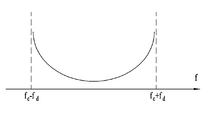
- 1 is a diagram illustrating a Doppler spectrum.
- the Doppler spectrum or Doppler power spectrum density, which represents a change in Doppler value according to the frequency change, may have various shapes according to a communication environment.
- a communication environment such as downtown
- the Doppler spectrum appears in the U-shape as shown in FIG. 1 shows the center frequency
- the maximum Doppler variance U-shaped Doppler spectra are shown.
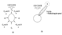
- FIG. 2 is a diagram showing narrow beamforming according to the present invention
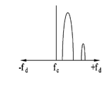
- FIG. 3 is a diagram showing Doppler spectrum when narrow beamforming is performed.
- an antenna array including a plurality of antennas may be installed in a small space with a small antenna. This feature enables pin-point beamforming, pencil beamforming, narrow beamforming, or thin beamforming using tens to hundreds of antennas. This narrow beamforming means that the received signal is received only at a certain angle, not in the same direction.
- FIG. 2A illustrates a case where the Doppler spectrum is U-shaped according to a signal received in an equal direction
- FIG. 2B illustrates a case where narrow beamforming using a plurality of antennas is performed.
- the Doppler spectrum also appears narrower than the U-shape due to the reduced angular spread.
- FIG. 3 it can be seen that Doppler variance appears only in a certain band when the narrow beamforming is performed.
- the center frequency operates in the band of several GHz to several tens of GHz. This characteristic of the center frequency makes the influence of the CFO due to the Doppler effect or the oscillator difference between the transmitter / receiver caused by the movement of the terminal more serious.
- FIG. 4 is a diagram illustrating an example of a synchronization signal service zone of a base station.
- the terminal performs synchronization with the base station by using a downlink (DL) synchronization signal transmitted by the base station.
- DL downlink
- timing and frequency are synchronized between the base station and the terminal.
- the base station transmits the synchronization signal by configuring the beam width as wide as possible so that terminals in a specific cell can receive and use the synchronization signal.
- path loss is greater than that of a low frequency band in synchronizing signal transmission. That is, in the case of a system using a high frequency band, a cell radius that can be supported compared to a conventional cellular system (for example, LTE / LTE-A) using a relatively low frequency band (for example, 6 GHz or less). This is greatly toned.
- a conventional cellular system for example, LTE / LTE-A
- a relatively low frequency band for example, 6 GHz or less
- a synchronization signal transmission method using beamforming may be used.
- the cell radius is increased, but the beam width is reduced. Equation 2 below shows the change in the received signal SINR according to the beam width.
- Equation 2 is the beam width according to the beamforming If received decreases, the received SINR is Fold improvement.
- Another method for solving the reduction of the cell radius may be considered to repeatedly transmit the same sync signal. This method requires additional resource allocation on the time axis, but has the advantage of increasing the cell radius without reducing the beam width.
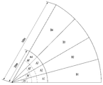
- the base station allocates resources to each terminal by scheduling frequency resources and time resources located in a specific area.
- this specific zone is defined as a sector.
- A1, A2, A3, and A4 represent sectors having a radius of 0 to 200 m and widths of 0 to 15 ', 15 to 30', 30 to 45 ', and 45 to 60', respectively.
- B1, B2, B3, and B4 represent sectors having a radius of 200 to 500 m and widths of 0 to 15 ', 15 to 30', 30 to 45 ', and 45 to 60', respectively.
- sector 1 is defined as ⁇ A1, A2, A3, A4 ⁇
- sector 2 is defined as ⁇ A1, A2, A3, A4, B1, B2, B3, B4 ⁇ .
- the synchronization signal service area of the current base station is sector 1, it is assumed that an additional power of 6 dB or more is required for transmission of the synchronization signal in order for the base station to service the synchronization signal in sector 2.
- the base station can obtain an additional gain of 6 dB using the beamforming technique to serve sector 2.
- the service radius can be increased from A1 to B1.
- A2, A3, and A4 cannot be serviced at the same time. Therefore, when beamforming is performed, a synchronization signal should be separately transmitted to the A2 to B2, A3 to B3, and A4 to B4 sectors. In other words, the base station must transmit a synchronization signal four times beamforming to serve sector 2.
- the base station can transmit the synchronization signal to all sectors 2, but must transmit the synchronization signal four times on the time axis.
- the resources required to service sector 2 are the same for both beamforming and iterative transmission.
- the beam width is narrow, it is difficult for a terminal moving at a high speed or a terminal at the boundary of a sector to stably receive a synchronization signal. Instead, if the ID of the beam in which the terminal is located can be distinguished, there is an advantage that the terminal can determine its own position through a synchronization signal.
- the repetitive transmission scheme since the beam width is wide, it is very unlikely that the terminal misses the synchronization signal. Instead, the terminal cannot determine its location.
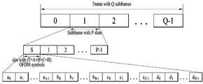
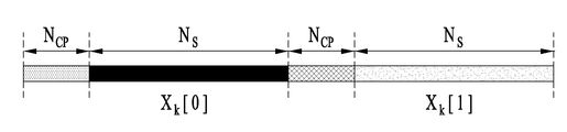
- 5 is an example of a frame structure proposed in a communication environment using mmWave.
- one frame consists of Q subframes and one subframe consists of P slots.
- One slot consists of T OFDM symbols.
- the first subframe in the frame uses the 0 th slot (slot indicated by 'S') for synchronization purposes.
- the 0 th slot is composed of A OFDM symbols for timing and frequency synchronization, B OFDM symbols for beam scanning, and C OFDM symbols for informing the UE of system information. The remaining D OFDM symbols are used for data transmission to each terminal.
- Q, P, T, S, A, B, C, and D may each be arbitrary values and may be values set by a user or automatically set on a system.
- N g , i represent the length of an OFDM symbol, the length of a cyclic prefix (CP), and the index of an OFDM symbol, respectively.
- the algorithm of Equation 3 operates under the condition that two adjacent OFDM received signals in time are the same.
- Such an algorithm can use a sliding window method, which can be implemented with low complexity, and has a strong characteristic of frequency offset.
- Equation 4 represents an algorithm for performing timing synchronization by using a correlation between a received signal and a signal transmitted by a base station.
- Equation 4 denotes a signal transmitted by the base station and is a signal vector previously promised between the terminal and the base station. Equation 4 may produce better performance than Equation 3, but may not be implemented as a sliding window method, and thus requires high complexity. It also has a feature that is vulnerable to frequency offset.
- Beam scanning refers to the operation of the transmitter and / or receiver to find the direction of the beam that maximizes the receiver's received SINR.
- the base station determines the direction of the beam through beam scanning before transmitting data to the terminal.
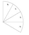
- FIG. 4 illustrates a sector served by one base station divided into eight regions.
- the base station transmits beams in the areas (A1 + B1), (A2 + B2), (A3 + B3), and (A4 + B4), respectively, and the terminal can distinguish beams transmitted by the base station.
- the beam scanning process can be embodied in four processes. First, i) the base station transmits a beam in four areas in sequence. ii) The terminal determines the beam that is determined to be the most suitable among the beams in view of the received SINR. iii) The terminal feeds back information on the selected beam to the base station. iv) The base station transmits data using the beam having the feedback direction. Through the above beam scanning process, the UE can receive downlink data through the beam with optimized reception SINR.
- the Zadoff-Chu sequence is called a chu sequence or ZC sequence and is defined by Equation 5 below.
- N is the length of the sequence
- r is the root value
- a characteristic of the ZC sequence is that all elements have the same size (constant amplitude).
- the DFT results of the ZC sequence also appear the same for all elements.
- Equation (6) the ZC sequence and the cyclic shifted version of the ZC sequence have a correlation as shown in Equation (6).
- the ZC sequence also has a zero auto-correlation property, it is also expressed as having a constant Amplitude Zero Auto Correlation (CAZAC).
- Hadamard matrix is defined as Equation 8 below.
- Equation (8) Denotes the size of the matrix.
- Equation 9 It can be seen from Equation 9 that the columns are orthogonal to each other.
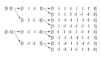
- the OVSF code is generated based on the Hadamard matrix and has a specific rule.
- the first code when branching to the right side of the OVSF code (lower branch), the first code repeats the upper code on the left side twice (mother code), and the second code repeats the high code code once and inverts it once. Is generated. 6 shows a tree structure of the OVSF code.
- All of these OVSF codes are orthogonal except for the relationship between adjacent higher and lower codes on the code tree.
- the code [1 -1 1 -1] is orthogonal to [1 1], [1 1 1 1], and [1 1 -1 -1].
- the OVSF code has the same length as the code length. That is, in FIG. 6, it can be seen that the length of a specific code is equal to the total number of branches to which the corresponding code belongs.
- RACH random access channel
- the base station defines a parameter called 'preambleInitialReceivedTargetPower', and broadcasts the parameter to all terminals in the cell through SIB (System Information Block) 2.
- SIB System Information Block
- the UE calculates a path loss using a reference signal, and determines the transmission power of the RACH signal by using the calculated path loss and the 'preambleInitialReceivedTargetPower' parameter as shown in Equation 10 below.
- P_PRACH_Initial, P_CMAX, and PL represent the transmission power of the RACH signal, the maximum transmission power of the terminal, and the path loss, respectively.
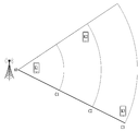
- Equation 10 it is assumed that the maximum transmit power of the terminal is 23 dBm and the RACH reception power of the base station is -104 dBm. In addition, it is assumed that the terminal is arranged as shown in FIG.
- the terminal calculates a path loss using the received synchronization signal and the beam scanning signal, and determines the transmission power based on this.
- Table 3 shows the path loss of the terminal and its transmission power.
- the RACH signal must be transmitted with a very small power (-44 dBm) to match the RACH reception power.
- the path loss is large, but the required transmission power is 6 dBm.
- the base station defines a new precoder consisting of a weighted sum of two or more basic precoders applied to a repeatedly transmitted synchronization signal.
- the base station also defines a plurality of new precoders generated by changing the weighted sum as a codebook.
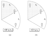
- FIG. 8 a case where the number of repetitive transmissions of the synchronization signal is 2 is illustrated, and a repetitive transmission structure of the synchronization signal for obtaining diversity is illustrated.
- each of the basic precoder We define a new precoder It is defined as In the basic precoder and the new precoder, '0' and '1' represent an order in which a synchronization signal is transmitted, that is, an OFDM symbol.
- the basic precoder and the new precoder are vector matrices, the size of which is equal to the number of antenna ports of the base station. That is, in FIG. And The size of is 4x1 vector.
- the codebook defined by the base station is Expressed as a codebook May be understood as Equation 11 below.
- Precoder in Equation 11 Is the default precoder Precoder Is the default precoder It consists of a difference.
- the precoder corresponding to the upper subsector is ,
- the precoder for the lower subsector Are each defined as At this time, the base station is a new precoder defined by the weighted sum [+1 +1] in the first OFDM symbol
- the new signal is defined as another weighted sum [+1 -1] in the second OFDM symbol. Apply the signal to transmit the synchronization signal. Accordingly, even if the terminal is located at the subsector boundary, it is possible to obtain diversity for the two precoders, thereby accurately distinguishing the synchronization signal.
- the precoder codebook of the synchronization signal is generalized and defined as in Equation 12 below.
- Vector from Equation 12 Denotes a precoder applied to the synchronization signal repeatedly transmitted t-th.
- the sync signal codebook A matrix, defined as, that represents a channel Is the size Is an arbitrary matrix
- the base station selects any one of the codebooks consisting of a weighted sum of basic precoders and a plurality of different new precoders and applies them to the synchronization signal at each repetition. do.
- the number of new precoders included in the codebook may be equal to the number of repetitive transmissions of synchronization signals of the base station.
- the base station in the process of repeatedly transmitting the synchronization signal by the base station, selects a precoder that has not been selected in the codebook and transmits the synchronization signal every repetition. That is, in order to maximize the transmission diversity of the synchronization signal, the base station performs a codebook every repetition of the synchronization signal. Contained in Select a precoder that has not been selected among the two precoders.
- Equation 11 having a repetition number of 2
- the codebook When the base station transmits a synchronization signal in the first OFDM symbol Is selected, and the precoder is used to transmit a synchronization signal in the subsequent second OFDM symbol. Select.
- This process is shown in the structure in which the switch of the RF module is changed on the left side of FIG.
- Sync signals transmitted through the k th antenna among the 4 transmit antennas are the i th sequence And precoder
- Equation 13 is generated as follows.
- Equation (13) Represents an Inverse Discrete Fourier Transform (IDFT) matrix
- Is Represents the k th element of the precoder.
- FIG. 9 illustrates a process in which a synchronization signal in the k-th antenna described in Equation 13 is repeatedly transmitted twice.
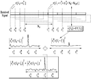
- 10 illustrates a process of estimating sequence and timing by a terminal receiving a synchronization signal. 10 illustrates an operation of a terminal side when a base station repeatedly transmits a synchronization signal according to the embodiment described above.
- Equation 14 an algorithm for synchronizing timing and estimating a sequence from a received synchronization signal may be expressed by Equation 14 below.
- Equation (14) are trial numbers used in estimating timing and sequence, respectively. Denotes a trial number when the value of Equation 14 is maximized, and denotes an index of a timing and a sequence estimated from a synchronization signal received by the terminal.
- Equation 14 may be represented as shown in FIG. Four different timings in Figure 10 Is shown, and the magnitude of the correlation between the received signal and the sequence at each time point is shown. Also, in FIG. 10 Is Represents the received signal vector received at the time point, and the length to be. Is Means the signal after the DFT processing.
- each timing And sequence index Equation 14 is calculated by applying as a trial number.
- the terminal calculates the result of equation (14). Since the correlation value calculated by is the largest, the terminal Is determined as the timing of the synchronization signal, and it is determined that the i th sequence is transmitted.
- Equation 15 the magnitude of the peak value calculated by the UE by Equation 14 is expressed by Equation 15 below.
- Equation (15) Denotes a channel between the transmitter and the receiver.
- the received SNR of the UE from Equation 15 is calculated as in Equation 16 below.
- Equation (16) Denotes a reception SNR when simply transmitting a synchronization signal repeatedly, and SNR proposed represents a reception SNR when the synchronization signal is transmitted by configuring a precoder to obtain diversity according to the proposed embodiment.
- the former doubles the receive power of the sync signal, while the latter receives two channels. And It is expressed as if And If is independent of each other, the diversity gain of the SNR proposed becomes 2.
- Receive power is one channel Since it is expressed only as, the diversity gain is one.
- the synchronization signal since the synchronization signal must be detectable by all terminals in the cell, the most important factor in the synchronization signal is the stability of the communication link. Considering that the higher the diversity gain, the higher the stability of the communication link, the proposed embodiment can obtain an improved effect compared to the conventional synchronization signal transmission method.
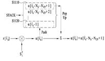
- FIG. 11 illustrates another embodiment of a process in which a terminal synchronizes timing by using a synchronization signal.
- the terminal Obtained in the process of calculating the peak value at the time point Store the values on the stack, The stored value can be used to calculate the peak value at the time point.
- the UE can reduce the computational complexity by avoiding duplicate calculations by utilizing the memory.
- FIG. 11 Is The terminal is currently obtained in the process of calculating the peak value
- a process of storing a value on the stack (S1120) is defined as a 'push' operation, and a process of loading and using a pre-stored value from the stack (S1110) is defined as a 'pop up' operation.
- a process of loading and using a pre-stored value from the stack (S1110) is defined as a 'pop up' operation.
- the total size of the stack is always Is maintained.
- the number of random repetition is defined as in Equation 17 below and the size is Becomes That is, the UE stores the calculated values on the stack for the time interval of the length of the OFDM symbol plus the length of the CP, and recalls the stored values when the time interval corresponding to the length of the OFDM symbol and the length of the CP is over. And new calculations.
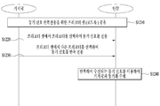
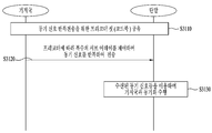
- FIG. 12 is a flowchart illustrating a proposed synchronization signal transmission and reception method.
- the previously proposed and described embodiments are illustrated and described according to a time series flow. Therefore, the above descriptions may be applied to the same or similarly, although not explicitly described in FIG. 12.
- a precoder set (ie, codebook) for repeatedly transmitting a synchronization signal is shared between a base station and a terminal (S1210).
- This codebook consists of a plurality of new precoders composed of weighted sums of basic precoders, and the weighted sum is applied differently to each new precoder. Meanwhile, the codebook may be generated by the base station and transmitted to the terminal, or the terminal may directly generate the codebook.
- the base station selects any one of the precoders constituting the precoder set (codebook) and transmits a synchronization signal (S1220).
- a synchronization signal As the precoder applied to the synchronization signal, any one of the precoders included in the precoder set may be arbitrarily selected.
- the base station selects another precoder from the precoder set (codebook) in the next OFDM symbol and repeatedly transmits a synchronization signal (S1230).
- S1230 any one of the precoders other than the precoder selected in S1220 is selected among the precoder sets. In FIG. 12, it is assumed that the number of repetitive transmissions of the synchronization signal is 2, but when the number of repetitions is higher, the process of S1230 may be repeatedly performed.
- the terminal performs synchronization with the base station by using the synchronization signal repeatedly received (S1240).
- a process may be understood as a process of estimating an optimal value by calculating a correlation between a timing and a sequence of a received synchronization signal, and storing and loading intermediate values on a stack in the process of calculating the correlation. Embodiments may be applied.
- a synchronization signal may be stably transmitted to a terminal.
- Equation 13 illustrates a synchronization signal transmission structure according to FIGS. 8 to 12.
- the reception SNR described in Equation 16 may be expressed as Equation 18 below in consideration of path attenuation.
- the received SNR for the b terminal may be approximated as shown in Equation 19 below.
- Equation 19 means that the diversity gain for the terminal b can be obtained as two.
- Equation 20 means that the diversity gain obtained by terminal a is 1 rather than 2.
- c terminal is reversed Located far from, similar to terminal a, only one diversity gain can be obtained. In other words, according to the embodiments described with reference to FIGS. 8 to 12, sufficient diversity gain can be obtained in the case of terminal b, but not in the case of terminals a and c.
- the terminal must receive the synchronization signal with a certain quality or higher regardless of the position in the cell. Therefore, hereinafter, an embodiment for improving the point that the UEs obtain different diversity gains according to the position in the cell as described above is proposed.
- the 'secondary precoder' is the basic precoder described above. Means.
- the secondary precoder may include two or more 'primary precoders ( Is composed of weighted summation 8 and 12, the plurality of primary precoders ( By the weighted sum of ) Is defined and a new precoder (hereinafter referred to as tertiary precoder) by weighted sum of a plurality of secondary precoders Is defined.
- Equation 21 the relationship between two precoders is expressed according to Equation 21 below.
- Equation 21 Denotes the weights of the primary precoders constituting the i-th secondary precoder as a complex number, that is, how the primary precoders are weighted. Denotes the number of primary precoders constituting the i th secondary precoder, Denotes the index of the secondary precoders constituting the i-th secondary precoder.
- Equation 22 shows an example in which the secondary precoders are composed of a weighted sum of two primary precoders.
- the secondary precoder may be implemented in a form in which a specific primary precoder is multiplied by a j or -j value that changes a phase.
- the primary precoders may be designed to equally divide the area where the synchronization signal is transmitted.
- the primary precoders are designed such that each beam is formed by 30 'to equally divide 120' which is a synchronization signal transmission region.
- the primary precoders may be designed such that a minimum chordal distance between each other is maximized.
- the minimum codal distance means the spacing between beams by the precoder
- the maximum codal distance means the maximum spacing between the beams formed by the precoders, that is, the correlation between the beams is minimized.
- the primary precoder may be designed to maximize the minimum codal distance using the DFT codebook.
- 15 to 17 are diagrams illustrating a synchronization signal transmission structure according to another embodiment.
- embodiments of designing a second precoder using a first precoder in addition to the above descriptions will be described.
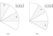
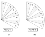
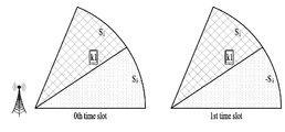
- the secondary precoder is composed of a weighted sum of the primary precoders and may be designed in a comb structure.
- the comb structure means that the regions in the subsectors of the primary precoders constituting the secondary precoder are not neighboring as shown in FIG. 14, and the minimum distances of the regions in the subsectors of the primary precoders are the same.
- the secondary precoder in Fig. 15 (a) Primary precoder to construct Wow The regions of do not neighbor each other, and the secondary precoder in FIG. Primary precoder to construct Wow The areas of do not neighbor each other. Furthermore, the second precoder Primary Precoders Composing Wow The minimum distance of the region in the subsector of 30 'is the second precoder Primary Precoders Composing Wow The minimum distance of the region in the subsector of is also equal to 30 '. 2nd precoder Beam area of the secondary precoder It may be understood that the beam area of P is shifted by 30 '.
- Equation 23 when the secondary precoder is configured using the primary precoder according to the above-described embodiment, the third precoders of Equation 11 may be expressed as Equation 23 below.
- Equation (23) Looking at the sign of, it can be seen that the phase of the synchronization signal is inverted with respect to some region in the subsector in the second time interval.
- FIG. 16 illustrates a case where a secondary precoder is designed according to an exemplary embodiment.
- the phase of is reversed.
- the phase change of the beam for each time interval is described for each of the regions 1610, 1620, and 1630 shown, the phase of the beam is changed over the first time interval and the second time interval for the region 1610.
- the beam phase is changed over a total of two time intervals For the area 1630 To change.
- the terminal a of the embodiment of FIG. 16 is adjacent to the beam over two time intervals. Undergoes a phase change. Accordingly, the terminal a may obtain a diversity gain of 2 for the synchronization signal. Similarly, terminal b is a beam Undergoes a phase shift of By undergoing a phase change of, all terminals in the subsector can obtain the same diversity gain.
- FIG. 17 illustrates an embodiment of narrower design of an area within a subsector corresponding to primary precoders.
- four primary precoders are assumed, while in FIG. 17, a secondary precoder is designed through eight primary precoders.
- the terminal receiving the synchronization signal may obtain a more uniform diversity gain than in the embodiment of FIGS. 14 to 16.
- FIG. 18 is a flowchart illustrating a synchronization signal transmission and reception method according to another embodiment.
- FIG. 18 the previously proposed and described embodiments are illustrated and described according to a time series flow. Therefore, the above descriptions may be applied to the same or similarly, although not explicitly described in FIG. 18.
- a precoder set (ie, a codebook) for repeatedly transmitting a synchronization signal is shared between a base station and a terminal (S1810).
- a codebook may consist of tertiary precoders composed of weighted sums of secondary precoders, and the weighted sum is applied differently to each secondary precoder.
- the secondary precoders are composed of weighted sums of other primary precoders, and the secondary precoders do not have neighboring regions in the subsectors of the primary precoders constituting each secondary precoder, and the primary The minimum distances of the regions in the subsectors of the precoders may be designed in the same comb structure.
- the codebook may be generated by the base station and transmitted to the terminal, and the terminal may directly generate the codebook as described above with reference to FIG. 12.
- the base station selects any one of the third precoders constituting the precoder set (codebook) and transmits a synchronization signal (S1820).
- the third precoder applied to the synchronization signal any one of the third precoders included in the precoder set may be arbitrarily selected.
- the base station selects another third-order precoder of the precoder set (codebook) in the next OFDM symbol and repeatedly transmits a synchronization signal (S1830).
- S1830 any one of the precoder sets, except for the precoder selected in S1820, is selected. In FIG. 18, it is assumed that the number of repetitive transmissions of the synchronization signal is 2, but when the number of repetitions is higher, the process of S1830 may be repeatedly performed.
- the terminal performs synchronization with the base station using the repeatedly received synchronization signal (S1840).
- This process may be understood as a process of estimating an optimal value by calculating a correlation between the timing and the sequence of the received synchronization signal.
- an embodiment in which the terminal stores and retrieves intermediate values in a stack may be applied in the process of calculating correlation.
- the stability of the communication link is secured.
- the synchronization signal may be transmitted to the terminals in the cell with a constant diversity gain without additional signaling overhead.
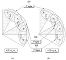
- 19 and 20 illustrate a structure of transmitting a synchronization signal and a beam scanning signal for explaining another proposed embodiment. 19 and 20 will be described a synchronization process and a beam scanning process according to the above-described synchronization signal transmission and reception method.
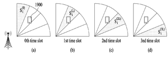
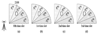
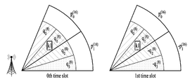
- FIG. 19 illustrates a process of a base station switching four beams during four time slots and transmitting a synchronization signal.
- the terminal performs a synchronization process using the received synchronization signals, and simultaneously performs a beam scanning process.
- the terminal 1900 performs synchronization through the second beam (FIG. 19 (b)) in which the reception power is sensed the largest, and the base station can determine that the beam selected by the terminal can be distinguished from other beams. Map beams in different sequences.
- the terminal 1900 has a sequence of beams selected by itself. It can be seen that the beam scanning process is performed by feeding back the selected beam to the base station.
- the signal transmitted by the base station is designed based on the Zadoff-Chu (ZC) sequence.
- the cell ID of the base station may be used as a root value of the ZC sequence, and the beam ID may be used as a cyclic shift value of the ZC sequence.
- a sequence The root value in And the cyclic shift value is Defined as
- Is a system parameter value and is generally set to be greater than the channel's delay spread maximum. Terminal sequence Using three cells and four beams of each cell can be distinguished, and this process is expressed by Equation 24 below.
- the terminal simultaneously performs timing synchronization, cell ID estimation, and beam ID estimation through Equation 24, and this process is represented in FIG.
- the terminal is configured to include a total of 12 correlators in order to simultaneously distinguish three cells and four beams, and 12 correlators operate together in every time slot.
- the terminal since only the cell needs to be distinguished, the terminal is configured to include a total of three correlators.
- the mmWave communication system includes a beam scanning process, requiring four times the processing power of LTE. As a result, according to the scheme proposed above, the computational complexity required for the synchronization process of the terminal is increased four times.
- 21 to 23 illustrate a structure of transmitting a synchronization signal and a beam scanning signal according to a proposed embodiment.
- the beam ID is defined as weights applied to the weighted sum of the aforementioned basic precoder (or the secondary precoder).
- Equation 25 shows a synchronization signal codebook when the number of repetitions is two.
- Equation 25 uses the codebook described in Equation 11 as a weighting matrix ( ).
- First column in equation (25) Each element of Is the primary precoder (secondary precoder) Represents the weight over time. Similarly, the second column Each element of the second precoder Represents the weight over time.
- the base station and the terminal Each Beam ID and Is determined by the beam ID.
- each column constituting a codebook (that is, a weight matrix) applied to the transmission of the synchronization signal is used as a beam ID for distinguishing each beam in the beam scanning process. That is, since the base station can transmit the beam ID to the terminal through the weight matrix, the base station can deliver the beam ID for the beam scanning process to the terminal even without additional signaling.
- Equation 26 the case where the number of repetition of the synchronization signal is 4 will be described using Equation 26 as an example.
- Equation (26) is a representation of the codebook when the number of repetitions of the synchronization signal is 4 by a weight matrix. Similar to the equation (25), the first, second, third and fourth columns of the weight matrix Are defined as beam IDs.
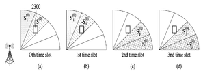
- each beam is transmitted as shown in FIG. 21 during four timeslots.
- FIG. 21 unlike FIG. 19, four beams are simultaneously transmitted in each timeslot, and the sign of the transmitted sequence varies according to the timeslot.
- beams transmitted to respective regions within a sector are directed from the top to the bottom. Corresponds to each. That is, the beam transmitted to the uppermost region And the beam transmitted in the lowest region Corresponds to.
- the terminal when the synchronization signal is transmitted, the terminal performs synchronization according to Equation 27 below to estimate timing synchronization and a sequence (cell ID) of the synchronization signal.
- Equation 27 the beam scanning process for estimating the beam ID is not performed simultaneously with the synchronization process.
- the number of correlators of the terminal is reduced to 4 as compared to 12 of FIG. 20 as shown in FIG.
- the computational complexity of the terminal is greatly reduced, which may solve the above-described problem.
- the following describes a process of performing beam scanning after the terminal performs synchronization to estimate timing synchronization and sequence.
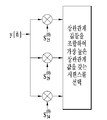
- Equation 29 The terminal performs a beam scanning process based on Equation 28. First, by multiplying both sides of Equation 28 by the inverse of the weight matrix, Equation 29 may be obtained.
- Equation 29 the result calculated through the matrix operation is represented by Equation 30 below.
- the terminal compares four power values obtained according to Equation 30, and selects the largest value. For example, the element of the first row If the value appears to be the largest, the terminal end It can be understood as larger. That is, the terminal in FIG. It can be seen that the beam of the first region generated by is received more strongly than the beams of the other regions. In other words, the terminal may know that it is located in the first area within the sector. That is, the terminal Value is the first column of the weight matrix This is because it knows that the value is calculated using, and as the codebook is shared between the base station and the terminal end This is because the UE knows in advance that it is mapped to. That is, since the UE knows in advance the beam ID mapped to the column selected from the weight matrix, the beam matrix may be performed even if the beam ID is not separately received by calculating the weight matrix.
- an element in Equation 30 If the value of appears to be the largest, the terminal You can see that the value is the largest. That is, the terminal in FIG. It can be seen that the beam of the last region generated by is received more strongly than the beam of the other region. Accordingly, the terminal has a position in its sector It can be seen that the last region corresponding to.
- the terminal may distinguish the beams by using the weight matrix of the synchronization signal repeatedly received (that is, the beam scanning process may be May be performed).
- the terminal may distinguish the beams. Accordingly, the number of sequences to be found by the terminal in timing estimation is reduced by the number of cell IDs, and the synchronization complexity of the terminal is greatly reduced.
- the columns of the weight matrix may be configured to be orthogonal to each other.
- Equations 25 and 26 represent weight matrices when the number of repetitions is 2 or 4, respectively.
- a process of applying an inverse of the weight matrix in Equation 28 may be simplified.
- the columns of the weighting matrix are configured to be orthogonal to each other, meaning that the vector representing the weighted sum applied to the primary (secondary) precoder in one time slot is orthogonal to the vector representing the weighted sum applied to another time slot. it means.
- This means that the sync signal codebook Each vector constituting It may be understood that codebooks are designed to allow each other to work together. Such a vector may be understood as an orthogonal cover code (OCC) in that codes are orthogonal to each other.
- OCC orthogonal cover code
- the codebook may be designed using a Hadamard matrix described in Equation 8, or may be designed using a DFT matrix.
- the Hadamard matrix can be simply generated for any number of iterations, and the implementation complexity is very low because the values of each element are defined by addition and subtraction only.
- the DFT matrix can also be simply generated for any number of iterations, where the values of each element (N is the number of repetitions). For example, the DFT matrix when the number of repetitions is 4 may be generated as in Equation 31 below.
- the DFT matrix In the case of the DFT matrix, if the number of repetitions is 2, the complexity is the same as that of the Hadamard matrix. If the number of repetitions is 4 or less, the DFT matrix can be generated simply by changing the phase. The rise can be minimized.
- the beam ID may be defined by both a weight and a sequence applied to the basic precoder.
- the embodiments described with reference to FIGS. 21 and 22 when the channel changes rapidly while the synchronization signal is repeatedly transmitted, the performance of beam scanning may be degraded.
- the embodiment illustrated in FIG. 23 proposes a method of generating a beam ID by considering not only a weight matrix but also a sequence.
- the base station performs two consecutive timeslots. Are transmitted simultaneously, and in FIG. 23 (c) and FIG. 23 (d), the base station Send simultaneously.
- the base station is transmitted in the first two timeslots Transmitted in the two timeslots
- the first two timeslots contain a sequence ((A) and (b)), and in the following two timeslots, the sequence Are allocated (Figs. 23 (c) and 23 (d)).
- the number of correlators of the terminal increases by that amount.
- the section in which the channel should not be changed is reduced to two timeslots, thereby making it more robust to sudden changes in the channel.
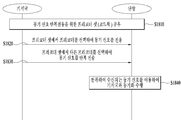
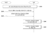
- FIG. 24 is a flowchart illustrating a synchronization process and a beam scanning process according to another embodiment of the present disclosure.
- FIG. 24 the previously proposed and described embodiments are illustrated and described according to a time series flow. Therefore, although not explicitly described with reference to FIG. 24, the contents described above with reference to FIGS. 19 to 23 may be identically or similarly applied.
- a precoder set (ie, a codebook) for repeatedly transmitting a synchronization signal is shared between a base station and a terminal (S2410).
- a codebook may consist of tertiary precoders composed of weighted sums of secondary precoders, and the weighted sum is applied differently to each secondary precoder.
- each of the weighting vectors (ie, OCCs) used for generation of the third order precoders constituting the precoder set may be configured to be orthogonal to each other.
- the codebook may be generated by the base station and transmitted to the terminal, and the terminal may directly generate the codebook as described above with reference to FIG. 12. In this process, the weighted sum applied to each tertiary precoder indicates the beam ID of the base station.
- the base station selects any one of the third precoders constituting the precoder set (codebook) and transmits a synchronization signal (S2420).
- the third precoder applied to the synchronization signal any one of the third precoders included in the precoder set may be arbitrarily selected.
- the base station selects another third-order precoder of the precoder set (codebook) in the next OFDM symbol and repeatedly transmits a synchronization signal (S2430).
- S2430 any one of the precoder sets, except for the precoder selected in S2420, is selected. In FIG. 24, it is assumed that the number of repetitive transmissions of the synchronization signal is 2, but if the number of repetitions is higher, the process of S2430 may be repeatedly performed.
- the terminal performs synchronization with the base station by using the synchronization signal repeatedly received (S2440).
- This process may be understood as a process of estimating an optimal value by calculating a correlation between the timing and the sequence of the received synchronization signal.
- an embodiment in which the terminal stores and retrieves intermediate values in a stack may be applied in the process of calculating correlation.
- the terminal When the synchronization is completed by estimating the timing and the sequence for each timeslot in S2440, the terminal performs the beam scanning process using the synchronization signals received in S2420 and S2430 (S2450). That is, the terminal performs the process described in Equation 28 to Equation 30 with respect to the correlation values obtained while performing synchronization for each time slot, and accordingly, the UE can distinguish the most strongly received beam from among the plurality of beams. have. Through this beam scanning process, the terminal can distinguish its own position (ie, subsector) in the sector.
- the base station introduces OCC into the codebook, thereby allowing the terminal to perform beam scanning without allocating an additional sequence for beam scanning. Accordingly, the terminal can minimize the increase in complexity for implementing the beam scanning process.
- the beam broadening technique will be described before explaining the proposed embodiment.
- the size of a linear antenna array If, the beamforming gain is Although proportional to, the beam width or half power beam width (HPBW) Inversely proportional to Therefore, the larger the size of the linear antenna array, the better beamforming gain can be obtained, while the beam width becomes narrower.
- a broadcast channel or a control channel requires a wide beam width while requiring a low SNR, a relatively high beamforming gain is not required.
- a large antenna arrangement requires a new beamforming design to satisfy the above-described characteristics.
- the beamforming design described below is called a beam extension technique.
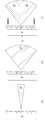
- FIG. 25A beamwidths of eight antenna arrays are shown.
- the width of the beam generated by the antenna array including eight antennas is 15 ', Is a vector representing the coefficients of the linear antenna array.
- FIG. 25 (b) shows the result of applying the beam extension technique to the antenna arrangement of FIG. 25 (a).
- FIG. 25 (b) shows the beamwidth when only two of the eight antennas are on (on) and the remaining antennas are off (off).
- Figure 25 (b) Represents the first column of the DFT matrix of size 2, Is in a relationship.
- the number of antennas involved in beamforming is reduced to one quarter, while the beam width is expanded four times from 15 'to 60' and the beamforming gain is reduced by 6.6227 dB.
- This method not only has a beamforming loss but also has a low efficiency due to power loss when assuming an active antenna system (AAS) to be described later.
- AAS active antenna system
- FIG. 25 (c) shows the result of applying another beam extension technique.
- eight antennas are divided into two subarrays (or subarrays), and each subarray is defined as four consecutive antennas.
- the first subarray and the second subarray are coefficients of the second and fourth columns of the DFT matrix of size 4, respectively. Has, Satisfies the relationship.
- each sub-array is composed of four antennas and has a beam width of 30 ', and the beamforming gain is reduced by 4.8165 dB.
- the total beam width satisfies 60 '.
- the beam extension technique of FIG. 25 (c) does not cause power loss since all antennas are operating.
- the size of all antenna coefficients is equal to 1 while two multiple beams are transmitted.
- the size of a linear antenna array ego
- the ratio of the expanded beamwidth Becomes
- the beam extension technique incorporating the sub-array concept of FIG. 25 (c) is a method that can extend the beam width while using all antennas.
- the precoder applied to the synchronization signal is a weighted sum of basic precoders (or secondary precoders) as described in Equation 12.
- the size of each element of the sync signal precoder is different.
- the default precoder Are different columns of a DFT matrix having a size of 4, and consider a case defined as Eq.
- Equation 33 the synchronization signal codebook described with reference to FIG. 21 is defined as in Equation 33.
- each element has a different size from the basic precoder.
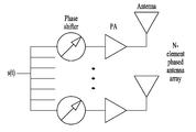
- an AAS having a phase shifter and a power amplifier for each antenna is considered.
- the phase and magnitude of each element of the sync signal precoder are implemented by a phase shifter and a power amplifier of an individual antenna corresponding to the element.
- a signal In order to minimize power loss under such an AAS antenna structure, a signal must be transmitted by changing a phase for each antenna while the outputs of all power amplifiers are the same. This process assumes that the coefficients of the precoder are the same. However, as described above, the precoder coefficient of the synchronization signal may vary depending on the configuration of the antenna, and thus may not satisfy this condition, resulting in power loss.
- the beam extension technique is a technique for transmitting a beam by controlling all subarrays independently by grouping all antennas. In this case, it is possible to control the beam direction by adjusting only the phase in a state where the power amplifier outputs of all the antennas are fixed in the same manner.
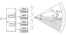
- FIG. 27 shows an example of an antenna arrangement with 32 antennas and four subarrays. In this case, each sub-array is configured to include eight antennas and generates a beam having a width of 15 '. Each sub-array may individually control the direction of the generated beam, so that the beam structure of FIG. 27 may be comprehensively implemented.
- FIG. 27 a precoder corresponding to each subarray is shown.
- the coefficient size of each precoder is the same and only the phase is different.
- the synchronization signal precoder used in the synchronization process is defined as a stack of two or more basic precoders (or the above-described secondary precoders).
- the respective sync signal precoders are defined by different weights of the respective basic precoders. Equation 34 further illustrates the concept that the synchronization signal precoder is defined as a stack of basic precoders.
- each precoder included in the sync signal codebook includes four basic precoders ( ) Is designed to be concatenated in the column direction. In this case, the weights of the respective basic precoders to be concatenated are defined differently for each tertiary precoder.
- Equation (35) Is the size Phosphorus vector Is a diagonal matrix with diagonal components.
- vector May be defined as a matrix as in Equation 36 below, and the matrix of Equation 36 is the weight matrix described above. The size of the weight matrix is to be.
- the third order precoders defined by Equations 34 to 36 are composed of a plurality of concatenated basic precoders, and each basic precoder performs beamforming by independently controlling antenna subarrays.
- Equation 37 the received signal of the terminal may be expressed as Equation 37 below.
- Equation 38 Received signal in equation 37 And sequence Correlation values between Equation 37 is expressed as Equation 38.
- Equation 38 is the same as Equation 28.
- the beam scanning process to which the sub-array concept and the beam extension technique are applied can be performed in the same manner as the above-described embodiment. That is, although the base station does not separately generate or allocate a beam ID for the beam scanning process, the terminal distinguishes beams by using a weight matrix of synchronization signals repeatedly received according to the embodiments described in Equations 28 to 30. (I.e., the beam scanning process is performed). In the beam scanning process, the UE may estimate the reception power of each of the beams, and select the beam having the best reception power based on this.
- the synchronization signal codebook is defined as third-order precoders generated by concatenating basic precoders by utilizing the fact that the coefficient sizes of the synchronization signal codebooks are the same. Accordingly, the beam scanning process can be designed in the same manner as previously proposed while minimizing the power loss during the synchronization process.
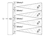
- FIG. 28 shows another embodiment of the proposed method.
- a sequence input to each radio frequency chain is changed every time slot.
- the third precoder is designed differently for each time slot while inputting the same sync sequence in all time slots, in FIG. 28, the sync sequence is input differently for each time slot with the third precoder kept the same. That's the way.
- the RF chains are connected one by one.
- Sync sequence through each RF chain Is input, and different synchronization sequences may be transmitted and input for each RF chain.
- all time slots Send it.
- sequences are generated during four time slots (TS). Are entered in order.
- the sync signal precoder (third precoder) Is defined as in Equation 39, and has the same value for four time slots.
- the rightmost side of (40) is the same as the rightmost side of (37).
- the same result can be obtained by changing the input synchronization sequence in accordance with the time slot, instead of the scheme of FIG. 27 in which the synchronization signal precoder is changed in accordance with the time slot.
- the terminal may perform the same synchronization process and beam scanning process described above with reference to FIG. 28.
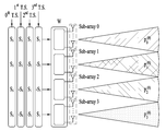
- the third precoders constituting the codebook are defined as a plurality of concatenated basic precoders (secondary precoders).
- the basic precoders may be defined by concatenating two or more primary precoders.
- the beam of the secondary precoder will comprise beams of contiguous primary precoders.
- Secondary precoder in FIG. 29 Is the first precoder as Are defined by concatenating them.
- the superscript of each precoder indicates the size of the corresponding precoder, and the subscript indicates the precoder index.
- Beam in Figure 29 Silver two beams It is designed to include. That is, according to the embodiment of FIG. 29, the primary (secondary) precoder having the wide beam 30 ′ is defined by concatenating the primary precoders having the narrow beam 15 ′. Furthermore, the sync signal codebook defined by concatenating the basic precoder may be expressed as in Equation 42.
- the terminal has a wide beam. Can be distinguished, while having a narrow beam Cannot be distinguished. That is, according to the embodiment of FIG. 30, the time slot required for sequence transmission is reduced by half compared to FIG. 21, but the beam resolution is also reduced by half.
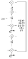
- FIG. 31 is a flowchart illustrating a synchronization method according to a proposed embodiment.
- the embodiments proposed and described with reference to FIGS. 25 to 30 are illustrated and described according to a time series flow, and the above descriptions may be identically or similarly applied, even if not explicitly described with reference to FIG. 31.
- a precoder set for repeatedly transmitting a synchronization signal is shared between a base station and a terminal (S3110).
- a codebook may consist of tertiary precoders generated by concatenating secondary precoders.
- the weights applied to the respective secondary precoders to configure the tertiary precoder may be defined differently for each of the plurality of tertiary precoders constituting the precoder set.
- the weights applied to the secondary precoders are the same in magnitude and differ only in phase.
- each of the secondary precoders corresponds to an antenna sub-array of some antennas constituting the antenna array of the base station.
- the codebook may be generated by the base station and transmitted to the terminal, or the terminal may directly generate the codebook.
- the base station selects any one of the third precoders constituting the precoder set (codebook) and transmits a synchronization signal (S3120).
- the third precoder applied to the synchronization signal any one of the third precoders included in the precoder set may be arbitrarily selected.
- the base station selects another third-order precoder of the precoder set (codebook) in the next OFDM symbol and repeatedly transmits a synchronization signal. In each iteration, the base station selects one of the third precoders except for the precoder which is already selected, and transmits a synchronization signal.
- the base station controls the antenna sub-arrays through each of the plurality of concatenated secondary precoders constituting the tertiary precoder. Since each of the secondary precoders corresponds to an antenna subarray, the base station can achieve the beam extension technique by controlling the plurality of antenna subarrays through the tertiary precoder applied in one time slot.
- the terminal performs synchronization with the base station by using the synchronization signal repeatedly received (S3130).
- This process may be understood as a process of estimating an optimal value by calculating a correlation between the timing and the sequence of the received synchronization signal.
- an embodiment of storing and recalling intermediate values on a stack may be applied in the process of calculating correlation.
- the terminal may repeatedly perform a beam scanning process using the received synchronization signals. That is, the terminal performs the process described in Equation 28 to Equation 30 with respect to the correlation values obtained while performing synchronization for each time slot, and accordingly, the UE can distinguish the most strongly received beam from among the plurality of beams. have. Through this beam scanning process, the UE can distinguish its own position (ie, subsector) in the sector, and the beam scanning process may be similarly applied to the process described with reference to FIG. 24.
- each of the secondary precoders constituting the tertiary precoder may be defined by concatenating a plurality of primary precoders.
- hybrid beamforming the analog beamforming is fixed while the digital beamforming process is reduced to reduce the feedback burden of the terminal.
- the analog beamforming is defined differently for each antenna sub-array so that the beam extension technique is applied.
- Hybrid beamforming is not suitable for synchronous signal transmission because the envelope of the beamforming is fixed.
- the beamforming is widely extended and thus the synchronous signal transmission is more efficient.
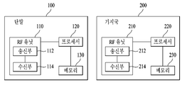
- FIG. 32 is a diagram illustrating a configuration of a terminal and a base station according to an embodiment of the present invention.
- the terminal 100 and the base station 200 may include radio frequency (RF) units 110 and 210, processors 120 and 220, and memories 130 and 230, respectively.
- FIG. 32 illustrates only a 1: 1 communication environment between the terminal 100 and the base station 200, a communication environment may also be established between a plurality of terminals and a plurality of base stations.
- the base station 200 illustrated in FIG. 32 may be applied to both the macro cell base station and the small cell base station.
- Each RF unit 110, 210 may include a transmitter 112, 212 and a receiver 114, 214, respectively.
- the transmitting unit 112 and the receiving unit 114 of the terminal 100 are configured to transmit and receive signals with the base station 200 and other terminals, and the processor 120 is functionally connected with the transmitting unit 112 and the receiving unit 114.
- the transmitter 112 and the receiver 114 may be configured to control a process of transmitting and receiving signals with other devices.
- the processor 120 performs various processes on the signal to be transmitted and transmits the signal to the transmitter 112, and performs the process on the signal received by the receiver 114.
- the processor 120 may store information included in the exchanged message in the memory 130.
- the terminal 100 can perform the method of various embodiments of the present invention described above.
- the transmitter 212 and the receiver 214 of the base station 200 are configured to transmit and receive signals with other base stations and terminals, and the processor 220 is functionally connected to the transmitter 212 and the receiver 214 to transmit the signal. 212 and the receiver 214 may be configured to control the process of transmitting and receiving signals with other devices.
- the processor 220 may perform various processing on the signal to be transmitted, transmit the signal to the transmitter 212, and may perform processing on the signal received by the receiver 214. If necessary, the processor 220 may store information included in the exchanged message in the memory 230. With such a structure, the base station 200 may perform the method of the various embodiments described above.
- Processors 120 and 220 of the terminal 100 and the base station 200 respectively instruct (eg, control, coordinate, manage, etc.) the operation in the terminal 100 and the base station 200.
- Respective processors 120 and 220 may be connected to memories 130 and 230 that store program codes and data.
- the memories 130 and 230 are coupled to the processors 120 and 220 to store operating systems, applications, and general files.
- the processor 120 or 220 of the present invention may also be referred to as a controller, a microcontroller, a microprocessor, a microcomputer, or the like.
- the processors 120 and 220 may be implemented by hardware or firmware, software, or a combination thereof.
- ASICs application specific integrated circuits
- DSPs digital signal processors
- DSPDs digital signal processing devices
- PLDs programmable logic devices
- FPGAs Field programmable gate arrays
- the above-described method may be written as a program executable on a computer, and may be implemented in a general-purpose digital computer which operates the program using a computer readable medium.
- the structure of the data used in the above-described method can be recorded on the computer-readable medium through various means.
- Program storage devices that may be used to describe storage devices that include executable computer code for performing the various methods of the present invention should not be understood to include transient objects, such as carrier waves or signals. do.
- the computer readable medium includes a storage medium such as a magnetic storage medium (eg, a ROM, a floppy disk, a hard disk, etc.), an optical reading medium (eg, a CD-ROM, a DVD, etc.).
- the method of performing synchronization as described above may be applied to various wireless communication systems including not only 3GPP LTE and LTE-A systems, but also IEEE 802.16x and 802.11x systems. Furthermore, the proposed method can be applied to mmWave communication system using ultra high frequency band.
Abstract
Disclosed are a synchronization signal transmission method and a base station, in which beamforming of synchronization signals is performed in the following manner: a codebook is configured by defining a plurality of third precoders by connecting basic precoders which respectively correspond to a plurality of antenna subarrays, the synchronization signals are repeatedly transmitted to a terminal by applying the third precoders selected from the codebook to a synchronization sequence across a plurality of time intervals, and the plurality of antenna subarrays are independently controlled by first precoders respectively corresponding thereto.
Description
이하의 설명은 무선 통신 시스템에 대한 것으로, 보다 구체적으로는 무선랜 시스템에서 동기 신호용 코드북을 이용한 동기 신호 전송 방법 및 그 장치에 대한 것이다.The following description relates to a wireless communication system, and more particularly, to a synchronization signal transmission method and apparatus using a synchronization signal codebook in a WLAN system.
밀리미터 웨이브(mmWave)를 이용한 초고주파 무선 통신 시스템은 중심 주파수가 수 GHz 내지 수십 GHz에서 동작하도록 구성된다. 이러한 중심 주파수의 특성으로 인하여 mmWave 통신 시스템에서는 음영 지역에서 경로 감쇄(path loss)가 두드러지게 나타날 수 있다. 동기 신호는 기지국의 커버리지 내에 위치하는 모든 단말에 안정적으로 전송되어야 한다는 점을 고려할 때, mmWave 통신 시스템에서는 상술한 초고주파 대역의 특성상 발생할 수 있는 잠재적인 deep-null 현상을 고려하여 동기 신호를 설계 및 송신해야 한다.Ultra-high frequency wireless communication systems using millimeter wave (mmWave) are configured such that the center frequency operates at a few GHz to several tens of GHz. Due to the characteristics of the center frequency, path loss may be prominent in the shadow area in the mmWave communication system. Considering that the synchronization signal should be stably transmitted to all terminals located within the coverage of the base station, the mmWave communication system designs and transmits the synchronization signal in consideration of the potential deep-null phenomenon that may occur due to the characteristics of the ultra-high frequency band described above. Should be.
본 발명은 상기한 바와 같은 문제점을 해결하기 위하여 안출된 것으로서, 본 발명의 목적은 무선 통신 시스템에서 기지국과 단말 간의 동기화 과정을 개선하여 동기화 과정의 효율을 개선하는 것이다.The present invention has been made to solve the above problems, an object of the present invention to improve the synchronization process between the base station and the terminal in the wireless communication system to improve the efficiency of the synchronization process.
본 발명의 또 다른 목적은, 동기 신호 전송을 위한 코드북을 제안함으로써 동기 시퀀스에 적용되는 프리코더 성능을 개선하는 것이다. Another object of the present invention is to improve the precoder performance applied to a synchronization sequence by proposing a codebook for the transmission of the synchronization signal.
본 발명의 또 다른 목적은, 동기 신호 전송 과정의 성능을 유지하면서도 전력 손실을 최소화하는 것이다.Another object of the present invention is to minimize power loss while maintaining the performance of the synchronization signal transmission process.
본 발명에서 이루고자 하는 기술적 목적들은 이상에서 언급한 사항들로 제한되지 않으며, 언급하지 않은 또 다른 기술적 과제들은 이하 설명할 본 발명의 실시 예들로부터 본 발명이 속하는 기술분야에서 통상의 지식을 가진 자에 의해 고려될 수 있다.Technical objects to be achieved in the present invention are not limited to the above-mentioned matters, and other technical problems not mentioned above are provided to those skilled in the art from the embodiments of the present invention to be described below. May be considered.
상기 기술적 과제를 해결하기 위한 동기 신호 전송 방법은, 복수의 안테나 부배열(antenna subarray)들 각각에 대응하는 복수의 제1 프리코더들의 연접(concatenation)으로 정의되는 제2 프리코더들로 구성되는 코드북을 획득하는 단계, 및 복수의 시간 구간에 걸쳐서 코드북에서 선택된 서로 다른 제2 프리코더들을 동기 시퀀스에 적용함으로써, 단말에 동기 신호를 반복하여 전송하는 단계를 포함하고, 복수의 안테나 부배열들은 각각에 대응되는 제1 프리코더에 의해 서로 독립적으로 제어되어 동기 신호의 빔포밍을 수행한다.According to another aspect of the present invention, there is provided a synchronization signal transmission method including a codebook including second precoders defined as concatenation of a plurality of first precoders corresponding to each of a plurality of antenna subarrays. Acquiring a signal, and repeatedly transmitting a synchronization signal to the terminal by applying different second precoders selected from the codebook over a plurality of time intervals to the synchronization sequence, wherein the plurality of antenna subarrays are assigned to each terminal. Independently controlled by the corresponding first precoder to perform beamforming of the synchronization signal.
하나의 제2 프리코더는 가중치가 적용된 복수의 제1 프리코더들의 연접으로 정의되며, 가중치는 코드북을 구성하는 복수의 제2 프리코더 별로 서로 다를 수 있다.One second precoder is defined as a concatenation of a plurality of weighted first precoders, and the weights may be different for each of the plurality of second precoders constituting the codebook.
복수의 제1 프리코더들에 적용되는 가중치는 크기는 모두 같고 위상이 서로 다를 수 있다.The weights applied to the plurality of first precoders may have the same magnitude and different phases.
복수의 제1 프리코더들 각각은 제1 프리코더보다 더 좁은 빔을 구성하는 제3 프리코더들의 연접으로 정의될 수 있다.Each of the plurality of first precoders may be defined as a concatenation of third precoders constituting a narrower beam than the first precoder.
동기 시퀀스는 복수의 시간 구간에 걸쳐서 동일하게 유지될 수 있다.The synchronization sequence may remain the same over a plurality of time intervals.
복수의 안테나 부배열 각각은 기지국의 RF 체인(Radio Frequency chain)에 대응할 수 있다.Each of the plurality of antenna subarrays may correspond to an RF chain of a base station.
상기 기술적 과제를 해결하기 위한 기지국은, 송신부, 수신부, 및 송신부 및 수신부와 연결되어 동작하는 프로세서를 포함하되, 프로세서는, 복수의 안테나 부배열(antenna subarray)들 각각에 대응하는 복수의 제1 프리코더들의 연접(concatenation)으로 정의되는 제2 프리코더들로 구성되는 코드북을 획득하고, 복수의 시간 구간에 걸쳐서 코드북에서 선택된 서로 다른 제2 프리코더들을 동기 시퀀스에 적용함으로써, 단말에 동기 신호를 반복하여 전송하되, 복수의 안테나 부배열들은 각각에 대응되는 제1 프리코더에 의해 서로 독립적으로 제어되어, 동기 신호의 빔포밍을 수행한다.The base station for solving the technical problem includes a transmitter, a receiver, and a processor operating in connection with the transmitter and the receiver, the processor, a plurality of first free corresponding to each of the plurality of antenna subarrays (antenna subarray) Acquiring a codebook consisting of second precoders defined by concatenation of coders, and applying different second precoders selected from the codebook to the synchronization sequence over a plurality of time intervals, thereby repeating the synchronization signal to the terminal. The plurality of antenna sub-arrays are controlled independently by each other by a first precoder corresponding to each other to perform beamforming of a synchronization signal.
상기 기술적 과제를 해결하기 위한 또 다른 동기 신호 전송 방법은, 복수의 안테나 부배열(antenna subarray)들 각각에 대응하는 복수의 제1 프리코더들의 연접(concatenation)으로 정의되는 제2 프리코더들로 구성되는 코드북을 획득하는 단계, 및 코드북에서 선택된 어느 하나의 제2 프리코더를 매 시간 구간마다 부호가 변경되는 동기 시퀀스에 적용함으로써, 복수의 시간 구간에 걸쳐서 단말에 동기 신호를 반복하여 전송하는 단계를 포함하고, 복수의 안테나 부배열들은 각각에 대응되는 제1 프리코더에 의해 서로 독립적으로 제어되어, 동기 신호의 빔포밍을 수행한다.Another synchronization signal transmission method for solving the above technical problem comprises a second precoder defined by concatenation of a plurality of first precoders corresponding to each of a plurality of antenna subarrays. Obtaining a codebook, and applying a second precoder selected from the codebook to a synchronization sequence whose sign is changed every time interval, thereby repeatedly transmitting a synchronization signal to the terminal over a plurality of time intervals. And a plurality of antenna sub-arrays are independently controlled from each other by a first precoder corresponding to each other to perform beamforming of a synchronization signal.
상기 기술적 과제를 해결하기 위한 또 다른 기지국은, 송신부, 수신부, 및 송신부 및 수신부와 연결되어 동작하는 프로세서를 포함하되, 프로세서는, 복수의 안테나 부배열(antenna subarray)들 각각에 대응하는 복수의 제1 프리코더들의 연접(concatenation)으로 정의되는 제2 프리코더들로 구성되는 코드북을 획득하고, 코드북에서 선택된 어느 하나의 제2 프리코더를 매 시간 구간마다 부호가 변경되는 동기 시퀀스에 적용함으로써, 복수의 시간 구간에 걸쳐서 단말에 동기 신호를 반복하여 전송하되, 복수의 안테나 부배열들은 각각에 대응되는 제1 프리코더에 의해 서로 독립적으로 제어되어, 동기 신호의 빔포밍을 수행한다.Another base station for solving the technical problem includes a transmitter, a receiver, and a processor operating in connection with the transmitter and the receiver, the processor comprising: a plurality of agents corresponding to each of the plurality of antenna subarrays; By obtaining a codebook consisting of second precoders defined by concatenation of one precoder, and applying any second precoder selected from the codebook to a synchronization sequence whose sign is changed every time interval, Repeatedly transmit the synchronization signal to the terminal over the time interval of, the plurality of antenna sub-arrays are controlled independently of each other by a first precoder corresponding to each, and performs beamforming of the synchronization signal.
본 발명의 실시 예들에 따르면 다음과 같은 효과를 기대할 수 있다.According to embodiments of the present invention, the following effects can be expected.
첫째로, 무선 통신 시스템에서 기지국과 단말 간의 동기화 과정이 개선되어 기지국과 단말 간의 효율적인 동기화 과정이 가능하게 된다. First, the synchronization process between the base station and the terminal in the wireless communication system is improved to enable an efficient synchronization process between the base station and the terminal.
둘째로, 동기 시퀀스에 적용되는 코드북을 설계함으로써 프리코더 성능을 개선하는 것이다.Second, by designing a codebook applied to the synchronization sequence, the precoder performance is improved.
셋째로, AAS(Active Antenna System)을 통한 동기화 과정에서 기지국의 전력 손실을 최소화하는 것이다.Third, it is to minimize the power loss of the base station in the synchronization process through the Active Antenna System (AAS).
본 발명의 실시 예들에서 얻을 수 있는 효과는 이상에서 언급한 효과들로 제한되지 않으며, 언급하지 않은 또 다른 효과들은 이하의 본 발명의 실시 예들에 대한 기재로부터 본 발명이 속하는 기술분야에서 통상의 지식을 가진 자에게 명확하게 도출되고 이해될 수 있다. 즉, 본 발명을 실시함에 따른 의도하지 않은 효과들 역시 본 발명의 실시 예들로부터 당해 기술분야의 통상의 지식을 가진 자에 의해 도출될 수 있다.Effects obtained in the embodiments of the present invention are not limited to the above-mentioned effects, and other effects not mentioned above are commonly known in the art to which the present invention pertains from the description of the embodiments of the present invention. Can be clearly derived and understood by those who have In other words, unintended effects of practicing the present invention may also be derived by those skilled in the art from the embodiments of the present invention.
이하에 첨부되는 도면들은 본 발명에 관한 이해를 돕기 위한 것으로, 상세한 설명과 함께 본 발명에 대한 실시 예들을 제공한다. 다만, 본 발명의 기술적 특징이 특정 도면에 한정되는 것은 아니며, 각 도면에서 개시하는 특징들은 서로 조합되어 새로운 실시 예로 구성될 수 있다. 각 도면에서의 참조 번호(reference numerals)들은 구조적 구성요소(structural elements)를 의미한다.BRIEF DESCRIPTION OF THE DRAWINGS The accompanying drawings are provided to help understand the present disclosure, and provide embodiments of the present disclosure with the detailed description. However, the technical features of the present invention are not limited to the specific drawings, and the features disclosed in the drawings may be combined with each other to constitute a new embodiment. Reference numerals in each drawing refer to structural elements.
도 1은 도플러 스펙트럼을 도시하는 도면이다.1 is a diagram illustrating a Doppler spectrum.
도 2는 발명과 관련된 좁은 빔포밍(narrow beamforming)을 도시하는 도면이다.2 is a diagram illustrating narrow beamforming according to the invention.
도 3은 좁은 빔포밍이 수행될 경우의 도플러 스펙트럼을 도시하는 도면이다.3 is a diagram illustrating Doppler spectra when narrow beamforming is performed.
도 4는 기지국의 동기 신호 서비스 구역의 예시를 도시하는 도면이다.4 is a diagram illustrating an example of a synchronization signal service zone of a base station.
도 5는 mmWave를 사용하는 통신 환경에서 제안하는 프레임 구조의 예이다.5 is an example of a frame structure proposed in a communication environment using mmWave.
도 6은 OVSF(Orthogonal Variable Spreading Factor) 코드의 구조를 도시한다.6 shows the structure of an Orthogonal Variable Spreading Factor (OVSF) code.
도 7은 단말의 배치 상황을 예로 들어 설명하는 도면이다.7 is a diagram illustrating an example of an arrangement of terminals.
도 8은 일 실시 예에 따른 동기 신호 전송 구조를 도시하는 도면이다.8 is a diagram illustrating a synchronization signal transmission structure according to one embodiment.
도 9는 일 실시 예에 따라 반복 전송되는 동기 신호를 도시한다.9 illustrates a synchronization signal repeatedly transmitted according to an embodiment.
도 10은 동기 신호를 수신한 단말이 시퀀스와 타이밍을 추정하는 과정을 도시한다.10 illustrates a process of estimating sequence and timing by a terminal receiving a synchronization signal.
도 11은 단말이 동기 신호를 이용하여 타이밍을 동기화하는 과정의 또 다른 실시 예를 도시한다.11 illustrates another embodiment of a process in which a terminal synchronizes timing by using a synchronization signal.
도 12는 일 실시 예에 따른 동기 신호 송수신 방법을 도시하는 흐름도이다.12 is a flowchart illustrating a synchronization signal transmission and reception method according to an embodiment.
도 13은 동기 신호 송수신 방법에 관련된 또 다른 실시 예를 제안하는 도면이다.FIG. 13 is a view illustrating another embodiment related to a synchronization signal transmission / reception method.
도 14 내지 도 17은 또 다른 실시 예에 따른 동기 신호 전송 구조를 도시하는 도면이다.14 to 17 are diagrams illustrating a synchronization signal transmission structure according to another embodiment.
도 18은 도 14 내지 도 17에 따른 동기 신호 송수신 방법을 도시하는 흐름도이다.18 is a flowchart illustrating a synchronization signal transmission and reception method according to FIGS. 14 to 17.
도 19 및 도 20은 제안하는 또 다른 실시 예를 설명하기 위한 동기 신호 및 빔 스캐닝 신호 전송 구조를 도시한다.19 and 20 illustrate a structure of transmitting a synchronization signal and a beam scanning signal for explaining another proposed embodiment.
도 21 내지 도 23은 제안하는 실시 예에 따른 동기 신호 및 빔 스캐닝 신호 전송 구조를 도시한다.21 to 23 illustrate a structure of transmitting a synchronization signal and a beam scanning signal according to a proposed embodiment.
도 24는 제안하는 또 다른 실시 예에 따른 동기화 과정 및 빔 스캐닝 과정을 도시하는 흐름도이다.24 is a flowchart illustrating a synchronization process and a beam scanning process according to another embodiment of the present disclosure.
도 25는 빔 확장 기법을 설명하는 도면이다.25 is a diagram for explaining a beam extension technique.
도 26은 AAS(Active Antenna System)을 설명하는 도면이다.26 is a diagram illustrating an active antenna system (AAS).
도 27 내지 도 30은 제안하는 또 다른 실시 예에 따른 동기 신호 및 빔스캐닝 신호 전송 구조를 도시한다.27 to 30 illustrate a synchronization signal and beam scanning signal transmission structure according to another embodiment of the present invention.
도 31은 제안하는 또 다른 실시 예에 따른 동기화 과정 및 빔 스캐닝 과정을 도시하는 흐름도이다.31 is a flowchart illustrating a synchronization process and a beam scanning process according to another embodiment of the present disclosure.
도 32는 제안하는 실시 예와 관련된 단말 및 기지국의 구성을 도시하는 도면이다.32 is a diagram illustrating a configuration of a terminal and a base station according to the proposed embodiment.
본 발명에서 사용되는 용어는 본 발명에서의 기능을 고려하면서 가능한 현재 널리 사용되는 일반적인 용어들을 선택하였으나, 이는 당 분야에 종사하는 기술자의 의도 또는 판례, 새로운 기술의 출현 등에 따라 달라질 수 있다. 또한, 특정한 경우는 출원인이 임의로 선정한 용어도 있으며, 이 경우 해당되는 발명의 설명 부분에서 상세히 그 의미를 기재할 것이다. 따라서 본 발명에서 사용되는 용어는 단순한 용어의 명칭이 아닌, 그 용어가 가지는 의미와 본 발명의 전반에 걸친 내용을 토대로 정의되어야 한다.The terms used in the present invention have been selected as widely used general terms as possible in consideration of the functions in the present invention, but this may vary according to the intention or precedent of the person skilled in the art, the emergence of new technologies and the like. In addition, in certain cases, there is also a term arbitrarily selected by the applicant, in which case the meaning will be described in detail in the description of the invention. Therefore, the terms used in the present invention should be defined based on the meanings of the terms and the contents throughout the present invention, rather than the names of the simple terms.
이하의 실시 예들은 본 발명의 구성요소들과 특징들을 소정 형태로 결합한 것들이다. 각 구성요소 또는 특징은 별도의 명시적 언급이 없는 한 선택적인 것으로 고려될 수 있다. 각 구성요소 또는 특징은 다른 구성요소나 특징과 결합되지 않은 형태로 실시될 수 있다. 또한, 일부 구성요소들 및/또는 특징들을 결합하여 본 발명의 실시 예를 구성할 수도 있다. 본 발명의 실시 예들에서 설명되는 동작들의 순서는 변경될 수 있다. 어느 실시 예의 일부 구성이나 특징은 다른 실시 예에 포함될 수 있고, 또는 다른 실시 예의 대응하는 구성 또는 특징과 교체될 수 있다.The following embodiments combine the components and features of the present invention in a predetermined form. Each component or feature may be considered to be optional unless otherwise stated. Each component or feature may be embodied in a form that is not combined with other components or features. In addition, some of the components and / or features may be combined to form an embodiment of the present invention. The order of the operations described in the embodiments of the present invention may be changed. Some components or features of one embodiment may be included in another embodiment, or may be replaced with corresponding components or features of another embodiment.
도면에 대한 설명에서, 본 발명의 요지를 흐릴 수 있는 절차 또는 단계 등은 기술하지 않았으며, 당업자의 수준에서 이해할 수 있을 정도의 절차 또는 단계는 또한 기술하지 아니하였다.In the description of the drawings, procedures or steps which may obscure the gist of the present invention are not described, and procedures or steps that can be understood by those skilled in the art are not described.
명세서 전체에서, 어떤 부분이 어떤 구성요소를 "포함(comprising 또는 including)"한다고 할 때, 이는 특별히 반대되는 기재가 없는 한 다른 구성요소를 제외하는 것이 아니라 다른 구성요소를 더 포함할 수 있는 것을 의미한다. 또한, 명세서에 기재된 "...부", "...기", "모듈" 등의 용어는 적어도 하나의 기능이나 동작을 처리하는 단위를 의미하며, 이는 하드웨어나 소프트웨어 또는 하드웨어 및 소프트웨어의 결합으로 구현될 수 있다. 또한, "일(a 또는 an)", "하나(one)", "그(the)" 및 유사 관련어는 본 발명을 기술하는 문맥에 있어서(특히, 이하의 청구항의 문맥에서) 본 명세서에 달리 지시되거나 문맥에 의해 분명하게 반박되지 않는 한, 단수 및 복수 모두를 포함하는 의미로 사용될 수 있다.Throughout the specification, when a part is said to "comprising" (or including) a component, this means that it may further include other components, except to exclude other components unless specifically stated otherwise. do. In addition, the terms "... unit", "... group", "module", etc. described in the specification mean a unit for processing at least one function or operation, which is hardware or software or a combination of hardware and software. It can be implemented as. Also, "a or an", "one", "the", and the like are used differently in the context of describing the present invention (particularly in the context of the following claims). Unless otherwise indicated or clearly contradicted by context, it may be used in the sense including both the singular and the plural.
본 명세서에서 본 발명의 실시 예들은 기지국과 이동국 간의 데이터 송수신 관계를 중심으로 설명되었다. 여기서, 기지국은 이동국과 직접적으로 통신을 수행하는 네트워크의 종단 노드(terminal node)로서의 의미가 있다. 본 문서에서 기지국에 의해 수행되는 것으로 설명된 특정 동작은 경우에 따라서는 기지국의 상위 노드(upper node)에 의해 수행될 수도 있다.In the present specification, embodiments of the present invention have been described based on data transmission / reception relations between a base station and a mobile station. Here, the base station is meant as a terminal node of a network that directly communicates with a mobile station. The specific operation described as performed by the base station in this document may be performed by an upper node of the base station in some cases.
즉, 기지국을 포함하는 다수의 네트워크 노드들(network nodes)로 이루어지는 네트워크에서 이동국과의 통신을 위해 수행되는 다양한 동작들은 기지국 또는 기지국 이외의 다른 네트워크 노드들에 의해 수행될 수 있다. 이때, '기지국'은 고정국(fixed station), Node B, eNode B(eNB), 발전된 기지국(Advanced Base Station, ABS) 또는 액세스 포인트(access point) 등의 용어에 의해 대체될 수 있다. That is, various operations performed for communication with a mobile station in a network consisting of a plurality of network nodes including a base station may be performed by the base station or network nodes other than the base station. In this case, the 'base station' may be replaced by terms such as a fixed station, a Node B, an eNode B (eNB), an advanced base station (ABS), or an access point.
또한, '이동국(Mobile Station, MS)'은 UE(User Equipment), SS(Subscriber Station), MSS(Mobile Subscriber Station), 이동 단말(Mobile Terminal), 발전된 이동단말(Advanced Mobile Station, AMS), 단말(Terminal) 또는 스테이션(STAtion, STA) 등의 용어로 대체될 수 있다. In addition, a 'mobile station (MS)' may be a user equipment (UE), a subscriber station (SS), a mobile subscriber station (MSS), a mobile terminal, an advanced mobile station (AMS), a terminal. (Terminal) or a station (STAtion, STA) and the like can be replaced.
또한, 송신단은 데이터 서비스 또는 음성 서비스를 제공하는 고정 및/또는 이동 노드를 말하고, 수신단은 데이터 서비스 또는 음성 서비스를 수신하는 고정 및/또는 이동 노드를 의미한다. 따라서, 상향링크에서는 이동국이 송신단이 되고, 기지국이 수신단이 될 수 있다. 마찬가지로, 하향링크에서는 이동국이 수신단이 되고, 기지국이 송신단이 될 수 있다.Also, the transmitting end refers to a fixed and / or mobile node that provides a data service or a voice service, and the receiving end refers to a fixed and / or mobile node that receives a data service or a voice service. Therefore, in uplink, a mobile station may be a transmitting end and a base station may be a receiving end. Similarly, in downlink, a mobile station may be a receiving end and a base station may be a transmitting end.
또한, 디바이스가 '셀'과 통신을 수행한다는 기재는 디바이스가 해당 셀의 기지국과 신호를 송수신하는 것을 의미할 수 있다. 즉, 디바이스가 신호를 송신하고 수신하는 실질적인 대상은 특정 기지국이 될 수 있으나, 기재의 편의상 특정 기지국에 의해 형성되는 셀과 신호를 송수신하는 것으로 기재될 수 있다. 마찬가지로, '매크로 셀' 및/또는 '스몰 셀' 이라는 기재는 각각 특정한 커버리지(coverage)를 의미할 수 있을 뿐 아니라, '매크로 셀을 지원하는 매크로 기지국' 및/또는 '스몰 셀을 지원하는 스몰 셀 기지국'을 의미할 수도 있다. In addition, the description that the device communicates with the 'cell' may mean that the device transmits and receives a signal with the base station of the cell. That is, a substantial target for the device to transmit and receive a signal may be a specific base station, but for convenience of description, it may be described as transmitting and receiving a signal with a cell formed by a specific base station. Similarly, the description of 'macro cell' and / or 'small cell' may not only mean specific coverage, but also 'macro base station supporting macro cell' and / or 'small cell supporting small cell', respectively. It may mean 'base station'.
본 발명의 실시 예들은 무선 접속 시스템들인 IEEE 802.xx 시스템, 3GPP 시스템, 3GPP LTE 시스템 및 3GPP2 시스템 중 적어도 하나에 개시된 표준 문서들에 의해 뒷받침될 수 있다. 즉, 본 발명의 실시 예들 중 설명하지 않은 자명한 단계들 또는 부분들은 상기 문서들을 참조하여 설명될 수 있다.Embodiments of the present invention may be supported by standard documents disclosed in at least one of the wireless access systems IEEE 802.xx system, 3GPP system, 3GPP LTE system and 3GPP2 system. That is, obvious steps or parts which are not described among the embodiments of the present invention may be described with reference to the above documents.
또한, 본 문서에서 개시하고 있는 모든 용어들은 상기 표준 문서에 의해 설명될 수 있다. 특히, 본 발명의 실시 예들은 IEEE 802.16 시스템의 표준 문서인 P802.16e-2004, P802.16e-2005, P802.16.1, P802.16p 및 P802.16.1b 표준 문서들 중 하나 이상에 의해 뒷받침될 수 있다.In addition, all terms disclosed in the present document can be described by the above standard document. In particular, embodiments of the present invention may be supported by one or more of the standard documents P802.16e-2004, P802.16e-2005, P802.16.1, P802.16p, and P802.16.1b standard documents of the IEEE 802.16 system. have.
이하, 본 발명에 따른 바람직한 실시 형태를 첨부된 도면을 참조하여 상세하게 설명한다. 첨부된 도면과 함께 이하에 개시될 상세한 설명은 본 발명의 예시적인 실시형태를 설명하고자 하는 것이며, 본 발명이 실시될 수 있는 유일한 실시형태를 나타내고자 하는 것이 아니다.Hereinafter, exemplary embodiments of the present invention will be described in detail with reference to the accompanying drawings. The detailed description, which will be given below with reference to the accompanying drawings, is intended to explain exemplary embodiments of the present invention and is not intended to represent the only embodiments in which the present invention may be practiced.
또한, 본 발명의 실시 예들에서 사용되는 특정 용어들은 본 발명의 이해를 돕기 위해서 제공된 것이며, 이러한 특정 용어의 사용은 본 발명의 기술적 사상을 벗어나지 않는 범위에서 다른 형태로 변경될 수 있다.In addition, specific terms used in the embodiments of the present invention are provided to help the understanding of the present invention, and the use of the specific terms may be changed to other forms without departing from the technical spirit of the present invention.
1. 초고주파 대역을 이용한 통신 시스템1. Communication system using ultra high frequency band
LTE(Long Term Evolution)/LTE-A(LTE Advanced) 시스템에서는 단말과 기지국의 오실레이터의 오차값을 요구사항(requirement)로 규정하며, 아래와 같이 기술한다.In LTE (Long Term Evolution) / LTE-A (LTE Advanced) system, the error value of the oscillator of the terminal and the base station is defined as a requirement, and is described as follows.
- UE side frequency error (in TS 36.101) UE side frequency error (in TS 36.101)
The UE modulated carrier frequency shall be accurate to within ±0.1 PPM observed over a period of one time slot (0.5 ms) compared to the carrier frequency received from the E-UTRA Node BThe UE modulated carrier frequency shall be accurate to within ± 0.1 PPM observed over a period of one time slot (0.5 ms) compared to the carrier frequency received from the E-UTRA Node B
- eNB side frequency error (in TS 36.104) eNB side frequency error (in TS 36.104)
Frequency error is the measure of the difference between the actual BS transmit frequency and the assigned frequency.Frequency error is the measure of the difference between the actual BS transmit frequency and the assigned frequency.
한편, 기지국의 종류에 따른 오실레이터 정확도는 아래의 표 1과 같다. Meanwhile, the oscillator accuracy according to the type of base station is shown in Table 1 below.
표 1
Table 1
| BS class | Accuracy |
| Wide Area BS | ±0.05 ppm |
| Local Area BS | ±0.1 ppm |
| Home BS | ±0.25 ppm |
| BS class | Accuracy |
| Wide Area BS | ± 0.05 ppm |
| Local Area BS | ± 0.1 ppm |
| Home BS | ± 0.25 ppm |
따라서, 기지국과 단말 간의 오실레이터의 최대 차이는 ±0.1ppm 으로, 한쪽 한쪽 방향으로 오차가 발생하였을 경우 최대 0.2ppm의 오프셋 값이 발생할 수 있다. 이러한 오프셋 값은 중심 주파수와 곱해짐으로써 각 중심 주파수에 맞는 Hz 단위로 변환된다.Therefore, the maximum difference of the oscillator between the base station and the terminal is ± 0.1ppm, and when an error occurs in one direction, a maximum offset value of 0.2 ppm may occur. This offset value is multiplied by the center frequency and converted into Hz units for each center frequency.
한편, OFDM 시스템에서는 CFO 값이 서브캐리어 간격(subcarrier spacing)에 의해 다르게 나타나며, 일반적으로 큰 CFO 값이라 하더라도 서브캐리어 간격이 충분히 큰 OFDM 시스템에서 미치는 영향은 상대적으로 작다. 따라서, 실제 CFO 값(절대값)은 OFDM 시스템에 영향을 주는 상대적인 값으로 표현될 필요가 있으며, 이를 정규화된 CFO(normalized CFO)라 한다. 정규화된 CFO는 CFO 값을 서브캐리어 간격으로 나눈 값으로 표현되며, 아래의 표 2는 각 중심 주파수와 오실레이터의 오차 값에 대한 CFO와 정규화된 CFO를 나타낸다.On the other hand, in the OFDM system, the CFO value is shown differently by subcarrier spacing, and in general, even if the CFO value is large, the effect of the OFDM system with a sufficiently large subcarrier spacing is relatively small. Therefore, the actual CFO value (absolute value) needs to be expressed as a relative value affecting the OFDM system, which is called a normalized CFO. The normalized CFO is expressed by dividing the CFO value by the subcarrier spacing. Table 2 below shows the CFO and normalized CFO for each center frequency and oscillator error value.
표 2
TABLE 2
| Center frequency(subcarrier spacing) | Oscillator Offset | |||
| ±0.05ppm | ±0.1ppm | ±10ppm | ±20ppm | |
| 2GHz(15kHz) | ±100Hz(±0.0067) | ±200Hz(±0.0133) | ±20kHz(±1.3) | ±40kHz(±2.7) |
| 30GHz(104.25kHz) | ±1.5kHz(±0.014) | ±3kHz(±0.029) | ±300kHz(±2.9) | ±600kHz(±5.8) |
| 60GHz(104.25kHz) | ±3kHz(±0.029) | ±6kHz(±0.058) | ±600kHz(±5.8) | ±1.2MHz(±11.5) |
| Center frequency (subcarrier spacing) | Oscillator offset | |||
| ± 0.05ppm | ± 0.1ppm | ± 10 ppm | ± | |
| 2 GHz (15 kHz) | ± 100 Hz (± 0.0067) | ± 200 Hz (± 0.0133) | ± 20 kHz (± 1.3) | ± 40 kHz (± 2.7) |
| 30 GHz (104.25 kHz) | ± 1.5 kHz (± 0.014) | ± 3 kHz (± 0.029) | ± 300 kHz (± 2.9) | ± 600 kHz (± 5.8) |
| 60 GHz (104.25 kHz) | ± 3 kHz (± 0.029) | ± 6 kHz (± 0.058) | ± 600 kHz (± 5.8) | ± 1.2 MHz (± 11.5) |
표 2에서 중심 주파수가 2GHz인 경우(예를 들어, LTE Rel-8/9/10)에는 서브캐리어 간격(15kHz)를 가정하였으며, 중심 주파수가 30GHz, 60GHz인 경우에는 서브캐리어 간격을 104.25kHz를 사용함으로써 각 중심 주파수에 대해 도플러 영향을 고려한 성능 열화를 방지하였다. 위의 표 2는 단순한 예시이며, 중심 주파수에 대해 다른 서브캐리어 간격이 사용될 수 있음은 자명하다.In Table 2, a subcarrier spacing (15 kHz) is assumed for a center frequency of 2 GHz (for example, LTE Rel-8 / 9/10), and a subcarrier spacing of 104.25 kHz for a center frequency of 30 GHz or 60 GHz. This prevents performance degradation considering the Doppler effect for each center frequency. Table 2 above is a simple example and it is apparent that other subcarrier spacings may be used for the center frequency.
한편, 단말이 고속으로 이동하는 상황이나 고주파수 대역에서 이동하는 상황에서는 도플러 분산(Doppler spread) 현상이 크게 발생한다. 도플러 분산은 주파수 영역에서의 분산을 유발하며, 결과적으로 수신기 입장에서 수신 신호의 왜곡을 발생시킨다. 도플러 분산은  로 표현될 수 있다. 이때, v는 단말의 이동 속도이며, λ는 전송되는 전파의 중심 주파수의 파장을 의미한다. θ는 수신되는 전파와 단말의 이동 방향 사이의 각도를 의미한다. 이하에서는 θ가 0인 경우를 전제로 하여 설명한다. On the other hand, in a situation where the terminal moves at a high speed or in a high frequency band, a Doppler spread phenomenon greatly occurs. Doppler dispersion causes dispersion in the frequency domain, resulting in distortion of the received signal at the receiver's point of view. Doppler dispersion It can be expressed as. In this case, v is the moving speed of the terminal, and λ means the wavelength of the center frequency of the transmitted radio waves. θ means the angle between the received radio wave and the moving direction of the terminal. The following description is based on the assumption that θ is zero.
이때, 코히어런스 타임(coherence time)은 도플러 분산과 반비례하는 관계에 있다. 만약, 코히어런스 타임을 시간 영역에서 채널 응답의 상관관계(correlation) 값이 50% 이상인 시간 간격으로 정의하는 경우,  로 표현된다. 무선 통신 시스템에서는 도플러 분산에 대한 수식과 코히어런스 타임에 대한 수식 간의 기하 평균(geometric mean)을 나타내는 아래의 수학식 1이 주로 이용된다.In this case, the coherence time is in inverse proportion to the Doppler variance. If the coherence time is defined as a time interval in which the correlation value of the channel response in the time domain is 50% or more, It is expressed as In a wireless communication system,
 Equation 1 below is mainly used which represents a geometric mean between the equation for Doppler variance and the equation for coherence time.
[수학식 1][Equation 1]

도 1은 도플러 스펙트럼을 도시하는 도면이다.1 is a diagram illustrating a Doppler spectrum.
주파수 변화에 따른 도플러 값의 변화를 나타내는 도플러 스펙트럼(Doppler spectrum, 또는 도플러 파워 스펙트럼 밀도(Doppler power spectrum density))는 통신 환경에 따라 다양한 모양을 가질 수 있다. 일반적으로, 도심지와 같이 산란(scattering)이 많이 발생하는 환경에서, 수신 신호가 모든 방향으로 동일한 파워로 수신된다면 도플러 스펙트럼은 도 1과 같은 U-형태로 나타난다. 도 1은 중심 주파수를 라 하고 최대 도플러 분산 값을  라 할 때의 U-형태 도플러 스펙트럼을 도시한다.The Doppler spectrum, or Doppler power spectrum density, which represents a change in Doppler value according to the frequency change, may have various shapes according to a communication environment. In general, in an environment where scattering occurs a lot, such as downtown, if the received signal is received at the same power in all directions, the Doppler spectrum appears in the U-shape as shown in FIG. 1 shows the center frequency And the maximum Doppler variance U-shaped Doppler spectra are shown.
도 2는 발명과 관련된 좁은 빔포밍을 도시하는 도면이며, 도 3은 좁은 빔포밍이 수행될 경우의 도플러 스펙트럼을 도시하는 도면이다.FIG. 2 is a diagram showing narrow beamforming according to the present invention, and FIG. 3 is a diagram showing Doppler spectrum when narrow beamforming is performed.
초고주파 무선 통신 시스템은 중심 주파수가 매우 높은 대역에 위치하기 때문에, 안테나의 크기가 작고 작은 공간 내에 복수의 안테나로 구성되는 안테나 어레이를 설치할 수 있는 특징이 있다. 이러한 특징으로 인해 수십 내지 수백 개의 안테나를 이용한 핀포인트 빔포밍(pin-point beamforming), 펜슬 빔포밍(pencil beamforming), 좁은 빔포밍(narrow beamforming), 또는 얇은 빔포밍(sharp beamforming)이 가능해진다. 이러한 좁은 빔포밍은 수신되는 신호가 등방향이 아닌 일정한 각도로만 수신된다는 것을 의미한다. Since the ultrahigh frequency wireless communication system is located in a band having a very high center frequency, an antenna array including a plurality of antennas may be installed in a small space with a small antenna. This feature enables pin-point beamforming, pencil beamforming, narrow beamforming, or thin beamforming using tens to hundreds of antennas. This narrow beamforming means that the received signal is received only at a certain angle, not in the same direction.
도 2(a)는 등방향으로 수신되는 신호에 따라 도플러 스펙트럼이 U-형태로 나타나는 경우를 도시하며, 도 2(b)는 복수의 안테나를 이용한 좁은 빔포밍이 수행되는 경우를 도시한다.FIG. 2A illustrates a case where the Doppler spectrum is U-shaped according to a signal received in an equal direction, and FIG. 2B illustrates a case where narrow beamforming using a plurality of antennas is performed.
이와 같이, 좁은 빔포밍을 수행하면 줄어든 angular spread로 인하여 도플러 스펙트럼도 U-형태 보다 좁게 나타난다. 도 3에 도시된 바와 같이, 좁은 빔포밍이 수행되는 경우의 도플러 스펙트럼은 일정 대역에서만 도플러 분산이 나타남을 알 수 있다.As such, when the narrow beamforming is performed, the Doppler spectrum also appears narrower than the U-shape due to the reduced angular spread. As shown in FIG. 3, it can be seen that Doppler variance appears only in a certain band when the narrow beamforming is performed.
앞서 설명한 초고주파 대역을 이용하는 무선 통신 시스템은 중심 주파수가 수 GHz 내지 수십 GHz 대역에서 동작한다. 이러한 중심주파수의 특성은 단말의 이동에 따라 발생하는 도플러 효과나 송신기/수신기 간의 오실레이터 차이로 인한 CFO의 영향을 더욱 심각하게 한다.In the wireless communication system using the ultra-high frequency band described above, the center frequency operates in the band of several GHz to several tens of GHz. This characteristic of the center frequency makes the influence of the CFO due to the Doppler effect or the oscillator difference between the transmitter / receiver caused by the movement of the terminal more serious.
도 4는 기지국의 동기 신호 서비스 구역의 예시를 도시하는 도면이다.4 is a diagram illustrating an example of a synchronization signal service zone of a base station.
단말은 기지국이 전송하는 하향링크(Downlink, DL) 동기 신호(synchronization signal)를 이용하여 기지국과 동기화를 수행한다. 이러한 동기화 과정에서는 기지국과 단말 간에 타이밍(timing) 과 주파수가 동기화된다. 동기화 과정에서 특정 셀 내의 단말들이 동기 신호를 수신하고 이용할 수 있도록, 기지국은 빔폭을 최대한 넓게 구성하여 동기 신호를 전송한다.The terminal performs synchronization with the base station by using a downlink (DL) synchronization signal transmitted by the base station. In this synchronization process, timing and frequency are synchronized between the base station and the terminal. In the synchronization process, the base station transmits the synchronization signal by configuring the beam width as wide as possible so that terminals in a specific cell can receive and use the synchronization signal.
한편, 고주파 대역을 이용하는 mmWave 통신 시스템의 경우, 동기 신호 전송에 있어서 저주파 대역을 이용하는 경우에 비해 경로 감쇄(path loss)가 더 크게 나타난다. 즉, 고주파 대역을 이용하는 시스템의 경우, 상대적으로 낮은 주파수 대역(예를 들어, 6GHz 이하)을 이용하는 종래의 셀룰러 시스템(예를 들어, LTE/LTE-A)에 비해 지원할 수 있는 셀 반경(radius)이 큰 폭으로 축호된다.On the other hand, in the mmWave communication system using a high frequency band, path loss is greater than that of a low frequency band in synchronizing signal transmission. That is, in the case of a system using a high frequency band, a cell radius that can be supported compared to a conventional cellular system (for example, LTE / LTE-A) using a relatively low frequency band (for example, 6 GHz or less). This is greatly toned.
이러한 셀 반경의 축소를 해결하기 위한 하나의 방법으로서, 빔포밍(beam forming)을 이용한 동기 신호 전송 방법이 이용될 수 있다. 빔포밍이 이용되는 경우 셀 반경은 증가하지만, 빔 폭이 줄어드는 단점이 있다. 아래의 수학식 2는 빔 폭에 따른 수신 신호 SINR 의 변화를 나타낸다.As one method for solving such a reduction in cell radius, a synchronization signal transmission method using beamforming may be used. When beamforming is used, the cell radius is increased, but the beam width is reduced. Equation 2 below shows the change in the received signal SINR according to the beam width.
[수학식 2][Equation 2]

수학식 2은 빔포밍에 따라 빔 폭이  배 감소하는 경우, 수신 SINR이
  배 향상됨을 나타낸다.
 Equation 2 is the beam width according to the beamforming If received decreases, the received SINR is Fold improvement.
이러한 빔포밍 방식 이외에, 셀 반경의 축소를 해결하기 위한 또다른 방법으로서 동일한 동기 신호를 반복하여 전송하는 방식 또한 고려해볼 수 있다. 이러한 방식의 경우, 시간축으로 추가적인 자원할당이 필요하지만, 빔 폭의 감소 없이도 셀 반경을 증가시킬 수 있다는 장점이 있다. In addition to the beamforming method, another method for solving the reduction of the cell radius may be considered to repeatedly transmit the same sync signal. This method requires additional resource allocation on the time axis, but has the advantage of increasing the cell radius without reducing the beam width.
한편, 기지국은 특정 구역 내에 위치하는 주파수 자원 및 시간 자원을 스케쥴링함으로써 각 단말들에 자원을 할당한다. 이하에서는 이러한 특정 구역을 섹터(sector)라 정의한다. 도 4에 도시된 섹터에서 A1, A2, A3, A4는 반경 0~200m 이고 각각 폭이 0~15', 15~30', 30~45', 45~60'인 섹터들을 나타낸다. B1, B2, B3, B4는 반경 200~500m이고 각각 폭이 0~15', 15~30', 30~45', 45~60'인 섹터들을 나타낸다. 도 4에 도시된 내용들을 바탕으로, 섹터 1을 {A1, A2, A3, A4} 로 정의하고, 섹터 2를 {A1, A2, A3, A4, B1, B2, B3, B4}라 정의한다. 또한, 현재 기지국의 동기 신호 서비스 구역이 섹터 1인 경우, 기지국이 섹터 2에 동기 신호를 서비스하기 위해서는 동기 신호의 전송에 6dB 이상의 추가 파워가 요구된다고 가정한다. Meanwhile, the base station allocates resources to each terminal by scheduling frequency resources and time resources located in a specific area. Hereinafter, this specific zone is defined as a sector. In the sectors shown in FIG. 4, A1, A2, A3, and A4 represent sectors having a radius of 0 to 200 m and widths of 0 to 15 ', 15 to 30', 30 to 45 ', and 45 to 60', respectively. B1, B2, B3, and B4 represent sectors having a radius of 200 to 500 m and widths of 0 to 15 ', 15 to 30', 30 to 45 ', and 45 to 60', respectively. Based on the contents shown in FIG. 4, sector 1 is defined as {A1, A2, A3, A4}, and sector 2 is defined as {A1, A2, A3, A4, B1, B2, B3, B4}. In addition, if the synchronization signal service area of the current base station is sector 1, it is assumed that an additional power of 6 dB or more is required for transmission of the synchronization signal in order for the base station to service the synchronization signal in sector 2.
먼저, 기지국은 섹터 2를 서비스하기 위하여 빔포밍 기법을 이용하여 6dB의 추가 이득을 얻을 수 있다. 이러한 빔포밍 과정을 통해 서비스 반경을 A1에서 B1까지 늘릴 수 있다. 그러나, 빔포밍을 통해 빔 폭이 줄어들기 때문에, A2, A3, A4는 동시에 서비스할 수 없게 된다. 따라서, 빔포밍이 수행되는 경우 A2~B2, A3~B3, A4~B4 섹터에 동기 신호가 각각 별도로 전송되어야 한다. 다시 말해서, 기지국은 섹터 2를 서비스하기 위해 동기 신호를 4번에 걸쳐 빔포밍을 수행해가며 전송해야만 한다.First, the base station can obtain an additional gain of 6 dB using the beamforming technique to serve sector 2. Through this beamforming process, the service radius can be increased from A1 to B1. However, since beam width is reduced through beamforming, A2, A3, and A4 cannot be serviced at the same time. Therefore, when beamforming is performed, a synchronization signal should be separately transmitted to the A2 to B2, A3 to B3, and A4 to B4 sectors. In other words, the base station must transmit a synchronization signal four times beamforming to serve sector 2.
반면, 앞서 설명한 동기 신호의 반복 전송을 생각해보면, 기지국이 동기 신호를 섹터 2 전부에 전송할 수 있지만, 시간축 상에서 동기 신호를 4번 반복하여 전송해야 한다. 결과적으로, 섹터 2를 서비스하기 위해 필요한 자원은 빔포밍 방식과 반복 전송 방식 모두에 있어서 동일하다.On the other hand, considering the repetitive transmission of the synchronization signal described above, the base station can transmit the synchronization signal to all sectors 2, but must transmit the synchronization signal four times on the time axis. As a result, the resources required to service sector 2 are the same for both beamforming and iterative transmission.
그러나, 빔포밍 방식의 경우 빔폭이 좁기 때문에 빠른 속도로 이동하는 단말이나 섹터의 경계에 있는 단말이 안정적으로 동기 신호를 수신하기 어렵다. 그 대신에, 단말이 위치하는 빔의 ID를 구분할 수 있다면, 동기 신호를 통해 단말이 자신의 위치를 파악할 수 있다는 장점이 있다. 반면, 반복 전송 방식의 경우 빔 폭이 넓어서 단말이 동기 신호를 놓칠 가능성은 매우 낮다. 그 대신, 단말이 자신의 위치를 파악할 수는 없게 된다.However, in the beamforming method, since the beam width is narrow, it is difficult for a terminal moving at a high speed or a terminal at the boundary of a sector to stably receive a synchronization signal. Instead, if the ID of the beam in which the terminal is located can be distinguished, there is an advantage that the terminal can determine its own position through a synchronization signal. On the other hand, in the repetitive transmission scheme, since the beam width is wide, it is very unlikely that the terminal misses the synchronization signal. Instead, the terminal cannot determine its location.
도 5는 mmWave를 사용하는 통신 환경에서 제안하는 프레임 구조의 예이다.5 is an example of a frame structure proposed in a communication environment using mmWave.
먼저, 하나의 프레임은 Q 개의 서브프레임으로 구성되며, 하나의 서브프레임은 P 개의 슬롯으로 구성된다. 하나의 슬롯은 T 개의 OFDM 심볼들로 구성된다. 이때, 다른 서브프레임들과는 달리, 프레임 내에서 첫 번째 서브프레임은 0 번째 슬롯('S'로 표시된 슬롯)을 동기화 용도로 사용한다. 이러한 0번째 슬롯은 타이밍과 주파수 동기를 위한 A개의 OFDM 심볼들, 빔 스캐닝을 위한 B 개의 OFDM 심볼들, 시스템 정보를 단말에 알리기 위한 C 개의 OFDM 심볼들로 구성된다. 나머지 D 개의 OFDM 심볼들은 각 단말에 데이터 전송을 위해 사용된다.First, one frame consists of Q subframes and one subframe consists of P slots. One slot consists of T OFDM symbols. At this time, unlike the other subframes, the first subframe in the frame uses the 0 th slot (slot indicated by 'S') for synchronization purposes. The 0 th slot is composed of A OFDM symbols for timing and frequency synchronization, B OFDM symbols for beam scanning, and C OFDM symbols for informing the UE of system information. The remaining D OFDM symbols are used for data transmission to each terminal.
한편, 이러한 프레임 구조는 단순한 예시에 불과하며, Q, P, T, S, A, B, C, D는 각각 임의의 값으로서, 사용자에 의해 설정되거나 시스템 상에서 자동적으로 설정되는 값일 수 있다.Meanwhile, such a frame structure is merely a mere example, and Q, P, T, S, A, B, C, and D may each be arbitrary values and may be values set by a user or automatically set on a system.
이하에서는 기지국과 단말 간의 타이밍 동기화 알고리즘에 대해 설명한다. 도 5에서 기지국이 동일한 동기 신호를 A 번 반복 전송하는 경우를 생각해본다. 단말은 기지국이 전송한 동기 신호를 바탕으로, 수학식 3의 알고리즘을 이용하여 타이밍 동기화를 수행한다.Hereinafter, a timing synchronization algorithm between a base station and a terminal will be described. Consider a case in which the base station repeatedly transmits the same synchronization signal A times in FIG. 5. The terminal performs timing synchronization using an algorithm of Equation 3 based on the synchronization signal transmitted from the base station.
[수학식 3][Equation 3]

수학식 3에서  , Ng, i는 각각 OFDM 심볼의 길이, CP(Cyclic Prefix)의 길이, OFDM 심볼의 인덱스를 나타낸다.
  은 수신기에서 수신 신호의 벡터를 의미한다. 이때,
  식은 수신 신호 벡터
  의
의  번째부터
번째부터  번째까지의 요소들로 정의되는 벡터이다.In equation (3) , N g , i represent the length of an OFDM symbol, the length of a cyclic prefix (CP), and the index of an OFDM symbol, respectively. Denotes a vector of the received signal at the receiver. At this time, Cold signal vector of From the first Vector defined by the first element.
수학식 3의 알고리즘은 시간적으로 인접한 2개의 OFDM 수신 신호가 동일하다는 조건에서 동작한다. 이러한 알고리즘은 슬라이딩 윈도우(sliding window) 방식을 이용할 수 있어 낮은 복잡도로 구현이 가능하며, 주파수 오프셋에 강한 특징을 갖는다. The algorithm of Equation 3 operates under the condition that two adjacent OFDM received signals in time are the same. Such an algorithm can use a sliding window method, which can be implemented with low complexity, and has a strong characteristic of frequency offset.
한편, 아래의 수학식 4는 수신 신호와 기지국이 전송한 신호 간의 상관관계를 이용함으로써 타이밍 동기화를 수행하는 알고리즘을 나타낸다.Meanwhile, Equation 4 below represents an algorithm for performing timing synchronization by using a correlation between a received signal and a signal transmitted by a base station.
[수학식 4][Equation 4]

수학식 4에서 s는 기지국이 전송한 신호를 의미하며, 단말과 기지국 사이에 미리 약속된 신호 벡터이다. 수학식 4의 방식은 수학식 3에 비해 더 좋은 성능을 낳을 수 있으나, 슬라이딩 윈도우 방식으로 구현될 수 없어 복잡도가 높게 요구된다. 또한, 주파수 오프셋에 취약한 특징을 갖는다.In Equation 4, s denotes a signal transmitted by the base station and is a signal vector previously promised between the terminal and the base station. Equation 4 may produce better performance than Equation 3, but may not be implemented as a sliding window method, and thus requires high complexity. It also has a feature that is vulnerable to frequency offset.
타이밍 동기화 방식의 설명에 이어서, 빔 스캐닝 과정을 설명한다. 빔 스캐닝(beam scanning)이란 수신기의 수신 SINR을 최대화하는 빔의 방향을 찾는 송신기 및/또는 수신기의 동작을 의미한다. 예를 들어, 기지국은 단말에 데이터를 전송하기 전에 빔 스캐닝을 통해 빔의 방향을 결정한다. Following the description of the timing synchronization method, the beam scanning process will be described. Beam scanning refers to the operation of the transmitter and / or receiver to find the direction of the beam that maximizes the receiver's received SINR. For example, the base station determines the direction of the beam through beam scanning before transmitting data to the terminal.
도 4를 예로 들어 더 설명하면, 도 4에서는 하나의 기지국이 서비스하는 섹터를 8 개의 영역으로 나누어 도시한다. 이때, 기지국은 (A1+B1), (A2+B2), (A3+B3), (A4+B4) 영역에 각각 빔을 전송하며, 단말은 기지국이 전송하는 빔들을 구분이 가능하다. 이러한 조건에서, 빔 스캐닝 과정은 4가지 과정으로 구체화될 수 있다. 먼저, i) 기지국은 4개의 영역에 차례로 빔을 전송한다. ii) 단말은 수신 SINR 관점에서 빔들 중 가장 적합하다고 판단되는 빔을 결정한다. iii) 단말은 선택된 빔에 대한 정보를 기지국으로 피드백한다. iv) 기지국은 피드백된 방향을 갖는 빔을 이용하여 데이터를 전송한다. 위의 빔 스캐닝 과정을 통해 단말은 수신 SINR이 최적화된 빔을 통해 하향링크 데이터를 수신할 수 있게 된다.Referring to FIG. 4 as an example, FIG. 4 illustrates a sector served by one base station divided into eight regions. At this time, the base station transmits beams in the areas (A1 + B1), (A2 + B2), (A3 + B3), and (A4 + B4), respectively, and the terminal can distinguish beams transmitted by the base station. In this condition, the beam scanning process can be embodied in four processes. First, i) the base station transmits a beam in four areas in sequence. ii) The terminal determines the beam that is determined to be the most suitable among the beams in view of the received SINR. iii) The terminal feeds back information on the selected beam to the base station. iv) The base station transmits data using the beam having the feedback direction. Through the above beam scanning process, the UE can receive downlink data through the beam with optimized reception SINR.
이하에서는 Zadoff-Chu 시퀀스에 대해 설명한다. Zadoff-Chu 시퀀스는 추(chu) 시퀀스 또는 ZC 시퀀스라 불리며, 아래의 수학식 5로 정의된다.Hereinafter, the Zadoff-Chu sequence will be described. The Zadoff-Chu sequence is called a chu sequence or ZC sequence and is defined by Equation 5 below.
[수학식 5][Equation 5]

수학식 5에서 N은 시퀀스의 길이, r은 루트 값,  은 ZC 시퀀스의 n 번째 요소를 나타낸다. ZC 시퀀스가 갖는 특징으로는, 먼저 모든 요소의 크기가 동일하다는 점을 들 수 있다(constant amplitude). 또한, ZC 시퀀스의 DFT 결과 또한 모든 요소에 대해 동일하게 나타난다.In Equation 5, N is the length of the sequence, r is the root value, Represents the n th element of the ZC sequence. A characteristic of the ZC sequence is that all elements have the same size (constant amplitude). In addition, the DFT results of the ZC sequence also appear the same for all elements.
다음으로, ZC 시퀀스와 ZC 시퀀스의 원형 시프팅(cyclic shifting)된 버전 은 수학식 6과 같은 상관관계를 갖는다.Next, the ZC sequence and the cyclic shifted version of the ZC sequence have a correlation as shown in Equation (6).
[수학식 6][Equation 6]

수학식 6에서  는
는  를 i 만큼 원형 시프팅한 시퀀스이며, ZC 시퀀스의 자기 상관관계가 i=j인 경우를 제외하고는 0임을 나타낸다. 또한, ZC 시퀀스는 zero auto-correlation 특성 또한 가져, CAZAC (Constant Amplitude Zero Auto Correlation)특성을 갖는다고 표현하기도 한다.In equation (6) Is Is a sequence of circular shifted by i, and represents 0 except that the autocorrelation of the ZC sequence is i = j. In addition, the ZC sequence also has a zero auto-correlation property, it is also expressed as having a constant Amplitude Zero Auto Correlation (CAZAC).
ZC 시퀀스의 마지막 특징으로, 시퀀스의 길이 N과 서로소인 루트 값을 갖는 ZC 시퀀스들 간에는 아래의 수학식 7과 같은 상관관계를 갖는다.As a final feature of the ZC sequence, there is a correlation between the length N of the sequence and the ZC sequences having root values that are mutually smaller than Equation 7 below.
[수학식 7][Equation 7]

수학식 7에서  는 N과 서로소이다. 예를 들어, N=111인 경우,
  은 수학식 7을 항상 만족한다. 수학식 6의 자기 상관관계와는 달리, ZC 시퀀스의 상호 상관관계는 완전히 0이 되지는 않는다.In equation (7) Is mutually different from N. For example, if N = 111 Always satisfies equation (7). Unlike the autocorrelation of
 Equation 6, the cross-correlation of the ZC sequence is not completely zero.
ZC 시퀀스에 이어 하다마드(Hadamard) 행렬을 설명한다. 하다마드 행렬은 아래의 수학식 8과 같이 정의된다. Following the ZC sequence, the Hadamard matrix is described. Hadamard matrix is defined as Equation 8 below.
[수학식 8][Equation 8]

수학식 8에서  는 행렬의 크기를 나타낸다. 하다마드 행렬은 사이즈 n과 무관하게 항상
  을 만족하는 단위 행렬(unitary matrix)이다. 또한, 하다마드 행렬에서 모든 열(column)과 모든 행(row)끼리는 서로 직교한다. 일 예로, n=4인 경우 하다마드 행렬은 수학식 9와 같이 정의된다.In equation (8) Denotes the size of the matrix. Hadamard matrices are always independent of size n Is a unitary matrix that satisfies. Also, in the Hadamard matrix, all columns and all rows are orthogonal to each other. For example, when n = 4, the Hadamard matrix is defined as in
 Equation 9.
[수학식 9][Equation 9]

수학식 9로부터 각 열들끼리, 각 행들끼리 서로 직교함을 알 수 있다. It can be seen from Equation 9 that the columns are orthogonal to each other.
도 6은 OVSF(Orthogonal Variable Spreading Factor) 코드의 구조를 도시한다. OVSF 코드는 하다마드 행렬을 기반으로 생성되는 코드이며, 특정한 규칙을 갖는다.6 shows the structure of an Orthogonal Variable Spreading Factor (OVSF) code. The OVSF code is generated based on the Hadamard matrix and has a specific rule.
먼저, OVSF 코드에서 오른쪽으로 분기할 때(lower branch), 첫 번째 코드는 좌측의 상위 코드(mother code)를 그대로 2번 반복하며, 두 번째 코드는 상위 코드를 1번 반복하고 반전하여 1번 반복함으로써 생성된다. 도 6은 OVSF 코드의 트리 구조(tree structure)를 나타낸다.First, when branching to the right side of the OVSF code (lower branch), the first code repeats the upper code on the left side twice (mother code), and the second code repeats the high code code once and inverts it once. Is generated. 6 shows a tree structure of the OVSF code.
이러한 OVSF 코드는 코드 트리 상의 인접한 상위 코드와 하위 코드(child code) 간의 관계를 제외하고는 모두 직교성이 보장된다. 예를 들어, 도 6에서 [1 -1 1 -1] 코드는 [1 1], [1 1 1 1], [1 1 -1 -1]과 모두 직교한다. 또한, OVSF 코드는 코드의 길이와 사용 가능한 코드의 개수가 동일하다. 즉, 도 6에서 특정 코드의 길이와 해당 코드가 속한 분기(branch)에서의 총 개수가 동일함을 확인할 수 있다. All of these OVSF codes are orthogonal except for the relationship between adjacent higher and lower codes on the code tree. For example, in FIG. 6, the code [1 -1 1 -1] is orthogonal to [1 1], [1 1 1 1], and [1 1 -1 -1]. In addition, the OVSF code has the same length as the code length. That is, in FIG. 6, it can be seen that the length of a specific code is equal to the total number of branches to which the corresponding code belongs.
도 7은 단말의 배치 상황을 예로 들어 설명하는 도면이다. 도 7에서는 RACH(Random Access CHannel)에 대해 설명한다. 7 is a diagram illustrating an example of an arrangement of terminals. In FIG. 7, a random access channel (RACH) will be described.
LTE 시스템의 경우, 단말들이 전송한 RACH 신호가 기지국으로 도착할 때, 기지국이 수신한 단말들의 RACH 신호 파워는 동일해야 한다. 이를 위해, 기지국은 'preambleInitialReceivedTargetPower'라는 파라미터를 정의함으로써, SIB(System Information Block)2를 통해 해당 셀 내의 모든 단말에 파라미터를 방송한다. 단말은 기준 신호(reference signal)을 이용하여 경로 손실을 계산하며, 계산된 경로 손실과 'preambleInitialReceivedTargetPower' 파라미터를 아래의 수학식 10과 같이 이용함으로써 RACH 신호의 송신 파워를 결정한다.In the LTE system, when the RACH signals transmitted by the terminals arrive at the base station, the RACH signal power of the terminals received by the base station should be the same. To this end, the base station defines a parameter called 'preambleInitialReceivedTargetPower', and broadcasts the parameter to all terminals in the cell through SIB (System Information Block) 2. The UE calculates a path loss using a reference signal, and determines the transmission power of the RACH signal by using the calculated path loss and the 'preambleInitialReceivedTargetPower' parameter as shown in Equation 10 below.
[수학식 10][Equation 10]
수학식 10에서 P_PRACH_Initial, P_CMAX, PL은 각각 RACH 신호의 송신 파워, 단말의 최대 송신 파워, 경로 손실을 나타낸다. In Equation 10, P_PRACH_Initial, P_CMAX, and PL represent the transmission power of the RACH signal, the maximum transmission power of the terminal, and the path loss, respectively.
수학식 10을 예로 들어 설명하면, 단말의 최대 전송 가능한 파워는 23dBm 이고 기지국의 RACH 수신 파워는 -104dBm 이라고 가정한다. 또한, 도 7에 도시된 바와 같이 단말이 배치된 상황을 가정한다.Referring to Equation 10 as an example, it is assumed that the maximum transmit power of the terminal is 23 dBm and the RACH reception power of the base station is -104 dBm. In addition, it is assumed that the terminal is arranged as shown in FIG.
먼저, 단말은 수신 동기 신호와 빔 스캐닝 신호를 이용하여 경로 손실을 계산하며, 이를 바탕으로 송신 파워를 결정한다. 아래의 표 3은 단말의 경로 손실과 그에 따른 송신 파워를 나타낸다.First, the terminal calculates a path loss using the received synchronization signal and the beam scanning signal, and determines the transmission power based on this. Table 3 below shows the path loss of the terminal and its transmission power.
표 3
TABLE 3
| 단말 | preambleInitialReceivedTargetPower | 경로 손실 | 필요한송신파워 | 송신파워 | 추가 필요 파워 |
| K1 | -104dBm | 60dB | -44dBm | -44dBm | 0dBm |
| K2 | -104dBm | 110dB | 6dBm | 6dBm | 0dBm |
| K3 | -104dBm | 130dB | 26dBm | 23dBm | 3dBm |
| Terminal | preambleInitialReceivedTargetPower | Path loss | Transmission power required | Transmission power | Extra power needed |
| K1 | - | 60 dB | -44 dBm | -44 | 0 dBm |
| K2 | - | 110 | 6 | 6 | 0 dBm |
| K3 | - | 130 dB | 26 dBm | 23 | 3 dBm |
표 3에서 K1 단말의 경우 경로 손실이 매우 작지만, RACH 수신 파워를 맞추기 위해 매우 작은 파워(-44dBm)로 RACH 신호를 전송해야 한다. 한편, K2 단말의 경우 경로 손실이 크지만, 필요 송신 파워는 6dBm이다. 그러나, K3단말의 경우 경로 손실이 매우 커, 필요한 송신 파워가 단말의 P_CMAX=23dBm을 초과하게 된다. 이러한 경우, 단말은 최대 송신 파워인 23dBm으로 전송해야만 하며, 단말의 RACH 액세스 성공률은 3dB 열화된다.In Table 3, although the path loss is very small in the case of the K1 terminal, the RACH signal must be transmitted with a very small power (-44 dBm) to match the RACH reception power. Meanwhile, in the case of the K2 terminal, the path loss is large, but the required transmission power is 6 dBm. However, in the case of the K3 terminal, the path loss is so large that the required transmission power exceeds the P_CMAX = 23 dBm of the terminal. In this case, the terminal should transmit at 23 dBm, which is the maximum transmission power, and the RACH access success rate of the terminal is degraded by 3 dB.
2. 제안하는 동기 신호 송수신 방법 12. Proposed synchronization signal transmission and reception method 1
도 8은 제안하는 실시 예에 따른 동기 신호 전송 구조를 도시하는 도면이다. 제안하는 실시 예에 의하면, 기지국은 반복하여 전송되는 동기 신호에 적용되는 둘 이상의 기본 프리코더들의 가중합(weighted sum)으로 구성되는 새로운 프리코더를 정의한다. 또한, 기지국은 가중합을 변경함으로써 생성되는 복수의 새로운 프리코더들을 코드북(codebook)으로써 정의한다.8 is a diagram illustrating a synchronization signal transmission structure according to an exemplary embodiment. According to the proposed embodiment, the base station defines a new precoder consisting of a weighted sum of two or more basic precoders applied to a repeatedly transmitted synchronization signal. The base station also defines a plurality of new precoders generated by changing the weighted sum as a codebook.
도 8에서는 동기 신호의 반복 전송 횟수가 2인 경우가 도시되며, 다이버시티를 획득하기 위한 동기 신호의 반복 전송 구조가 도시된다.In FIG. 8, a case where the number of repetitive transmissions of the synchronization signal is 2 is illustrated, and a repetitive transmission structure of the synchronization signal for obtaining diversity is illustrated.
먼저, 동기 신호를 전송하는 기지국의 안테나 수, OFDM 심볼의 길이, CP의 길이를 각각  라 한다. 또한, 기본 프리코더를 각각
  라 정의하고, 가중합으로 구성되는 새로운 프리코더를
  라 정의한다. 기본 프리코더와 새로운 프리코더에서 '0', '1'은 동기 신호가 전송되는 차례, 즉 OFDM 심볼을 나타낸다. 기본 프리코더 및 새로운 프리코더는 벡터 행렬이며, 벡터 행렬의 크기는 기지국의 안테나 포트 수와 동일하다. 즉, 도 8에서
  및
및  의 크기는 4X1 벡터이다.First, the number of antennas, the length of an OFDM symbol, and the length of a CP of a base station transmitting a synchronization signal It is called. In addition, each of the basic precoder We define a new precoder It is defined as In the basic precoder and the new precoder, '0' and '1' represent an order in which a synchronization signal is transmitted, that is, an OFDM symbol. The basic precoder and the new precoder are vector matrices, the size of which is equal to the number of antenna ports of the base station. That is, in FIG. And The size of is 4x1 vector.
한편, 도 8의 실시 예에서 기지국에 의해 정의되는 코드북은  로 표현되며, 코드북
  은 아래의 수학식 11과 같이 이해될 수 있다.Meanwhile, in the embodiment of FIG. 8, the codebook defined by the base station is Expressed as a codebook May be understood as
 Equation 11 below.
[수학식 11][Equation 11]

수학식 11에서 프리코더  은 기본 프리코더인
  의 합으로 구성되며, 프리코더
  은 기본 프리코더인
  의 차로 구성된다. 즉, 새로운 프리코더
  는 두 기본 프리코더들의 가중합으로 정의되며 가중합의 가중치가 서로 다르다. 도 8의 우측에 도시된 셀 구조를 예로 들면, 위쪽 서브섹터에 해당하는 프리코더가
  , 아래쪽 서브섹터에 해당하는 프리코더가
  로 각각 정의된다. 이때, 기지국은 첫 OFDM 심볼에서는 가중합[+1 +1]으로 정의되는 새로운 프리코더
  를 적용하여 단말에 동기 신호를 전송하고, 이어서 두번째 OFDM 심볼에서는 다른 가중합[+1 -1]으로 정의되는 새로운 프리코더
  를 적용하여 동기 신호를 전송한다. 이에 따라, 단말은 서브섹터 경계에 위치하더라도 두 프리코더에 대한 다이버시티를 얻을 수 있게 되어, 동기 신호를 정확하게 구분해낼 수 있다. Precoder in
 Equation 11 Is the default precoder Precoder Is the default precoder It consists of a difference. In other words, the new precoder Is defined as the weighted sum of the two basic precoders and the weights of the weighted sums are different. Taking the cell structure shown on the right side of FIG. 8 as an example, the precoder corresponding to the upper subsector is , The precoder for the lower subsector Are each defined as At this time, the base station is a new precoder defined by the weighted sum [+1 +1] in the first OFDM symbol The new signal is defined as another weighted sum [+1 -1] in the second OFDM symbol. Apply the signal to transmit the synchronization signal. Accordingly, even if the terminal is located at the subsector boundary, it is possible to obtain diversity for the two precoders, thereby accurately distinguishing the synchronization signal.
이상에서는 반복 횟수가 2인 경우를 가정하여 설명하였다. 한편, 기지국의 동기 신호의 반복 전송 횟수가  이라면, 동기 신호의 프리코더 코드북은 아래의 수학식 12와 같이 일반화되어 정의된다.In the above description, it is assumed that the number of repetitions is two. On the other hand, the number of times of repeated transmission of the synchronization signal of the base station In this case, the precoder codebook of the synchronization signal is generalized and defined as in Equation 12 below.
[수학식 12][Equation 12]

수학식 12에서 벡터  는 t번째로 반복 전송되는 동기 신호에 적용되는 프리코더를 나타낸다. 동기 신호 코드북은
  로 정의되며, 채널을 나타내는 행렬
  은 크기가
은 크기가  인 임의의 행렬이다.Vector from Equation 12 Denotes a precoder applied to the synchronization signal repeatedly transmitted t-th. The sync signal codebook A matrix, defined as, that represents a channel Is the size Is an arbitrary matrix
즉, 기지국은 동기 신호를 반복하여 전송하는 과정에서, 기본 프리코더들의 가중합으로 구성되며 서로 다른 복수의 새로운 프리코더로 구성되는 코드북 중 어느 하나의 프리코더를 선택하여 각 반복마다 동기 신호에 적용한다. 코드북에 포함되는 복수의 새로운 프리코더들의 개수는 기지국의 동기 신호 반복 전송 횟수와 동일할 수 있다.That is, in the process of repeatedly transmitting a synchronization signal, the base station selects any one of the codebooks consisting of a weighted sum of basic precoders and a plurality of different new precoders and applies them to the synchronization signal at each repetition. do. The number of new precoders included in the codebook may be equal to the number of repetitive transmissions of synchronization signals of the base station.
도 9는 제안하는 실시 예에 따라 반복 전송되는 동기 신호를 도시한다. 9 illustrates a synchronization signal repeatedly transmitted according to the proposed embodiment.
한편, 제안하는 또 다른 실시 예에 의하면, 기지국이 동기 신호를 반복하여 전송하는 과정에서, 기지국은 매 반복마다 코드북에서 선택되지 않았던 프리코더를 선택하여 동기 신호를 전송한다. 즉, 기지국은 동기 신호의 전송 다이버시티를 최대화하기 위하여, 동기 신호의 매 반복마다 코드북  에 포함된
에 포함된  개의 프리코더들 중에서 선택되지 않았던 프리코더를 선택한다.Meanwhile, according to another exemplary embodiment, in the process of repeatedly transmitting the synchronization signal by the base station, the base station selects a precoder that has not been selected in the codebook and transmits the synchronization signal every repetition. That is, in order to maximize the transmission diversity of the synchronization signal, the base station performs a codebook every repetition of the synchronization signal. Contained in Select a precoder that has not been selected among the two precoders.
반복 횟수가 2인 수학식 11의 경우를 예로 들어 설명하면, 코드북  에서 기지국은 첫 번째 OFDM 심볼에서 동기 신호를 전송할 때 프리코더
  를 선택하고, 이어지는 두 번째 OFDM 심볼에서 동기 신호를 전송할 때 프리코더
  를 선택한다. 이러한 과정은 도 8의 좌측에서 RF 모듈의 스위치가 변경되는 구조로 도시된다. 이때,
  개의 전송 안테나 중에서 k 번째 안테나를 통해 전송되는 동기 신호는 i 번째 시퀀스
  와 프리코더
  를 이용하여 아래의 수학식 13과 같이 생성된다.For example, in the case of
 Equation 11 having a repetition number of 2, the codebook When the base station transmits a synchronization signal in the first OFDM symbol Is selected, and the precoder is used to transmit a synchronization signal in the subsequent second OFDM symbol. Select. This process is shown in the structure in which the switch of the RF module is changed on the left side of FIG. At this time, Sync signals transmitted through the k th antenna among the 4 transmit antennas are the i th sequence And precoder By using Equation 13 is generated as follows.
[수학식 13][Equation 13]

수학식 13에서  는 IDFT(Inverse Discrete Fourier Transform) 행렬을 나타내며,
  는
는  프리코더의 k 번째 요소를 나타낸다. 도 9에는 수학식 13에서 설명한 k 번째 안테나에서의 동기 신호가 2번 반복 전송되는 과정이 도시된다.In equation (13) Represents an Inverse Discrete Fourier Transform (IDFT) matrix, Is Represents the k th element of the precoder. FIG. 9 illustrates a process in which a synchronization signal in the k-th antenna described in Equation 13 is repeatedly transmitted twice.
도 10은 동기 신호를 수신한 단말이 시퀀스와 타이밍을 추정하는 과정을 도시한다. 도 10에서는 이상에서 설명한 실시 예에 따라 기지국이 동기 신호를 반복하여 전송할 때 단말측의 동작을 설명한다.10 illustrates a process of estimating sequence and timing by a terminal receiving a synchronization signal. 10 illustrates an operation of a terminal side when a base station repeatedly transmits a synchronization signal according to the embodiment described above.
먼저, 단말이 수신된 동기 신호로부터 타이밍을 동기화하고 시퀀스를 추정하는 알고리즘은 아래의 수학식 14와 같이 표현될 수 있다. First, an algorithm for synchronizing timing and estimating a sequence from a received synchronization signal may be expressed by Equation 14 below.
[수학식 14][Equation 14]

수학식 14에서  는 각각 타이밍과 시퀀스를 추정하는 과정에서 사용되는 트라이얼 넘버(trial number)이다.
  는 수학식 14을 계산한 결과 값이 최대가 될 때의 트라이얼 넘버를 의미하며, 단말이 수신한 동기 신호로부터 추정한 타이밍과 시퀀스의 인덱스를 의미한다.In equation (14) Are trial numbers used in estimating timing and sequence, respectively. Denotes a trial number when the value of Equation 14 is maximized, and denotes an index of a timing and a sequence estimated from a synchronization signal received by the terminal.
한편, 수학식 14는 도 10과 같이 도식화되어 표현될 수 있다. 도 10에는 4 개의 서로 다른 타이밍  이 도시되며, 각 시점에서의 수신 신호와 시퀀스 간의 상관관계 크기가 도시된다. 또한, 도 10에서
  는
는  시점에서 수신되는 수신 신호 벡터를 나타내며, 길이는
  이다.
이다.  는
는  를 DFT 처리 후의 신호를 의미한다.On the other hand, Equation 14 may be represented as shown in FIG. Four different timings in Figure 10 Is shown, and the magnitude of the correlation between the received signal and the sequence at each time point is shown. Also, in FIG. 10 Is Represents the received signal vector received at the time point, and the length to be. Is Means the signal after the DFT processing.
도 10을 설명하면, 단말은 각각의 타이밍  및 시퀀스 인덱스
  를 트라이얼 넘버로써 적용하여 수학식 14를 계산한다. 도 10의 예시에서, 단말이 수학식 14를 계산한 결과 타이밍
  에서 계산한 상관관계 값이 가장 크게 나타나므로, 단말은
  를 동기 신호의 타이밍으로 결정하고 i 번째 시퀀스가 전송된 것으로 결정한다. Referring to Figure 10, the terminal each timing And sequence index Equation 14 is calculated by applying as a trial number. In the example of FIG. 10, the terminal calculates the result of equation (14). Since the correlation value calculated by is the largest, the terminal Is determined as the timing of the synchronization signal, and it is determined that the i th sequence is transmitted.
한편, 동기 신호가 2번 반복하여 수신되는 동안 채널이 변화하지 않으며 잡음이 없다면, 단말이 수학식 14를 계산한 피크 값의 크기는 아래의 수학식 15와 같이 표현된다.On the other hand, if the channel does not change while the synchronization signal is repeatedly received two times and there is no noise, the magnitude of the peak value calculated by the UE by Equation 14 is expressed by Equation 15 below.
[수학식 15][Equation 15]
수학식 15에서  이며,
이며,  는 송신기와 수신기 사이의 채널을 의미한다. 수학식 15로부터 단말의 수신 SNR은 아래의 수학식 16과 같이 계산된다.In equation (15) Is, Denotes a channel between the transmitter and the receiver. The received SNR of the UE from Equation 15 is calculated as in
 Equation 16 below.
[수학식 16][Equation 16]

수학식 16에서  은 동기 신호를 단순히 반복하여 전송할 때의 수신 SNR을 나타내며, SNR
proposed 은 제안한 실시 예에 따라 다이버시티를 획득하도록 프리코더를 구성하여 동기 신호를 전송할 때의 수신 SNR을 나타낸다. 전자의 경우 동기 신호의 수신 파워가 2배가 되는 반면, 후자의 경우 수신 파워가 두 개의 채널
은 동기 신호를 단순히 반복하여 전송할 때의 수신 SNR을 나타내며, SNR
proposed 은 제안한 실시 예에 따라 다이버시티를 획득하도록 프리코더를 구성하여 동기 신호를 전송할 때의 수신 SNR을 나타낸다. 전자의 경우 동기 신호의 수신 파워가 2배가 되는 반면, 후자의 경우 수신 파워가 두 개의 채널  및
및  로 표현된다. 만약
  및
및  가 서로 독립하다면, SNR
proposed 의 다이버시티 이득(diversity gain)이 2가 된다. 이와는 달리,
가 서로 독립하다면, SNR
proposed 의 다이버시티 이득(diversity gain)이 2가 된다. 이와는 달리,  은 수신 파워가 하나의 채널
  로만 표현되므로, 다이버시티 이득이 1이 된다. In equation (16) Denotes a reception SNR when simply transmitting a synchronization signal repeatedly, and SNR proposed represents a reception SNR when the synchronization signal is transmitted by configuring a precoder to obtain diversity according to the proposed embodiment. The former doubles the receive power of the sync signal, while the latter receives two channels. And It is expressed as if And If is independent of each other, the diversity gain of the SNR proposed becomes 2. In contrast, Receive power is one channel Since it is expressed only as, the diversity gain is one.
한편, 동기 신호는 셀 내의 모든 단말들이 검출할 수 있어야 하기 때문에, 동기 신호에서 가장 중요시되는 요소는 통신 링크의 안정성이다. 다이버시티 이득이 높은 값을 가질수록 통신 링크의 안정성이 증대된다는 점을 고려하면, 제안한 실시 예에 따른 경우 기존의 동기 신호 전송 방법 대비 향상된 효과를 얻을 수 있다. On the other hand, since the synchronization signal must be detectable by all terminals in the cell, the most important factor in the synchronization signal is the stability of the communication link. Considering that the higher the diversity gain, the higher the stability of the communication link, the proposed embodiment can obtain an improved effect compared to the conventional synchronization signal transmission method.
도 11은 단말이 동기 신호를 이용하여 타이밍을 동기화하는 과정의 또 다른 실시 예를 도시한다. 11 illustrates another embodiment of a process in which a terminal synchronizes timing by using a synchronization signal.
앞서 도 10 및 수학식 15에서 설명한 바에 따르면,  시점에서의 피크 값은
  로 계산된다. 한편,
  일 때의 피크 값은
  로 계산된다. 두 피크 값으로부터 텀(term)
  이 공통됨을 알 수 있다. As described above with reference to FIG. 10 and Equation 15, The peak value at that point Is calculated. Meanwhile, The peak value when is Is calculated. Term from two peak values It can be seen that this is common.
따라서, 제안하는 실시 예에 의하면, 단말이  시점에서 피크 값을 계산하는 과정에서 얻어진
  값을 스택(stack)에 저장해두고,
  시점에서의 피크 값을 계산하는 과정에서 저장된 값을 활용할 수 있다. 결과적으로, 단말은 메모리를 활용하여 중복된 계산을 피함으로써 계산 복잡도를 낮출 수 있다. Therefore, according to the proposed embodiment, the terminal Obtained in the process of calculating the peak value at the time point Store the values on the stack, The stored value can be used to calculate the peak value at the time point. As a result, the UE can reduce the computational complexity by avoiding duplicate calculations by utilizing the memory.
상술한 내용이 도 11에 도시된다. 도 11에서  는
는  로 정의하며, 단말이 피크 값을 계산하는 과정에서 현재 얻어진
  값을 스택에 저장하는 과정(S1120)을 'push' 동작으로 정의하고, 스택으로부터 미리 저장된 값을 불러와 이용하는 과정(S1110)을 'pop up' 동작으로 정의한다. 도 11에서, 'push' 동작과 'pop up' 동작이 쌍(pair)으로 이루어짐에 따라 스택의 전체 크기는 항상
  로 유지된다. The foregoing is shown in FIG. In Figure 11 Is The terminal is currently obtained in the process of calculating the peak value A process of storing a value on the stack (S1120) is defined as a 'push' operation, and a process of loading and using a pre-stored value from the stack (S1110) is defined as a 'pop up' operation. In FIG. 11, as the 'push' operation and the 'pop up' operation are performed in pairs, the total size of the stack is always Is maintained.
한편, 상술한 바와 같이 스택을 이용하는 실시 예는 임의의 반복 횟수  에 대하여 확장될 수 있으며, 이때의 스택은 아래의 수학식 17과 같이 정의되고 그 크기는
  이 된다. 즉, 단말은 OFDM 심볼의 길이와 CP의 길이를 합친 만큼의 시간구간 동안 계산된 값들을 스택에 저장하였다가, 해당 OFDM 심볼의 길이와 CP의 길이에 해당하는 시간구간이 도과하면 저장된 값들을 불러와 새로운 계산에 활용한다.On the other hand, the embodiment using the stack as described above, the number of random repetition The stack is defined as in Equation 17 below and the size is Becomes That is, the UE stores the calculated values on the stack for the time interval of the length of the OFDM symbol plus the length of the CP, and recalls the stored values when the time interval corresponding to the length of the OFDM symbol and the length of the CP is over. And new calculations.
[수학식 17][Equation 17]

도 12는 제안하는 동기 신호 송수신 방법을 도시하는 흐름도이다. 도 12에서는 앞서 제안하고 설명한 실시 예들을 시계열적인 흐름에 따라 도시하고 설명한다. 따라서, 도 12에서 명시적으로 기술되지 않더라도 앞서 설명한 내용들이 동일하거나 유사하게 적용될 수 있다.12 is a flowchart illustrating a proposed synchronization signal transmission and reception method. In FIG. 12, the previously proposed and described embodiments are illustrated and described according to a time series flow. Therefore, the above descriptions may be applied to the same or similarly, although not explicitly described in FIG. 12.
먼저, 기지국과 단말 간에는 동기 신호를 반복하여 전송하기 위한 프리코더 셋(즉, 코드북)이 공유된다(S1210). 이러한 코드북은 기본 프리코더들의 가중합으로 구성되는 복수의 새로운 프리코더들로 구성되며, 각각의 새로운 프리코더들에는 가중 합이 다르게 적용된다. 한편, 코드북은 기지국에 의해 생성되어 단말로 전송될 수도 있으며, 단말이 직접 코드북을 생성할 수도 있다. First, a precoder set (ie, codebook) for repeatedly transmitting a synchronization signal is shared between a base station and a terminal (S1210). This codebook consists of a plurality of new precoders composed of weighted sums of basic precoders, and the weighted sum is applied differently to each new precoder. Meanwhile, the codebook may be generated by the base station and transmitted to the terminal, or the terminal may directly generate the codebook.
이어서, 기지국은 프리코더 셋(코드북)을 구성하는 프리코더들 중 어느 하나를 선택하여 동기 신호를 전송한다(S1220). 동기 신호에 적용되는 프리코더로써 프리코더 셋에 포함된 프리코더 중 어느 하나가 임의로 선택될 수 있다. 이어서, 기지국은 다음 OFDM 심볼에서 프리코더 셋(코드북) 중 다른 프리코더를 선택하여 동기 신호를 반복하여 전송한다(S1230). S1230에서는 프리코더 셋 중에서 S1220에서 선택된 프리코더를 제외한 프리코더 중 어느 하나가 선택된다. 도 12에는 동기 신호의 반복 전송 횟수가 2인 경우를 가정하여 설명하였으나, 반복 횟수가 더 높은 경우에는 S1230의 과정이 반복하여 수행될 수 있다.Subsequently, the base station selects any one of the precoders constituting the precoder set (codebook) and transmits a synchronization signal (S1220). As the precoder applied to the synchronization signal, any one of the precoders included in the precoder set may be arbitrarily selected. Subsequently, the base station selects another precoder from the precoder set (codebook) in the next OFDM symbol and repeatedly transmits a synchronization signal (S1230). In S1230, any one of the precoders other than the precoder selected in S1220 is selected among the precoder sets. In FIG. 12, it is assumed that the number of repetitive transmissions of the synchronization signal is 2, but when the number of repetitions is higher, the process of S1230 may be repeatedly performed.
단말은 반복하여 수신되는 동기 신호를 이용하여 기지국과 동기화를 수행한다(S1240). 이러한 과정은, 단말이 수신된 동기 신호의 타이밍과 시퀀스의 상관관계를 계산하여 최적의 값을 추정하는 과정으로 이해될 수 있으며, 단말이 상관관계를 계산하는 과정에서 중간 값들을 스택에 저장하고 불러오는 실시 예가 적용될 수도 있다.The terminal performs synchronization with the base station by using the synchronization signal repeatedly received (S1240). Such a process may be understood as a process of estimating an optimal value by calculating a correlation between a timing and a sequence of a received synchronization signal, and storing and loading intermediate values on a stack in the process of calculating the correlation. Embodiments may be applied.
이상에서 설명한 실시 예들에 의하면, 동기 신호를 반복 전송하는 과정에서 전송 다이버시티가 얻어짐에 따라 통신 링크의 안정성이 확보된다. 따라서, mmWave 통신 시스템과 같이 경로 감쇄(path loss)가 크게 나타나는 통신 환경에서 동기 신호가 단말에 안정적으로 전달될 수 있다.According to the embodiments described above, as the transmission diversity is obtained in the process of repeatedly transmitting the synchronization signal, the stability of the communication link is secured. Therefore, in a communication environment in which path loss is large, such as an mmWave communication system, a synchronization signal may be stably transmitted to a terminal.
3. 제안하는 동기 신호 송수신 방법 23. Proposed synchronization signal transmission and reception method 2
도 13에는 앞서 도 8 내지 도 12에 따른 동기 신호 전송 구조가 도시된다. 수학식 16에서 설명한 수신 SNR은 경로 감쇄를 고려하는 경우 아래의 수학식 18과 같이 표현될 수 있다. 13 illustrates a synchronization signal transmission structure according to FIGS. 8 to 12. The reception SNR described in Equation 16 may be expressed as Equation 18 below in consideration of path attenuation.
[수학식 18]Equation 18

수학식 18에서  는
는  에 의한 빔이 단말에 도달할 때의 경로 감쇄를 나타낸다.In equation (18) Is Path attenuation when the beam reaches the terminal.
한편, 도 13에서 b 단말의 경우 두 서브섹터 경계에 위치하기 때문에,  에 의한 빔을 모두 수신하여
  가 된다. 이러한 환경에서, b 단말에 대한 수신 SNR은 아래의 수학식 19와 같이 근사화될 수 있다.Meanwhile, in the case of UE b in FIG. 13, since it is located at two subsector boundaries, By receiving all the beams Becomes In this environment, the received SNR for the b terminal may be approximated as shown in Equation 19 below.
[수학식 19][Equation 19]

수학식 19는 b 단말에 대한 다이버시티 이득을 2로 얻어질 수 있음을 의미한다. Equation 19 means that the diversity gain for the terminal b can be obtained as two.
한편, a 단말은  로부터 멀리 떨어져 위치하기 때문에
  가 된다. 이러한 환경을 고려한 a 단말의 수신 SNR은 아래의 수학식 20과 같이 근사화된다.On the other hand, a terminal is Because it is located far from Becomes In consideration of such an environment, the reception SNR of the UE a is approximated by Equation 20 below.
[수학식 20][Equation 20]

수학식 20은 a 단말이 얻는 다이버시티 이득이 2가 아닌 1임을 의미한다. c 단말은 반대로  로부터 멀리 떨어져 위치하며, a 단말과 유사하게 다이버시티 이득을 1만 얻을 수 있다. 다시 말해서, 앞서 도 8 내지 도 12에서 설명한 실시 예들에 의하면, b 단말의 경우 충분한 다이버시티 이득을 얻을 수 있으나 a, c 단말의 경우에는 그렇지 못하게 된다.Equation 20 means that the diversity gain obtained by terminal a is 1 rather than 2. c terminal is reversed Located far from, similar to terminal a, only one diversity gain can be obtained. In other words, according to the embodiments described with reference to FIGS. 8 to 12, sufficient diversity gain can be obtained in the case of terminal b, but not in the case of terminals a and c.
단말은 셀 내의 위치와 무관하게 동기 신호를 일정 이상의 품질로 수신해야만 한다. 따라서, 이하에서는 상술한 바와 같이 셀 내 위치에 따라 단말들이 다른 다이버시티 이득을 얻는 점을 개선하기 위한 실시 예를 제안한다.The terminal must receive the synchronization signal with a certain quality or higher regardless of the position in the cell. Therefore, hereinafter, an embodiment for improving the point that the UEs obtain different diversity gains according to the position in the cell as described above is proposed.
앞서 도 8 내지 도 12에서 설명한 내용 중에서 '기본 프리코더  '를 설계하는 방식을 제안한다. 이하에서, '2차 프리코더'는 상술한 기본 프리코더
  를 의미한다. 제안하는 실시 예에 의하면, 2차 프리코더는 둘 이상의 '1차 프리코더(
 )'의 가중합에 의해 구성된다. 앞서 도 8 내지 도 12에서 설명한 내용과 관련시키면, 복수의 1차 프리코더(
 )들의 가중합에 의해 2차 프리코더(
 )가 정의되고, 복수의 2차 프리코더들의 가중합에 의해 새로운 프리코더(이하에서, 3차 프리코더)
  가 정의된다.Among the contents described above with reference to FIGS. 8 to 12, the 'basic precoder 'Suggest ways of designing. Hereinafter, the 'secondary precoder' is the basic precoder described above. Means. According to an embodiment of the present disclosure, the secondary precoder may include two or more 'primary precoders ( Is composed of
 weighted summation 8 and 12, the plurality of primary precoders ( By the weighted sum of ) Is defined and a new precoder (hereinafter referred to as tertiary precoder) by weighted sum of a plurality of secondary precoders Is defined.
j 번째 1차 프리코더와 i 번째 2차 프리코더를 각각  ,
,  로 표현할 때, 두 프리코더들 간의 관계는 아래의 수학식 21에 따라 표현된다.the j th primary precoder and the i th secondary precoder , When expressed as, the relationship between two precoders is expressed according to Equation 21 below.
[수학식 21][Equation 21]

수학식 21에서  는 복소수로써 i 번째 2차 프리코더를 구성하는 1차 프리코더들에 대한 가중치를 나타내며, 즉 1차 프리코더들이 어떠한 형태로 가중합되었는지를 나타낸다.
  는 i 번째 2차 프리코더를 구성하는 1차 프리코더들의 개수를 나타내며,
  는 i 번째 2차 프리코더를 구성하는 차 프리코더들의 인덱스를 나타낸다.In Equation 21 Denotes the weights of the primary precoders constituting the i-th secondary precoder as a complex number, that is, how the primary precoders are weighted. Denotes the number of primary precoders constituting the i th secondary precoder, Denotes the index of the secondary precoders constituting the i-th secondary precoder.
아래의 수학식 22는 2차 프리코더들이 2개의 1차 프리코더들의 가중합으로 구성되는 예를 나타낸다.Equation 22 below shows an example in which the secondary precoders are composed of a weighted sum of two primary precoders.
[수학식 22][Equation 22]

수학식 22에서  이고,
이고,  이고,
이고,  이다.
이다.  는 복소수이므로, 2차 프리코더는 특정 1차 프리코더에 위상을 변경시키는 j 또는 -j 값이 곱해지는 형태로도 구현될 수 있다. In Equation 22 ego, ego, to be. Since is a complex number, the secondary precoder may be implemented in a form in which a specific primary precoder is multiplied by a j or -j value that changes a phase.
도 14는 2차 프리코더를 구성하는 1차 프리코더들이 설계되는 일 예를 도시한다. 14 illustrates an example in which primary precoders constituting the secondary precoder are designed.
일 실시 예에 의하면, 1차 프리코더들은 동기 신호가 전송되는 영역을 최대한 등분하도록 설계될 수 있다. 도 14에 도시된 실시 예에서, 1차 프리코더들은 각각의 빔이 30'씩 형성되어 동기 신호 전송 영역인 120'를 등분하도록 설계된다. According to an embodiment, the primary precoders may be designed to equally divide the area where the synchronization signal is transmitted. In the embodiment shown in FIG. 14, the primary precoders are designed such that each beam is formed by 30 'to equally divide 120' which is a synchronization signal transmission region.
이때, 1차 프리코더들은 서로 간의 최소 코달 거리(minimum Chordal distance)가 최대가 되도록 설계될 수 있다. 최소 코달 거리는 프리코더에 의한 빔 간의 간격을 의미하며, 최소 코달 거리가 최대가 된다는 것은 프리코더들이 형성하는 빔 간의 간격이 최대가 되는 것, 즉 빔들 간의 상관관계가 최소가 된다는 것을 의미한다. 일 예로, DFT 코드북을 이용하여 최소 코달 거리가 최대가 되도록 1차 프리코더를 설계할 수 있다. In this case, the primary precoders may be designed such that a minimum chordal distance between each other is maximized. The minimum codal distance means the spacing between beams by the precoder, and the maximum codal distance means the maximum spacing between the beams formed by the precoders, that is, the correlation between the beams is minimized. As an example, the primary precoder may be designed to maximize the minimum codal distance using the DFT codebook.
도 15 내지 도 17은 또 다른 실시 예에 따른 동기 신호 전송 구조를 도시하는 도면이다. 이하에서는 상술한 내용들에 더하여 1차 프리코더를 이용하여 2차 프리코더를 설계하는 실시 예들을 설명한다. 15 to 17 are diagrams illustrating a synchronization signal transmission structure according to another embodiment. Hereinafter, embodiments of designing a second precoder using a first precoder in addition to the above descriptions will be described.
일 실시 예에 의하면, 2차 프리코더는 1차 프리코더들의 가중합으로 구성되며, 빗(comb) 구조로 설계될 수 있다. 빗 구조란, 도 14에 도시된 바와 같이 2차 프리코더를 구성하는 1차 프리코더들의 서브섹터 내 영역이 이웃하지 않으며, 1차 프리코더들의 서브섹터 내 영역들의 최소 거리가 동일한 것을 의미한다.According to an embodiment, the secondary precoder is composed of a weighted sum of the primary precoders and may be designed in a comb structure. The comb structure means that the regions in the subsectors of the primary precoders constituting the secondary precoder are not neighboring as shown in FIG. 14, and the minimum distances of the regions in the subsectors of the primary precoders are the same.
예를 들어, 도 15(a)에서 2차 프리코더  를 구성하는 1차 프리코더
  와
와  의 영역은 서로 이웃하지 않으며, 도 15(b)에서 2차 프리코더
  를 구성하는 1차 프리코더
  와
와  의 영역도 서로 이웃하지 않는다. 나아가, 2차 프리코더
  를 구성하는 1차 프리코더들
  와
와  의 서브섹터 내 영역의 최소 거리는 30'이고, 2차 프리코더
  를 구성하는 1차 프리코더들
  와
와  의 서브섹터 내 영역의 최소 거리 또한 30'로 동일하다. 2차 프리코더
  의 빔 영역은 2차 프리코더
  의 빔 영역이 30'만큼 시프트(shift)된 형태로 이해될 수도 있다. For example, the secondary precoder in Fig. 15 (a) Primary precoder to construct Wow The regions of do not neighbor each other, and the secondary precoder in FIG. Primary precoder to construct Wow The areas of do not neighbor each other. Furthermore, the second precoder Primary Precoders Composing Wow The minimum distance of the region in the subsector of 30 'is the second precoder Primary Precoders Composing Wow The minimum distance of the region in the subsector of is also equal to 30 '. 2nd precoder Beam area of the secondary precoder It may be understood that the beam area of P is shifted by 30 '.
한편, 상술한 실시 예에 따라 1차 프리코더를 이용하여 2차 프리코더가 구성되는 경우, 수학식 11의 3차 프리코더들은 아래의 수학식 23과 같이 표현될 수 있다.Meanwhile, when the secondary precoder is configured using the primary precoder according to the above-described embodiment, the third precoders of Equation 11 may be expressed as Equation 23 below.
[수학식 23][Equation 23]

수학식 23에서  ,
,  의 부호를 살펴보면, 동기 신호의 위상이 2번째 시간구간에서 서브섹터 내의 일부 영역에 대해 반전됨을 알 수 있다. In equation (23) , Looking at the sign of, it can be seen that the phase of the synchronization signal is inverted with respect to some region in the subsector in the second time interval.
도 16은 제안하는 실시 예에 따라 2차 프리코더가 설계되는 경우를 구체적으로 도시한다. 앞서 수학식 23에서 설명한 바와 같이, 2번의 시간구간 동안에  ,
,  의 위상이 반전된다. 한편, 도시된 영역 1610, 1620, 1630 각각에 대해 시간구간 별로 빔의 위상 변화를 설명하면, 영역 1610에 대해서는 1번째 시간구간과 2번째 시간구간에 걸쳐서 빔의 위상이
  로 변화한다. 영역 1620에 대해서는 총 2번의 시간구간에 걸쳐서 빔의 위상은
  로 변화하며, 영역 1630에 대해서는
  로 변화한다.16 illustrates a case where a secondary precoder is designed according to an exemplary embodiment. As described above in Equation 23, during two time periods, , The phase of is reversed. On the other hand, when the phase change of the beam for each time interval is described for each of the
 regions 1610, 1620, and 1630 shown, the phase of the beam is changed over the first time interval and the second time interval for the region 1610. To change. For the region 1620, the beam phase over a total of two time intervals For the area 1630 To change.
앞서 도 13의 경우와는 달리, 도 16의 실시 예의 a단말은 2번의 시간구간에 걸쳐서 인접한 빔  의 위상 변화를 겪는다. 이에 따라, 단말 a 는 동기 신호에 대한 다이버시티 이득을 2로 얻을 수 있다. 마찬가지로, 단말 b는 빔
  의 위상 변화를 겪으며, 단말 c는
  의 위상 변화를 겪어서, 서브섹터 내의 모든 단말이 동일한 다이버시티 이득을 얻을 수 있게 된다.Unlike the case of FIG. 13, the terminal a of the embodiment of FIG. 16 is adjacent to the beam over two time intervals. Undergoes a phase change. Accordingly, the terminal a may obtain a diversity gain of 2 for the synchronization signal. Similarly, terminal b is a beam Undergoes a phase shift of By undergoing a phase change of, all terminals in the subsector can obtain the same diversity gain.
도 17은 1차 프리코더들에 대응하는 서브섹터 내 영역을 더 좁게 설계하는 실시 예를 도시한다. 도 14 내지 도 16에서는 4개의 1차 프리코더를 가정한 반면, 도 17에서는 8 개의 1차 프리코더를 통해 2차 프리코더를 설계한다. 도 17에서 제안하는 실시 예에 의하면, 도 14 내지 도 16의 실시 예보다 동기 신호를 수신하는 단말들이 더 균일한 다이버시티 이득을 얻을 수 있게 된다.FIG. 17 illustrates an embodiment of narrower design of an area within a subsector corresponding to primary precoders. In FIG. 14 to FIG. 16, four primary precoders are assumed, while in FIG. 17, a secondary precoder is designed through eight primary precoders. According to the embodiment proposed in FIG. 17, the terminal receiving the synchronization signal may obtain a more uniform diversity gain than in the embodiment of FIGS. 14 to 16.
도 18은 또 다른 실시 예에 따른 동기 신호 송수신 방법을 도시하는 흐름도이다. 도 18에서는 앞서 제안하고 설명한 실시 예들을 시계열적인 흐름에 따라 도시하고 설명한다. 따라서, 도 18에서 명시적으로 기술되지 않더라도 앞서 설명한 내용들이 동일하거나 유사하게 적용될 수 있다.18 is a flowchart illustrating a synchronization signal transmission and reception method according to another embodiment. In FIG. 18, the previously proposed and described embodiments are illustrated and described according to a time series flow. Therefore, the above descriptions may be applied to the same or similarly, although not explicitly described in FIG. 18.
먼저, 기지국과 단말 간에는 동기 신호를 반복하여 전송하기 위한 프리코더 셋(즉, 코드북)이 공유된다(S1810). 이러한 코드북은 2차 프리코더들의 가중합으로 구성되는 3차 프리코더들로 구성될 수 있으며, 각각의 2차 프리코더들에는 가중합이 다르게 적용된다. 한편, 2차 프리코더들은 또 다른 1차 프리코더들의 가중합으로 구성되며, 2차 프리코더들은 각각의 2차 프리코더를 구성하는 1차 프리코더들의 서브섹터 내 영역이 이웃하지 않으며, 1차 프리코더들의 서브섹터 내 영역들의 최소 거리가 동일한 빗 구조로 설계될 수 있다. 한편, 코드북은 기지국에 의해 생성되어 단말로 전송될 수도 있으며, 단말이 직접 코드북을 생성할 수도 있다는 것은 앞서 도 12에서 설명한 바와 같다.First, a precoder set (ie, a codebook) for repeatedly transmitting a synchronization signal is shared between a base station and a terminal (S1810). Such a codebook may consist of tertiary precoders composed of weighted sums of secondary precoders, and the weighted sum is applied differently to each secondary precoder. On the other hand, the secondary precoders are composed of weighted sums of other primary precoders, and the secondary precoders do not have neighboring regions in the subsectors of the primary precoders constituting each secondary precoder, and the primary The minimum distances of the regions in the subsectors of the precoders may be designed in the same comb structure. Meanwhile, the codebook may be generated by the base station and transmitted to the terminal, and the terminal may directly generate the codebook as described above with reference to FIG. 12.
이어서, 기지국은 프리코더 셋(코드북)을 구성하는 3차 프리코더들 중 어느 하나를 선택하여 동기 신호를 전송한다(S1820). 동기 신호에 적용되는 3차 프리코더로써 프리코더 셋에 포함된 3차 프리코더 중 어느 하나가 임의로 선택될 수 있다. 이어서, 기지국은 다음 OFDM 심볼에서 프리코더 셋(코드북) 중 다른 3차 프리코더를 선택하여 동기 신호를 반복하여 전송한다(S1830). S1830에서는 프리코더 셋 중에서 S1820에서 선택된 프리코더를 제외한 3차 프리코더 중 어느 하나가 선택된다. 도 18에는 동기 신호의 반복 전송 횟수가 2인 경우를 가정하여 설명하였으나, 반복 횟수가 더 높은 경우에는 S1830의 과정이 반복하여 수행될 수 있다.Subsequently, the base station selects any one of the third precoders constituting the precoder set (codebook) and transmits a synchronization signal (S1820). As the third precoder applied to the synchronization signal, any one of the third precoders included in the precoder set may be arbitrarily selected. Subsequently, the base station selects another third-order precoder of the precoder set (codebook) in the next OFDM symbol and repeatedly transmits a synchronization signal (S1830). In S1830, any one of the precoder sets, except for the precoder selected in S1820, is selected. In FIG. 18, it is assumed that the number of repetitive transmissions of the synchronization signal is 2, but when the number of repetitions is higher, the process of S1830 may be repeatedly performed.
단말은 반복하여 수신되는 동기 신호를 이용하여 기지국과 동기화를 수행한다(S1840). 이러한 과정은, 단말이 수신된 동기 신호의 타이밍과 시퀀스의 상관관계를 계산하여 최적의 값을 추정하는 과정으로 이해될 수 있다. 또한, S1840의 과정은 앞서 도 10 및 도 11에서 설명한 실시 예에 따라, 단말이 상관관계를 계산하는 과정에서 중간 값들을 스택에 저장하고 불러오는 실시 예가 적용될 수도 있다.The terminal performs synchronization with the base station using the repeatedly received synchronization signal (S1840). This process may be understood as a process of estimating an optimal value by calculating a correlation between the timing and the sequence of the received synchronization signal. In addition, in the process of S1840, according to the embodiment described above with reference to FIGS. 10 and 11, an embodiment in which the terminal stores and retrieves intermediate values in a stack may be applied in the process of calculating correlation.
이상에서 설명한 실시 예들에 의하면, 동기 신호를 반복 전송하는 과정에서 전송 다이버시티가 얻어짐에 따라 통신 링크의 안정성이 확보된다. 또한, 추가적인 시그널링 오버헤드 없이도 셀 내의 단말들에게 일정한 다이버시티 이득으로 동기 신호가 전송될 수 있다. According to the embodiments described above, as the transmission diversity is obtained in the process of repeatedly transmitting the synchronization signal, the stability of the communication link is secured. In addition, the synchronization signal may be transmitted to the terminals in the cell with a constant diversity gain without additional signaling overhead.
4. 제안하는 동기화 과정 및 빔 스캐닝 과정4. Proposed synchronization process and beam scanning process
도 19 및 도 20은 제안하는 또 다른 실시 예를 설명하기 위한 동기 신호 및 빔 스캐닝 신호 전송 구조를 도시한다. 도 19 및 도 20에서는 이상에서 설명한 동기 신호 송수신 방식에 따른 동기화 과정 및 빔 스캐닝 과정에 대해 설명한다.19 and 20 illustrate a structure of transmitting a synchronization signal and a beam scanning signal for explaining another proposed embodiment. 19 and 20 will be described a synchronization process and a beam scanning process according to the above-described synchronization signal transmission and reception method.
도 19에는 기지국이 4 개의 타임 슬롯 동안 4 개의 빔들을 스위칭하며 동기 신호를 전송하는 과정이 도시된다. 단말은 수신되는 동기 신호들을 이용하여 동기화 과정을 수행하며, 빔 스캐닝 과정 또한 동시에 수행한다. 예를 들어, 단말(1900)은 수신 파워가 가장 크게 감지되는 두 번째 빔(도 19(b))을 통해 동기 화를 수행하는데, 기지국은 단말이 선택하는 빔이 다른 빔들로부터 구별될 수 있도록 각 빔들을 서로 다른 시퀀스로 매핑시킨다. 결과적으로, 단말(1900)은 자신이 선택한 빔의 시퀀스가  임을 알 수 있으며, 선택된 빔을 기지국으로 피드백함으로써 빔 스캐닝 과정을 수행한다.19 illustrates a process of a base station switching four beams during four time slots and transmitting a synchronization signal. The terminal performs a synchronization process using the received synchronization signals, and simultaneously performs a beam scanning process. For example, the terminal 1900 performs synchronization through the second beam (FIG. 19 (b)) in which the reception power is sensed the largest, and the base station can determine that the beam selected by the terminal can be distinguished from other beams. Map beams in different sequences. As a result, the terminal 1900 has a sequence of beams selected by itself. It can be seen that the beam scanning process is performed by feeding back the selected beam to the base station.
이러한 과정에서, 기지국이 전송하는 신호는 ZC(Zadoff-Chu) 시퀀스를 바탕으로 설계된다. 기지국의 셀 ID가 ZC 시퀀스의 루트 값으로 이용되며, 빔 ID가 ZC 시퀀스의 순환 시프트 값으로 이용될 수 있다. 예를 들어, 시퀀스  에서 루트 값은
  로 정의하고, 순환 시프트 값은
  로 정의한다. 이때,
  은 시스템 파라미터 값이며 일반적으로 채널의 지연 분산(delay spread) 최대 값보다 크게 설정된다. 단말은 시퀀스
  를 이용하여 3개의 셀 및 각 셀의 4개 빔을 구분해낼 수 있으며, 이러한 과정은 아래의 수학식 24와 같이 표현된다.In this process, the signal transmitted by the base station is designed based on the Zadoff-Chu (ZC) sequence. The cell ID of the base station may be used as a root value of the ZC sequence, and the beam ID may be used as a cyclic shift value of the ZC sequence. For example, a sequence The root value in And the cyclic shift value is Defined as At this time, Is a system parameter value and is generally set to be greater than the channel's delay spread maximum. Terminal sequence Using three cells and four beams of each cell can be distinguished, and this process is expressed by Equation 24 below.
[수학식 24][Equation 24]

단말은 수학식 24를 통해 타이밍 동기화, 셀 ID 추정, 빔 ID 추정을 동시에 수행하며, 도 20에 이러한 과정이 표현된다.The terminal simultaneously performs timing synchronization, cell ID estimation, and beam ID estimation through Equation 24, and this process is represented in FIG.
도 20에 의하면, 단말은 3개의 셀 및 4개의 빔을 동시에 구분하기 위하여 총 12 개의 코릴레이터(correlator)를 포함하도록 구성되며, 매 타임슬롯 마다 12 개의 코릴레이터가 함께 동작하게 된다. 종래의 LTE의 경우 셀만을 구별하면 되기 때문에 단말은 총 3개의 코릴레이터가 포함되도록 구성된다. 반면에, mmWave 통신 시스템에서는 빔 스캐닝 과정이 포함되므로 LTE 대비 4배의 프프로세싱 파워가 요구된다. 결과적으로, 이상에서 제안한 방식에 의하면 단말의 동기화 과정에 요구되는 계산 복잡도가 4배로 상승하게 된다. According to FIG. 20, the terminal is configured to include a total of 12 correlators in order to simultaneously distinguish three cells and four beams, and 12 correlators operate together in every time slot. In the conventional LTE, since only the cell needs to be distinguished, the terminal is configured to include a total of three correlators. On the other hand, the mmWave communication system includes a beam scanning process, requiring four times the processing power of LTE. As a result, according to the scheme proposed above, the computational complexity required for the synchronization process of the terminal is increased four times.
따라서, 이하에서는 동기화 과정과 빔 스캐닝 과정에서 단말의 복잡도를 개선하기 위한 실시 예를 제안한다. 도 21 내지 도 23은 제안하는 실시 예에 따른 동기 신호 및 빔 스캐닝 신호 전송 구조를 도시한다. 제안하는 실시 예에 의하면, 앞서 설명한 기본 프리코더(또는, 2차 프리코더)에 대한 가중합에 적용되는 가중치들로써 빔 ID가 정의된다.Therefore, hereinafter, an embodiment for improving the complexity of the terminal in the synchronization process and the beam scanning process is proposed. 21 to 23 illustrate a structure of transmitting a synchronization signal and a beam scanning signal according to a proposed embodiment. According to the proposed embodiment, the beam ID is defined as weights applied to the weighted sum of the aforementioned basic precoder (or the secondary precoder).
기지국의 동기 신호 반복 횟수가 2인 경우를 예로 들어 설명한다. 아래 수학식 25는 반복 횟수가 2인 경우의 동기 신호 코드북을 나타낸다.A case where the number of repetition of the synchronization signal of the base station is 2 is described as an example. Equation 25 below shows a synchronization signal codebook when the number of repetitions is two.
[수학식 25][Equation 25]

수학식 25은 수학식 11에서 설명한 코드북을 가중치 행렬( )로 다시 표현한 것이다. 수학식 25에서 첫번째 열
  의 각 요소들은
  을 구성하는 기본 프리코더(2차 프리코더)인
  의 시간에 따른 가중치를 나타낸다. 마찬가지로, 2번째 열
  의 각 요소들은 2차 프리코더인
  의 시간에 따른 가중치를 나타낸다. 기지국과 단말은
  ,
,  을 각각
을 각각  의 빔 ID 및
  의 빔 ID로 결정한다. 다시 말해서, 동기 신호의 전송에 적용되는 코드북(즉, 가중치 행렬)을 구성하는 각 열들이 빔 스캐닝 과정에서 각 빔을 구분하기 위한 빔 ID로써 이용된다. 즉, 기지국은 가중치 행렬을 통해 빔 ID를 단말에게 전달할 수 있기 때문에, 추가적인 시그널링이 없더라도 단말에게 빔 스캐닝 과정을 위한 빔 ID를 전달할 수 있게 된다.
 Equation 25 uses the codebook described in Equation 11 as a weighting matrix ( ). First column in equation (25) Each element of Is the primary precoder (secondary precoder) Represents the weight over time. Similarly, the second column Each element of the second precoder Represents the weight over time. The base station and the terminal , Each Beam ID and Is determined by the beam ID. In other words, each column constituting a codebook (that is, a weight matrix) applied to the transmission of the synchronization signal is used as a beam ID for distinguishing each beam in the beam scanning process. That is, since the base station can transmit the beam ID to the terminal through the weight matrix, the base station can deliver the beam ID for the beam scanning process to the terminal even without additional signaling.
마찬가지로, 동기 신호 반복 횟수가 4인 경우를 수학식 26을 예로 들어 설명한다. Similarly, the case where the number of repetition of the synchronization signal is 4 will be described using Equation 26 as an example.
[수학식 26][Equation 26]

수학식 26은 동기 신호의 반복 횟수가 4일 때의 코드북을 가중치 행렬로 다시 표현한 것이다. 수학식 25의 경우와 유사하게, 가중치 행렬의 1, 2, 3, 4 번째 열들이 각각  의 빔 ID들로 정의된다.Equation (26) is a representation of the codebook when the number of repetitions of the synchronization signal is 4 by a weight matrix. Similar to the equation (25), the first, second, third and fourth columns of the weight matrix Are defined as beam IDs.
이하에서는 제안하는 실시 예에 따라 단말이 빔 스캐닝을 수행하는 과정을 구체적으로 설명한다. 도 21에서, 동기 신호 반복 횟수가 4이고 수학식 26이 적용되는 경우를 예로 들어 설명한다. Hereinafter, a process of performing beam scanning by a terminal according to an exemplary embodiment will be described in detail. In FIG. 21, a case where the number of repetition of the synchronization signal is 4 and Equation 26 is applied will be described as an example.
앞서 도 8 내지 도 12에서 설명한 실시 예에 따르면, 4개의 타임슬롯 동안 섹터 내에서 각 빔들은 도 21과 같이 전송된다. 도 21에서는 도 19와는 달리 4 개의 빔이 각각의 타임슬롯마다 동시에 전송되며, 타임슬롯에 따라 전송되는 시퀀스의 부호가 달라진다. 또한, 도 21에서 섹터 내의 각 영역들에 전송되는 빔들은 위로부터 아래의 방향으로  에 각각 대응한다. 즉, 가장 위쪽 영역에 전송되는 빔은
  에 대응하며, 가장 아래쪽 영역에 전송되는 빔은
  에 대응한다. According to the exemplary embodiment described with reference to FIGS. 8 to 12, each beam is transmitted as shown in FIG. 21 during four timeslots. In FIG. 21, unlike FIG. 19, four beams are simultaneously transmitted in each timeslot, and the sign of the transmitted sequence varies according to the timeslot. In addition, in FIG. 21, beams transmitted to respective regions within a sector are directed from the top to the bottom. Corresponds to each. That is, the beam transmitted to the uppermost region And the beam transmitted in the lowest region Corresponds to.
도 21에 도시된 바에 따라 동기 신호가 전송되면, 단말은 아래의 수학식 27에 따라 동기화를 수행하여 타이밍 동기 및 동기 신호의 시퀀스(셀 ID)를 추정한다. 수학식 24와는 달리, 수학식 27의 경우 빔 ID를 추정하는 빔 스캐닝 과정은 동기화 과정과 동시에 수행되지 않는다. As shown in FIG. 21, when the synchronization signal is transmitted, the terminal performs synchronization according to Equation 27 below to estimate timing synchronization and a sequence (cell ID) of the synchronization signal. Unlike Equation 24, in Equation 27, the beam scanning process for estimating the beam ID is not performed simultaneously with the synchronization process.
[수학식 27][Equation 27]

수학식 27에 따라 단말이 동기화만을 수행하게 되면, 도 22와 같이 단말의 코릴레이터 수가 도 20의 12개에 비하여 4개로 줄어들게 된다. 코릴레이터의 수가 줄어듬에 따라 단말의 계산 복잡도가 대폭 줄어들게 되어 상술한 문제점이 해결될 수 있다.When the terminal performs only synchronization according to Equation 27, the number of correlators of the terminal is reduced to 4 as compared to 12 of FIG. 20 as shown in FIG. As the number of correlators is reduced, the computational complexity of the terminal is greatly reduced, which may solve the above-described problem.
한편, 이하에서는 단말이 동기화를 수행하여 타이밍 동기 및 시퀀스를 추정한 이후에 빔 스캐닝을 수행하는 과정을 설명한다. Meanwhile, the following describes a process of performing beam scanning after the terminal performs synchronization to estimate timing synchronization and sequence.
앞서 수학식 27에서 설명한 바에 따라 결정된 타이밍과 시퀀스 인덱스를 각각  로 표현한다. 또한,
  를 계산하는 과정에서 얻어진 수신 신호와 시퀀스 간의 상관관계 값을
  라 정의한다. 이때, 잡음이 없는 경우 각 타임슬롯 마다 계산되는 상관관계 값
  은 아래의 수학식 28과 같이 표현될 수 있다.Each of the timing and sequence indices determined according to Equation 27, Expressed as Also, The correlation value between the received signal and the sequence obtained in the process of It is defined as At this time, if there is no noise, the correlation value calculated for each timeslot May be expressed as Equation 28 below.
[수학식 28][Equation 28]

단말은 수학식 28에 기초하여 빔 스캐닝 과정을 수행한다. 먼저, 수학식 28의 양변에 가중치 행렬의 역행렬을 곱하면 아래의 수학식 29를 얻을 수 있다.The terminal performs a beam scanning process based on Equation 28. First, by multiplying both sides of Equation 28 by the inverse of the weight matrix, Equation 29 may be obtained.
[수학식 29][Equation 29]

수학식 29에서 행렬 연산을 통해 계산된 결과가 아래의 수학식 30으로 표현된다.In Equation 29, the result calculated through the matrix operation is represented by Equation 30 below.
[수학식 30]Equation 30

단말은 수학식 30에 따라 얻어지는 4개의 파워 값들을 비교하고, 가장 큰 값을 선택한다. 예를 들어, 첫 번째 행의 요소(element)인  값이 가장 크게 나타나는 경우, 단말은
  가
가  보다 큰 것으로 이해할 수 있다. 즉, 단말은 도 21에서
  에 의해 생성된 첫 번째 영역의 빔이 다른 영역들의 빔보다 더 강하게 수신됨을 알 수 있다. 다시 말해서, 단말은 자신이 섹터 내에서 첫 번째 영역에 위치함을 알 수 있다. 이는, 단말은
  값이 가중치 행렬의 첫 번째 열
  을 이용하여 계산된 값임을 알고 있기 때문이며, 기지국과 단말 간의 코드북이 공유됨에 따라
  가
가  로 매핑된다는 점을 단말이 미리 알고 있기 때문이다. 즉, 단말은 가중치 행렬에서 선택된 열애 매핑되는 빔 ID를 미리 알고 있기 때문에, 가중치 행렬을 계산함으로써 별도로 빔 ID를 수신하지 않더라도 빔 스캐닝 과정을 수행할 수 있다.The terminal compares four power values obtained according to Equation 30, and selects the largest value. For example, the element of the first row If the value appears to be the largest, the terminal end It can be understood as larger. That is, the terminal in FIG. It can be seen that the beam of the first region generated by is received more strongly than the beams of the other regions. In other words, the terminal may know that it is located in the first area within the sector. That is, the terminal Value is the first column of the weight matrix This is because it knows that the value is calculated using, and as the codebook is shared between the base station and the terminal end This is because the UE knows in advance that it is mapped to. That is, since the UE knows in advance the beam ID mapped to the column selected from the weight matrix, the beam matrix may be performed even if the beam ID is not separately received by calculating the weight matrix.
또 다른 예를 들면, 수학식 30에서 요소  의 값이 가장 크게 나타나는 경우, 단말은
  값이 가장 큼을 알 수 있다. 즉, 단말은 도 21에서
  에 의해 생성된 마지막 영역의 빔이 다른 영역의 빔보다 더 강하게 수신됨을 알 수 있다. 이에 따라, 단말은 자신의 섹터 내 위치가
  에 대응하는 마지막 영역임을 알 수 있다. In another example, an element in Equation 30 If the value of appears to be the largest, the terminal You can see that the value is the largest. That is, the terminal in FIG. It can be seen that the beam of the last region generated by is received more strongly than the beam of the other region. Accordingly, the terminal has a position in its sector It can be seen that the last region corresponding to.
상술한 과정에 따라, 기지국이 빔 스캐닝 과정을 위해 빔 ID를 별도로 생성 및 할당하지 않더라도, 단말은 반복하여 수신되는 동기 신호의 가중치 행렬을 이용하여 빔들을 구분해낼 수 있다(즉, 빔 스캐닝 과정이 수행될 수 있다).According to the above-described process, even if the base station does not separately generate and allocate the beam ID for the beam scanning process, the terminal may distinguish the beams by using the weight matrix of the synchronization signal repeatedly received (that is, the beam scanning process may be May be performed).
이상에서 설명한 실시 예에 의하면, 빔 스캐닝 과정에서 빔 ID를 위한 시퀀스가 새로 정의되지 않더라도 단말이 빔들을 구분해낼 수 있다. 이에 따라, 단말이 타이밍 추정시 찾아야할 시퀀스의 수가 셀 ID의 수로 줄어들게 되며, 단말의 동기화 복잡도가 크게 줄어들게 된다. According to the embodiment described above, even if a sequence for the beam ID is not newly defined in the beam scanning process, the terminal may distinguish the beams. Accordingly, the number of sequences to be found by the terminal in timing estimation is reduced by the number of cell IDs, and the synchronization complexity of the terminal is greatly reduced.
일 실시 예에 의하면, 제안한 실시 예에서 가중치 행렬의 열들은 서로 직교하도록 구성될 수 있다. 수학식 25와 수학식 26은 각각 반복 횟수가 2, 4 일때의 가중치 행렬을 나타낸다. 이와 같이, 가중치 행렬의 열들이 서로 직교하도록 설계되는 경우, 수학식 28에서 가중치 행렬의 역행렬을 적용하는 과정이 간단해질 수 있다. According to an embodiment, in the proposed embodiment, the columns of the weight matrix may be configured to be orthogonal to each other. Equations 25 and 26 represent weight matrices when the number of repetitions is 2 or 4, respectively. As such, when the columns of the weight matrix are designed to be orthogonal to each other, a process of applying an inverse of the weight matrix in Equation 28 may be simplified.
가중치 행렬의 열들이 서로 직교하도록 구성된다는 것은, 특정 타임 슬롯에서 기본(2차) 프리코더에 적용되는 가중합을 나타내는 벡터가 다른 타임 슬롯에서 적용되는 가중합을 나타내는 벡터와 서로 직교하도록 구성된다는 것을 의미한다. 이는, 동기 신호 코드북  을 구성하는 각 벡터
  들이 서로 하도록 코드북이 설계된다는 것으로 이해될 수도 있다. 이러한 벡터는 서로 직교하는 코드들이라는 점에서 OCC(Orthogonal Cover Code)로도 이해될 수 있다. The columns of the weighting matrix are configured to be orthogonal to each other, meaning that the vector representing the weighted sum applied to the primary (secondary) precoder in one time slot is orthogonal to the vector representing the weighted sum applied to another time slot. it means. This means that the sync signal codebook Each vector constituting It may be understood that codebooks are designed to allow each other to work together. Such a vector may be understood as an orthogonal cover code (OCC) in that codes are orthogonal to each other.
각 벡터들이 서로 직교하기 위해서, 코드북은 수학식 8에서 설명한 하다마드(hadamard) 행렬을 이용하여 설계되거나, DFT 행렬을 이용하여 설계될 수 있다. 하다마드 행렬은 임의의 반복 수에 대하여 간단하게 생성될 수 있으며, 각 요소들의 값이 덧셈과 뺄셈만으로 정의되기 때문에 구현 복잡도가 매우 낮다는 장점이 있다. DFT 행렬 또한 임의의 반복 수에 대하여 간단하게 생성될 수 있으며, 각 요소들의 값은  으로 결정된다(N은 반복 수). 일 예로, 반복 수가 4일 때의 DFT 행렬은 아래의 수학식 31과 같이 생성될 수 있다. In order for each vector to be orthogonal to each other, the codebook may be designed using a Hadamard matrix described in
 Equation 8, or may be designed using a DFT matrix. The Hadamard matrix can be simply generated for any number of iterations, and the implementation complexity is very low because the values of each element are defined by addition and subtraction only. The DFT matrix can also be simply generated for any number of iterations, where the values of each element (N is the number of repetitions). For example, the DFT matrix when the number of repetitions is 4 may be generated as in Equation 31 below.
[수학식 31]Equation 31

DFT 행렬의 경우 반복 수가 2인 경우에는 하다마드 행렬과 동일한 복잡도를 가지며, 반복 수가 4 이하인 경우에는 위상 변화만으로 간단히 생성이 가능하고, 반복 수가 4를 초과하더라도 FFT(Fast Fourier Transform)을 이용하여 복잡도 상승을 최소화할 수 있다.In the case of the DFT matrix, if the number of repetitions is 2, the complexity is the same as that of the Hadamard matrix. If the number of repetitions is 4 or less, the DFT matrix can be generated simply by changing the phase. The rise can be minimized.
도 23에서는 도 21 및 도 22와는 또 다른 실시 예를 설명한다. 도 23에서 도시되는 실시 예에 의하면, 빔 ID는 기본 프리코더에 적용되는 가중치와 시퀀스 모두에 의해 정의될 수도 있다. 앞서 도 21 및 도 22에서 설명한 실시 예에 따라 동기 신호가 반복 전송되는 동안 채널이 빠르게 변화하는 경우, 빔 스캐닝의 성능이 열화될 수도 있다. 이러한 성능 열화를 최소화하기 위한 방안으로서, 도 23에 도시된 실시 예에서는 빔 ID를 가중치 행렬뿐 아니라 시퀀스도 함께 고려하여 생성하는 방안을 제안한다.In FIG. 23, an embodiment different from FIGS. 21 and 22 will be described. According to the embodiment shown in FIG. 23, the beam ID may be defined by both a weight and a sequence applied to the basic precoder. According to the embodiments described with reference to FIGS. 21 and 22, when the channel changes rapidly while the synchronization signal is repeatedly transmitted, the performance of beam scanning may be degraded. As a method for minimizing such performance degradation, the embodiment illustrated in FIG. 23 proposes a method of generating a beam ID by considering not only a weight matrix but also a sequence.
도 23(a) 및 도 23(b)에서 기지국은 연속된 두 타임슬롯 동안  를 동시에 전송하고, 도 23(c) 및 도 23(d)에서 기지국은 이어지는 두 타임슬롯 동안
  을 동시에 전송한다.23 (a) and 23 (b), the base station performs two consecutive timeslots. Are transmitted simultaneously, and in FIG. 23 (c) and FIG. 23 (d), the base station Send simultaneously.
이때,  가 서로 구분될 수 있도록
  에 적용되는 가중치를 각각
  로 정의한다. 마찬가지로,
  가 서로 구분될 수 있도록
  에 적용되는 가중치를 각각
  로 정의한다. 이 경우, 단말은 수학식 28 내지 수학식 30에서 설명한 과정을 통해
  와
와  을 각각 구분해낼 수 있다. At this time, To distinguish them from each other Each of the weights applied to Defined as Likewise, To distinguish them from each other Each of the weights applied to Defined as In this case, the terminal through the process described in Equation 28 to Equation 30 Wow Can be identified separately.
한편, 기지국은 첫 두 타임슬롯에서 전송되는  과 이어지는 두 타임슬롯에서 전송되는
  을 서로 구분하기 위하여, 첫 두 타임슬롯에서는 시퀀스
  를 할당하고(도 23(a), 도 23(b)), 이어지는 두 타임슬롯에서는 시퀀스
  를 할당한다(도 23(c), 도 23(d)). 이 경우, 섹터 내에서 위쪽 두 개의 영역과 아래쪽 두 개의 영역을 구별하기 위해 추가적으로 시퀀스를 할당했으므로, 단말의 코릴레이터 수는 그만큼 늘어나게 된다. Meanwhile, the base station is transmitted in the first two timeslots Transmitted in the two timeslots In order to distinguish between them, the first two timeslots contain a sequence ((A) and (b)), and in the following two timeslots, the sequence Are allocated (Figs. 23 (c) and 23 (d)). In this case, since an additional sequence is allocated to distinguish between the upper two regions and the lower two regions in the sector, the number of correlators of the terminal increases by that amount.
도 23에서 설명한 실시 예에 의하면, 채널이 변하지 않아야 하는 구간이 2개의 타임슬롯으로 줄어들게 되어 채널의 급격한 변화에 더 강건한 방식이 된다.According to the embodiment described with reference to FIG. 23, the section in which the channel should not be changed is reduced to two timeslots, thereby making it more robust to sudden changes in the channel.
도 24는 제안하는 또 다른 실시 예에 따른 동기화 과정 및 빔 스캐닝 과정을 도시하는 흐름도이다. 도 24에서는 앞서 제안하고 설명한 실시 예들을 시계열적인 흐름에 따라 도시하고 설명한다. 따라서, 도 24에서 명시적으로 기술되지 않더라도 앞서 도 19 내지 도 23에서 설명한 내용들이 동일하거나 유사하게 적용될 수 있다.24 is a flowchart illustrating a synchronization process and a beam scanning process according to another embodiment of the present disclosure. In FIG. 24, the previously proposed and described embodiments are illustrated and described according to a time series flow. Therefore, although not explicitly described with reference to FIG. 24, the contents described above with reference to FIGS. 19 to 23 may be identically or similarly applied.
먼저, 기지국과 단말 간에는 동기 신호를 반복하여 전송하기 위한 프리코더 셋(즉, 코드북)이 공유된다(S2410). 이러한 코드북은 2차 프리코더들의 가중합으로 구성되는 3차 프리코더들로 구성될 수 있으며, 각각의 2차 프리코더들에는 가중합이 다르게 적용된다. 이때, 프리코더 셋을 구성하는 3차 프리코더들의 생성에 이용되는 가중합 벡터(즉, OCC) 각각은 서로 직교하도록 구성될 수 있다. 한편, 코드북은 기지국에 의해 생성되어 단말로 전송될 수도 있으며, 단말이 직접 코드북을 생성할 수도 있다는 것은 앞서 도 12에서 설명한 바와 같다. 이 과정에서, 각각의 3차 프리코더에 적용되는 가중합은 기지국의 빔 ID를 나타냄은 앞서 설명한 바 있다.First, a precoder set (ie, a codebook) for repeatedly transmitting a synchronization signal is shared between a base station and a terminal (S2410). Such a codebook may consist of tertiary precoders composed of weighted sums of secondary precoders, and the weighted sum is applied differently to each secondary precoder. In this case, each of the weighting vectors (ie, OCCs) used for generation of the third order precoders constituting the precoder set may be configured to be orthogonal to each other. Meanwhile, the codebook may be generated by the base station and transmitted to the terminal, and the terminal may directly generate the codebook as described above with reference to FIG. 12. In this process, the weighted sum applied to each tertiary precoder indicates the beam ID of the base station.
이어서, 기지국은 프리코더 셋(코드북)을 구성하는 3차 프리코더들 중 어느 하나를 선택하여 동기 신호를 전송한다(S2420). 동기 신호에 적용되는 3차 프리코더로써 프리코더 셋에 포함된 3차 프리코더 중 어느 하나가 임의로 선택될 수 있다. 이어서, 기지국은 다음 OFDM 심볼에서 프리코더 셋(코드북) 중 다른 3차 프리코더를 선택하여 동기 신호를 반복하여 전송한다(S2430). S2430에서는 프리코더 셋 중에서 S2420에서 선택된 프리코더를 제외한 3차 프리코더 중 어느 하나가 선택된다. 도 24에는 동기 신호의 반복 전송 횟수가 2인 경우를 가정하여 설명하였으나, 반복 횟수가 더 높은 경우에는 S2430의 과정이 반복하여 수행될 수 있다. Subsequently, the base station selects any one of the third precoders constituting the precoder set (codebook) and transmits a synchronization signal (S2420). As the third precoder applied to the synchronization signal, any one of the third precoders included in the precoder set may be arbitrarily selected. Subsequently, the base station selects another third-order precoder of the precoder set (codebook) in the next OFDM symbol and repeatedly transmits a synchronization signal (S2430). In S2430, any one of the precoder sets, except for the precoder selected in S2420, is selected. In FIG. 24, it is assumed that the number of repetitive transmissions of the synchronization signal is 2, but if the number of repetitions is higher, the process of S2430 may be repeatedly performed.
단말은 반복하여 수신되는 동기 신호를 이용하여 기지국과 동기화를 수행한다(S2440). 이러한 과정은, 단말이 수신된 동기 신호의 타이밍과 시퀀스의 상관관계를 계산하여 최적의 값을 추정하는 과정으로 이해될 수 있다. 또한, S2440의 과정은 앞서 도 10 및 도 11에서 설명한 실시 예에 따라, 단말이 상관관계를 계산하는 과정에서 중간 값들을 스택에 저장하고 불러오는 실시 예가 적용될 수도 있다. The terminal performs synchronization with the base station by using the synchronization signal repeatedly received (S2440). This process may be understood as a process of estimating an optimal value by calculating a correlation between the timing and the sequence of the received synchronization signal. In addition, in the process of S2440, according to the embodiment described above with reference to FIGS. 10 and 11, an embodiment in which the terminal stores and retrieves intermediate values in a stack may be applied in the process of calculating correlation.
S2440에서 각 타임슬롯마다 타이밍과 시퀀스가 추정됨으로써 동기화 수행이 완료되면, 단말은 S2420 및 S2430 에서 수신된 동기 신호들을 이용하여 빔 스캐닝 과정을 수행한다(S2450). 즉, 단말은 각 타임슬롯마다 동기화를 수행하면서 획득된 상관관계 값에 대하여 수학식 28 내지 수학식 30에서 설명한 과정을 수행하며, 이에 따라 단말은 복수의 빔들 중에서 가장 강하게 수신되는 빔을 구분해낼 수 있다. 이러한 빔 스캐닝 과정을 통해서 단말은 섹터 내에서 자신의 위치(즉, 서브섹터)를 구별해낼 수 있게 된다.When the synchronization is completed by estimating the timing and the sequence for each timeslot in S2440, the terminal performs the beam scanning process using the synchronization signals received in S2420 and S2430 (S2450). That is, the terminal performs the process described in Equation 28 to Equation 30 with respect to the correlation values obtained while performing synchronization for each time slot, and accordingly, the UE can distinguish the most strongly received beam from among the plurality of beams. have. Through this beam scanning process, the terminal can distinguish its own position (ie, subsector) in the sector.
상술한 과정을 통해서, 기지국은 코드북에 OCC를 도입함으로써 빔 스캐닝을 위한 추가적인 시퀀스를 할당하지 않으면서도 단말이 빔 스캐닝을 수행할 수 있게한다. 이에 따라, 단말은 빔 스캐닝 과정을 구현하기 위한 복잡도 상승을 최소화할 수 있다. Through the above-described process, the base station introduces OCC into the codebook, thereby allowing the terminal to perform beam scanning without allocating an additional sequence for beam scanning. Accordingly, the terminal can minimize the increase in complexity for implementing the beam scanning process.
5. 제안하는 동기화 과정 및 빔 스캐닝 과정 25. Proposed synchronization process and beam scanning process 2
5.1 빔 확장 기법5.1 Beam Expansion Technique
도 25(a), 도 25(b), 도 25(c)에서는 제안하는 실시 예를 설명하기에 앞서 빔 확장 기법(beam broadening technique)에 대해 설명한다. 선형 안테나 배열의 크기가  인 경우, 빔 포밍 이득은
  에 비례하지만, 빔폭 또는 반전력 빔폭(HPBW, Half Power Beam Width)은
  에 반비례한다. 따라서, 선형 안테나 배열의 크기가 클수록 우수한 빔포밍 이득을 얻을 수 있는 반면에, 빔폭은 좁아지게 된다. 25 (a), 25 (b) and 25 (c), the beam broadening technique will be described before explaining the proposed embodiment. The size of a linear antenna array If, the beamforming gain is Although proportional to, the beam width or half power beam width (HPBW) Inversely proportional to Therefore, the larger the size of the linear antenna array, the better beamforming gain can be obtained, while the beam width becomes narrower.
한편, 방송 채널이나 제어 채널은 특성상 넓은 빔폭이 요구되는 반면에 낮은 SNR을 요구하기 때문에, 상대적으로 높은 빔포밍 이득이 필요하지는 않다. 이러한 경우, 크기가 큰 안테나 배열은 상술한 특성을 만족하기 위해 새로운 빔포밍 디자인이 요구된다. 이하에서 설명할 빔포밍 디자인을 빔 확장 기법이라 한다. On the other hand, since a broadcast channel or a control channel requires a wide beam width while requiring a low SNR, a relatively high beamforming gain is not required. In such a case, a large antenna arrangement requires a new beamforming design to satisfy the above-described characteristics. The beamforming design described below is called a beam extension technique.
도 25(a)에는 8개의 안테나 배열에 따른 빔폭이 도시된다. 도 25(a)에서 8개의 안테나로 구성된 안테나 배열에 의해 생성된 빔의 폭은 15'이며,  는 선형 안테나 배열의 계수를 나타내는 벡터이다. 또한,
  은 크기 8의 DFT 행렬의 1번째 열을 나타내며, 도 25(a)에서
  의 관계에 있다.In FIG. 25A, beamwidths of eight antenna arrays are shown. In FIG. 25 (a), the width of the beam generated by the antenna array including eight antennas is 15 ', Is a vector representing the coefficients of the linear antenna array. Also, Denotes the first column of the DFT matrix of
 size 8, and in FIG. Is in a relationship.
도 25(b)는 도 25(a)의 안테나 배열에서 빔 확장 기법이 적용된 결과를 도시한다. 도 25(b)는 8 개의 안테나 중에서 가운데 2개의 안테나만 동작시키고(on), 나머지 안테나들은 동작하지 않을 때(off)의 빔폭을 도시한다. 도 25(b)에서  은 크기 2의 DFT 행렬의 1번째 열을 나타내며,
  의 관계에 있다.FIG. 25 (b) shows the result of applying the beam extension technique to the antenna arrangement of FIG. 25 (a). FIG. 25 (b) shows the beamwidth when only two of the eight antennas are on (on) and the remaining antennas are off (off). In Figure 25 (b) Represents the first column of the DFT matrix of size 2, Is in a relationship.
도 25(b)의 경우, 빔포밍에 관여하는 안테나 수는 1/4로 줄어든 반면, 빔폭은 15'에서 60'로 4배 확장되고 빔포밍 이득은 6.6227dB만큼 감소하게 된다. 이러한 방식은 빔포밍 손실이 있을 뿐 아니라, 후술할 AAS(Active Antenna System)를 가정할 때 전력 손실 까지 발생하여 효율이 낮다. In the case of FIG. 25 (b), the number of antennas involved in beamforming is reduced to one quarter, while the beam width is expanded four times from 15 'to 60' and the beamforming gain is reduced by 6.6227 dB. This method not only has a beamforming loss but also has a low efficiency due to power loss when assuming an active antenna system (AAS) to be described later.
도 25(c)는 또 다른 빔 확장 기법이 적용된 결과를 도시한다. 도 25(c)에서는 8 개의 안테나를 2개의 부배열(또는, 서브어레이)로 구분하고, 각 부배열은 4개의 연속된 안테나들로 정의된다. 첫번째 부배열 및 두번째 부배열들은 각각 크기가 4인 DFT 행렬의 2번째 열, 4번째 열의 계수  를 가지며,
  의 관계를 만족한다. 25 (c) shows the result of applying another beam extension technique. In FIG. 25C, eight antennas are divided into two subarrays (or subarrays), and each subarray is defined as four consecutive antennas. The first subarray and the second subarray are coefficients of the second and fourth columns of the DFT matrix of
 size 4, respectively. Has, Satisfies the relationship.
도 25(c)의 경우, 각 부배열은 4개의 안테나로 구성되어 30'씩의 빔폭을 가지며, 빔포밍 이득은 4.8165dB 감소하게 된다. 한편, 두 부배열은 서로 다른 방향으로 빔포밍되기 때문에 전체 빔폭은 60'를 만족한다. 도 25(b)의 방식과 비교할 때, 도 25(c)의 빔 확장 기법은 모든 안테나가 동작하고 있어서 전력 손실이 발생하지 않는다. 나아가, 2 개의 다중 빔이 전송되면서도 모든 안테나 계수들의 크기가 1로 동일하다. In the case of FIG. 25C, each sub-array is composed of four antennas and has a beam width of 30 ', and the beamforming gain is reduced by 4.8165 dB. On the other hand, since the two sub-arrays are beamformed in different directions, the total beam width satisfies 60 '. Compared with the scheme of FIG. 25 (b), the beam extension technique of FIG. 25 (c) does not cause power loss since all antennas are operating. Furthermore, the size of all antenna coefficients is equal to 1 while two multiple beams are transmitted.
일반적으로, 선형 안테나 배열의 크기가  이고
이고  개의 부배열을 이용하여 빔 확장 기법을 적용할 때, 확장되는 빔폭의 비율은
  이 된다. 결과적으로, 도 25(c)의 부배열 개념을 도입한 빔 확장 기법은 모든 안테나를 이용하면서도 빔폭을 확장시킬 수 있는 방식이다. In general, the size of a linear antenna array ego When applying the beam extension technique using two subarrays, the ratio of the expanded beamwidth Becomes As a result, the beam extension technique incorporating the sub-array concept of FIG. 25 (c) is a method that can extend the beam width while using all antennas.
5.2 제안하는 실시 예5.2 Proposed Example
이하에서는 도 26 내지 도 31을 통해서, 상술한 부배열 개념을 적용한 동기화 방법 및 빔 스캐닝 방법을 제안한다. 먼저, 부배열 개념과 빔 확장 기법을 적용한 동기화 방법에 대해 설명한다. Hereinafter, a synchronization method and a beam scanning method using the above-described subarray concept will be described with reference to FIGS. 26 to 31. First, a synchronization method using the subarray concept and the beam extension method will be described.
도 21에서는 4개의 타임 슬롯 동안 다수의 빔이 전송되는 과정을 설명한 바 있다. 도 21의 실시 예에서 동기 신호에 적용되는 프리코더는 수학식 12에서 설명한 바와 같이 기본 프리코더(또는, 2차 프리코더)들의 가중합이다. 그러나, 이때 동기 신호 프리코더의 각 요소들의 크기는 모두 상이하다. 예를 들어, 기본 프리코더  은 크기 4인 DFT 행렬의 서로 다른 열이며, 수학식 32와 같이 정의되는 경우를 생각해본다. In FIG. 21, a process of transmitting a plurality of beams during four time slots has been described. In the embodiment of FIG. 21, the precoder applied to the synchronization signal is a weighted sum of basic precoders (or secondary precoders) as described in Equation 12. However, the size of each element of the sync signal precoder is different. For example, the default precoder Are different columns of a DFT matrix having a size of 4, and consider a case defined as Eq.
[수학식 32]Equation 32
수학식 32에 기초하여, 도 21 에서 설명한 동기 신호 코드북은 수학식 33과 같이 정의된다.Based on Equation 32, the synchronization signal codebook described with reference to FIG. 21 is defined as in Equation 33.
[수학식 33][Equation 33]

이와 같이 가중합에 의한 프리코더의 경우, 기본 프리코더와 달리 각 요소들의 크기가 서로 다르다. As described above, in the case of the precoder by weighted summation, each element has a different size from the basic precoder.
한편, mmWave 시스템의 경우 도 26에 도시된 바와 같이 개별 안테나마다 위상 변위기(phase shifter) 및 전력 증폭기(power amplifier)를 갖는 AAS를 고려한다. 이때, 동기 신호 프리코더의 각 요소들의 위상과 크기는 해당 요소에 대응하는 개별 안테나의 위상 변위기와 전력 증폭기에 의해 구현된다. Meanwhile, in the case of the mmWave system, as shown in FIG. 26, an AAS having a phase shifter and a power amplifier for each antenna is considered. At this time, the phase and magnitude of each element of the sync signal precoder are implemented by a phase shifter and a power amplifier of an individual antenna corresponding to the element.
이러한 AAS 안테나 구조 하에서 전력 손실을 최소화하기 위해서는, 모든 안테나의 전력 증폭기의 출력을 동일하게 한 상태에서 각 안테나 별로 위상을 변화시켜 신호를 전송해야 한다. 이러한 과정은 프리코더의 계수가 동일함을 전제로 한다. 그러나, 동기 신호의 프리코더 계수는 상술한 바와 같이 안테나의 구성에 따라 달라지게 되어 이러한 조건을 만족할 수 없으며, 결국 전력 손실로 이어지게 된다.In order to minimize power loss under such an AAS antenna structure, a signal must be transmitted by changing a phase for each antenna while the outputs of all power amplifiers are the same. This process assumes that the coefficients of the precoder are the same. However, as described above, the precoder coefficient of the synchronization signal may vary depending on the configuration of the antenna, and thus may not satisfy this condition, resulting in power loss.
이를 위해, 상술한 바와 같이 부배열(서브어레이) 개념을 도입한 빔 확장 기법을 고려한다. 빔 확장 기법은 전체 안테나를 그룹화 하여 각 부배열들을 독립적으로 제어하여 빔을 전송하는 기법이다. 이 경우, 모든 안테나의 전력 증폭기 출력을 동일하게 고정시킨 상태에서 위상만을 조절하여 빔 방향을 제어하는 것이 가능해진다. 예를 들어, 도 27은 안테나 수가 32개이며 4개의 부배열로 구성된 안테나 배열의 예시를 도시한다. 이때, 각 부배열은 8 개의 안테나를 포함하도록 구성되며 폭이 15'인 빔을 생성한다. 그리고, 각 부배열은 생성된 빔의 방향을 개별적으로 제어할 수 있어, 종합적으로 도 27의 빔 구조가 구현될 수 있다. To this end, a beam extension technique in which the subarray concept is introduced as described above is considered. The beam extension technique is a technique for transmitting a beam by controlling all subarrays independently by grouping all antennas. In this case, it is possible to control the beam direction by adjusting only the phase in a state where the power amplifier outputs of all the antennas are fixed in the same manner. For example, FIG. 27 shows an example of an antenna arrangement with 32 antennas and four subarrays. In this case, each sub-array is configured to include eight antennas and generates a beam having a width of 15 '. Each sub-array may individually control the direction of the generated beam, so that the beam structure of FIG. 27 may be comprehensively implemented.
도 27에서 각 부배열에 대응되는 프리코더를  로 정의하며, 이때 각 프리코더의 계수 크기는 모두 동일하고 위상만이 다르다. 결과적으로, 빔 확장 기법을 활용함으로써 AAS 안테나 구조에서의 출력 문제를 해결할 수 있게 된다.In FIG. 27, a precoder corresponding to each subarray is shown. In this case, the coefficient size of each precoder is the same and only the phase is different. As a result, it is possible to solve the output problem in the AAS antenna structure by utilizing the beam extension technique.
이하에서는 빔 확장 기법을 바탕으로 한 동기화 과정 및 빔 스캐닝 과정에 대해 구체적으로 설명한다. Hereinafter, a synchronization process and a beam scanning process based on the beam extension technique will be described in detail.
제안하는 실시 예에 의하면, 동기화 과정에서 이용되는 동기 신호 프리코더는 2개 이상의 기본 프리코더(또는, 상술한 2차 프리코더)들의 스택(stack)으로 정의된다. 이때, 각각의 동기 신호 프리코더들은 각 기본 프리코더들의 가중치를 다르게함으로써 정의된다. 동기 신호 프리코더가 기본 프리코더들의 스택으로 정의된다는 개념을 수학식 34를 통해 더 설명한다. According to the proposed embodiment, the synchronization signal precoder used in the synchronization process is defined as a stack of two or more basic precoders (or the above-described secondary precoders). In this case, the respective sync signal precoders are defined by different weights of the respective basic precoders. Equation 34 further illustrates the concept that the synchronization signal precoder is defined as a stack of basic precoders.
[수학식 34][Equation 34]

수학식 34에서  은 크기가
은 크기가  인 n 번째 기본 프리코더를 의미하며, 동기 신호 코드북을 구성하는 4개의 프리코더(즉, 3차 프리코더)
  (t=0, 1, 2, 3)들 각각은 연속하는 4개의 기본 프리코더들이 하나의 열을 구성함으로써 정의된다. 즉, 동기 신호 코드북에 포함된 각각의 프리코더들은 4개의 기본 프리코더들(
 )이 열(column) 방향으로 연접된(concatenated) 형태로 설계된다. 이때, 연접되는 각각의 기본 프리코더들의 가중치는 각 3차 프리코더마다 다르게 정의된다. 수학식 34에서
  는 기본 프리코더들의
  번째 계수를 나타내며, 이는 기본 프리코더의 모든 계수들의 크기가 동일함을 의미한다. 또한, 동기 신호 코드북을 구성하는 3차 프리코더들의 모든 계수들의 크기는
  로 동일하며, 이는 수학식 32 및 33에서 설명한 이전의 실시 예들과는 다른 것이다.In (34) Is the size The nth basic precoder, i. Each of (t = 0, 1, 2, 3) is defined by contiguous four basic precoders forming one column. That is, each precoder included in the sync signal codebook includes four basic precoders ( ) Is designed to be concatenated in the column direction. In this case, the weights of the respective basic precoders to be concatenated are defined differently for each tertiary precoder. In (34) Is the default precoder The second coefficient, which means that all coefficients of the basic precoder have the same magnitude. Further, the magnitudes of all coefficients of the third order precoders constituting the synchronization signal codebook are This is the same as, different from the previous embodiments described in Equations 32 and 33.
한편, 부배열의 개수를  로 표현하면(도 27에서는 4), 3차 프리코더
  는 수학식 35와 같이 정의된다. On the other hand, the number of subarrays (4 in Figure 27), the third precoder Is defined as in Equation 35.
[수학식 35][Equation 35]

수학식 35에서  는 크기가
는 크기가  인 벡터
인 벡터  를 대각 성분을 갖는 대각 행렬이다. 벡터
  는 아래의 수학식 36와 같이 행렬로 정의될 수 있으며, 수학식 36의 행렬이 상술한 가중치 행렬이 된다. 가중치 행렬의 크기는
  이다. In equation (35) Is the size Phosphorus vector Is a diagonal matrix with diagonal components. vector May be defined as a matrix as in Equation 36 below, and the matrix of Equation 36 is the weight matrix described above. The size of the weight matrix is to be.
[수학식 36][Equation 36]
수학식 34 내지 수학식 36에 의해 정의되는 3차 프리코더들은 복수의 연접하는 기본 프리코더들로 구성되며, 각각의 기본 프리코더들은 안테나 부배열을 서로 독립적으로 제어하여 빔포밍을 수행한다.The third order precoders defined by Equations 34 to 36 are composed of a plurality of concatenated basic precoders, and each basic precoder performs beamforming by independently controlling antenna subarrays.
이어서, 부배열 개념과 빔 확장 기법을 적용한 빔 스캐닝 과정을 설명한다. 수학식 34 내지 수학식 36에 따라 동기화 신호가 전송되는 경우, 단말의 수신 신호는 아래의 수학식 37과 같이 표현될 수 있다. Next, a beam scanning process using the subarray concept and the beam extension method will be described. When the synchronization signal is transmitted according to Equations 34 to 36, the received signal of the terminal may be expressed as Equation 37 below.
[수학식 37][Equation 37]

수학식 37에서 수신 신호  와 시퀀스
와 시퀀스  간의 상관관계 값을
  로 정의하면, 수학식 37은 수학식 38과 같이 표현된다.Received signal in equation 37 And sequence Correlation values between Equation 37 is expressed as Equation 38.
[수학식 38][Equation 38]

수학식 38은 수학식 28과 동일하다. 이는, 부배열 개념과 빔 확장 기법이 적용된 빔 스캐닝 과정이 앞서 설명했던 실시 예의 과정과 동일하게 수행될 수 있음을 의미한다. 즉, 단말은 기지국이 빔 스캐닝 과정을 위한 빔 ID를 별도로 생성하거나 할당하지 않더라도, 수학식 28 내지 수학식 30에서 설명했던 실시 예에 따라 반복하여 수신되는 동기 신호의 가중치 행렬을 이용하여 빔들을 구분해낼 수 있게 된다(즉, 빔 스캐닝 과정이 수행된다). 빔 스캐닝 과정에서 단말은 빔들 각각의 수신 파워를 추정할 수 있으며, 이를 바탕으로 가장 수신 파워가 좋은 빔을 선택하게 된다. Equation 38 is the same as Equation 28. This means that the beam scanning process to which the sub-array concept and the beam extension technique are applied can be performed in the same manner as the above-described embodiment. That is, although the base station does not separately generate or allocate a beam ID for the beam scanning process, the terminal distinguishes beams by using a weight matrix of synchronization signals repeatedly received according to the embodiments described in Equations 28 to 30. (I.e., the beam scanning process is performed). In the beam scanning process, the UE may estimate the reception power of each of the beams, and select the beam having the best reception power based on this.
상술한 실시 예들에 의하면, 동기 신호 코드북의 계수 크기가 동일하다는 점을 활용하여, 기본 프리코더들을 연접하여 생성된 3차 프리코더들로 동기 신호 코드북을 정의한다. 이에 따라, 동기화 과정에서 전력 손실을 최소화할 수 있으면서도 앞서 제안했던 방식과 동일하게 빔 스캐닝 과정을 설계할 수 있다. According to the above-described embodiments, the synchronization signal codebook is defined as third-order precoders generated by concatenating basic precoders by utilizing the fact that the coefficient sizes of the synchronization signal codebooks are the same. Accordingly, the beam scanning process can be designed in the same manner as previously proposed while minimizing the power loss during the synchronization process.
도 28은 제안하는 또 다른 방식의 실시 예를 도시한다. 도 28의 실시 예에서는, 모든 타임 슬롯에서 동기 신호 프리코더를 고정시킨 상태에서, 각 RF 체인(Radio Frequency chain)에 입력되는 시퀀스를 매 타임 슬롯마다 변경시킨다. 도 27에서는 모든 타임 슬롯에서 동일한 동기 시퀀스를 입력하면서 3차 프리코더를 타임 슬롯마다 다르게 설계하는 방식이라면, 도 28에서는 반대로 3차 프리코더를 동일하게 유지시킨 채로 동기 시퀀스를 타임 슬롯마다 다르게 입력하는 방식이다. 28 shows another embodiment of the proposed method. In the embodiment of FIG. 28, in a state where the synchronization signal precoder is fixed in all time slots, a sequence input to each radio frequency chain is changed every time slot. In FIG. 27, if the third precoder is designed differently for each time slot while inputting the same sync sequence in all time slots, in FIG. 28, the sync sequence is input differently for each time slot with the third precoder kept the same. That's the way.
도 28에 도시된 부배열(서브어레이)에는 RF 체인이 한 개씩 연결되어 설치된다. 각각의 RF 체인을 통해 동기 시퀀스  가 입력되며, 각 RF 체인 별로 서로 다른 동기 시퀀스가 전달 및 입력될 수 있다. 일 예로, 0번째 서브어레이 에서는 모든 타임 슬롯에서
  를 전송한다. 반면에, 1번째 서브어레이에서는 4번의 타임 슬롯(T.S.) 동안 시퀀스들이
  순서로 입력된다. In the subarray (subarray) illustrated in FIG. 28, the RF chains are connected one by one. Sync sequence through each RF chain Is input, and different synchronization sequences may be transmitted and input for each RF chain. For example, in the 0th subarray, all time slots Send it. On the other hand, in the first subarray, sequences are generated during four time slots (TS). Are entered in order.
이때, 동기 신호 프리코더(3차 프리코더)  는 수학식 39와 같이 정의되며, 4개의 타임 슬롯 동안 동일한 값을 가진다.At this time, the sync signal precoder (third precoder) Is defined as in Equation 39, and has the same value for four time slots.
[수학식 39][Equation 39]

도 28의 실시 예에서, 단말의 수신 신호는 수학식 40과 같이 표현된다.In the embodiment of Figure 28, the received signal of the terminal is expressed as shown in equation (40).
[수학식 40][Equation 40]

수학식 40의 최우측 변은 수학식 37의 최우측 변과 동일하다. 결과적으로, 동기 신호 프리코더를 타임 슬롯에 따라 변화시키는 도 27의 방식 대신에, 입력되는 동기 시퀀스를 타임 슬롯에 따라 변화시키더라도 동일한 결과를 얻을 수 있다. 이는, 단말은 앞서 도 27에서 설명한 동기화 과정 및 빔 스캐닝 과정을 도 28의 경우에도 동일하게 수행할 수 있음을 의미한다. The rightmost side of (40) is the same as the rightmost side of (37). As a result, the same result can be obtained by changing the input synchronization sequence in accordance with the time slot, instead of the scheme of FIG. 27 in which the synchronization signal precoder is changed in accordance with the time slot. This means that the terminal may perform the same synchronization process and beam scanning process described above with reference to FIG. 28.
도 29 및 도 30은 제안하는 또 다른 실시 예를 도시한다. 앞서 설명했듯이, 코드북을 구성하는 3차 프리코더들은 연접한 복수의 기본 프리코더(2차 프리코더)로 정의된다. 이때, 제안하는 실시 예에 의하면 기본 프리코더들은 2개 이상의 1차 프리코더들을 연접하여 정의될 수 있다. 이러한 실시 예에서, 2차 프리코더의 빔은 연접한 1차 프리코더들의 빔들을 포함하게 된다. 29 and 30 show another example of the proposed method. As described above, the third precoders constituting the codebook are defined as a plurality of concatenated basic precoders (secondary precoders). In this case, according to the proposed embodiment, the basic precoders may be defined by concatenating two or more primary precoders. In this embodiment, the beam of the secondary precoder will comprise beams of contiguous primary precoders.
도 29에서 2차 프리코더  는 수학식 41과 같이 1차 프리코더
  들을 연접하여 정의된다. 수학식 41에서 각 프리코더의 윗첨자는 해당 프리코더의 크기를 나타내며, 아래첨자는 프리코더 인덱스를 나타낸다.Secondary precoder in FIG. 29 Is the first precoder as Are defined by concatenating them. In Equation 41, the superscript of each precoder indicates the size of the corresponding precoder, and the subscript indicates the precoder index.
[수학식 41][Equation 41]

도 29에서 빔  은 두 빔
은 두 빔  를 포함하도록 설계된다. 즉, 도 29의 실시 예에 의하면 협폭 빔(15')을 갖는 1차 프리코더들을 연접함으로써 광폭 빔(30')을 갖는 기본(2차) 프리코더를 정의한다. 나아가, 기본 프리코더를 연접하여 정의되는 동기 신호 코드북은 수학식 42와 같이 표현될 수 있다. Beam in Figure 29 Silver two beams It is designed to include. That is, according to the embodiment of FIG. 29, the primary (secondary) precoder having the wide beam 30 ′ is defined by concatenating the primary precoders having the narrow beam 15 ′. Furthermore, the sync signal codebook defined by concatenating the basic precoder may be expressed as in Equation 42.
[수학식 42][Equation 42]

도 30은 수학식 42의 동기 신호 코드북을 이용하여 각 빔에 전송되는 시퀀스  를 도시한다. 도 30의 실시 예에서 단말은 광폭 빔을 갖는
  은 구분할 수 있는 반면, 협폭 빔을 갖는
  는 구분할 수 없다. 즉, 도 21과 비교했을 때 도 30의 실시 예에 의하면 시퀀스 전송에 요구되는 타임 슬롯은 반으로 줄어들지만, 빔 해상도(resolution)도 절반으로 감소한다. 30 is a sequence transmitted to each beam using the synchronization signal codebook of Equation 42 Shows. In the embodiment of FIG. 30, the terminal has a wide beam. Can be distinguished, while having a narrow beam Cannot be distinguished. That is, according to the embodiment of FIG. 30, the time slot required for sequence transmission is reduced by half compared to FIG. 21, but the beam resolution is also reduced by half.
도 31은 제안한 실시 예에 따른 동기화 방법을 도시하는 흐름도이다. 도 31에서는 도 25 내지 도 30에서 제안하고 설명한 실시 예들을 시계열적인 흐름에 따라 도시하고 설명하며, 도 31에서 명시적으로 기술되지 않더라도 앞서 설명한 내용들이 동일하거나 유사하게 적용될 수 있다.31 is a flowchart illustrating a synchronization method according to a proposed embodiment. In FIG. 31, the embodiments proposed and described with reference to FIGS. 25 to 30 are illustrated and described according to a time series flow, and the above descriptions may be identically or similarly applied, even if not explicitly described with reference to FIG. 31.
먼저, 기지국과 단말 간에는 동기 신호를 반복하여 전송하기 위한 프리코더 셋(즉, 코드북)이 공유된다(S3110). 이러한 코드북은 2차 프리코더들을 연접하여 생성되는 3차 프리코더들로 구성될 수 있다. 또한, 3차 프리코더를 구성하기 위해 각각의 2차 프리코더들에 적용되는 가중치는 프리코더 셋을 구성하는 복수의 3차 프리코더들에 각각에 대해 다르게 정의될 수 있다. 이때, 2차 프리코더들에 적용되는 가중치는 크기가 동일하고 위상만이 다르다. 또한, 2차 프리코더들 각각은 기지국의 안테나 배열을 구성하는 일부 안테나의 안테나 부배열에 대응한다. 한편, 코드북은 기지국에 의해 생성되어 단말로 전송될 수도 있으며, 단말이 직접 코드북을 생성할 수도 있다.First, a precoder set (ie, codebook) for repeatedly transmitting a synchronization signal is shared between a base station and a terminal (S3110). Such a codebook may consist of tertiary precoders generated by concatenating secondary precoders. In addition, the weights applied to the respective secondary precoders to configure the tertiary precoder may be defined differently for each of the plurality of tertiary precoders constituting the precoder set. At this time, the weights applied to the secondary precoders are the same in magnitude and differ only in phase. In addition, each of the secondary precoders corresponds to an antenna sub-array of some antennas constituting the antenna array of the base station. Meanwhile, the codebook may be generated by the base station and transmitted to the terminal, or the terminal may directly generate the codebook.
이어서, 기지국은 프리코더 셋(코드북)을 구성하는 3차 프리코더들 중 어느 하나를 선택하여 동기 신호를 전송한다(S3120). 동기 신호에 적용되는 3차 프리코더로써 프리코더 셋에 포함된 3차 프리코더 중 어느 하나가 임의로 선택될 수 있다. 이어서, 기지국은 다음 OFDM 심볼에서 프리코더 셋(코드북) 중 다른 3차 프리코더를 선택하여 동기 신호를 반복하여 전송한다. 각 반복 과정에서 기지국은 이미 선택된 프리코더를 제외한 3차 프리코더 중 어느 하나를 선택하여 동기 신호를 전송한다. Subsequently, the base station selects any one of the third precoders constituting the precoder set (codebook) and transmits a synchronization signal (S3120). As the third precoder applied to the synchronization signal, any one of the third precoders included in the precoder set may be arbitrarily selected. Subsequently, the base station selects another third-order precoder of the precoder set (codebook) in the next OFDM symbol and repeatedly transmits a synchronization signal. In each iteration, the base station selects one of the third precoders except for the precoder which is already selected, and transmits a synchronization signal.
S3120에서, 기지국은 3차 프리코더를 구성하는 복수의 연접한 2차 프리코더 각각을 통해 안테나 부배열들을 제어한다. 2차 프리코더들 각각은 안테나 부배열에 대응하기 때문에, 기지국은 하나의 타임 슬롯에서 적용되는 3차 프리코더를 통해 복수의 안테나 부배열을 제어함으로써 빔 확장 기법을 달성할 수 있다. In S3120, the base station controls the antenna sub-arrays through each of the plurality of concatenated secondary precoders constituting the tertiary precoder. Since each of the secondary precoders corresponds to an antenna subarray, the base station can achieve the beam extension technique by controlling the plurality of antenna subarrays through the tertiary precoder applied in one time slot.
단말은 반복하여 수신되는 동기 신호를 이용하여 기지국과 동기화를 수행한다(S3130). 이러한 과정은, 단말이 수신된 동기 신호의 타이밍과 시퀀스의 상관관계를 계산하여 최적의 값을 추정하는 과정으로 이해될 수 있다. 또한, S3130의 과정에는, 앞서 도 10 및 도 11에서 설명한 실시 예와 유사하게 단말이 상관관계를 계산하는 과정에서 중간 값들을 스택에 저장하고 불러오는 실시 예가 적용될 수도 있다. The terminal performs synchronization with the base station by using the synchronization signal repeatedly received (S3130). This process may be understood as a process of estimating an optimal value by calculating a correlation between the timing and the sequence of the received synchronization signal. In addition, in the process of S3130, similar to the embodiment described above with reference to FIGS. 10 and 11, an embodiment of storing and recalling intermediate values on a stack may be applied in the process of calculating correlation.
도 31에 명시적으로 도시되지는 않으나, 단말은 각 타임슬롯마다 타이밍과 시퀀스가 추정됨으로써 동기화 수행이 완료되면, 단말은 반복하여 수신된 동기 신호들을 이용하여 빔 스캐닝 과정을 수행할 수도 있다. 즉, 단말은 각 타임슬롯마다 동기화를 수행하면서 획득된 상관관계 값에 대하여 수학식 28 내지 수학식 30에서 설명한 과정을 수행하며, 이에 따라 단말은 복수의 빔들 중에서 가장 강하게 수신되는 빔을 구분해낼 수 있다. 이러한 빔 스캐닝 과정을 통해서 단말은 섹터 내에서 자신의 위치(즉, 서브섹터)를 구별해낼 수 있게 되며, 이러한 빔 스캐닝 과정은 도 24에서 설명한 과정이 유사하게 적용될 수 있다. Although not explicitly illustrated in FIG. 31, when the synchronization is completed by estimating timing and sequence for each timeslot, the terminal may repeatedly perform a beam scanning process using the received synchronization signals. That is, the terminal performs the process described in Equation 28 to Equation 30 with respect to the correlation values obtained while performing synchronization for each time slot, and accordingly, the UE can distinguish the most strongly received beam from among the plurality of beams. have. Through this beam scanning process, the UE can distinguish its own position (ie, subsector) in the sector, and the beam scanning process may be similarly applied to the process described with reference to FIG. 24.
한편, 도 31과 관련하여 이상에서는 3차 프리코더가 타임 슬롯마다 다르게 선택되는 실시 예에 대해 설명하였으나, 도 28에서 설명한 실시 예에 따라 하나의 3차 프리코더만이 활용될 수도 있다. 즉, 기지국은 각각의 안테나 부배열에 대응하는 RF 체인에 입력되는 시퀀스를 타임 슬롯마다 변경함으로써, 하나의 3차 프리코더만을 활용하면서도 도 27의 경우와 유사한 결과를 얻을 수도 있다. 나아가, 3차 프리코더를 구성하는 각각의 2차 프리코더들은 복수의 1차 프리코더들을 연접하여 정의될 수 있음은 앞서 설명한 바 있다. Meanwhile, the embodiment in which the third precoder is differently selected for each time slot has been described above with reference to FIG. 31, but only one third precoder may be used according to the embodiment described with reference to FIG. 28. That is, the base station may change the sequence input to the RF chain corresponding to each antenna sub-array for each time slot, thereby obtaining a result similar to the case of FIG. 27 while utilizing only one third order precoder. Furthermore, as described above, each of the secondary precoders constituting the tertiary precoder may be defined by concatenating a plurality of primary precoders.
이상에서 제안한 실시 예에 의하면, 프리코더 셋을 구성하는 프리코더들을 설계하는 과정에서 복수의 프리코더를 연접함으로써, 동기 신호 전송시 전력 손실을 최소화할 수 있다. According to the embodiment proposed above, by connecting a plurality of precoder in the process of designing the precoder constituting the precoder set, it is possible to minimize the power loss during transmission of the synchronization signal.
이러한 방식은 하이브리드(hybrid) 빔포밍과는 구별된다. 하이브리드 빔포밍의 경우 아날로그 빔포밍은 고정시킨 채로 디지털 빔포밍 과정을 줄여서 단말의 피드백 부담을 줄이는 방식이다. 반면에, 제안하는 실시 예에서는 아날로그 빔포밍이 안테나 부배열마다 다르게 정의됨으로써 빔 확장 기법이 적용되는 방식이다. 하이브리드 빔포밍의 경우 빔포밍의 엔벨롭(envelope)이 고정되기 때문에 동기 신호 전송으로는 부적합하지만, 제안하는 실시 예에 따르면 빔포밍이 넓게 확장되어 동기 신호 전송이 더 효율적으로 이루어지게 된다.This approach is distinct from hybrid beamforming. In the hybrid beamforming, the analog beamforming is fixed while the digital beamforming process is reduced to reduce the feedback burden of the terminal. On the other hand, in the proposed embodiment, the analog beamforming is defined differently for each antenna sub-array so that the beam extension technique is applied. Hybrid beamforming is not suitable for synchronous signal transmission because the envelope of the beamforming is fixed. However, according to the proposed embodiment, the beamforming is widely extended and thus the synchronous signal transmission is more efficient.
6. 장치 구성6. Device Configuration
도 32는 본 발명의 일 실시 예와 관련된 단말 및 기지국의 구성을 도시하는 도면이다. 도 32에서 단말(100) 및 기지국(200)은 각각 무선 주파수(RF) 유닛(110, 210), 프로세서(120, 220) 및 메모리(130, 230)를 포함할 수 있다. 도 32에서는 단말(100)와 기지국(200) 간의 1:1 통신 환경만을 도시하였으나, 다수의 단말과 다수의 기지국 간에도 통신 환경이 구축될 수 있다. 또한, 도 32에 도시된 기지국(200)은 매크로 셀 기지국과 스몰 셀 기지국에 모두 적용될 수 있다.32 is a diagram illustrating a configuration of a terminal and a base station according to an embodiment of the present invention. In FIG. 32, the terminal 100 and the base station 200 may include radio frequency (RF) units 110 and 210, processors 120 and 220, and memories 130 and 230, respectively. Although FIG. 32 illustrates only a 1: 1 communication environment between the terminal 100 and the base station 200, a communication environment may also be established between a plurality of terminals and a plurality of base stations. In addition, the base station 200 illustrated in FIG. 32 may be applied to both the macro cell base station and the small cell base station.
각 RF 유닛(110, 210)은 각각 송신부(112, 212) 및 수신부(114, 214)를 포함할 수 있다. 단말(100)의 송신부(112) 및 수신부(114)는 기지국(200) 및 다른 단말들과 신호를 송신 및 수신하도록 구성되며, 프로세서(120)는 송신부(112) 및 수신부(114)와 기능적으로 연결되어 송신부(112) 및 수신부(114)가 다른 기기들과 신호를 송수신하는 과정을 제어하도록 구성될 수 있다. 또한, 프로세서(120)는 전송할 신호에 대한 각종 처리를 수행한 후 송신부(112)로 전송하며, 수신부(114)가 수신한 신호에 대한 처리를 수행한다.Each RF unit 110, 210 may include a transmitter 112, 212 and a receiver 114, 214, respectively. The transmitting unit 112 and the receiving unit 114 of the terminal 100 are configured to transmit and receive signals with the base station 200 and other terminals, and the processor 120 is functionally connected with the transmitting unit 112 and the receiving unit 114. In connection, the transmitter 112 and the receiver 114 may be configured to control a process of transmitting and receiving signals with other devices. In addition, the processor 120 performs various processes on the signal to be transmitted and transmits the signal to the transmitter 112, and performs the process on the signal received by the receiver 114.
필요한 경우 프로세서(120)는 교환된 메시지에 포함된 정보를 메모리(130)에 저장할 수 있다. 이와 같은 구조를 가지고 단말(100)은 이상에서 설명한 본 발명의 다양한 실시 형태의 방법을 수행할 수 있다.If necessary, the processor 120 may store information included in the exchanged message in the memory 130. With such a structure, the terminal 100 can perform the method of various embodiments of the present invention described above.
기지국(200)의 송신부(212) 및 수신부(214)는 다른 기지국 및 단말들과 신호를 송신 및 수신하도록 구성되며, 프로세서(220)는 송신부(212) 및 수신부(214)와 기능적으로 연결되어 송신부(212) 및 수신부(214)가 다른 기기들과 신호를 송수신하는 과정을 제어하도록 구성될 수 있다. 또한, 프로세서(220)는 전송할 신호에 대한 각종 처리를 수행한 후 송신부(212)로 전송하며 수신부(214)가 수신한 신호에 대한 처리를 수행할 수 있다. 필요한 경우 프로세서(220)는 교환된 메시지에 포함된 정보를 메모리(230)에 저장할 수 있다. 이와 같은 구조를 가지고 기지국(200)은 앞서 설명한 다양한 실시 형태의 방법을 수행할 수 있다.The transmitter 212 and the receiver 214 of the base station 200 are configured to transmit and receive signals with other base stations and terminals, and the processor 220 is functionally connected to the transmitter 212 and the receiver 214 to transmit the signal. 212 and the receiver 214 may be configured to control the process of transmitting and receiving signals with other devices. In addition, the processor 220 may perform various processing on the signal to be transmitted, transmit the signal to the transmitter 212, and may perform processing on the signal received by the receiver 214. If necessary, the processor 220 may store information included in the exchanged message in the memory 230. With such a structure, the base station 200 may perform the method of the various embodiments described above.
단말(100) 및 기지국(200) 각각의 프로세서(120, 220)는 각각 단말(100) 및 기지국(200)에서의 동작을 지시(예를 들어, 제어, 조정, 관리 등)한다. 각각의 프로세서들(120, 220)은 프로그램 코드들 및 데이터를 저장하는 메모리(130, 230)들과 연결될 수 있다. 메모리(130, 230)는 프로세서(120, 220)에 연결되어 오퍼레이팅 시스템, 어플리케이션, 및 일반 파일(general files)들을 저장한다. Processors 120 and 220 of the terminal 100 and the base station 200 respectively instruct (eg, control, coordinate, manage, etc.) the operation in the terminal 100 and the base station 200. Respective processors 120 and 220 may be connected to memories 130 and 230 that store program codes and data. The memories 130 and 230 are coupled to the processors 120 and 220 to store operating systems, applications, and general files.
본 발명의 프로세서(120, 220)는 컨트롤러(controller), 마이크로 컨트롤러(microcontroller), 마이크로 프로세서(microprocessor), 마이크로 컴퓨터(microcomputer) 등으로도 호칭될 수 있다. 한편, 프로세서(120, 220)는 하드웨어(hardware) 또는 펌웨어(firmware), 소프트웨어, 또는 이들의 결합에 의해 구현될 수 있다. The processor 120 or 220 of the present invention may also be referred to as a controller, a microcontroller, a microprocessor, a microcomputer, or the like. The processors 120 and 220 may be implemented by hardware or firmware, software, or a combination thereof.
하드웨어를 이용하여 본 발명의 실시 예를 구현하는 경우에는, 본 발명을 수행하도록 구성된 ASICs(application specific integrated circuits) 또는 DSPs(digital signal processors), DSPDs(digital signal processing devices), PLDs(programmable logic devices), FPGAs(field programmable gate arrays) 등이 프로세서(120, 220)에 구비될 수 있다. When implementing an embodiment of the present invention using hardware, application specific integrated circuits (ASICs) or digital signal processors (DSPs), digital signal processing devices (DSPDs), and programmable logic devices (PLDs) configured to perform the present invention. Field programmable gate arrays (FPGAs) may be provided in the processors 120 and 220.
한편, 상술한 방법은, 컴퓨터에서 실행될 수 있는 프로그램으로 작성 가능하고, 컴퓨터 판독 가능 매체를 이용하여 상기 프로그램을 동작시키는 범용 디지털 컴퓨터에서 구현될 수 있다. 또한, 상술한 방법에서 사용된 데이터의 구조는 컴퓨터 판독 가능 매체에 여러 수단을 통하여 기록될 수 있다. 본 발명의 다양한 방법들을 수행하기 위한 실행 가능한 컴퓨터 코드를 포함하는 저장 디바이스를 설명하기 위해 사용될 수 있는 프로그램 저장 디바이스들은, 반송파(carrier waves)나 신호들과 같이 일시적인 대상들은 포함하는 것으로 이해되지는 않아야 한다. 상기 컴퓨터 판독 가능 매체는 마그네틱 저장매체(예를 들면, 롬, 플로피 디스크, 하드 디스크 등), 광학적 판독 매체(예를 들면, 시디롬, DVD 등)와 같은 저장 매체를 포함한다.Meanwhile, the above-described method may be written as a program executable on a computer, and may be implemented in a general-purpose digital computer which operates the program using a computer readable medium. In addition, the structure of the data used in the above-described method can be recorded on the computer-readable medium through various means. Program storage devices that may be used to describe storage devices that include executable computer code for performing the various methods of the present invention should not be understood to include transient objects, such as carrier waves or signals. do. The computer readable medium includes a storage medium such as a magnetic storage medium (eg, a ROM, a floppy disk, a hard disk, etc.), an optical reading medium (eg, a CD-ROM, a DVD, etc.).
본원 발명의 실시 예 들과 관련된 기술 분야에서 통상의 지식을 가진 자는 상기 기재의 본질적인 특성에서 벗어나지 않는 범위에서 변형된 형태로 구현될 수 있음을 이해할 수 있을 것이다. 그러므로, 개시된 방법들은 한정적인 관점이 아닌 설명적 관점에서 고려되어야 한다. 본 발명의 범위는 발명의 상세한 설명이 아닌 특허청구 범위에 나타나며, 그와 동등한 범위 내에 있는 모든 차이점은 본 발명의 범위에 포함되는 것으로 해석되어야 한다.It will be understood by those skilled in the art that embodiments of the present invention can be implemented in a modified form without departing from the essential characteristics of the above description. Therefore, the disclosed methods should be considered in descriptive sense only and not for purposes of limitation. The scope of the present invention is shown in the claims rather than the detailed description of the invention, and all differences within the equivalent scope should be construed as being included in the scope of the present invention.
상술한 바와 같은 동기화 수행 방법은 3GPP LTE, LTE-A 시스템뿐 아니라, 그 외에도 IEEE 802.16x, 802.11x 시스템을 포함하는 다양한 무선 통신 시스템에 적용하는 것이 가능하다. 나아가, 제안한 방법은 초고주파 대역을 이용하는 mmWave 통신 시스템에도 적용될 수 있다.The method of performing synchronization as described above may be applied to various wireless communication systems including not only 3GPP LTE and LTE-A systems, but also IEEE 802.16x and 802.11x systems. Furthermore, the proposed method can be applied to mmWave communication system using ultra high frequency band.
Claims (14)
- 무선 통신 시스템에서 기지국이 안테나 배열(antenna array)을 통해 동기 신호를 전송하는 방법에 있어서,In the wireless communication system, a base station transmits a synchronization signal through an antenna array (antenna array),복수의 안테나 부배열(antenna subarray)들 각각에 대응하는 복수의 제1 프리코더들의 연접(concatenation)으로 정의되는 제2 프리코더들로 구성되는 코드북을 획득하는 단계; 및Obtaining a codebook consisting of second precoders defined as concatenation of a plurality of first precoders corresponding to each of a plurality of antenna subarrays; And복수의 시간 구간에 걸쳐서 상기 코드북에서 선택된 서로 다른 제2 프리코더들을 동기 시퀀스에 적용함으로써, 단말에 동기 신호를 반복하여 전송하는 단계를 포함하고,Repeatedly transmitting a synchronization signal to the terminal by applying different second precoders selected from the codebook to a synchronization sequence over a plurality of time intervals;상기 복수의 안테나 부배열들은 각각에 대응되는 제1 프리코더에 의해 서로 독립적으로 제어되어, 상기 동기 신호의 빔포밍을 수행하는 것인, 동기 신호 전송 방법.And the plurality of antenna sub-arrays are independently controlled from each other by a first precoder corresponding to each other to perform beamforming of the synchronization signal.
- 제1항에 있어서, The method of claim 1,하나의 제2 프리코더는 가중치가 적용된 복수의 제1 프리코더들의 연접으로 정의되며, One second precoder is defined as a concatenation of a plurality of weighted first precoders,상기 가중치는 상기 코드북을 구성하는 복수의 제2 프리코더 별로 서로 다른 것인, 동기 신호 전송 방법.The weights are different for each of a plurality of second precoder constituting the codebook, synchronization signal transmission method.
- 제2항에 있어서,The method of claim 2,상기 복수의 제1 프리코더들에 적용되는 가중치는 크기는 모두 같고 위상이 서로 다른 것인, 동기 신호 전송 방법.The weights applied to the plurality of first precoders are all equal in magnitude and different in phase.
- 제1항에 있어서,The method of claim 1,상기 복수의 제1 프리코더들 각각은 제1 프리코더보다 더 좁은 빔을 구성하는 제3 프리코더들의 연접으로 정의되는 것인, 동기 신호 전송 방법.Wherein each of the plurality of first precoders is defined as a concatenation of third precoders constituting a narrower beam than the first precoder.
- 제1항에 있어서,The method of claim 1,상기 동기 시퀀스는 상기 복수의 시간 구간에 걸쳐서 동일하게 유지되는 것인, 동기 신호 전송 방법.Wherein the synchronization sequence remains the same over the plurality of time intervals.
- 제1항에 있어서,The method of claim 1,상기 복수의 안테나 부배열 각각은 상기 기지국의 RF 체인(Radio Frequency chain)에 대응하는 것인, 동기 신호 전송 방법.Each of the plurality of antenna sub-arrays corresponds to an RF chain of the base station.
- 무선 통신 시스템에서 안테나 배열(antenna array)을 통해 동기 신호를 전송하는 기지국에 있어서,In a base station for transmitting a synchronization signal through an antenna array in a wireless communication system,송신부; A transmitter;수신부; 및Receiver; And상기 송신부 및 상기 수신부와 연결되어 동작하는 프로세서를 포함하되,A processor operating in connection with the transmitter and the receiver,상기 프로세서는, The processor,복수의 안테나 부배열(antenna subarray)들 각각에 대응하는 복수의 제1 프리코더들의 연접(concatenation)으로 정의되는 제2 프리코더들로 구성되는 코드북을 획득하고,Obtaining a codebook consisting of second precoders defined by concatenation of a plurality of first precoders corresponding to each of a plurality of antenna subarrays,복수의 시간 구간에 걸쳐서 상기 코드북에서 선택된 서로 다른 제2 프리코더들을 동기 시퀀스에 적용함으로써, 단말에 동기 신호를 반복하여 전송하되,By applying different second precoders selected from the codebook to a synchronization sequence over a plurality of time intervals, the synchronization signal is repeatedly transmitted to the terminal.상기 복수의 안테나 부배열들은 각각에 대응되는 제1 프리코더에 의해 서로 독립적으로 제어되어, 상기 동기 신호의 빔포밍을 수행하는 것인, 기지국.And the plurality of antenna sub-arrays are independently controlled from each other by a first precoder corresponding to each other to perform beamforming of the synchronization signal.
- 제7항에 있어서, The method of claim 7, wherein하나의 제2 프리코더는 가중치가 적용된 복수의 제1 프리코더들의 연접으로 정의되며, One second precoder is defined as a concatenation of a plurality of weighted first precoders,상기 가중치는 상기 코드북을 구성하는 복수의 제2 프리코더 별로 서로 다른 것인, 기지국.The weighting station is different for each of a plurality of second precoder constituting the codebook.
- 제8항에 있어서,The method of claim 8,상기 복수의 제1 프리코더들에 적용되는 가중치는 크기는 모두 같고 위상이 서로 다른 것인, 기지국The weights applied to the plurality of first precoders are all equal in magnitude and different in phase.
- 제7항에 있어서,The method of claim 7, wherein상기 복수의 제1 프리코더들 각각은 제1 프리코더보다 더 좁은 빔을 구성하는 제3 프리코더들의 연접으로 정의되는 것인, 기지국.Wherein each of the plurality of first precoders is defined as a concatenation of third precoders constituting a narrower beam than the first precoder.
- 제7항에 있어서,The method of claim 7, wherein상기 동기 시퀀스는 상기 복수의 시간 구간에 걸쳐서 동일하게 유지되는 것인, 기지국.The synchronization sequence remains the same over the plurality of time intervals.
- 제7항에 있어서,The method of claim 7, wherein상기 복수의 안테나 부배열 각각은 상기 기지국의 RF 체인(Radio Frequency chain)에 대응하는 것인, 기지국.Each of the plurality of antenna sub-arrays corresponds to an RF chain of the base station.
- 무선 통신 시스템에서 기지국이 안테나 배열(antenna array)을 통해 동기 신호를 전송하는 방법에 있어서,In the wireless communication system, a base station transmits a synchronization signal through an antenna array (antenna array),복수의 안테나 부배열(antenna subarray)들 각각에 대응하는 복수의 제1 프리코더들의 연접(concatenation)으로 정의되는 제2 프리코더들로 구성되는 코드북을 획득하는 단계; 및Obtaining a codebook consisting of second precoders defined as concatenation of a plurality of first precoders corresponding to each of a plurality of antenna subarrays; And상기 코드북에서 선택된 어느 하나의 제2 프리코더를 매 시간 구간마다 부호가 변경되는 동기 시퀀스에 적용함으로써, 복수의 시간 구간에 걸쳐서 단말에 동기 신호를 반복하여 전송하는 단계를 포함하고,Repeating transmission of a synchronization signal to a terminal over a plurality of time intervals by applying a second precoder selected from the codebook to a synchronization sequence whose sign is changed every time interval,상기 복수의 안테나 부배열들은 각각에 대응되는 제1 프리코더에 의해 서로 독립적으로 제어되어, 상기 동기 신호의 빔포밍을 수행하는 것인, 동기 신호 전송 방법.And the plurality of antenna sub-arrays are independently controlled from each other by a first precoder corresponding to each other to perform beamforming of the synchronization signal.
- 무선 통신 시스템에서 안테나 배열(antenna array)을 통해 동기 신호를 전송하는 기지국에 있어서,In a base station for transmitting a synchronization signal through an antenna array in a wireless communication system,송신부; A transmitter;수신부; 및Receiver; And상기 송신부 및 상기 수신부와 연결되어 동작하는 프로세서를 포함하되,A processor operating in connection with the transmitter and the receiver,상기 프로세서는, The processor,복수의 안테나 부배열(antenna subarray)들 각각에 대응하는 복수의 제1 프리코더들의 연접(concatenation)으로 정의되는 제2 프리코더들로 구성되는 코드북을 획득하고,Obtaining a codebook consisting of second precoders defined by concatenation of a plurality of first precoders corresponding to each of a plurality of antenna subarrays,상기 코드북에서 선택된 어느 하나의 제2 프리코더를 매 시간 구간마다 부호가 변경되는 동기 시퀀스에 적용함으로써, 복수의 시간 구간에 걸쳐서 단말에 동기 신호를 반복하여 전송하되,By applying any one of the second precoder selected from the codebook to a synchronization sequence whose sign is changed every time interval, the synchronization signal is repeatedly transmitted to the terminal over a plurality of time intervals상기 복수의 안테나 부배열들은 각각에 대응되는 제1 프리코더에 의해 서로 독립적으로 제어되어, 상기 동기 신호의 빔포밍을 수행하는 것인, 기지국.And the plurality of antenna sub-arrays are independently controlled from each other by a first precoder corresponding to each other to perform beamforming of the synchronization signal.
Applications Claiming Priority (2)
| Application Number | Priority Date | Filing Date | Title |
|---|---|---|---|
| US201562208798P | 2015-08-23 | 2015-08-23 | |
| US62/208,798 | 2015-08-23 |
Publications (1)
| Publication Number | Publication Date |
|---|---|
| WO2017034169A1 true WO2017034169A1 (en) | 2017-03-02 |
Family
ID=58100500
Family Applications (1)
| Application Number | Title | Priority Date | Filing Date |
|---|---|---|---|
| PCT/KR2016/008367 WO2017034169A1 (en) | 2015-08-23 | 2016-07-29 | Method for transmitting synchronization signal using codebook in wireless communication system |
Country Status (1)
| Country | Link |
|---|---|
| WO (1) | WO2017034169A1 (en) |
Cited By (1)
| Publication number | Priority date | Publication date | Assignee | Title |
|---|---|---|---|---|
| CN113243087A (en) * | 2018-10-12 | 2021-08-10 | 索尼集团公司 | Operating a communication device |
Citations (5)
| Publication number | Priority date | Publication date | Assignee | Title |
|---|---|---|---|---|
| US20120039251A1 (en) * | 2010-08-16 | 2012-02-16 | Motorola Mobility, Inc. | Method of codebook design and precoder feedback in wireless communication systems |
| US20130058424A1 (en) * | 2010-04-06 | 2013-03-07 | Nokia Corporation | Codebook Design and Structure for Multi-Granular Feedback |
| US20130148755A1 (en) * | 2009-01-05 | 2013-06-13 | Marvell World Trade Ltd. | Precoding codebooks for mimo communication systems |
| EP2755335A1 (en) * | 2013-01-10 | 2014-07-16 | Broadcom Corporation | Communication system using a multi-antenna transmit precoder codebook |
| WO2014197644A1 (en) * | 2013-06-07 | 2014-12-11 | Nec Laboratories America, Inc. | Channel state information (csi) feedback and codebook subsampling |
-
2016
- 2016-07-29 WO PCT/KR2016/008367 patent/WO2017034169A1/en active Application Filing
Patent Citations (5)
| Publication number | Priority date | Publication date | Assignee | Title |
|---|---|---|---|---|
| US20130148755A1 (en) * | 2009-01-05 | 2013-06-13 | Marvell World Trade Ltd. | Precoding codebooks for mimo communication systems |
| US20130058424A1 (en) * | 2010-04-06 | 2013-03-07 | Nokia Corporation | Codebook Design and Structure for Multi-Granular Feedback |
| US20120039251A1 (en) * | 2010-08-16 | 2012-02-16 | Motorola Mobility, Inc. | Method of codebook design and precoder feedback in wireless communication systems |
| EP2755335A1 (en) * | 2013-01-10 | 2014-07-16 | Broadcom Corporation | Communication system using a multi-antenna transmit precoder codebook |
| WO2014197644A1 (en) * | 2013-06-07 | 2014-12-11 | Nec Laboratories America, Inc. | Channel state information (csi) feedback and codebook subsampling |
Cited By (3)
| Publication number | Priority date | Publication date | Assignee | Title |
|---|---|---|---|---|
| CN113243087A (en) * | 2018-10-12 | 2021-08-10 | 索尼集团公司 | Operating a communication device |
| US11923933B2 (en) | 2018-10-12 | 2024-03-05 | Sony Group Corporation | Operating communication devices |
| CN113243087B (en) * | 2018-10-12 | 2024-03-15 | 索尼集团公司 | Wireless communication device and method of operating a wireless communication device |
Similar Documents
| Publication | Publication Date | Title |
|---|---|---|
| WO2017078279A1 (en) | Method for transmitting synchronization signal using codebook in wireless communication system | |
| WO2014208844A1 (en) | Beam training device and method | |
| WO2018203724A1 (en) | Base station, terminal, random access preamble detection method and random access channel configuration method | |
| WO2010117116A1 (en) | Method for generating signal pattern using modulus or sequence, and device thereof | |
| WO2018128522A1 (en) | Method and apparatus for csi-rs setting for beam management in wireless communication system | |
| WO2019074267A1 (en) | Method for transmitting and receiving srs and communication device therefor | |
| WO2016028111A1 (en) | Method and device for transmitting training symbol for estimating analog beam in wireless access system which supports hybrid beamforming | |
| EP3636035A1 (en) | Base station, terminal, random access preamble detection method and random access channel configuration method | |
| WO2017200315A1 (en) | Method for tracking phase noise in wireless communication system, and apparatus therefor | |
| WO2016072771A1 (en) | Method and apparatus for configuring synchronization signal for d2d communication | |
| WO2019139426A1 (en) | Method of determining frequency-domain offset parameter, user equipment (ue), random access method, method for configuring random access information, corresponding device and computer readable medium | |
| WO2014010956A1 (en) | Discovery method for device to device communication between terminals | |
| WO2017026754A1 (en) | Method and apparatus for transmitting and receiving signal in communication network | |
| WO2016010291A1 (en) | Method by which mimo receiver processes reception signal by aligning plurality of layers by re group unit | |
| WO2015056924A1 (en) | Method for transmitting and receiving random access preamble and device therefor | |
| WO2019066481A1 (en) | Method for transmitting and receiving uplink data between terminal and base station in wireless communication system and device supporting same | |
| WO2020032754A1 (en) | Method and device for transmitting/receiving sidelink synchronization signal in wireless communication system | |
| WO2021071215A1 (en) | Method for transmitting reference signal and apparatus using the same | |
| WO2020009432A1 (en) | Method and device for performing beamforming in wireless communication system | |
| WO2016178469A1 (en) | Phase pattern-based synchronization signal transmitting/receiving method in wireless communication system | |
| WO2019074237A1 (en) | Method for receiving phase tracking reference signal by terminal in wireless communication system and apparatus supporting same | |
| WO2016178502A1 (en) | Method for transmitting and receiving synchronization signal by using nested orthogonal phase pattern vector in wireless communication system | |
| WO2015160042A1 (en) | Method and apparatus for transmitting synchronization signal for direct device to device communication in wireless communication system | |
| WO2017155137A1 (en) | Beamforming method and device therefor | |
| WO2017030300A1 (en) | Beam scanning method using codebook in wireless communication system |
Legal Events
| Date | Code | Title | Description |
|---|---|---|---|
| 121 | Ep: the epo has been informed by wipo that ep was designated in this application |
Ref document number: 16839459 Country of ref document: EP Kind code of ref document: A1 |
|
| NENP | Non-entry into the national phase |
Ref country code: DE |
|
| 122 | Ep: pct application non-entry in european phase |
Ref document number: 16839459 Country of ref document: EP Kind code of ref document: A1 |