WO2017029893A1 - Ion concentration measurement device - Google Patents
Ion concentration measurement device Download PDFInfo
- Publication number
- WO2017029893A1 WO2017029893A1 PCT/JP2016/069617 JP2016069617W WO2017029893A1 WO 2017029893 A1 WO2017029893 A1 WO 2017029893A1 JP 2016069617 W JP2016069617 W JP 2016069617W WO 2017029893 A1 WO2017029893 A1 WO 2017029893A1
- Authority
- WO
- WIPO (PCT)
- Prior art keywords
- information
- ion concentration
- cartridge
- measurement
- semiconductor memory
- Prior art date
Links
Images


Classifications
-
- G—PHYSICS
- G01—MEASURING; TESTING
- G01N—INVESTIGATING OR ANALYSING MATERIALS BY DETERMINING THEIR CHEMICAL OR PHYSICAL PROPERTIES
- G01N27/00—Investigating or analysing materials by the use of electric, electrochemical, or magnetic means
- G01N27/26—Investigating or analysing materials by the use of electric, electrochemical, or magnetic means by investigating electrochemical variables; by using electrolysis or electrophoresis
- G01N27/416—Systems
- G01N27/417—Systems using cells, i.e. more than one cell and probes with solid electrolytes
- G01N27/4175—Calibrating or checking the analyser
-
- G—PHYSICS
- G01—MEASURING; TESTING
- G01N—INVESTIGATING OR ANALYSING MATERIALS BY DETERMINING THEIR CHEMICAL OR PHYSICAL PROPERTIES
- G01N27/00—Investigating or analysing materials by the use of electric, electrochemical, or magnetic means
- G01N27/02—Investigating or analysing materials by the use of electric, electrochemical, or magnetic means by investigating impedance
- G01N27/021—Investigating or analysing materials by the use of electric, electrochemical, or magnetic means by investigating impedance before and after chemical transformation of the material
-
- G—PHYSICS
- G01—MEASURING; TESTING
- G01N—INVESTIGATING OR ANALYSING MATERIALS BY DETERMINING THEIR CHEMICAL OR PHYSICAL PROPERTIES
- G01N27/00—Investigating or analysing materials by the use of electric, electrochemical, or magnetic means
- G01N27/02—Investigating or analysing materials by the use of electric, electrochemical, or magnetic means by investigating impedance
- G01N27/04—Investigating or analysing materials by the use of electric, electrochemical, or magnetic means by investigating impedance by investigating resistance
- G01N27/06—Investigating or analysing materials by the use of electric, electrochemical, or magnetic means by investigating impedance by investigating resistance of a liquid
-
- G—PHYSICS
- G01—MEASURING; TESTING
- G01N—INVESTIGATING OR ANALYSING MATERIALS BY DETERMINING THEIR CHEMICAL OR PHYSICAL PROPERTIES
- G01N27/00—Investigating or analysing materials by the use of electric, electrochemical, or magnetic means
- G01N27/26—Investigating or analysing materials by the use of electric, electrochemical, or magnetic means by investigating electrochemical variables; by using electrolysis or electrophoresis
- G01N27/403—Cells and electrode assemblies
- G01N27/4035—Combination of a single ion-sensing electrode and a single reference electrode
-
- G—PHYSICS
- G01—MEASURING; TESTING
- G01N—INVESTIGATING OR ANALYSING MATERIALS BY DETERMINING THEIR CHEMICAL OR PHYSICAL PROPERTIES
- G01N27/00—Investigating or analysing materials by the use of electric, electrochemical, or magnetic means
- G01N27/26—Investigating or analysing materials by the use of electric, electrochemical, or magnetic means by investigating electrochemical variables; by using electrolysis or electrophoresis
- G01N27/403—Cells and electrode assemblies
- G01N27/413—Concentration cells using liquid electrolytes measuring currents or voltages in voltaic cells
-
- G—PHYSICS
- G01—MEASURING; TESTING
- G01N—INVESTIGATING OR ANALYSING MATERIALS BY DETERMINING THEIR CHEMICAL OR PHYSICAL PROPERTIES
- G01N27/00—Investigating or analysing materials by the use of electric, electrochemical, or magnetic means
- G01N27/26—Investigating or analysing materials by the use of electric, electrochemical, or magnetic means by investigating electrochemical variables; by using electrolysis or electrophoresis
- G01N27/416—Systems
- G01N27/4166—Systems measuring a particular property of an electrolyte
-
- G—PHYSICS
- G01—MEASURING; TESTING
- G01N—INVESTIGATING OR ANALYSING MATERIALS BY DETERMINING THEIR CHEMICAL OR PHYSICAL PROPERTIES
- G01N35/00—Automatic analysis not limited to methods or materials provided for in any single one of groups G01N1/00 - G01N33/00; Handling materials therefor
- G01N35/00584—Control arrangements for automatic analysers
- G01N35/00594—Quality control, including calibration or testing of components of the analyser
- G01N35/00693—Calibration
-
- G—PHYSICS
- G01—MEASURING; TESTING
- G01N—INVESTIGATING OR ANALYSING MATERIALS BY DETERMINING THEIR CHEMICAL OR PHYSICAL PROPERTIES
- G01N27/00—Investigating or analysing materials by the use of electric, electrochemical, or magnetic means
- G01N27/26—Investigating or analysing materials by the use of electric, electrochemical, or magnetic means by investigating electrochemical variables; by using electrolysis or electrophoresis
- G01N27/27—Association of two or more measuring systems or cells, each measuring a different parameter, where the measurement results may be either used independently, the systems or cells being physically associated, or combined to produce a value for a further parameter
-
- G—PHYSICS
- G01—MEASURING; TESTING
- G01N—INVESTIGATING OR ANALYSING MATERIALS BY DETERMINING THEIR CHEMICAL OR PHYSICAL PROPERTIES
- G01N27/00—Investigating or analysing materials by the use of electric, electrochemical, or magnetic means
- G01N27/26—Investigating or analysing materials by the use of electric, electrochemical, or magnetic means by investigating electrochemical variables; by using electrolysis or electrophoresis
- G01N27/28—Electrolytic cell components
- G01N27/30—Electrodes, e.g. test electrodes; Half-cells
- G01N27/333—Ion-selective electrodes or membranes
-
- G—PHYSICS
- G01—MEASURING; TESTING
- G01N—INVESTIGATING OR ANALYSING MATERIALS BY DETERMINING THEIR CHEMICAL OR PHYSICAL PROPERTIES
- G01N27/00—Investigating or analysing materials by the use of electric, electrochemical, or magnetic means
- G01N27/26—Investigating or analysing materials by the use of electric, electrochemical, or magnetic means by investigating electrochemical variables; by using electrolysis or electrophoresis
- G01N27/416—Systems
-
- G—PHYSICS
- G01—MEASURING; TESTING
- G01N—INVESTIGATING OR ANALYSING MATERIALS BY DETERMINING THEIR CHEMICAL OR PHYSICAL PROPERTIES
- G01N31/00—Investigating or analysing non-biological materials by the use of the chemical methods specified in the subgroup; Apparatus specially adapted for such methods
Definitions
- the present invention relates to an ion concentration measuring apparatus for measuring ions in a biological sample, for example.
- Methods for analyzing the concentration of ions in biological samples include coulometric titration, flame photometry, and ion-selective electrode methods.
- the ion-selective electrode method is currently widely used because the ion concentration in a sample can be quantified by simply immersing the ion-selective electrode in a sample solution together with a reference electrode.
- the ion concentration measuring device can be miniaturized and automated. Taking advantage of this advantage, an ion concentration measuring device is incorporated in a biochemical automatic analyzer and used in the field of clinical examination.
- An ion concentration measuring apparatus employing the ion selective electrode method has an ion selective electrode and a reference electrode corresponding to ions to be measured. This type of ion concentration measuring apparatus measures various ion concentrations in a sample by measuring a difference (potential difference) between a potential appearing on an ion selective electrode and a potential appearing on a reference electrode.
- the present invention employs, for example, the configuration described in the claims.
- This specification includes a plurality of means for solving the above-described problems.
- the period for reading information from the semiconductor memory mounted on the cartridge and the period for measuring the concentration of ions do not overlap. It is an ion concentration measuring device which has a control part to control to.
- the ion concentration can be measured without worrying about a decrease in accuracy. Problems, configurations, and effects other than those described above will become apparent from the following description of embodiments.
- FIG. 1 is a diagram illustrating a schematic configuration of an ion concentration measurement apparatus used in Example 1.
- FIG. 1 The flowchart explaining the operation example 1 (measurement of a standard solution) of the ion concentration measuring apparatus shown in FIG.
- the time chart corresponding to the operation example 1.
- FIG. 3 is a diagram showing a schematic configuration of an ion concentration measurement apparatus used in Example 2.
- the flowchart explaining the operation example 1 (measurement of a standard solution) of the ion concentration measuring apparatus shown in FIG. 12 is a flowchart for explaining an operation example 2 (measurement of internal standard solution) of the ion concentration measurement apparatus shown in FIG.
- 11. 12 is a flowchart for explaining an operation example 3 (specimen measurement) of the ion concentration measurement apparatus shown in FIG.
- the flowchart explaining the operation example 4 (example of another transmission / reception timing) of the ion concentration measuring apparatus shown in FIG. The figure which shows the example which mounts memory in a reagent container.
- the figure which shows the other structural example of an ion concentration measuring apparatus (example which has two or more information read / write parts).
- FIG. 1A is one of the six views of the cartridge 101 and shows the side surface (ZY plane) where the opening of the channel 102 is formed.
- FIG. 1B shows a side surface (ZX plane) viewed from a direction orthogonal to the flow path 102 formed so as to penetrate the cartridge 101.
- FIG. 1C is a cross-sectional view (ZX plane) showing the cartridge 101 cut along the chain line II shown in FIG. 1A.
- the ion selective electrode according to the present embodiment includes a cartridge 101, a channel 102, an IC tag 103, an internal electrode 104, an internal liquid 105, and a sensitive membrane 106.
- the appearance of the cartridge 101 is a rectangular parallelepiped shape, and an IC tag 103 is attached to one of the side surfaces thereof.
- the cartridge 101 for mounting the ion selective electrode (first electrode) corresponding to the ion to be measured and the cartridge 101 for mounting the reference electrode (second electrode) are basically the same except for the following points. have. That is, the ion selective electrode includes a sensitive membrane 106 that selectively responds to target ions.
- the reference electrode includes a sensitive film 106 that responds to ions contained in a certain amount in the reference electrode solution, or a reference electrode film 106A that outputs a constant potential regardless of the concentration of ions contained in the sample. Accordingly, hereinafter, the ion selective electrode and the reference electrode are collectively referred to as “electrode”.
- FIG. 1A to 1C show a structure in the case where one electrode is mounted in one cartridge 101.
- the ion selective electrode and the cartridge 101 correspond one to one. Therefore, hereinafter, the electrode and the cartridge 101 for mounting the function are used basically in the same meaning.
- a configuration in which a plurality of electrodes are mounted in one cartridge 101 is also conceivable.
- a plurality of types of ion selective electrodes may be mounted on one cartridge 101, and one or a plurality of ion selective electrodes (first electrodes) may be mounted on one cartridge 101.
- a reference electrode (second electrode) may be mounted.
- containers 101A corresponding to the number of types of electrodes are individually housed in the cartridge 101.
- a plurality of electrodes are mounted on the cartridge 101, only one IC tag 103 needs to be mounted on the cartridge 101.
- the cartridge 101 is made of a resin such as polyvinyl chloride, polystyrene, or polypropylene.
- the channel 102 is formed as a tube into which a solution containing the substance to be measured is introduced, and penetrates from one side surface of the cartridge 101 to the other side surface.
- the diameter of the channel 102 is, for example, about 0.1 to 1 mm (millimeter), and the internal volume thereof is, for example, about several picoliters to several microliters.
- a container 101 ⁇ / b> A is formed inside the cartridge 101.
- the container 101A has a volume of about several milliliters, for example.
- the bottom of the container 101A is formed by a sensitive film 106, and the inside of the container 101A is in contact with the flow path 102 with the sensitive film 106 interposed therebetween.
- the container 101A is filled with the internal liquid 105.
- the internal liquid 105 and one end of the internal electrode 104 are in contact with each other.
- the internal electrode 104 (the end on the side in contact with the internal liquid) is made of, for example, silver / silver chloride, platinum or the like.
- the internal electrode 104 (the end on the side not in contact with the internal liquid) also serves as an electrode output terminal.
- the internal liquid 105 for example, a mixture of graphite and liquid oil is used.
- a mixture of graphite and liquid oil in a weight ratio of 1: 2, for example, is used.
- a mortar is used for mixing graphite and liquid oil.
- the liquid oil is preferably in a liquid state at 0 to 50 ° C. which is an assumed use environment. By the liquid oil being in a liquid state, (1) improvement in response to monovalent cations, (2) ensuring adhesion with the sensitive membrane 106, and (3) improvement in the operating speed of ions in the liquid. Be expected. Also, the liquid oil need not be liquid in the entire temperature range as long as it is liquid under the conditions used.
- Liquid oils contain substances that are immiscible with water (for example, alkanes such as paraffin, DOA, DOP, DOS, oNPOE described in Pure Appl. Chem., Vol. 72, No. 10, pp. 1851-2082, 2000). Or a plasticizer such as fluorinated polymer or fluorinated oil).
- aqueous solution for the internal liquid 105 various electrolyte aqueous solution which contains a measuring object ion and is known as what is called a salt bridge can be used.
- a gel-like internal liquid obtained by adding a polymer such as agarose to an electrolyte aqueous solution can be suitably used because of its high mechanical stability.
- a substance having an antiseptic effect such as boric acid, it is possible to suppress the propagation of various bacteria in the internal liquid during long-term storage.
- an ion selective membrane such as lithium, sodium, potassium, etc. as described in PurePAppl. Chem., Vol.72, No.10, pp.1851-2082, 2000 is used.
- an ion selective membrane that selectively permeates chlorine, calcium, magnesium, bicarbonate, zinc, copper, and iron can be used as the ion selective membrane used for the sensitive membrane 106.
- the IC tag 103 has a configuration in which an IC chip storing a transmission circuit, a small-scale logic circuit, and a semiconductor memory is mounted on a substrate and sealed with resin.
- the mounting location of the IC tag 103 is not limited to the illustrated location, and the IC tag 103 can be mounted at any location on the cartridge 101 other than the location where the flow path 102 and the internal electrode 104 are located.
- the IC tag 103 can be mounted in the internal liquid 105 after being insulated, for example.
- an RFID (Radio Frequency Identification) tag is employed as the IC tag 103.
- the IC tag 103 is not limited to an RFID tag.
- an IC tag that can read information without contact, an IC tag that can write information without contact, or an IC tag that can read and write information without contact can be used.
- the IC tag 103 may be communicable with the outside through electrical wiring (wired path).
- the IC tag 103 may be mounted with a read-only semiconductor memory. In this case, the IC tag 103 is equipped with a transmission circuit connected to the antenna.
- a read-only semiconductor memory includes information specific to electrodes (for example, service life and electrode slope value) determined at the time of manufacture in the IC tag 103, information specific to the flow path 102, and the container 101A. This is suitable for storing only static information such as information unique to.
- the IC tag 103 can also be equipped with a readable / writable semiconductor memory.
- the IC tag 103 is also equipped with a receiving circuit.
- a readable / writable semiconductor memory is suitable for storing dynamic information (for example, information at the time of transportation and storage, information acquired or updated for each measurement) in addition to static information.
- ROM For readable / writable semiconductor memory, ROM that can be written at least once called PROM (Programmable ROM), EPROM (Erasable ROM) that can be erased and reused by ultraviolet rays, EEPROM (Electrically Erasable Programmable ROM) Electrically erasable and reusable ROM called RAM, RAM (Random Access Memory) capable of both reading and writing, SRAM (Static RAM) RAM not requiring refresh, DRAM (Dynamic RAM) A RAM that requires refreshing, a flash memory (nonvolatile RAM), a RAM called FRAM (Ferroelectric RAM) (registered trademark), which is compatible with non-volatility and high speed, and the like can be used. In an embodiment described later, a flash memory or FRAM (registered trademark) that can hold information without power supply or refresh and can easily rewrite information among the various memories described above is used for the IC tag 103. To do.
- RFID tags are roughly classified into passive types and active types.
- the former receives radio waves from a read / write device and operates as an energy source, and does not require a built-in power source.
- the latter is a tag with a built-in power supply and has a long communication distance.
- passive type RFID tags are used.
- active type RFID tags and semi-active type RFID tags having the features of both can also be employed.
- an active type RFID tag is operated by a battery.
- the active type RFID tag has a feature that the communication distance is longer than that of the passive type RFIF tag, and data can be transmitted periodically regardless of access from the information read / write unit.
- the active type RFID tag is usually used for the purpose of managing the location of a person or an object.
- the active type RFID tag is applied to the IC tag 103 as it is, there is a high possibility that the timing of measuring the potential difference and the timing at which the RFID tag emits radio waves (electromagnetic waves) overlap. As described above, this overlapping timing leads to a decrease in the accuracy of the potential difference measurement result.
- an RFID that does not emit a responding radio wave is mounted on the IC tag 103 unless an external radio wave (electromagnetic wave) having a certain level or more is received.
- the IC tag 103 that is activated in a passive manner and has a built-in power supply may be referred to as a semi-active IC tag.
- the semi-active type IC tag 103 it is possible to enjoy the feature that the communication distance can be increased while avoiding duplication of the timing of measuring the potential difference and the timing of emitting the radio wave (electromagnetic wave), and the battery. Life can be extended.
- the communication method (carrier wave) used for reading and / or writing information various electromagnetic waves such as radio waves and electromagnetic induction can be adopted. Electromagnetic induction and radio waves are particularly suitable.
- various frequency bands such as 135 kHz band and 13.56 MHz band, and in the latter case, 433 MHz band, 900 MHz band, and 2.45 GHz band can be adopted.
- the 135 kHz band has a long history and has a feature that it is hardly affected by moisture.
- the 900 MHz band has a long reach distance of several meters without using a large antenna.
- the transmission circuit and the reception circuit basically include an antenna, a tuning circuit, an amplification circuit, and the like, and various circuits for the communication method have been developed.
- the logic circuit may be configured by combining various semiconductor elements or the like, or an integrated circuit, a microprocessor, or the like may be employed depending on processing contents and circuit size restrictions.
- the IC tag 103 can be applied to any shape such as a coin shape, a laminate, and a label, and can also be formed by printing directly on the cartridge 101. Since the ion concentration measuring device uses an aqueous solution, the IC tag 103 is more preferably waterproof.
- the IC tag 103 may be detachable from the cartridge 101. If the IC tag 103 is detachable from the cartridge 101, for example, when the manufacturer collects the used cartridge 101, the IC tag 103 can be removed from the cartridge 101 and reused. Can be reduced. Further, when the IC tag 103 is also used in other types of devices and parts, is widely used as a de facto standard, and a recovery distribution market is formed, the IC tag 103 obtained from these recovery distribution market is used. May be reused.
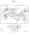
- FIG. 2 shows a configuration example of an ion concentration measuring apparatus 200 on which the cartridge 101 described above is mounted.
- the ion concentration measurement apparatus 200 includes a measurement unit 201, a control unit 202, a calculation recording unit 203, and an output unit 204.
- the measurement unit 201 is connected to a control unit 202, a calculation recording unit 203, and an output unit 204.
- the measurement unit 201 includes a dilution tank 211, a specimen dispensing nozzle 212, a diluent dispensing nozzle 213, an internal standard solution dispensing nozzle 214, a suction nozzle 215, a pipe 216, a sodium ion selective electrode cartridge 217, and a potassium ion selective electrode.
- a cartridge 218, a chloride ion selective electrode cartridge 219, a reference electrode cartridge 220, a pipe 221, a pump 222, a potential measurement unit 223, and an information read / write unit 224 are included.
- the sodium ion selective electrode cartridge 217, the potassium ion selective electrode cartridge 218, the chloride ion selective electrode cartridge 219, and the reference electrode cartridge 220 all have the structure of the cartridge 101 described with reference to FIGS. 1A to 1C. ing.
- the sodium ion selective electrode cartridge 217, the potassium ion selective electrode cartridge 218, the chloride ion selective electrode cartridge 219, and the reference electrode cartridge 220 may be collectively referred to as “cartridge”.
- the cartridge 217, potassium ion selective electrode cartridge 218, and chloride ion selective electrode cartridge 219 may be collectively referred to as “ion selective electrode cartridge”.
- the flow paths 102 (FIGS. 1A to 1C) formed in the sodium ion selective electrode cartridge 217, the potassium ion selective electrode cartridge 218, the chloride ion selective electrode cartridge 219, and the reference electrode cartridge 220 are connected to each other.
- the flow path is formed.
- the pipe 216 is connected to one opening of the flow path 102 of the sodium ion selective electrode cartridge 217, and the pipe 221 is connected to one opening of the flow path 102 of the reference electrode cartridge 220.
- the casing of the measurement unit 201 is electromagnetically shielded. With this electromagnetic shield, the inside of the measurement unit 201 can operate without being affected by electromagnetic noise from the outside.
- the specimen dispensing nozzle 212, the diluent dispensing nozzle 213, and the internal standard liquid dispensing nozzle 214 are used to dispense and discharge the serum specimen, the diluent, and the internal standard liquid to the dilution tank 211, respectively.
- the suction nozzle 215 can move up and down as indicated by arrows in the figure, and can suck the solution in the dilution tank 211 by the driving force of the pump 222.
- the solution sucked from the dilution tank 211 passes through a pipe 216 to a sodium ion selective electrode cartridge 217, a potassium ion selective electrode cartridge 218, a chloride ion selective electrode cartridge 219, a reference electrode cartridge 220, a pipe 221 and a pump 222. And flow. The solution that has passed through the pump 222 is discarded.
- One end of each of the internal electrodes 104 mounted on the sodium ion selective electrode cartridge 217, the potassium ion selective electrode cartridge 218, the chloride ion selective electrode cartridge 219, and the reference electrode cartridge 220 is connected to the potential measuring unit 223. Yes.
- the information read / write unit 224 is disposed in the vicinity of the sodium ion selective electrode cartridge 217, the potassium ion selective electrode cartridge 218, the chloride ion selective electrode cartridge 219, and the reference electrode cartridge 220.
- FIG. 3 shows an operation example when measuring a standard solution.
- FIG. 4 shows a time chart corresponding to the operation example.
- the measurement unit 201 discharges the standard solution to the dilution tank 211 using the sample dispensing nozzle 212 (S301).
- the measurement unit 201 discharges the diluent to the dilution tank 211 using the diluent dispensing nozzle 213 (S302).
- the standard solution is diluted.
- a method in which the standard solution is not diluted with a diluent can also be employed. In that case, the operation of S302 is omitted.
- the measurement unit 201 uses the suction nozzle 215 and the pump 222 to suck the standard solution in the dilution tank 211 (S303). As a result, the channel 102 of the sodium ion selective electrode cartridge 217, the potassium ion selective electrode cartridge 218, the chloride ion selective electrode cartridge 219, and the reference electrode cartridge 220 is filled with the standard solution. Thereafter, the measurement unit 201 uses the potential measurement unit 223 to select an ion selective electrode cartridge based on the reference electrode (sodium ion selective electrode cartridge 217, potassium ion selective electrode cartridge 218, chloride ion selective electrode cartridge). 219) The potential of each electrode is measured.
- the potential difference between the internal electrode 104 of the ion selective electrode cartridge and the internal electrode 104 of the reference electrode cartridge 220 is measured (S304).
- the measurement of the potential is performed in a time-sharing manner for the sodium ion selective electrode cartridge 217, the potassium ion selective electrode cartridge 218, and the chloride ion selective electrode cartridge 219.
- the information read / write unit 224 After measuring the potential, the information read / write unit 224 starts transmitting radio waves (S305). At this time, the measurement unit 201 transmits and receives information to be described later between the IC tag 103 mounted on each cartridge and the information read / write unit 224 (S306). When the transmission / reception of information ends, the measurement unit 201 ends the transmission of radio waves by the information read / write unit 224 (S307).
- the step of measuring the potential of the electrode includes the step of starting transmission of radio waves (S305), the step of transmitting and receiving information (S306), It is independent in time from any of the steps (S307) for terminating transmission. Therefore, the potential measured from each electrode is not affected by the radio waves from the information read / write unit 224 or the IC tag 103, and the potential can be measured with high measurement accuracy. Of course, information related to the device and its use conditions can be recorded in the IC tag 103. Note that the slope sensitivity of each electrode can be obtained from the measured potential by executing the above-described operation of measuring the standard solution for two types of standard solutions.
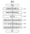
- FIG. 5 shows an operation example when measuring the internal standard solution.
- the measurement unit 201 discharges the internal standard solution to the dilution tank 211 using the internal standard solution dispensing nozzle 214 (S501).
- the measurement unit 201 uses the suction nozzle 215 and the pump 222 to suck the internal standard solution in the dilution tank 211 (S502).
- the flow path 102 of the sodium ion selective electrode cartridge 217, the potassium ion selective electrode cartridge 218, the chloride ion selective electrode cartridge 219, and the reference electrode cartridge 220 is filled with the internal standard solution.
- the measurement unit 201 measures the potential of each electrode based on the reference electrode using the potential measurement unit 223 (S503). After measuring the potential, the information read / write unit 224 starts transmitting radio waves (S504). At this time, information is transmitted and received between the IC tag 103 mounted on each cartridge and the information read / write unit 224 (S505). When the transmission / reception of information ends, the measurement unit 201 ends the transmission of radio waves by the information read / write unit 224 (S506).
- the time chart corresponding to this operation example is the same as that in FIG. 4, and the main difference is that a step of discharging the internal standard solution is employed instead of the steps of discharging the standard solution and discharging the diluent. .
- the concentration of each ion contained in the internal standard solution is determined from the potential obtained as a result of the above operation for measuring the internal standard solution, the slope sensitivity, and the potential of the standard solution.
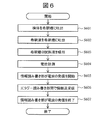
- FIG. 6 shows an operation example when measuring a specimen.
- the measurement unit 201 discharges the sample to the dilution tank 211 using the sample dispensing nozzle 212 (S601).
- the measurement unit 201 discharges the diluent to the dilution tank 211 using the diluent dispensing nozzle 213 (S602).
- the specimen is diluted.
- a method in which the specimen is not diluted with a diluent can also be employed. In that case, the operation of S602 is omitted.
- the measurement unit 201 uses the suction nozzle 215 and the pump 222 to suck the sample liquid in the dilution tank 211 (S603).
- the flow path 102 of the sodium ion selective electrode cartridge 217, the potassium ion selective electrode cartridge 218, the chloride ion selective electrode cartridge 219, and the reference electrode cartridge 220 is filled with the sample solution containing the specimen.
- the measurement unit 201 measures the potential of each electrode based on the reference electrode using the potential measurement unit 223 (S604).
- the information read / write unit 224 starts transmitting radio waves (S605).
- information is transmitted and received between the IC tag 103 mounted on each cartridge and the information read / write unit 224 (S606).
- the information read / write unit 224 ends the transmission of radio waves (S607).
- the time chart in this case is the same as that in FIG. 4, and the main difference is that a step of discharging the specimen is adopted instead of the step of discharging the standard solution.
- the concentration of each ion in the sample can be obtained from the potential obtained as a result of the above-described measurement of the sample, the slope sensitivity, the potential and concentration of the internal standard solution, and the dilution rate as necessary. .
- FIG. 7 shows an operation example when each measurement is continuously performed.
- the measurement unit 201 measures an internal standard solution (S701).
- This S701 corresponds to the process shown in FIG.
- the measurement unit 201 measures the standard solution (S702).
- This S702 corresponds to the process shown in FIG.
- the measurement unit 201 measures the internal standard solution (S703).
- This S703 also corresponds to the process shown in FIG.
- the measurement unit 201 performs sample measurement (S704).
- This S704 corresponds to the process shown in FIG.
- the measurement unit 201 measures the internal standard solution (S705).
- This S705 also corresponds to the process shown in FIG.
- the information of the nth measurement may be transmitted / received before the (n + 1) th measurement. Further, information may be transmitted and received during an idle time (standby time) corresponding to a timing at which a series of measurements are interrupted.
- Operation example 5 (other examples of transmission / reception timing)
- the timing of transmission / reception of information is not limited after the measurement of the standard solution, the internal standard solution and the sample as in the operation examples 1 to 3, and may be any time as long as the potential measurement period and the radio wave transmission period do not overlap.
- the transmission of radio waves may be executed before the potential measurement, or the radio waves may be transmitted in parallel with the potential measurement pretreatment (solution discharge / suction) as shown in FIGS. Transmission may be executed.
- Example of Information Concerning Measurement of Ion Concentration Information stored in the IC tag 103 includes ion type, lot number, serial number, expiration date, and date of manufacture, which are electrode-specific information determined at the time of manufacture.
- time profiles such as temperature, humidity, atmospheric pressure, acceleration, etc., which are information at the time of transportation and storage, and measurement facilities, measuring devices, measurement personnel that are information acquired or updated for each measurement Person, measurement channel, measurement date and time, type and composition of used reagent (standard solution, dilution solution), pH, reaction time, stirring time, sample aliquot, dilution solution amount, dilution rate, introduction solution amount, introduction time, Introduction flow rate, introduction flow rate, temperature, humidity, pressure, measurement cycle time, measurement waiting time, data acquisition time, number of data acquisitions, potential, concentration of each ion that is the measurement result, electrode resistance and impedance And measurement sample number, slope sensitivity, potential stability, simultaneous reproducibility, selectivity, correction coefficient, time response characteristics,
- information that can identify the electrode such as at least a serial number
- information that can identify the electrode is read from the IC tag 103 among the information unique to the electrode.
- information at the time of transportation storage is also possible to read out information at the time of transportation storage as necessary.
- Information acquired or updated for each measurement is written to the IC tag 103 as needed.
- specific information, information at the time of transportation and storage, and information acquired or updated for each measurement can be read from the collected IC tag 103 of the cartridge 101, and these can be used as improved information of the ion concentration measuring apparatus.
- FIG. 11 shows a configuration example of an ion concentration measurement apparatus 1100 used in this embodiment.
- the ion concentration measuring apparatus 1100 basically has the same configuration as that of the first embodiment, but differs in the following points.
- the first difference is that the reference electrode cartridge 220 (second cartridge) is separated from the ion selective electrode cartridge (first cartridge).
- the ion selective electrode cartridge corresponds to a sodium ion selective electrode cartridge 217, a potassium ion selective electrode cartridge 218, and a chloride ion selective electrode cartridge 219.
- the chloride ion selective electrode cartridge 219 and the reference electrode cartridge 220 are connected via a pipe 1111, a valve 1112, a junction 1113, and a pipe 1114 in this order.
- a pump 222 is connected to the junction 1113 through a pipe 221.
- the second difference is that a supply flow path for the reference liquid 1119 is connected to the reference electrode cartridge 220.
- This supply flow path includes a pipe 1115, a valve 1116, and a pipe 1117.
- the reference liquid 1119 is stored in the reference liquid container 1118.
- the opening and closing of the valves 1112 and 1116 is controlled by the control unit 202.
- the sample dispensing nozzle 212 dispenses and discharges the serum sample to the dilution tank 211
- the diluent dispensing nozzle 213 dispenses and discharges the dilution liquid to the dilution tank 211, and the internal standard solution dispensing nozzle.
- 214 dispenses and discharges the internal standard solution to the dilution tank 211.
- the suction nozzle 215 can move up and down, and the solution in the dilution tank 211 can be sucked by the driving force of the pump 222.
- valve 1112 When the valve 1112 is opened and the valve 1116 is closed, the solution sucked by the driving of the pump 222 is introduced into the flow path of the ion selective electrode cartridge through the pipe 216, and further through the pipe 1111, the junction 1113, and the pipe 221. Discarded.
- the valve 1112 when the valve 1112 is closed and the valve 1116 is opened, the reference liquid 1119 is sucked through the pipe 1117 by driving the pump 222 and introduced into the flow path 102 of the reference electrode cartridge 220, and further, the pipe 1114, the junction 1113, It is discarded through the pipe 221.
- the information read / write unit 224 is disposed in the vicinity of the sodium ion selective electrode cartridge 217, the potassium ion selective electrode cartridge 218, the chloride ion selective electrode cartridge 219, and the reference electrode cartridge 220.
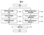
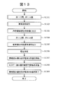
- FIG. 12 shows an operation example when measuring a standard solution.
- the measurement unit 1101 closes the valve 1112 and opens the valve 1116 (S1201).
- the measurement unit 1101 sucks the reference liquid 1119 from the reference liquid container 1118 using the pump 222 (S1202).
- the channel 102, the pipe 1114, and the junction 1113 of the reference electrode cartridge 220 are filled with the reference liquid 1119.
- the measurement unit 1101 discharges the standard solution to the dilution tank 211 using the sample dispensing nozzle 212 (S1203).
- the diluent is discharged into the dilution tank 211 using the diluent dispensing nozzle 213 (S1204).
- the standard solution is diluted.
- a method in which the standard solution is not diluted with a diluent can also be employed. In that case, the operation of S1204 is omitted.
- the measurement unit 1101 opens the valve 1112 and closes the valve 1116 (S1205).
- the measurement unit 1101 sucks the standard solution in the dilution tank 211 using the suction nozzle 215 and the pump 222 (S1206).
- the sodium ion selective electrode cartridge 217, the potassium ion selective / BR> electrode cartridge 218, the flow path 102, the piping 1111 and the junction 1113 of the chloride ion selective electrode cartridge 219 are filled with the standard solution.
- the ion selective electrode cartridge and the reference electrode cartridge 220 are connected to each other by pipes 1111 and 1114 filled with a solution and a junction 1113. Therefore, the measurement unit 1101 can measure the potential of each electrode of the ion selective electrode cartridge based on the reference electrode using the potential measurement unit 223 (S1207). The measurement of the potential is performed in a time-sharing manner for the sodium ion selective electrode cartridge 217, the potassium ion selective electrode cartridge 218, and the chloride ion selective electrode cartridge 219.
- the information read / write unit 224 After measuring the potential, the information read / write unit 224 starts transmitting radio waves (S1208). At this time, the measurement unit 1101 transmits and receives information between the IC tag 103 mounted on each cartridge and the information read / write unit 224 (S1209). When the transmission / reception of information ends, the measurement unit 1101 ends the transmission of radio waves by the information read / write unit 224 (S1210). Note that the slope sensitivity of each electrode can be obtained from the measured potential by executing the above-described operation of measuring the standard solution for two types of standard solutions.
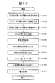
- FIG. 13 shows an operation example when measuring the internal standard solution.
- the measurement unit 1101 closes the valve 1112 and opens the valve 1116 (S1301).
- the measuring unit 1101 sucks the reference liquid 1119 from the reference liquid container 1118 using the pump 222 (S1302).
- the channel 102, the pipe 1114, and the junction 1113 of the reference electrode cartridge 220 are filled with the reference liquid 1119.
- the measurement unit 1101 discharges the internal standard solution to the dilution tank 211 using the internal standard solution dispensing nozzle 214 (S1103). Thereby, the internal standard solution is diluted.
- the measurement unit 1101 opens the valve 1112 and closes the valve 1116 (S1304).
- the measurement unit 1101 sucks the internal standard solution in the dilution tank 211 using the suction nozzle 215 and the pump 222 (S1305).
- the flow path 102, the piping 1111 and the junction 1113 of the sodium ion selective electrode cartridge 217, the potassium ion selective electrode cartridge 218, and the chloride ion selective electrode cartridge 219 are filled with the internal standard solution.
- the ion selective electrode cartridge and the reference electrode cartridge 220 are connected to each other by pipes 1111 and 1114 filled with a solution and a junction 1113. Therefore, the measurement unit 1101 can measure the potential of each electrode of the ion selective electrode cartridge with reference to the reference electrode using the potential measurement unit 223 (S1306).
- the information read / write unit 224 After measuring the potential, the information read / write unit 224 starts transmitting radio waves (S1307). At this time, the measurement unit 1101 transmits and receives information between the IC tag 103 mounted on each cartridge and the information read / write unit 224 (S1308). When the transmission / reception of information ends, the information read / write unit 224 ends the transmission of radio waves (S1309).
- the concentration of each ion contained in the internal standard solution is determined from the potential obtained as a result of the above operation for measuring the internal standard solution, the slope sensitivity, and the potential of the standard solution.
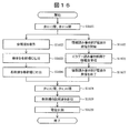
- FIG. 14 shows an operation example when measuring a specimen.
- the measurement unit 1101 closes the valve 112 and opens the valve 1116 (S1401).
- the measurement unit 1101 aspirates the reference liquid 1119 from the reference liquid container 1118 using the pump 222 (S1402).
- the channel 102, the pipe 1114, and the junction 1113 of the reference electrode cartridge 220 are filled with the reference liquid 1119.
- the measurement unit 1101 discharges the sample to the dilution tank 211 using the sample dispensing nozzle 212 (S1403).
- the measurement unit 1101 discharges the diluent to the dilution tank 211 using the diluent dispensing nozzle 213 (S1404). Thereby, the specimen is diluted.
- a method in which the specimen is not diluted with a diluent can also be employed. In that case, the operation of S1404 is omitted.
- the measurement unit 1101 opens the valve 1112 and closes the valve 1116 (S1405).
- the measurement unit 1101 sucks the sample liquid in the dilution tank 211 using the suction nozzle 215 and the pump 222 (S1406).
- the channel 102, the piping 1111 and the junction 1113 of the sodium ion selective electrode cartridge 217, the potassium ion selective electrode cartridge 218, and the chloride ion selective electrode cartridge 219 are filled with the sample solution containing the specimen.
- the ion selective electrode cartridge and the reference electrode cartridge 220 are connected to each other by pipes 1111 and 1114 filled with a solution and a junction 1113. Therefore, the measurement unit 1101 can measure the potential of each electrode of the ion selective electrode cartridge based on the reference electrode using the potential measurement unit 223 (S1407).
- the information read / write unit 224 After measuring the potential, the information read / write unit 224 starts transmitting radio waves (S1408). At this time, the measurement unit 1101 transmits / receives information between the IC tag 103 mounted on each cartridge and the information read / write unit 224 (S1409). When the transmission / reception of information ends, the information read / write unit 224 ends the transmission of radio waves (S1410).
- the concentration of each ion in the sample can be obtained from the potential obtained as a result of the above-described measurement of the sample, the slope sensitivity, the potential and concentration of the internal standard solution, and the dilution rate as necessary. .
- (3-2-4) Operation example 4 (other examples of transmission timing)
- the timing of transmission / reception of information is not limited after measurement of standard solution, internal standard solution, and specimen as in operation examples 1 to 3, but the potential measurement period, radio wave transmission period, and valve opening / closing period If it does not overlap, it is always good.
- the transmission of radio waves may be executed before the potential measurement, or the transmission of radio waves is executed in parallel with the potential measurement pretreatment (solution discharge / suction) as shown in FIG.
- the period, the valve opening / closing period, and the potential measurement period may be set so as not to overlap each other.
- valve opening / closing period and the potential measurement period do not overlap each other is to prevent the induced current generated by the mechanical operation of the valve from affecting communication.
- 15 and 16 illustrate the case of measuring a standard solution, but the same applies to the case of measuring an internal standard solution or a sample instead of the standard solution.
- Examples 4-1 and 2 described above serum was used as an example of a specimen to be measured, but blood, plasma, spinal fluid, urine, gastric juice, Examples include biological solutions such as intestinal fluid, bile, saliva, tears, and other body fluids such as cell extracts, dialysis fluids, infusions, nutrients, medical solutions, and other medical solutions. It can be measured with the same configuration and procedure.
- Electromagnetic shield In the first and second embodiments described above, the case where the electromagnetic shield is applied to the casing of the measurement unit has been described. This is for the purpose of suppressing the influence of external electromagnetic noise.
- a case where one measurement unit is mounted on one ion concentration measurement device is described. However, a plurality of measurements are performed on one ion concentration measurement device. A case where a unit is installed is also assumed. It is also assumed that an ion concentration measuring device is incorporated as part of the biochemical automatic analyzer. In these cases, electromagnetic noise from other adjacent measurement units may adversely affect the reading / writing of information between the information reading / writing unit 224 and the IC tag 103.
- the ion concentration measuring device is installed mainly in clinical laboratory departments and inspection centers of medical institutions, and there may be many measuring devices other than the ion concentration measuring device. For this reason, there is a possibility that a lot of electromagnetic noise is generated from these other measuring devices and IC tags attached to the measuring devices. Furthermore, with the recent automation of clinical tests, there are many cases where RFID tags are attached to sample containers such as blood collection tubes, urine collection tubes, and test tubes, and electromagnetic noise from these tags may not be negligible. .
- the electromagnetic shield only needs to suppress electromagnetic noise that adversely affects the reading and writing of information with the IC tag 103.
- a metal plate, a wire mesh, a metal film, metal spraying, conductive coating, conductive plastic, or the like can be used.
- the IC tag 103 may be mounted only on the ion selective electrode cartridge. Further, as shown in FIG. 17, the IC tag 103 may be mounted on a reagent container 1701 that stores an internal standard solution, a diluted solution, a reference solution, and the like. When the IC tag 103 is mounted on both the cartridge 101 and the reagent container 1701, only one information read / write unit 224 may be mounted on the ion concentration measuring device 1100 as shown in FIG. Two of them may be mounted as shown in the concentration measuring apparatus 1600. Note that the mounting positions of the information read / write units 224A and 224B are arbitrary.
- FIG. 19 shows an example of the cartridge 101 corresponding to the wired communication system.
- the cartridge 101 includes two terminals 1901 and 1902.
- a terminal 1901 is for reading / writing information from / to the IC tag 103A
- a terminal 1902 is for measuring a potential.
- the IC tag 103A includes a semiconductor memory 1903 and a transceiver 1904. Reading / writing information to / from the IC tag 103A is performed through the transceiver 1904 on the information reading / writing unit 224 side.
- the output signal of the internal electrode 104 is amplified by an amplifier 1905 connected to a terminal 1902 and supplied to the potential measuring unit 223.
- FIG. 20 shows another example of the cartridge 101 corresponding to the wired communication system.
- the cartridge 101 has only one terminal 2001. That is, in the cartridge 101 illustrated in FIG. 20, reading and writing of information (digital signal) and reading of the output signal (analog signal) of the internal electrode 104 are performed in a time-sharing manner through one terminal 2001. A signal path used for reading and writing information (digital signal) and a signal path of an output signal of the internal electrode 104 are separated by a capacitor 2002. Since the frequency component of the information (digital signal) is high, it can pass through the capacitor 2002. However, the output signal (analog signal) of the internal electrode 104 is basically a direct current component and cannot pass through the capacitor 2002.
- the two signal paths are separated by a capacitor 2003.
- an amplifier 2004 is connected on the signal path on the internal electrode 104 side. This is because a sufficiently large output signal (analog signal) is output to the terminal 2001.
- the ion concentration measuring apparatus in Examples 1 and 2 described above is not limited to the above-described measurement of the concentration of ionic species, but can be used to measure the concentration of any ion species. Can be applied.
- the above-described configurations, functions, processing units, processing means, and the like may be realized by hardware by designing a part or all of them with, for example, an integrated circuit.
- Each of the above-described configurations, functions, and the like may be realized by the processor interpreting and executing a program that realizes each function (that is, in software).
- Information such as programs, tables, and files that realize each function can be stored in a storage device such as a memory, a hard disk, or an SSD (Solid State Drive), or a storage medium such as an IC card, an SD card, or a DVD.
- Control lines and information lines indicate what is considered necessary for the description, and do not represent all control lines and information lines necessary for the product. In practice, it can be considered that almost all components are connected to each other.
- Chloride ion selective electrode cartridge 220 ... Reference electrode cartridge 222 ... Pump 223 ... Potential measurement unit 224, 224A, 224B ... Information read / write unit 1112, 1116 ... Valve 1113 ... Junction 1118 ... Reference solution Container 1 19 ... reference liquid 1701 ... reagent container 1901,1902,2001 ... terminal 1903 ... semiconductor memory 1904 ... transceivers 1905,2004 ... amplifier 2002 and 2003 ... capacitor
Abstract
Description
まず、イオン濃度測定装置に搭載されるイオン選択性電極のカートリッジの構成例を説明する。本実施例の場合、カートリッジは、イオン濃度測定装置の装置本体に対してユーザが着脱自在に装着できるものとする。従って、イオン濃度測定装置が故障した場合、ユーザは装置本体からカートリッジを取り外し、別のイオン濃度測定装置に装着することができる。もっとも、カートリッジは、専門家によるメンテナンス作業以外では、イオン濃度測定装置から取り外すことができないように設計されていても良い。 (1) Cartridge Configuration First, a configuration example of an ion selective electrode cartridge mounted on an ion concentration measuring apparatus will be described. In the case of the present embodiment, it is assumed that the cartridge can be detachably attached to the apparatus main body of the ion concentration measuring apparatus. Therefore, when the ion concentration measuring device fails, the user can remove the cartridge from the device main body and attach it to another ion concentration measuring device. However, the cartridge may be designed so that it cannot be removed from the ion concentration measuring apparatus except for maintenance work by an expert.
(2-1)装置の全体構成
図2に、前述したカートリッジ101を搭載するイオン濃度測定装置200の構成例を示す。イオン濃度測定装置200は、測定ユニット201、制御部202、演算記録部203、出力部204を有している。測定ユニット201には、制御部202、演算記録部203、出力部204が接続されている。 (2) Example 1
(2-1) Overall Configuration of Apparatus FIG. 2 shows a configuration example of an ion
以下、イオン濃度測定装置200において実行される動作を説明する。後述する各フローチャートは、制御部202によってコントロールされる測定ユニット201の動作を示している。 (2-2) Operation Example Hereinafter, an operation executed in the ion
図3に、標準溶液を測定する場合の動作例を示す。図4に、その動作例に対応するタイムチャートを示す。まず、測定ユニット201が、検体分注ノズル212を用いて標準溶液を希釈槽211に吐出する(S301)。次に、測定ユニット201は、希釈液分注ノズル213を用いて希釈液を希釈槽211に吐出する(S302)。これにより、標準溶液が希釈される。なお、希釈液で標準溶液を希釈しない方法も採用できる。その場合、S302の動作は省略する。 (2-2-1) Operation example 1 (standard solution measurement)
FIG. 3 shows an operation example when measuring a standard solution. FIG. 4 shows a time chart corresponding to the operation example. First, the
図5に、内部標準液を測定する場合の動作例を示す。まず、測定ユニット201は、内部標準液分注ノズル214を用いて内部標準液を希釈槽211に吐出する(S501)。次に、測定ユニット201は、吸引ノズル215とポンプ222を用い、希釈槽211内の内部標準液を吸引する(S502)。これにより、ナトリウムイオン選択性電極カートリッジ217、カリウムイオン選択性電極カートリッジ218、塩化物イオン選択性電極カートリッジ219、参照電極カートリッジ220の流路102は内部標準液で満たされる。 (2-2-2) Operation example 2 (measurement of internal standard solution)
FIG. 5 shows an operation example when measuring the internal standard solution. First, the
図6に、検体を測定する場合の動作例を示す。まず、測定ユニット201は、検体分注ノズル212を用いて検体を希釈槽211に吐出する(S601)。次に、測定ユニット201は、希釈液分注ノズル213を用いて希釈液を希釈槽211に吐出する(S602)。これにより、検体が希釈される。なお、希釈液で検体を希釈しない方法も採用できる。その場合、S602の動作は省略する。 (2-2-3) Operation example 3 (specimen measurement)
FIG. 6 shows an operation example when measuring a specimen. First, the
動作例1~3では、標準溶液、内部標準液および検体の測定を別々に行ったが、これらの測定を一連の流れとして実行することもできる。図7に、連続的に各測定を実行する場合の動作例を示す。まず、測定ユニット201は、内部標準液の測定(S701)を行う。このS701は、図5に示す工程に対応する。続いて、測定ユニット201は、標準溶液の測定(S702)を行う。このS702は、図3に示す工程に対応する。その後、測定ユニット201は、内部標準液の測定(S703)を行う。このS703も、図5に示す工程に対応する。続いて、測定ユニット201は、検体の測定(S704)を行う。このS704は、図6に示す工程に対応する。さらに、測定ユニット201は、内部標準液の測定(S705)を行う。このS705も図5に示す工程に対応する。 (2-2-4) Operation example 4 (continuous measurement)
In the operation examples 1 to 3, the measurement of the standard solution, the internal standard solution, and the specimen was performed separately, but these measurements can also be executed as a series of flows. FIG. 7 shows an operation example when each measurement is continuously performed. First, the
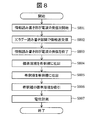
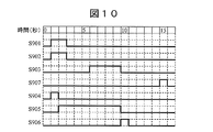
情報の送受信のタイミングは、動作例1~3のように、標準溶液、内部標準液および検体の測定後に限定されるものではなく、電位の測定期間と電波発信期間とが重ならなければいつでも良い。例えば図8に示すように電位の測定前に電波の発信を実行しても良いし、図9や図10に示すように電位測定の前処理(溶液の吐出/吸引)と並列して電波の発信を実行しても良い。 (2-2-5) Operation example 5 (other examples of transmission / reception timing)
The timing of transmission / reception of information is not limited after the measurement of the standard solution, the internal standard solution and the sample as in the operation examples 1 to 3, and may be any time as long as the potential measurement period and the radio wave transmission period do not overlap. . For example, as shown in FIG. 8, the transmission of radio waves may be executed before the potential measurement, or the radio waves may be transmitted in parallel with the potential measurement pretreatment (solution discharge / suction) as shown in FIGS. Transmission may be executed.
ICタグ103に格納する情報には、製造時に決定付けられる電極固有の情報であるイオンの種類、ロット番号、シリアル番号、有効期限、製造日、適正出力範囲、警報条件などの他、輸送保管時の情報である温度、湿度、気圧、加速度などの時間プロファイル、また測定毎に取得または更新される情報である測定施設、測定装置、測定担当者、測定チャンネル、測定日時、使用した試薬(標準溶液、希釈液)の種類及び組成、pH、反応時間、撹拌時間、試料分取量、希釈液量、希釈倍率、導入液量、導入時間、導入流量、導入流速、温度、湿度、圧力、測定サイクル時間、測定待ち時間、データ取得時間、データ取得回数、電位、測定結果である各イオンの濃度、電極の抵抗やインピーダンス、測定試料数、スロープ感度、電位安定性、同時再現性、選択性、補正係数、時間応答特性、感度、検量線再測定条件、データ処理アルゴリズム、交換パーツの情報等がある。 (2-3) Example of Information Concerning Measurement of Ion Concentration Information stored in the
ここでは、カートリッジ101の製造時からその回収までに実行される情報の読み書き動作例を説明する。まず、カートリッジ101の製造時、電極固有の情報をICタグ103に書き込む。その後、流通業者や倉庫業者などから提供される輸送保管時の情報を、各時点で、ICタグ103に書き込む。なお、輸送保管時の情報は、流通業者や倉庫業者が、カートリッジ101に搭載されるICタグ103とは別のICタグ(例えば流通過程で使用する流通箱、コンテナ、トラック、船、飛行機などに搭載される)から収集することが可能である。 (2-4) Information Reading / Writing Operation Example Here, an example of information reading / writing operation executed from the time of manufacture of the
本実施例に係るイオン濃度測定装置200を用いれば、高い測定精度を損なうことなく、機器や使用条件などに関連する情報をICタグ103に記録し、又は読み出すことができる。また、イオン濃度の測定期間(電位差の測定期間)以外は、ICタグ103との情報の読み書きに利用できるため、測定作業の効率化を図ることができる。さらに、頻繁に情報を更新することが可能なため、常に最新の情報を取得して装置運用へ反映させることができる。 (2-5) Summary By using the ion
(3-1)装置の全体構成
図11に、本実施例で使用するイオン濃度測定装置1100の構成例を示す。図11には、図2との対応部分に同一符号を付して示す。イオン濃度測定装置1100は、基本的に実施例1と同様の構成を有しているが、以下の点で異なっている。 (3) Example 2
(3-1) Overall Configuration of Apparatus FIG. 11 shows a configuration example of an ion
以下、イオン濃度測定装置1100において実行される動作を説明する。後述する各フローチャートは、制御部202によってコントロールされる測定ユニット1101の動作を示している。 (3-2) Operation Example Hereinafter, an operation executed in the ion
図12に、標準溶液を測定する場合の動作例を示す。まず、測定ユニット1101は、弁1112を閉じ、弁1116を開ける(S1201)。次に、測定ユニット1101は、ポンプ222を用いて参照液1119を参照液容器1118から吸引する(S1202)。これにより、参照電極カートリッジ220の流路102、配管1114、ジャンクション1113は参照液1119で満たされる。この後、測定ユニット1101は、検体分注ノズル212を用いて標準溶液を希釈槽211に吐出する(S1203)。続いて、希釈液分注ノズル213を用いて希釈液を希釈槽211に吐出する(S1204)。これにより、標準溶液が希釈される。なお、希釈液で標準溶液を希釈しない方法も採用できる。その場合、S1204の動作は省略する。 (3-2-1) Operation example 1 (measurement of standard solution)
FIG. 12 shows an operation example when measuring a standard solution. First, the
図13に、内部標準液を測定する場合の動作例を示す。まず、測定ユニット1101が、弁1112を閉じ、弁1116を開ける(S1301)。次に、測定ユニット1101は、ポンプ222を用いて参照液1119を参照液容器1118から吸引する(S1302)。これにより、参照電極カートリッジ220の流路102、配管1114、ジャンクション1113は参照液1119で満たされる。この後、測定ユニット1101は、内部標準液分注ノズル214を用いて内部標準液を希釈槽211に吐出する(S1103)。これにより、内部標準液が希釈される。 (3-2-2) Operation example 2 (Measurement of internal standard solution)
FIG. 13 shows an operation example when measuring the internal standard solution. First, the
図14に、検体を測定する場合の動作例を示す。まず、測定ユニット1101が、弁112を閉じ、弁1116を開ける(S1401)。次に、測定ユニット1101は、ポンプ222を用いて参照液1119を参照液容器1118から吸引する(S1402)。これにより、参照電極カートリッジ220の流路102、配管1114、ジャンクション1113は参照液1119で満たされる。この後、測定ユニット1101は、検体分注ノズル212を用いて検体を希釈槽211に吐出する(S1403)。続いて、測定ユニット1101は、希釈液分注ノズル213を用いて希釈液を希釈槽211に吐出する(S1404)。これにより、検体が希釈される。なお、希釈液で検体を希釈しない方法も採用できる。その場合、S1404の動作は省略する。 (3-2-3) Operation example 3 (specimen measurement)
FIG. 14 shows an operation example when measuring a specimen. First, the
情報の送受信のタイミングは、動作例1~3のように、標準溶液、内部標準液および検体の測定後に限定されるものではなく、電位の測定期間と、電波発信期間や弁の開閉期間とが重ならなければいつでも良い。例えば図15に示すように電位の測定前に電波の発信を実行しても良いし、図16に示すように電位測定の前処理(溶液の吐出/吸引)と並列して電波の発信を実行すると共に、それら期間と弁の開閉期間と電位の測定期間とが互いに重ならないように設定しても良い。ここで、弁の開閉期間と電位の測定期間とが重ならないようにするのは、弁の機械的動作に伴って発生する誘導電流が通信に影響を及ぼさないようにするためである。図15および図16では、標準溶液を測定する場合を例示したが、標準溶液に代えて内部標準液や検体を測定する場合でも同様である。 (3-2-4) Operation example 4 (other examples of transmission timing)
The timing of transmission / reception of information is not limited after measurement of standard solution, internal standard solution, and specimen as in operation examples 1 to 3, but the potential measurement period, radio wave transmission period, and valve opening / closing period If it does not overlap, it is always good. For example, as shown in FIG. 15, the transmission of radio waves may be executed before the potential measurement, or the transmission of radio waves is executed in parallel with the potential measurement pretreatment (solution discharge / suction) as shown in FIG. In addition, the period, the valve opening / closing period, and the potential measurement period may be set so as not to overlap each other. Here, the reason why the valve opening / closing period and the potential measurement period do not overlap each other is to prevent the induced current generated by the mechanical operation of the valve from affecting communication. 15 and 16 illustrate the case of measuring a standard solution, but the same applies to the case of measuring an internal standard solution or a sample instead of the standard solution.
動作例1~3では、標準溶液、内部標準液および検体の測定を別々に行ったが、これらの測定を実施例1の場合と同様に一連の流れとして実行することもできる。この場合、n番目の測定の情報はn+1番目の測定の前に送受信を行うことも可能である。また、一連の測定が途切れるタイミングにあたるアイドルタイム(待機時間)に情報を送受信することもできる。 (3-2-5) Operation example 5 (continuous measurement)
In the operation examples 1 to 3, the measurement of the standard solution, the internal standard solution, and the specimen were performed separately, but these measurements can also be executed as a series of flows as in the case of the first embodiment. In this case, the information of the nth measurement can be transmitted and received before the (n + 1) th measurement. In addition, information can be transmitted and received during idle time (standby time) corresponding to the timing at which a series of measurements are interrupted.
本実施例に係るイオン濃度測定装置1100を用いれば、高い測定精度を損なうことなく、機器やその使用条件などに関連する情報をICタグ103に記録し、又は読み出すことができる。また、イオン濃度の測定期間(各電極の電位の測定期間)や弁の開閉期間以外は、ICタグ103との情報の読み書きに利用できるため、測定作業の効率化を図ることができる。さらに、頻繁に情報を更新することが可能なため、常に最新の情報を取得して装置運用へ反映させることができる。 (3-3) Summary By using the ion
(4-1)検体
前述の実施例1及び2においては、測定対象とする検体の例として血清を用いたが、他に血液、血漿、髄液、尿、胃液、腸液、胆汁、唾液、涙等の体液や細胞抽出液などの生体に由来する溶液、透析液、輸液、栄養剤、薬剤などの医療に用いる溶液等もあげられ、これらの溶液は血清の測定と同様の構成、手順で測定することができる。 (4) Other Examples (4-1) Specimens In Examples 1 and 2 described above, serum was used as an example of a specimen to be measured, but blood, plasma, spinal fluid, urine, gastric juice, Examples include biological solutions such as intestinal fluid, bile, saliva, tears, and other body fluids such as cell extracts, dialysis fluids, infusions, nutrients, medical solutions, and other medical solutions. It can be measured with the same configuration and procedure.
前述の実施例1及び2においては、測定ユニットの筐体に電磁シールドを施す場合について説明した。これは、外部からの電磁ノイズの影響を抑制することが目的である。なお、実施例1及び2においては、1台のイオン濃度測定装置に対して1台の測定ユニットを搭載する場合について説明しているが、1台のイオン濃度測定装置に対して複数台の測定ユニットを設置する場合も想定される。また、生化学自動分析装置の一部としてイオン濃度測定装置を組み込む場合も想定される。これらの場合、近接する他の測定ユニットからの電磁ノイズが、情報読み書き部224とICタグ103との情報の読み書きに悪影響を及ぼすおそれがある。 (4-2) Electromagnetic shield In the first and second embodiments described above, the case where the electromagnetic shield is applied to the casing of the measurement unit has been described. This is for the purpose of suppressing the influence of external electromagnetic noise. In the first and second embodiments, a case where one measurement unit is mounted on one ion concentration measurement device is described. However, a plurality of measurements are performed on one ion concentration measurement device. A case where a unit is installed is also assumed. It is also assumed that an ion concentration measuring device is incorporated as part of the biochemical automatic analyzer. In these cases, electromagnetic noise from other adjacent measurement units may adversely affect the reading / writing of information between the information reading /
前述の実施例1及び2においては、いずれも各カートリッジにICタグ103を搭載する例ついて説明したが、イオン選択性電極カートリッジにのみ搭載しても良い。また、図17に示すように、内部標準液、希釈液、参照液などを格納する試薬容器1701にICタグ103を搭載しても良い。カートリッジ101と試薬容器1701の両方にICタグ103を搭載する場合、情報読み書き部224は、図11に示すようにイオン濃度測定装置1100に1つのみ搭載しても良いし、図18に示すイオン濃度測定装置1600に示すように2つ搭載しても良い。なお、情報読み書き部224A及び224Bの搭載位置は任意である。 (4-3) IC Tag Mounting Location In each of the first and second embodiments, the example in which the
前述の実施例1及び2においては、イオン濃度測定装置を単独で使用する場合について説明したが、ICタグ103を構成する半導体メモリを、インターネット上のドライブとして管理可能としても良い。 (4-4) Internet connection In the foregoing first and second embodiments, the case where the ion concentration measuring device is used alone has been described. However, the semiconductor memory constituting the
前述の実施例1及び2においては、測定ユニット内に専用の情報読み書き部を配置する場合について説明したが、例えばスマートフォン、タブレット端末などの汎用の携帯情報処理装置を搭載しても良い。汎用の携帯情報処理装置は、測定ユニットに対して固定ではなく着脱可能な状態にしておくことも可能である。 (4-5) Information read /
In the first and second embodiments described above, the case where the dedicated information read / write unit is arranged in the measurement unit has been described. However, for example, a general-purpose portable information processing device such as a smartphone or a tablet terminal may be mounted. The general-purpose portable information processing apparatus can be fixed to the measurement unit instead of being fixed.
前述の実施例1及び2においては、ICタグ103を構成する半導体メモリが読み書き可能であるため、イオン濃度の測定に関わる情報をICタグ103に対して読み書きする情報読み書き部224を測定ユニットに搭載した。しかし、ICタグ103として想定される半導体メモリがROMである場合には、測定ユニット内に情報読み取り部のみを配置すれば良い。また、測定ユニットには、情報の読み取り専用の情報読み取り部(装置)の他に、情報の書き込み専用の情報書き込み部(装置)を別途搭載しても良い。 (4-6) Information read / write unit 2
In the first and second embodiments described above, since the semiconductor memory constituting the
前述の実施例1及び2においては、情報読み書き部224がICタグ103と電波を発する(すなわち、無線通信方式により通信する)場合について説明した。しかし、電気接点を有する有線通信方式のICタグ103を使用し、情報読み書き部224との通信を有線通信方式で行っても良い。 (4-7) Wired Communication Method In the first and second embodiments, the case where the information read /
前述の実施例1及び2においては、「情報を読み書きするタイミング」と「内部電極104の電位を測定するタイミング」が互いに重ならないようにして(すなわち、時間分割通信方式により)、測定結果へのノイズの混入の抑制を図っている。しかし、時間分割通信方式に加えて、周波数分割方式、信号レベルの違いによる分割方式、符号分割方式を組み合わせることができる。勿論、通信帯域を分割多重化して送信し、受信後に分離する方法(通信帯域の分割多重化方式)も可能である。上記のような方法を組み合わせることで、ノイズの混入を限りなく低レベルに抑制することが可能となる。 (4-8) Noise suppression method other than time division method In the first and second embodiments described above, the “timing for reading / writing information” and the “timing for measuring the potential of the
前述の実施例1及び2におけるイオン濃度測定装置は、前述したイオン種の濃度の測定に限定されることはなく、任意のイオン種の濃度の測定に適用することができる。 (4-9) Ion Species to be Measured The ion concentration measuring apparatus in Examples 1 and 2 described above is not limited to the above-described measurement of the concentration of ionic species, but can be used to measure the concentration of any ion species. Can be applied.
本発明は上記した実施例に限定されるものではなく、様々な変形例が含まれる。上記した実施例は本発明を分かりやすく説明するために詳細に説明したものであり、必ずしも説明した全ての構成を備えるものに限定されるものではない。また、実施例の一部を削除すること、他の実施例の構成と置き換えること、他の実施例の構成を追加することもできる。 (4-10) Others The present invention is not limited to the embodiments described above, and includes various modifications. The above-described embodiments have been described in detail for easy understanding of the present invention, and are not necessarily limited to those having all the configurations described. In addition, it is possible to delete a part of the embodiment, replace the configuration of another embodiment, and add the configuration of another embodiment.
102…流路
103、103A…ICタグ
104…内部電極
105…内部液
106…感応膜
106A…参照電極膜
201、1101…測定ユニット
202…制御部
203…演算記録部
204…出力部
211…希釈槽
212…検体分注ノズル
213…希釈液分注ノズル
214…内部標準液分注ノズル
215…吸引ノズル
216、221、1111、1114、1115、1117…配管
217…ナトリウムイオン選択性電極カートリッジ
218…カリウムイオン選択性電極カートリッジ
219…塩化物イオン選択性電極カートリッジ
220…参照電極カートリッジ
222…ポンプ
223…電位計測部
224、224A、224B…情報読み書き部
1112、1116…弁
1113…ジャンクション
1118…参照液容器
1119…参照液
1701…試薬容器
1901、1902、2001…端子
1903…半導体メモリ
1904…トランシーバ
1905、2004…アンプ
2002、2003…コンデンサ DESCRIPTION OF
Claims (15)
- 測定対象物質を含む測定溶液が導入される流路又は容器に接し、前記測定溶液に含まれるイオンの濃度の測定に使用される第1の電極と、イオンの濃度の測定に関わる情報を記憶する半導体メモリとを有する少なくとも1つの第1のカートリッジと、
第2の電極を有する第2のカートリッジと、
前記第1の電極と前記第2の電極の電位差を測定する電位計と、
前記半導体メモリとの間で、前記情報を読み取る情報読み取り部と、
前記情報読み取り部が前記半導体メモリと前記情報を通信する第1の期間と、前記電位計が前記電位差を測定する第2の期間とが重ならないように制御する制御部と
を有するイオン濃度測定装置。 The first electrode used for measuring the concentration of ions contained in the measurement solution and information related to the measurement of the ion concentration are stored in contact with the flow path or container into which the measurement solution containing the measurement target substance is introduced. At least one first cartridge having a semiconductor memory;
A second cartridge having a second electrode;
An electrometer for measuring a potential difference between the first electrode and the second electrode;
An information reading unit for reading the information with the semiconductor memory;
An ion concentration measurement apparatus comprising: a control unit that controls so that a first period in which the information reading unit communicates the information with the semiconductor memory and a second period in which the electrometer measures the potential difference do not overlap . - 請求項1に記載のイオン濃度測定装置において、
データの書き込みが可能な前記半導体メモリに対し、前記情報を書き込む情報書き込み部を更に有し、
前記制御部は、前記情報書き込み部が前記半導体メモリと前記情報を通信する第3の期間が、前記第2の期間と重ならないように制御する
ことを特徴とするイオン濃度測定装置。 The ion concentration measurement apparatus according to claim 1,
The semiconductor memory capable of writing data further has an information writing unit for writing the information,
The control unit controls the ion concentration measurement apparatus so that a third period in which the information writing unit communicates the information with the semiconductor memory does not overlap with the second period. - 請求項2に記載のイオン濃度測定装置において、
前記情報は、輸送保管時の情報、及び/又は、測定毎に取得若しくは更新される情報である
ことを特徴とするイオン濃度測定装置。 In the ion concentration measuring apparatus according to claim 2,
The said information is the information at the time of transport storage, and / or the information acquired or updated for every measurement. The ion concentration measuring apparatus characterized by the above-mentioned. - 請求項1に記載のイオン濃度測定装置において、
前記制御部は、装置内部の弁を開閉する第3の期間が、前記第2の期間と重ならないように制御する
ことを特徴とするイオン濃度測定装置。 The ion concentration measurement apparatus according to claim 1,
The control unit controls the third period for opening and closing the valve inside the apparatus so as not to overlap with the second period. - 請求項1に記載のイオン濃度測定装置において、
前記情報は、製造時に決定付けられる前記第1の電極及び/又は前記第2の電極に固有の情報、及び/又は、前記流路又は容器に固有の情報である
ことを特徴とするイオン濃度測定装置。 The ion concentration measurement apparatus according to claim 1,
The information is information specific to the first electrode and / or the second electrode determined at the time of manufacture and / or information specific to the flow path or the container. apparatus. - 請求項1に記載のイオン濃度測定装置において、
前記第2のカートリッジは、前記情報を記憶する第2の半導体メモリを有する
ことを特徴とするイオン濃度測定装置。 The ion concentration measurement apparatus according to claim 1,
The second cartridge has a second semiconductor memory for storing the information. Ion concentration measuring device. - 請求項1に記載のイオン濃度測定装置において、
前記第1及び第2のカートリッジは装置本体に対して着脱可能である、又は、前記半導体メモリは前記第1及び第2のカートリッジに対して着脱可能である
ことを特徴とするイオン濃度測定装置。 The ion concentration measurement apparatus according to claim 1,
The ion concentration measuring apparatus, wherein the first and second cartridges are detachable from the apparatus main body, or the semiconductor memory is detachable from the first and second cartridges. - 請求項1に記載のイオン濃度測定装置において、
外来の電磁ノイズを抑制する電磁シールドを更に有する
ことを特徴とするイオン濃度測定装置。 The ion concentration measurement apparatus according to claim 1,
An ion concentration measuring device further comprising an electromagnetic shield for suppressing external electromagnetic noise. - 請求項1に記載のイオン濃度測定装置において、
特定のイオン濃度の測定に関わる情報を記憶する第2の半導体メモリを有する試薬容器を更に有し、
前記制御部は、前記第2の半導体メモリとの間で前記情報を通信する第3の期間が、前記第2の期間と重ならないように制御する
ことを特徴とするイオン濃度測定装置。 The ion concentration measurement apparatus according to claim 1,
A reagent container having a second semiconductor memory for storing information related to measurement of a specific ion concentration;
The control unit controls the third period during which the information is communicated with the second semiconductor memory so that the third period does not overlap the second period. - 請求項1に記載のイオン濃度測定装置において、
前記情報読み取り部は、前記半導体メモリと有線通信方式により通信する
ことを特徴とするイオン濃度測定装置。 The ion concentration measurement apparatus according to claim 1,
The information reading unit communicates with the semiconductor memory by a wired communication method. - 請求項1に記載のイオン濃度測定装置において、
前記情報読み取り部は、前記半導体メモリと無線通信方式により通信する
ことを特徴とするイオン濃度測定装置。 The ion concentration measurement apparatus according to claim 1,
The information reading unit communicates with the semiconductor memory by a wireless communication method. - 請求項1に記載のイオン濃度測定装置において、
複数の前記第1のカートリッジが1つの一体型カートリッジとして構成されており、前記半導体メモリは前記一体型カートリッジに対して1つだけ装着される
ことを特徴とするイオン濃度測定装置。 The ion concentration measurement apparatus according to claim 1,
The ion concentration measuring apparatus, wherein the plurality of first cartridges are configured as one integrated cartridge, and only one semiconductor memory is mounted on the integrated cartridge. - 請求項1に記載のイオン濃度測定装置において、
前記第2のカートリッジと、1つ又は複数の前記第1のカートリッジとが1つの一体型カートリッジとして構成されており、前記半導体メモリは前記一体型カートリッジに対して1つだけ装着される
ことを特徴とするイオン濃度測定装置。 The ion concentration measurement apparatus according to claim 1,
The second cartridge and one or a plurality of the first cartridges are configured as one integrated cartridge, and only one semiconductor memory is mounted on the integrated cartridge. Ion concentration measuring device. - 請求項1に記載のイオン濃度測定装置において、
前記情報読み取り部は、周波数分割方式、信号レベルの違いによる分割方式、及び、符号分割方式のいずれか又は組み合わせにより、又は、通信帯域の分割多重化方式により前記情報を通信する
ことを特徴とするイオン濃度測定装置。 The ion concentration measurement apparatus according to claim 1,
The information reading unit communicates the information by any one or combination of a frequency division scheme, a division scheme based on a difference in signal level, and a code division scheme, or a division multiplexing scheme of a communication band. Ion concentration measuring device. - 請求項2に記載のイオン濃度測定装置において、
前記情報書き込み部は、周波数分割方式、信号レベルの違いによる分割方式、及び、符号分割方式のいずれか又は組み合わせにより、又は、通信帯域の分割多重化方式により前記情報を通信する
ことを特徴とするイオン濃度測定装置。 In the ion concentration measuring apparatus according to claim 2,
The information writing unit communicates the information by any one or combination of a frequency division scheme, a division scheme based on a difference in signal level, and a code division scheme, or a division multiplexing scheme of a communication band. Ion concentration measuring device.
Priority Applications (4)
| Application Number | Priority Date | Filing Date | Title |
|---|---|---|---|
| US15/751,544 US20180238829A1 (en) | 2015-08-20 | 2016-07-01 | Ion concentration measurement device |
| JP2017535285A JP6594431B2 (en) | 2015-08-20 | 2016-07-01 | Ion concentration measuring device |
| EP16836885.0A EP3339849B1 (en) | 2015-08-20 | 2016-07-01 | Ion concentration measurement device |
| CN201680048243.XA CN107923863B (en) | 2015-08-20 | 2016-07-01 | Ion concentration measuring device |
Applications Claiming Priority (2)
| Application Number | Priority Date | Filing Date | Title |
|---|---|---|---|
| JP2015-162451 | 2015-08-20 | ||
| JP2015162451 | 2015-08-20 |
Publications (1)
| Publication Number | Publication Date |
|---|---|
| WO2017029893A1 true WO2017029893A1 (en) | 2017-02-23 |
Family
ID=58051787
Family Applications (1)
| Application Number | Title | Priority Date | Filing Date |
|---|---|---|---|
| PCT/JP2016/069617 WO2017029893A1 (en) | 2015-08-20 | 2016-07-01 | Ion concentration measurement device |
Country Status (5)
| Country | Link |
|---|---|
| US (1) | US20180238829A1 (en) |
| EP (1) | EP3339849B1 (en) |
| JP (1) | JP6594431B2 (en) |
| CN (1) | CN107923863B (en) |
| WO (1) | WO2017029893A1 (en) |
Cited By (6)
| Publication number | Priority date | Publication date | Assignee | Title |
|---|---|---|---|---|
| JP2018151324A (en) * | 2017-03-14 | 2018-09-27 | 東芝テック株式会社 | Ion sensor chip |
| CN110153873A (en) * | 2018-02-14 | 2019-08-23 | 台湾积体电路制造股份有限公司 | The grinding method of milling apparatus, detection device and semiconductor substrate |
| WO2019171852A1 (en) | 2018-03-06 | 2019-09-12 | 株式会社日立ハイテクノロジーズ | Ion concentration measurement device |
| WO2019198670A1 (en) * | 2018-04-10 | 2019-10-17 | 株式会社日立ハイテクノロジーズ | Electrode structure |
| WO2020137264A1 (en) * | 2018-12-26 | 2020-07-02 | 独立行政法人石油天然ガス・金属鉱物資源機構 | Investigation system, magnetism detection device, and investigation method |
| US20210382000A1 (en) * | 2018-12-27 | 2021-12-09 | Hitachi High-Tech Corporation | Automated analyzer, automatic analysis system, and automatic sample analysis method |
Families Citing this family (1)
| Publication number | Priority date | Publication date | Assignee | Title |
|---|---|---|---|---|
| CN110031513B (en) * | 2019-03-28 | 2022-01-07 | 西安理工大学 | Miniature sensor for detecting Cu vapor content in environment-friendly switch equipment |
Citations (6)
| Publication number | Priority date | Publication date | Assignee | Title |
|---|---|---|---|---|
| JPS54119989A (en) * | 1978-03-10 | 1979-09-18 | Hitachi Ltd | Electrolyte analyzer |
| JP2003530135A (en) * | 1999-04-07 | 2003-10-14 | エンドネティクス インコーポレイテッド | Implantable monitoring probe |
| JP2005114697A (en) * | 2003-10-10 | 2005-04-28 | Dkk Toa Corp | Measuring apparatus |
| WO2011034169A1 (en) * | 2009-09-18 | 2011-03-24 | 日立化成工業株式会社 | Automatic analyzing device |
| JP2012002504A (en) * | 2011-09-05 | 2012-01-05 | Toshiba Corp | Sensor system for measuring carbon dioxide concentration, and carbon dioxide sensor |
| WO2014181632A1 (en) * | 2013-05-07 | 2014-11-13 | 株式会社日立ハイテクノロジーズ | Electrolyte concentration measuring apparatus and measuring method using same |
Family Cites Families (10)
| Publication number | Priority date | Publication date | Assignee | Title |
|---|---|---|---|---|
| JPS62203450U (en) * | 1986-06-17 | 1987-12-25 | ||
| CN1193224C (en) * | 2000-03-30 | 2005-03-16 | 奥甘诺株式会社 | Ion concentration meter |
| EP1277438A1 (en) * | 2001-07-10 | 2003-01-22 | Agilent Technologies, Inc. (a Delaware corporation) | System for point of care diagnosis and/or analysis |
| US7275682B2 (en) * | 2005-03-24 | 2007-10-02 | Varian, Inc. | Sample identification utilizing RFID tags |
| JP4173503B2 (en) * | 2005-10-19 | 2008-10-29 | 株式会社日立製作所 | RFID system and processing method of RFID system |
| WO2007076095A2 (en) * | 2005-12-22 | 2007-07-05 | Axcess International Inc. | Hybrid radio frequency identification (rfid) tag system |
| JP3128892U (en) * | 2006-05-11 | 2007-02-01 | 慶孝 大友 | Redox potential measuring device that can insert USB drive |
| WO2011024652A1 (en) * | 2009-08-31 | 2011-03-03 | 独立行政法人石油天然ガス・金属鉱物資源機構 | Hydrocarbon synthesis reaction apparatus, hydrocarbon synthesis reaction system, and hydrocarbon synthesis reaction method |
| JP5331669B2 (en) * | 2009-12-08 | 2013-10-30 | 株式会社日立ハイテクノロジーズ | Electrolyte analyzer |
| US20140132274A1 (en) * | 2012-11-13 | 2014-05-15 | Awareness Technology Inc. | Method and apparatus for providing information in an electrolyte measurment system |
-
2016
- 2016-07-01 CN CN201680048243.XA patent/CN107923863B/en active Active
- 2016-07-01 EP EP16836885.0A patent/EP3339849B1/en active Active
- 2016-07-01 WO PCT/JP2016/069617 patent/WO2017029893A1/en active Application Filing
- 2016-07-01 US US15/751,544 patent/US20180238829A1/en not_active Abandoned
- 2016-07-01 JP JP2017535285A patent/JP6594431B2/en active Active
Patent Citations (6)
| Publication number | Priority date | Publication date | Assignee | Title |
|---|---|---|---|---|
| JPS54119989A (en) * | 1978-03-10 | 1979-09-18 | Hitachi Ltd | Electrolyte analyzer |
| JP2003530135A (en) * | 1999-04-07 | 2003-10-14 | エンドネティクス インコーポレイテッド | Implantable monitoring probe |
| JP2005114697A (en) * | 2003-10-10 | 2005-04-28 | Dkk Toa Corp | Measuring apparatus |
| WO2011034169A1 (en) * | 2009-09-18 | 2011-03-24 | 日立化成工業株式会社 | Automatic analyzing device |
| JP2012002504A (en) * | 2011-09-05 | 2012-01-05 | Toshiba Corp | Sensor system for measuring carbon dioxide concentration, and carbon dioxide sensor |
| WO2014181632A1 (en) * | 2013-05-07 | 2014-11-13 | 株式会社日立ハイテクノロジーズ | Electrolyte concentration measuring apparatus and measuring method using same |
Cited By (16)
| Publication number | Priority date | Publication date | Assignee | Title |
|---|---|---|---|---|
| JP2018151324A (en) * | 2017-03-14 | 2018-09-27 | 東芝テック株式会社 | Ion sensor chip |
| CN110153873A (en) * | 2018-02-14 | 2019-08-23 | 台湾积体电路制造股份有限公司 | The grinding method of milling apparatus, detection device and semiconductor substrate |
| US11397164B2 (en) | 2018-03-06 | 2022-07-26 | Hitachi High-Tech Corporation | Ion concentration measurement device |
| WO2019171852A1 (en) | 2018-03-06 | 2019-09-12 | 株式会社日立ハイテクノロジーズ | Ion concentration measurement device |
| CN111480069B (en) * | 2018-03-06 | 2022-10-18 | 株式会社日立高新技术 | Ion concentration measuring device |
| JP7106634B2 (en) | 2018-03-06 | 2022-07-26 | 株式会社日立ハイテク | Ion concentration measuring device |
| CN111480069A (en) * | 2018-03-06 | 2020-07-31 | 株式会社日立高新技术 | Ion concentration measuring device |
| JPWO2019171852A1 (en) * | 2018-03-06 | 2021-04-15 | 株式会社日立ハイテク | Ion concentration measuring device |
| EP3671197A4 (en) * | 2018-03-06 | 2021-06-02 | Hitachi High-Tech Corporation | Ion concentration measurement device |
| WO2019198670A1 (en) * | 2018-04-10 | 2019-10-17 | 株式会社日立ハイテクノロジーズ | Electrode structure |
| JP7117885B2 (en) | 2018-04-10 | 2022-08-15 | 株式会社日立ハイテク | semiconductor equipment |
| JP2019186372A (en) * | 2018-04-10 | 2019-10-24 | 株式会社日立ハイテクノロジーズ | Electrode structure |
| JPWO2020137264A1 (en) * | 2018-12-26 | 2021-09-30 | 独立行政法人石油天然ガス・金属鉱物資源機構 | Exploration system, magnetic detector, and exploration method |
| JP7011272B2 (en) | 2018-12-26 | 2022-01-26 | 独立行政法人石油天然ガス・金属鉱物資源機構 | Exploration systems, magnetic detectors, and exploration methods |
| WO2020137264A1 (en) * | 2018-12-26 | 2020-07-02 | 独立行政法人石油天然ガス・金属鉱物資源機構 | Investigation system, magnetism detection device, and investigation method |
| US20210382000A1 (en) * | 2018-12-27 | 2021-12-09 | Hitachi High-Tech Corporation | Automated analyzer, automatic analysis system, and automatic sample analysis method |
Also Published As
| Publication number | Publication date |
|---|---|
| CN107923863B (en) | 2021-06-04 |
| JPWO2017029893A1 (en) | 2018-07-12 |
| EP3339849A1 (en) | 2018-06-27 |
| EP3339849A4 (en) | 2019-03-13 |
| EP3339849B1 (en) | 2021-03-10 |
| US20180238829A1 (en) | 2018-08-23 |
| JP6594431B2 (en) | 2019-10-23 |
| CN107923863A (en) | 2018-04-17 |
Similar Documents
| Publication | Publication Date | Title |
|---|---|---|
| JP6594431B2 (en) | Ion concentration measuring device | |
| US10036726B2 (en) | Cartridge for diagnostic testing | |
| EP2032993B1 (en) | Radio frequency transponder assay | |
| JP2007505316A5 (en) | ||
| JP2008525764A (en) | Measuring system for measuring the concentration of substances in fluid media | |
| EP3105572B1 (en) | Capacitive bubble detection | |
| US10422797B2 (en) | Electrochemiluminescence method of detecting an analyte in a liquid sample and analysis system | |
| JP7184879B2 (en) | Smart pellets for sample testing | |
| EP3099409A2 (en) | Automated assay | |
| JP2022545722A (en) | Devices and methods for evaluating fluid samples with single-use, multi-analyte consumables | |
| US10133978B2 (en) | Device having RFID tag and fluidics element | |
| US11002725B2 (en) | Device and method for unit use sensor testing | |
| EP3718632B1 (en) | Probe fluid analyzer system | |
| JP6827889B2 (en) | Ion-selective electrodes, electrolyte measuring devices, and electrolyte measuring systems | |
| CN112384796A (en) | Method for measuring hematocrit in a fluid channel including a conductivity sensor | |
| US20110177962A1 (en) | Successive sampling device and associated method |
Legal Events
| Date | Code | Title | Description |
|---|---|---|---|
| 121 | Ep: the epo has been informed by wipo that ep was designated in this application |
Ref document number: 16836885 Country of ref document: EP Kind code of ref document: A1 |
|
| DPE1 | Request for preliminary examination filed after expiration of 19th month from priority date (pct application filed from 20040101) | ||
| WWE | Wipo information: entry into national phase |
Ref document number: 15751544 Country of ref document: US |
|
| ENP | Entry into the national phase |
Ref document number: 2017535285 Country of ref document: JP Kind code of ref document: A |
|
| NENP | Non-entry into the national phase |
Ref country code: DE |
|
| WWE | Wipo information: entry into national phase |
Ref document number: 2016836885 Country of ref document: EP |