WO2017018048A1 - 医療用器具及び医療用支持アーム装置 - Google Patents
医療用器具及び医療用支持アーム装置 Download PDFInfo
- Publication number
- WO2017018048A1 WO2017018048A1 PCT/JP2016/066000 JP2016066000W WO2017018048A1 WO 2017018048 A1 WO2017018048 A1 WO 2017018048A1 JP 2016066000 W JP2016066000 W JP 2016066000W WO 2017018048 A1 WO2017018048 A1 WO 2017018048A1
- Authority
- WO
- WIPO (PCT)
- Prior art keywords
- force
- unit
- movable
- end effector
- driving
- Prior art date
Links
- 239000012636 effector Substances 0.000 claims abstract description 100
- 238000001514 detection method Methods 0.000 claims abstract description 43
- 230000007246 mechanism Effects 0.000 claims description 50
- 230000005540 biological transmission Effects 0.000 claims description 32
- 238000005452 bending Methods 0.000 claims description 10
- 238000012545 processing Methods 0.000 claims description 4
- 239000000463 material Substances 0.000 claims description 3
- 210000001519 tissue Anatomy 0.000 description 20
- 238000000034 method Methods 0.000 description 13
- 230000000694 effects Effects 0.000 description 11
- 230000004048 modification Effects 0.000 description 11
- 238000012986 modification Methods 0.000 description 11
- 238000010586 diagram Methods 0.000 description 5
- 230000035945 sensitivity Effects 0.000 description 5
- 230000008569 process Effects 0.000 description 4
- 230000007423 decrease Effects 0.000 description 3
- 230000006870 function Effects 0.000 description 3
- 230000036544 posture Effects 0.000 description 3
- 238000001356 surgical procedure Methods 0.000 description 3
- 238000002406 microsurgery Methods 0.000 description 2
- 230000001151 other effect Effects 0.000 description 2
- 239000013589 supplement Substances 0.000 description 2
- WZFUQSJFWNHZHM-UHFFFAOYSA-N 2-[4-[2-(2,3-dihydro-1H-inden-2-ylamino)pyrimidin-5-yl]piperazin-1-yl]-1-(2,4,6,7-tetrahydrotriazolo[4,5-c]pyridin-5-yl)ethanone Chemical class C1C(CC2=CC=CC=C12)NC1=NC=C(C=N1)N1CCN(CC1)CC(=O)N1CC2=C(CC1)NN=N2 WZFUQSJFWNHZHM-UHFFFAOYSA-N 0.000 description 1
- 125000002066 L-histidyl group Chemical group [H]N1C([H])=NC(C([H])([H])[C@](C(=O)[*])([H])N([H])[H])=C1[H] 0.000 description 1
- 230000003872 anastomosis Effects 0.000 description 1
- 230000003749 cleanliness Effects 0.000 description 1
- 238000004891 communication Methods 0.000 description 1
- 238000013461 design Methods 0.000 description 1
- 238000005516 engineering process Methods 0.000 description 1
- 230000010365 information processing Effects 0.000 description 1
- 230000009467 reduction Effects 0.000 description 1
- 210000004872 soft tissue Anatomy 0.000 description 1
- 230000002792 vascular Effects 0.000 description 1
Images


Classifications
-
- A—HUMAN NECESSITIES
- A61—MEDICAL OR VETERINARY SCIENCE; HYGIENE
- A61B—DIAGNOSIS; SURGERY; IDENTIFICATION
- A61B34/00—Computer-aided surgery; Manipulators or robots specially adapted for use in surgery
- A61B34/30—Surgical robots
Definitions
- the present disclosure relates to a medical instrument and a medical support arm device.
- a surgical system in which a medical instrument such as forceps is supported by an arm portion of a support arm device, and an operation is performed while an operator operates the arm portion and the medical instrument.
- a medical instrument such as forceps
- an operation is performed while an operator operates the arm portion and the medical instrument.
- the force and moment (hereinafter referred to as the force and moment) generated when the tip of the medical instrument comes into contact with the patient's body tissue or the like. Therefore, there is a demand for a technique that can accurately feed back to the surgeon.
- Patent Document 1 discloses a medical instrument in which an end effector at a distal end (tip) is remotely operated by an operator and includes a force sensor for detecting a force acting on the end effector. An instrument is disclosed.
- the tension is applied to the cable extending inside the medical instrument, thereby providing the end effector or the front stage (base end side) of the end effector.
- the joint (bending part) is driven.
- the force sensor can be provided in front of the end effector and the bent portion.
- a stress is generated in members around the force sensor due to the tension acting on the cable. The stress may be detected by the force sensor.
- a force generated in the cable to operate the end effector or the like is a force sensor. May interfere. Therefore, it is necessary to take a sufficient margin for the rating of the force sensor, and as a result, the sensitivity (that is, the detection accuracy) of the force sensor decreases.
- the sensitivity of the force sensor is reduced, there is a possibility that force feedback to the operator cannot be performed with high accuracy.
- a fine work such as microsurgery is required, since the sensitivity and resolution of contact force detection at the tip are required to be higher, such a decrease in sensitivity of the force sensor is preferable. Absent.
- the present disclosure proposes a new and improved medical instrument and medical support arm device capable of detecting the contact force with higher accuracy.
- At least one movable part for performing a predetermined process on a biological tissue of a patient a drive unit that is provided on a proximal side of the movable part and operates the movable part,
- a force sensor that is provided between the drive unit and the movable unit and detects a contact force in the movable unit, and uses the force or moment in the direction in which the detection priority of the force sensor is low.
- a medical instrument is provided in which a driving force is transmitted from a part to the movable part.
- an arm part to which a medical instrument is attached to a tip includes at least one movable part for performing a predetermined process on a living tissue of a patient, A drive unit that is provided on the proximal side of the movable unit and that operates the movable unit; and a force sensor that is provided between the drive unit and the movable unit and detects a contact force in the movable unit.
- the medical support arm device is configured to transmit the driving force from the driving unit to the movable unit using a force or moment in a direction in which the detection priority of the force sensor is low. Is provided.
- the driving force is transmitted from the driving unit to the movable unit using a force or a moment in a direction in which the detection priority of the force sensor is low. Therefore, even if the driving force affects the detection value of the force sensor, forces and moments in other directions with higher priority can be detected with high accuracy. Therefore, the contact force in the medical instrument can be detected with higher accuracy.
- the contact force can be detected with higher accuracy.
- the above effects are not necessarily limited, and any of the effects shown in the present specification, or other effects that can be grasped from the present specification, together with the above effects or instead of the above effects. May be played.
- FIG. 1 It is a figure which shows the example of 1 structure of the support arm apparatus which concerns on this embodiment. It is a figure for demonstrating the outline
- the support arm device may constitute a slave in a so-called master / slave type surgical system. That is, the arm portion and forceps of the support arm device are configured to be remotely operated by an operator.
- FIG. 1 is a diagram illustrating a configuration example of a support arm device according to the present embodiment.
- the support arm device 400 includes a base portion 410, an arm portion 420, and a control device 440.
- the support arm device 400 is a medical support arm device that supports medical instruments such as forceps during surgery.
- the base portion 410 is a base of the support arm device 400, and the arm portion 420 is extended from the base portion 410.
- the base portion 410 is provided with casters, and the support arm device 400 is configured to be in contact with the floor surface via the casters and movable on the floor surface by the casters.
- the configuration of the support arm device 400 according to the present embodiment is not limited to such an example.
- the base unit 410 is not provided, and the arm unit 420 is directly attached to the ceiling or wall surface of the operating room. May be configured.
- the support arm device 400 is configured with the arm unit 420 suspended from the ceiling.
- the control device 440 may be a processor such as a CPU (Central Processing Unit) or a DSP (Digital Signal Processor). Alternatively, the control device 440 may be a control board or a microcomputer on which these processors and storage elements such as a memory are mounted. Various operations in the support arm device 400 are executed by the processor constituting the control device 440 executing various signal processing according to a predetermined program. Specifically, the arm unit 420 and a later-described forceps 10 are driven by the control from the control device 440.
- a processor such as a CPU (Central Processing Unit) or a DSP (Digital Signal Processor).
- the control device 440 may be a control board or a microcomputer on which these processors and storage elements such as a memory are mounted.
- Various operations in the support arm device 400 are executed by the processor constituting the control device 440 executing various signal processing according to a predetermined program. Specifically, the arm unit 420 and a later-described forceps 10 are driven by the control from the control
- the arm portion 420 includes a plurality of joint portions 421a, 421b, 421c, 421d, 421e, and 421f, a plurality of links 422a, 422b, 422c, and 422d that are rotatably connected to each other by the joint portions 421a to 421e.
- the forceps 10 is provided at the tip of 420 so as to be rotatable via a joint portion 421f.
- the links 422a to 422d are rod-shaped members, one end of the link 422a is connected to the base portion 410 via the joint portion 421a, the other end of the link 422a is connected to one end of the link 422b via the joint portion 421b, The other end of the link 422b is connected to one end of the link 422c via the joint portions 421c and 421d. Furthermore, the other end of the link 422c is connected to one end of a substantially L-shaped link 422d via a joint portion 421e, and the other end of the link 422d and the forceps 10 are connected via a joint portion 421f.
- the ends of the plurality of links 422a to 422d are connected to each other by the joint portions 421a to 421f with the base portion 410 as a fulcrum, thereby forming an arm shape extending from the base portion 410.
- the joint portions 421a to 421f are provided with actuators, and the joint portions 421a to 421f are configured to be rotatable about a predetermined rotation axis by the actuators.
- the actuator can be constituted by a motor, an encoder, a torque sensor, and the like.
- the driving of the motors of the actuators of the joint portions 421a to 421f is controlled by the control device 440, so that the driving of the arm portion 420, for example, extending or contracting (folding) the arm portion 420 is controlled.
- various known control methods may be used as the control method of the arm unit 420, and a detailed description thereof will be omitted here.
- the surgeon instructs the support arm device 400 about the operation of the arm unit 420 via an input device (not shown) provided at a position away from the support arm device 400.
- an input device (not shown) provided at a position away from the support arm device 400.
- a signal indicating an instruction input via the input device is transmitted to the control device 440.
- the control device 440 controls the motors of the actuators of the joints 421a to 421f according to the instructions.
- a control amount is calculated. By driving the motor of each actuator in accordance with the calculated control amount, the arm unit 420 operates in accordance with the operator's instruction.
- the communication between the input device and the control device 440 may be performed by various known methods such as wired or wireless.
- the support arm device 400 has six joint portions 421a to 421f, and six degrees of freedom for driving the arm portion 420 is realized.
- the forceps 10 can be freely moved within the movable range of the arm portion 420. Thereby, the forceps 10 can be inserted into the patient from various angles, and the degree of freedom when operating the forceps 10 is improved.
- the configuration of the arm part 420 is not limited to the example shown in the figure, and the number and arrangement of the joint parts 421a to 421f and the links 422a to 422d, the direction of the drive shaft of the joint parts 421a to 421f, etc. It may be set as appropriate to have a degree of freedom. However, in consideration of the degree of freedom of the position and posture of the forceps 10, the arm unit 420 can be preferably configured to have a degree of freedom of 6 degrees or more.
- the forceps 10 includes a drive unit 101 provided at a proximal end and a long tubular portion 103 extending from the drive unit 101.
- An end effector is provided at the distal end of the tubular portion 103, and a region having a predetermined length including the distal end is inserted into the body cavity of the patient during surgery.
- the end effector includes a pair of openable and closable blades. The blades can grasp and cut a living tissue of a patient or grasp a medical device such as a needle at the time of suturing the living tissue.
- the positions and postures of the arm unit 420 and the forceps 10 are controlled by the control device 440 so that the forceps 10 can take a desired position and posture with respect to the living tissue of the patient.
- the driving unit 101 includes, for example, a motor and a driver IC (Integrated Circuit) for driving the motor, and drives the tubular unit 103.
- a motor and a driver IC Integrated Circuit
- the opening / closing operation of the end effector of the tubular portion 103 is performed by the drive unit 101.
- the bending operation at the bending portion may be performed by the driving unit 101.
- the drive unit 101 belongs to an unclean area
- the tubular portion 103 belongs to a clean area.
- the forceps 10 can be configured such that the drive unit 101 and the tubular part 103 are detachable so that only the tubular part 103 can be easily cleaned and sterilized.
- the forceps 10 is a so-called robot forceps that can be remotely operated by an operator.
- the operator inputs an instruction regarding the operation of the forceps 10 to the control device 440 of the support arm device 400 via, for example, an input device for remotely operating the arm unit 420 described above. To do.
- the control amount of the motor of the drive unit 101 for operating the tubular portion 103 is calculated by the control device 440, and the operator is driven according to the calculated control amount, so that the operator The forceps 10 will operate according to the instructions.
- tubular portion 103 is not shown and is simply illustrated as a rod-shaped member.
- the configuration of the tubular portion 103 and a specific mechanism for driving the tubular portion 103 by the drive unit 101 will be described in detail below (2. Configuration of forceps).
- a force sensor (not shown) for detecting a force acting on the end effector is provided at the proximal end portion of the end effector of the tubular portion 103.
- the support arm device 400 has a function of feeding back the force acting on the end effector to the operator based on the detection value of the force sensor.
- an input device for operating the arm unit 420 and the forceps 10 may be provided with a function of presenting a force acting on the end effector to the operator.
- the input device may be provided with a mechanism for driving a lever or the like constituting the input device so as to give resistance to an operation by the surgeon according to a force acting on the end effector.
- the force acting on the end effector can be a reaction force received from the living tissue when the end effector comes into contact with the patient's living tissue, the force acting on the end effector is fed back to the operator.
- the surgeon can obtain a feeling as if he / she is directly holding the forceps with his / her hand, and the operability is improved.
- an excessive force can be prevented from being applied to the living tissue, a safer operation can be realized.
- the force may be fed back to the surgeon by vibrating a lever or the like held by the surgeon in the input device.
- the force may be fed back to the surgeon by vibrating a lever or the like held by the surgeon in the input device.
- a force of a predetermined value or more is detected, for example, via a display device visually recognized by the surgeon during operation, this may be visually warned to the surgeon. .
- a sound output device such as a speaker is mounted on the input device, the warning may be made audibly.
- the force acting on the end effector detected by the force sensor may be used for controlling the arm unit 420.
- the driving of the arm unit 420 is controlled so that the arm unit 420 does not move further in that direction. Also good. Thereby, it is possible to more reliably prevent an excessive force from being applied to the living tissue.
- the direction in which the tubular portion 103 extends in the forceps 10 is also referred to as the z-axis direction.
- Two directions perpendicular to each other in a plane orthogonal to the z-axis direction are also referred to as an x-axis and a y-axis, respectively.
- the x-axis direction is defined as the opening / closing direction of the end effector in the forceps 10. That is, the end effector opens and closes in the xz plane.
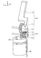
- FIG. 2 is a diagram for explaining the outline of the driving mechanism of the forceps 10. In FIG. 2, only the configuration necessary for explaining the outline of the drive mechanism among the configurations of the forceps 10 is illustrated.
- the forceps 10 opens and closes the end effector 110 when the driving force generated by the drive unit 101 is transmitted to the end effector 110 by the two cables 105.
- the two cables 105 are extended into a tubular casing constituting the tubular portion 103.
- the force sensor 107 for force feedback described above is provided at the base end of the end effector 110, that is, at the front stage of the end effector 110.
- the force sensor 107 is a six-axis force sensor, and is configured to measure a force in the x-axis direction, a force in the y-axis direction, a force in the z-axis direction, a moment around the x-axis, a moment around the y-axis, and a moment around the z-axis. Can be detected.
- the force sensor 107 may be attached to the end effector 110 itself. However, if the force sensor 107 is attached to the end effector 110, the configuration of the end effector 110 is increased, which may increase the burden on the patient. In addition, since the end effector 110 is a part that directly contacts the patient's body tissue, for example, a special configuration for maintaining cleanliness is required so that the force sensor 107 can withstand autoclaving. It becomes complicated.
- the force sensor 107 is provided between the end effector 110 that is a movable portion and the drive unit 101 that drives the end effector 110. Therefore, the enlargement and complication of the end effector 110 as described above can be avoided.
- the drive unit 101 applies rotation about the axis to the cable 105 (that is, applies a force that twists in the z-axis direction). Then, the driving force is transmitted to the end effector 110 by the rotation of the cable 105, and the end effector 110 is operated.
- the driving force transmitted by the cable 105 can affect the detection value of the force sensor 107.
- the driving force affects the moment around the z-axis corresponding to the rotation around the axis of the cable 105 among the detection values of the force sensor, but almost does not affect other detection values such as the force in the translational direction. Has no effect.
- the force in the x-axis direction, the force in the y-axis direction, the force in the z-axis direction, the moment around the x-axis, and the y-axis of the end effector 110 The detection priority is high for the moments around, but the detection priority is low for the moments around the z-axis.
- a moment around the z-axis may be generated in the end effector 110 when the end effector 110 contacts the patient's biological tissue. This is because the nature is considered low.
- a driving force for driving the end effector 110 is transmitted from the driving unit 101 to the end effector 110 using a force or moment in a direction in which the detection priority of the force sensor 107 is low. Therefore, even if the driving force has an influence on the detection value of the force sensor 107, a force or moment that can be noticeably affected by the driving force has a low detection priority, and therefore does not cause much problem. Therefore, according to this embodiment, it is possible to detect a force and a moment in a direction with a high detection priority with high accuracy.
- the “priority of detection” can be appropriately determined according to the type and characteristics of the medical instrument to be used (forceps 10 in this embodiment), the use of the detected force (force feedback, etc.), and the like.
- the present embodiment as described above, it is possible to accurately detect the force and moment in the direction in which the detection priority is high.
- highly accurate force feedback can be performed by performing force feedback to the operator using the force and moment detected with high accuracy.
- the working time directly affects the invasiveness, so that the burden on the patient's body can be reduced by performing the operation more quickly and accurately.
- FIG. 3 is a perspective view of a configuration in the vicinity of the end effector 110 of the forceps 10. 3 and FIG. 6 to be described later, only the outlines of the casings (the tubular casing 109 and the end effector casing 111 to be described later) are illustrated by broken lines in order to describe the internal configuration.
- FIG. 4 is an exploded perspective view of the configuration in the vicinity of the end effector 110 for explaining the driving force transmission mechanism.
- the end effector 110 has a pair of blades 119, but a similar driving force transmission mechanism is provided for each blade 119.
- FIG. 4 in the configuration in the vicinity of the end effector 110, the tubular casing 109 and the end effector casing 111 are not shown, and only the transmission mechanism related to one blade 119 is illustrated.
- FIG. 5 is an enlarged view showing a configuration in the vicinity of a rotating shaft 117 and a gear mechanism 116 of a blade 119 described later in FIG.
- FIG. 6 is a diagram illustrating a state where an object is gripped by the blade 119 in the end effector 110.
- an end effector casing 111 constituting the end effector 110 is attached to the distal end of the tubular casing 109 of the tubular portion 103 of the forceps 10.
- the end effector casing 111 has a cylindrical shape having substantially the same diameter as the tubular casing 109, and only the side wall located in the y-axis direction extends in the z-axis direction more than the side wall located in the other direction. Is formed.
- a second gear 113 (to be described later) and a rotating shaft portion 117 of the blade 119 are pivotally supported on the side wall located in the y-axis direction.
- the force sensor 107 is attached to the end effector casing 111 and detects a force corresponding to the distortion of the end effector casing 111.
- the gear mechanism 116 includes a first gear 112, a second gear 113, a third gear 114, and a fourth gear 115.
- the tip of the cable 105 extending in the z-axis direction in the tubular casing 109 is connected to the first gear 112.
- the first gear 112 is a worm
- the cable 105 is connected to one end thereof, and the other end is pivotally supported by the support member 120.
- the support member 120 is configured by forming a plate-like member having a substantially rectangular plate surface into a crank shape.
- a partial area of the opening connected to the tubular casing 109 is provided with a flat surface that contacts the cylindrical bottom surface, and the side that corresponds to one end of the crank shape of the support member 120 corresponds to the end end. It is fixed to a plane that hits the bottom surface of the effector casing 111.
- the side of the support member 120 that corresponds to the other end of the crank shape extends so as to cover the end of the first gear 112 on the side to which the cable 105 is not connected, and pivotally supports the first gear 112.
- the first gear 112 is disposed so that the cable 105 and the rotation axis thereof are coaxial (that is, the rotation axis is in the z-axis direction). Therefore, when a driving force is applied to the cable 105 so as to be rotated (twisted) by the driving unit 101 in the z-axis direction, the first gear 112 rotates around the z-axis.
- the second gear 113 which is a bevel gear, meshes with the first gear 112.
- the second gear 113 is pivotally supported on the side wall located in the y-axis direction of the end effector casing 111 as described above, and is arranged so that the rotation axis thereof is parallel to the y-axis direction.
- the second gear 113 converts the rotation of the first gear 112 around the z axis into rotation around the y axis. That is, the second gear 113 corresponds to the worm wheel, and the first gear 112 and the second gear 113 constitute a worm gear.
- a third gear 114 having a coaxial rotation shaft is fixedly connected to the second gear 113. That is, the third gear 114 rotates around the y-axis as the second gear 113 rotates.
- the fourth gear 115 meshes with the third gear 114.
- the fourth gear 115 is also disposed so that its rotation axis is parallel to the y-axis direction, and rotates around the y-axis as the third gear 114 rotates.
- the blade 119 is a plate-like member having a substantially rectangular plate surface, and has a substantially cylindrical rotary shaft portion 117 provided at one end in the long side direction, and a flat plate portion 118 which is another flat plate portion. It consists of.
- the rotating shaft 117 is pivotally supported on the side wall of the end effector casing 111 that is located in the y-axis direction as described above.
- a fourth gear 115 is fixedly connected to the surface of the rotating shaft 117 opposite to the surface facing the side wall of the end effector casing 111 so that the rotating shaft 117 and the rotating shaft are coaxial. That is, the rotation shaft portion 117 rotates around the y axis as the fourth gear 115 rotates.
- the pair of blades 119 are arranged so that the flat plate portions 118 can face each other when the blades 119 are rotated in the opposite directions around the rotation shaft portion 117. That is, when each of the pair of blades 119 rotates in the opposite direction around the rotation shaft portion 117, the plate portions 118 that face each other operate to open and close, and a living tissue or the like is gripped between the facing surfaces. be able to.
- FIG. 6 illustrates a state where the object 201 is gripped by the blade 119.
- a reaction force f acts on the blade 119 from the object 201.
- the reaction force f applied to the blade 119 acts on the end effector housing 111 via the blade 119 and the gear mechanism 116, and causes the end effector housing 111 to be distorted.
- the reaction force f that is, the force acting on the blade 119 can be detected.
- the rotation around the axis of the cable 105 is transmitted to the blade 119 by the gear mechanism 116, whereby the opening / closing operation of the blade 119 is realized. Therefore, as described with reference to FIG. 2, it is possible to accurately detect forces and moments other than the moments around the z-axis that have higher priority to be detected by the forceps 10.
- the cable 105 is not particularly limited as long as it can transmit the rotational force, and the cable 105 is a material having sufficient torsional rigidity to efficiently transmit the driving force. Preferably, it is formed by. Further, in order to reduce elastic twisting in the cable 105, the gear mechanism 116 is preferably configured to have a high reduction ratio.
- the blade 119 is operated by the pair of cables 105, thereby realizing the opening / closing operation of the pair of blades 119.
- the rotations about the axis given to the cable 105 for the opening / closing operation of the blade 119 are preferably opposite to each other.
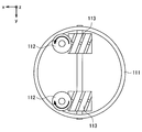
- FIG. 7 is a diagram for explaining the rotation direction of the cable 105 (the rotation direction of the first gear 112).
- FIG. 7 illustrates a state in which the forceps 10 is viewed from the distal end side (from the positive direction of the z axis).
- FIG. 7 only the side wall of the end effector casing 111, the first gear 112, and the second gear 113 are shown for simplicity. Further, the direction of rotation of the first gear 112 is schematically shown by an arrow.
- the first gear 112 when the two cables 105 are rotated in directions opposite to each other, the first gear 112 also rotates in directions opposite to each other.
- the gears and blades 119 arranged at the subsequent stage of the first gear 112 also operate in opposite directions.
- the magnitude of the force in the rotational direction applied to the two cables 105 is the same, the force exerted on the end effector housing 111 by the force is canceled, and the detection value of the force sensor 107 is obtained. It will not have an effect on it. That is, the influence of the rotational force on the two cables 105 on the force sensor 107 is offset. Therefore, according to this configuration, it is possible to detect the moment in the z-axis direction with high accuracy.
- a force sensor 107 detects a moment around the z-axis that is generated when the blade 119 is operated, and the force sensor 107 detects the total of the detected values for each blade 119. An operation of correcting the output value 107 can be performed.
- Which idea is used to design a medical device can be determined according to the type, characteristics, application, and the like of the medical device. For example, as in the forceps 10 described above, when the priority of detection of a force or moment related to a specific degree of freedom is low due to its usage, the first idea can be suitably employed.
- the driving force is transmitted from the driving unit 101 to the end effector 110 by the rotation around the axis of the cable 105 corresponding to the moment around the z axis.
- the configuration of the specific transmission mechanism can be appropriately changed accordingly.
- the driving force is transmitted to the catheter using a force or moment in a direction with a lower detection priority than the other. For example, if the priority of detection of the force in the z-axis direction is low depending on the use of the medical device, the driving force is transmitted to the movable part at the tip by the tension in the cable constituting the transmission mechanism. Good.
- the second idea can be suitably employed.
- the two transmission mechanisms that transmit the driving force transmit the driving force using the force or moment according to the same degree of freedom, and What is necessary is just to comprise so that the direction of the said force or moment may become reverse direction mutually.
- the number of driving force transmission mechanisms that is, the number of cables 105 for transmitting the driving force is two, but the present disclosure is not limited to such an example.
- the number of transmission mechanisms (number of cables 105) can also be appropriately determined according to the concept to be adopted.
- the number of transmission mechanisms is not particularly limited, and the configuration based on the first idea can be realized by an arbitrary number of transmission mechanisms.
- the number of transmission mechanisms that can realize the configuration based on the second idea can be limited in principle. For example, when the number of transmission mechanisms is one, there is no counter party to cancel out, and thus a configuration based on the second idea cannot be realized. Further, even when the number of transmission mechanisms is an odd number, it is considered that it is practically difficult to configure these transmission mechanisms so that the influence of the driving force cancels out. Therefore, the configuration based on the second idea can be preferably configured such that the number of transmission mechanisms is an even number.
- these transmission mechanisms are configured to transmit the driving force by using the force or moment with the same degree of freedom, and the direction of half of these forces or moments is the other half of the force or moment.
- the medical instrument that is the subject of the present disclosure is a medical instrument that has at least one movable part on the distal end side, and that realizes the operation of the movable part by transmitting a driving force from the proximal end by a cable or the like.
- the type is not limited.
- the medical instrument is supported by the support arm device 400 .
- the medical instrument according to the present disclosure is a medical instrument that is directly held and operated by an operator. It may be an instrument.
- an operation unit such as a gripper for the operator to operate the medical instrument is provided on the proximal end side of the medical instrument.
- the movement of the medical instrument can be controlled.
- feedback of contact force can be realized by providing the operation unit with a mechanism for presenting the force detected by the force sensor to the operator.
- FIG. 8 is a diagram illustrating a configuration example of a forceps having a bent portion.
- FIG. 8 as in FIG. 2, only the configuration necessary for explaining the outline of the drive mechanism is illustrated in the configuration of the forceps according to this modification.
- the drive unit 101 and the end effector 110 are connected by a cable 105a.
- a driving force is transmitted from the driving unit 101 to the end effector 110 via the cable 105a.
- the configurations of the drive unit 101, the force sensor 107, and the end effector 110 are the same as those in the above-described embodiment. Accordingly, a force is applied to the cable 105a by the driving unit 101 in a direction in which the cable 105a is rotated about its axis, and the rotation is transmitted to the blade 119 by the gear mechanism 116 shown in FIGS. The blade 119 opens and closes. Further, a force acting on the end effector 110 is detected by a force sensor 107 provided at the base end of the end effector 110.
- a bent portion 130 exists between the drive unit 101 and the end effector 110.
- the forceps 10 a has one bent portion 130, but a plurality of bent portions 130 may be provided between the drive unit 101 and the end effector 110.
- a flexible cable capable of transmitting rotation around the axis even when bent is used as the cable 105a.
- the rotation of the cable 105a around the axis is transmitted to the end effector 110, and the end effector 110 is opened and closed. Can do.
- the same effect as that of the above-described embodiment can be obtained by transmitting the driving force as the rotation around the axis of the cable 105a. That is, since the driving force is transmitted by a moment around the z-axis having a lower detection priority in the force sensor 107, it becomes possible to accurately detect a force and a moment in another direction having a higher priority. .
- the said structure since the connection angle between links can be freely changed in the joint part, the said structure can also be used instead of the flexible cable 105a in the modification mentioned above. That is, instead of the cable 105a, a forceps 10a having a bent portion 130 may be realized by using a configuration in which a plurality of links are continuously connected by a universal joint.
- the case where the target to which the configuration according to the present disclosure (that is, the configuration based on the first and / or the second concept) can be applied is a medical device. It is not limited to.
- the configuration according to the present disclosure is an instrument that has at least one movable portion on the distal end side, and that realizes the operation of the movable portion by transmitting a driving force from the proximal end by a cable or the like. Any instrument provided with a force sensor for detecting the acting force is not limited to medical use, and can be applied to any instrument. By applying the configuration according to the present disclosure to such an instrument, the force acting on the movable part can be detected with high accuracy.
- a plurality of the movable parts are provided, and a drive force transmission mechanism from each of the drive parts to each of the movable parts is provided for each of the movable parts, and the movable parts are moved from the drive parts via the plurality of transmission mechanisms.
- the medical instrument according to (1) wherein when the driving force is transmitted to each of the units, the influence of the driving force on the detection value of the force sensor is offset.
- (3) Transmission of driving force from the driving unit to the movable unit is transmitted by the rotation of the axis around a cable extending between the driving unit and the movable unit by the driving unit.
- the medical device according to (1) or (2).
- the movable portion is an end effector that grips a patient's biological tissue or medical device between the opposing surfaces by operating each of two plate-like members arranged to face each other.
- the medical instrument is a forceps having a tubular housing, the driving unit is provided at a proximal end of the tubular housing, and the movable unit provided at a distal end of the tubular housing is: An end effector for grasping a patient's biological tissue or medical device, and rotating around an axis by the drive unit to a cable extending between the drive unit and the movable unit inside the tubular casing.
- the medical instrument according to any one of (1) to (6), wherein a driving force is transmitted from the driving unit to the movable unit.
- a bending portion is provided between the drive portion and the end effector, and the cable is formed of a flexible material that can rotate around an axis even when bent.
- Medical device (9) The medical device according to (7) or (8), wherein the drive unit and the tubular casing are configured to be detachable. (10) an arm part to which a medical instrument is attached at the tip, wherein the medical instrument has at least one movable part for performing a predetermined process on a biological tissue of a patient, and is based on the movable part.
- a drive unit that is provided on an end side and that operates the movable unit; and a force sensor that is provided between the drive unit and the movable unit and detects a contact force in the movable unit
- the medical support arm device in which the driving force is transmitted from the driving unit to the movable unit using a force or a moment in a direction in which the detection priority of the force sensor is low in the instrument.
- (11) The medical support arm device according to (10), wherein a force acting on the movable part is fed back to an operator who operates the movable part based on a detection value of the force sensor.
Landscapes
- Health & Medical Sciences (AREA)
- Surgery (AREA)
- Engineering & Computer Science (AREA)
- Life Sciences & Earth Sciences (AREA)
- Medical Informatics (AREA)
- Robotics (AREA)
- Biomedical Technology (AREA)
- Heart & Thoracic Surgery (AREA)
- Nuclear Medicine, Radiotherapy & Molecular Imaging (AREA)
- Molecular Biology (AREA)
- Animal Behavior & Ethology (AREA)
- General Health & Medical Sciences (AREA)
- Public Health (AREA)
- Veterinary Medicine (AREA)
- Manipulator (AREA)
- Surgical Instruments (AREA)
Abstract
医療用機器(10)は駆動部(101)、及び駆動部(101)からz軸方向に延伸する管状部(103)を有する。管状部(103)の先端にはエンドエフェクタ(110)が設けられている。駆動部(101)が発生する駆動力は、管状部(103)の中を通る2本のケーブル(105)を介してエンドエフェクタ(110)に伝達され、エンドエフェクタ(110)をx-z平面内で開閉する。エンドエフェクタ(110)の基端には、エンドエフェクタ(110)に作用する力を検出する力センサ(107)が設けられている。ケーブル(105)はz軸に平行な軸まわりに回転することで駆動力を伝達する。よって、駆動力は、力センサ(107)が検出するz軸まわりのモーメントの値に影響を及ぼし得る。しかしながら、検出する優先度の高い、x軸方向の力、y軸方向の力、z軸方向の力、x軸まわりのモーメント及びy軸まわりのモーメントは、力センサ(107)で高精度に検出できる。
Description
本開示は、医療用器具及び医療用支持アーム装置に関する。
近年、支持アーム装置のアーム部によって鉗子等の医療用器具を支持し、当該アーム部及び当該医療用器具を術者が操作しながら手術を行う手術システムが開発されている。このような手術システムでは、術者の操作性を向上させるため、また、手術の安全性向上のために、医療用器具の先端が患者の体組織等に接触する際に生じる力及びモーメント(以下、接触力ともいう)を術者に高精度にフィードバック可能な技術が求められている。
そこで、医療用器具の先端に作用する力を検出するための技術が多数開発されている。例えば、特許文献1には、術者によって遠位端(先端)のエンドエフェクタが遠隔操作される医療用器具であって、当該エンドエフェクタに作用する力を検出するための力センサを備える医療用器具が開示されている。
ここで、特許文献1に記載の医療用器具では、当該医療用器具の内部に延設されるケーブルに張力を与えることによって、エンドエフェクタや、当該エンドエフェクタの前段(基端側)に設けられる関節部(屈曲部)が駆動される。力センサは、エンドエフェクタ及び屈曲部の前段に設けられ得るが、この構造では、エンドエフェクタ及び屈曲部を駆動する際にケーブルに作用する張力によって力センサの周囲の部材に応力が発生し、当該応力が力センサによって検出されてしまう恐れがある。
このように、近接端(基端)からケーブル等によって先端のエンドエフェクタ等に駆動力を伝達する構成を有する医療用器具では、エンドエフェクタ等を動作させるために当該ケーブルに生じる力が、力センサに干渉してしまう可能性がある。従って、力センサの定格のマージンを十分に取る必要があり、その結果、力センサの感度(すなわち検出精度)が低下する。力センサの感度が低下すると、術者への力のフィードバックを高精度に行うことができなくなる恐れがある。特に、例えばマイクロサージャリーのような微細な作業が要求される場合には、先端での接触力の検出の感度及び分解能はより高いことが求められるため、このような力センサの感度の低下は好ましくない。
そこで、本開示では、より精度良く接触力を検出することが可能な、新規かつ改良された医療用器具及び医療用支持アーム装置を提案する。
本開示によれば、患者の生体組織に対して所定の処理をするための少なくとも1つの可動部と、前記可動部よりも基端側に設けられ、前記可動部を動作させる駆動部と、前記駆動部と前記可動部との間に設けられ、前記可動部における接触力を検出する力センサと、を備え、前記力センサにおける検出の優先度が低い方向の力又はモーメントを用いて、前記駆動部から前記可動部への駆動力の伝達が行われる、医療用器具が提供される。
また、本開示によれば、先端に医療用器具が取り付けられるアーム部、を備え、前記医療用器具は、患者の生体組織に対して所定の処理をするための少なくとも1つの可動部と、前記可動部よりも基端側に設けられ、前記可動部を動作させる駆動部と、前記駆動部と前記可動部との間に設けられ、前記可動部における接触力を検出する力センサと、を有し、前記医療用器具においては、前記力センサにおける検出の優先度が低い方向の力又はモーメントを用いて、前記駆動部から前記可動部への駆動力の伝達が行われる、医療用支持アーム装置が提供される。
本開示によれば、医療用器具において、力センサにおける検出の優先度が低い方向の力又はモーメントを用いて、駆動部から可動部への駆動力の伝達が行われる。従って、当該駆動力が力センサの検出値に影響を及ぼしたとしても、より優先度の高い他の方向の力及びモーメントは高精度に検出することができる。従って、医療用器具における接触力をより精度良く検出することが可能になる。
以上説明したように本開示によれば、より精度良く接触力を検出することが可能になる。なお、上記の効果は必ずしも限定的なものではなく、上記の効果とともに、又は上記の効果に代えて、本明細書に示されたいずれかの効果、又は本明細書から把握され得る他の効果が奏されてもよい。
以下に添付図面を参照しながら、本開示の好適な実施の形態について詳細に説明する。なお、本明細書及び図面において、実質的に同一の機能構成を有する構成要素については、同一の符号を付することにより重複説明を省略する。
なお、説明は以下の順序で行うものとする。
1.支持アーム装置の構成
2.鉗子の構成
2-1.鉗子の駆動機構の概要
2-2.鉗子の駆動機構の詳細
3.本実施形態についてのまとめ
4.変形例
4-1.鉗子が屈曲部を有する場合
4-2.ケーブルについての変形例
5.補足
1.支持アーム装置の構成
2.鉗子の構成
2-1.鉗子の駆動機構の概要
2-2.鉗子の駆動機構の詳細
3.本実施形態についてのまとめ
4.変形例
4-1.鉗子が屈曲部を有する場合
4-2.ケーブルについての変形例
5.補足
なお、以下では、本開示の一実施形態として、医療用器具が鉗子であり、当該医療用器具が支持アーム装置のアーム部によって支持される場合について説明する。また、本実施形態では、当該支持アーム装置は、いわゆるマスター/スレイブ方式の手術システムにおけるスレイブを構成し得る。つまり、支持アーム装置のアーム部及び鉗子は術者によって遠隔操作可能に構成されている。
(1.支持アーム装置の構成)
図1を参照して、本開示の一実施形態に係る支持アーム装置の構成を説明する。図1は、本実施形態に係る支持アーム装置の一構成例を示す図である。
図1を参照して、本開示の一実施形態に係る支持アーム装置の構成を説明する。図1は、本実施形態に係る支持アーム装置の一構成例を示す図である。
図1を参照すると、支持アーム装置400は、ベース部410と、アーム部420と、制御装置440と、を備える。支持アーム装置400は、手術時に鉗子等の医療用器具を支持する医療用支持アーム装置である。
ベース部410は支持アーム装置400の基台であり、ベース部410からアーム部420が延伸される。ベース部410にはキャスターが設けられており、支持アーム装置400は、当該キャスターを介して床面と接地し、当該キャスターによって床面上を移動可能に構成されている。ただし、本実施形態に係る支持アーム装置400の構成はかかる例に限定されず、例えば、ベース部410が設けられず、手術室の天井又は壁面にアーム部420が直接取り付けられて支持アーム装置400が構成されてもよい。例えば、天井にアーム部420が取り付けられる場合には、支持アーム装置400は、アーム部420が天井から吊り下げられて構成されることとなる。
ベース部410の内部には、支持アーム装置400の制御に係る各種の情報処理を実行する制御装置440が設けられる。制御装置440は、例えばCPU(Central Processing Unit)やDSP(Digital Signal Processor)等のプロセッサであり得る。あるいは、制御装置440は、これらのプロセッサ及びメモリ等の記憶素子が搭載された制御基板やマイコンであり得る。制御装置440を構成するプロセッサが所定のプログラムに従って各種の信号処理を実行することにより、支持アーム装置400における各種の動作が実行される。具体的には、制御装置440からの制御により、アーム部420及び後述する鉗子10が駆動される。
アーム部420は、複数の関節部421a、421b、421c、421d、421e、421fと、関節部421a~421eによって互いに回動可能に連結される複数のリンク422a、422b、422c、422dと、アーム部420の先端に関節部421fを介して回動可能に設けられる鉗子10と、を有する。
リンク422a~422dは棒状の部材であり、リンク422aの一端が関節部421aを介してベース部410と連結され、リンク422aの他端が関節部421bを介してリンク422bの一端と連結され、更に、リンク422bの他端が関節部421c、421dを介してリンク422cの一端と連結される。更に、リンク422cの他端が、関節部421eを介して略L字状のリンク422dの一端と連結され、リンク422dの他端と鉗子10とが、関節部421fを介して連結される。このように、ベース部410を支点として、複数のリンク422a~422dの端同士が、関節部421a~421fによって互いに連結されることにより、ベース部410から延伸されるアーム形状が構成される。
関節部421a~421fには、アクチュエータが設けられており、関節部421a~421fは、当該アクチュエータにより所定の回転軸に対して回転可能に構成されている。当該アクチュエータは、モータ、エンコーダ及びトルクセンサ等によって構成され得る。各関節部421a~421fのアクチュエータのモータの駆動が、制御装置440によってそれぞれ制御されることにより、例えばアーム部420を伸ばしたり、縮めたり(折り畳んだり)といった、アーム部420の駆動が制御される。なお、本実施形態では、アーム部420の制御方式としては各種の公知の制御方式が用いられてよいため、ここではその詳細な説明は省略する。
アーム部420を動作させる際には、術者は、支持アーム装置400から離れた位置に設けられる入力装置(図示せず)を介して、支持アーム装置400に対してアーム部420の動作に関する指示を与える。具体的には、入力装置を介して入力された指示を示す信号は、制御装置440に送信される。制御装置440は、各関節部421a~421fのアクチュエータのエンコーダ及びトルクセンサによって検出された各関節部421a~421fの状態に基づいて、当該指示に応じた各関節部421a~421fのアクチュエータのモータの制御量を算出する。算出された当該制御量に応じて各アクチュエータのモータが駆動されることにより、術者の指示に従ってアーム部420が動作することとなる。なお、入力装置と制御装置440との間の通信は、有線又は無線の各種の公知の方法によって行われてよい。
なお、図示する例では、支持アーム装置400は、6つの関節部421a~421fを有し、アーム部420の駆動に関して6自由度が実現されている。アーム部420が6自由度を有するように構成されることにより、アーム部420の可動範囲内において鉗子10を自由に移動させることができる。これにより、鉗子10を、様々な角度から患者に対して挿入することが可能になり、鉗子10を操作する際の自由度が向上する。
ただし、アーム部420の構成は図示する例に限定されず、関節部421a~421f及びリンク422a~422dの数や配置、関節部421a~421fの駆動軸の方向等は、アーム部420が所望の自由度を有するように適宜設定されてよい。ただし、鉗子10の位置及び姿勢の自由度を考慮して、アーム部420は、好適に、6自由度以上の自由度を有するように構成され得る。
鉗子10は、基端に設けられる駆動部101と、駆動部101から延伸する長尺な管状部103と、からなる。管状部103の先端にはエンドエフェクタが設けられており、手術時には、当該先端を含む所定の長さの領域が、患者の体腔内に挿入される。エンドエフェクタは開閉可能な一対のブレードからなり、当該ブレードによって、患者の生体組織の把持や切断、又は生体組織の縫合時における針等の医療デバイスの把持等を行うことができる。手術を行う際には、鉗子10が患者の生体組織に対して所望の位置及び姿勢を取り得るように、制御装置440によってアーム部420及び鉗子10の位置及び姿勢が制御される。
駆動部101は、例えばモータや当該モータを駆動するためのドライバIC(Integrated Circuit)等からなり、管状部103を駆動させる。例えば、駆動部101によって管状部103のエンドエフェクタの開閉動作が行われる。また、管状部103が関節部(屈曲部)を有する場合であれば、駆動部101によって当該屈曲部における屈曲動作が行われてもよい。
なお、駆動部101は非清潔領域に属し、管状部103は清潔領域に属する。管状部103のみを容易に洗浄、滅菌できるように、鉗子10は、駆動部101と管状部103とが脱着可能に構成され得る。
鉗子10は、術者によって遠隔操作可能な、いわゆるロボット鉗子である。鉗子10を動作させる際には、術者は、例えば上述したアーム部420を遠隔操作するための入力装置を介して、支持アーム装置400の制御装置440に対して鉗子10の動作に関する指示を入力する。当該指示に基づいて、管状部103を動作させるための駆動部101のモータの制御量が制御装置440によって算出され、算出された当該制御量に応じて当該モータが駆動されることにより、術者の指示に従って鉗子10が動作することとなる。
なお、図1では、簡単のため、管状部103の具体的な形状の図示を省略し、簡易的に棒状の部材として図示している。管状部103の構成や、駆動部101によって管状部103を駆動するための具体的な機構については、下記(2.鉗子の構成)で詳しく説明する。
管状部103のエンドエフェクタの基端部分には、当該エンドエフェクタに作用する力を検出するための力センサ(図示せず)が設けられる。支持アーム装置400には、当該力センサの検出値に基づいて、エンドエフェクタに作用した力を術者に対してフィードバックする機能が備えられている。
例えば、アーム部420及び鉗子10を操作するための入力装置に、エンドエフェクタに作用する力を術者に対して提示する機能が設けられ得る。例えば、当該入力装置には、エンドエフェクタに作用する力に応じて、術者による操作に対して抵抗を与えるように当該入力装置を構成するレバー等を駆動させる機構が設けられ得る。
エンドエフェクタに作用する力は、すなわち、エンドエフェクタが患者の生体組織と接触することにより当該生体組織から受ける反力であり得るため、エンドエフェクタに作用する力が術者に対してフィードバックされることにより、術者は、直接自身の手で鉗子を持って手術を行っているかのような感覚を得ることができ、操作性が向上する。また、過度な力が生体組織に対して与えられることを防止することができるため、より安全な手術が実現され得る。
なお、力センサによって検出された力を術者に対してフィードバックするための具体的な構成としては、各種の公知の構成が適用されてよい。また、力を術者に対してフィードバックするための方法は上記の例に限定されず、各種の方法が用いられてよい。例えば、入力装置において術者が把持しているレバー等が振動することにより、力が術者に対してフィードバックされてもよい。また、例えば、術者が操作の際に視認する表示装置を介して、例えば所定の値以上の力が検出された場合等に、視覚的にそのことが術者に対して警告されてもよい。あるいは、入力装置にスピーカ等の音声出力装置が搭載されている場合であれば、当該警告は聴覚的に行われてもよい。
また、アーム部420の制御方式が力制御である場合には、力センサによって検出されたエンドエフェクタに作用する力が、当該アーム部420の制御に用いられてもよい。例えば、アーム部420を移動させている間に所定の値以上の力が検出された場合には、アーム部420がそれ以上その方向に移動しないように、当該アーム部420の駆動が制御されてもよい。これにより、生体組織に対して過度な力が与えられることをより確実に防止することが可能になる。
以上、図1を参照して、本実施形態に係る支持アーム装置400の構成について説明した。
(2.鉗子の構成)
図2-図7を参照して、鉗子10の構成について詳細に説明する。なお、以下の説明では、鉗子10において管状部103が延伸する方向をz軸方向とも呼称する。また、z軸方向と直交する平面内において互いに垂直な2方向を、それぞれ、x軸及びy軸とも呼称する。更に、x軸方向を鉗子10におけるエンドエフェクタの開閉方向として定義する。すなわち、エンドエフェクタは、x-z平面内で開閉動作を行う。
図2-図7を参照して、鉗子10の構成について詳細に説明する。なお、以下の説明では、鉗子10において管状部103が延伸する方向をz軸方向とも呼称する。また、z軸方向と直交する平面内において互いに垂直な2方向を、それぞれ、x軸及びy軸とも呼称する。更に、x軸方向を鉗子10におけるエンドエフェクタの開閉方向として定義する。すなわち、エンドエフェクタは、x-z平面内で開閉動作を行う。
(2-1.鉗子の駆動機構の概要)
まず、図2を参照して、鉗子10の駆動機構の概要について説明する。図2は、鉗子10の駆動機構の概要について説明するための図である。なお、図2では、鉗子10の構成のうち、駆動機構の概要について説明するために必要な構成のみを図示している。
まず、図2を参照して、鉗子10の駆動機構の概要について説明する。図2は、鉗子10の駆動機構の概要について説明するための図である。なお、図2では、鉗子10の構成のうち、駆動機構の概要について説明するために必要な構成のみを図示している。
図2に示すように、鉗子10は、駆動部101によって発生した駆動力が、2本のケーブル105によってエンドエフェクタ110に伝達されることにより、当該エンドエフェクタ110の開閉動作が行われる。図2では図示を省略しているが、実際には、2本のケーブル105は、管状部103を構成する管状の筐体内に延設される。
また、エンドエフェクタ110の基端、すなわちエンドエフェクタ110の前段には、上述した力フィードバック用の力センサ107が設けられる。力センサ107は、6軸の力センサであり、x軸方向の力、y軸方向の力及びz軸方向の力、並びにx軸まわりのモーメント、y軸まわりのモーメント及びz軸まわりのモーメントを検出することができる。
ここで、エンドエフェクタ110に作用する力を検出するためには、力センサ107は、エンドエフェクタ110自体に取り付けられてもよい。しかしながら、エンドエフェクタ110に力センサ107を取り付けると、エンドエフェクタ110の構成が大型化するため、患者に与える負担が大きくなる可能性がある。また、エンドエフェクタ110は患者の体組織に直接接触する部位であるため、例えば力センサ107がオートクレーブ処理に耐え得るような、清潔を保つための特別な構成が必要となり、エンドエフェクタ110の構成が複雑化してしまう。
そこで、本実施形態では、上記のように、力センサ107は、可動部であるエンドエフェクタ110と、当該エンドエフェクタ110を駆動する駆動部101との間に設けられる。これにより、上記のようなエンドエフェクタ110の大型化、複雑化を回避することができる。
一方、このような構成では、駆動部101からエンドエフェクタ110にケーブル105を介して駆動力が伝達される際に、当該駆動力が力センサの検出値に影響を及ぼしてしまう可能性がある。従って、エンドエフェクタ110に作用する力を高精度に検出することが困難となる恐れがある。上述した特許文献1に記載の医療用器具も、このような、基端に設けられる駆動部による駆動力が先端のエンドエフェクタにケーブルによって伝達される構成であるため、同様の問題が生じ得る。
そこで、本実施形態では、駆動部101によってケーブル105に対して軸まわりの回転を与える(すなわち、z軸方向に捻じるような力を与える)。そして、そのケーブル105の回転によって駆動力をエンドエフェクタ110に伝達し、当該エンドエフェクタ110を動作させる。
このような態様であっても、ケーブル105によって伝達される駆動力は、力センサ107の検出値に影響を及ぼし得る。しかしながら、当該駆動力は、力センサの検出値のうち、ケーブル105の軸まわりの回転に対応するz軸まわりのモーメントには影響を及ぼすものの、並進方向の力等、他の検出値にはほぼ影響を及ぼさない。
ここで、一般的に、鉗子10においては、力フィードバックの観点からは、そのエンドエフェクタ110のx軸方向の力、y軸方向の力、z軸方向の力、x軸まわりのモーメント及びy軸まわりのモーメントについては検出する優先度は高いが、z軸まわりのモーメントについては検出する優先度は低い。物体(患者の生体組織や医療デバイス等)を把持するというエンドエフェクタ110の用途から考えて、エンドエフェクタ110が患者の生体組織と接触した際に、z軸まわりのモーメントがエンドエフェクタ110に生じる可能性は低いと考えられるからである。
つまり、本実施形態では、力センサ107における検出の優先度が低い方向の力又はモーメントを用いて、エンドエフェクタ110を駆動するための駆動力を、駆動部101からエンドエフェクタ110に伝達する。従って、もしも当該駆動力が力センサ107の検出値に対して影響を及ぼしたとしても、その影響が顕著に現れ得る力又はモーメントは検出の優先度が低いものであるため、さほど問題とならない。よって、本実施形態によれば、検出の優先度が高い方向の力及びモーメントについては高精度に検出することが可能となるのである。なお、「検出の優先度」は、用いる医療用器具(本実施形態であれば鉗子10)の種類、特性や、検出した力の用途(力フィードバック等)等に応じて、適宜決定され得る。
ここで、上記特許文献1に代表される既存の構成では、ケーブルに張力を与えることにより(すなわち、ケーブルにz軸方向の力を与えることにより)駆動力をエンドエフェクタに伝達し、当該エンドエフェクタを動作させる。従って、当該駆動力は、力センサによるz軸方向の力についての検出値に顕著に影響を及ぼすこととなる。このように、既存の構成では、検出の優先度が高いz軸方向の力についての検出精度が低下してしまうため、高精度な力フィードバックを行うことが困難であると考えられる。
一方、本実施形態によれば、上記のように、検出の優先度が高い方向の力及びモーメントについて精度良く検出することが可能となる。例えば、精度良く検出された力及びモーメントを用いて術者への力フィードバックを行うことにより、高精度な力フィードバックを行うことが可能になる。例えば、本実施形態に係る構成を用いることによって、脳神経外科手術のようなマイクロサージャリーにおいて軟組織を取り扱う際に微小な接触力を検出し、術者にフィードバックすることが可能になる。従って、手術の安全性と作業効率を向上させることができる。特に、血管吻合においては作業時間がそのまま侵襲性に影響を与えるため、より迅速にかつ正確に手術を行うことにより、患者の身体への負担を軽減させることができる。
(2-2.鉗子の駆動機構の詳細)
次に、図3-図6を参照して、鉗子10の構成についてより詳細に説明する。図3は、鉗子10のエンドエフェクタ110近傍の構成の斜視図である。なお、図3及び後述する図6では、内部の構成について説明するために、筐体(後述する管状の筐体109及びエンドエフェクタ筐体111)はその輪郭のみを破線で図示している。
次に、図3-図6を参照して、鉗子10の構成についてより詳細に説明する。図3は、鉗子10のエンドエフェクタ110近傍の構成の斜視図である。なお、図3及び後述する図6では、内部の構成について説明するために、筐体(後述する管状の筐体109及びエンドエフェクタ筐体111)はその輪郭のみを破線で図示している。
図4は、駆動力の伝達機構を説明するための、エンドエフェクタ110近傍の構成の分解斜視図である。なお、後述するように、エンドエフェクタ110は、1対のブレード119を有するが、各ブレード119に対してそれぞれ同様の駆動力の伝達機構が設けられる。図4では、エンドエフェクタ110近傍の構成のうち、管状の筐体109及びエンドエフェクタ筐体111の図示を省略するとともに、一方のブレード119に係る伝達機構のみを図示している。
また、図5は、図4における、後述するブレード119の回転軸部117及び歯車機構116近傍の構成を示す拡大図である。図6は、エンドエフェクタ110において、ブレード119によって物体が把持される様子を示す図である。
図3を参照すると、鉗子10の管状部103の管状の筐体109の先端に、エンドエフェクタ110を構成するエンドエフェクタ筐体111が取り付けられる。エンドエフェクタ筐体111は、管状の筐体109と略同径の円筒形状を有し、そのy軸方向に位置する側壁のみが、他の方向に位置する側壁よりもz軸方向に延伸するように形成されている。当該y軸方向に位置する側壁に、後述する第2のギア113と、ブレード119の回転軸部117と、が軸支される。また、力センサ107は、エンドエフェクタ筐体111に取り付けられており、エンドエフェクタ筐体111の歪みに応じた力を検出する。
エンドエフェクタ110では、ケーブル105によって伝達されてきた駆動力が、歯車機構116によってブレード119に伝達される。歯車機構116は、第1のギア112と、第2のギア113と、第3のギア114と、第4のギア115と、からなる。
具体的には、図3-図5に示すように、管状の筐体109内においてz軸方向に延設されるケーブル105の先端が、第1のギア112に接続される。第1のギア112はウォームであり、その一端にケーブル105が接続され、他端が支持部材120によって軸支される。
支持部材120は、略矩形形状の板面を有する板状部材がクランク状に形成されて構成される。エンドエフェクタ筐体111の、管状の筐体109と接続される開口部の一部領域には円筒形状の底面に当たる平面が設けられており、支持部材120のクランク形状の一端に当たる辺が、当該エンドエフェクタ筐体111の底面に当たる平面に固定される。そして、支持部材120のクランク形状の他端に当たる辺が、第1のギア112の、ケーブル105が接続されない側の端を覆うように延設され、当該第1のギア112を軸支する。
第1のギア112は、ケーブル105とその回転軸が同軸になるように(すなわち、その回転軸がz軸方向となるように)配設される。従って、駆動部101によってz軸方向に回転させるように(捻じるように)ケーブル105に対して駆動力が与えられると、第1のギア112はz軸まわりに回転する。
第1のギア112には、斜歯歯車である第2のギア113が歯合する。第2のギア113は上記のようにエンドエフェクタ筐体111のy軸方向に位置する側壁に軸支され、その回転軸がy軸方向と平行になるように配設される。第2のギア113によって、第1のギア112のz軸まわりの回転がy軸まわりの回転に変換される。つまり、第2のギア113がウォームホイールに対応するものであり、第1のギア112及び第2のギア113によってウォームギアが構成される。
第2のギア113には、同軸の回転軸を有する第3のギア114が固定的に接続される。すなわち、第3のギア114は、第2のギア113の回転に伴ってy軸まわりに回転する。
第3のギア114には、第4のギア115が歯合する。第4のギア115も、その回転軸がy軸方向と平行になるように配設されており、第3のギア114の回転に伴ってy軸まわりに回転する。
ブレード119は、略長方形形状の板面を有する板状の部材であり、その長辺方向の一端に設けられる略円筒形状の回転軸部117と、その他の平板形状の部位である平板部118と、からなる。回転軸部117は上記のようにエンドエフェクタ筐体111のy軸方向に位置する側壁に軸支される。回転軸部117のエンドエフェクタ筐体111の側壁と対向する面の逆側の面には、回転軸部117と回転軸が同軸になるように第4のギア115が固定的に接続される。すなわち、回転軸部117は、第4のギア115の回転に伴ってy軸まわりに回転する。
1対のブレード119は、回転軸部117を中心にそれぞれが逆方向に回転したときに、その平板部118が互いに対向し得るように配設される。つまり、回転軸部117を中心に1対のブレード119のそれぞれが逆方向に回転することにより、互いに対向する平板部118が開閉するように動作し、当該対向面間で生体組織等を把持することができる。図6では、ブレード119によって物体201が把持される様子を図示している。
ここで、図6に示すように、ブレード119によって物体201が把持される場合には、物体201からブレード119に対して反力fが作用することとなる。ブレード119に対して加えられた反力fは、ブレード119及び歯車機構116を介してエンドエフェクタ筐体111に作用し、当該エンドエフェクタ筐体111に歪みを生じさせる。当該歪みに応じた力が力センサ107によって検出されることにより、反力f、すなわちブレード119に対して作用した力が検出され得る。なお、ここでは、一例として、把持している物体201によってブレード119に作用する力が検出される場合について説明したが、ブレード119が生体組織に単に衝突した(接触した)場合であっても、同様に、その衝突(接触)によってブレード119に作用した力が、力センサ107によって検出されることとなる。
以上説明したように、本実施形態に係る鉗子10では、ケーブル105の軸まわりの回転が、歯車機構116によってブレード119に伝達されることにより、ブレード119の開閉動作が実現される。従って、図2を参照して説明したように、鉗子10において検出する優先度がより高い、z軸まわりのモーメント以外の力及びモーメントを精度良く検出することが実現される。
なお、当該構成において、ケーブル105は回転力を伝達可能であればよく、その材質は特に限定されないが、ケーブル105は、駆動力を効率的に伝達するために、十分な捻じり剛性を有する材質によって形成されることが好ましい。また、ケーブル105における弾性捻じれを軽減するために、歯車機構116は高減速比であるように構成されることが望ましい。
ここで、上述したように、鉗子10では、1対のケーブル105によってそれぞれブレード119が動作されることにより、1対のブレード119の開閉動作が実現される。その際、ブレード119の開閉動作のためにケーブル105に与えられる軸まわりの回転は、互いに逆方向であることが好ましい。
図7は、ケーブル105の回転方向(第1のギア112の回転方向)について説明するための図である。図7では、鉗子10を先端側から(z軸の正方向から)見た様子を図示している。図7では、簡単のため、エンドエフェクタ筐体111の側壁、第1のギア112及び第2のギア113のみを図示している。また、第1のギア112の回転方向を模擬的に矢印で図示している。
図7に示すように、2本のケーブル105に対して互いに逆方向に回転が与えられた場合には、第1のギア112も互いに逆方向に回転する。第1のギア112の後段に配置される各ギアやブレード119も互いに逆方向に動作することになる。この場合には、2本のケーブル105に対して与えられる回転方向の力の大きさが同一であれば、当該力がエンドエフェクタ筐体111に及ぼす力が相殺され、力センサ107の検出値に対して影響を与えないこととなる。つまり、2本のケーブル105における回転方向の力が力センサ107に与える影響が相殺される。従って、当該構成によれば、z軸方向のモーメントも精度良く検出することが可能となる。
実際には、歯車機構116における各ギア間の摺動抵抗等の違いにより、2本のケーブル105に対して同一の大きさの力が逆方向に与えられた場合であっても、当該力が力センサ107の検出値に及ぼす影響を完全に相殺することは難しい。従って、鉗子10を組み立てた後に、キャリブレーション作業が行われてもよい。当該キャリブレーション作業では、例えば、ブレード119を動作させた際に発生するz軸まわりのモーメントを、ブレード119ごとに力センサ107によって検出し、その検出値の合計がゼロになるように、力センサ107の出力値を補正する作業が行われ得る。
当該構成によれば、駆動力の力センサ107への干渉を抑制することができるため、力センサ107として、その定格値が実際の接触力に近いものを用いることができる。従って、力センサ107における接触力の感度や分解能を向上させることができる。よって、力フィードバックをより高精度に行うことができる。また、鉗子10を支持するアーム部420の制御方式が力制御である場合には、当該力センサ107によって検出された接触力を用いてその制御を行うことにより、制御の精度を向上させることができる。
(3.本実施形態についてのまとめ)
以上説明したように、本実施形態では、力センサ107の検出精度を向上させるために、2つの思想が存在する。1つ目は、検出の優先度が低い方向の力又はモーメントを用いてエンドエフェクタ110を動作させるための駆動力を伝達することにより、当該駆動力が検出の優先度が高い方向の力及びモーメントの検出値に与える影響を低減する、というものである。2つ目は、エンドエフェクタ110を動作させるための駆動力の伝達機構が複数存在する場合に、それらの伝達機構における駆動力の伝達が力センサの検出値に与える影響が互いに相殺されるように、それらの伝達機構を構成する、というものである。
以上説明したように、本実施形態では、力センサ107の検出精度を向上させるために、2つの思想が存在する。1つ目は、検出の優先度が低い方向の力又はモーメントを用いてエンドエフェクタ110を動作させるための駆動力を伝達することにより、当該駆動力が検出の優先度が高い方向の力及びモーメントの検出値に与える影響を低減する、というものである。2つ目は、エンドエフェクタ110を動作させるための駆動力の伝達機構が複数存在する場合に、それらの伝達機構における駆動力の伝達が力センサの検出値に与える影響が互いに相殺されるように、それらの伝達機構を構成する、というものである。
上述した実施形態は、これらの思想が組み合わされたものであったが、本開示はかかる例に限定されず、これらの思想は、互いに組み合わされて適用されてもよいし、いずれか一方のみが適用されてもよい。
いずれの思想に基づいて医療用器具(特にその駆動力の伝達機構)を設計するかは、当該医療用器具の種類や特性、用途等に応じて決定され得る。例えば、上述した鉗子10のように、その使用態様から特定の自由度に係る力又はモーメントの検出の優先度が低い場合には、1つ目の思想が好適に採用され得る。
なお、上述した実施形態では、医療用器具が鉗子10であったため、z軸まわりのモーメントに対応する、ケーブル105の軸まわりの回転によって駆動力が駆動部101からエンドエフェクタ110まで伝達されていたが、もちろん、医療用器具が異なり、検出の優先度が低い力又はモーメントの方向が異なる場合には、それに応じて具体的な伝達機構の構成も適宜変更され得る。例えば、対象となる医療用器具がカテーテルである場合には、当該カテーテルに作用するz軸まわりのモーメントも、術者に対して精度良くフィードバックされるべきであると考えられる。従って、この場合には、他のより検出の優先度が低い方向の力又はモーメントを用いて、駆動力が当該カテーテルに伝達されるような伝達機構が構成され得る。例えば、医療用器具の用途等に応じて、z軸方向の力の検出の優先度が低い場合であれば、伝達機構を構成するケーブルにおける張力によって、駆動力が先端の可動部まで伝達されてよい。
一方、その医療用器具の使用態様から、6自由度の全ての自由度に係る力及びモーメントの検出を高精度に行うことが求められる場合には、2つ目の思想が好適に採用され得る。この場合には、例えば上述した鉗子10の構成のように、駆動力を伝達する2系統の伝達機構が、同一の自由度に係る力又はモーメントを用いて駆動力を伝達するように、かつ、当該力又はモーメントの方向が互いに逆向きになるように、構成されればよい。
なお、上述した実施形態では、駆動力の伝達機構の数、すなわち、駆動力を伝達するためのケーブル105の本数は2本であったが、本開示はかかる例に限定されない。伝達機構の数(ケーブル105の本数)も、採用される思想に応じて適宜決定され得る。
例えば、第1の思想では、伝達機構の数は特に制限されず、第1の思想に基づく構成は、任意の数の伝達機構によって実現され得る。一方、第2の思想では、その原理上、第2の思想に基づく構成を実現し得る伝達機構の数が制限され得る。例えば、伝達機構の数が1つである場合には、相殺する相手方が存在しないこととなるため、第2の思想に基づく構成を実現することができない。また、伝達機構の数が奇数である場合にも、その駆動力の影響が相殺するようにこれらの伝達機構を構成することは、事実上困難であると考えられる。従って、第2の思想に基づく構成は、好適に、伝達機構の数が偶数となるように構成され得る。この場合には、これらの伝達機構を、同一の自由度に係る力又はモーメントを用いて駆動力を伝達するように、かつ、これらのうちの半数の力又はモーメントの方向がもう半数の力又はモーメントの方向と逆向きになるように、構成することにより、第2の思想に基づく構成が実現され得る。
ここで、上記の実施形態では医療用器具が鉗子10である場合について説明したが、本開示はかかる実施形態に限定されない。本開示の対象となる医療用器具は、先端側に少なくとも1つの可動部を有し、ケーブル等によって基端から駆動力を伝達することによって当該可動部の動作が実現される医療用器具であればよく、その種類は限定されない。
また、上記の実施形態では医療用器具(鉗子10)が支持アーム装置400によって支持される場合について説明したが、本開示に係る医療用器具は、術者が直接手で持って操作する医療用器具であってもよい。術者が直接操作する医療用器具では、当該医療用器具の基端側に、術者が当該医療用器具を操作するためのグリッパ等の操作部が設けられており、術者は、当該操作部を直接手で操作することにより、当該医療用器具の動きを制御することができる。この場合には、当該操作部に、力センサによって検出された力を術者に対して提示する機構が設けられることにより、接触力のフィードバックが実現され得る。
(4.変形例)
以上説明した実施形態における変形例について説明する。
以上説明した実施形態における変形例について説明する。
(4-1.鉗子が屈曲部を有する場合)
鉗子10のようないわゆるロボット鉗子においては、その管状部103の中途に関節部(屈曲部)が設けられ、当該屈曲部における屈曲角度も制御可能なものが存在する。鉗子10が屈曲部を有する場合であっても、ケーブル105としてフレキシブルなケーブルを用いることにより、上述した実施形態と同様の構成によって検出精度のより高い鉗子10を実現することが可能である。
鉗子10のようないわゆるロボット鉗子においては、その管状部103の中途に関節部(屈曲部)が設けられ、当該屈曲部における屈曲角度も制御可能なものが存在する。鉗子10が屈曲部を有する場合であっても、ケーブル105としてフレキシブルなケーブルを用いることにより、上述した実施形態と同様の構成によって検出精度のより高い鉗子10を実現することが可能である。
図8を参照して、本実施形態の一変形例として、屈曲部を有する鉗子の構成について説明する。図8は、屈曲部を有する鉗子の一構成例を示す図である。図8では、図2と同様に、本変形例に係る鉗子の構成のうち、駆動機構の概要について説明するために必要な構成のみを図示している。
図2を参照すると、本変形例に係る鉗子10aでは、駆動部101とエンドエフェクタ110との間がケーブル105aによって接続されている。そして、当該ケーブル105aを介して、駆動部101からエンドエフェクタ110に対して駆動力が伝達される。
ここで、本変形例に係る鉗子10aにおいて、駆動部101、力センサ107及びエンドエフェクタ110の構成は上述した実施形態と同様である。従って、駆動部101によってケーブル105aに対して、当該ケーブル105aを軸まわりに回転させる方向に力が加えられ、当該回転が図3-図5に示す歯車機構116によってブレード119に伝達されることにより、ブレード119が開閉する。また、エンドエフェクタ110の基端に設けられる力センサ107によって、当該エンドエフェクタ110に作用する力が検出される。
ただし、鉗子10aでは、駆動部101からエンドエフェクタ110に至るまでの間に、屈曲部130が存在する。なお、図示する例では、鉗子10aが1つの屈曲部130を有しているが、屈曲部130は、駆動部101とエンドエフェクタ110との間に複数設けられていてもよい。
そこで、本変形例では、ケーブル105aとして、屈曲した場合であっても軸まわりの回転を伝達可能なフレキシブルなケーブルが用いられる。このようなケーブル105aが用いられることにより、屈曲部130が存在する場合であっても、ケーブル105aにおける軸まわりの回転がエンドエフェクタ110まで伝達されることとなり、エンドエフェクタ110における開閉動作を行うことができる。
本変形例のように鉗子10aが屈曲部130を有する場合であっても、駆動力をケーブル105aの軸まわりの回転として伝達することにより、上述した実施形態と同様の効果を得ることができる。すなわち、力センサ107における検出の優先度のより低いz軸まわりのモーメントによって駆動力が伝達されるため、優先度のより高い他の方向の力及びモーメントについて、精度良く検出することが可能となる。
(4-2.ケーブルについての変形例)
上述した実施形態におけるケーブル105の代わりに、他の部材が用いられてもよい。ケーブル105の代わりに、複数のリンクがユニバーサルジョイントによって連続的に接続された構成が用いられてもよい。当該構成であっても、同様に、当該構成に対して、その延伸方向まわりに回転させるような(すなわち捻じるような)力を与えることによって、駆動部101からエンドエフェクタ110まで駆動力を伝達することにより、同様の効果を得ることができる。
上述した実施形態におけるケーブル105の代わりに、他の部材が用いられてもよい。ケーブル105の代わりに、複数のリンクがユニバーサルジョイントによって連続的に接続された構成が用いられてもよい。当該構成であっても、同様に、当該構成に対して、その延伸方向まわりに回転させるような(すなわち捻じるような)力を与えることによって、駆動部101からエンドエフェクタ110まで駆動力を伝達することにより、同様の効果を得ることができる。
また、当該構成では、そのジョイント部において、自由にリンク間の接続角度を変更することが可能であるため、当該構成は、上述した変形例におけるフレキシブルなケーブル105aの代わりとして用いることもできる。つまり、ケーブル105aの代わりに、複数のリンクがユニバーサルジョイントによって連続的に接続された構成が用いられることにより、屈曲部130を有する鉗子10aが実現されてもよい。
(5.補足)
以上、添付図面を参照しながら本開示の好適な実施形態について詳細に説明したが、本開示の技術的範囲はかかる例に限定されない。本開示の技術分野における通常の知識を有する者であれば、特許請求の範囲に記載された技術的思想の範疇内において、各種の変更例または修正例に想到し得ることは明らかであり、これらについても、当然に本開示の技術的範囲に属するものと了解される。
以上、添付図面を参照しながら本開示の好適な実施形態について詳細に説明したが、本開示の技術的範囲はかかる例に限定されない。本開示の技術分野における通常の知識を有する者であれば、特許請求の範囲に記載された技術的思想の範疇内において、各種の変更例または修正例に想到し得ることは明らかであり、これらについても、当然に本開示の技術的範囲に属するものと了解される。
また、本明細書に記載された効果は、あくまで説明的又は例示的なものであって限定的なものではない。つまり、本開示に係る技術は、上記の効果とともに、又は上記の効果に代えて、本明細書の記載から当業者には明らかな他の効果を奏し得る。
例えば、上記実施形態では、本開示に係る構成(すなわち、第1及び/又は第2の思想に基づく構成)が適用され得る対象が医療用器具である場合について説明したが、本開示はかかる例に限定されない。本開示に係る構成は、先端側に少なくとも1つの可動部を有し、ケーブル等によって基端から駆動力を伝達することによって当該可動部の動作が実現される器具であって、当該可動部に作用する力を検出するための力センサを備える器具であれば、医療用途に限定されず、あらゆる器具に適用することが可能である。このような器具に本開示に係る構成を適用することにより、可動部に作用する力を高精度に検出することが可能になる。
なお、以下のような構成も本開示の技術的範囲に属する。
(1)患者の生体組織に対して所定の処理をするための少なくとも1つの可動部と、前記可動部よりも基端側に設けられ、前記可動部を動作させる駆動部と、前記駆動部と前記可動部との間に設けられ、前記可動部における接触力を検出する力センサと、を備え、前記力センサにおける検出の優先度が低い方向の力又はモーメントを用いて、前記駆動部から前記可動部への駆動力の伝達が行われる、医療用器具。
(2)前記可動部を複数備え、前記駆動部から前記可動部のそれぞれへの駆動力の伝達機構が、前記可動部ごとに設けられ、複数の前記伝達機構を介して前記駆動部から前記可動部のそれぞれに駆動力が伝達される際に、当該駆動力が前記力センサの検出値に及ぼす影響が相殺される、前記(1)に記載の医療用器具。
(3)前記駆動部から前記可動部への駆動力の伝達は、前記駆動部によって、前記駆動部と前記可動部との間に延設されるケーブルに軸まわりの回転が与えられることによって伝達される、前記(1)又は(2)に記載の医療用器具。
(4)前記可動部は、患者の生体組織又は医療デバイスを把持するエンドエフェクタである、前記(1)~(3)のいずれか1項に記載の医療用器具。
(5)前記可動部は、互いに対向し合うように配置された2つの板状部材のそれぞれを動作させることにより、当該対向面間で患者の生体組織又は医療デバイスを把持するエンドエフェクタであり、前記板状部材のそれぞれに対して、前記駆動部から前記板状部材への駆動力の伝達機構が設けられる、前記(1)~(4)のいずれか1項に記載の医療用器具。
(6)前記駆動部から2つの前記板状部材への駆動力の伝達は、前記駆動部によって、前記駆動部と前記可動部との間に延設されるケーブルに軸まわりの回転が与えられることによって伝達され、2本の前記ケーブルの回転方向は互いに逆方向である、前記(5)に記載の医療用器具。
(7)前記医療用器具は、管状の筐体を有する鉗子であり、前記管状の筐体の基端に前記駆動部が設けられ、前記管状の筐体の先端に設けられる前記可動部は、患者の生体組織又は医療デバイスを把持するエンドエフェクタであり、前記管状の筐体の内部において前記駆動部と前記可動部との間に延設されるケーブルに前記駆動部によって軸まわりの回転が与えられることによって、前記駆動部から前記可動部に駆動力が伝達される、前記(1)~(6)のいずれか1項に記載の医療用器具。
(8)前記前記駆動部と前記エンドエフェクタとの間に屈曲部が設けられ、前記ケーブルは、屈曲された場合であっても軸まわりに回転可能なフレキシブルな材質によって形成される、前記(7)に記載の医療用器具。
(9)前記駆動部と前記管状の筐体とは、脱着可能に構成される、前記(7)又は(8)に記載の医療用器具。
(10)先端に医療用器具が取り付けられるアーム部、を備え、前記医療用器具は、患者の生体組織に対して所定の処理をするための少なくとも1つの可動部と、前記可動部よりも基端側に設けられ、前記可動部を動作させる駆動部と、前記駆動部と前記可動部との間に設けられ、前記可動部における接触力を検出する力センサと、を有し、前記医療用器具においては、前記力センサにおける検出の優先度が低い方向の力又はモーメントを用いて、前記駆動部から前記可動部への駆動力の伝達が行われる、医療用支持アーム装置。
(11)前記力センサの検出値に基づいて、前記可動部に作用する力が前記可動部を操作する術者に対してフィードバックされる、前記(10)に記載の医療用支持アーム装置。
10、10a 鉗子(医療用器具)
101 駆動部
103 管状部
105、105a ケーブル
107 力センサ
109 管状の筐体
110 エンドエフェクタ
111 エンドエフェクタ筐体
112 第1のギア
113 第2のギア
114 第3のギア
115 第4のギア
116 歯車機構
117 回転軸部
118 平板部
119 ブレード
120 支持部材
400 支持アーム装置
410 ベース部
420 アーム部
421a~421f 関節部
422a~422d リンク
440 制御装置
101 駆動部
103 管状部
105、105a ケーブル
107 力センサ
109 管状の筐体
110 エンドエフェクタ
111 エンドエフェクタ筐体
112 第1のギア
113 第2のギア
114 第3のギア
115 第4のギア
116 歯車機構
117 回転軸部
118 平板部
119 ブレード
120 支持部材
400 支持アーム装置
410 ベース部
420 アーム部
421a~421f 関節部
422a~422d リンク
440 制御装置
Claims (11)
- 患者の生体組織に対して所定の処理をするための少なくとも1つの可動部と、
前記可動部よりも基端側に設けられ、前記可動部を動作させる駆動部と、
前記駆動部と前記可動部との間に設けられ、前記可動部における接触力を検出する力センサと、
を備え、
前記力センサにおける検出の優先度が低い方向の力又はモーメントを用いて、前記駆動部から前記可動部への駆動力の伝達が行われる、
医療用器具。 - 前記可動部を複数備え、
前記駆動部から前記可動部のそれぞれへの駆動力の伝達機構が、前記可動部ごとに設けられ、
複数の前記伝達機構を介して前記駆動部から前記可動部のそれぞれに駆動力が伝達される際に、当該駆動力が前記力センサの検出値に及ぼす影響が相殺される、
請求項1に記載の医療用器具。 - 前記駆動部から前記可動部への駆動力の伝達は、前記駆動部によって、前記駆動部と前記可動部との間に延設されるケーブルに軸まわりの回転が与えられることによって伝達される、
請求項1に記載の医療用器具。 - 前記可動部は、患者の生体組織又は医療デバイスを把持するエンドエフェクタである、
請求項1に記載の医療用器具。 - 前記可動部は、互いに対向し合うように配置された2つの板状部材のそれぞれを動作させることにより、当該対向面間で患者の生体組織又は医療デバイスを把持するエンドエフェクタであり、
前記板状部材のそれぞれに対して、前記駆動部から前記板状部材への駆動力の伝達機構が設けられる、
請求項2に記載の医療用器具。 - 前記駆動部から2つの前記板状部材への駆動力の伝達は、前記駆動部によって、前記駆動部と前記可動部との間に延設されるケーブルに軸まわりの回転が与えられることによって伝達され、
2本の前記ケーブルの回転方向は互いに逆方向である、
請求項5に記載の医療用器具。 - 前記医療用器具は、管状の筐体を有する鉗子であり、
前記管状の筐体の基端に前記駆動部が設けられ、
前記管状の筐体の先端に設けられる前記可動部は、患者の生体組織又は医療デバイスを把持するエンドエフェクタであり、
前記管状の筐体の内部において前記駆動部と前記可動部との間に延設されるケーブルに前記駆動部によって軸まわりの回転が与えられることによって、前記駆動部から前記可動部に駆動力が伝達される、
請求項1に記載の医療用器具。 - 前記前記駆動部と前記エンドエフェクタとの間に屈曲部が設けられ、
前記ケーブルは、屈曲された場合であっても軸まわりに回転可能なフレキシブルな材質によって形成される、
請求項7に記載の医療用器具。 - 前記駆動部と前記管状の筐体とは、脱着可能に構成される、
請求項7に記載の医療用器具。 - 先端に医療用器具が取り付けられるアーム部、
を備え、
前記医療用器具は、
患者の生体組織に対して所定の処理をするための少なくとも1つの可動部と、
前記可動部よりも基端側に設けられ、前記可動部を動作させる駆動部と、
前記駆動部と前記可動部との間に設けられ、前記可動部における接触力を検出する力センサと、
を有し、
前記医療用器具においては、前記力センサにおける検出の優先度が低い方向の力又はモーメントを用いて、前記駆動部から前記可動部への駆動力の伝達が行われる、
医療用支持アーム装置。 - 前記力センサの検出値に基づいて、前記可動部に作用する力が前記可動部を操作する術者に対してフィードバックされる、
請求項10に記載の医療用支持アーム装置。
Applications Claiming Priority (2)
| Application Number | Priority Date | Filing Date | Title |
|---|---|---|---|
| JP2015149333A JP2017029214A (ja) | 2015-07-29 | 2015-07-29 | 医療用器具及び医療用支持アーム装置 |
| JP2015-149333 | 2015-07-29 |
Publications (1)
| Publication Number | Publication Date |
|---|---|
| WO2017018048A1 true WO2017018048A1 (ja) | 2017-02-02 |
Family
ID=57885672
Family Applications (1)
| Application Number | Title | Priority Date | Filing Date |
|---|---|---|---|
| PCT/JP2016/066000 WO2017018048A1 (ja) | 2015-07-29 | 2016-05-31 | 医療用器具及び医療用支持アーム装置 |
Country Status (2)
| Country | Link |
|---|---|
| JP (1) | JP2017029214A (ja) |
| WO (1) | WO2017018048A1 (ja) |
Cited By (3)
| Publication number | Priority date | Publication date | Assignee | Title |
|---|---|---|---|---|
| CN108210090A (zh) * | 2018-02-26 | 2018-06-29 | 重庆邮电大学 | 一种力感知手术器械驱动装置 |
| JP2021506460A (ja) * | 2017-12-21 | 2021-02-22 | マイクロポート(シャンハイ)メドボット カンパニー,リミティッド | 手術ロボットシステム及びその手術器具 |
| US11246668B1 (en) | 2021-07-16 | 2022-02-15 | Yijiahe (Singapore) Pte. Ltd. | Minimally invasive surgical tool with asymmetric gear assembly |
Families Citing this family (2)
| Publication number | Priority date | Publication date | Assignee | Title |
|---|---|---|---|---|
| EP3946844A4 (en) * | 2019-04-04 | 2023-01-04 | Memorial Sloan Kettering Cancer Center | ROBOTIC ANATOMICAL HANDLING SYSTEMS AND PROCEDURES |
| JP7526988B2 (ja) * | 2020-07-02 | 2024-08-02 | 国立大学法人鳥取大学 | 医療装置 |
Citations (3)
| Publication number | Priority date | Publication date | Assignee | Title |
|---|---|---|---|---|
| WO2009157190A1 (ja) * | 2008-06-27 | 2009-12-30 | パナソニック株式会社 | ロボットハンド及びロボットアーム |
| US20130110289A1 (en) * | 2011-11-01 | 2013-05-02 | Samsung Electronics Co., Ltd. | Robot arm including force sensing apparatus |
| US20130116707A1 (en) * | 2010-07-06 | 2013-05-09 | Deutsches Zentrum Fuer Luft-Und Raumfahrt E.V. | Robot structure |
-
2015
- 2015-07-29 JP JP2015149333A patent/JP2017029214A/ja active Pending
-
2016
- 2016-05-31 WO PCT/JP2016/066000 patent/WO2017018048A1/ja active Application Filing
Patent Citations (3)
| Publication number | Priority date | Publication date | Assignee | Title |
|---|---|---|---|---|
| WO2009157190A1 (ja) * | 2008-06-27 | 2009-12-30 | パナソニック株式会社 | ロボットハンド及びロボットアーム |
| US20130116707A1 (en) * | 2010-07-06 | 2013-05-09 | Deutsches Zentrum Fuer Luft-Und Raumfahrt E.V. | Robot structure |
| US20130110289A1 (en) * | 2011-11-01 | 2013-05-02 | Samsung Electronics Co., Ltd. | Robot arm including force sensing apparatus |
Cited By (4)
| Publication number | Priority date | Publication date | Assignee | Title |
|---|---|---|---|---|
| JP2021506460A (ja) * | 2017-12-21 | 2021-02-22 | マイクロポート(シャンハイ)メドボット カンパニー,リミティッド | 手術ロボットシステム及びその手術器具 |
| JP7127128B2 (ja) | 2017-12-21 | 2022-08-29 | シャンハイ マイクロポート メドボット(グループ)カンパニー,リミティッド | 手術ロボットシステム及びその手術器具 |
| CN108210090A (zh) * | 2018-02-26 | 2018-06-29 | 重庆邮电大学 | 一种力感知手术器械驱动装置 |
| US11246668B1 (en) | 2021-07-16 | 2022-02-15 | Yijiahe (Singapore) Pte. Ltd. | Minimally invasive surgical tool with asymmetric gear assembly |
Also Published As
| Publication number | Publication date |
|---|---|
| JP2017029214A (ja) | 2017-02-09 |
Similar Documents
| Publication | Publication Date | Title |
|---|---|---|
| US20230218354A1 (en) | Surgery supporting apparatus for controlling motion of robot arm | |
| CN107961078B (zh) | 手术机器人系统及其手术器械 | |
| WO2017018048A1 (ja) | 医療用器具及び医療用支持アーム装置 | |
| JP6582549B2 (ja) | 振動検出モジュール、振動検出装置、振動検出方法及び手術システム | |
| JP5700584B2 (ja) | 手術器具のための力およびトルクセンサー | |
| EP3730062B1 (en) | Surgical robot system and surgical instrument thereof | |
| JP5788029B2 (ja) | 医療用マニピュレータ | |
| RU2741469C1 (ru) | Роботизированная хирургическая система | |
| JP2015093190A (ja) | 手首機構を有する医療デバイスアダプター | |
| JP6474366B2 (ja) | マニピュレータアーム、患者側システム、および、外科手術システム | |
| EP3521976A1 (en) | Force sense presentation device | |
| JP2009201607A (ja) | マニピュレータ | |
| JP2000312684A (ja) | 医療用マニピュレータ装置 | |
| JP2008161970A (ja) | マニピュレータ | |
| WO2016098421A1 (ja) | マニピュレータシステム | |
| CN111134847A (zh) | 操作组件及手术机器人 | |
| CN113993669A (zh) | 估算机器人端部执行器的关节摩擦和跟踪误差 | |
| WO2019039612A2 (ja) | 鉗子システム | |
| US12133707B2 (en) | Evaluation of calibration for surgical tool | |
| CN118369058A (zh) | 外科工具的硬止点检测和处理 | |
| US20220378538A1 (en) | Surgical robot and controller of surgical robot | |
| Liu | Design and prototyping of a three degrees of freedom robotic wrist mechanism for a robotic surgery system | |
| US20120136370A1 (en) | Medical manipulator | |
| KR20150112286A (ko) | 내시경 장치 | |
| WO2022196037A1 (ja) | 力計測装置及び力計測方法、手術装置、及び手術システム |
Legal Events
| Date | Code | Title | Description |
|---|---|---|---|
| 121 | Ep: the epo has been informed by wipo that ep was designated in this application |
Ref document number: 16830153 Country of ref document: EP Kind code of ref document: A1 |
|
| NENP | Non-entry into the national phase |
Ref country code: DE |
|
| 122 | Ep: pct application non-entry in european phase |
Ref document number: 16830153 Country of ref document: EP Kind code of ref document: A1 |