WO2017009967A1 - 対基板作業機、および対基板作業システム - Google Patents
対基板作業機、および対基板作業システム Download PDFInfo
- Publication number
- WO2017009967A1 WO2017009967A1 PCT/JP2015/070259 JP2015070259W WO2017009967A1 WO 2017009967 A1 WO2017009967 A1 WO 2017009967A1 JP 2015070259 W JP2015070259 W JP 2015070259W WO 2017009967 A1 WO2017009967 A1 WO 2017009967A1
- Authority
- WO
- WIPO (PCT)
- Prior art keywords
- circuit board
- work
- protrusion
- conveyor belt
- working
- Prior art date
Links
Images


Classifications
-
- H—ELECTRICITY
- H05—ELECTRIC TECHNIQUES NOT OTHERWISE PROVIDED FOR
- H05K—PRINTED CIRCUITS; CASINGS OR CONSTRUCTIONAL DETAILS OF ELECTRIC APPARATUS; MANUFACTURE OF ASSEMBLAGES OF ELECTRICAL COMPONENTS
- H05K13/00—Apparatus or processes specially adapted for manufacturing or adjusting assemblages of electric components
- H05K13/0061—Tools for holding the circuit boards during processing; handling transport of printed circuit boards
-
- B—PERFORMING OPERATIONS; TRANSPORTING
- B65—CONVEYING; PACKING; STORING; HANDLING THIN OR FILAMENTARY MATERIAL
- B65G—TRANSPORT OR STORAGE DEVICES, e.g. CONVEYORS FOR LOADING OR TIPPING, SHOP CONVEYOR SYSTEMS OR PNEUMATIC TUBE CONVEYORS
- B65G15/00—Conveyors having endless load-conveying surfaces, i.e. belts and like continuous members, to which tractive effort is transmitted by means other than endless driving elements of similar configuration
- B65G15/30—Belts or like endless load-carriers
- B65G15/32—Belts or like endless load-carriers made of rubber or plastics
- B65G15/42—Belts or like endless load-carriers made of rubber or plastics having ribs, ridges, or other surface projections
- B65G15/44—Belts or like endless load-carriers made of rubber or plastics having ribs, ridges, or other surface projections for impelling the loads
-
- B—PERFORMING OPERATIONS; TRANSPORTING
- B65—CONVEYING; PACKING; STORING; HANDLING THIN OR FILAMENTARY MATERIAL
- B65G—TRANSPORT OR STORAGE DEVICES, e.g. CONVEYORS FOR LOADING OR TIPPING, SHOP CONVEYOR SYSTEMS OR PNEUMATIC TUBE CONVEYORS
- B65G43/00—Control devices, e.g. for safety, warning or fault-correcting
-
- B—PERFORMING OPERATIONS; TRANSPORTING
- B65—CONVEYING; PACKING; STORING; HANDLING THIN OR FILAMENTARY MATERIAL
- B65G—TRANSPORT OR STORAGE DEVICES, e.g. CONVEYORS FOR LOADING OR TIPPING, SHOP CONVEYOR SYSTEMS OR PNEUMATIC TUBE CONVEYORS
- B65G2203/00—Indexing code relating to control or detection of the articles or the load carriers during conveying
- B65G2203/02—Control or detection
- B65G2203/0208—Control or detection relating to the transported articles
- B65G2203/0233—Position of the article
-
- B—PERFORMING OPERATIONS; TRANSPORTING
- B65—CONVEYING; PACKING; STORING; HANDLING THIN OR FILAMENTARY MATERIAL
- B65G—TRANSPORT OR STORAGE DEVICES, e.g. CONVEYORS FOR LOADING OR TIPPING, SHOP CONVEYOR SYSTEMS OR PNEUMATIC TUBE CONVEYORS
- B65G2203/00—Indexing code relating to control or detection of the articles or the load carriers during conveying
- B65G2203/02—Control or detection
- B65G2203/0266—Control or detection relating to the load carrier(s)
-
- B—PERFORMING OPERATIONS; TRANSPORTING
- B65—CONVEYING; PACKING; STORING; HANDLING THIN OR FILAMENTARY MATERIAL
- B65G—TRANSPORT OR STORAGE DEVICES, e.g. CONVEYORS FOR LOADING OR TIPPING, SHOP CONVEYOR SYSTEMS OR PNEUMATIC TUBE CONVEYORS
- B65G2203/00—Indexing code relating to control or detection of the articles or the load carriers during conveying
- B65G2203/04—Detection means
- B65G2203/042—Sensors
- B65G2203/044—Optical
-
- B—PERFORMING OPERATIONS; TRANSPORTING
- B65—CONVEYING; PACKING; STORING; HANDLING THIN OR FILAMENTARY MATERIAL
- B65G—TRANSPORT OR STORAGE DEVICES, e.g. CONVEYORS FOR LOADING OR TIPPING, SHOP CONVEYOR SYSTEMS OR PNEUMATIC TUBE CONVEYORS
- B65G2811/00—Indexing codes relating to common features for more than one conveyor kind or type
- B65G2811/06—Devices controlling the relative position of articles
- B65G2811/0673—Control of conveying operations
Definitions
- the present invention relates to an on-board working machine that performs an operation on a circuit board and an on-board working system including a plurality of on-board working machines arranged in a row.
- the substrate working machine is usually provided with a transport device for transporting the circuit board, and the transport device has a conveyor belt. And a circuit board is mounted in a conveyor belt, and a circuit board is conveyed toward a downstream by rotating a conveyor belt. As described in the following patent documents, some conveyor belts have protrusions formed on the circuit board mounting surface, and the protrusions reliably push the circuit board toward the downstream side. .
- the substrate working machine described in the above-mentioned patent document it becomes possible to reliably push out the circuit board toward the downstream side.
- the circuit board rides on the protrusion formed on the conveyor belt mounting surface, but this is not taken into account in the above-mentioned patent document.
- the circuit boards are sequentially conveyed toward the downstream working machine in each working machine. At this time, in order to avoid interference between the circuit boards, in the conventional system, after the downstream working machine transports the circuit board, the upstream working machine transports the circuit board toward the downstream working machine. .
- the present invention has been made in view of such a situation, and an object thereof is to provide a highly practical anti-substrate working machine and anti-substrate working system.
- a substrate working machine of the present invention includes a conveyor belt on which a circuit board is placed, and a clamp device that clamps the circuit board while moving the circuit board from the conveyor belt.
- An apparatus and a control device for controlling the operation of the transport device, a protrusion is formed on the placement surface of the conveyor belt, and the control device is configured so that the circuit board is clamped by the clamp device. It has a rotation control part which rotates the conveyor belt so that the projection part is located on the upstream side of the end surface opposite to the conveyance direction of the circuit board when the clamp is released.
- the substrate-working system of the present invention includes a plurality of the substrate-working machines arranged in a row, and is downstream from the one arranged upstream of the plurality of substrate-working machines.
- a board-to-board working system that performs work on a circuit board that is transported over a board disposed on the side, wherein the control device is configured to perform two or more adjacent board-to-board work among the plurality of board-to-board working machines.
- the machine is characterized by having a conveyance control unit for conveying the circuit board at the same time after the clamp of the circuit board is released.
- the conveyor belt is rotated so that the protrusion is positioned on the upstream side of the end surface opposite to the circuit board transport direction. .
- the circuit board is simultaneously transported after the circuit board clamp is released in a plurality of adjacent on-board working machines. This eliminates the need for the upstream work machine to wait for the circuit board to be transported by the downstream work machine, thereby preventing a reduction in throughput.
- FIG. 1 shows a substrate working system 10.
- the on-board working system 10 is a system for mounting electronic components on a circuit board.
- the substrate working system 10 includes eight working machines 20.
- the eight work machines 20 are arranged in a row and adjacent to each other.
- the direction in which the work machines 20 are arranged is referred to as an X-axis direction, and a horizontal direction perpendicular to the direction is referred to as a Y-axis direction.
- the work machines 20a to 20h may be described.
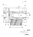
- the work machine 20 includes a conveyance device 30, a mounting head moving device (hereinafter, may be abbreviated as “moving device”) 32, a mounting head 34, and a supply device 36.
- moving device a mounting head moving device
- the transfer device 30 includes a conveyor device 38 and a substrate holding device 40.
- the conveyor device 38 includes a pair of conveyor belts 50 and a plurality of pulleys 52 (see FIG. 3). As shown in FIG. 3, each conveyor belt 50 is wound around a plurality of pulleys 52 and is disposed so as to extend in the X-axis direction.
- the circuit board 54 is supported by the pair of conveyor belts 50.
- FIG. 3 shows only one of the pair of conveyor belts 50.
- one of the plurality of pulleys 52 is rotated by driving an electromagnetic motor (see FIG. 5), so that the conveyor belt 50 rotates. Thereby, the circuit board 54 supported by the pair of conveyor belts 50 is conveyed in the X-axis direction.
- the conveyance direction of the circuit board 54 is a direction from the left to the right in the drawing, and the circulation direction of the conveyor belt 50 when the circuit board 54 is conveyed in the conveyance direction is described as a forward direction.
- a plate-like protrusion 58 is formed on the support surface of the conveyor belt 50 on the side that supports the circuit board 54.
- the substrate holding device 40 includes a pair of elevating plates (only one elevating plate is shown in FIG. 3) 60 and a pair of retaining plates (only one retaining plate is shown in FIG. 3). 62).
- the pair of lifting plates 60 is disposed corresponding to the pair of conveyor belts 50.
- Each elevating plate 60 is disposed inside the corresponding conveyor belt 50 so as to extend in the X-axis direction in a standing state.
- Each lifting plate 60 is slidable in the vertical direction below the circuit board 54 supported by the pair of conveyor belts 50.
- Each lifting plate 60 slides in the vertical direction by driving an electromagnetic motor 66 (see FIG. 5).
- a pair of retaining plates 62 are also disposed corresponding to the pair of conveyor belts 50. Each retaining plate 62 is disposed so as to extend above the corresponding conveyor belt 50. Then, as shown in FIG. 4, the circuit board 54 supported by the conveyor belt 50 is lifted upward by the lifting plate 60, so that the circuit board 54 is sandwiched between the lifting plate 60 and the latch plate 62. Is done. With such a structure, the circuit board 54 is clamped by the board holding device 40, and the mounting operation to the circuit board 54 is performed at the position clamped by the board holding device 40. When the mounting operation on the circuit board 54 is completed, the elevating plate 60 is lowered, and the clamping of the circuit board 54 by the board holding device 40 is released.
- the amount of the circuit board 54 that is lifted by the lifting of the lifting plate 60 from the conveyor belt 50 is longer than the height of the protrusion 58 of the conveyor belt 50. Accordingly, when the circuit board 54 is clamped by the board holding device 40, the conveyor belt 50 can be rotated without causing the circuit board 54 and the protrusion 58 to interfere with each other.
- the conveyance device 30 further includes a detection sensor 68.
- the detection sensor 68 is disposed on the most upstream side of the transport range of the circuit board 54 transported by the conveyor device 38, and at the timing when the circuit board 54 is carried into the work machine 20, the circuit board 54. Is detected. Then, after the circuit board 54 is detected by the detection sensor 68, the conveyor belt 50 is rotated by a predetermined amount, so that the circuit board 54 is conveyed to a clamp position by the board holding device 40.
- the moving device 32 includes an X-axis direction slide mechanism 70 and a Y-axis direction slide mechanism 72 as shown in FIG.
- the X-axis direction slide mechanism 70 has an X-axis slider 76 provided on the base 74 so as to be movable in the X-axis direction.
- the X-axis slider 76 is moved to an arbitrary position in the X-axis direction by driving an electromagnetic motor (see FIG. 5) 77.
- the Y-axis direction slide mechanism 72 has a Y-axis slider 78 provided on the side surface of the X-axis slider 76 so as to be movable in the Y-axis direction.
- the Y-axis slider 78 is moved to an arbitrary position in the Y-axis direction by driving an electromagnetic motor (see FIG. 5) 80.
- the mounting head 34 is attached to the Y-axis slider 78. With such a structure, the mounting head 34 is moved to an arbitrary position on the base 74 by the moving device 32.
- the mounting head 34 mounts electronic components on the circuit board 54.
- the mounting head 34 has a suction nozzle 82 provided on the lower end surface.
- the suction nozzle 82 communicates with a positive / negative pressure supply device (see FIG. 5) 84 via negative pressure air and positive pressure air passages.
- the suction nozzle 82 sucks and holds the electronic component with a negative pressure, and detaches the held electronic component with a positive pressure.
- the supply device 36 is a feeder type supply device, and has a plurality of tape feeders 86.
- the tape feeder 86 accommodates the taped component in a wound state.
- the taped component is a taped electronic component.
- the tape feeder 86 sends out the taped parts by a delivery device 88 (see FIG. 5).
- the feeder type supply device 36 supplies the electronic component at the supply position by feeding the taped component.
- the work machine 20 includes a mark camera (see FIG. 5) 96 and a parts camera (see FIG. 5) 98.
- the mark camera 96 is disposed on the lower surface side of the Y-axis slider 78 of the moving device 32 so as to face downward. Thereby, the mark camera 96 images an arbitrary position of the base 74.
- the parts camera 98 is disposed between the transport device 30 and the supply device 36 so as to face upward. Thereby, the parts camera 98 images the electronic component held by the suction nozzle 82.
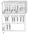
- the work machine 20 includes a control device 100 as shown in FIG.
- the control device 100 includes a controller 102, a plurality of drive circuits 106, and an image processing device 108.
- the plurality of drive circuits 106 are connected to the electromagnetic motors 56, 66, 77, 80, the positive / negative pressure supply device 84, and the delivery device 88.
- the controller 102 includes a CPU, a ROM, a RAM, and the like, mainly a computer, and is connected to a plurality of drive circuits 106. Thereby, the operations of the transport device 30 and the moving device 32 are controlled by the controller 102.
- the controller 102 is also connected to the image processing apparatus 108.
- the image processing apparatus 108 is an apparatus for processing image data captured by the mark camera 96 and the parts camera 98. Thereby, the controller 102 acquires data obtained from the imaging data. Further, the controller 102 is connected to the detection sensor 68 and acquires a detection value by the detection sensor 68.
- the electronic component is mounted on the circuit board 54 with the above-described configuration. Specifically, first, the circuit board 54 is carried into the work machine 20a located on the most upstream side. Then, the circuit board 54 is transported to the clamp position by the conveyor device 38 of the work machine 20a, and is fixedly held by the board holding device 40 at that position. Next, the mark camera 96 moves above the circuit board 54 and images the circuit board 54. Thereby, information regarding the holding position of the circuit board 54 and the like is obtained. Further, the tape feeder 86 sends out the taped parts and supplies the electronic parts at the supply position. Then, the mounting head 34 moves above the supply position of the electronic component, and sucks and holds the electronic component by the suction nozzle 82.
- the mounting head 34 moves above the parts camera 98, and the electronic parts held by the suction nozzle 82 are imaged by the parts camera 98. As a result, information regarding the holding posture of the component can be obtained. Then, the mounting head 34 moves above the circuit board 54, corrects the holding position of the circuit board 54, the holding posture of the electronic component, etc., and mounts the held electronic parts on the circuit board 54.
- the clamp of the circuit board 54 by the board holding device 40 is released, and the circuit board 54 is conveyed to the work machine 20b on the downstream side. Then, in the work machine 20b, the same work as the mounting work is executed.
- circuit board 54 in which the mounting work is completed is transferred from the work machine 20a to the work machine 20b, a new circuit board 54 is carried into the work machine 20a.
- the circuit boards 54 that have been mounted by the respective work machines 20 are sequentially transferred to the work machines 20 on the downstream side, and when the mounting work by all the work machines 20 is completed, the substrate work system 10. Is discharged from the work machine 20h on the most downstream side.
- the circuit board 54 that has been mounted by each work machine 20 is sequentially transferred to the work machine 20 on the downstream side, so that the mounting work on the circuit board is performed.
- the circuit board 54 is not discharged from the downstream working machine 20 and the upstream working machine 20 transports the circuit board to the downstream working machine 20, the circuit boards may interfere with each other. .
- the upstream working machine 20 transports the circuit board to the downstream working machine 20.
- the upstream work machine 20 needs to wait for the circuit board 54 to be discharged by the downstream work machine 20, which may reduce the throughput.
- the circuit board 54 is pushed out toward the work machine 20 on the downstream side by the protrusions 58 of the conveyor belt 50, and the circuit board 54 is simultaneously used in the work machines 20. Is being transported. Specifically, in each work machine 20, as shown in FIG. 6, the circuit board 54 is transported to the work position by the conveyor device 38. Next, in each working machine 20, the circuit board 54 is clamped by being lifted upward by the board holding device 40, and the mounting work on the circuit board 54 is executed. And while the mounting operation
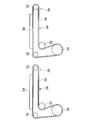
- the conveyor belt 50 is circulated so that the end surface on the opposite side to the conveyance direction of the circuit board 54 and the end surface on the circumferential direction side of the protrusion 58 coincide in the vertical direction. .
- a predetermined distance between the end surface on the opposite side of the conveyance direction of the circuit board 54 and the end surface of the protrusion 58 on the circumferential direction side is predetermined.
- the conveyor belt 50 is circulated so that a clearance (clearance) is formed.
- the position of the protrusion 58 is calibrated before the mounting operation so that the end face of the circuit board 54 opposite to the conveying direction and the end face of the protrusion 58 in the circumferential direction are properly aligned in the vertical direction.
- the conveyor belt 50 is circulated so that the protrusion 58 enters the imaging range of the mark camera 96, and the protrusion 58 is imaged by the mark camera 96.
- the position of the protrusion 58 is calculated based on the imaging data.
- the position of the protrusion 58 is calibrated based on the calculated position of the protrusion 58 and the rotation control position of the electromagnetic motor 56 that rotates the conveyor belt 50.
- the end surface on the opposite side to the conveyance direction of the circuit board 54 and the end surface on the circumferential direction side of the protrusion 58 can be appropriately matched in the vertical direction.
- the circuit board 54 is not simultaneously conveyed in all of the eight work machines 20, and the eight work machines 20 are divided into two groups.
- the circuit board 54 is simultaneously transported every time.
- the eight work machines 20 include a group of work machines 20 on the downstream side of the work machine 20 with the longest installation work time, and upstream work machines 20 including the work machine 20 with the longest installation work time. Divided into groups. In each group, after all the work machines 20 in each group have completed the mounting work and the clamps are released, the circuit boards 54 are conveyed simultaneously.
- the eight working machines 20 are arranged in groups of four adjacent working machines 20a to 20d. And four groups of adjacent working machines 20e to 20h.
- the circuit board 54 is simultaneously transported.
- the circuit board 54 is simultaneously transported for each of the two groups, so that the group of the four working machines 20e to 20h waits for the completion of the mounting work with the work machine 20d having the longest mounting work. There is no need. As a result, the throughput can be further shortened.
- the circuit board 54 is transported, and in the other three work machines 20e to 20g, these three works
- the circuit board 54 may be transported after all the mounting operations of the machines 20e to 20g are completed and the clamp is released. In this way, in the work machine 20h on the most downstream side, the mounting work on the work machine 20h is completed, and the circuit board 54 is immediately transferred, so that the throughput can be further reduced.
- the throughput should be shortened according to the difference between the longest working time in the group of four working machines 20a to 20d and the longest working time in the group of four working machines 20e to 20h. May not be possible.
- the longest work time of a group of four work machines 20a to 20d is 60 seconds
- the longest work time of a group of four work machines 20e to 20h is 50 seconds.
- the difference in working time between the two groups is 10 seconds.
- the transfer time of the circuit board 54 by the transfer device 30 is 5 seconds. In such a case, when the circuit board 54 is simultaneously transported for every two groups, the group of downstream work machines 20e to 20h needs to wait for 5 seconds, which is the transport time of the circuit board 54.
- the group of the downstream work machines 20e to 20h is 10 seconds, which is the difference in work time between the two groups. I need to wait. That is, when the difference in work time between the two groups is longer than the transfer time of the circuit board 54 by the transfer device 30, the circuit board 54 is simultaneously transferred for every two groups, thereby reducing the throughput. It becomes possible.
- the longest working time of the group of four working machines 20a to 20d is 60 seconds and the longest working time of the group of four working machines 20e to 20h is 56 seconds
- the difference in working time between the two groups is 4 seconds.
- the transfer time of the circuit board 54 by the transfer device 30 is 5 seconds.
- the group of downstream work machines 20e to 20h needs to wait for 5 seconds, which is the transport time of the circuit board 54. is there.
- the group of the downstream working machines 20e to 20h is set to 4 seconds, which is the difference in working time between the two groups. I need to wait.
- the controller 102 of the control device 100 includes a rotation control unit 110 and a conveyance control unit 112 as shown in FIG.
- the rotation control unit 110 is a functional unit for rotating the conveyor belt 50 so as to move the protrusion 58 to a position where it can be engaged with the circuit board 54.
- the conveyance control unit 112 is a functional unit for conveying the circuit board 54 in a state in which the protrusions 58 are engaged.
- the on-board working system 10 is an example of the on-board working system.
- the work machine 20 is an example of a substrate work machine.
- the transport device 30 is an example of a transport device.
- the substrate holding device 40 is an example of a clamping device.
- the conveyor belt 50 is an example of a conveyor belt.
- the protrusion 58 is an example of a protrusion.
- the control device 100 is an example of a control device.
- the rotation control unit 110 is an example of a rotation control unit.
- the conveyance control unit 112 is an example of a conveyance control unit.
- this invention is not limited to the said Example, It is possible to implement in the various aspect which gave various change and improvement based on the knowledge of those skilled in the art.
- the conveyor belt 50 is rotated while the circuit board 54 is clamped, and the end surface on the opposite side to the conveying direction of the circuit board 54 and the circumferential direction of the protrusion 58 are rotated.
- the conveyor belt 50 may be rotated so that the protruding portion 58 is positioned upstream of the end surface on the opposite side to the conveying direction of the circuit board 54.
- the protrusion 58 needs to be positioned on the downstream side of the end surface on the conveyance direction side of the circuit board newly carried into the work machine 20.
- the shape of the protrusion 58 is plate-like, but various shapes of the protrusion 58 can be employed as long as the protrusion 58 can be engaged with the circuit board 54.
- one protrusion 58 is formed on the conveyor belt 50, but a plurality of protrusions 58 can be formed.
- the calibration of the position of the projection part 58 is performed based on the imaging data of the projection part 58, the projection part 58 is detected by the detection sensor 68, The detected value is used, The position of the protrusion 58 can be calibrated.
- Anti-substrate work system 20 Work machine (anti-substrate work machine) 30: Transfer device 40: Substrate holding device (clamp device) 50: Conveyor belt 58: Protruding part 100: Control device 110: Rotation control unit 112: Transfer control Part
Abstract
Description
図1に、対基板作業システム10を示す。対基板作業システム10は、回路基板に電子部品を実装するためのシステムである。対基板作業システム10は、8台の作業機20によって構成されている。8台の作業機20は、1列に並んで、隣接した状態で配設されている。なお、以下の説明では、作業機20の並ぶ方向をX軸方向と称し、その方向に直角な水平の方向をY軸方向と称する。また、8台の作業機20を区別する場合には、作業機20a~20hと記載する場合がある。
対基板作業システム10では、上述した構成によって、回路基板54に対する電子部品の装着作業が行われる。具体的には、まず、最も上流側に位置する作業機20aに回路基板54が搬入される。そして、その作業機20aのコンベア装置38により、回路基板54がクランプ位置まで搬送され、その位置において、基板保持装置40によって固定的に保持される。次に、マークカメラ96が、回路基板54の上方に移動し、回路基板54を撮像する。これにより、回路基板54の保持位置等に関する情報が得られる。また、テープフィーダ86は、テープ化部品を送り出し、電子部品を供給位置において供給する。そして、装着ヘッド34が、電子部品の供給位置の上方に移動し、吸着ノズル82によって電子部品を吸着保持する。
上述したように、対基板作業システム10では、各作業機20で装着作業の完了した回路基板54が、順次、下流側の作業機20に搬送されることで、回路基板に対する装着作業が実行される。ただし、下流側の作業機20から回路基板54が排出されていない状態で、上流側の作業機20が下流の側の作業機20に回路基板を搬送すると、回路基板同士が干渉する虞がある。このため、従来の手法では、下流側の作業機20から回路基板54が排出された後に、上流側の作業機20が下流の側の作業機20に回路基板を搬送していた。しかしながら、この従来の手法では、上流側の作業機20が下流側の作業機20による回路基板54の排出を待機する必要があり、スループットが低下する虞がある。
Claims (4)
- 回路基板が載置されるコンベアベルトと、前記コンベアベルト上の回路基板を移動させた状態でクランプするクランプ装置とを有する搬送装置と、
前記搬送装置の作動を制御する制御装置と
を備え、
前記コンベアベルトの載置面に突起部が形成され、
前記制御装置が、
回路基板が前記クランプ装置によってクランプされている間に、クランプが解除された場合の回路基板の搬送方向と反対側の端面の上流側に前記突起部が位置するように、前記コンベアベルトを回転させる回転制御部を有することを特徴とする対基板作業機。 - 前記回転制御部が、
クランプが解除された場合の回路基板の搬送方向と反対側の端面の上流側、かつ、前記対基板作業機に前記搬送装置により新たに搬入される回路基板の搬送方向側の端面の下流側に前記突起部が位置するように、前記コンベアベルトを回転させることを特徴とする請求項1に記載の対基板作業機。 - 前記制御装置が、
回路基板のクランプが解除された後に、回路基板の搬送方向と反対側の端面に前記突起部を掛合させた状態で回路基板を搬送させる搬送制御部を有することを特徴とする請求項1または請求項2に記載の対基板作業機。 - 1列に配列された複数の請求項1ないし請求項3のいずれか1つに記載の対基板作業機を備え、前記複数の対基板作業機の上流側に配置されたものから下流側に配置されたものにわたって搬送される回路基板に対して作業を実行する対基板作業システムであって、
前記制御装置が、
前記複数の対基板作業機のうちの2以上の隣り合う対基板作業機において、回路基板のクランプが解除された後に、同時に回路基板を搬送させる搬送制御部を有することを特徴とする対基板作業システム。
Priority Applications (5)
| Application Number | Priority Date | Filing Date | Title |
|---|---|---|---|
| PCT/JP2015/070259 WO2017009967A1 (ja) | 2015-07-15 | 2015-07-15 | 対基板作業機、および対基板作業システム |
| JP2017528070A JP6539738B2 (ja) | 2015-07-15 | 2015-07-15 | 対基板作業機、および対基板作業システム |
| US15/743,446 US10647510B2 (en) | 2015-07-15 | 2015-07-15 | Board work machine and board work system |
| EP15898279.3A EP3324718B1 (en) | 2015-07-15 | 2015-07-15 | Board working machine and board working system |
| CN201580081484.XA CN107926140B (zh) | 2015-07-15 | 2015-07-15 | 对基板作业机及对基板作业系统 |
Applications Claiming Priority (1)
| Application Number | Priority Date | Filing Date | Title |
|---|---|---|---|
| PCT/JP2015/070259 WO2017009967A1 (ja) | 2015-07-15 | 2015-07-15 | 対基板作業機、および対基板作業システム |
Publications (1)
| Publication Number | Publication Date |
|---|---|
| WO2017009967A1 true WO2017009967A1 (ja) | 2017-01-19 |
Family
ID=57757833
Family Applications (1)
| Application Number | Title | Priority Date | Filing Date |
|---|---|---|---|
| PCT/JP2015/070259 WO2017009967A1 (ja) | 2015-07-15 | 2015-07-15 | 対基板作業機、および対基板作業システム |
Country Status (5)
| Country | Link |
|---|---|
| US (1) | US10647510B2 (ja) |
| EP (1) | EP3324718B1 (ja) |
| JP (1) | JP6539738B2 (ja) |
| CN (1) | CN107926140B (ja) |
| WO (1) | WO2017009967A1 (ja) |
Citations (3)
| Publication number | Priority date | Publication date | Assignee | Title |
|---|---|---|---|---|
| JPH0539124A (ja) * | 1991-08-01 | 1993-02-19 | Matsushita Electric Ind Co Ltd | 回路基板収納装置 |
| JP2008010665A (ja) * | 2006-06-29 | 2008-01-17 | Yamaha Motor Co Ltd | 表面実装機 |
| JP2011199048A (ja) * | 2010-03-19 | 2011-10-06 | Yamaha Motor Co Ltd | 基板搬送装置、基板搬送方法および表面実装機 |
Family Cites Families (28)
| Publication number | Priority date | Publication date | Assignee | Title |
|---|---|---|---|---|
| US3513963A (en) * | 1968-07-01 | 1970-05-26 | Donald H Witte | Conveyor belt for elongated articles |
| DE2061466A1 (de) * | 1970-12-14 | 1972-06-29 | Schmall Automation U Elektroni | Verfahren und Vorrichtung zur Beförderung des Substrats von Schaltungsträgern |
| US4436806A (en) * | 1981-01-16 | 1984-03-13 | W. R. Grace & Co. | Method and apparatus for making printed circuit boards |
| JPS60169148A (ja) * | 1984-02-13 | 1985-09-02 | Dainippon Screen Mfg Co Ltd | 基板の搬送方法及びその装置 |
| JPS61168446A (ja) * | 1985-01-21 | 1986-07-30 | Fuji Kikai Seizo Kk | プリント基板位置決め装置 |
| US4723652A (en) * | 1986-03-17 | 1988-02-09 | Rich Dennis E | Accumulator apparatus for printed circuit boards |
| US4928806A (en) * | 1988-04-08 | 1990-05-29 | Honeywell Inc. | System for removing a pallet from a moving transfer mechanism and for accurately locking the pallet at a precise location |
| US4947980A (en) * | 1989-03-02 | 1990-08-14 | American Telephone And Telegraph Company | Method and apparatus for stopping and clamping substrates |
| US5094584A (en) * | 1989-04-06 | 1992-03-10 | Hewlett-Packard Company | Method and apparatus for automatically changing printed circuit board test fixtures |
| JP3245746B2 (ja) * | 1989-12-08 | 2002-01-15 | エス イー ゲー シュバイツェリッシェ インズストリー‐ゲゼルシャフト | 物品特にチョコレート棒用縦列形成装置 |
| US5115905A (en) * | 1990-06-14 | 1992-05-26 | Compaq Computer Corporation | Magnetically secured conveyor system for printed circuit assemblies |
| JP2517178B2 (ja) * | 1991-03-04 | 1996-07-24 | 松下電器産業株式会社 | 電子部品の実装方法 |
| JPH04131997U (ja) * | 1991-05-29 | 1992-12-04 | 天竜精機株式会社 | 電子部品搭載装置 |
| US6256869B1 (en) * | 1996-07-30 | 2001-07-10 | Fuji Machine Mfg. Co., Ltd. | Electronic-component mounting system |
| US6321904B1 (en) * | 2000-05-04 | 2001-11-27 | Charles L. Mitchell | Conveyor belt with locking member for holder elements |
| US6651461B2 (en) * | 2001-05-31 | 2003-11-25 | 3M Innovative Properties Company | Conveyor belt |
| KR100412273B1 (ko) * | 2001-11-22 | 2003-12-31 | 미래산업 주식회사 | 인쇄회로기판 이송장치 |
| TWI287752B (en) * | 2005-01-31 | 2007-10-01 | All Fine Technology Co Ltd | Composite equipment for automatic marking and reading |
| US20070238565A1 (en) * | 2006-03-27 | 2007-10-11 | Ron Marler | Draper belt having improved durability |
| US20070179002A1 (en) * | 2006-02-01 | 2007-08-02 | Mol Belting Company | Conveyor with roller on belt return span |
| KR100871893B1 (ko) * | 2007-03-09 | 2008-12-05 | 유병석 | 인쇄회로기판의 이송장치 및 그에 사용되는 인쇄회로기판 |
| US20100326797A1 (en) * | 2009-04-23 | 2010-12-30 | Applied Materials, Inc. | Carrier for transporting solar cell substrates |
| JP5597050B2 (ja) * | 2010-07-15 | 2014-10-01 | 富士機械製造株式会社 | 基板停止位置制御方法および装置、ならびに基板装着位置制御方法 |
| JP5780905B2 (ja) * | 2011-09-28 | 2015-09-16 | 富士機械製造株式会社 | 対基板作業システム |
| WO2013124970A1 (ja) * | 2012-02-21 | 2013-08-29 | 富士機械製造株式会社 | 基板搬送装置 |
| JP6180750B2 (ja) * | 2012-02-22 | 2017-08-16 | Juki株式会社 | 対基板作業システム |
| US8839949B2 (en) * | 2012-04-13 | 2014-09-23 | John Bean Technologies Corporation | Determination and correction of conveyor belt speed/location |
| WO2014188513A1 (ja) | 2013-05-21 | 2014-11-27 | ヤマハ発動機株式会社 | 基板の搬送装置、表面実装機、及び基板の搬送方法 |
-
2015
- 2015-07-15 EP EP15898279.3A patent/EP3324718B1/en active Active
- 2015-07-15 US US15/743,446 patent/US10647510B2/en active Active
- 2015-07-15 WO PCT/JP2015/070259 patent/WO2017009967A1/ja active Application Filing
- 2015-07-15 CN CN201580081484.XA patent/CN107926140B/zh active Active
- 2015-07-15 JP JP2017528070A patent/JP6539738B2/ja active Active
Patent Citations (3)
| Publication number | Priority date | Publication date | Assignee | Title |
|---|---|---|---|---|
| JPH0539124A (ja) * | 1991-08-01 | 1993-02-19 | Matsushita Electric Ind Co Ltd | 回路基板収納装置 |
| JP2008010665A (ja) * | 2006-06-29 | 2008-01-17 | Yamaha Motor Co Ltd | 表面実装機 |
| JP2011199048A (ja) * | 2010-03-19 | 2011-10-06 | Yamaha Motor Co Ltd | 基板搬送装置、基板搬送方法および表面実装機 |
Also Published As
| Publication number | Publication date |
|---|---|
| JPWO2017009967A1 (ja) | 2018-04-26 |
| CN107926140B (zh) | 2020-01-03 |
| EP3324718A1 (en) | 2018-05-23 |
| CN107926140A (zh) | 2018-04-17 |
| EP3324718A4 (en) | 2018-07-11 |
| US20180201446A1 (en) | 2018-07-19 |
| JP6539738B2 (ja) | 2019-07-03 |
| EP3324718B1 (en) | 2020-06-10 |
| US10647510B2 (en) | 2020-05-12 |
Similar Documents
| Publication | Publication Date | Title |
|---|---|---|
| JP5003350B2 (ja) | 電子部品実装装置および電子部品実装方法 | |
| JP2009054619A (ja) | 電子部品実装システムおよび電子部品実装方法 | |
| JP2011143640A (ja) | スクリーン印刷装置 | |
| JP6356222B2 (ja) | 部品装着装置 | |
| WO2014013537A1 (ja) | 対基板作業システムおよび作業機 | |
| JP6043871B2 (ja) | 基板の搬送装置、表面実装機、及び基板の搬送方法 | |
| JP7220308B2 (ja) | 対基板作業機 | |
| WO2017009967A1 (ja) | 対基板作業機、および対基板作業システム | |
| JP6204995B2 (ja) | 対基板作業装置 | |
| WO2012176230A1 (ja) | スクリーン印刷装置 | |
| JP5536438B2 (ja) | スクリーン印刷装置 | |
| CN110583102B (zh) | 对基板作业机 | |
| EP3557966B1 (en) | Substrate transfer device | |
| WO2020152766A1 (ja) | 搬送装置 | |
| JP4992871B2 (ja) | 電子部品実装システム | |
| JP7386754B2 (ja) | 部品実装機 | |
| JP5860688B2 (ja) | 対基板作業機 | |
| JP4439706B2 (ja) | 表面実装機および部品実装システム | |
| JP2022118841A (ja) | 作業機、および干渉回避方法 | |
| JP2015038930A (ja) | 部品実装方法及び部品実装装置 | |
| JP2011023684A (ja) | 電子部品実装装置 | |
| JP2019207967A (ja) | 基板搬送装置、印刷機、部品実装機、基板搬送方法 | |
| JP2009071063A (ja) | ヘッドユニットおよび該ヘッドユニットを用いた実装機 |
Legal Events
| Date | Code | Title | Description |
|---|---|---|---|
| 121 | Ep: the epo has been informed by wipo that ep was designated in this application |
Ref document number: 15898279 Country of ref document: EP Kind code of ref document: A1 |
|
| ENP | Entry into the national phase |
Ref document number: 2017528070 Country of ref document: JP Kind code of ref document: A |
|
| WWE | Wipo information: entry into national phase |
Ref document number: 15743446 Country of ref document: US |
|
| NENP | Non-entry into the national phase |
Ref country code: DE |
|
| WWE | Wipo information: entry into national phase |
Ref document number: 2015898279 Country of ref document: EP |