WO2017008454A1 - 一种机器人的定位方法 - Google Patents
一种机器人的定位方法 Download PDFInfo
- Publication number
- WO2017008454A1 WO2017008454A1 PCT/CN2015/099467 CN2015099467W WO2017008454A1 WO 2017008454 A1 WO2017008454 A1 WO 2017008454A1 CN 2015099467 W CN2015099467 W CN 2015099467W WO 2017008454 A1 WO2017008454 A1 WO 2017008454A1
- Authority
- WO
- WIPO (PCT)
- Prior art keywords
- robot
- filter
- information
- orientation data
- local filter
- Prior art date
- Legal status (The legal status is an assumption and is not a legal conclusion. Google has not performed a legal analysis and makes no representation as to the accuracy of the status listed.)
- Ceased
Links
Images



Classifications
-
- G—PHYSICS
- G01—MEASURING; TESTING
- G01C—MEASURING DISTANCES, LEVELS OR BEARINGS; SURVEYING; NAVIGATION; GYROSCOPIC INSTRUMENTS; PHOTOGRAMMETRY OR VIDEOGRAMMETRY
- G01C11/00—Photogrammetry or videogrammetry, e.g. stereogrammetry; Photographic surveying
- G01C11/04—Interpretation of pictures
- G01C11/06—Interpretation of pictures by comparison of two or more pictures of the same area
- G01C11/08—Interpretation of pictures by comparison of two or more pictures of the same area the pictures not being supported in the same relative position as when they were taken
-
- A—HUMAN NECESSITIES
- A47—FURNITURE; DOMESTIC ARTICLES OR APPLIANCES; COFFEE MILLS; SPICE MILLS; SUCTION CLEANERS IN GENERAL
- A47L—DOMESTIC WASHING OR CLEANING; SUCTION CLEANERS IN GENERAL
- A47L11/00—Machines for cleaning floors, carpets, furniture, walls, or wall coverings
- A47L11/40—Parts or details of machines not provided for in groups A47L11/02 - A47L11/38, or not restricted to one of these groups, e.g. handles, arrangements of switches, skirts, buffers, levers
-
- G—PHYSICS
- G01—MEASURING; TESTING
- G01C—MEASURING DISTANCES, LEVELS OR BEARINGS; SURVEYING; NAVIGATION; GYROSCOPIC INSTRUMENTS; PHOTOGRAMMETRY OR VIDEOGRAMMETRY
- G01C23/00—Combined instruments indicating more than one navigational value, e.g. for aircraft; Combined measuring devices for measuring two or more variables of movement, e.g. distance, speed or acceleration
-
- G—PHYSICS
- G01—MEASURING; TESTING
- G01S—RADIO DIRECTION-FINDING; RADIO NAVIGATION; DETERMINING DISTANCE OR VELOCITY BY USE OF RADIO WAVES; LOCATING OR PRESENCE-DETECTING BY USE OF THE REFLECTION OR RERADIATION OF RADIO WAVES; ANALOGOUS ARRANGEMENTS USING OTHER WAVES
- G01S17/00—Systems using the reflection or reradiation of electromagnetic waves other than radio waves, e.g. lidar systems
- G01S17/02—Systems using the reflection of electromagnetic waves other than radio waves
- G01S17/06—Systems determining position data of a target
- G01S17/46—Indirect determination of position data
- G01S17/48—Active triangulation systems, i.e. using the transmission and reflection of electromagnetic waves other than radio waves
-
- G—PHYSICS
- G05—CONTROLLING; REGULATING
- G05D—SYSTEMS FOR CONTROLLING OR REGULATING NON-ELECTRIC VARIABLES
- G05D1/00—Control of position, course, altitude or attitude of land, water, air or space vehicles, e.g. using automatic pilots
- G05D1/02—Control of position or course in two dimensions
-
- H—ELECTRICITY
- H03—ELECTRONIC CIRCUITRY
- H03H—IMPEDANCE NETWORKS, e.g. RESONANT CIRCUITS; RESONATORS
- H03H17/00—Networks using digital techniques
- H03H17/02—Frequency selective networks
- H03H17/0248—Filters characterised by a particular frequency response or filtering method
- H03H17/0255—Filters based on statistics
- H03H17/0257—KALMAN filters
-
- H—ELECTRICITY
- H03—ELECTRONIC CIRCUITRY
- H03H—IMPEDANCE NETWORKS, e.g. RESONANT CIRCUITS; RESONATORS
- H03H17/00—Networks using digital techniques
- H03H17/02—Frequency selective networks
- H03H17/0202—Two or more dimensional filters; Filters for complex signals
- H03H2017/0205—Kalman filters
Definitions
- the present invention relates to the field of robot technology, and in particular, to a method for positioning a robot.
- the positioning and navigation technology of indoor cleaning robots is a key research hotspot in the field of service robot research.
- positioning and navigation technology is the key to realize intelligent and fully autonomous movement of mobile robots. For navigation, it is to let the robot identify the strange environment independently and identify its own relative position without external human intervention, so as to accurately move to the specified target position and complete the designated work task.
- For the sweeping robot it is to accurately complete the cleaning task according to the established sweeping path and strategy.
- the common positioning technology of sweeping robots is as follows:
- Patent application A sweeping robot intelligent navigation system, application number: 201310087158.2
- a base station is placed indoors.
- An infrared transmitting head and a noise wave transmitting head are installed on the base station, and then an infrared receiving head and a noise wave receiving head are installed on the cleaning robot.
- the robot calculates the distance by receiving the infrared and acoustic signals transmitted by the base station to achieve the purpose of positioning. The requirement is that the trajectory of the robot motion must always be perpendicular to the base station.
- the infrared locating technology of the technical solution is susceptible to the occlusion of the infrared signal, and the distance is affected by the signal intensity distribution, so that the positioning is not reliable.
- the technology mainly designs an encoder disk.
- the Hall sensor and the multi-pole magnetic ring are mounted on the wheel to form an electromagnetic induction system.
- the Hall sensor can generate current, and the processor determines the wheel by the magnitude of the current. Speed and number of revolutions. Then, the cumulative speed is used to achieve the purpose of robot positioning.
- the locating technology based on the odometer is relatively easy to implement, it has the problem of accumulated error, which will affect the positioning accuracy of the robot after a long time of work.
- Patent Application (3) A vision-based robot indoor positioning navigation method.
- the visual positioning method of the technical solution may need to change the appearance of the original indoor environment.
- the algorithm has low reliability, poor anti-interference ability, high performance requirement on the processor, and high cost.
- Patent application (4) Earth-moving robot obstacle avoidance, positioning system and method.
- a nine-segment collision detector is introduced. Since there are many collision detectors around the robot, it is possible to detect collisions at multiple angles, which is helpful for obstacle avoidance and positioning. Then, in terms of distance calculation, the Hall sensor is used to encode the wheel speed, and the accumulated speed constitutes an odometer.
- the technical solution based on collision avoidance is very blunt and not intelligent, and the long-term use of the collision detector may cause mechanical damage and affect reliability.
- the laser sensor-based positioning technology has attracted much attention in the navigation field due to its high precision and strong data reliability.
- the large size of the laser sensor is inconvenient to install on small indoor robots, and the data volume is inconvenient to handle. The point is that it is expensive and has not yet been promoted in home service robot applications.
- GPS technology is widely used in the navigation field, but it has no signal indoors and is not suitable for indoor robot positioning.
- the present invention provides a positioning method of a robot, which can make the positioning accuracy of the robot moving while being low, and the cost is low.
- the present invention provides a method for positioning a robot, the method comprising:
- the corresponding orientation data is collected by the photoelectric image sensor, the position sensitive sensor, the odometer and the gyroscope;
- the orientation data collected by the photoelectric image sensor is input to the first local filter, the second local filter, the third local filter, and the main filter; the orientation data collected by the position sensitive sensor is input to the first local filter.
- the first local filter processes the orientation data collected by the photoelectric image sensor and the orientation data collected by the position sensitive sensor according to the latest information fed back by the main filter, and inputs the processing result to the main filter;
- the odometer collects The orientation data is input to a second local filter; the second local filter is based on the most feedback of the main filter
- the new positioning information processes the orientation data collected by the photoelectric image sensor and the orientation data collected by the odometer, and inputs the processing result to the main filter;
- the orientation data collected by the gyroscope is input to the third local filter;
- the local filter processes the orientation data collected by the photoelectric image sensor and the orientation data collected by the gyroscope according to the latest information fed back by the main filter, and inputs the processing result to the main filter;
- the main filter processes data output by the photoelectric image sensor, data output by the first local filter, data output by the second local filter, and data output by the third local filter to obtain positioning information of the robot; Information is fed back to the first local filter, the second local filter, and the third local filter.
- the technical solution adopts the photoelectric image sensor, has low cost, reliable data, and low requirements on processor performance. Further, the technical solution combines the information of the four sensors of the photoelectric image sensor, the position sensitive sensor, the odometer and the gyroscope, so that the positioning error does not accumulate and the positioning accuracy is high; and there is no need to arrange any road signs indoors, and the robot There is no limit to the path of motion.
- the technical solution adopts a position sensitive sensor, and can simultaneously realize the functions of obstacle avoidance and returning to the charging station.
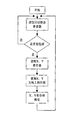
- FIG. 1 is a flow chart of a positioning method of a robot according to the present invention.
- Figure 2 is a top view of the position of the photoelectric image sensor
- 3 is a flow chart of acquiring data collected by each sensor by the host computer software of the robot;
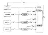
- FIG. 4 is a schematic structural diagram of a joint Kalman filter algorithm according to the present invention.
- FIG. 5 is a schematic diagram of the distance measurement of the position sensitive sensor of the present invention.
- the working principle of this technical solution is: Most robots are faced with various size problems, such as price and positioning error; in addition, indoor moving objects affect the original algorithm of the robot; The person needs to deploy a lot of sensors and accessories in the room, which changes the original appearance of the room, and it is not what we want. With these defects in mind, we have proposed a better approach.
- the technical solution adopts a lower cost sensor, combines the data of each sensor, overcomes the respective deficiencies, and makes the positioning more accurate. Another is its energy efficiency. Due to the high quality positioning navigation, he will not go back and forth in the same place, so that it does not need to be recharged for a long time.
- the technical solution adopts the photoelectric image sensor as the main motion parameter measuring unit, and integrates it with the data of the odometer, the gyroscope and the position sensitive sensor to increase the reliability thereof. Since the photoelectric image sensor data is not affected by the drift of the robot, it is not easy to generate cumulative errors, and it is installed under the robot, and is not interfered by the moving object, and can provide accurate motion data to perform positioning calculation to the utmost. In order to realize the intelligent obstacle avoidance of the robot, the technical solution is based on the position sensitive sensor distance measuring system, which enables the robot to perceive obstacles in a large range and make an obstacle avoidance strategy.
- the present invention proposes a positioning method of a robot. As shown in Figure 1.
- the method includes:
- Step 103) the main filter processes the data output by the photoelectric image sensor, the data output by the first local filter, the data output by the second local filter, and the data output by the third local filter to obtain the positioning of the robot. Information; at the same time, information is fed back to the first local filter, the second local filter, and the third local filter.
- FIG. 2 it is a top view of the position of the photoelectric image sensor.
- the photoelectric image sensor is used as the main robot motion parameter sensing unit.
- the photoelectric image sensor 1 is mounted at the bottom of the robot body 2 and between the robot wheels 3. Bring it close to the ground. Transfer the information received by the sensor to the host computer of the robot through the serial port.
- Software, the PC software extracts the displacement and direction data of the robot motion, and then applies to the indoor positioning of the robot.
- the photoelectric image sensor obtains the distance and direction of the robot movement by comparing the difference between the two images.
- a flow chart of data collected by each sensor is acquired for the host computer software of the robot.
- the displacement information detected by the sensor is placed in the corresponding X, Y register, and an X, Y register is read for each distance to prevent register overflow.
- the internal motion status register marks whether the sensor generates displacement. If there is no displacement, the value of the motion status register is circulated continuously; if a displacement is generated, the values of the X and Y registers are read, and the values in the X and Y directions are accumulated and saved. . Then clear the X, Y registers, continue to read the motion status register, and so on.
- the technical solution uses various sensors such as photoelectric image sensors, position sensitive sensors, odometers, gyroscopes, etc.
- the output data of various sensors is different in form, and these data must be converted into a unified standard, and the data of the multi-sensor is used for the target.
- State estimation looking for a state vector that best fits the observed data.
- the technical solution adopts the structure of the joint Kalman filter to fuse various sensor data.
- the local filter is filtered according to the state equation and the measurement equation, and the filtering result of each step is transmitted to the main filter, and the main filter completes the optimal synthesis of the information to form a comprehensive information of the global system.
- P g The global estimate of the synthesis by the main filter after each filtering phase is completed
- P g the information distribution amount formed by the main filter according to the information distribution principle is fed back to each local filter.
- the system covariance matrix is Q i
- the state estimation vector, system covariance matrix and state vector covariance matrix of the main filter are: P g , Q g .
- the calculation process of the joint Kalman filter is as follows (1) to (11):
- the system covariance matrix is Q 0
- the state vector covariance matrix is P 0 . This information is regularly distributed to the local filters and global filters by the information distribution factor.
- the measurement of the i-th local filter is updated to:
- the joint Kalman filter is an ideal method.
- the basic idea of the joint Kalman filter design is: first decentralized processing, then global fusion, that is, selecting a subsystem with comprehensive information, high output rate and reliable reliability as a common reference system among many non-similar subsystems, and other The subsystems are combined in pairs to form several sub-filters.
- the common reference system is a photoelectric image sensor.
- the technical solution adopts a fusion reset structure.
- each subsystem is sent to the main filter after Kalman filtering, and the main filter only completes the synthesis of the local filtering information without filtering.
- the main filter state equation has no information distribution, so The estimated value of the main filter is taken as a global estimate. which is:
- FIG. 4 is a schematic structural diagram of a joint Kalman filter algorithm according to the present invention.
- the state vector of the joint Kalman filter be X g
- the variance matrix P g the state vector of the local filter
- the variance matrix be P i
- the state vector of the main filter be X m
- the variance matrix be P m
- the measurement information is measured by the inverse R -1 of the noise variance matrix.
- the system information is represented by the inverse Q -1 of the system noise variance matrix
- the filtered estimation error information is represented by the inverse P -1 of the estimated error variance matrix.
- the fusion algorithm of the present technical solution includes four filters, namely a main filter, a local filter 1, a local filter 2, and a local filter 3.
- the local filter 1 is responsible for the information collected by the position sensitive sensor and the information collected by the photoelectric image sensor; the local filter 2 is responsible for the information collected by the photoelectric image sensor and the information collected by the odometer; the local filter 3 is responsible for the photoelectric image sensor acquisition.
- the information is combined with the information collected by the gyroscope.
- the main filter performs information synthesis and distribution on each local filter, and on the other hand, the estimated value of the system state error is fed back to each local filter to correct its accumulated error.
- the overall system information is distributed among the filters according to the following rules:
- ⁇ i represents the information distribution coefficient of the i-th filter
- the positioning information of the robot is the position information e of the robot in the longitude direction, the speed information v e of the robot in the longitude direction, the acceleration information a e of the robot in the longitude direction, and the robot in the latitude direction.
- the method further comprises:
- the obstacle avoidance strategy is obtained by using the distance between the front of the robot and the obstacle and the moving speed of the robot.
- FIG. 5 is a schematic diagram of distance measurement of the position sensitive sensor of the present invention.
- Two equal focal length converging lenses 13 are mounted in front of the robot, and two position sensitive sensors 14 are respectively located at the focal points of the two converging lenses 13, which are in line with the light source 12.
- X1, x2 are the positions of the photosensitive region of the position sensitive sensor 14 after the obstacle 11 reflects the light passing through the condenser lens; l is the distance between the two position sensitive sensors 14; y is the distance from the obstacle to the front of the robot.
- the relative speed is also available:
- y n is the distance between the vehicle and the obstacle at time n
- y n-1 is the distance between the vehicle and the obstacle at time n-1
- t n -t n-1 is the time difference between the two distances.
- the robot moves to the target position using the positioning information of the robot and the obstacle avoidance strategy.
- the technical solution realizes accurate autonomous navigation of the robot indoors, and efficiently completes the cleaning task.
- home cleaning robots now have no ability to move to all corners of the house without repeating them. It is very likely that they will move back and forth to the same area over and over again.
- the technical solution enables the robot to be accurately positioned, so that the robot can avoid repeated paths, thereby saving energy and saving cleaning time.
Landscapes
- Engineering & Computer Science (AREA)
- Physics & Mathematics (AREA)
- Remote Sensing (AREA)
- Radar, Positioning & Navigation (AREA)
- General Physics & Mathematics (AREA)
- Electromagnetism (AREA)
- Aviation & Aerospace Engineering (AREA)
- Probability & Statistics with Applications (AREA)
- Computer Hardware Design (AREA)
- Mathematical Physics (AREA)
- Multimedia (AREA)
- Computer Networks & Wireless Communication (AREA)
- Automation & Control Theory (AREA)
- Navigation (AREA)
- Control Of Position, Course, Altitude, Or Attitude Of Moving Bodies (AREA)
Abstract
一种机器人的定位方法,包括:机器人移动时通过光电图像传感器、位置敏感传感器、里程计和陀螺仪采集方位数据(201);光电图像传感器采集的方位数据输入至所有局部滤波器和主滤波器;位置敏感传感器采集的方位数据输入至第一局部滤波器;第一局部滤波器对输入的方位数据进行处理,将处理结果输入至主滤波器;里程计采集的方位数据输入至第二局部滤波器;第二局部滤波器对输入的方位数据进行处理,将处理结果输入至主滤波器;陀螺仪采集的方位数据输入至第三局部滤波器;第三局部滤波器对输入的方位数据进行处理,将处理结果输入至主滤波器(202);主滤波器对光电图像传感器输出的数据、所有局部滤波器输出的数据进行处理,获得机器人的定位信息(203)。
Description
本申请要求2015年07月10日递交的申请号为201510403964.5、发明名称为“一种机器人的定位方法”的中国专利申请的优先权,其全部内容通过引用结合在本申请中。
本发明涉及机器人技术领域,特别涉及一种机器人的定位方法。
室内清洁机器人的定位导航技术是服务机器人研究领域的一个重点研究热点。在相关技术研究中,定位与导航技术是移动机器人实现智能化和完全自主移动的关键。对于导航来说,就是让机器人在没有外界人为干预的情况下,自主识别陌生环境,识别自身的相对位置,从而准确运动到达指定的目标位置,完成指定工作任务。对于扫地机器人来说,就是准确地按照制定的扫地路径、策略完成清扫任务。目前,扫地机器人常用的定位技术如下:
专利申请(1)一种扫地机器人智能导航系统,申请号:201310087158.2
它是采用红外技术设计的一种室内定位方案,在室内安放一个基站,基站上面安装了红外发射头和噪声波发射头,然后在扫地机器人上面安装红外接收头和噪声波接收头。机器人通过接受基站发射的红外和声波信号来计算距离从而达到定位的目的,要求是机器人运动的轨迹必须始终垂直基站。
本技术方案基于红外的定位技术由于红外信号容易受障碍物遮挡影响,并且距离远近影响其信号强度分布,使得其定位并不可靠。
专利申请(2)基于万向轮的扫地机器人测速、测距系统及方法,申请号:201410266593.6
该技术主要是设计了一种编码盘,通过在车轮上安装霍尔传感器和多极磁环来构成电磁感应系统,车轮旋转时可以使霍尔传感器产生电流,处理器通过电流的大小来判定车轮的转速和转数。然后也是通过累计转速来达到机器人定位的目的。
本技术方案基于里程计的定位技术虽然比较容易实现,但其存在累积误差的问题,长时间工作后会影响机器人的定位准确性。
专利申请(3)一种基于视觉的机器人室内定位导航方法。申请号:201010611473.7
它是一种基于视觉的机器人室内定位导航方法,根据二维码的思路,设计一种简单方便、易于识别、内含绝对位置坐标且具有一定纠错能力的人工路标,将路标设置于天花板上,由安装在机器人上且光轴与天花板垂直的摄像机进行拍摄,再通过图像的阈值分割、连通域提取、轮廓曲线匹配以及路标特征识别一系列步骤定位路标,解析路标中所包含的坐标信息,最终通过机器人的位置估计算法获得机器人当前的绝对位置和航向角。
本技术方案基于视觉的定位方式一方面可能需要改变原来室内环境的外貌,另一方面算法可靠性较低,抗干扰能力差,且对处理器的性能要求较高,成本较高。
专利申请(4)扫地机器人避障、定位系统及方法。申请号:201410266597.4
介绍了一种九段碰撞检测器,由于机器人周身的碰撞检测器较多,因此可以检测到多个角度的碰撞,对避障和定位有一定的帮助。然后距离计算方面,采用霍尔传感器对车轮转速进行编码,累加转速构成里程计。
本技术方案基于碰撞的避障方式显得非常生硬不够智能,并且碰撞检测器长期使用可能存在机械损坏的问题,影响可靠性。
此外,基于激光传感器的定位技术由于其精度高、数据可靠性强等优点使得其在导航领域很受关注,但是激光传感器体积较大不方便安装在室内小型机器人上,数据量大不方便处理,重点是其价格昂贵,目前尚未在家庭服务机器人应用中推广。GPS技术在导航领域中应用较广,但是其在室内没有信号,并不适用于室内机器人的定位。
发明内容
为解决现有技术的问题,本发明提出一种机器人的定位方法,该方法能够使得机器人移动时定位准确度高,且成本低。
为实现上述目的,本发明提供了一种机器人的定位方法,该方法包括:
所述机器人移动时通过光电图像传感器、位置敏感传感器、里程计和陀螺仪采集相应的方位数据;
所述光电图像传感器采集的方位数据均输入至第一局部滤波器、第二局部滤波器、第三局部滤波器和主滤波器;所述位置敏感传感器采集的方位数据输入至第一局部滤波器;所述第一局部滤波器根据主滤波器反馈的最新信息对光电图像传感器采集的方位数据和位置敏感传感器采集的方位数据进行处理,将处理结果输入至主滤波器;所述里程计采集的方位数据输入至第二局部滤波器;所述第二局部滤波器根据主滤波器反馈的最
新定位信息对光电图像传感器采集的方位数据和里程计采集的方位数据进行处理,将处理结果输入至主滤波器;所述陀螺仪采集的方位数据输入至第三局部滤波器;所述第三局部滤波器根据主滤波器反馈的最新信息对光电图像传感器采集的方位数据和陀螺仪采集的方位数据进行处理,将处理结果输入至主滤波器;
所述主滤波器对光电图像传感器输出的数据、第一局部滤波器输出的数据、第二局部滤波器输出的数据和第三局部滤波器输出的数据进行处理,获得机器人的定位信息;同时,向第一局部滤波器、第二局部滤波器和第三局部滤波器反馈信息。
上述技术方案具有如下有益效果:本技术方案采用光电图像传感器,成本低,数据可靠,对处理器性能要求低。进一步地,本技术方案对光电图像传感器、位置敏感传感器、里程计和陀螺仪这四种传感器的信息进行融合,使得定位误差不积累,定位精度较高;且无需在室内布置任何路标,对机器人的运动路径没有限制。
另外,本技术方案采用位置敏感传感器,能同时实现避障和返回充电站的功能。
为了更清楚地说明本发明实施例中的技术方案,下面将对实施例描述中所需要使用的附图作简单地介绍,显而易见地,下面描述中的附图仅仅是本发明的一些实施例,对于本领域普通技术人员来讲,在不付出创造性劳动的前提下,还可以根据这些附图获得其他的附图。在附图中:
图1为本发明提出的一种机器人的定位方法流程图;
图2为光电图像传感器位置俯视图;
图3为机器人的上位机软件获取各传感器采集的数据流程图;
图4为本发明的联合卡尔曼滤波算法结构示意图;
图5为本发明的位置敏感传感器的测距示意图。
为使本发明实施例的目的、技术方案和优点更加清楚明白,下面结合附图对本发明实施例做进一步详细说明。在此,本发明的示意性实施例及其说明用于解释本发明,但并不作为对本发明的限定。
本技术方案的工作原理为:大多数机器人都面临着各种各样的大小问题,比如:价格、定位误差等问题;另外,室内的运动物体影响机器人原有算法的发挥;还有一些机
器人需要部署许多传感器和附件在房间,这样改变了房间原貌,而且也不是我们希望的。考虑到这些缺陷,我们提出了更好的方法。本技术方案采用成本较低的传感器,融合各传感器的数据,克服各自的不足,使定位更加准确。还有一个是它的能源效率,由于高质量的定位导航,他不会去同一个地方来回重复移动,使得它长时间工作不需要充电。
本技术方案采用光电图像传感器作为主要的运动参数测量单元,将其与里程计、陀螺仪、位置敏感传感器的数据进行融合,增加其可靠性。由于光电图像传感器数据不受机器人漂移影响、不容易产生累积误差,并且其安装在机器人下方,不受运动物体的干扰,能最大限度地提供准确的运动数据去进行定位运算。为了实现机器人的智能避障,本技术方案基于位置敏感传感器的距离测量系统,能让机器人在较大的范围内感知障碍物,做出避障策略。
基于上述工作原理,本发明提出一种机器人的定位方法。如图1所示。该方法包括:
步骤101):所述机器人移动时通过光电图像传感器、位置敏感传感器、里程计和陀螺仪采集相应的方位数据;
步骤102):所述光电图像传感器采集的方位数据均输入至第一局部滤波器、第二局部滤波器、第三局部滤波器和主滤波器;所述位置敏感传感器采集的方位数据输入至第一局部滤波器;所述第一局部滤波器根据主滤波器反馈的最新信息对光电图像传感器采集的方位数据和位置敏感传感器采集的方位数据进行处理,将处理结果输入至主滤波器;所述里程计采集的方位数据输入至第二局部滤波器;所述第二局部滤波器根据主滤波器反馈的最新定位信息对光电图像传感器采集的方位数据和里程计采集的方位数据进行处理,将处理结果输入至主滤波器;所述陀螺仪采集的方位数据输入至第三局部滤波器;所述第三局部滤波器根据主滤波器反馈的最新信息对光电图像传感器采集的方位数据和陀螺仪采集的方位数据进行处理,将处理结果输入至主滤波器;
步骤103):所述主滤波器对光电图像传感器输出的数据、第一局部滤波器输出的数据、第二局部滤波器输出的数据和第三局部滤波器输出的数据进行处理,获得机器人的定位信息;同时,向第一局部滤波器、第二局部滤波器和第三局部滤波器反馈信息。
如图2所示,为光电图像传感器位置俯视图。采用光电图像传感器作为主要的机器人运动参数感知单元。把光电图像传感器1安装在机器人机身2的底部,并且位于机器人轮子3之间。使其靠近地面。将传感器接受到的信息通过串口传输给机器人的上位机
软件,上位机软件提取机器人运动的位移和方向数据,然后应用于机器人的室内定位。光电图像传感器通过比较两幅图像的差别来得到机器人移动的距离和方向。
如图3所示,为机器人的上位机软件获取各传感器采集的数据流程图。传感器检测到的位移信息放在对应的X、Y寄存器里,每移动一段距离读取一X、Y寄存器,防止寄存器溢出。内部运动状态寄存器标记传感器是否产生位移,如果没有位移,则一直循环查询运动状态寄存器的值;如果产生了位移,则读取X、Y寄存器的值,分别累加X、Y方向上的值并保存。然后对X、Y寄存器清零,继续读取运动状态寄存器,如此循环。
本技术方案使用了光电图像传感器、位置敏感传感器、里程计、陀螺仪等多种传感器,各种传感器的输出数据的形式不同,必须将这些数据转换成统一的标准,利用多传感器的数据进行目标的状态估计,寻找到与观测数据最佳拟合的状态向量。本技术方案采用联合卡尔曼滤波器的结构对各种传感器数据进行融合。
局部滤波器根据状态方程和测量方程进行滤波,并将每步的滤波结果传递给主滤波器,主滤波器完成信息的最优综合,形成全局系统的综合信息 Pg。每个滤波阶段完成后,由主滤波器将合成的全局估计
 和Pg。同时,主滤波器按照信息分配原则形成的信息分配量,反馈给各个局部滤波器。
记局部滤波器i的状态估计矢量为 系统协方差阵为Qi,状态矢量协方差阵为Pi,其中i=1……N。主滤波器的状态估计矢量、系统协方差阵和状态矢量协方差阵相应为:
 Pg、Qg。联合卡尔曼滤波器的计算过程如下式(1)~式(11):
a.给定初始值:
假设起始时刻全局状态的初始值为X0,系统协方差阵为Q0,状态矢量协方差阵为P0将这一信息通过信息分配因子按规则分配到各局部滤波器和全局滤波器。


其中,βi满足信息守恒原则β1+β2+……+βN+βm=1,0≤βi≤1。
b.信息的时间更新情况为:
Xi,(k|k-1)=Φk|k-1Xi,(k-1) (6)

c.信息的量测更新时,第i个局部滤波器的量测更新为:


d.最优信息融合符合下式:


联合卡尔曼滤波器是一种理想的方法。联合卡尔曼滤波器设计的基本思想是:先分散处理,再全局融合,即在诸多非相似子系统中选择一个信息全面、输出速率高、可靠性有保证的子系统作为公共参考系统,与其他子系统两两结合,形成若干子滤波器。
对于本技术方案来说,公共参考系统为光电图像传感器。为了兼顾系统的精确度和容错性,本技术方案采用融合复位结构。此种结构中,各个子系统分别经过卡尔曼滤波后送入主滤波器,主滤波器只完成对局部滤波信息的综合,而不进行滤波处理,此时主滤波器状态方程无信息分配,所以主滤波器的估计值就取全局估计。即:

如图4所示,为本发明的联合卡尔曼滤波算法结构示意图。设联合卡尔曼滤波器的状态向量为Xg,方差阵Pg,局部滤波器的状态向量为Xi,其方差阵为Pi,主滤波器的状态向量为Xm,方差阵为Pm,测量信息用量测噪声方差阵的逆R-1来表示,系统信息用系统噪声方差阵的逆Q-1来表示,滤波估计误差信息用估计误差方差阵的逆P-1来表示。本技术方案的融合算法包括4个滤波器,即主滤波器、局部滤波器1,局部滤波器2,局部滤
波器3。其中,局部滤波器1负责位置敏感传感器采集的信息与光电图像传感器采集的信息融合;局部滤波器2负责光电图像传感器采集的信息与里程计采集的信息融合;局部滤波器3负责光电图像传感器采集的信息和陀螺仪采集的信息融合。主滤波器一方面对各局部滤波器进行信息综合与分配,另一方面将系统状态误差的估计值反馈给各个局部滤波器,以校正其累积误差。
在图4中,采用的是融合复位结构,于是有:
β1=β2=β3=1/3
那么,在联合滤波结构中,系统整体信息按以下的规则在各滤波器间分配:
各滤波模型的过程噪声方差也按同样规则分配:
Xi=Xm=Xg


式中,βi表示第i个滤波器的信息分配系数;
当各个局部滤波器和主滤波器的解是统计独立时,它们可以按照下面的算法进行最优合成:


对于本实施来说,所述机器人的定位信息为机器人在经度方向上的位置信息e、机器人在经度方向上的速度信息ve、机器人在经度方向上的加速度信息ae、机器人在纬度方向上的位置信息n、机器人在纬度方向上的速度信息vn、机器人在纬度方向上的加速度信息an、机器人的姿态信息θ和/或机器人的转速信息ω。
优选地,还包括:
对所述位置敏感传感器采集到的方位信息运用三角形相似原理获得机器人正前方与障碍物之间的距离,并同时获取机器人的移动速度;
利用机器人正前方与障碍物之间的距离、机器人的移动速度获取避障策略。
如图5所示,为本发明的位置敏感传感器的测距示意图。运用三角形原理测量机器人前部与障碍物之间的距离。将两个等焦距的会聚透镜13安装于机器人前方,两个位置敏感传感器14分别位于两个会聚透镜13的焦点上,两透镜与光源12在同一直线上。x1、x2为障碍物11反射光经过会聚透镜后落在位置敏感传感器14的光敏区域位置;l为两个位置敏感传感器14之间的距离;y为障碍物到机器人前部的距离。
根据图中相似三角形关系可得:


式(1)+(2)得

因为l1+l2=l,所以
又可得到相对速度:

上式中,yn为n时刻本车与障碍物间距离,yn-1为n-1时刻本车与障碍物间距离,tn-tn-1为两次测距的时间差。
对于本实施例来说,机器人利用机器人的定位信息和避障策略移动至目标位置。本技术方案实现机器人在室内的准确自主导航,高效的完成清扫任务。一般来说,现在家用清洁机器人还没有能力不重复的移动到屋内空间的各个角落,很有可能会一遍又一遍地到相同区域来回移动清扫。本技术方案能够让机器人准确定位,使得机器人能够避免重复路径,从而节约能源、节省清扫时间。
以上所述的具体实施方式,对本发明的目的、技术方案和有益效果进行了进一步详细说明,所应理解的是,以上所述仅为本发明的具体实施方式而已,并不用于限定本发明的保护范围,凡在本发明的精神和原则之内,所做的任何修改、等同替换、改进等,均应包含在本发明的保护范围之内。
Claims (6)
- 一种机器人的定位方法,其特征在于,该方法包括:所述机器人移动时通过光电图像传感器、位置敏感传感器、里程计和陀螺仪采集相应的方位数据;所述光电图像传感器采集的方位数据均输入至第一局部滤波器、第二局部滤波器、第三局部滤波器和主滤波器;所述位置敏感传感器采集的方位数据输入至第一局部滤波器;所述第一局部滤波器根据主滤波器反馈的最新信息对光电图像传感器采集的方位数据和位置敏感传感器采集的方位数据进行处理,将处理结果输入至主滤波器;所述里程计采集的方位数据输入至第二局部滤波器;所述第二局部滤波器根据主滤波器反馈的最新定位信息对光电图像传感器采集的方位数据和里程计采集的方位数据进行处理,将处理结果输入至主滤波器;所述陀螺仪采集的方位数据输入至第三局部滤波器;所述第三局部滤波器根据主滤波器反馈的最新信息对光电图像传感器采集的方位数据和陀螺仪采集的方位数据进行处理,将处理结果输入至主滤波器;所述主滤波器对光电图像传感器输出的数据、第一局部滤波器输出的数据、第二局部滤波器输出的数据和第三局部滤波器输出的数据进行融合,获得机器人的定位信息;同时,向第一局部滤波器、第二局部滤波器和第三局部滤波器反馈信息。
- 如权利要求1所述的方法,其特征在于,所述机器人的定位信息为机器人在经度方向上的位置信息e、机器人在经度方向上的速度信息ve、机器人在经度方向上的加速度信息ae、机器人在纬度方向上的位置信息n、机器人在纬度方向上的速度信息vn、机器人在纬度方向上的加速度信息an、机器人的姿态信息θ和/或机器人的转速信息ω。
- 如权利要求1或2所述的方法,其特征在于,还包括:对所述位置敏感传感器采集到的方位信息运用三角形相似原理获得机器人正前方与障碍物之间的距离,并同时获取机器人的移动速度;利用机器人正前方与障碍物之间的距离、机器人的移动速度获取避障策略。
- 如权利要求3所述的方法,其特征在于,还包括:所述机器人利用机器人的定位信息和避障策略移动至目标位置。
- 如权利要求1或2所述的方法,其特征在于,所述光电图像传感器设置于机器人机身下方。
- 如权利要求1或2所述的方法,其特征在于,所述机器人的机身上设置两个位置敏感传感器。
Applications Claiming Priority (2)
| Application Number | Priority Date | Filing Date | Title |
|---|---|---|---|
| CN201510403964.5 | 2015-07-10 | ||
| CN201510403964.5A CN105004336A (zh) | 2015-07-10 | 2015-07-10 | 一种机器人的定位方法 |
Publications (1)
| Publication Number | Publication Date |
|---|---|
| WO2017008454A1 true WO2017008454A1 (zh) | 2017-01-19 |
Family
ID=54377101
Family Applications (1)
| Application Number | Title | Priority Date | Filing Date |
|---|---|---|---|
| PCT/CN2015/099467 Ceased WO2017008454A1 (zh) | 2015-07-10 | 2015-12-29 | 一种机器人的定位方法 |
Country Status (2)
| Country | Link |
|---|---|
| CN (1) | CN105004336A (zh) |
| WO (1) | WO2017008454A1 (zh) |
Cited By (4)
| Publication number | Priority date | Publication date | Assignee | Title |
|---|---|---|---|---|
| WO2019080500A1 (zh) * | 2017-10-26 | 2019-05-02 | 深圳市银星智能科技股份有限公司 | 移动机器人 |
| CN110411444A (zh) * | 2019-08-22 | 2019-11-05 | 深圳赛奥航空科技有限公司 | 一种地面下采掘移动设备用惯性导航定位系统与定位方法 |
| CN110440806A (zh) * | 2019-08-12 | 2019-11-12 | 苏州寻迹智行机器人技术有限公司 | 一种激光与二维码融合的agv精确定位方法 |
| CN112506190A (zh) * | 2020-11-19 | 2021-03-16 | 深圳市优必选科技股份有限公司 | 一种机器人定位方法、机器人定位装置及机器人 |
Families Citing this family (8)
| Publication number | Priority date | Publication date | Assignee | Title |
|---|---|---|---|---|
| CN105004336A (zh) * | 2015-07-10 | 2015-10-28 | 中国科学院深圳先进技术研究院 | 一种机器人的定位方法 |
| CN105411490B (zh) * | 2015-10-26 | 2019-07-05 | 深圳市杉川机器人有限公司 | 移动机器人的实时定位方法及移动机器人 |
| CN105652871A (zh) * | 2016-02-19 | 2016-06-08 | 深圳杉川科技有限公司 | 移动机器人的重定位方法 |
| CN105698784A (zh) * | 2016-03-22 | 2016-06-22 | 成都电科创品机器人科技有限公司 | 一种室内机器人定位系统及方法 |
| CN106153037B (zh) * | 2016-07-21 | 2019-09-03 | 北京航空航天大学 | 一种机器人的室内定位方法、装置及系统 |
| EP4276645A3 (en) * | 2016-12-15 | 2024-01-10 | Positec Power Tools (Suzhou) Co., Ltd. | State detection method for an automatic working system and mobile station |
| CN109974667B (zh) * | 2017-12-27 | 2021-07-23 | 宁波方太厨具有限公司 | 一种室内人体定位方法 |
| CN109298291A (zh) * | 2018-07-20 | 2019-02-01 | 国电南瑞科技股份有限公司 | 一种基于全景信息的弧光故障识别装置及方法 |
Citations (6)
| Publication number | Priority date | Publication date | Assignee | Title |
|---|---|---|---|---|
| CN101576384A (zh) * | 2009-06-18 | 2009-11-11 | 北京航空航天大学 | 一种基于视觉信息校正的室内移动机器人实时导航方法 |
| CN101867868A (zh) * | 2010-03-26 | 2010-10-20 | 东南大学 | 一种组合导航装置和实施方法 |
| CN101920498A (zh) * | 2009-06-16 | 2010-12-22 | 泰怡凯电器(苏州)有限公司 | 实现室内服务机器人同时定位和地图创建的装置及机器人 |
| CN102809375A (zh) * | 2012-08-07 | 2012-12-05 | 河海大学 | 水下导航与水质参数经纬度分布的感测与计算系统及方法 |
| US20130116823A1 (en) * | 2011-11-04 | 2013-05-09 | Samsung Electronics Co., Ltd. | Mobile apparatus and walking robot |
| CN105004336A (zh) * | 2015-07-10 | 2015-10-28 | 中国科学院深圳先进技术研究院 | 一种机器人的定位方法 |
Family Cites Families (3)
| Publication number | Priority date | Publication date | Assignee | Title |
|---|---|---|---|---|
| JP4337929B2 (ja) * | 2007-12-25 | 2009-09-30 | トヨタ自動車株式会社 | 移動状態推定装置 |
| CN101576386B (zh) * | 2008-05-07 | 2012-04-11 | 环旭电子股份有限公司 | 微惯性导航系统及方法 |
| CN102789233B (zh) * | 2012-06-12 | 2016-03-09 | 湖北三江航天红峰控制有限公司 | 基于视觉的组合导航机器人及导航方法 |
-
2015
- 2015-07-10 CN CN201510403964.5A patent/CN105004336A/zh active Pending
- 2015-12-29 WO PCT/CN2015/099467 patent/WO2017008454A1/zh not_active Ceased
Patent Citations (6)
| Publication number | Priority date | Publication date | Assignee | Title |
|---|---|---|---|---|
| CN101920498A (zh) * | 2009-06-16 | 2010-12-22 | 泰怡凯电器(苏州)有限公司 | 实现室内服务机器人同时定位和地图创建的装置及机器人 |
| CN101576384A (zh) * | 2009-06-18 | 2009-11-11 | 北京航空航天大学 | 一种基于视觉信息校正的室内移动机器人实时导航方法 |
| CN101867868A (zh) * | 2010-03-26 | 2010-10-20 | 东南大学 | 一种组合导航装置和实施方法 |
| US20130116823A1 (en) * | 2011-11-04 | 2013-05-09 | Samsung Electronics Co., Ltd. | Mobile apparatus and walking robot |
| CN102809375A (zh) * | 2012-08-07 | 2012-12-05 | 河海大学 | 水下导航与水质参数经纬度分布的感测与计算系统及方法 |
| CN105004336A (zh) * | 2015-07-10 | 2015-10-28 | 中国科学院深圳先进技术研究院 | 一种机器人的定位方法 |
Cited By (6)
| Publication number | Priority date | Publication date | Assignee | Title |
|---|---|---|---|---|
| WO2019080500A1 (zh) * | 2017-10-26 | 2019-05-02 | 深圳市银星智能科技股份有限公司 | 移动机器人 |
| US11347232B2 (en) | 2017-10-26 | 2022-05-31 | Shenzhen Silver Star Intelligent Technology Co., Ltd. | Mobile robot |
| CN110440806A (zh) * | 2019-08-12 | 2019-11-12 | 苏州寻迹智行机器人技术有限公司 | 一种激光与二维码融合的agv精确定位方法 |
| CN110411444A (zh) * | 2019-08-22 | 2019-11-05 | 深圳赛奥航空科技有限公司 | 一种地面下采掘移动设备用惯性导航定位系统与定位方法 |
| CN110411444B (zh) * | 2019-08-22 | 2024-01-09 | 深圳赛奥航空科技有限公司 | 一种地面下采掘移动设备用惯性导航定位系统与定位方法 |
| CN112506190A (zh) * | 2020-11-19 | 2021-03-16 | 深圳市优必选科技股份有限公司 | 一种机器人定位方法、机器人定位装置及机器人 |
Also Published As
| Publication number | Publication date |
|---|---|
| CN105004336A (zh) | 2015-10-28 |
Similar Documents
| Publication | Publication Date | Title |
|---|---|---|
| WO2017008454A1 (zh) | 一种机器人的定位方法 | |
| CN114184200B (zh) | 一种结合动态建图的多源融合导航方法 | |
| CN112254729B (zh) | 一种基于多传感器融合的移动机器人定位方法 | |
| CN106840148B (zh) | 室外作业环境下基于双目摄像机的可穿戴式定位与路径引导方法 | |
| CN103472823B (zh) | 一种智能机器人用的栅格地图创建方法 | |
| WO2020038285A1 (zh) | 车道线的定位方法和装置、存储介质、电子装置 | |
| CN111260751B (zh) | 基于多传感器移动机器人的建图方法 | |
| CN113933818A (zh) | 激光雷达外参的标定的方法、设备、存储介质及程序产品 | |
| WO2021026850A1 (zh) | 一种基于二维码的导航定姿定位方法和系统 | |
| CN107909614B (zh) | 一种gps失效环境下巡检机器人定位方法 | |
| TW202013251A (zh) | 在機器人設備上使用光流感測器進行vslam比例估計的系統和方法 | |
| CN108733039A (zh) | 一种机器人室内导航定位的方法与装置 | |
| CN110211228A (zh) | 用于建图的数据处理方法及装置 | |
| CN112652001B (zh) | 基于扩展卡尔曼滤波的水下机器人多传感器融合定位系统 | |
| CN118209101B (zh) | 一种应用于动态环境的多传感器融合slam方法及系统 | |
| CN112556681B (zh) | 一种基于视觉的果园机械导航定位方法 | |
| WO2025037291A2 (en) | Enhancement of the 3d indoor positioning by augmenting a multitude of 3d imaging, lidar distance corrections, imu sensors and 3-d ultrasound | |
| CN112665584B (zh) | 一种基于多传感器融合的水下机器人定位与构图方法 | |
| CN112797985A (zh) | 基于加权扩展卡尔曼滤波的室内定位方法及室内定位系统 | |
| CN112862818B (zh) | 惯性传感器和多鱼眼相机联合的地下停车场车辆定位方法 | |
| Shetty et al. | Covariance estimation for gps-lidar sensor fusion for uavs | |
| CN115290090A (zh) | 基于多传感器信息融合的slam地图构建方法 | |
| Khoshelham et al. | Vehicle positioning in the absence of GNSS signals: Potential of visual-inertial odometry | |
| CN108613675A (zh) | 低成本无人飞行器移动测量方法及系统 | |
| CN112762929B (zh) | 一种智能导航方法、装置和设备 |
Legal Events
| Date | Code | Title | Description |
|---|---|---|---|
| 121 | Ep: the epo has been informed by wipo that ep was designated in this application |
Ref document number: 15898178 Country of ref document: EP Kind code of ref document: A1 |
|
| NENP | Non-entry into the national phase |
Ref country code: DE |
|
| 32PN | Ep: public notification in the ep bulletin as address of the adressee cannot be established |
Free format text: NOTING OF LOSS OF RIGHTS PURSUANT TO RULE 112(1) EPC (EPO FORM 1205 DATED 20.03.2018) |
|
| 122 | Ep: pct application non-entry in european phase |
Ref document number: 15898178 Country of ref document: EP Kind code of ref document: A1 |