WO2017002168A1 - Exhaust gas treatment system and exhaust gas treatment method - Google Patents
Exhaust gas treatment system and exhaust gas treatment method Download PDFInfo
- Publication number
- WO2017002168A1 WO2017002168A1 PCT/JP2015/068685 JP2015068685W WO2017002168A1 WO 2017002168 A1 WO2017002168 A1 WO 2017002168A1 JP 2015068685 W JP2015068685 W JP 2015068685W WO 2017002168 A1 WO2017002168 A1 WO 2017002168A1
- Authority
- WO
- WIPO (PCT)
- Prior art keywords
- exhaust gas
- gas
- temperature
- oxidation
- oxidation reactor
- Prior art date
Links
Images


Classifications
-
- B—PERFORMING OPERATIONS; TRANSPORTING
- B01—PHYSICAL OR CHEMICAL PROCESSES OR APPARATUS IN GENERAL
- B01D—SEPARATION
- B01D53/00—Separation of gases or vapours; Recovering vapours of volatile solvents from gases; Chemical or biological purification of waste gases, e.g. engine exhaust gases, smoke, fumes, flue gases, aerosols
- B01D53/34—Chemical or biological purification of waste gases
- B01D53/74—General processes for purification of waste gases; Apparatus or devices specially adapted therefor
- B01D53/86—Catalytic processes
Definitions
- the present invention relates to an exhaust gas processing facility for oxidizing carbon monoxide in exhaust gas and an exhaust gas processing method.
- CO carbon monoxide
- the present invention suppresses the running cost, suppresses the time lag from the start of the exhaust gas inflow to the start of the oxidation treatment of carbon monoxide at the time of cold start such as at the time of starting the plant, and then stably stabilizes the monoxide. It aims at providing the technique which can oxidize carbon.
- An exhaust gas treatment facility as one aspect for achieving the above object is: The Pt-Sb catalyst in which Pt and Sb are supported on the titania support, or the Pt catalyst in which Pt is supported but not Sb on the titania support, and carbon monoxide contained in the exhaust gas is filled.
- the catalyst of this exhaust gas treatment facility is a catalyst in which Pt is supported on a titania carrier. Therefore, in this exhaust gas treatment facility, even when sulfur oxide (hereinafter referred to as SOx) is contained in the exhaust gas, for example, the performance of the catalyst is better than that of a catalyst in which Pt is supported on an alumina carrier. Deterioration can be suppressed.
- SOx sulfur oxide
- this exhaust gas treatment facility when the temperature of the gas flowing into the oxidation reactor is low, this gas is heated by a heater, so even when the exhaust gas starts to flow into the exhaust gas treatment facility, A time lag from the start to the start of oxidation of CO contained in the exhaust gas can be suppressed. Furthermore, in this exhaust gas treatment facility, the amount of heating in the heater is controlled according to the temperature detected by the thermometer, so that CO can be oxidized continuously and stably. Furthermore, in this exhaust gas treatment facility, the amount of heating in the heater is adjusted according to the temperature detected by the thermometer, so if the temperature of the gas flowing into the oxidation reactor increases, the heating by the heater The amount is reduced. For this reason, in this exhaust gas treatment facility, the running cost can be suppressed.
- the heating amount controller is configured such that the temperature detected by the thermometer before the exhaust gas from the gas generation source that has started operating flows into the oxidation reactor.
- the amount of heating by the heater may be adjusted so that it falls within a predetermined temperature range.
- any one of the above exhaust gas treatment facilities nitrogen oxides contained in the exhaust gas after being heated by the heater and before being cooled by the heat exchanger are reduced.
- a denitration device may be provided. Further, in any one of the above exhaust gas treatment devices, the heat exchanger and the oxidation reactor are connected, and a first line for sending the pre-oxidation gas from the heat exchanger to the oxidation reactor, A second line that connects the oxidation reactor and the heat exchanger and sends the oxidized gas from the oxidation reactor to the heat exchanger, and the denitration device is in the first line or the second line It may be provided in two lines.
- nitrogen oxides in the exhaust gas can be removed.
- the denitration device treats the oxidized gas after being treated by the oxidation reactor and before being cooled by the heat exchanger, and the thermometer May detect the temperature of the gas after passing through the oxidation reactor and before flowing into the denitration apparatus.
- the denitration device is provided in the second line, and the thermometer is in the second line, It may be provided at a position closer to the oxidation reactor than the denitration device.
- the temperature for oxidizing the CO in the oxidation reactor can be controlled, and in addition, the denitration device can perform the denitration reaction.
- the temperature of the can also be managed.
- the oxidation reactor may be filled with the Pt—Sb-based catalyst.
- a Pt—Sb-based catalyst in which Pt and Sb are supported on a titania support has a lower SO 2 oxidation rate than a Pt-based catalyst in which Pt is supported on a titania support and Sb is not supported. For this reason, in this exhaust gas treatment facility, oxidation of SO 2 can be suppressed.
- the denitration apparatus is an ammonia denitration apparatus that ejects ammonia as a nitrogen oxide reducing agent into the exhaust gas, and the ammonia denitration apparatus is heated by the heater.
- the pre-oxidation gas after being processed and before being processed in the oxidation reactor may be processed.
- the denitration apparatus is an ammonia denitration apparatus that ejects ammonia as a nitrogen oxide reducing agent in the exhaust gas,
- the ammonia denitration apparatus may be provided in the first line and at a position closer to the oxidation reactor than the heater.
- ammonia generally flows out from this denitration apparatus.
- the ammonia is preferably not released into the atmosphere.
- this exhaust gas treatment facility after the exhaust gas passes through the denitration device, it flows into the oxidation reactor. For this reason, in this exhaust gas treatment facility, the ammonia flowing out from the denitration apparatus can be converted into nitrogen by the oxidation reactor.
- acidic ammonium sulfate due to the reaction between ammonia and sulfur oxide is not generated, and corrosion of equipment and piping provided downstream of the denitration device can be suppressed by this acidic ammonium sulfate.
- the release of ammonia into the atmosphere can be suppressed.
- thermometer In the exhaust gas treatment facility provided with an ammonia denitration device for treating the pre-oxidation gas before being treated in the oxidation reactor, the thermometer is heated by the heater and is supplied to the ammonia denitration device. You may detect the temperature of the gas before flowing in.
- the temperature before flowing into the ammonia denitration device is detected, and by controlling this temperature to an appropriate temperature, the denitration device and the oxidation reactor can be operated efficiently.
- the exhaust gas treatment facility as another aspect is A denitration device that ejects ammonia as a nitrogen oxide reducing agent into exhaust gas to reduce the nitrogen oxide, and an oxidation reaction that oxidizes carbon monoxide contained in the exhaust gas treated by the denitration device
- the oxidation reactor is filled with a Pt—Sb catalyst in which Pt and Sb are supported on a titania support, or a Pt catalyst in which Pt is supported on a titania support and not Sb. ing.
- This exhaust gas treatment facility can reduce nitrogen oxides contained in the exhaust gas and oxidize carbon monoxide contained in the exhaust gas. Further, in this exhaust gas treatment facility, the ammonia flowing out from the denitration device can be converted into nitrogen by the oxidation reactor. As a result, acidic ammonium sulfate due to the reaction between ammonia and sulfur oxide is not generated, and corrosion of equipment and piping provided downstream of the denitration device can be suppressed by this acidic ammonium sulfate. Furthermore, the release of ammonia into the atmosphere can be suppressed.
- the pre-treatment gas which is the exhaust gas before being treated by the denitration apparatus and the oxidation reactor, and after being treated by the denitration apparatus and the oxidation reactor Heat exchange with the treated gas, which is the exhaust gas, cools the treated gas, while heating the pre-treated gas, and the pre-treated gas after passing through the heat exchanger
- You may provide the heater to heat and the heating amount regulator which adjusts the heating amount by the said heater.
- the exhaust gas treatment facility after being treated by the oxidation reactor and the denitration device and before being cooled by the heat exchanger.
- An exhaust heat recovery device may be provided that heats the first refrigerant while allowing the exhaust gas and the first refrigerant to exchange heat and cooling the exhaust gas.
- the exhaust heat recovery device when the temperature of the exhaust gas before heat exchange in the exhaust heat recovery device is lower than a predetermined temperature, the exhaust heat recovery device There may be provided a heat exchange limiter for restricting heat exchange between the exhaust gas and the first refrigerant.
- the temperature of the catalyst charged in the oxidation reactor becomes too high, the oxidation rate of SO 2 increases and a large amount of SO 3 is generated. For this reason, the generation of SO 3 may cause corrosion of equipment and piping provided in the subsequent stage of the oxidation reactor and purple smoke from the chimney.
- this exhaust gas treatment facility when the temperature of the exhaust gas is lower than a predetermined temperature, heat exchange between the exhaust gas and the refrigerant in the exhaust heat recovery device is limited, and the temperature of the exhaust gas is determined in advance. When the temperature is equal to or higher than the temperature, heat exchange between the exhaust gas and the refrigerant in the exhaust heat recovery unit is performed. Therefore, in this exhaust gas treatment facility, the temperature increase of the catalyst more than necessary can be suppressed by heat exchange in the exhaust heat recovery device, and the generation of SO 3 can be suppressed.
- the exhaust gas after being cooled by the heat exchanger and the second refrigerant are heat-exchanged to cool the exhaust gas while heating the second refrigerant.
- An exhaust heat recovery device may be provided.
- the heat of the exhaust gas after being cooled by the heat exchanger can be recovered and used effectively.
- Any of the above exhaust gas treatment facilities may include a dust collector that removes dust from the exhaust gas before being treated in the oxidation reactor.
- An exhaust gas treatment method as one aspect for achieving the above object is as follows: In the oxidation reactor, it is contained in the exhaust gas by a Pt—Sb-based catalyst in which Pt and Sb are supported on a titania support, or a Pt-based catalyst in which Pt is supported on a titania support but not Sb.
- Heat exchange between an oxidation treatment step for oxidizing carbon monoxide and a pre-oxidation gas that is an exhaust gas before being treated in the oxidation treatment step and an oxidized gas that is an exhaust gas after being treated in the oxidation treatment step A heat exchange step of heating the pre-oxidation gas while cooling the oxidized gas by a heat exchanger, and heating the pre-oxidation gas that has passed through the heat exchanger and heating the exhaust gas Adjusting the temperature of the exhaust gas such that the temperature of the exhaust gas falls within a predetermined temperature range.
- the catalyst performance deterioration can be suppressed more than that of a catalyst in which Pt is supported on an alumina carrier.
- this exhaust gas treatment method when the temperature of the pre-oxidation gas that has passed through the heat exchanger is low, this gas is heated, so even if the exhaust gas begins to flow into the exhaust gas treatment facility, A time lag from the start to the start of oxidation of CO contained in the exhaust gas can be suppressed. Furthermore, in this exhaust gas treatment method, the temperature of the exhaust gas is adjusted in the temperature adjustment step so as to be within a predetermined temperature range, so that CO can be oxidized stably and continuously. Furthermore, with this exhaust gas treatment facility, it is possible to suppress excessive heating in this temperature adjustment step, and it is possible to reduce running costs.
- the temperature adjusting step before the exhaust gas from the gas generation source that has started to operate flows into the oxidation reactor, before flowing into the oxidation reactor or before the oxidation
- the temperature of the gas may be adjusted so that the temperature of the gas flowing out from the reactor falls within the predetermined temperature range.
- the NOx removal apparatus removes nitrogen oxides contained in the exhaust gas after temperature adjustment in the temperature adjustment step and before cooling in the heat exchange step
- the oxidized gas after being treated in the oxidation treatment step and before being cooled in the heat exchange step is treated, and in the temperature adjustment step, The temperature of the gas may be adjusted so that the gas before flowing out of the oxidation reactor and before flowing into the denitration apparatus falls within the predetermined temperature range.
- the NOx removal apparatus removes nitrogen oxides contained in the exhaust gas after temperature adjustment in the temperature adjustment step and before cooling in the heat exchange step
- ammonia may be injected into the exhaust gas as a nitrogen oxide reducing agent to reduce the nitrogen oxide.
- the temperature adjustment step the temperature of the gas is adjusted so that the gas after the temperature adjustment in the temperature adjustment step and before flowing into the denitration apparatus is within the predetermined temperature range. May be adjusted.
- the treatment in the denitration step and the oxidation treatment step can be performed efficiently by adjusting the temperature in the temperature adjustment step.
- An exhaust gas treatment method as another aspect is as follows: A denitration step in which ammonia is injected into the exhaust gas as a nitrogen oxide reducing agent to reduce the nitrogen oxide, and a catalyst in which Pt is supported on a titania carrier, into the exhaust gas treated in the denitration step. An oxidation treatment step of oxidizing the contained carbon monoxide.
- the pre-treatment gas which is the exhaust gas before being treated in the denitration step and the oxidation treatment step, and after being treated in the denitration step and the oxidation treatment step A heat exchanging step of heating the pre-treatment gas while cooling the treated gas by exchanging heat with the treated gas which is the exhaust gas may be included.
- the exhaust gas treatment method is performed after the treatment in the denitration step and the oxidation treatment step and before being cooled in the heat exchange step.
- An exhaust heat recovery step of heating the first refrigerant while cooling the exhaust gas while exchanging heat between the exhaust gas and the first refrigerant may be included.
- the exhaust gas treatment method including the exhaust heat recovery step, in the exhaust heat recovery step, the exhaust gas and the first refrigerant according to a temperature of the exhaust gas before heat exchange in the exhaust heat recovery step.
- the heat exchange with may be limited.
- the exhaust gas after being cooled in the heat exchange step and the second refrigerant are heat-exchanged to cool the exhaust gas while heating the second refrigerant.
- An exhaust heat recovery step may be included.
- an exhaust gas treatment method as one aspect and an apparatus for executing this method, while suppressing running costs, the time lag from the start of inflow of exhaust gas to the start of oxidation treatment of carbon monoxide is suppressed, and then the monoxide is stably stabilized. Carbon can be oxidized.
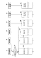
- Inlet temperature of the catalyst is a graph showing the NH 3 conversion characteristics of the catalyst in the case of 280 ° C.. Inlet temperature of the catalyst is a graph showing the NH 3 conversion characteristics of the catalyst in the case of 300 ° C.. It is a sequence diagram of the exhaust gas treatment facility according to the third embodiment. It is a systematic diagram of the exhaust gas treatment facility according to the fourth embodiment. It is a sequence diagram of the exhaust gas treatment facility according to the fourth embodiment. It is a systematic diagram of the exhaust gas treatment facility according to the fifth embodiment.
- the exhaust gas processed by the exhaust gas processing facility of the present embodiment contains CO.
- the exhaust gas treatment facility 1 of the present embodiment includes an oxidation reactor 10 that oxidizes CO contained in the exhaust gas EX, and an exhaust gas EX before flowing into the oxidation reactor 10.
- a heater 20 that controls the amount of heating by the heater 20, and a thermometer 29 that detects the temperature of the exhaust gas EX.
- the reaction vessel of the oxidation reactor 10 is filled with a catalyst 11 that oxidizes CO contained in the exhaust gas EX.
- the oxidation reactor 10 is formed with a pre-oxidation gas inlet 12 through which the pre-treatment gas EXb flows and an oxidized gas outlet 13 through which the treated gas EXa flows out.
- the catalyst 11 filled in the reaction vessel of the oxidation reactor 10 is a catalyst in which Pt is supported on a titania (TiO 2 ) support.
- a catalyst for example, a Pt-based catalyst (Pt / TiO 2 ) in which Pt is supported on a titania support and Sb is not supported, or a Pt—Sb-based catalyst in which Pt and Sb are supported on a titania support ( Pt—Sb / TiO 2 ).
- the Pt-based catalyst is produced, for example, by impregnating anatase-type titanium oxide with a chloroplatinic acid solution and calcining it at about 500 ° C.
- the Pt—Sb-based catalyst is produced by calcining atase type titanium oxide, chloroplatinic acid, water, hydrochloric acid, and antimony chloride at about 500 ° C. All of the above-mentioned methods of making the catalyst are known, and are described in detail, for example, in the above-mentioned Patent Document 1.
- the heat exchanger 15 exchanges heat between the treated gas (or oxidized gas) EXa and the pre-treated gas (or pre-oxidized gas) EXb to cool the treated gas EXa, while heating the pre-treated gas EXb.
- the processed gas EXa and the pre-processing gas EXb may be directly heat-exchanged, but the processed gas EXa and the pre-processing gas EXb may be heat-exchanged via an intermediate medium.
- the heat exchanger 15 includes a pre-treatment gas inlet 16 into which the pre-treatment gas EXb flows, a pre-treatment gas outlet 17 through which the pre-treatment gas EXb flows out, a treated gas inlet 18 into which the treated gas EXa flows in, and a treatment.
- a treated gas outlet 19 through which the gas EXa flows out is formed.
- a pre-treatment gas line 41 is connected to the pre-treatment gas inlet 16 of the heat exchanger 15, and a second pre-treatment gas line 42 is connected to the pre-treatment gas outlet 17 of the heat exchanger 15.
- an exhaust gas EX generation source is connected to the first pre-treatment gas line 41.
- the pre-oxidation gas inlet 12 of the oxidation reactor 10 is connected to the second pre-treatment gas line 42.
- a first treated gas line 43 is connected to the oxidized gas outlet 13 of the oxidation reactor 10.
- the processed gas inlet 18 of the heat exchanger 15 is connected to the first processed gas line 43.
- a second treated gas line 44 is connected to the treated gas outlet 19 of the heat exchanger 15.
- a chimney is connected to the second treated gas line 44.
- the heater 20 has a burner (hereinafter referred to as a burner 20) that injects coke oven gas (hereinafter referred to as COG (Coke Oven Gas)), which is a kind of flammable fluid.
- COG Coke Oven Gas
- the heating amount adjuster 21 controls the valve opening degree of the COG flow rate adjusting valve 23 according to the temperature detected by the thermometer 29 and the COG flow rate adjusting valve 23 that adjusts the flow rate of COG that is a kind of flammable fluid.
- a controller 24 controls the valve opening degree of the COG flow rate adjusting valve 23 according to the temperature detected by the thermometer 29 and the COG flow rate adjusting valve 23 that adjusts the flow rate of COG that is a kind of flammable fluid.
- the burner 20 is provided in the second pre-treatment gas line 42 and injects COG into the line 42.
- the thermometer 29 is provided in the second pre-treatment gas line 42 and closer to the oxidation reactor 10 than the burner 20.
- the controller 24 controls the COG flow control valve 23 so that the temperature detected by the thermometer 29, that is, the temperature of the pre-treatment gas EXb immediately before flowing into the oxidation reactor 10 is within a predetermined temperature range. The valve opening is controlled.
- an oxidation reaction represented by the following formula (1) proceeds by the catalyst 11, and CO becomes CO 2 .
- the CO oxidation rate by the catalyst 11 in other words, the CO combustion rate will be described with reference to FIG. 2 represents the temperature of the exhaust gas EX at the inlet of the oxidation reactor 10 ( ⁇ catalyst inlet temperature), and the vertical axis represents the CO combustion rate.
- the graph shown in FIG. 2 is obtained under the following conditions. Exhaust gas flow rate: 220 [Nl / h-dry] Process gas volume per unit gas contact surface of catalyst (AV): 62.5 [Nm 3 / (m 2 ⁇ hr)] CO: 7000 [ppm-dry] SO 2 : 10 [ppm-dry] O 2 : 13.1 [% -dry] H 2 O: 18 [% -wet]
- the catalyst 11 is a Pt—Sb catalyst (Pt—Sb / TiO 2 ) (the plot is ⁇ ) (the plot is ⁇ ), it is a Pt catalyst (Pt / TiO 2 ) (in the diagram, Even if the plot is ⁇ ), the oxidation reaction is performed when the temperature of the exhaust gas EX at the inlet of the oxidation reactor 10 is 200 or more. Further, a high CO combustion rate can be obtained when the temperature of the exhaust gas EX at the inlet of the oxidation reactor 10 is 240 ° C. or higher.
- the temperature detected by the thermometer 29, that is, the temperature of the pre-treatment gas EXb immediately before flowing into the oxidation reactor 10 is, for example, within a temperature range of 240 ° C. or higher.
- the valve opening degree of the flow rate adjusting valve 23 is controlled by the controller 24.
- the controller 24 opens the COG flow control valve 23.
- the timing at which the COG flow rate adjusting valve 23 opens is before the generation source is operated and the exhaust gas EX from the generation source after operation actually flows into the oxidation reactor 10.
- COG flow control valve 23 is opened, COG is injected from the burner 20 into the second pre-treatment gas line 42, and this COG burns in the second pre-treatment gas line 42.
- the gas temperature in the second pre-treatment gas line 42 is increased by the combustion heat due to the combustion of this COG.
- the temperature of the catalyst 11 before the start of operation of the exhaust gas EX generation source is less than 240 ° C., and is usually room temperature.
- the opening degree of the COG flow control valve 23 is such that the temperature detected by the thermometer 29, that is, the temperature of the pre-treatment gas EXb immediately before flowing into the oxidation reactor 10 is 240 ° C. or more, for example. It adjusts so that it may become (S2: Temperature control process). For this reason, immediately after the start of the operation of the exhaust gas EX generation source, the opening degree of the COG flow rate adjustment valve 23 increases, the COG flow rate injected from the burner 20 increases, and the temperature detected by the thermometer 29 increases. It grows rapidly. In other words, immediately after the start of operation of the exhaust gas EX generation source, the temperature of the catalyst 11 rapidly increases.
- the operation start signal SS indicating the start of operation of the exhaust gas EX generation source for example, the control signal input by the operator to the controller 24 in conjunction with the operation of the exhaust gas EX generation source, the exhaust gas EX generation source is operated.
- a flow rate signal indicating the flow rate of the exhaust gas EX at the source outlet a concentration signal indicating the CO concentration of the exhaust gas EX at the source outlet, and the like.
- a flow rate signal indicating the flow rate of the exhaust gas EX at the generation source outlet is used as the operation start signal SS, if the flow rate indicated by the flow rate signal is equal to or higher than a predetermined value, the generation source is treated as having started operation.
- the pre-treatment gas EXb which is the exhaust gas EX from the generation source, flows into the heat exchanger 15 from the pre-treatment gas inlet 16 of the heat exchanger 15 via the first pre-treatment gas line 41. Further, the gas from the oxidation reactor 10 flows into the heat exchanger 15 from the treated gas inlet 18 of the heat exchanger 15 through the first treated gas line 43. In the heat exchanger 15, the pre-treatment gas EXb and the gas from the oxidation reactor 10 are subjected to heat exchange, and the pre-treatment gas EXb is heated, while the gas from the oxidation reactor 10 is cooled (S3: heat). Exchange process).
- the gas from the oxidation reactor 10 cooled by the heat exchanger 15 is discharged to the atmosphere from a chimney or the like via the second treated gas line 44.
- the pre-treatment gas EXb heated by the heat exchanger 15 flows into the oxidation reactor 10 via the second pre-treatment gas line 42.
- the pre-treatment gas EXb heated by the heat exchanger 15 is further heated by the combustion heat of COG while passing through the second pre-treatment gas line 42. Therefore, the pre-treatment gas EXb is heated by the heat exchanger 15 and the heater 20 and then flows into the oxidation reactor 10.
- the reaction represented by the above-described formula (1) proceeds in the oxidation reactor 10 and the CO in the exhaust gas EX is reduced. It becomes CO 2 (S4: oxidation treatment step).
- the temperature of the treated gas EXa flowing out from the oxidation reactor 10 is higher than the temperature of the pretreatment gas EXb just before flowing into the oxidation reactor 10. .
- the processed gas EXa flows into the heat exchanger 15 from the processed gas inlet 18 of the heat exchanger 15 through the first processed gas line 43.
- the treated gas EXa and the pre-treatment gas EXb are heat-exchanged, and the pre-treatment gas EXb is heated, while the treated gas EXa is cooled (S3: Heat Exchange process).
- the treated gas EXa cooled by the heat exchanger 15 is discharged from the chimney or the like to the atmosphere via the second treated gas line 44.
- the temperature of the treated gas EXa flowing out of the oxidation reactor 10 increases as the reaction proceeds. For this reason, in the heat exchanger 15, when the amount of heat transferred from the treated gas EXa to the pre-treatment gas EXb increases and the amount of gas heating by the combustion heat of the COG is approximately the same, the treatment before being heated by the combustion heat of the COG The temperature of the front gas EXb increases. If the temperature of the pretreatment gas EXb before being heated by the combustion heat of COG increases, the temperature detected by the thermometer 29 also increases.
- the controller 24 gradually decreases the valve opening degree of the COG flow rate adjustment valve 23 according to the temperature increase (S2: temperature adjustment step). That is, the controller 24 controls the valve opening degree of the COG flow rate adjusting valve 23 according to the deviation between the temperature detected by the thermometer 29 and a certain temperature (240 ° C. in this case) within the appropriate temperature range. For this reason, when the temperature detected by the thermometer 29 gradually increases, the heating amount of the pre-treatment gas EXb due to the combustion heat of COG decreases.
- the COG flow control valve 23 is almost closed.
- COG is not substantially injected from the burner 20, and the pre-treatment gas EXb is not heated by the combustion heat of COG. That is, in this case, the temperature of the pre-treatment gas EXb is maintained at, for example, 240 ° C. or higher only with heat generated by the reaction in the oxidation reactor 10.
- the COG flow rate control valve 23 may open. For example, immediately after the flow rate of the exhaust gas EX from the generation source decreases and the calorific value in the oxidation reactor 10 decreases, the flow rate of the exhaust gas EX from the generation source increases, and the heat exchanger 15 Even when the exhaust gas EX is heated, the temperature detected by the thermometer 29 may be lower than 240 ° C. In this case, the COG flow control valve 23 is opened, and the exhaust gas EX before flowing into the oxidation reactor 10 is heated by the combustion heat of COG (S2: temperature adjustment step).
- the heater 20 heats this gas, so that the exhaust gas EX begins to flow into the exhaust gas treatment facility 1. Even in this case, the time lag from the start of inflow to the start of oxidation of CO contained in the exhaust gas EX can be suppressed.
- the gas flowing into the oxidation reactor 10 is heated by the heater 20 before the exhaust gas EX starts to flow into the oxidation reactor 10, so that the exhaust gas immediately after the start of the flow of the exhaust gas EX. CO contained in EX can be oxidized.
- the amount of heating in the heater 20 is controlled according to the temperature detected by the thermometer 29, so that CO can be continuously and stably oxidized. Furthermore, in this embodiment, the amount of heating in the heater 20, in other words, the valve opening degree of the COG flow rate adjusting valve 23 is controlled according to the temperature detected by the thermometer 29, so that it flows into the oxidation reactor 10. If the temperature of the gas to be increased, the flow rate of COG decreases. For this reason, in this embodiment, running cost can be held down.
- the catalyst 11 of the present embodiment is a catalyst in which Pt is supported on a titania (TiO 2 ) support.
- a titania (TiO 2 ) support for example, alumina (Al 2 O 3 )
- SOx sulfur oxide
- Al 2 O 3 alumina
- the exhaust gas treatment facility 1a of the present embodiment is obtained by adding a denitration device 30 to the exhaust gas treatment facility 1 of the first embodiment.
- the denitration apparatus 30 reduces nitrogen oxide (hereinafter referred to as NOx) in the exhaust gas to N 2 and H 2 O or the like.
- NOx nitrogen oxide
- a method for reducing NOx there are an ammonia catalytic reduction method, an ammonia non-catalytic reduction method, a catalytic reduction method and the like. Both the ammonia catalytic reduction method and the ammonia non-catalytic reduction method are methods in which ammonia as a reducing agent is ejected into exhaust gas.
- the catalytic reduction method is a method of reducing NOx with an Ir-containing catalyst or the like without using ammonia.
- the reduction method employed in the present embodiment may be any of the above-described reduction methods, but here, an ammonia catalytic reduction method capable of reducing NOx at a relatively low temperature is employed.
- a denitration apparatus 30 that employs an ammonia catalytic reduction method includes a reactor, a nozzle 32 that ejects ammonia into the reactor, and a catalyst 31 that is filled in the reactor.
- a typical catalyst for example, there is a catalyst in which titania (TiO 2 ) is used as a carrier and V 2 O 5, WO 3, or the like is supported thereon.
- the first pre-treatment gas line 41 is connected to the pre-treatment gas inlet 16 of the heat exchanger 15, and the second pre-treatment gas line is connected to the pre-treatment gas outlet 17 of the heat exchanger 15. 42 is connected.
- the pre-oxidation gas inlet 12 of the oxidation reactor 10 is connected to the second pre-treatment gas line 42.
- An oxidized gas line 45 is connected to the oxidized gas outlet 13 of the oxidation reactor 10.
- the oxidized gas line 45 is connected to a pre-denitration gas inlet 33 of the denitration apparatus 30.
- a first treated gas line 43 is connected to the denitrated gas outlet 34 of the denitration apparatus 30.
- the processed gas inlet 18 of the heat exchanger 15 is connected to the first processed gas line 43 as in the first embodiment.
- a second treated gas line 44 is connected to the treated gas outlet 19 of the heat exchanger 15.
- the burner 20 is provided in the second pre-treatment gas line 42 and injects COG into the line 42.
- the thermometer 29 is provided in the oxidized gas line 45 that connects the oxidation reactor 10 and the denitration apparatus 30.
- the controller 24 of the heating amount controller 21 controls the COG so that the temperature detected by the thermometer 29, that is, the temperature of the oxidized gas EXa1 immediately before flowing into the denitration apparatus 30 falls within a predetermined temperature range.
- the valve opening degree of the flow control valve 23 is controlled.
- the temperature of the exhaust gas flowing into the denitration apparatus 30 and the temperature of the catalyst are preferably 280 ° C. or higher, for example. That is, when the temperature of the exhaust gas flowing into the denitration device 30 and the temperature of the catalyst are 280 ° C. or higher, the NOx reduction rate in the denitration device 30 increases. Furthermore, it is possible to suppress a decrease in catalyst performance due to acidic ammonium sulfate precipitation.
- the COG flow rate is set so that the temperature detected by the thermometer 29, that is, the temperature of the oxidized gas EXa1 immediately before flowing into the denitration apparatus 30 is within a temperature range of, for example, 280 ° C. or higher.
- the valve opening degree of the control valve 23 is controlled by the controller 24. Also in the present embodiment, the controller 24 controls the valve opening degree of the COG flow rate adjusting valve 23 according to the deviation between the temperature detected by the thermometer 29 and a certain temperature (280 ° C. in this case) within the appropriate temperature range. To do.
- the oxidation reactor 10 CO in the exhaust gas is oxidized, and when the reaction temperature is high, SO 2 in the exhaust gas may be oxidized to generate SO 3 .
- This SO 3 is preferably not released into the atmosphere. For this reason, it is preferable that SO 2 is not oxidized in the oxidation reactor 10.
- the denitration device 30 when the denitration device 30 is provided on the downstream side of the oxidation reactor 10 as in the present embodiment, when SO 3 generated in the oxidation reactor 10 flows into the denitration device 30, it is derived from sulfuric acid. Since the catalyst performance deteriorates, it is necessary to increase the NOx reduction reaction temperature in the denitration apparatus 30.
- the denitration apparatus 30 adopts the ammonia reduction method as in the present embodiment
- SO 3 flows into the denitration apparatus 30
- the SO 3 and NH 3 react to form the following formula ( As shown in 4)
- acidic ammonium sulfate is produced.
- This acidic ammonium sulfate corrodes the heat exchanger and the metal material forming each line. Therefore, it is preferable that the catalyst charged in the oxidation reactor 10 can suppress the oxidation of SO 2 in the exhaust gas.
- the horizontal axis represents the contact area of the catalyst per unit gas amount. Therefore, the horizontal axis represents the reciprocal of the amount of processing gas (AV) per unit gas contact surface of the catalyst. In the figure, the vertical axis represents the oxidation rate of SO 2 .
- the contact area (1 / AV) of the catalyst per unit gas amount of the Pt—Sb catalyst (the plot is ⁇ ) Even with this value, the oxidation rate of SO 2 is substantially zero.
- the oxidation rate of SO 2 increases as the contact area (1 / AV) of the catalyst per unit gas amount increases, for example, per unit gas amount
- the contact area of the catalyst is 0.02 [(m 2 ⁇ hr) / Nm 3 ]
- the oxidation rate of SO 2 exceeds 25 [%].
- the Pt—Sb-based catalyst (in the figure, the plot is ⁇ ) is the catalyst contact area per unit gas amount (1 / AV ) Is any value, the oxidation rate of SO 2 is substantially zero.
- the oxidation rate of SO 2 increases as the contact area (1 / AV) of the catalyst per unit gas amount increases, for example, per unit gas amount
- the contact area of the catalyst is 0.02 [(m 2 ⁇ hr) / Nm 3 ]
- the oxidation rate of SO 2 exceeds 25 [%].
- the catalyst charged in the oxidation reactor 10 is preferably a Pt—Sb-based catalyst (Pt—Sb / TiO 2 ). Therefore, in this embodiment, a Pt—Sb-based catalyst (Pt—Sb / TiO 2 ) is used as the catalyst 11 filled in the oxidation reactor 10.
- the COG flow control valve 23 opens and the temperature adjustment step (S2a) is started.
- the timing when the COG flow rate adjusting valve 23 opens is also before the exhaust gas EX from the generated source is actually flown into the oxidation reactor 10 after the generation source is operated, as in the first embodiment.
- the valve opening degree of the COG flow rate adjustment valve 23 is the temperature detected by the thermometer 29, that is, the temperature of the oxidized gas EXa1 just before flowing into the denitration device 30. Is controlled by the controller 24 so as to be, for example, 280 ° C. or higher. Therefore, when this temperature control step (S2a) is started before the generation source is operated and the exhaust gas EX from the operation source after the operation actually flows into the oxidation reactor 10, the denitration device 30 is more influential. The inside of the oxidation reactor 10 arranged on the upstream side is inevitably adjusted to be 280 ° C. or higher.
- the temperature of the exhaust gas flowing into the oxidation reactor 10 is basically The temperature is adjusted to 240 ° C. or higher. That is, in the temperature adjustment step (S2a) of the present embodiment, even when the temperature of the oxidized gas EXa1 immediately before flowing into the denitration device 30 is adjusted to be 280 ° C. or higher, for example, the exhaust gas flowing into the oxidation reactor The temperature is adjusted to 240 ° C. or higher as in the first embodiment.
- the heat exchange step (S3) by the heat exchanger 15 and the oxidation treatment step (S4) by the oxidation reactor 10 are performed. Is executed.
- the exhaust gas treatment facility 1a of the present embodiment has a relationship in which the denitration device 30 is added to the exhaust gas treatment facility 1 of the first embodiment, and thus the denitration step (S5) by the denitration device 30 is executed. . That is, the oxidized gas EXa1 that has flowed out of the oxidation reactor 10 flows into the denitration apparatus 30, and NOx contained in the oxidized gas EXa1 is reduced in the denitration apparatus 30, and this NOx is converted into N 2 and H 2 O or the like (S5: denitration step).
- the exhaust gas EX in which CO in the exhaust gas EX is oxidized and NOx in the exhaust gas EX is reduced is treated as a treated gas (oxidized and denitrated gas) EXa2 as in the first embodiment. It flows into the heat exchanger 15 from the treated gas inlet 18 of the heat exchanger 15 through the spent gas line 43.
- the treated gas EXa2 and the pre-treatment gas (pre-oxidation and pre-denitration gas) EXb are heat-exchanged, and the pre-treatment gas EXb is heated,
- the spent gas EXa2 is cooled (S3: heat exchange step).
- the treated gas EXa2 cooled by the heat exchanger 15 is discharged from the chimney or the like to the atmosphere via the second treated gas line 44.
- the gas flowing into the oxidation reactor 10 and the denitration apparatus 30 when the temperature of the gas flowing into the oxidation reactor 10 and the denitration apparatus 30 is low, the gas is heated by the heater 20, so that the exhaust gas EX is the exhaust gas processing facility 1a. Even when starting to flow in, the time lag from the start of inflow to the start of oxidation of CO contained in the exhaust gas EX can be suppressed. Further, in the present embodiment, when the exhaust gas EX starts to flow into the exhaust gas processing facility 1a, it is possible to suppress a time lag from the start of inflow to the start of reduction of NOx contained in the exhaust gas EX.
- the gas flowing into the oxidation reactor 10 and the denitration device 30 is heated by the heater 20 before the exhaust gas EX begins to flow into the oxidation reactor 10 and the denitration device 30, so the exhaust gas EX Immediately after the start of inflow, CO contained in the exhaust gas EX can be oxidized and NOx can be reduced.
- the heating amount in the heater 20 is controlled according to the temperature detected by the thermometer 29, CO can be continuously oxidized stably and NOx can be continuously increased. Can be stably reduced. Further, in the present embodiment, the amount of heating in the heater 20, in other words, the valve opening degree of the COG flow rate adjusting valve 23 is controlled according to the temperature detected by the thermometer 29, so that the oxidation reactor 10 and the denitration are controlled. If the temperature flowing into the device 30 increases, the flow rate of COG decreases. For this reason, running cost can be held down also in this embodiment.
- thermometer 29 is provided in the oxidized gas line 45 that connects the oxidation reactor 10 and the denitration device 30.
- thermometer 29 may be provided in the second pre-treatment gas line 42 at a position closer to the oxidation reactor 10 than the heater 20.
- the exhaust gas treatment facility 1b of the present embodiment is also obtained by adding a denitration device 30 to the exhaust gas treatment facility 1 of the first embodiment, as in the second embodiment.
- the denitration device 30 is provided on the downstream side of the oxidation reactor, but in this embodiment, the denitration device 30 is provided on the upstream side of the oxidation reactor 10.
- the denitration apparatus 30 of this embodiment is also an apparatus that employs an ammonia catalytic reduction method, like the denitration apparatus 30 of the second embodiment.
- the first pre-treatment gas line 41 is connected to the pre-treatment gas inlet 16 of the heat exchanger 15, and the second pre-treatment gas line is connected to the pre-treatment gas outlet 17 of the heat exchanger 15. 42 is connected.
- the pre-denitration gas inlet 33 of the denitration apparatus 30 is connected to the second pretreatment gas line 42.
- a denitrated gas line 46 is connected to the denitrated gas outlet 34 of the denitration apparatus 30.
- the pre-oxidation gas inlet 12 of the oxidation reactor 10 is connected to the denitrated gas line 46.
- a first treated gas line 43 is connected to the oxidized gas outlet 13 of the oxidation reactor 10.
- the processed gas inlet 18 of the heat exchanger 15 is connected to the first processed gas line 43 as in the first and second embodiments.
- a second treated gas line 44 is connected to the treated gas outlet 19 of the heat exchanger 15.
- the burner 20 is provided in the second pre-treatment gas line 42 as in the first and second embodiments, and injects COG into the line 42.
- the thermometer 29 is provided in the second pre-treatment gas line 42 and closer to the denitration device 30 than the burner 20.
- the controller 24 controls the valve of the COG flow rate adjusting valve 23 so that the temperature detected by the thermometer 29, that is, the temperature of the pre-treatment gas EXb1 immediately before flowing into the denitration apparatus 30 falls within a predetermined temperature range. Opening is controlled.
- the controller 24 of the present embodiment controls the valve opening degree of the COG flow rate adjustment valve 23 so as to be within a temperature range of 280 ° C. or higher.
- ammonia flows out from the denitration apparatus 30 due to catalyst deterioration, partial catalyst blockage, or the like.
- the ammonia is preferably not released into the atmosphere.
- FIGS 9 and 10 show NH 3 conversion characteristics of a Pt-based catalyst (Pt / TiO 2 ) and a Pt—Sb-based catalyst (Pt—Sb / TiO 2 ).
- the horizontal axis represents the contact area of the catalyst per unit gas amount. Therefore, the horizontal axis represents the reciprocal of the amount of processing gas (AV) per unit gas contact surface of the catalyst.
- the vertical axis represents the conversion rate of NH 3 .
- conversion of NH 3 is conversion of NH 3 to N 2 as shown in the following formula (5).
- the contact area (1 / AV) of the catalyst per unit gas amount is 0 for the Pt—Sb catalyst (the plot is ⁇ ). If not [(m 2 ⁇ hr) / Nm 3 ], in other words, if a catalyst is present, NH 3 can be converted to N 2 .
- the Pt-based catalyst (the plot is ⁇ ) also has a catalyst contact area (1 / AV) per unit gas amount of 0 [(m 2 ⁇ hr) / Nm 3 ]. If present, NH 3 can be converted to N 2 .
- NH 3 conversion of Pt-based catalyst is higher than the NH 3 conversion of Pt-Sb-based catalyst. Further, in both the Pt-based catalyst and the Pt—Sb-based catalyst, the NH 3 conversion rate increases as the contact area (1 / AV) of the catalyst per unit gas amount increases.
- the contact area (1 / AV) of the catalyst per unit gas amount is 0 for the Pt—Sb catalyst (the plot is ⁇ ). Unless it is [(m 2 ⁇ hr) / Nm 3 ] or more, NH 3 can be converted to N 2 .
- the Pt-based catalyst (the plot is ⁇ ) also shows that NH 3 is N if the catalyst contact area per unit gas amount (1 / AV) is not 0 [(m 2 ⁇ hr) / Nm 3 ]. Can be converted to 2 .
- both the Pt-based catalyst and the Pt—Sb-based catalyst are the catalyst per unit gas amount, as in the case where the gas temperature at the catalyst inlet is 280 ° C.
- the contact area (1 / AV) increases, the NH 3 conversion increases.
- the gas temperature at the catalyst inlet is 300 ° C.
- the NH 3 conversion rate of the Pt—Sb-based catalyst is higher at 300 ° C. than when the gas temperature at the catalyst inlet is 280 ° C.
- the NH 3 conversion rate of the Pt-based catalyst is almost the same when the gas temperature at the catalyst inlet is 280 ° C. and when it is 300 ° C. Therefore, when the gas temperature at the catalyst inlet of 300 ° C., NH 3 conversion of Pt-Sb-based catalyst, is substantially the same as the NH 3 conversion of Pt based catalyst.
- the catalyst 11 filled in the oxidation reactor 10 may be a Pt—Sb catalyst or a Pt catalyst.
- a Pt-based catalyst is preferable to a Pt—Sb-based catalyst.
- a Pt—Sb-based catalyst is employed as the catalyst 11 to be charged in the oxidation reactor 10 under the condition that the gas temperature at the catalyst inlet is increased. Also good.
- this Pt—Sb-based catalyst can suppress the oxidation of SO 2 . Therefore, whether the Pt—Sb catalyst or the Pt—Sb catalyst is used as the catalyst 11 charged in the oxidation reactor 10 is determined by comparing the NH 3 conversion rate and the SO 2 oxidation rate. Is preferably determined.
- the COG flow control valve 23 opens, The temperature adjustment step (S2b) is started.
- the timing at which the COG flow rate control valve 23 opens is also before the exhaust gas EX from the generated source is actually flown into the oxidation reactor 10 after the generation source is operated. is there.
- the valve opening degree of the COG flow rate adjustment valve 23 is the temperature detected by the thermometer 29, that is, the temperature of the pre-treatment gas EXb1 flowing into the denitration apparatus 30 is, for example,
- the controller 24 controls the temperature to be 280 ° C. or higher.
- the heat exchange step (S3) by the heat exchanger 15, the denitration step (S5b) by the denitration device 30, and the oxidation An oxidation treatment step (S4b) by the reactor 10 is performed.
- the pre-treatment gas (pre-oxidation and pre-denitration gas) EXb1 flows into the denitration apparatus 30, and NOx contained in the pre-treatment gas EXb1 is reduced (S5b: denitration step).
- the temperature of the pretreatment gas EXb1 flowing into the denitration apparatus 30 is adjusted to be 280 ° C. or higher, for example.
- the temperature of the denitrated gas EXb2 from the denitration device 30 flowing into the oxidation reactor 10 is basically adjusted to 240 ° C. or higher.
- Time lag can be suppressed.
- CO can be continuously and stably oxidized, and NOx can be continuously and stably reduced.
- the amount of COG used can be reduced and the running cost can be suppressed.
- the denitration-treated gas EXb2 after the treatment in the denitration step (S5b) is treated in the oxidation treatment step (S4b). That is, in the present embodiment, the oxidation reactor 10 filled with the Pt—Sb catalyst or the Pt catalyst is disposed downstream of the denitration apparatus 30 that employs the ammonia reduction method. Therefore, in the present embodiment, ammonia flowing out from the denitration apparatus 30 can be converted into N 2 by the oxidation reactor 10. For this reason, in this embodiment, the atmospheric release amount of ammonia injected in the denitration apparatus 30 can be suppressed.
- the exhaust gas treatment facility 1c of this embodiment is a modification of the exhaust gas treatment facility 1b of the third embodiment, and the exhaust gas treatment facility 1b includes a first exhaust heat recovery device 35 and a second exhaust heat recovery device 35. An exhaust heat recovery device 49 is added.
- the first exhaust heat recovery unit 35 is a heat exchanger that heats the first refrigerant CM1 while cooling the processed gas EXa2 by exchanging heat between the processed gas EXa2 and the first refrigerant CM1.
- the first exhaust heat recovery unit 35 is provided in the first treated gas line 43.
- the exhaust gas treatment facility 1c of this embodiment further includes a heat exchange limiter 36 that restricts heat exchange between the processed gas EXa2 and the first refrigerant CM1 in the first exhaust heat recovery device 35.
- This heat exchange limiter 36 is oxidized in the refrigerant flow rate adjustment valve 37 that adjusts the flow rate of the first refrigerant CM1 that passes through the refrigerant line connected to the first exhaust heat recovery unit 35, and in the first treated gas line 43.
- a thermometer 39 provided between the reactor 10 and the first exhaust heat recovery unit 35 and a controller 38 are provided. The opening degree of the refrigerant flow control valve 37 is controlled by the controller 38 according to the temperature detected by the thermometer 39.
- the second exhaust heat recovery device 49 is a heat exchanger that heats the second refrigerant CM2 while cooling the processed gas EXa2 by exchanging heat between the processed gas EXa2 and the second refrigerant CM2.
- the second exhaust heat recovery device 49 is provided in the second processed gas line 44.
- the temperature adjustment step (S2b) by the heating amount controller 21, the heat exchange step (S3) by the heat exchanger 15, the denitration step (S5b) by the denitration device 30, and the oxidation reaction An oxidation treatment step (S4b) by the vessel 10 is performed.
- the 1st waste heat recovery process (S6) by the 1st waste heat recovery device 35 and the 2nd waste heat recovery process (S7) by the 2nd waste heat recovery device 49 are also performed.
- the COG flow rate control valve 23 is completely closed and is processed by the heater 20.
- the front gas EXb1 is not heated.
- the amount of heat generated in the oxidation reactor 10 increases.
- the temperature of the exhaust gas flowing into the oxidation reactor 10 and the denitration device 30 also increases.
- the catalyst with which the oxidation reactor 10 is filled, and the catalyst with which the denitration apparatus 30 is filled the gas processing capacity increases as the temperature increases. However, if the temperature of the catalyst becomes too high, the gas processing capacity is lowered and the deterioration of the catalyst is accelerated.
- the controller 38 opens the refrigerant flow rate adjustment valve 37, and One exhaust heat recovery device 35 exchanges heat between the processed gas EXa2 and the first refrigerant CM1 (S6: first exhaust heat recovery step).
- S6 first exhaust heat recovery step
- the processed gas EXa2 is cooled, while the first refrigerant CM1 is heated.
- the heat of the heated first refrigerant CM1 is used as appropriate.
- thermometer 39 if the temperature detected by the thermometer 39 is lower than a predetermined temperature (for example, 350 ° C.), the refrigerant flow rate adjustment valve 37 is closed, and the gas that has been processed by the first exhaust heat recovery device 35 is closed. Heat exchange between EXa2 and the first refrigerant CM1 is not performed.
- a predetermined temperature for example, 350 ° C.
- the temperature of the pre-treatment gas EXb1 immediately before flowing into the denitration apparatus 30 is 280 ° C.
- the temperature of the treated gas EXa2 after being cooled by the heat exchanger 15 is around 200 ° C. Therefore, in the present embodiment, the heat of the processed gas EXa2 is recovered by the second exhaust heat recovery device 49 to make effective use of this heat.
- thermometer 39 for opening and closing the refrigerant flow rate adjusting valve 37 is provided separately, and the temperature detected by the thermometer 39 is detected. In response to this, the opening and closing of the refrigerant flow control valve 37 is controlled. However, the opening / closing of the refrigerant flow rate adjustment valve 37 may be controlled according to the temperature detected by the thermometer 29 for opening / closing the COG flow rate adjustment valve 23.
- the heat exchange between the processed gas EXa2 and the first refrigerant CM1 is limited by opening and closing the refrigerant flow rate adjustment valve 37 provided in the refrigerant line.
- a bypass line that bypasses the first exhaust heat recovery device 35 is provided in the first treated gas line 43, and a bypass flow rate adjustment valve is provided in the bypass line, and the treated gas EXa2 is opened and closed by opening and closing the bypass flow rate adjustment valve.
- heat exchange between the first refrigerant CM1 and the first refrigerant CM1 may be limited.
- the bypass flow rate adjustment valve is opened and the processed gas EXa2 and the first refrigerant CM1 by the first exhaust heat recovery device 35 are opened. Limit heat exchange with.
- the exhaust gas treatment facility 1b of the third embodiment is provided with a first exhaust heat recovery device 35, a second exhaust heat recovery device 49, and the like.
- first exhaust heat recovery unit 35 and the second exhaust heat recovery unit 49 may be provided.
- the first exhaust heat recovery device in this embodiment is added to the exhaust gas treatment facility 1 of the first embodiment or the exhaust gas treatment facility 1a of the second embodiment.
- One or both of 35 and the second exhaust heat recovery unit 49 may be added.
- Each of the heaters 20 in each of the above embodiments injects COG and heats the gas with the combustion heat of this COG.
- the heater may inject a combustible fluid other than COG and heat the gas with the combustion heat of the combustible fluid.
- the gas may be heated by heat generated by an electric heater without using a flammable fluid.
- the thermometer may be in any form as long as it can detect the temperature, and may be a thermocouple, a thin film temperature sensor, a laser temperature measuring instrument, or the like.
- Many steel mills have a sintering furnace 51 that mixes lime with iron ore as a raw material to produce sintered ore 57 that is an agglomeration of ore, and a coke furnace 52 that steams and burns coal to produce coke 58. And a blast furnace 53 in which the coke 58 is put into the sintered ore 57 and iron content in the sintered ore 57 is taken out, and an exhaust gas processing facility for processing the exhaust gas EX from the sintering furnace 51 is provided.
- the exhaust gas treatment facility 1d of the present embodiment is an exhaust gas treatment facility in this steelworks.
- the exhaust gas treatment facility 1d includes an exhaust gas treatment facility 1c according to the fourth embodiment, an exhaust gas line 56 through which the exhaust gas EX from the sintering furnace 51 flows, and the exhaust gas treatment facility 1c.
- the exhaust gas line 56 is connected to the first pretreatment gas line 41 in the exhaust gas treatment facility 1c.
- the dust collector 54 may be either a wet type dust collector or a dry type dust collector. Further, as the dust collector 54, both a wet type dust collector and a dry type dust collector may be provided.
- the desulfurization device 55 is a device that, for example, wet-treats the exhaust gas EX using limestone as an absorbent and takes out SOx reacted with the limestone as gypsum.
- the COG generated in the coke oven 52 is supplied to the burner 20 of the exhaust gas treatment facility 1d of the present embodiment.
- the exhaust gas treatment facility 1d of this embodiment is obtained by adding a dust collector 54, a desulfurization device 55, and the like to the exhaust gas treatment facility 1c in the fourth embodiment.
- a dust collector 54, a desulfurization device 55, etc. are added to the exhaust gas treatment facilities 1, 1a, 1b in the first to third embodiments, and the configuration is the same as that of the exhaust gas treatment facility 1d of the present embodiment. Good.
- the exhaust gas treatment facility 1d of the present embodiment is for treating the exhaust gas EX from the sintering furnace 51 of the steel mill.
- the exhaust gas processing facility in each of the above embodiments may process the exhaust gas EX from a gas generation source other than the sintering furnace 51.
Abstract
This exhaust gas treatment system (1) is provided with an oxidation reactor (10), a heat exchanger (15), a heater (20), a thermometer (29) and a heating amount controller (21). The oxidation reactor (10) is internally filled with a catalyst (11) wherein Pt is supported by a titania carrier, and oxidizes carbon monoxide contained in an exhaust gas (EX). The heat exchanger (15) heats the gas before oxidation (EXb), which is the gas before being treated by the oxidation reactor (10), by performing heat exchange between the gas before oxidation (EXb) and the oxidized gas (EXa), which is the gas after being treated by the oxidation reactor (10). The heater (20) heats the gas before oxidation (EXb) after passing through the heat exchanger (15). The heating amount controller (21) controls the amount of heating by the heater (20) so that the temperature detected by the thermometer (29) is within a predetermined temperature range.
Description
本発明は、排気ガス中の一酸化炭素を酸化処理する排気ガス処理設備、及び排気ガス処理方法に関する。
The present invention relates to an exhaust gas processing facility for oxidizing carbon monoxide in exhaust gas and an exhaust gas processing method.
排気ガス中の一酸化炭素(以下、COとする)を酸化処理する場合、一般的に、所定の温度範囲内の排気ガスを触媒に接触させ、この排気ガス中のCOを触媒燃焼させることが多い。
When oxidizing carbon monoxide (hereinafter referred to as CO) in exhaust gas, generally, exhaust gas within a predetermined temperature range is brought into contact with a catalyst, and CO in the exhaust gas is catalytically combusted. Many.
この触媒としては、例えば、以下の特許文献1に記載されているように、チタニア担体にPtを担持させた触媒が知られている。
As this catalyst, for example, as described in Patent Document 1 below, a catalyst in which Pt is supported on a titania carrier is known.
一酸化炭素の酸化処理では、排気ガスが処理装置に流入し始めると、この処理装置で直ちに一酸化炭素が酸化処理され、その後も安定して一酸化炭素が酸化処理されることが望まれる。さらに、一酸化炭素の酸化処理では、ランニングコストを抑えることが望まれる。
In the oxidation treatment of carbon monoxide, it is desired that when the exhaust gas starts to flow into the treatment apparatus, the carbon monoxide is immediately oxidized by this treatment apparatus, and thereafter the carbon monoxide is stably oxidized. Furthermore, it is desired to reduce running costs in the oxidation treatment of carbon monoxide.
そこで、本発明は、ランニングコストを抑えつつも、プラント起動時などのコールドスタート時等における排気ガスの流入開始からの一酸化炭素の酸化処理開始までのタイムラグを抑え、その後も安定して一酸化炭素を酸化させることができる技術を提供することを目的とする。
Therefore, the present invention suppresses the running cost, suppresses the time lag from the start of the exhaust gas inflow to the start of the oxidation treatment of carbon monoxide at the time of cold start such as at the time of starting the plant, and then stably stabilizes the monoxide. It aims at providing the technique which can oxidize carbon.
上記目的を達成するための一態様としての排気ガス処理設備は、
チタニア担体にPt及びSbが担持されているPt-Sb系触媒、又はチタニア担体にPtが担持されSbが担持されていないPt系触媒が充填され、排気ガス中に含まれている一酸化炭素を酸化させる酸化反応器と、前記酸化反応器で処理される前の排気ガスである酸化前ガスと前記酸化反応器で処理された後の排気ガスである酸化済みガスとを熱交換させて、前記酸化済みガスを冷却する一方で、前記酸化前ガスを加熱する熱交換器と、前記熱交換器を通った後の前記酸化前ガスを加熱する加熱器と、前記加熱器により加熱されたガスの温度を検知する温度計と、前記温度計で検知される温度が予め定められた温度範囲内に収まるよう、前記加熱器による加熱量を調節する加熱量調節器と、を備える。 An exhaust gas treatment facility as one aspect for achieving the above object is:
The Pt-Sb catalyst in which Pt and Sb are supported on the titania support, or the Pt catalyst in which Pt is supported but not Sb on the titania support, and carbon monoxide contained in the exhaust gas is filled. Heat exchange between an oxidation reactor to be oxidized, a pre-oxidation gas that is an exhaust gas before being processed in the oxidation reactor, and an oxidized gas that is an exhaust gas after being processed in the oxidation reactor; While cooling the oxidized gas, a heat exchanger for heating the pre-oxidation gas, a heater for heating the pre-oxidation gas after passing through the heat exchanger, and a gas heated by the heater A thermometer that detects the temperature, and a heating amount adjuster that adjusts a heating amount by the heater so that the temperature detected by the thermometer falls within a predetermined temperature range.
この排気ガス処理設備の触媒は、チタニア担体にPtが担持されている触媒である。このため、この排気ガス処理設備では、排気ガス中に硫黄酸化物(以下、SOxとする)が含まれている場合でも、例えば、アルミナ担体にPtが担持されている触媒よりも、触媒の性能劣化を抑えることができる。
The catalyst of this exhaust gas treatment facility is a catalyst in which Pt is supported on a titania carrier. Therefore, in this exhaust gas treatment facility, even when sulfur oxide (hereinafter referred to as SOx) is contained in the exhaust gas, for example, the performance of the catalyst is better than that of a catalyst in which Pt is supported on an alumina carrier. Deterioration can be suppressed.
また、この排気ガス処理設備では、酸化反応器に流入するガスの温度が低い場合には、加熱器でこのガスを加熱するので、排気ガスが排気ガス処理設備に流入し始めたときでも、流入開始からこの排気ガス中に含まれるCOの酸化が開始されるまでのタイムラグを抑えることができる。さらに、この排気ガス処理設備では、温度計で検知される温度に応じて、加熱器での加熱量を制御するので、COを継続的に安定して酸化させることができる。さらに、この排気ガス処理設備では、温度計で検知される温度に応じて、加熱器での加熱量が調節されるので、酸化反応器に流入するガスの温度が高くなれば、加熱器による加熱量が減る。このため、この排気ガス処理設備では、ランニングコストを抑えることができる。
Also, in this exhaust gas treatment facility, when the temperature of the gas flowing into the oxidation reactor is low, this gas is heated by a heater, so even when the exhaust gas starts to flow into the exhaust gas treatment facility, A time lag from the start to the start of oxidation of CO contained in the exhaust gas can be suppressed. Furthermore, in this exhaust gas treatment facility, the amount of heating in the heater is controlled according to the temperature detected by the thermometer, so that CO can be oxidized continuously and stably. Furthermore, in this exhaust gas treatment facility, the amount of heating in the heater is adjusted according to the temperature detected by the thermometer, so if the temperature of the gas flowing into the oxidation reactor increases, the heating by the heater The amount is reduced. For this reason, in this exhaust gas treatment facility, the running cost can be suppressed.
ここで、前記排気ガス処理設備において、前記加熱量調節器は、稼動し始めたガス発生源からの前記排気ガスが前記酸化反応器に流入する前から、前記温度計で検知される温度が前記予め定められた温度範囲内に収まるよう、前記加熱器による加熱量を調節してもよい。
Here, in the exhaust gas treatment facility, the heating amount controller is configured such that the temperature detected by the thermometer before the exhaust gas from the gas generation source that has started operating flows into the oxidation reactor. The amount of heating by the heater may be adjusted so that it falls within a predetermined temperature range.
この排気ガス処理設備では、稼動し始めたガス発生源からの排気ガスが酸化反応器に流入する前から、加熱器による加熱量が調節されるので、稼動し始めたガス発生源からの排気ガスが酸化反応器に流入し始めた直後から、この排気ガス中に含まれるCOを酸化することができる。
In this exhaust gas treatment facility, since the amount of heating by the heater is adjusted before the exhaust gas from the gas generation source that has started operating flows into the oxidation reactor, the exhaust gas from the gas generation source that has started operating Immediately after starting to flow into the oxidation reactor, CO contained in the exhaust gas can be oxidized.
また、以上のいずれかの前記排気ガス処理設備において、前記加熱器により加熱された後であって前記熱交換器で冷却される前の前記排気ガス中に含まれている窒素酸化物を還元させる脱硝装置を備えてもよい。
また、以上のいずれかの前記排気ガス処理装置において、前記熱交換器と前記酸化反応器とを接続し、前記熱交換器から前記酸化反応器へ前記酸化前ガスを送る第一ラインと、前記酸化反応器と前記熱交換器とを接続し、前記酸化反応器から前記熱交換器へ前記酸化済みガスを送る第二ラインと、を備え、前記脱硝装置は、前記第一ライン中又は前記第二ライン中に設けられていてもよい。 Further, in any one of the above exhaust gas treatment facilities, nitrogen oxides contained in the exhaust gas after being heated by the heater and before being cooled by the heat exchanger are reduced. A denitration device may be provided.
Further, in any one of the above exhaust gas treatment devices, the heat exchanger and the oxidation reactor are connected, and a first line for sending the pre-oxidation gas from the heat exchanger to the oxidation reactor, A second line that connects the oxidation reactor and the heat exchanger and sends the oxidized gas from the oxidation reactor to the heat exchanger, and the denitration device is in the first line or the second line It may be provided in two lines.
この排気ガス処理設備では、排気ガス中の窒素酸化物を除くことができる。
In this exhaust gas treatment facility, nitrogen oxides in the exhaust gas can be removed.
前記脱硝装置を備える前記排気ガス処理設備において、前記脱硝装置は、前記酸化反応器で処理された後であって前記熱交換器で冷却される前の前記酸化済みガスを処理し、前記温度計は、前記酸化反応器を通った後であって前記脱硝装置に流入する前のガスの温度を検知してもよい。
また、前記第一ライン及び前記第二ラインを備えている前記排気ガス処理設備において、前記脱硝装置は、前記第二ライン中に設けられ、前記温度計は、前記第二ライン中であって、前記脱硝装置よりも前記酸化反応器側の位置に設けられていてもよい。 In the exhaust gas treatment facility including the denitration device, the denitration device treats the oxidized gas after being treated by the oxidation reactor and before being cooled by the heat exchanger, and the thermometer May detect the temperature of the gas after passing through the oxidation reactor and before flowing into the denitration apparatus.
Further, in the exhaust gas treatment facility comprising the first line and the second line, the denitration device is provided in the second line, and the thermometer is in the second line, It may be provided at a position closer to the oxidation reactor than the denitration device.
この排気ガス処理装置では、酸化反応器から流出したガスの温度を検知することで、酸化反応器でCOを酸化反応させるための温度を管理することができる上に、脱硝装置で脱硝反応させるための温度も管理することができる。
In this exhaust gas treatment device, by detecting the temperature of the gas flowing out from the oxidation reactor, the temperature for oxidizing the CO in the oxidation reactor can be controlled, and in addition, the denitration device can perform the denitration reaction. The temperature of the can also be managed.
前記脱硝装置を備える、以上のいずれかの前記排気ガス処理設備において、前記酸化反応器には、前記Pt-Sb系触媒が充填されていてもよい。
In any one of the above exhaust gas treatment facilities provided with the denitration apparatus, the oxidation reactor may be filled with the Pt—Sb-based catalyst.
チタニア担体にPt及びSbが担持されているPt-Sb系触媒は、チタニア担体にPtが担持されSbが担持されていないPt系触媒よりも、SO2の酸化率が低い。このため、この排気ガス処理設備では、SO2の酸化を抑制することができる。
A Pt—Sb-based catalyst in which Pt and Sb are supported on a titania support has a lower SO 2 oxidation rate than a Pt-based catalyst in which Pt is supported on a titania support and Sb is not supported. For this reason, in this exhaust gas treatment facility, oxidation of SO 2 can be suppressed.
前記脱硝装置を備える前記排気ガス処理設備において、前記脱硝装置は、前記排気ガス中に窒素酸化物の還元剤としてアンモニアを噴出するアンモニア脱硝装置であり、前記アンモニア脱硝装置は、前記加熱器により加熱された後であって前記酸化反応器で処理される前の前記酸化前ガスを処理してもよい。
また、前記第一ライン及び前記第二ラインを備えている前記排気ガス処理設備において、前記脱硝装置は、前記排気ガス中に窒素酸化物の還元剤としてアンモニアを噴出するアンモニア脱硝装置であり、前記アンモニア脱硝装置は、前記第一ライン中であって、前記加熱器よりも前記酸化反応器側の位置に設けられていてもよい。 In the exhaust gas treatment facility including the denitration apparatus, the denitration apparatus is an ammonia denitration apparatus that ejects ammonia as a nitrogen oxide reducing agent into the exhaust gas, and the ammonia denitration apparatus is heated by the heater. The pre-oxidation gas after being processed and before being processed in the oxidation reactor may be processed.
Further, in the exhaust gas treatment facility including the first line and the second line, the denitration apparatus is an ammonia denitration apparatus that ejects ammonia as a nitrogen oxide reducing agent in the exhaust gas, The ammonia denitration apparatus may be provided in the first line and at a position closer to the oxidation reactor than the heater.
アンモニア脱硝装置では、一般的に、この脱硝装置からアンモニアが流出する。このアンモニアは、大気に放出しないことが好ましい。この排気ガス処理設備は、排気ガスが脱硝装置を通った後、酸化反応器に流入する。このため、この排気ガス処理設備では、酸化反応器で、脱硝装置から流出したアンモニアを窒素に転換することができる。この結果、アンモニアと硫黄酸化物との反応による酸性硫安が生成されず、この酸性硫安によって、脱硝装置の後段に設けられている機器や配管の腐食を抑制することができる。さらに、アンモニアの大気放出を抑制することができる。
In an ammonia denitration apparatus, ammonia generally flows out from this denitration apparatus. The ammonia is preferably not released into the atmosphere. In this exhaust gas treatment facility, after the exhaust gas passes through the denitration device, it flows into the oxidation reactor. For this reason, in this exhaust gas treatment facility, the ammonia flowing out from the denitration apparatus can be converted into nitrogen by the oxidation reactor. As a result, acidic ammonium sulfate due to the reaction between ammonia and sulfur oxide is not generated, and corrosion of equipment and piping provided downstream of the denitration device can be suppressed by this acidic ammonium sulfate. Furthermore, the release of ammonia into the atmosphere can be suppressed.
前記酸化反応器で処理される前の前記酸化前ガスを処理するアンモニア脱硝装置を備える前記排気ガス処理設備において、前記温度計は、前記加熱器により加熱された後であって前記アンモニア脱硝装置に流入する前のガスの温度を検知してもよい。
In the exhaust gas treatment facility provided with an ammonia denitration device for treating the pre-oxidation gas before being treated in the oxidation reactor, the thermometer is heated by the heater and is supplied to the ammonia denitration device. You may detect the temperature of the gas before flowing in.
この排気ガス処理設備では、アンモニア脱硝装置に流入する前の温度を検知し、この温度を適切な温度に制御することにより、脱硝装置及び酸化反応器を効率的に運用することができる。
In this exhaust gas treatment facility, the temperature before flowing into the ammonia denitration device is detected, and by controlling this temperature to an appropriate temperature, the denitration device and the oxidation reactor can be operated efficiently.
他の態様としての排気ガス処理設備は、
排気ガス中に窒素酸化物の還元剤としてアンモニアを噴出し、前記窒素酸化物を還元させる脱硝装置と、前記脱硝装置で処理された排気ガス中に含まれている一酸化炭素を酸化させる酸化反応器と、を備え、前記酸化反応器には、チタニア担体にPt及びSbが担持されているPt-Sb系触媒、又はチタニア担体にPtが担持されSbが担持されていないPt系触媒が充填されている。 The exhaust gas treatment facility as another aspect is
A denitration device that ejects ammonia as a nitrogen oxide reducing agent into exhaust gas to reduce the nitrogen oxide, and an oxidation reaction that oxidizes carbon monoxide contained in the exhaust gas treated by the denitration device The oxidation reactor is filled with a Pt—Sb catalyst in which Pt and Sb are supported on a titania support, or a Pt catalyst in which Pt is supported on a titania support and not Sb. ing.
この排気ガス処理設備では、排気ガス中に含まれている窒素酸化物を還元することができると共に、排気ガス中に含まれている一酸化炭素を酸化させることができる。さらに、この排気ガス処理設備では、酸化反応器で、脱硝装置から流出したアンモニアを窒素に転換することができる。この結果、アンモニアと硫黄酸化物との反応による酸性硫安が生成されず、この酸性硫安によって、脱硝装置の後段に設けられている機器や配管の腐食を抑制することができる。さらに、アンモニアの大気放出を抑制することができる。
This exhaust gas treatment facility can reduce nitrogen oxides contained in the exhaust gas and oxidize carbon monoxide contained in the exhaust gas. Further, in this exhaust gas treatment facility, the ammonia flowing out from the denitration device can be converted into nitrogen by the oxidation reactor. As a result, acidic ammonium sulfate due to the reaction between ammonia and sulfur oxide is not generated, and corrosion of equipment and piping provided downstream of the denitration device can be suppressed by this acidic ammonium sulfate. Furthermore, the release of ammonia into the atmosphere can be suppressed.
前記他の態様としての前記排気ガス処理設備において、前記脱硝装置及び前記酸化反応器で処理される前の前記排気ガスである処理前ガスと前記脱硝装置及び前記酸化反応器で処理された後の前記排気ガスである処理済みガスとを熱交換させ、前記処理済みガスを冷却する一方で、前記処理前ガスを加熱する熱交換器と、前記熱交換器を通った後の前記処理前ガスを加熱する加熱器と、前記加熱器による加熱量を調節する加熱量調節器と、を備えてもよい。
In the exhaust gas treatment facility as the other aspect, the pre-treatment gas which is the exhaust gas before being treated by the denitration apparatus and the oxidation reactor, and after being treated by the denitration apparatus and the oxidation reactor Heat exchange with the treated gas, which is the exhaust gas, cools the treated gas, while heating the pre-treated gas, and the pre-treated gas after passing through the heat exchanger You may provide the heater to heat and the heating amount regulator which adjusts the heating amount by the said heater.
前記酸化反応器及び前記脱硝装置を備える、以上のいずれかの前記排気ガス処理設備において、前記酸化反応器及び前記脱硝装置で処理された後であって前記熱交換器で冷却される前の前記排気ガスと第一冷媒とを熱交換させ、前記排気ガスを冷却する一方で、前記第一冷媒を加熱する排熱回収器を備えてもよい。
In any one of the exhaust gas treatment facilities including the oxidation reactor and the denitration device, the exhaust gas treatment facility after being treated by the oxidation reactor and the denitration device and before being cooled by the heat exchanger. An exhaust heat recovery device may be provided that heats the first refrigerant while allowing the exhaust gas and the first refrigerant to exchange heat and cooling the exhaust gas.
この排気ガス処理設備では、酸化反応器で発生する熱のうちで不要な熱を回収し、これを有効利用することができる。
In this exhaust gas treatment facility, unnecessary heat can be recovered from the heat generated in the oxidation reactor and used effectively.
前記排熱回収器を備える前記排気ガス処理設備において、前記排熱回収器で熱交換される前の前記排気ガスの温度が予め定められている温度よりも低い場合に、前記排熱回収器での前記排気ガスと前記第一冷媒との熱交換を制限する熱交換制限器を備えてもよい。
In the exhaust gas treatment facility including the exhaust heat recovery device, when the temperature of the exhaust gas before heat exchange in the exhaust heat recovery device is lower than a predetermined temperature, the exhaust heat recovery device There may be provided a heat exchange limiter for restricting heat exchange between the exhaust gas and the first refrigerant.
酸化反応器に充填されている触媒は、その温度が高くなりすぎると、SO2の酸化速度が上昇し、大量のSO3が生成される。このため、このSO3の生成により、酸化反応器の後段に設けられている機器や配管の腐食や、煙突からの紫煙が発生することがある。この排気ガス処理設備では、排気ガスの温度が予め定められている温度よりも低い場合に、排熱回収器での排気ガスと冷媒との熱交換を制限され、排気ガスの温度が予め定められている温度以上の場合に、排熱回収器での排気ガスと冷媒との熱交換が行われる。よって、この排気ガス処理設備では、排熱回収器での熱交換により、触媒の必要以上の温度上昇を抑えることができ、SO3の生成を抑制することができる。
If the temperature of the catalyst charged in the oxidation reactor becomes too high, the oxidation rate of SO 2 increases and a large amount of SO 3 is generated. For this reason, the generation of SO 3 may cause corrosion of equipment and piping provided in the subsequent stage of the oxidation reactor and purple smoke from the chimney. In this exhaust gas treatment facility, when the temperature of the exhaust gas is lower than a predetermined temperature, heat exchange between the exhaust gas and the refrigerant in the exhaust heat recovery device is limited, and the temperature of the exhaust gas is determined in advance. When the temperature is equal to or higher than the temperature, heat exchange between the exhaust gas and the refrigerant in the exhaust heat recovery unit is performed. Therefore, in this exhaust gas treatment facility, the temperature increase of the catalyst more than necessary can be suppressed by heat exchange in the exhaust heat recovery device, and the generation of SO 3 can be suppressed.
以上のいずれかの前記排気ガス処理設備において、前記熱交換器で冷却された後の前記排気ガスと第二冷媒とを熱交換させ、前記排気ガスを冷却する一方で、前記第二冷媒を加熱する排熱回収器を備えてもよい。
In any one of the above exhaust gas treatment facilities, the exhaust gas after being cooled by the heat exchanger and the second refrigerant are heat-exchanged to cool the exhaust gas while heating the second refrigerant. An exhaust heat recovery device may be provided.
この排気ガス処理設備では、熱交換器で冷却された後の排気ガスの熱を回収し、これを有効利用することができる。
In this exhaust gas treatment facility, the heat of the exhaust gas after being cooled by the heat exchanger can be recovered and used effectively.
以上のいずれかの前記排気ガス処理設備において、前記酸化反応器で処理される前の前記排気ガス中から塵を除く集塵器を備えてもよい。
Any of the above exhaust gas treatment facilities may include a dust collector that removes dust from the exhaust gas before being treated in the oxidation reactor.
上記目的を達成するための一態様としての排気ガス処理方法は、
酸化反応器内で、チタニア担体にPt及びSbが担持されているPt-Sb系触媒、又はチタニア担体にPtが担持されSbが担持されていないPt系触媒により、排気ガス中に含まれている一酸化炭素を酸化させる酸化処理工程と、前記酸化処理工程で処理される前の排気ガスである酸化前ガスと前記酸化処理工程で処理された後の排気ガスである酸化済みガスとを熱交換器で熱交換させて、前記酸化済みガスを冷却する一方で、前記酸化前ガスを加熱する熱交換工程と、前記熱交換器を通った前記酸化前ガスを加熱し、加熱後の前記排気ガスの温度が予め定められた温度範囲内に収まるよう、前記排気ガスの温度を調節する温度調節工程と、を含む。 An exhaust gas treatment method as one aspect for achieving the above object is as follows:
In the oxidation reactor, it is contained in the exhaust gas by a Pt—Sb-based catalyst in which Pt and Sb are supported on a titania support, or a Pt-based catalyst in which Pt is supported on a titania support but not Sb. Heat exchange between an oxidation treatment step for oxidizing carbon monoxide and a pre-oxidation gas that is an exhaust gas before being treated in the oxidation treatment step and an oxidized gas that is an exhaust gas after being treated in the oxidation treatment step A heat exchange step of heating the pre-oxidation gas while cooling the oxidized gas by a heat exchanger, and heating the pre-oxidation gas that has passed through the heat exchanger and heating the exhaust gas Adjusting the temperature of the exhaust gas such that the temperature of the exhaust gas falls within a predetermined temperature range.
この排気ガス処理方法では、排気ガス中にSOxが含まれている場合でも、例えば、アルミナ担体にPtが担持されている触媒よりも、触媒の性能劣化を抑えることができる。
In this exhaust gas treatment method, even when SOx is contained in the exhaust gas, for example, the catalyst performance deterioration can be suppressed more than that of a catalyst in which Pt is supported on an alumina carrier.
また、この排気ガス処理方法では、熱交換器を通った酸化前ガスの温度が低い場合には、このガスが加熱されるので、排気ガスが排気ガス処理設備に流入し始めたときでも、流入開始からこの排気ガス中に含まれるCOの酸化が開始されるまでのタイムラグを抑えることができる。さらに、この排気ガス処理方法では、温度調節工程で、予め定められた温度範囲内に収まるよう、排気ガスの温度が調節されるので、COを継続的に安定して酸化させることができる。さらに、この排気ガス処理設備では、この温度調節工程での余分な加熱を抑えることができ、ランニングコストを抑えることができる。
Also, in this exhaust gas treatment method, when the temperature of the pre-oxidation gas that has passed through the heat exchanger is low, this gas is heated, so even if the exhaust gas begins to flow into the exhaust gas treatment facility, A time lag from the start to the start of oxidation of CO contained in the exhaust gas can be suppressed. Furthermore, in this exhaust gas treatment method, the temperature of the exhaust gas is adjusted in the temperature adjustment step so as to be within a predetermined temperature range, so that CO can be oxidized stably and continuously. Furthermore, with this exhaust gas treatment facility, it is possible to suppress excessive heating in this temperature adjustment step, and it is possible to reduce running costs.
ここで、前記排気ガス処理方法において、前記温度調節工程では、稼動し始めたガス発生源からの前記排気ガスが前記酸化反応器に流入する前から、前記酸化反応器に流入する前又は前記酸化反応器から流出したガスの温度が前記予め定められた温度範囲内に収まるよう、前記ガスの温度を調節してもよい。
Here, in the exhaust gas processing method, in the temperature adjusting step, before the exhaust gas from the gas generation source that has started to operate flows into the oxidation reactor, before flowing into the oxidation reactor or before the oxidation The temperature of the gas may be adjusted so that the temperature of the gas flowing out from the reactor falls within the predetermined temperature range.
以上のいずれかの前記排気ガス処理方法において、前記温度調節工程で温度調整された後であって前記熱交換工程で冷却される前の前記排気ガス中に含まれている窒素酸化物を脱硝装置で還元させる脱硝工程を含み、前記脱硝工程では、前記酸化処理工程で処理された後であって前記熱交換工程で冷却される前の前記酸化済みガスを処理し、前記温度調節工程では、前記酸化反応器から流出し前記脱硝装置に流入する前のガスが前記予め定められた温度範囲内に収まるよう、前記ガスの温度を調節してもよい。
In any one of the exhaust gas treatment methods described above, the NOx removal apparatus removes nitrogen oxides contained in the exhaust gas after temperature adjustment in the temperature adjustment step and before cooling in the heat exchange step In the denitration step, the oxidized gas after being treated in the oxidation treatment step and before being cooled in the heat exchange step is treated, and in the temperature adjustment step, The temperature of the gas may be adjusted so that the gas before flowing out of the oxidation reactor and before flowing into the denitration apparatus falls within the predetermined temperature range.
これにより、従来、脱硝工程の温度を適切な温度に維持するために、加熱用の燃料等を大量に使用していたが、その燃料等の使用量を抑制することができる。
Thereby, conventionally, in order to maintain the temperature of the denitration process at an appropriate temperature, a large amount of fuel for heating or the like has been used, but the amount of fuel or the like used can be suppressed.
以上のいずれかの前記排気ガス処理方法において、前記温度調節工程で温度調整された後であって前記熱交換工程で冷却される前の前記排気ガス中に含まれている窒素酸化物を脱硝装置で還元させる脱硝工程を含み、前記脱硝工程では、前記排気ガス中に窒素酸化物の還元剤としてアンモニアを噴出して、前記窒素酸化物を還元させてもよい。
In any one of the exhaust gas treatment methods described above, the NOx removal apparatus removes nitrogen oxides contained in the exhaust gas after temperature adjustment in the temperature adjustment step and before cooling in the heat exchange step In the denitration process, ammonia may be injected into the exhaust gas as a nitrogen oxide reducing agent to reduce the nitrogen oxide.
前記脱硝工程で排気ガス中にアンモニアを噴出する前記排気ガス処理方法において、前記脱硝工程では、前記温度調節工程で温度調整された後であって前記酸化反応器で処理される前の前記酸化前ガスを処理し、前記温度調節工程では、前記温度調節工程で温度調整された後であって前記脱硝装置に流入する前のガスが前記予め定められた温度範囲内に収まるよう、前記ガスの温度を調節してもよい。
In the exhaust gas treatment method of ejecting ammonia into the exhaust gas in the denitration step, in the denitration step, after the temperature adjustment in the temperature adjustment step and before the treatment in the oxidation reactor, In the temperature adjustment step, the temperature of the gas is adjusted so that the gas after the temperature adjustment in the temperature adjustment step and before flowing into the denitration apparatus is within the predetermined temperature range. May be adjusted.
この排ガス処理方法では、温度調節工程での温度調節により、脱硝工程及び酸化処理工程での処理を効率よく行うことができる。
In this exhaust gas treatment method, the treatment in the denitration step and the oxidation treatment step can be performed efficiently by adjusting the temperature in the temperature adjustment step.
他の態様としての排気ガス処理方法は、
排気ガス中に窒素酸化物の還元剤としてアンモニアを噴出し、前記窒素酸化物を還元させる脱硝工程と、チタニア担体にPtが担持されている触媒により、前記脱硝工程で処理された排気ガス中に含まれている一酸化炭素を酸化させる酸化処理工程と、を含む。 An exhaust gas treatment method as another aspect is as follows:
A denitration step in which ammonia is injected into the exhaust gas as a nitrogen oxide reducing agent to reduce the nitrogen oxide, and a catalyst in which Pt is supported on a titania carrier, into the exhaust gas treated in the denitration step. An oxidation treatment step of oxidizing the contained carbon monoxide.
前記他の態様としての前記排気ガス処理方法において、前記脱硝工程及び前記酸化処理工程で処理される前の前記排気ガスである処理前ガスと前記脱硝工程及び前記酸化処理工程で処理された後の前記排気ガスである処理済みガスとを熱交換させ、前記処理済みガスを冷却する一方で、前記処理前ガスを加熱する熱交換工程を含んでもよい。
In the exhaust gas treatment method as the other aspect, the pre-treatment gas which is the exhaust gas before being treated in the denitration step and the oxidation treatment step, and after being treated in the denitration step and the oxidation treatment step A heat exchanging step of heating the pre-treatment gas while cooling the treated gas by exchanging heat with the treated gas which is the exhaust gas may be included.
前記脱硝工程及び前記酸化処理工程を含む、以上のいずれかの前記排気ガス処理方法において、前記脱硝工程及び前記酸化処理工程で処理された後であって前記熱交換工程で冷却される前の前記排気ガスと第一冷媒とを熱交換させ、前記排気ガスを冷却する一方で、前記第一冷媒を加熱する排熱回収工程を含んでもよい。
In any one of the exhaust gas treatment methods including the denitration step and the oxidation treatment step, the exhaust gas treatment method is performed after the treatment in the denitration step and the oxidation treatment step and before being cooled in the heat exchange step. An exhaust heat recovery step of heating the first refrigerant while cooling the exhaust gas while exchanging heat between the exhaust gas and the first refrigerant may be included.
前記排熱回収工程を含む前記排気ガス処理方法において、前記排熱回収工程では、前記排熱回収工程で熱交換される前の前記排気ガスの温度に応じて、前記排気ガスと前記第一冷媒との熱交換を制限してもよい。
In the exhaust gas treatment method including the exhaust heat recovery step, in the exhaust heat recovery step, the exhaust gas and the first refrigerant according to a temperature of the exhaust gas before heat exchange in the exhaust heat recovery step. The heat exchange with may be limited.
以上のいずれかの前記排気ガス処理方法において、前記熱交換工程で冷却された後の前記排気ガスと第二冷媒とを熱交換させ、前記排気ガスを冷却する一方で、前記第二冷媒を加熱する排熱回収工程を含んでもよい。
In any one of the above exhaust gas treatment methods, the exhaust gas after being cooled in the heat exchange step and the second refrigerant are heat-exchanged to cool the exhaust gas while heating the second refrigerant. An exhaust heat recovery step may be included.
一態様としての排気ガス処理方法及びこの方法を実行する装置では、ランニングコストを抑えつつも、排気ガスの流入開始から一酸化炭素の酸化処理開始までのタイムラグを抑え、その後も安定して一酸化炭素を酸化させることができる。
In an exhaust gas treatment method as one aspect and an apparatus for executing this method, while suppressing running costs, the time lag from the start of inflow of exhaust gas to the start of oxidation treatment of carbon monoxide is suppressed, and then the monoxide is stably stabilized. Carbon can be oxidized.
以下、各種実施形態ついて、図面を参照して詳細に説明する。
Hereinafter, various embodiments will be described in detail with reference to the drawings.
[第一実施形態]
排気ガス処理設備の第一実施形態について、図1~図3を参照して説明する。 [First embodiment]
A first embodiment of an exhaust gas treatment facility will be described with reference to FIGS.
排気ガス処理設備の第一実施形態について、図1~図3を参照して説明する。 [First embodiment]
A first embodiment of an exhaust gas treatment facility will be described with reference to FIGS.
本実施形態の排気ガス処理設備で処理する排気ガス中には、COが含まれている。
The exhaust gas processed by the exhaust gas processing facility of the present embodiment contains CO.
図1に示すように、本実施形態の排気ガス処理設備1は、排気ガスEX中に含まれているCOを酸化させる酸化反応器10と、酸化反応器10に流入する前の排気ガスEXである処理前ガス(又は酸化前ガス)EXbと酸化反応器10から流出した排気ガスEXである処理済みガス(又は酸化済みガス)EXaとを熱交換させる熱交換器15と、排気ガスEXを加熱する加熱器20と、加熱器20による加熱量を調節する加熱量調節器21と、排気ガスEXの温度を検知する温度計29と、を備えている。
As shown in FIG. 1, the exhaust gas treatment facility 1 of the present embodiment includes an oxidation reactor 10 that oxidizes CO contained in the exhaust gas EX, and an exhaust gas EX before flowing into the oxidation reactor 10. A heat exchanger 15 for exchanging heat between a certain pre-treatment gas (or pre-oxidation gas) EXb and a treated gas (or oxidized gas) EXa that has flowed out of the oxidation reactor 10 and heating the exhaust gas EX A heater 20 that controls the amount of heating by the heater 20, and a thermometer 29 that detects the temperature of the exhaust gas EX.
酸化反応器10の反応容器内には、排気ガスEX中に含まれているCOを酸化させる触媒11が充填されている。酸化反応器10には、処理前ガスEXbが流入する酸化前ガス入口12と、処理済みガスEXaが流出する酸化済みガス出口13とが形成されている。
The reaction vessel of the oxidation reactor 10 is filled with a catalyst 11 that oxidizes CO contained in the exhaust gas EX. The oxidation reactor 10 is formed with a pre-oxidation gas inlet 12 through which the pre-treatment gas EXb flows and an oxidized gas outlet 13 through which the treated gas EXa flows out.
酸化反応器10の反応容器内に充填される触媒11としては、チタニア(TiO2)担体にPtが担持されている触媒である。このような触媒としては、例えば、チタニア担体にPtが担持されSbが担持されていないPt系触媒(Pt/TiO2)や、チタニア担体にPt及びSbが担持されているPt-Sb系触媒(Pt-Sb/TiO2)がある。Pt系触媒は、例えば、アナターゼ型酸化チタンに塩化白金酸溶液を含浸した後、これを500℃程度で焼成することで作られる。また、Pt-Sb系触媒は、アタターゼ型酸化チタン、塩化白金酸、水、塩酸、塩化アンチモンを500℃程度で焼成することで作られる。以上の触媒の作り方は、いずれも公知であり、例えば、前述の特許文献1等に詳細に記載されている。
The catalyst 11 filled in the reaction vessel of the oxidation reactor 10 is a catalyst in which Pt is supported on a titania (TiO 2 ) support. As such a catalyst, for example, a Pt-based catalyst (Pt / TiO 2 ) in which Pt is supported on a titania support and Sb is not supported, or a Pt—Sb-based catalyst in which Pt and Sb are supported on a titania support ( Pt—Sb / TiO 2 ). The Pt-based catalyst is produced, for example, by impregnating anatase-type titanium oxide with a chloroplatinic acid solution and calcining it at about 500 ° C. The Pt—Sb-based catalyst is produced by calcining atatase type titanium oxide, chloroplatinic acid, water, hydrochloric acid, and antimony chloride at about 500 ° C. All of the above-mentioned methods of making the catalyst are known, and are described in detail, for example, in the above-mentioned Patent Document 1.
熱交換器15は、処理済みガス(又は酸化済みガス)EXaと処理前ガス(又は酸化前ガス)EXbとを熱交換させて、処理済みガスEXaを冷却する一方で、処理前ガスEXbを加熱する。この場合、処理済みガスEXaと処理前ガスEXbとを直接熱交換させてもよいが、中間媒体を介在させて処理済みガスEXaと処理前ガスEXbとを熱交換させてもよい。熱交換器15は、処理前ガスEXbが流入する処理前ガス入口16と、処理前ガスEXbが流出する処理前ガス出口17と、処理済みガスEXaが流入する処理済みガス入口18と、処理済みガスEXaが流出する処理済みガス出口19と、が形成されている。
The heat exchanger 15 exchanges heat between the treated gas (or oxidized gas) EXa and the pre-treated gas (or pre-oxidized gas) EXb to cool the treated gas EXa, while heating the pre-treated gas EXb. To do. In this case, the processed gas EXa and the pre-processing gas EXb may be directly heat-exchanged, but the processed gas EXa and the pre-processing gas EXb may be heat-exchanged via an intermediate medium. The heat exchanger 15 includes a pre-treatment gas inlet 16 into which the pre-treatment gas EXb flows, a pre-treatment gas outlet 17 through which the pre-treatment gas EXb flows out, a treated gas inlet 18 into which the treated gas EXa flows in, and a treatment. A treated gas outlet 19 through which the gas EXa flows out is formed.
熱交換器15の処理前ガス入口16には、第一処理前ガスライン41が接続され、熱交換器15の処理前ガス出口17には、第二処理前ガスライン42が接続されている。第一処理前ガスライン41には、例えば、排気ガスEXの発生源が接続されている。第二処理前ガスライン42には、酸化反応器10の酸化前ガス入口12が接続されている。酸化反応器10の酸化済みガス出口13には、第一処理済みガスライン43が接続されている。この第一処理済みガスライン43には、熱交換器15の処理済みガス入口18が接続されている。熱交換器15の処理済みガス出口19には、第二処理済みガスライン44が接続されている。この第二処理済みガスライン44には、例えば、煙突が接続されている。
A pre-treatment gas line 41 is connected to the pre-treatment gas inlet 16 of the heat exchanger 15, and a second pre-treatment gas line 42 is connected to the pre-treatment gas outlet 17 of the heat exchanger 15. For example, an exhaust gas EX generation source is connected to the first pre-treatment gas line 41. The pre-oxidation gas inlet 12 of the oxidation reactor 10 is connected to the second pre-treatment gas line 42. A first treated gas line 43 is connected to the oxidized gas outlet 13 of the oxidation reactor 10. The processed gas inlet 18 of the heat exchanger 15 is connected to the first processed gas line 43. A second treated gas line 44 is connected to the treated gas outlet 19 of the heat exchanger 15. For example, a chimney is connected to the second treated gas line 44.
加熱器20は、可燃性流体の一種である、例えば、コークス炉ガス(以下、COG(Coke Oven Gas)と称す)を噴射するバーナ(以下、バーナ20と称す)を有する。加熱量調節器21は、可燃性流体の一種であるCOGの流量を調節するCOG流量調節弁23と、温度計29で検知された温度に応じてCOG流量調節弁23の弁開度を制御する制御器24と、を有する。
The heater 20 has a burner (hereinafter referred to as a burner 20) that injects coke oven gas (hereinafter referred to as COG (Coke Oven Gas)), which is a kind of flammable fluid. The heating amount adjuster 21 controls the valve opening degree of the COG flow rate adjusting valve 23 according to the temperature detected by the thermometer 29 and the COG flow rate adjusting valve 23 that adjusts the flow rate of COG that is a kind of flammable fluid. And a controller 24.
バーナ20は、第二処理前ガスライン42に設けられ、このライン42中にCOGを噴射する。温度計29は、第二処理前ガスライン42中であって、バーナ20よりも酸化反応器10側に設けられている。制御器24は、この温度計29で検知される温度、つまり、酸化反応器10に流入する直前の処理前ガスEXbの温度が予め定められた温度範囲内に収まるよう、COG流量調節弁23の弁開度が制御する。
The burner 20 is provided in the second pre-treatment gas line 42 and injects COG into the line 42. The thermometer 29 is provided in the second pre-treatment gas line 42 and closer to the oxidation reactor 10 than the burner 20. The controller 24 controls the COG flow control valve 23 so that the temperature detected by the thermometer 29, that is, the temperature of the pre-treatment gas EXb immediately before flowing into the oxidation reactor 10 is within a predetermined temperature range. The valve opening is controlled.
酸化反応器10内では、触媒11により、以下の式(1)に示す酸化反応が進行し、COがCO2となる。
CO+1/2O2→CO2 ・・・・・・・・・・・(1) In theoxidation reactor 10, an oxidation reaction represented by the following formula (1) proceeds by the catalyst 11, and CO becomes CO 2 .
CO + 1 / 2O 2 → CO 2 (1)
CO+1/2O2→CO2 ・・・・・・・・・・・(1) In the
CO + 1 / 2O 2 → CO 2 (1)
次に、図2を参照して、触媒11によるCO酸化率、言い換えるとCO燃焼率について説明する。なお、図2に示すグラフの横軸は、酸化反応器10の入口での排気ガスEXの温度(≒触媒入口温度)を示し、縦軸は、CO燃焼率を示す。また、図2に示すグラフは、以下の条件で得られたものである。
排気ガス流量:220[Nl/h-dry]
触媒の単位ガス接触面当たりの処理ガス量(AV):62.5[Nm3/(m2・hr)]
CO:7000[ppm-dry]
SO2:10[ppm-dry]
O2:13.1[%-dry]
H2O:18[%-wet] Next, the CO oxidation rate by thecatalyst 11, in other words, the CO combustion rate will be described with reference to FIG. 2 represents the temperature of the exhaust gas EX at the inlet of the oxidation reactor 10 (≈catalyst inlet temperature), and the vertical axis represents the CO combustion rate. The graph shown in FIG. 2 is obtained under the following conditions.
Exhaust gas flow rate: 220 [Nl / h-dry]
Process gas volume per unit gas contact surface of catalyst (AV): 62.5 [Nm 3 / (m 2 · hr)]
CO: 7000 [ppm-dry]
SO 2 : 10 [ppm-dry]
O 2 : 13.1 [% -dry]
H 2 O: 18 [% -wet]
排気ガス流量:220[Nl/h-dry]
触媒の単位ガス接触面当たりの処理ガス量(AV):62.5[Nm3/(m2・hr)]
CO:7000[ppm-dry]
SO2:10[ppm-dry]
O2:13.1[%-dry]
H2O:18[%-wet] Next, the CO oxidation rate by the
Exhaust gas flow rate: 220 [Nl / h-dry]
Process gas volume per unit gas contact surface of catalyst (AV): 62.5 [Nm 3 / (m 2 · hr)]
CO: 7000 [ppm-dry]
SO 2 : 10 [ppm-dry]
O 2 : 13.1 [% -dry]
H 2 O: 18 [% -wet]
図2に示すように、触媒11がPt-Sb系触媒(Pt-Sb/TiO2)の場合(図中、プロットが○)でも、Pt系触媒(Pt/TiO2)の場合(図中、プロットが□)でも、酸化反応器10の入口での排気ガスEXの温度が200以上で酸化反応が行われる。また、酸化反応器10の入口での排気ガスEXの温度が240℃以上で高いCO燃焼率が得られる。
As shown in FIG. 2, even when the catalyst 11 is a Pt—Sb catalyst (Pt—Sb / TiO 2 ) (the plot is ◯), it is a Pt catalyst (Pt / TiO 2 ) (in the diagram, Even if the plot is □), the oxidation reaction is performed when the temperature of the exhaust gas EX at the inlet of the oxidation reactor 10 is 200 or more. Further, a high CO combustion rate can be obtained when the temperature of the exhaust gas EX at the inlet of the oxidation reactor 10 is 240 ° C. or higher.
このため、本実施形態において、温度計29で検知される温度、つまり、酸化反応器10に流入する直前の処理前ガスEXbの温度が、例えば、240℃以上の温度範囲内になるよう、COG流量調節弁23の弁開度が制御器24により制御される。
For this reason, in this embodiment, the temperature detected by the thermometer 29, that is, the temperature of the pre-treatment gas EXb immediately before flowing into the oxidation reactor 10 is, for example, within a temperature range of 240 ° C. or higher. The valve opening degree of the flow rate adjusting valve 23 is controlled by the controller 24.
次に、図3に示すシーケンス図に従って、この排気ガス処理設備1の動作について説明する。
Next, the operation of the exhaust gas treatment facility 1 will be described according to the sequence diagram shown in FIG.
排気ガスEXの発生源の稼動開始を示す稼動開始信号SSが制御器24に入力すると(S1)、制御器24はCOG流量調節弁23を開ける。このCOG流量調節弁23が開くタイミングは、発生源が稼動して、稼働後の発生源からの排気ガスEXが酸化反応器10に実際に流入する前である。COG流量調節弁23が開くと、バーナ20から第二処理前ガスライン42内にCOGが噴射され、このCOGが第二処理前ガスライン42中で燃焼する。第二処理前ガスライン42内のガス温度は、このCOGの燃焼による燃焼熱で上昇する。
When the operation start signal SS indicating the start of operation of the generation source of the exhaust gas EX is input to the controller 24 (S1), the controller 24 opens the COG flow control valve 23. The timing at which the COG flow rate adjusting valve 23 opens is before the generation source is operated and the exhaust gas EX from the generation source after operation actually flows into the oxidation reactor 10. When the COG flow control valve 23 is opened, COG is injected from the burner 20 into the second pre-treatment gas line 42, and this COG burns in the second pre-treatment gas line 42. The gas temperature in the second pre-treatment gas line 42 is increased by the combustion heat due to the combustion of this COG.
排気ガスEXの発生源の稼動開始前の触媒11の温度は、240℃未満で、通常は常温である。一方、COG流量調節弁23の弁開度は、前述したように、温度計29で検知される温度、つまり、酸化反応器10に流入する直前の処理前ガスEXbの温度が例えば240℃以上になるよう、調整される(S2:温度調節工程)。このため、排気ガスEXの発生源の稼動開始直後では、COG流量調節弁23の弁開度が大きくなり、バーナ20から噴射されるCOG流量が多くなって、温度計29で検知される温度が急速に高まる。言い換えると、排気ガスEXの発生源の稼動開始直後では、触媒11の温度が急速に高まる。
The temperature of the catalyst 11 before the start of operation of the exhaust gas EX generation source is less than 240 ° C., and is usually room temperature. On the other hand, as described above, the opening degree of the COG flow control valve 23 is such that the temperature detected by the thermometer 29, that is, the temperature of the pre-treatment gas EXb immediately before flowing into the oxidation reactor 10 is 240 ° C. or more, for example. It adjusts so that it may become (S2: Temperature control process). For this reason, immediately after the start of the operation of the exhaust gas EX generation source, the opening degree of the COG flow rate adjustment valve 23 increases, the COG flow rate injected from the burner 20 increases, and the temperature detected by the thermometer 29 increases. It grows rapidly. In other words, immediately after the start of operation of the exhaust gas EX generation source, the temperature of the catalyst 11 rapidly increases.
排気ガスEXの発生源の稼動開始を示す稼動開始信号SSとしては、例えば、オペレータが排気ガスEXの発生源の稼動に併せて制御器24に入力した制御信号、排気ガスEXの発生源を稼動させるための制御信号、この発生源出口における排気ガスEXの流量を示す流量信号、この発生源出口における排気ガスEXのCO濃度等を示す濃度信号等がある。稼動開始信号SSとして、発生源出口における排気ガスEXの流量を示す流量信号を用いる場合、この流量信号が示す流量が予め定められた値以上になると、発生源が稼動開始したものとして扱われる。また、稼動開始信号SSとして、発生源出口におけるCO濃度等を示す濃度信号を用いる場合、この濃度信号が示すCO濃度等が予め定められた値以上になると、発生源が稼動開始したものとして扱われる。
As the operation start signal SS indicating the start of operation of the exhaust gas EX generation source, for example, the control signal input by the operator to the controller 24 in conjunction with the operation of the exhaust gas EX generation source, the exhaust gas EX generation source is operated. For example, a flow rate signal indicating the flow rate of the exhaust gas EX at the source outlet, a concentration signal indicating the CO concentration of the exhaust gas EX at the source outlet, and the like. When a flow rate signal indicating the flow rate of the exhaust gas EX at the generation source outlet is used as the operation start signal SS, if the flow rate indicated by the flow rate signal is equal to or higher than a predetermined value, the generation source is treated as having started operation. In addition, when a concentration signal indicating the CO concentration at the source outlet is used as the operation start signal SS, if the CO concentration indicated by the concentration signal is equal to or greater than a predetermined value, it is treated that the generation source has started operation. Is called.
発生源からの排気ガスEXである処理前ガスEXbは、第一処理前ガスライン41を介して、熱交換器15の処理前ガス入口16から熱交換器15内に流入する。また、酸化反応器10からのガスは、第一処理済みガスライン43を介して、熱交換器15の処理済みガス入口18から熱交換器15内に流入する。熱交換器15では、処理前ガスEXbと酸化反応器10からのガスとが熱交換され、処理前ガスEXbが加熱される一方で、酸化反応器10からのガスが冷却される(S3:熱交換工程)。熱交換器15で冷却された酸化反応器10からのガスは、第二処理済みガスライン44を介して、煙突等から大気に放出される。また、熱交換器15で加熱された処理前ガスEXbは、第二処理前ガスライン42を介して、酸化反応器10に流入する。
The pre-treatment gas EXb, which is the exhaust gas EX from the generation source, flows into the heat exchanger 15 from the pre-treatment gas inlet 16 of the heat exchanger 15 via the first pre-treatment gas line 41. Further, the gas from the oxidation reactor 10 flows into the heat exchanger 15 from the treated gas inlet 18 of the heat exchanger 15 through the first treated gas line 43. In the heat exchanger 15, the pre-treatment gas EXb and the gas from the oxidation reactor 10 are subjected to heat exchange, and the pre-treatment gas EXb is heated, while the gas from the oxidation reactor 10 is cooled (S3: heat). Exchange process). The gas from the oxidation reactor 10 cooled by the heat exchanger 15 is discharged to the atmosphere from a chimney or the like via the second treated gas line 44. The pre-treatment gas EXb heated by the heat exchanger 15 flows into the oxidation reactor 10 via the second pre-treatment gas line 42.
熱交換器15で加熱された処理前ガスEXbは、第二処理前ガスライン42を通っている過程で、COGの燃焼熱で、さらに加熱される。よって、処理前ガスEXbは、熱交換器15と加熱器20とにより加熱されてから、酸化反応器10に流入する。
The pre-treatment gas EXb heated by the heat exchanger 15 is further heated by the combustion heat of COG while passing through the second pre-treatment gas line 42. Therefore, the pre-treatment gas EXb is heated by the heat exchanger 15 and the heater 20 and then flows into the oxidation reactor 10.
酸化反応器10に流入した処理前ガスEXbの温度が仮に200℃以上であれば、酸化反応器10内で、前述の式(1)で示した反応が進行し、排気ガスEX中のCOがCO2となる(S4:酸化処理工程)。
If the temperature of the pretreatment gas EXb that has flowed into the oxidation reactor 10 is 200 ° C. or higher, the reaction represented by the above-described formula (1) proceeds in the oxidation reactor 10 and the CO in the exhaust gas EX is reduced. It becomes CO 2 (S4: oxidation treatment step).
酸化反応器10内での酸化反応は発熱を伴う反応なので、酸化反応器10から流出した処理済みガスEXaの温度は、酸化反応器10に流入する直前の処理前ガスEXbの温度よりも高くなる。この処理済みガスEXaは、第一処理済みガスライン43を介して、熱交換器15の処理済みガス入口18から熱交換器15内に流入する。熱交換器15では、前述したように、この処理済みガスEXaと処理前ガスEXbとが熱交換され、処理前ガスEXbが加熱される一方で、処理済みガスEXaが冷却される(S3:熱交換工程)。熱交換器15で冷却された処理済みガスEXaは、第二処理済みガスライン44を介して、煙突等から大気に放出される。
Since the oxidation reaction in the oxidation reactor 10 is a reaction accompanied by heat generation, the temperature of the treated gas EXa flowing out from the oxidation reactor 10 is higher than the temperature of the pretreatment gas EXb just before flowing into the oxidation reactor 10. . The processed gas EXa flows into the heat exchanger 15 from the processed gas inlet 18 of the heat exchanger 15 through the first processed gas line 43. In the heat exchanger 15, as described above, the treated gas EXa and the pre-treatment gas EXb are heat-exchanged, and the pre-treatment gas EXb is heated, while the treated gas EXa is cooled (S3: Heat Exchange process). The treated gas EXa cooled by the heat exchanger 15 is discharged from the chimney or the like to the atmosphere via the second treated gas line 44.
酸化反応器10内での反応が進行すると、この反応の進行に伴って、この酸化反応器10から流出する処理済みガスEXaの温度が高まる。このため、熱交換器15で、処理済みガスEXaから処理前ガスEXbへ伝わる熱量が増加し、COGの燃焼熱によるガス加熱量が同程度の場合、COGの燃焼熱で加熱される前の処理前ガスEXbの温度が高まる。COGの燃焼熱で加熱される前の処理前ガスEXbの温度が高まれば、温度計29で検知される温度も高まる。
As the reaction in the oxidation reactor 10 proceeds, the temperature of the treated gas EXa flowing out of the oxidation reactor 10 increases as the reaction proceeds. For this reason, in the heat exchanger 15, when the amount of heat transferred from the treated gas EXa to the pre-treatment gas EXb increases and the amount of gas heating by the combustion heat of the COG is approximately the same, the treatment before being heated by the combustion heat of the COG The temperature of the front gas EXb increases. If the temperature of the pretreatment gas EXb before being heated by the combustion heat of COG increases, the temperature detected by the thermometer 29 also increases.
制御器24は、温度計29で検知される温度が次第に高まると、この温度上昇に応じて、COG流量調節弁23の弁開度を次第に小さくする(S2:温度調節工程)。すなわち、制御器24は、温度計29で検知される温度と適正温度範囲内のある温度(ここでは240℃)との偏差に応じて、COG流量調節弁23の弁開度を制御する。このため、温度計29で検知される温度が次第に高まると、COGの燃焼熱による処理前ガスEXbの加熱量が少なくなる。酸化反応器10内で反応が継続して行われ、熱交換器15で加熱された処理前ガスEXbの温度が例えば240℃より高くなると、COG流量調節弁23はほとんど閉状態になる。この場合、バーナ20からCOGが実質的に噴射されず、処理前ガスEXbはCOGの燃焼熱で加熱されない。すなわち、この場合、酸化反応器10内の反応で生じる熱でのみ、処理前ガスEXbの温度を例えば240℃以上に維持することになる。
When the temperature detected by the thermometer 29 gradually increases, the controller 24 gradually decreases the valve opening degree of the COG flow rate adjustment valve 23 according to the temperature increase (S2: temperature adjustment step). That is, the controller 24 controls the valve opening degree of the COG flow rate adjusting valve 23 according to the deviation between the temperature detected by the thermometer 29 and a certain temperature (240 ° C. in this case) within the appropriate temperature range. For this reason, when the temperature detected by the thermometer 29 gradually increases, the heating amount of the pre-treatment gas EXb due to the combustion heat of COG decreases. When the reaction is continuously performed in the oxidation reactor 10 and the temperature of the pretreatment gas EXb heated by the heat exchanger 15 becomes higher than, for example, 240 ° C., the COG flow control valve 23 is almost closed. In this case, COG is not substantially injected from the burner 20, and the pre-treatment gas EXb is not heated by the combustion heat of COG. That is, in this case, the temperature of the pre-treatment gas EXb is maintained at, for example, 240 ° C. or higher only with heat generated by the reaction in the oxidation reactor 10.
酸化反応器10内での反応が継続的に行われている場合でも、発生源からの排気ガスEXの流量変動があった場合には、COG流量調節弁23が開くことがある。例えば、発生源からの排気ガスEXの流量が減少して、酸化反応器10内での発熱量が減少した直後に、発生源からの排気ガスEXの流量が増加し、熱交換器15でこの排気ガスEXを加熱しても、温度計29で検知される温度が240℃より低くなる場合がある。この場合には、COG流量調節弁23が開き、酸化反応器10に流入する前の排気ガスEXをCOGの燃焼熱で加熱する(S2:温度調節工程)。
Even when the reaction in the oxidation reactor 10 is continuously performed, if the flow rate of the exhaust gas EX from the generation source varies, the COG flow rate control valve 23 may open. For example, immediately after the flow rate of the exhaust gas EX from the generation source decreases and the calorific value in the oxidation reactor 10 decreases, the flow rate of the exhaust gas EX from the generation source increases, and the heat exchanger 15 Even when the exhaust gas EX is heated, the temperature detected by the thermometer 29 may be lower than 240 ° C. In this case, the COG flow control valve 23 is opened, and the exhaust gas EX before flowing into the oxidation reactor 10 is heated by the combustion heat of COG (S2: temperature adjustment step).
以上のように、本実施形態では、酸化反応器10に流入するガスの温度が低い場合には、加熱器20でこのガスを加熱するので、排気ガスEXが排気ガス処理設備1に流入し始めたときでも、流入開始からこの排気ガスEX中に含まれるCOの酸化が開始されるまでのタイムラグを抑えることができる。しかも、本実施形態では、酸化反応器10に排気ガスEXが流入し始める前に、酸化反応器10に流入するガスを加熱器20で加熱するので、排気ガスEXの流入開始から直ちにこの排気ガスEX中に含まれるCOを酸化することができる。
As described above, in this embodiment, when the temperature of the gas flowing into the oxidation reactor 10 is low, the heater 20 heats this gas, so that the exhaust gas EX begins to flow into the exhaust gas treatment facility 1. Even in this case, the time lag from the start of inflow to the start of oxidation of CO contained in the exhaust gas EX can be suppressed. In addition, in this embodiment, the gas flowing into the oxidation reactor 10 is heated by the heater 20 before the exhaust gas EX starts to flow into the oxidation reactor 10, so that the exhaust gas immediately after the start of the flow of the exhaust gas EX. CO contained in EX can be oxidized.
また、本実施形態では、温度計29で検知される温度に応じて、加熱器20での加熱量を制御するので、COを継続的に安定して酸化させることができる。さらに、本実施形態では、温度計29で検知される温度に応じて、加熱器20での加熱量、言い換えると、COG流量調節弁23の弁開度を制御するので、酸化反応器10に流入するガスの温度が高くなれば、COGの流量が減る。このため、本実施形態では、ランニングコストを抑えることができる。
In the present embodiment, the amount of heating in the heater 20 is controlled according to the temperature detected by the thermometer 29, so that CO can be continuously and stably oxidized. Furthermore, in this embodiment, the amount of heating in the heater 20, in other words, the valve opening degree of the COG flow rate adjusting valve 23 is controlled according to the temperature detected by the thermometer 29, so that it flows into the oxidation reactor 10. If the temperature of the gas to be increased, the flow rate of COG decreases. For this reason, in this embodiment, running cost can be held down.
さらに、本実施形態の触媒11は、チタニア(TiO2)担体にPtが担持されている触媒である。このため、本実施形態では、上記の特許文献1に記載されているように、排気ガス中に硫黄酸化物(以下、SOxとする)が含まれている場合でも、例えば、アルミナ(Al2O3)担体にPtが担持されている触媒よりも、触媒の性能劣化を抑えることができる。
Furthermore, the catalyst 11 of the present embodiment is a catalyst in which Pt is supported on a titania (TiO 2 ) support. For this reason, in this embodiment, as described in the above-mentioned Patent Document 1, even when sulfur oxide (hereinafter referred to as SOx) is contained in the exhaust gas, for example, alumina (Al 2 O 3 ) The catalyst performance deterioration can be suppressed as compared with the catalyst in which Pt is supported on the carrier.
[第二実施形態]
排気ガス処理設備の第二実施形態について、図4~図7を参照して説明する。 [Second Embodiment]
A second embodiment of the exhaust gas treatment facility will be described with reference to FIGS.
排気ガス処理設備の第二実施形態について、図4~図7を参照して説明する。 [Second Embodiment]
A second embodiment of the exhaust gas treatment facility will be described with reference to FIGS.
図4に示すように、本実施形態の排気ガス処理設備1aは、第一実施形態の排気ガス処理設備1に脱硝装置30を追加したものである。
As shown in FIG. 4, the exhaust gas treatment facility 1a of the present embodiment is obtained by adding a denitration device 30 to the exhaust gas treatment facility 1 of the first embodiment.
脱硝装置30は、排気ガス中の窒素酸化物(以下、NOxとする)を還元して、N2とH2O等にするものである。NOxを還元する方法としては、アンモニア触媒還元法、アンモニア無触媒還元法、触媒還元法等がある。アンモニア触媒還元法及びアンモニア無触媒還元法は、いずれも、排気ガス中に還元剤としてのアンモニアを噴出する方法である。一方、触媒還元法は、アンモニアを用いず、Irを含む触媒等で、NOxを還元する方法である。本実施形態で採用する還元方法は、以上で説明した還元方法のいずれの方法でもよいが、ここでは、比較的低温でNOxを還元できるアンモニア触媒還元法を採用する。
The denitration apparatus 30 reduces nitrogen oxide (hereinafter referred to as NOx) in the exhaust gas to N 2 and H 2 O or the like. As a method for reducing NOx, there are an ammonia catalytic reduction method, an ammonia non-catalytic reduction method, a catalytic reduction method and the like. Both the ammonia catalytic reduction method and the ammonia non-catalytic reduction method are methods in which ammonia as a reducing agent is ejected into exhaust gas. On the other hand, the catalytic reduction method is a method of reducing NOx with an Ir-containing catalyst or the like without using ammonia. The reduction method employed in the present embodiment may be any of the above-described reduction methods, but here, an ammonia catalytic reduction method capable of reducing NOx at a relatively low temperature is employed.
アンモニア触媒還元法を採用する脱硝装置30は、反応器と、反応器内にアンモニアを噴出するノズル32と、反応器内に充填されている触媒31と、を有する。代表的な触媒として、例えば、チタニア(TiO2)を担体とし、これにV2O5やWO3等が担持されている触媒がある。
A denitration apparatus 30 that employs an ammonia catalytic reduction method includes a reactor, a nozzle 32 that ejects ammonia into the reactor, and a catalyst 31 that is filled in the reactor. As a typical catalyst, for example, there is a catalyst in which titania (TiO 2 ) is used as a carrier and V 2 O 5, WO 3, or the like is supported thereon.
熱交換器15の処理前ガス入口16には、第一実施形態と同様、第一処理前ガスライン41が接続され、熱交換器15の処理前ガス出口17には、第二処理前ガスライン42が接続されている。第二処理前ガスライン42は、酸化反応器10の酸化前ガス入口12が接続されている。酸化反応器10の酸化済みガス出口13には、酸化済みガスライン45が接続されている。この酸化済みガスライン45には、脱硝装置30の脱硝前ガス入口33が接続されている。脱硝装置30の脱硝済みガス出口34には、第一処理済みガスライン43が接続されている。この第一処理済みガスライン43には、第一実施形態と同様、熱交換器15の処理済みガス入口18が接続されている。熱交換器15の処理済みガス出口19には、第二処理済みガスライン44が接続されている。
As in the first embodiment, the first pre-treatment gas line 41 is connected to the pre-treatment gas inlet 16 of the heat exchanger 15, and the second pre-treatment gas line is connected to the pre-treatment gas outlet 17 of the heat exchanger 15. 42 is connected. The pre-oxidation gas inlet 12 of the oxidation reactor 10 is connected to the second pre-treatment gas line 42. An oxidized gas line 45 is connected to the oxidized gas outlet 13 of the oxidation reactor 10. The oxidized gas line 45 is connected to a pre-denitration gas inlet 33 of the denitration apparatus 30. A first treated gas line 43 is connected to the denitrated gas outlet 34 of the denitration apparatus 30. The processed gas inlet 18 of the heat exchanger 15 is connected to the first processed gas line 43 as in the first embodiment. A second treated gas line 44 is connected to the treated gas outlet 19 of the heat exchanger 15.
バーナ20は、第一実施形態と同様、第二処理前ガスライン42に設けられ、このライン42中にCOGを噴射する。温度計29は、酸化反応器10と脱硝装置30とを接続する酸化済みガスライン45に設けられている。加熱量調節器21の制御器24は、この温度計29で検知される温度、つまり、脱硝装置30に流入する直前の酸化済みガスEXa1の温度が予め定められた温度範囲内に収まるよう、COG流量調節弁23の弁開度が制御する。
As in the first embodiment, the burner 20 is provided in the second pre-treatment gas line 42 and injects COG into the line 42. The thermometer 29 is provided in the oxidized gas line 45 that connects the oxidation reactor 10 and the denitration apparatus 30. The controller 24 of the heating amount controller 21 controls the COG so that the temperature detected by the thermometer 29, that is, the temperature of the oxidized gas EXa1 immediately before flowing into the denitration apparatus 30 falls within a predetermined temperature range. The valve opening degree of the flow control valve 23 is controlled.
本実施形態の脱硝装置30内では、以下の式(2)、式(3)等に示す反応が進行し、NOxがN2とH2O等になる。
NO+NH3+1/4O2→N2+3/2H2O ・・・・・・・・・・・(2)
1/2NO+1/2NO2+NH3→N2+3/2H2O ・・・・・・・・(3) In thedenitration apparatus 30 of the present embodiment, the reactions shown in the following formulas (2), (3), etc. proceed, and NOx becomes N 2 , H 2 O, and the like.
NO + NH 3 + 1 / 4O 2 → N 2 + 3 / 2H 2 O (2)
1 / 2NO + 1 / 2NO 2 + NH 3 → N 2 + 3 / 2H 2 O ········ (3)
NO+NH3+1/4O2→N2+3/2H2O ・・・・・・・・・・・(2)
1/2NO+1/2NO2+NH3→N2+3/2H2O ・・・・・・・・(3) In the
NO + NH 3 + 1 / 4O 2 → N 2 + 3 / 2H 2 O (2)
1 / 2NO + 1 / 2NO 2 + NH 3 → N 2 + 3 / 2H 2 O ········ (3)
以上の反応は、脱硝装置30に流入する排気ガスの温度及び触媒の温度が例えば280℃以上であるとことが好ましい。すなわち、脱硝装置30に流入する排気ガスの温度及び触媒の温度が280℃以上であると、脱硝装置30でのNOxの還元率が高くなる。さらに、酸性硫安析出による触媒性能の低下を抑制できる。
For the above reaction, the temperature of the exhaust gas flowing into the denitration apparatus 30 and the temperature of the catalyst are preferably 280 ° C. or higher, for example. That is, when the temperature of the exhaust gas flowing into the denitration device 30 and the temperature of the catalyst are 280 ° C. or higher, the NOx reduction rate in the denitration device 30 increases. Furthermore, it is possible to suppress a decrease in catalyst performance due to acidic ammonium sulfate precipitation.
このため、本実施形態において、温度計29で検知される温度、つまり、脱硝装置30に流入する直前の酸化済みガスEXa1の温度が、例えば、280℃以上の温度範囲内になるよう、COG流量調節弁23の弁開度が制御器24により制御される。本実施形態でも、制御器24は、温度計29で検知される温度と適正温度範囲内のある温度(ここでは280℃)との偏差に応じて、COG流量調節弁23の弁開度を制御する。
Therefore, in this embodiment, the COG flow rate is set so that the temperature detected by the thermometer 29, that is, the temperature of the oxidized gas EXa1 immediately before flowing into the denitration apparatus 30 is within a temperature range of, for example, 280 ° C. or higher. The valve opening degree of the control valve 23 is controlled by the controller 24. Also in the present embodiment, the controller 24 controls the valve opening degree of the COG flow rate adjusting valve 23 according to the deviation between the temperature detected by the thermometer 29 and a certain temperature (280 ° C. in this case) within the appropriate temperature range. To do.
ところで、酸化反応器10内では、排気ガス中のCOが酸化されると共に、反応温度が高いと、排気ガス中のSO2が酸化されてSO3が生成される場合がある。このSO3は、大気に放出されないことが好ましい。このため、酸化反応器10内でSO2が酸化されないことが好ましい。特に、本実施形態のように、この酸化反応器10の下流側に脱硝装置30を設けている場合、酸化反応器10内で生成されたSO3が脱硝装置30内に流入すると、硫酸由来の触媒性能低下が起こるため、脱硝装置30内でNOxの還元反応温度を高める必要がある。さらに、脱硝装置30が本実施形態のようにアンモニア還元法を採用する場合には、この脱硝装置30内にSO3が流入すると、このSO3とNH3とが反応して、以下の式(4)に示すように、酸性硫安が生成される。この酸性硫安により、熱交換器や各ラインを形成する金属材料が腐食する。よって、酸化反応器10に充填する触媒は、排気ガス中のSO2の酸化を抑制できることが好ましい。
By the way, in the oxidation reactor 10, CO in the exhaust gas is oxidized, and when the reaction temperature is high, SO 2 in the exhaust gas may be oxidized to generate SO 3 . This SO 3 is preferably not released into the atmosphere. For this reason, it is preferable that SO 2 is not oxidized in the oxidation reactor 10. In particular, when the denitration device 30 is provided on the downstream side of the oxidation reactor 10 as in the present embodiment, when SO 3 generated in the oxidation reactor 10 flows into the denitration device 30, it is derived from sulfuric acid. Since the catalyst performance deteriorates, it is necessary to increase the NOx reduction reaction temperature in the denitration apparatus 30. Further, when the denitration apparatus 30 adopts the ammonia reduction method as in the present embodiment, when SO 3 flows into the denitration apparatus 30, the SO 3 and NH 3 react to form the following formula ( As shown in 4), acidic ammonium sulfate is produced. This acidic ammonium sulfate corrodes the heat exchanger and the metal material forming each line. Therefore, it is preferable that the catalyst charged in the oxidation reactor 10 can suppress the oxidation of SO 2 in the exhaust gas.
2NH3+SO3+H2O→(NH4)2SO4 ・・・・・・・・(4)
2NH 3 + SO 3 + H 2 O → (NH 4 ) 2SO 4 (4)
図5及び図6に、Pt系触媒(Pt/TiO2)及びPt-Sb系触媒(Pt-Sb/TiO2)のSO2酸化率特性を示す。なお、同図中、横軸は、単位ガス量あたりの触媒の接触面積である。よって、この横軸は、触媒の単位ガス接触面当たりの処理ガス量(AV)の逆数である。また、同図中、縦軸は、SO2の酸化率である。
5 and 6 show SO 2 oxidation rate characteristics of the Pt-based catalyst (Pt / TiO 2 ) and the Pt—Sb-based catalyst (Pt—Sb / TiO 2 ). In the figure, the horizontal axis represents the contact area of the catalyst per unit gas amount. Therefore, the horizontal axis represents the reciprocal of the amount of processing gas (AV) per unit gas contact surface of the catalyst. In the figure, the vertical axis represents the oxidation rate of SO 2 .
図5に示すように、触媒入口でのガス温度が280℃の場合、Pt-Sb系触媒(図中、プロットが△)は、単位ガス量当たりの触媒の接触面積(1/AV)がいずれの値でも、SO2の酸化率は実質的に0である。一方、Pt系触媒(図中、プロットが◇)は、単位ガス量当たりの触媒の接触面積(1/AV)が大きくなるに連れてSO2の酸化率が増加し、例えば、単位ガス量あたりの触媒の接触面積が0.02[(m2・hr)/Nm3]の場合、SO2の酸化率は、25[%]を超える。
As shown in FIG. 5, when the gas temperature at the catalyst inlet is 280 ° C., the contact area (1 / AV) of the catalyst per unit gas amount of the Pt—Sb catalyst (the plot is Δ) Even with this value, the oxidation rate of SO 2 is substantially zero. On the other hand, in the Pt-based catalyst (the plot is ◇), the oxidation rate of SO 2 increases as the contact area (1 / AV) of the catalyst per unit gas amount increases, for example, per unit gas amount When the contact area of the catalyst is 0.02 [(m 2 · hr) / Nm 3 ], the oxidation rate of SO 2 exceeds 25 [%].
また、図6に示すように、触媒入口でのガス温度が300℃の場合でも、Pt-Sb系触媒(図中、プロットが△)は、単位ガス量当たりの触媒の接触面積(1/AV)がいずれの値でも、SO2の酸化率は実質的に0である。一方、Pt系触媒(図中、プロットが◇)は、単位ガス量当たりの触媒の接触面積(1/AV)が大きくなるに連れてSO2の酸化率が増加し、例えば、単位ガス量あたりの触媒の接触面積が0.02[(m2・hr)/Nm3]の場合、SO2の酸化率は、25[%]を超える。
In addition, as shown in FIG. 6, even when the gas temperature at the catalyst inlet is 300 ° C., the Pt—Sb-based catalyst (in the figure, the plot is Δ) is the catalyst contact area per unit gas amount (1 / AV ) Is any value, the oxidation rate of SO 2 is substantially zero. On the other hand, in the Pt-based catalyst (the plot is ◇), the oxidation rate of SO 2 increases as the contact area (1 / AV) of the catalyst per unit gas amount increases, for example, per unit gas amount When the contact area of the catalyst is 0.02 [(m 2 · hr) / Nm 3 ], the oxidation rate of SO 2 exceeds 25 [%].
以上のように、酸化反応器10内でのSO2の酸化を抑制する観点から、酸化反応器10に充填されている触媒は、Pt-Sb系触媒(Pt-Sb/TiO2)が好ましい。よって、本実施形態では、酸化反応器10に充填する触媒11として、Pt-Sb系触媒(Pt-Sb/TiO2)を用いている。
As described above, from the viewpoint of suppressing the oxidation of SO 2 in the oxidation reactor 10, the catalyst charged in the oxidation reactor 10 is preferably a Pt—Sb-based catalyst (Pt—Sb / TiO 2 ). Therefore, in this embodiment, a Pt—Sb-based catalyst (Pt—Sb / TiO 2 ) is used as the catalyst 11 filled in the oxidation reactor 10.
次に、図7に示すシーケンス図に従って、排気ガス処理設備1aの動作について説明する。
Next, the operation of the exhaust gas treatment facility 1a will be described according to the sequence diagram shown in FIG.
本実施形態の排気ガス処理設備1aでも、第一実施形態の排気ガス処理設備1と同様に、稼動開始信号SSがCOG流量調節弁23の制御器24に入力すると(S1)、COG流量調節弁23が開き、温度調節工程(S2a)が開始される。このCOG流量調節弁23が開くタイミングも、第一実施形態と同様、発生源が稼動して、稼働後の発生源からの排気ガスEXが酸化反応器10に実際に流入する前である。
Also in the exhaust gas treatment facility 1a of this embodiment, when the operation start signal SS is input to the controller 24 of the COG flow control valve 23 (S1), as in the exhaust gas treatment facility 1 of the first embodiment, the COG flow control valve. 23 opens and the temperature adjustment step (S2a) is started. The timing when the COG flow rate adjusting valve 23 opens is also before the exhaust gas EX from the generated source is actually flown into the oxidation reactor 10 after the generation source is operated, as in the first embodiment.
但し、本実施形態の温度調節工程(S2a)では、COG流量調節弁23の弁開度は、温度計29で検知される温度、つまり、脱硝装置30に流入する直前の酸化済みガスEXa1の温度が例えば280℃以上になるよう、制御器24により制御される。よって、発生源が稼動して、稼働後の発生源からの排気ガスEXが酸化反応器10に実際に流入する前に、この温度調節工程(S2a)が開始されると、脱硝装置30よりも上流側に配置されいる酸化反応器10内も必然的に280℃以上になるよう調節されることになる。また、発生源からの排気ガスEXが酸化反応器10に実際に流入し始め、この酸化反応器10内で酸化反応が開始されても、酸化反応器10に流入する排気ガスの温度は、基本的に240℃以上に調節される。すなわち、本実施形態の温度調節工程(S2a)で、脱硝装置30に流入する直前の酸化済みガスEXa1の温度が例えば280℃以上になるよう調整する場合でも、酸化反応器に流入する排気ガスの温度は、第一実施形態と同様に、240℃以上に調節される。
However, in the temperature adjustment step (S2a) of the present embodiment, the valve opening degree of the COG flow rate adjustment valve 23 is the temperature detected by the thermometer 29, that is, the temperature of the oxidized gas EXa1 just before flowing into the denitration device 30. Is controlled by the controller 24 so as to be, for example, 280 ° C. or higher. Therefore, when this temperature control step (S2a) is started before the generation source is operated and the exhaust gas EX from the operation source after the operation actually flows into the oxidation reactor 10, the denitration device 30 is more influential. The inside of the oxidation reactor 10 arranged on the upstream side is inevitably adjusted to be 280 ° C. or higher. Further, even if the exhaust gas EX from the generation source actually starts to flow into the oxidation reactor 10 and the oxidation reaction is started in the oxidation reactor 10, the temperature of the exhaust gas flowing into the oxidation reactor 10 is basically The temperature is adjusted to 240 ° C. or higher. That is, in the temperature adjustment step (S2a) of the present embodiment, even when the temperature of the oxidized gas EXa1 immediately before flowing into the denitration device 30 is adjusted to be 280 ° C. or higher, for example, the exhaust gas flowing into the oxidation reactor The temperature is adjusted to 240 ° C. or higher as in the first embodiment.
さらに、本実施形態の排気ガス処理設備1aでも、第一実施形態の排気ガス処理設備1と同様に、熱交換器15による熱交換工程(S3)、酸化反応器10による酸化処理工程(S4)が実行される。
Further, in the exhaust gas treatment facility 1a of the present embodiment, as in the exhaust gas treatment facility 1 of the first embodiment, the heat exchange step (S3) by the heat exchanger 15 and the oxidation treatment step (S4) by the oxidation reactor 10 are performed. Is executed.
また、本実施形態の排気ガス処理設備1aは、第一実施形態の排気ガス処理設備1に脱硝装置30を追加したものである関係で、この脱硝装置30による脱硝工程(S5)が実行される。すなわち、酸化反応器10から流出した酸化済みガスEXa1が脱硝装置30に流入し、この脱硝装置30内で、酸化済みガスEXa1中に含まれているNOxが還元され、このNOxがN2とH2O等になる(S5:脱硝工程)。
Further, the exhaust gas treatment facility 1a of the present embodiment has a relationship in which the denitration device 30 is added to the exhaust gas treatment facility 1 of the first embodiment, and thus the denitration step (S5) by the denitration device 30 is executed. . That is, the oxidized gas EXa1 that has flowed out of the oxidation reactor 10 flows into the denitration apparatus 30, and NOx contained in the oxidized gas EXa1 is reduced in the denitration apparatus 30, and this NOx is converted into N 2 and H 2 O or the like (S5: denitration step).
排気ガスEX中のCOが酸化され、排気ガスEX中のNOxが還元された排気ガスEXは、処理済みガス(酸化済みで且つ脱硝済みガス)EXa2として、第一実施形態と同様、第一処理済みガスライン43を介して、熱交換器15の処理済みガス入口18から熱交換器15内に流入する。熱交換器15では、第一実施形態と同様、この処理済みガスEXa2と処理前ガス(酸化前で且つ脱硝前ガス)EXbとが熱交換され、処理前ガスEXbが加熱される一方で、処理済みガスEXa2が冷却される(S3:熱交換工程)。熱交換器15で冷却された処理済みガスEXa2は、第二処理済みガスライン44を介して、煙突等から大気に放出される。
The exhaust gas EX in which CO in the exhaust gas EX is oxidized and NOx in the exhaust gas EX is reduced is treated as a treated gas (oxidized and denitrated gas) EXa2 as in the first embodiment. It flows into the heat exchanger 15 from the treated gas inlet 18 of the heat exchanger 15 through the spent gas line 43. In the heat exchanger 15, as in the first embodiment, the treated gas EXa2 and the pre-treatment gas (pre-oxidation and pre-denitration gas) EXb are heat-exchanged, and the pre-treatment gas EXb is heated, The spent gas EXa2 is cooled (S3: heat exchange step). The treated gas EXa2 cooled by the heat exchanger 15 is discharged from the chimney or the like to the atmosphere via the second treated gas line 44.
以上のように、本実施形態では、酸化反応器10及び脱硝装置30に流入するガスの温度が低い場合には、加熱器20でこのガスを加熱するので、排気ガスEXが排気ガス処理設備1aに流入し始めたときでも、流入開始からこの排気ガスEX中に含まれるCOの酸化が開始されるまでのタイムラグを抑えることができる。さらに、本実施形態では、排気ガスEXが排気ガス処理設備1aに流入し始めたとき、流入開始からこの排気ガスEX中に含まれるNOxの還元が開始されるまでのタイムラグを抑えることができる。しかも、本実施形態では、酸化反応器10及び脱硝装置30に排気ガスEXが流入し始める前に、酸化反応器10及び脱硝装置30に流入するガスを加熱器20で加熱するので、排気ガスEXの流入開始から直ちにこの排気ガスEX中に含まれるCOを酸化することができると共に、NOxを還元することができる。
As described above, in the present embodiment, when the temperature of the gas flowing into the oxidation reactor 10 and the denitration apparatus 30 is low, the gas is heated by the heater 20, so that the exhaust gas EX is the exhaust gas processing facility 1a. Even when starting to flow in, the time lag from the start of inflow to the start of oxidation of CO contained in the exhaust gas EX can be suppressed. Further, in the present embodiment, when the exhaust gas EX starts to flow into the exhaust gas processing facility 1a, it is possible to suppress a time lag from the start of inflow to the start of reduction of NOx contained in the exhaust gas EX. Moreover, in the present embodiment, the gas flowing into the oxidation reactor 10 and the denitration device 30 is heated by the heater 20 before the exhaust gas EX begins to flow into the oxidation reactor 10 and the denitration device 30, so the exhaust gas EX Immediately after the start of inflow, CO contained in the exhaust gas EX can be oxidized and NOx can be reduced.
また、本実施形態では、温度計29で検知される温度に応じて、加熱器20での加熱量を制御するので、COを継続的に安定して酸化させることができると共に、NOxを継続的に安定して還元することができる。さらに、本実施形態では、温度計29で検知される温度に応じて、加熱器20での加熱量、言い換えると、COG流量調節弁23の弁開度を制御するので、酸化反応器10及び脱硝装置30に流入する温度が高くなれば、COGの流量が減る。このため、本実施形態でも、ランニングコストを抑えることができる。
In the present embodiment, since the heating amount in the heater 20 is controlled according to the temperature detected by the thermometer 29, CO can be continuously oxidized stably and NOx can be continuously increased. Can be stably reduced. Further, in the present embodiment, the amount of heating in the heater 20, in other words, the valve opening degree of the COG flow rate adjusting valve 23 is controlled according to the temperature detected by the thermometer 29, so that the oxidation reactor 10 and the denitration are controlled. If the temperature flowing into the device 30 increases, the flow rate of COG decreases. For this reason, running cost can be held down also in this embodiment.
なお、本実施形態では、酸化反応器10と脱硝装置30とを接続する酸化済みガスライン45に温度計29を設けている。しかしながら、第一実施形態と同様に、第二処理前ガスライン42中で加熱器20よりも酸化反応器10側の位置に温度計29を設けてもよい。
In this embodiment, the thermometer 29 is provided in the oxidized gas line 45 that connects the oxidation reactor 10 and the denitration device 30. However, similarly to the first embodiment, the thermometer 29 may be provided in the second pre-treatment gas line 42 at a position closer to the oxidation reactor 10 than the heater 20.
[第三実施形態]
排気ガス処理設備の第三実施形態について、図8~図11を参照して説明する。 [Third embodiment]
A third embodiment of the exhaust gas treatment facility will be described with reference to FIGS.
排気ガス処理設備の第三実施形態について、図8~図11を参照して説明する。 [Third embodiment]
A third embodiment of the exhaust gas treatment facility will be described with reference to FIGS.
図8に示すように、本実施形態の排気ガス処理設備1bも、第二実施形態と同様、第一実施形態の排気ガス処理設備1に脱硝装置30を追加したものである。但し、第二実施形態では、酸化反応器の下流側に脱硝装置30を設けているが、本実施形態では、酸化反応器10の上流側に脱硝装置30を設けている。
As shown in FIG. 8, the exhaust gas treatment facility 1b of the present embodiment is also obtained by adding a denitration device 30 to the exhaust gas treatment facility 1 of the first embodiment, as in the second embodiment. However, in the second embodiment, the denitration device 30 is provided on the downstream side of the oxidation reactor, but in this embodiment, the denitration device 30 is provided on the upstream side of the oxidation reactor 10.
本実施形態の脱硝装置30も、第二実施形態の脱硝装置30と同様、アンモニア触媒還元法を採用する装置である。
The denitration apparatus 30 of this embodiment is also an apparatus that employs an ammonia catalytic reduction method, like the denitration apparatus 30 of the second embodiment.
熱交換器15の処理前ガス入口16には、第一実施形態と同様、第一処理前ガスライン41が接続され、熱交換器15の処理前ガス出口17には、第二処理前ガスライン42が接続されている。第二処理前ガスライン42は、脱硝装置30の脱硝前ガス入口33が接続されている。脱硝装置30の脱硝済みガス出口34には、脱硝済みガスライン46が接続されている。この脱硝済みガスライン46には、酸化反応器10の酸化前ガス入口12が接続されている。酸化反応器10の酸化済みガス出口13には、第一処理済みガスライン43が接続されている。この第一処理済みガスライン43には、第一及び第二実施形態と同様、熱交換器15の処理済みガス入口18が接続されている。熱交換器15の処理済みガス出口19には、第二処理済みガスライン44が接続されている。
As in the first embodiment, the first pre-treatment gas line 41 is connected to the pre-treatment gas inlet 16 of the heat exchanger 15, and the second pre-treatment gas line is connected to the pre-treatment gas outlet 17 of the heat exchanger 15. 42 is connected. The pre-denitration gas inlet 33 of the denitration apparatus 30 is connected to the second pretreatment gas line 42. A denitrated gas line 46 is connected to the denitrated gas outlet 34 of the denitration apparatus 30. The pre-oxidation gas inlet 12 of the oxidation reactor 10 is connected to the denitrated gas line 46. A first treated gas line 43 is connected to the oxidized gas outlet 13 of the oxidation reactor 10. The processed gas inlet 18 of the heat exchanger 15 is connected to the first processed gas line 43 as in the first and second embodiments. A second treated gas line 44 is connected to the treated gas outlet 19 of the heat exchanger 15.
バーナ20は、第一及び第二実施形態と同様、第二処理前ガスライン42に設けられ、このライン42中にCOGを噴射する。温度計29は、第二処理前ガスライン42中であって、バーナ20よりも脱硝装置30側に設けられている。制御器24は、この温度計29で検知される温度、つまり、脱硝装置30に流入する直前の処理前ガスEXb1の温度が予め定められた温度範囲内に収まるよう、COG流量調節弁23の弁開度が制御する。具体的に、本実施形態の制御器24は、280℃以上の温度範囲内になるよう、COG流量調節弁23の弁開度を制御する。
The burner 20 is provided in the second pre-treatment gas line 42 as in the first and second embodiments, and injects COG into the line 42. The thermometer 29 is provided in the second pre-treatment gas line 42 and closer to the denitration device 30 than the burner 20. The controller 24 controls the valve of the COG flow rate adjusting valve 23 so that the temperature detected by the thermometer 29, that is, the temperature of the pre-treatment gas EXb1 immediately before flowing into the denitration apparatus 30 falls within a predetermined temperature range. Opening is controlled. Specifically, the controller 24 of the present embodiment controls the valve opening degree of the COG flow rate adjustment valve 23 so as to be within a temperature range of 280 ° C. or higher.
ところで、アンモニア還元法を採用する脱硝装置30では、触媒劣化や触媒の部分閉塞等によって、この脱硝装置30からアンモニアが流出する。このアンモニアは、大気に放出しないことが好ましい。
Incidentally, in the denitration apparatus 30 that employs the ammonia reduction method, ammonia flows out from the denitration apparatus 30 due to catalyst deterioration, partial catalyst blockage, or the like. The ammonia is preferably not released into the atmosphere.
図9及び図10に、Pt系触媒(Pt/TiO2)及びPt-Sb系触媒(Pt-Sb/TiO2)のNH3転化特性を示す。なお、同図中、横軸は、単位ガス量あたりの触媒の接触面積である。よって、この横軸は、触媒の単位ガス接触面当たりの処理ガス量(AV)の逆数である。また、同図中、縦軸は、NH3の転化率である。
9 and 10 show NH 3 conversion characteristics of a Pt-based catalyst (Pt / TiO 2 ) and a Pt—Sb-based catalyst (Pt—Sb / TiO 2 ). In the figure, the horizontal axis represents the contact area of the catalyst per unit gas amount. Therefore, the horizontal axis represents the reciprocal of the amount of processing gas (AV) per unit gas contact surface of the catalyst. In the figure, the vertical axis represents the conversion rate of NH 3 .
NH3の転化とは、ここでは、以下の式(5)に示すよう、NH3をN2に転化することである。
2NH3+3/2O2→N2+3H2O ・・・・・・・・(5) Here, conversion of NH 3 is conversion of NH 3 to N 2 as shown in the following formula (5).
2NH 3 + 3 / 2O 2 → N 2 + 3H 2 O (5)
2NH3+3/2O2→N2+3H2O ・・・・・・・・(5) Here, conversion of NH 3 is conversion of NH 3 to N 2 as shown in the following formula (5).
2NH 3 + 3 / 2O 2 → N 2 + 3H 2 O (5)
図9に示すように、触媒入口でのガス温度が280℃の場合、Pt-Sb系触媒(図中、プロットが△)は、単位ガス量当たりの触媒の接触面積(1/AV)が0[(m2・hr)/Nm3]でなければ、言い換えると、触媒が存在すれば、NH3をN2に転化することができる。また、Pt系触媒(図中、プロットが◇)も、単位ガス量当たりの触媒の接触面積(1/AV)が0[(m2・hr)/Nm3]でなければ、言い換えると、触媒が存在すれば、NH3をN2に転化することができる。しかも、Pt系触媒のNH3転化率は、Pt-Sb系触媒のNH3転化率よりも高い。また、Pt系触媒及びPt-Sb系触媒は、いずれも、単位ガス量当たりの触媒の接触面積(1/AV)が大きくなるに連れて、NH3転化率が大きくなる。
As shown in FIG. 9, when the gas temperature at the catalyst inlet is 280 ° C., the contact area (1 / AV) of the catalyst per unit gas amount is 0 for the Pt—Sb catalyst (the plot is Δ). If not [(m 2 · hr) / Nm 3 ], in other words, if a catalyst is present, NH 3 can be converted to N 2 . In addition, the Pt-based catalyst (the plot is ◇) also has a catalyst contact area (1 / AV) per unit gas amount of 0 [(m 2 · hr) / Nm 3 ]. If present, NH 3 can be converted to N 2 . Moreover, NH 3 conversion of Pt-based catalyst is higher than the NH 3 conversion of Pt-Sb-based catalyst. Further, in both the Pt-based catalyst and the Pt—Sb-based catalyst, the NH 3 conversion rate increases as the contact area (1 / AV) of the catalyst per unit gas amount increases.
図10に示すように、触媒入口でのガス温度が300℃の場合、Pt-Sb系触媒(図中、プロットが△)は、単位ガス量当たりの触媒の接触面積(1/AV)が0[(m2・hr)/Nm3]以上でなければ、NH3をN2に転化することができる。また、Pt系触媒(図中、プロットが◇)も、単位ガス量当たりの触媒の接触面積(1/AV)が0[(m2・hr)/Nm3]でなければ、NH3をN2に転化することができる。また、触媒入口でのガス温度が300℃の場合も、触媒入口でのガス温度が280℃の場合と同様、Pt系触媒及びPt-Sb系触媒は、いずれも、単位ガス量当たりの触媒の接触面積(1/AV)が大きくなるに連れて、NH3転化率が大きくなる。触媒入口でのガス温度が300℃の場合、Pt-Sb系触媒のNH3転化率は、触媒入口でのガス温度が280℃の場合よりも、300℃の場合の方が高くなる。一方、Pt系触媒のNH3転化率は、触媒入口でのガス温度が280℃の場合と300℃の場合とで、ほとんど同じである。このため、触媒入口でのガス温度が300℃の場合、Pt-Sb系触媒のNH3転化率は、Pt系触媒のNH3転化率とほぼ同じなる。
As shown in FIG. 10, when the gas temperature at the catalyst inlet is 300 ° C., the contact area (1 / AV) of the catalyst per unit gas amount is 0 for the Pt—Sb catalyst (the plot is Δ). Unless it is [(m 2 · hr) / Nm 3 ] or more, NH 3 can be converted to N 2 . In addition, the Pt-based catalyst (the plot is ◇) also shows that NH 3 is N if the catalyst contact area per unit gas amount (1 / AV) is not 0 [(m 2 · hr) / Nm 3 ]. Can be converted to 2 . Also, when the gas temperature at the catalyst inlet is 300 ° C., both the Pt-based catalyst and the Pt—Sb-based catalyst are the catalyst per unit gas amount, as in the case where the gas temperature at the catalyst inlet is 280 ° C. As the contact area (1 / AV) increases, the NH 3 conversion increases. When the gas temperature at the catalyst inlet is 300 ° C., the NH 3 conversion rate of the Pt—Sb-based catalyst is higher at 300 ° C. than when the gas temperature at the catalyst inlet is 280 ° C. On the other hand, the NH 3 conversion rate of the Pt-based catalyst is almost the same when the gas temperature at the catalyst inlet is 280 ° C. and when it is 300 ° C. Therefore, when the gas temperature at the catalyst inlet of 300 ° C., NH 3 conversion of Pt-Sb-based catalyst, is substantially the same as the NH 3 conversion of Pt based catalyst.
よって、酸化反応器10に充填する触媒11は、Pt-Sb系触媒でもPt系触媒でもよい。但し、NH3をN2に転化することを重視する場合には、Pt-Sb系触媒よりもPt系触媒の方が好ましい。
Therefore, the catalyst 11 filled in the oxidation reactor 10 may be a Pt—Sb catalyst or a Pt catalyst. However, when importance is attached to the conversion of NH 3 to N 2 , a Pt-based catalyst is preferable to a Pt—Sb-based catalyst.
しかしながら、NH3をN2に転化することを重視する場合でも、酸化反応器10に充填する触媒11として、触媒入口でのガス温度を高めるという条件付きで、Pt-Sb系触媒を採用してもよい。しかも、このPt-Sb系触媒は、前述したように、SO2の酸化を抑制することができる。このため、酸化反応器10に充填する触媒11として、Pt-Sb系触媒を採用するか、Pt-Sb系触媒を採用するかは、NH3転化率とSO2の酸化率とを比較考量して定めることが好ましい。
However, even when importance is attached to the conversion of NH 3 to N 2 , a Pt—Sb-based catalyst is employed as the catalyst 11 to be charged in the oxidation reactor 10 under the condition that the gas temperature at the catalyst inlet is increased. Also good. In addition, as described above, this Pt—Sb-based catalyst can suppress the oxidation of SO 2 . Therefore, whether the Pt—Sb catalyst or the Pt—Sb catalyst is used as the catalyst 11 charged in the oxidation reactor 10 is determined by comparing the NH 3 conversion rate and the SO 2 oxidation rate. Is preferably determined.
次に、図11に示すシーケンス図に従って、排気ガス処理設備1bの動作について説明する。
Next, the operation of the exhaust gas treatment facility 1b will be described according to the sequence diagram shown in FIG.
本実施形態の排気ガス処理設備1bでも、第一及び第二実施形態と同様、稼動開始信号SSがCOG流量調節弁23の制御器24に入力すると(S1)、COG流量調節弁23が開き、温度調節工程(S2b)が開始される。このCOG流量調節弁23が開くタイミングも、第一及び第二実施形態と同様、発生源が稼動して、稼働後の発生源からの排気ガスEXが酸化反応器10に実際に流入する前である。
In the exhaust gas treatment facility 1b of this embodiment, as in the first and second embodiments, when the operation start signal SS is input to the controller 24 of the COG flow control valve 23 (S1), the COG flow control valve 23 opens, The temperature adjustment step (S2b) is started. Similarly to the first and second embodiments, the timing at which the COG flow rate control valve 23 opens is also before the exhaust gas EX from the generated source is actually flown into the oxidation reactor 10 after the generation source is operated. is there.
但し、本実施形態の温度調節工程(S2b)では、COG流量調節弁23の弁開度は、温度計29で検知される温度、つまり、脱硝装置30に流入する処理前ガスEXb1の温度が例えば280℃以上になるよう、制御器24により制御される。
However, in the temperature adjustment step (S2b) of the present embodiment, the valve opening degree of the COG flow rate adjustment valve 23 is the temperature detected by the thermometer 29, that is, the temperature of the pre-treatment gas EXb1 flowing into the denitration apparatus 30 is, for example, The controller 24 controls the temperature to be 280 ° C. or higher.
さらに、本実施形態の排気ガス処理設備1bでも、第二実施形態の排気ガス処理設備1aと同様に、熱交換器15による熱交換工程(S3)、脱硝装置30による脱硝工程(S5b)、酸化反応器10による酸化処理工程(S4b)が実行される。
Further, in the exhaust gas treatment facility 1b of the present embodiment, similarly to the exhaust gas treatment facility 1a of the second embodiment, the heat exchange step (S3) by the heat exchanger 15, the denitration step (S5b) by the denitration device 30, and the oxidation An oxidation treatment step (S4b) by the reactor 10 is performed.
本実施形態では、処理前ガス(酸化前で且つ脱硝前ガス)EXb1が脱硝装置30に流入し、この処理前ガスEXb1中に含まれているNOxが還元される(S5b:脱硝工程)。脱硝装置30で脱硝された排気ガスである脱硝済みガスEXb2は、酸化反応器10に流入し、この脱硝済みガスEXb2中に含まれているCOが酸化される(S4b:酸化処理工程)。本実施形態の温度調節工程(2b)では、前述したように、脱硝装置30に流入する処理前ガスEXb1の温度が例えば280℃以上になるよう調節される。このため、本実施形態の温度調節工程(2b)では、酸化反応器10に流入する脱硝装置30からの脱硝済みガスEXb2の温度は、基本的に240℃以上に調整されることになる。
In this embodiment, the pre-treatment gas (pre-oxidation and pre-denitration gas) EXb1 flows into the denitration apparatus 30, and NOx contained in the pre-treatment gas EXb1 is reduced (S5b: denitration step). The denitrated gas EXb2, which is the exhaust gas denitrated by the denitration apparatus 30, flows into the oxidation reactor 10, and the CO contained in the denitrated gas EXb2 is oxidized (S4b: oxidation process step). In the temperature adjustment step (2b) of the present embodiment, as described above, the temperature of the pretreatment gas EXb1 flowing into the denitration apparatus 30 is adjusted to be 280 ° C. or higher, for example. For this reason, in the temperature adjustment step (2b) of the present embodiment, the temperature of the denitrated gas EXb2 from the denitration device 30 flowing into the oxidation reactor 10 is basically adjusted to 240 ° C. or higher.
以上のように、本実施形態でも、第二実施形態と同様、排気ガスEX中に含まれるCOの酸化が開始されるまでのタイムラグ、及び排気ガスEX中に含まれるNOxの還元が開始されるまでのタイムラグを抑えることができる。また、本実施形態でも、COを継続的に安定して酸化させることができると共に、NOxを継続的に安定して還元することができる。さらに、本実施形態でも、COGの使用量を減らすことができ、ランニングコストを抑えることができる。
As described above, also in the present embodiment, as in the second embodiment, the time lag until the oxidation of CO contained in the exhaust gas EX is started and the reduction of NOx contained in the exhaust gas EX is started. Time lag can be suppressed. Also in this embodiment, CO can be continuously and stably oxidized, and NOx can be continuously and stably reduced. Furthermore, also in this embodiment, the amount of COG used can be reduced and the running cost can be suppressed.
さらに、本実施形態では、脱硝工程(S5b)での処理後の脱硝済みガスEXb2に対して、酸化処理工程(S4b)で処理が行われる。すなわち、本実施形態では、アンモニア還元法を採用する脱硝装置30の下流側に、Pt-Sb系触媒又はPt系触媒が充填されている酸化反応器10が配置されている。よって、本実施形態では、脱硝装置30から流出したアンモニアを酸化反応器10でN2に転化することができる。このため、本実施形態では、脱硝装置30内で噴射されるアンモニアの大気放出量を抑えることができる。
Further, in this embodiment, the denitration-treated gas EXb2 after the treatment in the denitration step (S5b) is treated in the oxidation treatment step (S4b). That is, in the present embodiment, the oxidation reactor 10 filled with the Pt—Sb catalyst or the Pt catalyst is disposed downstream of the denitration apparatus 30 that employs the ammonia reduction method. Therefore, in the present embodiment, ammonia flowing out from the denitration apparatus 30 can be converted into N 2 by the oxidation reactor 10. For this reason, in this embodiment, the atmospheric release amount of ammonia injected in the denitration apparatus 30 can be suppressed.
[第四実施形態]
排気ガス処理設備の第四実施形態について、図12及び図13を参照して説明する。 [Fourth embodiment]
A fourth embodiment of the exhaust gas treatment facility will be described with reference to FIGS.
排気ガス処理設備の第四実施形態について、図12及び図13を参照して説明する。 [Fourth embodiment]
A fourth embodiment of the exhaust gas treatment facility will be described with reference to FIGS.
図12に示すように、本実施形態の排気ガス処理設備1cは、第三実施形態の排気ガス処理設備1bの変形例で、この排気ガス処理設備1bに第一排熱回収器35及び第二排熱回収器49を追加したものである。
As shown in FIG. 12, the exhaust gas treatment facility 1c of this embodiment is a modification of the exhaust gas treatment facility 1b of the third embodiment, and the exhaust gas treatment facility 1b includes a first exhaust heat recovery device 35 and a second exhaust heat recovery device 35. An exhaust heat recovery device 49 is added.
第一排熱回収器35は、処理済みガスEXa2と第一冷媒CM1とを熱交換させて、処理済みガスEXa2を冷却する一方で、第一冷媒CM1を加熱する熱交換器である。この第一排熱回収器35は、第一処理済みガスライン43に設けられている。本実施形態の排気ガス処理設備1cは、さらに、第一排熱回収器35での処理済みガスEXa2と第一冷媒CM1との熱交換を制限する熱交換制限器36を備える。この熱交換制限器36は、第一排熱回収器35に接続されている冷媒ラインを通る第一冷媒CM1の流量を調節する冷媒流量調節弁37と、第一処理済みガスライン43中で酸化反応器10と第一排熱回収器35との間に設けられている温度計39と、制御器38と、を有する。冷媒流量調節弁37の弁開度は、制御器38により、この温度計39で検知された温度に応じて制御される。
The first exhaust heat recovery unit 35 is a heat exchanger that heats the first refrigerant CM1 while cooling the processed gas EXa2 by exchanging heat between the processed gas EXa2 and the first refrigerant CM1. The first exhaust heat recovery unit 35 is provided in the first treated gas line 43. The exhaust gas treatment facility 1c of this embodiment further includes a heat exchange limiter 36 that restricts heat exchange between the processed gas EXa2 and the first refrigerant CM1 in the first exhaust heat recovery device 35. This heat exchange limiter 36 is oxidized in the refrigerant flow rate adjustment valve 37 that adjusts the flow rate of the first refrigerant CM1 that passes through the refrigerant line connected to the first exhaust heat recovery unit 35, and in the first treated gas line 43. A thermometer 39 provided between the reactor 10 and the first exhaust heat recovery unit 35 and a controller 38 are provided. The opening degree of the refrigerant flow control valve 37 is controlled by the controller 38 according to the temperature detected by the thermometer 39.
第二排熱回収器49は、処理済みガスEXa2と第二冷媒CM2とを熱交換させて、処理済みガスEXa2を冷却する一方で、第二冷媒CM2を加熱する熱交換器である。この第二排熱回収器49は、第二処理済みガスライン44に設けられている。
The second exhaust heat recovery device 49 is a heat exchanger that heats the second refrigerant CM2 while cooling the processed gas EXa2 by exchanging heat between the processed gas EXa2 and the second refrigerant CM2. The second exhaust heat recovery device 49 is provided in the second processed gas line 44.
次に、図13に示すシーケンス図に従って、排ガス処理設備1cの動作について説明する。本実施形態でも、第三実施形態と同様に、加熱量調節器21による温度調節工程(S2b)、熱交換器15による熱交換工程(S3)、脱硝装置30による脱硝工程(S5b)、酸化反応器10による酸化処理工程(S4b)が実行される。
Next, the operation of the exhaust gas treatment facility 1c will be described according to the sequence diagram shown in FIG. Also in the present embodiment, as in the third embodiment, the temperature adjustment step (S2b) by the heating amount controller 21, the heat exchange step (S3) by the heat exchanger 15, the denitration step (S5b) by the denitration device 30, and the oxidation reaction An oxidation treatment step (S4b) by the vessel 10 is performed.
さらに、本実施形態では、第一排熱回収器35による第一排熱回収工程(S6)、第二排熱回収器49による第二排熱回収工程(S7)も実行される。
Furthermore, in this embodiment, the 1st waste heat recovery process (S6) by the 1st waste heat recovery device 35 and the 2nd waste heat recovery process (S7) by the 2nd waste heat recovery device 49 are also performed.
前述したように、この酸化反応器10内で酸化反応が開始され、温度計29で検知される温度が所定温度になると、COG流量調節弁23は完全に閉状態になり、加熱器20によって処理前ガスEXb1は加熱されなくなる。しかしながら、酸化反応器10内で酸化反応がより進行すれば、この酸化反応器10の発熱量は増加する。この結果、酸化反応器10及び脱硝装置30に流入する排気ガスの温度も高まる。酸化反応器10に充填されている触媒及び脱硝装置30に充填されている触媒は、いずれも、温度が高まるほどガスの処理能力が高まる。しかしながら、触媒の温度が高くなりすぎると、ガスの処理能力が低下する上に、触媒の劣化を速めてしまう。
As described above, when the oxidation reaction is started in the oxidation reactor 10 and the temperature detected by the thermometer 29 reaches a predetermined temperature, the COG flow rate control valve 23 is completely closed and is processed by the heater 20. The front gas EXb1 is not heated. However, if the oxidation reaction further proceeds in the oxidation reactor 10, the amount of heat generated in the oxidation reactor 10 increases. As a result, the temperature of the exhaust gas flowing into the oxidation reactor 10 and the denitration device 30 also increases. As for the catalyst with which the oxidation reactor 10 is filled, and the catalyst with which the denitration apparatus 30 is filled, the gas processing capacity increases as the temperature increases. However, if the temperature of the catalyst becomes too high, the gas processing capacity is lowered and the deterioration of the catalyst is accelerated.
そこで、本実施形態では、温度計39で検知される温度、つまり処理済みガスEXa2の温度が所定の温度(例えば、350℃)になると、制御器38が冷媒流量調節弁37を開けて、第一排熱回収器35により、処理済みガスEXa2と第一冷媒CM1とを熱交換させる(S6:第一排熱回収工程)。この結果、処理済みガスEXa2が冷却される一方で、第一冷媒CM1が加熱される。加熱された第一冷媒CM1の熱は、適宜利用される。なお、本実施形態では、温度計39で検知される温度が所定の温度(例えば、350℃)より低ければ、冷媒流量調節弁37が閉じており、第一排熱回収器35による処理済みガスEXa2と第一冷媒CM1との熱交換は行われない。
Therefore, in the present embodiment, when the temperature detected by the thermometer 39, that is, the temperature of the processed gas EXa2, reaches a predetermined temperature (for example, 350 ° C.), the controller 38 opens the refrigerant flow rate adjustment valve 37, and One exhaust heat recovery device 35 exchanges heat between the processed gas EXa2 and the first refrigerant CM1 (S6: first exhaust heat recovery step). As a result, the processed gas EXa2 is cooled, while the first refrigerant CM1 is heated. The heat of the heated first refrigerant CM1 is used as appropriate. In the present embodiment, if the temperature detected by the thermometer 39 is lower than a predetermined temperature (for example, 350 ° C.), the refrigerant flow rate adjustment valve 37 is closed, and the gas that has been processed by the first exhaust heat recovery device 35 is closed. Heat exchange between EXa2 and the first refrigerant CM1 is not performed.
仮に、脱硝装置30に流入する直前の処理前ガスEXb1の温度が280℃であるとする。この場合、熱交換器15で処理済みガスEXa2が冷却されたとしても、熱交換器15で冷却後の処理済みガスEXa2の温度は200℃前後である。そこで、本実施形態では、この処理済みガスEXa2の熱を第二排熱回収器49で回収して、この熱の有効利用を図っている。
Suppose that the temperature of the pre-treatment gas EXb1 immediately before flowing into the denitration apparatus 30 is 280 ° C. In this case, even if the treated gas EXa2 is cooled by the heat exchanger 15, the temperature of the treated gas EXa2 after being cooled by the heat exchanger 15 is around 200 ° C. Therefore, in the present embodiment, the heat of the processed gas EXa2 is recovered by the second exhaust heat recovery device 49 to make effective use of this heat.
以上のように、本実施形態では、酸化反応器10で発生する熱のうちで不要な熱を回収し、これを有効利用することができる。
As described above, in the present embodiment, unnecessary heat out of the heat generated in the oxidation reactor 10 can be recovered and effectively used.
なお、本実施形態では、COG流量調節弁23の開閉のための温度計29の他に、冷媒流量調節弁37の開閉のための温度計39を別途設け、この温度計39で検知された温度に応じて冷媒流量調節弁37の開閉を制御する。しかしながら、COG流量調節弁23の開閉のための温度計29で検知された温度に応じて、冷媒流量調節弁37の開閉を制御してもよい。
In this embodiment, in addition to the thermometer 29 for opening and closing the COG flow rate adjusting valve 23, a thermometer 39 for opening and closing the refrigerant flow rate adjusting valve 37 is provided separately, and the temperature detected by the thermometer 39 is detected. In response to this, the opening and closing of the refrigerant flow control valve 37 is controlled. However, the opening / closing of the refrigerant flow rate adjustment valve 37 may be controlled according to the temperature detected by the thermometer 29 for opening / closing the COG flow rate adjustment valve 23.
また、本実施形態では、冷媒ラインに設けた冷媒流量調節弁37の開閉により、処理済みガスEXa2と第一冷媒CM1との熱交換を制限する。しかしながら、第一排熱回収器35をバイパスするバイパスラインを第一処理済みガスライン43に設けると共に、このバイパスラインにバイパス流量調節弁を設け、このバイパス流量調節弁の開閉により、処理済みガスEXa2と第一冷媒CM1との熱交換を制限するようにしてもよい。この場合、温度計39で検知される温度が所定の温度(例えば、350℃)より低ければ、バイパス流量調節弁を開けて、第一排熱回収器35による処理済みガスEXa2と第一冷媒CM1との熱交換を制限する。
In this embodiment, the heat exchange between the processed gas EXa2 and the first refrigerant CM1 is limited by opening and closing the refrigerant flow rate adjustment valve 37 provided in the refrigerant line. However, a bypass line that bypasses the first exhaust heat recovery device 35 is provided in the first treated gas line 43, and a bypass flow rate adjustment valve is provided in the bypass line, and the treated gas EXa2 is opened and closed by opening and closing the bypass flow rate adjustment valve. And heat exchange between the first refrigerant CM1 and the first refrigerant CM1 may be limited. In this case, if the temperature detected by the thermometer 39 is lower than a predetermined temperature (for example, 350 ° C.), the bypass flow rate adjustment valve is opened and the processed gas EXa2 and the first refrigerant CM1 by the first exhaust heat recovery device 35 are opened. Limit heat exchange with.
本実施形態は、第三実施形態の排気ガス処理設備1bに第一排熱回収器35及び第二排熱回収器49等を設けたものである。しかしながら、第一排熱回収器35と第二排熱回収器49とのうち、一方のみを設けてもよい。
In the present embodiment, the exhaust gas treatment facility 1b of the third embodiment is provided with a first exhaust heat recovery device 35, a second exhaust heat recovery device 49, and the like. However, only one of the first exhaust heat recovery unit 35 and the second exhaust heat recovery unit 49 may be provided.
本実施形態は、第三実施形態の変形例であるが、第一実施形態の排気ガス処理設備1や、第二実施形態の排気ガス処理設備1aに、本実施形態における第一排熱回収器35と第二排熱回収器49とのうち、一方又は両方を追加してもよい。
Although this embodiment is a modification of the third embodiment, the first exhaust heat recovery device in this embodiment is added to the exhaust gas treatment facility 1 of the first embodiment or the exhaust gas treatment facility 1a of the second embodiment. One or both of 35 and the second exhaust heat recovery unit 49 may be added.
以上の各実施形態における加熱器20は、いずれも、COGを噴射し、このCOGの燃焼熱でガスを加熱するものである。しかしながら、加熱器は、COGを除く他の可燃性流体を噴射し、この可燃性流体の燃焼熱でガスを加熱するものであってもよい。さらに、可燃性流体を用いず、電熱器での発熱で、ガスを加熱するものであってもよい。また、温度計は、温度を検知できるものであれば如何なる態様のものでもよく、例えば、熱電対、薄膜温度センサ、レーザ温度計測器等であってもよい。
Each of the heaters 20 in each of the above embodiments injects COG and heats the gas with the combustion heat of this COG. However, the heater may inject a combustible fluid other than COG and heat the gas with the combustion heat of the combustible fluid. Further, the gas may be heated by heat generated by an electric heater without using a flammable fluid. Further, the thermometer may be in any form as long as it can detect the temperature, and may be a thermocouple, a thin film temperature sensor, a laser temperature measuring instrument, or the like.
「第五実施形態」
排気ガス処理設備の第五実施形態について、図14を参照して説明する。 "Fifth embodiment"
A fifth embodiment of the exhaust gas treatment facility will be described with reference to FIG.
排気ガス処理設備の第五実施形態について、図14を参照して説明する。 "Fifth embodiment"
A fifth embodiment of the exhaust gas treatment facility will be described with reference to FIG.
多くの製鉄所は、原料である鉄鉱石に石灰分を混ぜて鉱石の塊成物である焼結鉱57を生成する焼結炉51と、石炭を蒸し焼きしてコークス58を生成するコークス炉52と、焼結鉱57中にコークス58を入れて焼結鉱57中の鉄分を取り出す高炉53と、焼結炉51からの排気ガスEXを処理する排気ガス処理設備を備える。本実施形態の排気ガス処理設備1dは、この製鉄所における排気ガス処理設備である。
Many steel mills have a sintering furnace 51 that mixes lime with iron ore as a raw material to produce sintered ore 57 that is an agglomeration of ore, and a coke furnace 52 that steams and burns coal to produce coke 58. And a blast furnace 53 in which the coke 58 is put into the sintered ore 57 and iron content in the sintered ore 57 is taken out, and an exhaust gas processing facility for processing the exhaust gas EX from the sintering furnace 51 is provided. The exhaust gas treatment facility 1d of the present embodiment is an exhaust gas treatment facility in this steelworks.
本実施形態の排気ガス処理設備1dは、上記第四実施形態における排気ガス処理設備1cと、この排気ガス処理設備1cに焼結炉51からの排気ガスEXが流れる排気ガスライン56と、この排気ガスライン56中に設けられている集塵器54及び脱硫装置55と、を備える。
The exhaust gas treatment facility 1d according to the present embodiment includes an exhaust gas treatment facility 1c according to the fourth embodiment, an exhaust gas line 56 through which the exhaust gas EX from the sintering furnace 51 flows, and the exhaust gas treatment facility 1c. A dust collector 54 and a desulfurization device 55 provided in the gas line 56.
排気ガスライン56は、排気ガス処理設備1cにおける第一処理前ガスライン41に接続されている。集塵器54は、ウェット式集塵器、ドライ式集塵器のいずれでもよい。また、集塵器54として、ウェット式集塵器とドライ式集塵器との両方を設けてもよい。
The exhaust gas line 56 is connected to the first pretreatment gas line 41 in the exhaust gas treatment facility 1c. The dust collector 54 may be either a wet type dust collector or a dry type dust collector. Further, as the dust collector 54, both a wet type dust collector and a dry type dust collector may be provided.
脱硫装置55は、例えば、石灰石を吸収材として排気ガスEXを湿式処理し、石灰石と反応したSOxを石膏とし取り出す装置である。
The desulfurization device 55 is a device that, for example, wet-treats the exhaust gas EX using limestone as an absorbent and takes out SOx reacted with the limestone as gypsum.
本実施形態の排気ガス処理設備1dでは、排気ガスEXから集塵器54で塵を取り除くと共に、脱硫装置55で排気ガスEX中のSOx分を取り除く。その後、上記第四実施形態における排気ガス処理設備1cの脱硝装置30で、排気ガスEX中のNOxを還元する。続いて、上記第四実施形態における排気ガス処理設備1cの酸化反応器10で、排気ガスEX中のCOが酸化された後、煙突59から大気に放出される。
In the exhaust gas treatment facility 1d of this embodiment, dust is removed from the exhaust gas EX by the dust collector 54, and the SOx content in the exhaust gas EX is removed by the desulfurizer 55. Thereafter, NOx in the exhaust gas EX is reduced by the denitration device 30 of the exhaust gas treatment facility 1c in the fourth embodiment. Subsequently, CO in the exhaust gas EX is oxidized in the oxidation reactor 10 of the exhaust gas treatment facility 1c in the fourth embodiment and then released from the chimney 59 to the atmosphere.
本実施形態の排気ガス処理設備1dのバーナ20には、コークス炉52で発生したCOGが供給される。
The COG generated in the coke oven 52 is supplied to the burner 20 of the exhaust gas treatment facility 1d of the present embodiment.
本実施形態の排気ガス処理設備1dは、上記第四実施形態における排気ガス処理設備1cに集塵器54や脱硫装置55等を追加したものである。しかしながら、上記第一~第三実施形態における排気ガス処理設備1,1a,1bに集塵器54や脱硫装置55等を追加し、本実施形態の排気ガス処理設備1dと同様の構成にしてもよい。
The exhaust gas treatment facility 1d of this embodiment is obtained by adding a dust collector 54, a desulfurization device 55, and the like to the exhaust gas treatment facility 1c in the fourth embodiment. However, a dust collector 54, a desulfurization device 55, etc. are added to the exhaust gas treatment facilities 1, 1a, 1b in the first to third embodiments, and the configuration is the same as that of the exhaust gas treatment facility 1d of the present embodiment. Good.
本実施形態の排気ガス処理設備1dは、製鉄所の焼結炉51からの排気ガスEXを処理するものである。しかしながら、排気ガスEX中にCOが含まれる場合、以上の各実施形態における排気ガス処理設備は、焼結炉51以外のガス発生源からの排気ガスEXを処理してもよい。
The exhaust gas treatment facility 1d of the present embodiment is for treating the exhaust gas EX from the sintering furnace 51 of the steel mill. However, when CO is contained in the exhaust gas EX, the exhaust gas processing facility in each of the above embodiments may process the exhaust gas EX from a gas generation source other than the sintering furnace 51.
本発明に係る一態様では、ランニングコストを抑えつつも、排気ガスの流入開始から一酸化炭素の酸化処理開始までのタイムラグを抑え、その後も安定して一酸化炭素を酸化させることができる。
In one aspect according to the present invention, it is possible to suppress the time lag from the start of the inflow of exhaust gas to the start of the oxidation treatment of carbon monoxide while suppressing the running cost and stably oxidize carbon monoxide thereafter.
1,1a,1b,1c,1d:排気ガス処理設備、10:酸化反応器、11:触媒、12:酸化前ガス入口、13:酸化済みガス出口、15:熱交換器、20:加熱器又はバーナ、21:加熱量調節器、23:COG流量調節弁、24:制御器、29:温度計、30:脱硝装置、31:触媒、33:脱硝前ガス入口、34:脱硝済みガス出口、35:第一排熱回収器、36:熱交換制限器、38:制御器、39:温度計、41:第一処理前ガスライン、42:第二処理前ガスライン、43:第一処理済みガスライン、44:第二処理済みガスライン、45:酸化済みガスライン、46:脱硝済みガスライン、49:第二排熱回収器、54:集塵器、55:脱硫装置、59:煙突、EX:排気ガス、EXa,EXa2:処理済みガス(酸化済みで脱硝済みガス)、EXa1:酸化済みガス、EXb,EXb1:処理前ガス(酸化前で脱硝前ガス)、EXb2:脱硝済みガス、SS:稼動開始信号
1, 1a, 1b, 1c, 1d: exhaust gas treatment equipment, 10: oxidation reactor, 11: catalyst, 12: pre-oxidation gas inlet, 13: oxidized gas outlet, 15: heat exchanger, 20: heater or Burner, 21: Heating amount regulator, 23: COG flow rate regulating valve, 24: Controller, 29: Thermometer, 30: Denitration device, 31: Catalyst, 33: Gas inlet before denitration, 34: Denitrated gas outlet, 35 : First exhaust heat recovery device, 36: Heat exchange limiter, 38: Controller, 39: Thermometer, 41: Gas line before the first treatment, 42: Gas line before the second treatment, 43: First treated gas Line: 44: Second treated gas line, 45: Oxidized gas line, 46: Denitrated gas line, 49: Second exhaust heat recovery device, 54: Dust collector, 55: Desulfurizer, 59: Chimney, EX : Exhaust gas, EXa, EXa2: treated gas (oxidized) EXa1: Oxidized gas, EXb, EXb1: Gas before treatment (gas before denitration before oxidation), EXb2: Denitrated gas, SS: Operation start signal
Claims (22)
- チタニア担体にPt及びSbが担持されているPt-Sb系触媒、又はチタニア担体にPtが担持されSbが担持されていないPt系触媒が充填され、排気ガス中に含まれている一酸化炭素を酸化させる酸化反応器と、
前記酸化反応器で処理される前の排気ガスである酸化前ガスと前記酸化反応器で処理された後の排気ガスである酸化済みガスとを熱交換させて、前記酸化済みガスを冷却する一方で、前記酸化前ガスを加熱する熱交換器と、
前記熱交換器を通った後の前記酸化前ガスを加熱する加熱器と、
前記加熱器により加熱されたガスの温度を検知する温度計と、
前記温度計で検知される温度が予め定められた温度範囲内に収まるよう、前記加熱器による加熱量を調節する加熱量調節器と、
を備える排気ガス処理設備。 The Pt-Sb catalyst in which Pt and Sb are supported on the titania support, or the Pt catalyst in which Pt is supported but not Sb on the titania support, and carbon monoxide contained in the exhaust gas is filled. An oxidation reactor to oxidize,
While the pre-oxidation gas that is the exhaust gas before being processed in the oxidation reactor and the oxidized gas that is the exhaust gas after being processed in the oxidation reactor are heat-exchanged, the oxidized gas is cooled And a heat exchanger for heating the pre-oxidation gas,
A heater for heating the pre-oxidation gas after passing through the heat exchanger;
A thermometer for detecting the temperature of the gas heated by the heater;
A heating amount adjuster for adjusting the heating amount by the heater so that the temperature detected by the thermometer is within a predetermined temperature range;
An exhaust gas treatment facility comprising: - 請求項1に記載の排気ガス処理設備において、
前記加熱量調節器は、稼動し始めたガス発生源からの前記排気ガスが前記酸化反応器に流入する前から、前記温度計で検知される温度が前記予め定められた温度範囲内に収まるよう、前記加熱器による加熱量を調節する、
排気ガス処理設備。 The exhaust gas treatment facility according to claim 1,
The heating amount adjuster is configured so that the temperature detected by the thermometer is within the predetermined temperature range before the exhaust gas from the gas generation source that has started operating flows into the oxidation reactor. Adjusting the amount of heating by the heater;
Exhaust gas treatment equipment. - 請求項1又は2に記載の排気ガス処理設備において、
前記加熱器により加熱された後であって前記熱交換器で冷却される前の前記排気ガス中に含まれている窒素酸化物を還元させる脱硝装置を備える、
排気ガス処理設備。 The exhaust gas treatment facility according to claim 1 or 2,
A denitration device for reducing nitrogen oxides contained in the exhaust gas after being heated by the heater and before being cooled by the heat exchanger;
Exhaust gas treatment equipment. - 請求項3に記載の排気ガス処理設備において、
前記脱硝装置は、前記酸化反応器で処理された後であって前記熱交換器で冷却される前の前記酸化済みガスを処理し、
前記温度計は、前記酸化反応器を通った後であって前記脱硝装置に流入する前のガスの温度を検知する、
排気ガス処理設備。 The exhaust gas treatment facility according to claim 3,
The denitration apparatus processes the oxidized gas after being processed by the oxidation reactor and before being cooled by the heat exchanger,
The thermometer detects the temperature of the gas after passing through the oxidation reactor and before flowing into the denitration device,
Exhaust gas treatment equipment. - 請求項4に記載の排気ガス処理設備において、
前記酸化反応器には、前記Pt-Sb系触媒が充填されている、
排気ガス処理設備。 The exhaust gas treatment facility according to claim 4,
The oxidation reactor is filled with the Pt—Sb catalyst.
Exhaust gas treatment equipment. - 請求項3に記載の排気ガス処理設備において、
前記脱硝装置は、前記排気ガス中に窒素酸化物の還元剤としてアンモニアを噴出するアンモニア脱硝装置であり、
前記アンモニア脱硝装置は、前記加熱器により加熱された後であって前記酸化反応器で処理される前の前記酸化前ガスを処理する、
排気ガス処理設備。 The exhaust gas treatment facility according to claim 3,
The denitration device is an ammonia denitration device that ejects ammonia into the exhaust gas as a nitrogen oxide reducing agent,
The ammonia denitration apparatus treats the pre-oxidation gas after being heated by the heater and before being treated in the oxidation reactor,
Exhaust gas treatment equipment. - 請求項6に記載の排気ガス処理設備において、
前記温度計は、前記加熱器により加熱された後であって前記アンモニア脱硝装置に流入する前のガスの温度を検知する、
排気ガス処理設備。 The exhaust gas treatment facility according to claim 6,
The thermometer detects the temperature of the gas after being heated by the heater and before flowing into the ammonia denitration device,
Exhaust gas treatment equipment. - 排気ガス中に窒素酸化物の還元剤としてアンモニアを噴出し、前記窒素酸化物を還元させる脱硝装置と、
前記脱硝装置で処理された排気ガス中に含まれている一酸化炭素を酸化させる酸化反応器と、
を備え、
前記酸化反応器には、チタニア担体にPt及びSbが担持されているPt-Sb系触媒、又はチタニア担体にPtが担持されSbが担持されていないPt系触媒が充填されている、
排気ガス処理設備。 A denitration device for injecting ammonia into the exhaust gas as a nitrogen oxide reducing agent to reduce the nitrogen oxide;
An oxidation reactor that oxidizes carbon monoxide contained in the exhaust gas treated by the denitration device;
With
The oxidation reactor is filled with a Pt—Sb-based catalyst in which Pt and Sb are supported on a titania support, or a Pt-based catalyst in which Pt is supported on a titania support but not Sb.
Exhaust gas treatment equipment. - 請求項8に記載の排気ガス処理設備において、
前記脱硝装置及び前記酸化反応器で処理される前の前記排気ガスである処理前ガスと前記脱硝装置及び前記酸化反応器で処理された後の前記排気ガスである処理済みガスとを熱交換させ、前記処理済みガスを冷却する一方で、前記処理前ガスを加熱する熱交換器と、
前記熱交換器を通った後の前記処理前ガスを加熱する加熱器と、
前記加熱器による加熱量を調節する加熱量調節器と、
を備える排気ガス処理設備。 The exhaust gas treatment facility according to claim 8,
Heat exchange is performed between the pre-treatment gas, which is the exhaust gas before being processed in the denitration apparatus and the oxidation reactor, and the treated gas, which is the exhaust gas after being processed in the denitration apparatus and the oxidation reactor. A heat exchanger for cooling the treated gas while heating the pre-treated gas;
A heater for heating the pre-treatment gas after passing through the heat exchanger;
A heating amount adjuster for adjusting a heating amount by the heater;
An exhaust gas treatment facility comprising: - 請求項3から7、9のいずれか一項に記載の排気ガス処理設備において、
前記酸化反応器及び前記脱硝装置で処理された後であって前記熱交換器で冷却される前の前記排気ガスと第一冷媒とを熱交換させ、前記排気ガスを冷却する一方で、前記第一冷媒を加熱する排熱回収器を備える、
排気ガス処理設備。 The exhaust gas treatment facility according to any one of claims 3 to 7, wherein
The exhaust gas after being processed by the oxidation reactor and the denitration apparatus and before being cooled by the heat exchanger is heat-exchanged with the first refrigerant to cool the exhaust gas, A waste heat recovery device for heating one refrigerant;
Exhaust gas treatment equipment. - 請求項10に記載の排気ガス処理設備において、
前記排熱回収器で熱交換される前の前記排気ガスの温度が予め定められている温度よりも低い場合に、前記排熱回収器での前記排気ガスと前記第一冷媒との熱交換を制限する熱交換制限器を備える、
排気ガス処理設備。 The exhaust gas treatment facility according to claim 10,
When the temperature of the exhaust gas before heat exchange in the exhaust heat recovery device is lower than a predetermined temperature, heat exchange between the exhaust gas and the first refrigerant in the exhaust heat recovery device is performed. With a heat exchanger restrictor to restrict,
Exhaust gas treatment equipment. - 請求項1から7、9から11のいずれか一項に記載の排気ガス処理設備において、
前記熱交換器で冷却された後の前記排気ガスと第二冷媒とを熱交換させ、前記排気ガスを冷却する一方で、前記第二冷媒を加熱する排熱回収器を備える、
排気ガス処理設備。 The exhaust gas treatment facility according to any one of claims 1 to 7, 9 to 11,
The exhaust gas after being cooled by the heat exchanger and the second refrigerant are heat-exchanged, and the exhaust gas is cooled, while being provided with an exhaust heat recovery unit that heats the second refrigerant.
Exhaust gas treatment equipment. - 請求項1から12のいずれか一項に記載の排気ガス処理設備において、
前記酸化反応器で処理される前の前記排気ガス中から塵を除く集塵器を備える、
排気ガス処理設備。 The exhaust gas treatment facility according to any one of claims 1 to 12,
A dust collector for removing dust from the exhaust gas before being treated in the oxidation reactor;
Exhaust gas treatment equipment. - 酸化反応器内で、チタニア担体にPt及びSbが担持されているPt-Sb系触媒、又はチタニア担体にPtが担持されSbが担持されていないPt系触媒により、排気ガス中に含まれている一酸化炭素を酸化させる酸化処理工程と、
前記酸化処理工程で処理される前の排気ガスである酸化前ガスと前記酸化処理工程で処理された後の排気ガスである酸化済みガスとを熱交換器で熱交換させて、前記酸化済みガスを冷却する一方で、前記酸化前ガスを加熱する熱交換工程と、
前記熱交換器を通った前記酸化前ガスを加熱し、加熱後の前記排気ガスの温度が予め定められた温度範囲内に収まるよう、前記排気ガスの温度を調節する温度調節工程と、
を含む排気ガス処理方法。 In the oxidation reactor, it is contained in the exhaust gas by a Pt—Sb-based catalyst in which Pt and Sb are supported on a titania support, or a Pt-based catalyst in which Pt is supported on a titania support but not Sb. An oxidation treatment step of oxidizing carbon monoxide;
A heat exchanger exchanges heat between the pre-oxidation gas that is the exhaust gas before being treated in the oxidation treatment step and the oxidized gas that is the exhaust gas after the treatment in the oxidation treatment step, and the oxidized gas A heat exchange step of heating the pre-oxidation gas while cooling
A temperature adjusting step of heating the pre-oxidation gas that has passed through the heat exchanger, and adjusting the temperature of the exhaust gas so that the temperature of the exhaust gas after heating is within a predetermined temperature range;
An exhaust gas treatment method comprising: - 請求項14に記載の排気ガス処理方法において、
前記温度調節工程では、稼動し始めたガス発生源からの前記排気ガスが前記酸化反応器に流入する前から、前記酸化反応器に流入する前又は前記酸化反応器から流出したガスの温度が前記予め定められた温度範囲内に収まるよう、前記ガスの温度を調節する、
排気ガス処理方法。 The exhaust gas treatment method according to claim 14,
In the temperature adjusting step, the temperature of the gas before the exhaust gas from the gas generation source that has started to operate flows into the oxidation reactor, before flowing into the oxidation reactor, or out of the oxidation reactor is Adjusting the temperature of the gas to be within a predetermined temperature range;
Exhaust gas treatment method. - 請求項14又は15に記載の排気ガス処理方法において、
前記温度調節工程で温度調整された後であって前記熱交換工程で冷却される前の前記排気ガス中に含まれている窒素酸化物を脱硝装置で還元させる脱硝工程を含み、
前記脱硝工程では、前記酸化処理工程で処理された後であって前記熱交換工程で冷却される前の前記酸化済みガスを処理し、
前記温度調節工程では、前記酸化反応器から流出し前記脱硝装置に流入する前のガスが前記予め定められた温度範囲内に収まるよう、前記ガスの温度を調節する、
排気ガス処理方法。 The exhaust gas treatment method according to claim 14 or 15,
Including a denitration step of reducing nitrogen oxide contained in the exhaust gas after being temperature-adjusted in the temperature-adjustment step and before being cooled in the heat exchange step by a denitration device;
In the denitration process, the oxidized gas after being processed in the oxidation process and before being cooled in the heat exchange process is processed,
In the temperature adjustment step, the temperature of the gas is adjusted so that the gas before flowing out from the oxidation reactor and flowing into the denitration apparatus falls within the predetermined temperature range.
Exhaust gas treatment method. - 請求項14又は15に記載の排気ガス処理方法において、
前記温度調節工程で温度調整された後であって前記熱交換工程で冷却される前の前記排気ガス中に含まれている窒素酸化物を脱硝装置で還元させる脱硝工程を含み、
前記脱硝工程では、前記温度調節工程で温度調整された後であって前記酸化反応器で処理される前の前記酸化前ガス中に、窒素酸化物の還元剤としてアンモニアを噴出して、前記窒素酸化物を還元させる、
排気ガス処理方法。 The exhaust gas treatment method according to claim 14 or 15,
Including a denitration step of reducing nitrogen oxide contained in the exhaust gas after being temperature-adjusted in the temperature-adjustment step and before being cooled in the heat exchange step by a denitration device;
In the denitration step, ammonia is injected as a nitrogen oxide reducing agent into the pre-oxidation gas after the temperature adjustment in the temperature adjustment step and before being processed in the oxidation reactor, and the nitrogen Reduce oxides,
Exhaust gas treatment method. - 請求項17に記載の排気ガス処理方法において、
前記温度調節工程では、前記温度調節工程で温度調整された後であって前記脱硝装置に流入する前のガスが前記予め定められた温度範囲内に収まるよう、前記ガスの温度を調節する、
排気ガス処理方法。 The exhaust gas treatment method according to claim 17,
In the temperature adjustment step, the temperature of the gas is adjusted so that the gas after the temperature adjustment in the temperature adjustment step and before flowing into the denitration apparatus falls within the predetermined temperature range.
Exhaust gas treatment method. - 排気ガス中に窒素酸化物の還元剤としてアンモニアを噴出し、前記窒素酸化物を還元させる脱硝工程と、
チタニア担体にPtが担持されている触媒により、前記脱硝工程で処理された排気ガス中に含まれている一酸化炭素を酸化させる酸化処理工程と、
を含む排気ガス処理方法。 A denitration step of injecting ammonia into the exhaust gas as a nitrogen oxide reducing agent to reduce the nitrogen oxide;
An oxidation treatment step of oxidizing carbon monoxide contained in the exhaust gas treated in the denitration step with a catalyst in which Pt is supported on a titania carrier;
An exhaust gas treatment method comprising: - 請求項16から18のいずれか一項に記載の排気ガス処理方法において、
前記脱硝工程及び前記酸化処理工程で処理された後であって前記熱交換工程で冷却される前の前記排気ガスと第一冷媒とを熱交換させ、前記排気ガスを冷却する一方で、前記第一冷媒を加熱する排熱回収工程を含む、
排気ガス処理方法。 The exhaust gas treatment method according to any one of claims 16 to 18,
While the exhaust gas and the first refrigerant after being treated in the denitration step and the oxidation treatment step and before being cooled in the heat exchange step are heat-exchanged to cool the exhaust gas, Including a waste heat recovery process for heating one refrigerant,
Exhaust gas treatment method. - 請求項20に記載の排気ガス処理方法において、
前記排熱回収工程では、前記排熱回収工程で熱交換される前の前記排気ガスの温度に応じて、前記排気ガスと前記第一冷媒との熱交換を制限する、
排気ガス処理方法。 The exhaust gas treatment method according to claim 20,
In the exhaust heat recovery step, the heat exchange between the exhaust gas and the first refrigerant is limited according to the temperature of the exhaust gas before heat exchange in the exhaust heat recovery step.
Exhaust gas treatment method. - 請求項14から18、20、21のいずれか一項に記載の排気ガス処理方法において、
前記熱交換工程で冷却された後の前記排気ガスと第二冷媒とを熱交換させ、前記排気ガスを冷却する一方で、前記第二冷媒を加熱する排熱回収工程を含む、
排気ガス処理方法。 The exhaust gas treatment method according to any one of claims 14 to 18, 20, and 21.
Heat exchange between the exhaust gas and the second refrigerant after being cooled in the heat exchange step, and cooling the exhaust gas while heating the second refrigerant,
Exhaust gas treatment method.
Priority Applications (1)
| Application Number | Priority Date | Filing Date | Title |
|---|---|---|---|
| PCT/JP2015/068685 WO2017002168A1 (en) | 2015-06-29 | 2015-06-29 | Exhaust gas treatment system and exhaust gas treatment method |
Applications Claiming Priority (1)
| Application Number | Priority Date | Filing Date | Title |
|---|---|---|---|
| PCT/JP2015/068685 WO2017002168A1 (en) | 2015-06-29 | 2015-06-29 | Exhaust gas treatment system and exhaust gas treatment method |
Publications (1)
| Publication Number | Publication Date |
|---|---|
| WO2017002168A1 true WO2017002168A1 (en) | 2017-01-05 |
Family
ID=57608000
Family Applications (1)
| Application Number | Title | Priority Date | Filing Date |
|---|---|---|---|
| PCT/JP2015/068685 WO2017002168A1 (en) | 2015-06-29 | 2015-06-29 | Exhaust gas treatment system and exhaust gas treatment method |
Country Status (1)
| Country | Link |
|---|---|
| WO (1) | WO2017002168A1 (en) |
Cited By (2)
| Publication number | Priority date | Publication date | Assignee | Title |
|---|---|---|---|---|
| WO2019026583A1 (en) * | 2017-08-04 | 2019-02-07 | 三菱日立パワーシステムズ株式会社 | Method for controlling co oxidation system, and co oxidation system |
| TWI818869B (en) * | 2023-02-16 | 2023-10-11 | 中國鋼鐵股份有限公司 | Method and device for evaluating an optimum transverse furnace temperature of a coke oven |
Citations (9)
| Publication number | Priority date | Publication date | Assignee | Title |
|---|---|---|---|---|
| JPS5285969A (en) * | 1976-01-12 | 1977-07-16 | Babcock Hitachi Kk | Equipment for dry denitration of exhaust gas containing unburned compo nents |
| JPS546859A (en) * | 1977-06-20 | 1979-01-19 | Mitsubishi Heavy Ind Ltd | Denitrating method for exhaust gas containing co |
| JPS5581724A (en) * | 1978-12-15 | 1980-06-20 | Nippon Kokan Kk <Nkk> | Treatment of sintered exhaust gas |
| JPS58214323A (en) * | 1982-06-04 | 1983-12-13 | Mitsui Eng & Shipbuild Co Ltd | Treatment of exhaust gas |
| JPS59213425A (en) * | 1983-05-20 | 1984-12-03 | Kawasaki Steel Corp | Denitration method of combustion waste gas |
| JPH09103648A (en) * | 1995-10-09 | 1997-04-22 | Hitachi Ltd | Gas turbine plant and its exhaust gas treating apparatus |
| JP2000300961A (en) * | 1999-04-20 | 2000-10-31 | Mitsubishi Heavy Ind Ltd | Method and facility for denitration of exhaust gas |
| JP2005270821A (en) * | 2004-03-25 | 2005-10-06 | Mitsubishi Heavy Ind Ltd | Carbon monoxide combustion catalyst and production method therefor |
| JP2009202107A (en) * | 2008-02-28 | 2009-09-10 | Mitsubishi Heavy Ind Ltd | Method and apparatus for treating exhaust gas |
-
2015
- 2015-06-29 WO PCT/JP2015/068685 patent/WO2017002168A1/en active Application Filing
Patent Citations (9)
| Publication number | Priority date | Publication date | Assignee | Title |
|---|---|---|---|---|
| JPS5285969A (en) * | 1976-01-12 | 1977-07-16 | Babcock Hitachi Kk | Equipment for dry denitration of exhaust gas containing unburned compo nents |
| JPS546859A (en) * | 1977-06-20 | 1979-01-19 | Mitsubishi Heavy Ind Ltd | Denitrating method for exhaust gas containing co |
| JPS5581724A (en) * | 1978-12-15 | 1980-06-20 | Nippon Kokan Kk <Nkk> | Treatment of sintered exhaust gas |
| JPS58214323A (en) * | 1982-06-04 | 1983-12-13 | Mitsui Eng & Shipbuild Co Ltd | Treatment of exhaust gas |
| JPS59213425A (en) * | 1983-05-20 | 1984-12-03 | Kawasaki Steel Corp | Denitration method of combustion waste gas |
| JPH09103648A (en) * | 1995-10-09 | 1997-04-22 | Hitachi Ltd | Gas turbine plant and its exhaust gas treating apparatus |
| JP2000300961A (en) * | 1999-04-20 | 2000-10-31 | Mitsubishi Heavy Ind Ltd | Method and facility for denitration of exhaust gas |
| JP2005270821A (en) * | 2004-03-25 | 2005-10-06 | Mitsubishi Heavy Ind Ltd | Carbon monoxide combustion catalyst and production method therefor |
| JP2009202107A (en) * | 2008-02-28 | 2009-09-10 | Mitsubishi Heavy Ind Ltd | Method and apparatus for treating exhaust gas |
Cited By (4)
| Publication number | Priority date | Publication date | Assignee | Title |
|---|---|---|---|---|
| WO2019026583A1 (en) * | 2017-08-04 | 2019-02-07 | 三菱日立パワーシステムズ株式会社 | Method for controlling co oxidation system, and co oxidation system |
| JP2019030823A (en) * | 2017-08-04 | 2019-02-28 | 三菱日立パワーシステムズ株式会社 | Control method of co oxidation system and co oxidation system |
| TWI682810B (en) * | 2017-08-04 | 2020-01-21 | 日商三菱日立電力系統股份有限公司 | Control method of carbon monoxide oxidation system and carbon monoxide oxidation system |
| TWI818869B (en) * | 2023-02-16 | 2023-10-11 | 中國鋼鐵股份有限公司 | Method and device for evaluating an optimum transverse furnace temperature of a coke oven |
Similar Documents
| Publication | Publication Date | Title |
|---|---|---|
| JP6853316B2 (en) | Denitration device | |
| CN112403258B (en) | System and method for removing carbon monoxide and denitration of flue gas | |
| JP5459965B2 (en) | Method for removing N2O in exhaust gas | |
| KR100190210B1 (en) | Gas temperature control method for catalytic reduction of nitrogen oxide emissions | |
| US9914093B2 (en) | Method for heat-treating a material flow and for cleaning resulting exhaust gases | |
| TWI744523B (en) | Method and system for the removal of noxious compounds from flue-gas | |
| WO2017002168A1 (en) | Exhaust gas treatment system and exhaust gas treatment method | |
| CN111821852A (en) | Device and process for jointly removing carbon monoxide and nitrogen oxides in sintering flue gas | |
| JP5310817B2 (en) | Heating furnace atmosphere control method | |
| JP5761932B2 (en) | Filter device regeneration method and filter device regeneration system | |
| US7648673B2 (en) | Process for denoxification of off-gases from annealing and pickling lines, and an annealing and pickling line, especially for stainless steel hot or cold strip | |
| TWI682810B (en) | Control method of carbon monoxide oxidation system and carbon monoxide oxidation system | |
| CN112403224B (en) | CO oxidation and denitration system and method | |
| CN112403221B (en) | Flue gas denitration and decarburization treatment system and method | |
| JP4180623B2 (en) | Operation method of dry exhaust gas treatment equipment | |
| JP4910450B2 (en) | Heating furnace atmosphere control method | |
| JPS6115740A (en) | Regeneration of oxidizing catalyst | |
| CN112403223A (en) | Heat exchange type system and method for removing carbon monoxide and denitration from flue gas | |
| JPS59213425A (en) | Denitration method of combustion waste gas | |
| JPH05115750A (en) | Method for controlling oxidation of carbon monoxide in exhaust gas of sintering furnace | |
| JP7195885B2 (en) | Exhaust gas treatment system, boiler system, and exhaust gas treatment method | |
| CN114307637A (en) | Reactor for denitration treatment of waste gas of power plant | |
| US20120183448A1 (en) | Method and apparatus for temperature increase of exhaust or process gases with an oxidizable share | |
| JP2003302008A (en) | Catalyst combustion device | |
| JP2001254901A (en) | Method for operating heat exchanger for waste heat recovery of exhaust gas treatment facility |
Legal Events
| Date | Code | Title | Description |
|---|---|---|---|
| 121 | Ep: the epo has been informed by wipo that ep was designated in this application |
Ref document number: 15897095 Country of ref document: EP Kind code of ref document: A1 |
|
| NENP | Non-entry into the national phase |
Ref country code: DE |
|
| NENP | Non-entry into the national phase |
Ref country code: JP |
|
| 122 | Ep: pct application non-entry in european phase |
Ref document number: 15897095 Country of ref document: EP Kind code of ref document: A1 |