WO2016206198A1 - 存储系统 - Google Patents
存储系统 Download PDFInfo
- Publication number
- WO2016206198A1 WO2016206198A1 PCT/CN2015/090005 CN2015090005W WO2016206198A1 WO 2016206198 A1 WO2016206198 A1 WO 2016206198A1 CN 2015090005 W CN2015090005 W CN 2015090005W WO 2016206198 A1 WO2016206198 A1 WO 2016206198A1
- Authority
- WO
- WIPO (PCT)
- Prior art keywords
- pcie
- disk
- resource node
- computing resource
- storage
- Prior art date
- Legal status (The legal status is an assumption and is not a legal conclusion. Google has not performed a legal analysis and makes no representation as to the accuracy of the status listed.)
- Ceased
Links
Images




Classifications
-
- H—ELECTRICITY
- H04—ELECTRIC COMMUNICATION TECHNIQUE
- H04L—TRANSMISSION OF DIGITAL INFORMATION, e.g. TELEGRAPHIC COMMUNICATION
- H04L12/00—Data switching networks
- H04L12/02—Details
Definitions
- the present invention relates to the field of storage technologies, and in particular, to a storage system.
- the present invention aims to solve at least one of the technical problems in the related art to some extent.
- a storage system includes: a computing resource node, a storage resource node, and a PCIe network; wherein the computing resource node and the storage resource node are physically separated and respectively connected to the On the PCIe network, and the PCIe network is physically separated from the computing resource node and the storage resource node, and the computing resource node, the storage resource node, and the PCIe network are both expanded.
- the storage system provided by the embodiment of the present invention by physically separating the computing resource node and the storage resource node, are interconnected through independently set PCIe networks, and the components are extensible, which can improve flexibility; directly through the PCIe network
- the storage resource node is allocated to the computing resource node, which can improve the access speed of the storage resource and reduce the this.
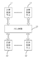
- FIG. 1 is a schematic structural diagram of a storage system according to an embodiment of the present invention.
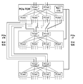
- FIG. 2 is a schematic diagram of a PCIe network in an embodiment of the present invention.
- FIG. 3 is a schematic diagram of another PCIe network in the embodiment of the present invention.
- FIG. 4 is a schematic structural diagram of a storage system according to another embodiment of the present invention.
- FIG. 5 is a schematic diagram of resource allocation in an embodiment of the present invention.
- FIG. 6 is a schematic diagram of another resource allocation in an embodiment of the present invention.
- FIG. 7 is a schematic diagram of another resource allocation in an embodiment of the present invention.
- FIG. 8 is a schematic diagram of another resource allocation in an embodiment of the present invention.
- FIG. 9 is a schematic diagram of another resource allocation in an embodiment of the present invention.
- FIG. 10 is a schematic diagram of another resource allocation in an embodiment of the present invention.
- FIG. 1 is a schematic structural diagram of a storage system according to an embodiment of the present invention, where the storage system includes:
- PCIe is an abbreviation for PCI-express
- PCI is a Peripheral Component Interconnect (PCI).
- the computing resource node 11 and the storage resource node 12 are physically separated and respectively connected to the PCIe network 13, and the PCIe network and the computing resource node and the storage resource node are Physically separate settings, and the computing resource node, the storage resource node and the PCIe network are all extensible.
- the number of computing resource nodes may be one or more, and the number of storage resource nodes may be one or more.
- the computing resource node may specifically be a PCIe Host (PCIe Host).
- the central processing unit In the traditional local storage scheme, the central processing unit (CPU) will usually be used. Hard Disk Drive (HDD) and Solid State Disk (SSD) are concentrated in a single physical chassis, and they cannot flexibly expand and change to meet different application requirements.
- HDD Hard Disk Drive
- SSD Solid State Disk
- the two are interconnected through the PCIe network. Since the computing resource node and the storage resource node, the PCIe network are independent and scalable, the flexibility can be improved.
- the front-end interface is usually an IP SAN or an FC SAN.
- the export bandwidth is limited, and the high performance of the SSD cannot be fully utilized.
- IP SAN networks have higher latency and FC SANs have higher costs.
- the storage resource node is directly allocated to the computing resource node through the PCIe network, and there is no additional storage protocol conversion overhead in the middle, and the interconnect bandwidth is very high, which can reduce the network delay, thereby realizing high-speed access of the storage resource, and cut costs.
- direct exposure of storage resources to computing resources makes it easier to integrate with existing distributed storage systems.
- the computing resource node can flexibly use the storage resource node according to its own needs, and utilize the storage resource more efficiently. For example, some storage resources are used as primary storage resources, and some SSDs are used as caches, and cache policies can be defined according to their own needs to truly implement a software-defined storage system.
- the PCIe network includes:
- the first level PCIe switch includes: at least one PCIe switch chip and one management module.
- the PCIe network further includes:
- At least one other level PCIe switch includes: at least one PCIe switch chip;
- the other level PCIe switch is connected to the management module.
- the PCIe switch chip in the other-stage PCIe switch is connected to the PCIe switch chip in the first-stage PCIe switch, and/or the PCIe switch chips in different other-stage PCIe switches are connected to each other.
- the PCIe network may be composed of one or more PCIe switches connected according to a certain topological relationship.
- a first-stage PCIe switch may be referred to as a PCIe TOR, and a PCIe TOR may include multiple PCIe switch chips (represented by PCIeX) and a management module (represented by a Mgmt CPU).
- PCIeX has PCIe switching capability, which can exchange data transmitted between computing resource nodes and storage resource nodes.
- Mgmt CPU is responsible for configuration management of PCIe network.
- a PCIe network may further include a multi-level PCIe switch.
- a multi-level PCIe switch scenario there is only one Mgmt CPU in the PCIe network.
- the Mgmt CPU can be connected to PCIe switch chips in different levels of PCIe switches.
- the PCIe network is constructed by using one or more PCIe switches, which may be different according to services. The need to flexibly build different PCIe networks.
- the storage resource node includes:
- a disk having an interface including at least one of the following: Serial Attached SCSI (SAS), Serial Advanced Technology Attachment (SATA), PCIe; wherein SCSI is a small computer system Interface (Small Computer System Interface).
- SAS Serial Attached SCSI
- SATA Serial Advanced Technology Attachment
- PCIe PCIe
- the storage controller has one end connected to the PCIe network and the other end connected to the disk.
- the form of the disk may be a hard disk drive (HDD) or a solid state disk (SSD). Therefore, the disk may include: SAS HDD, SAS SSD, SATA HDD, SATA SSD.
- the form of the disk is specifically SSD, so the disk can also be a PCIe SSD.
- the storage controllers can be different depending on the interface of the disk.
- the storage controller is a Host Bus Adapter (HBA) or a Redundant Array of Independent Disks (RAID) card.
- HBA Host Bus Adapter
- RAID Redundant Array of Independent Disks
- the storage controller's uplink port (the port connected to the PCIe network) is a PCIe port
- the downlink port includes SAS and/or SATA ports, which can support both SAS and SATA interfaces
- the storage controller is a PCIe switch chip.
- the uplink port of the storage controller is a PCIe port
- the downlink port is also a PCIe port.
- the uplink interface of the storage controller is a PCIe port
- the downlink port includes at least one of a PCIe port, a SAS port, and a SATA port, when the three types are included at the same time.
- the port can support both the disk of the SAS interface and the disk of the SATA interface and the disk of the PCIe port.
- the storage controller included in the storage system may be one or more types.
- the storage system includes: a storage controller including a PCIe port, a SAS port, and a SATA port, or
- the storage system includes: a storage controller that includes a SAS port and/or a SATA port, and a storage controller that is a PCIe port.
- the SAS/SATA interface (the interface may also be referred to as a port) and the PCIe interface are taken as an example.
- the storage resource node may be divided into a SAS/SATA interface resource node and a PCIe interface resource node.
- the SAS/SATA interface resource node and the PCIe interface resource node can exist simultaneously under the same PCIe network to support hybrid storage.
- the SAS/SATA interface resource node includes: an HBA or a RAID card (HBA/RAID). As a storage controller, one end is connected to the PCIe network, and the other end is connected to the disk.
- the disk may include at least one of the following items; SAS HDD, SAS SSD, SATA HDD, SATA SSD.
- HDD is mainly used for high-capacity storage applications to reduce storage costs.
- SSD is mainly used for IOPS type with certain requirements. Application to improve performance.
- the PCIe interface resource node includes: a PCIe switch, which is a storage controller, one end is connected to the PCIe network, and the other end is connected to the disk, and the disk includes: PCIe SSD.
- PCIe SSD with extremely high IOPS, can significantly improve the business performance of IOPS applications, such as databases.
- the disks of the SAS, SATA, and PCIe interfaces can be supported under the same PCIe network, and the storage medium of the disk can be Including HDD and SSD (for example, support for HDD and SSD in SAS or SATA interface, SSD support in PCIe interface), therefore, under the same PCIe network, SAS HDD, SAS SSD, SATA HDD, SATA SSD, PCIe SSD can Any combination of hybrid storage systems to support high-capacity storage applications to reduce costs, high-bandwidth, high-IOPS applications to improve business performance, and even support high-capacity, low-cost, high-bandwidth, and high IOPS Demand.
- HDD and SSD for example, support for HDD and SSD in SAS or SATA interface, SSD support in PCIe interface
- the PCIe network is further configured to:
- the PCIe network includes a management module (Mgmt CPU), when the disk of the storage resource node is a PCIe SSD, and the PCIe SSD is allocated to a computing resource node in a physical disk format, and a single physical disk is allocated to When a single computing resource node is used, the management module is used to:
- the PCIe network includes a management module (Mgmt CPU), when the disk of the storage resource node is a PCIe SSD, and the PCIe SSD is allocated to a computing resource node in a logical disk form, and a single logical disk is allocated to a single computing
- the resource node, the PCIe SSD includes a PCIe SSD controller supporting SR-IOV function.
- the PCIe SSD controller is configured to generate a VF, and divide the PCIe SSD into one or more logical blocks, and establish a mapping relationship between the logical block and the VF, where different VFs correspond to different logical blocks. ;
- the management module is configured to configure a correspondence between each computing resource node and each VF.
- the PCIe network includes a management module (Mgmt CPU), when the disk of the storage resource node is a PCIe SSD, and the PCIe SSD is allocated to a computing resource node in a logical disk format, and a single logical disk is simultaneously allocated to multiple
- the PCIe SSD includes a PCIe SSD controller supporting SR-IOV function when different computing resource nodes are used.
- the PCIe SSD controller is configured to generate a VF, and divide the PCIe SSD into one or more logical blocks, and establish a mapping relationship between the logical block and the VF, where at least one logical block corresponds to multiple VFs. ;
- the management module is configured to configure a correspondence between each computing resource node and each VF.
- the PCIe network includes a management module (Mgmt CPU), and the disk of the storage resource node is a disk of a SAS or SATA interface, and the disk of the SAS or SATA interface is allocated to a computing resource node in a physical disk format, and a single When the physical disk is allocated to a single computing resource node, the storage resource node further includes an HBA or a RAID controller supporting the SR-IOV function.
- Mgmt CPU management module
- the disk of the storage resource node is a disk of a SAS or SATA interface
- the disk of the SAS or SATA interface is allocated to a computing resource node in a physical disk format, and a single
- the storage resource node further includes an HBA or a RAID controller supporting the SR-IOV function.
- the HBA or the RAID controller is configured to generate a VF, and establish a mapping relationship between the disk of the SAS or SATA interface with a granularity of the physical disk and the VF, where different VFs correspond to different physical disks;
- the management module is configured to configure a correspondence between each computing resource node and each VF.
- the PCIe network includes a management module (Mgmt CPU), and the disk of the storage resource node is a disk of a SAS or SATA interface, and the disk of the SAS or SATA interface is allocated to a computing resource node in a logical disk format, and a single When the logical disk is allocated to a single computing resource node, the storage resource node further includes an HBA or a RAID controller supporting the SR-IOV function.
- Mgmt CPU management module
- the disk of the storage resource node is a disk of a SAS or SATA interface
- the disk of the SAS or SATA interface is allocated to a computing resource node in a logical disk format, and a single
- the storage resource node further includes an HBA or a RAID controller supporting the SR-IOV function.
- the HBA or RAID controller is configured to generate a VF, and divide the disk of the SAS or SATA interface into one or more logical blocks, and establish a mapping relationship between the logical block and the VF, where different VFs are used. Corresponding to different logic blocks;
- the management module is configured to configure a correspondence between each computing resource node and each VF.
- the PCIe network includes a management module (Mgmt CPU), and the disk of the storage resource node is a disk of a SAS or SATA interface, and the disk of the SAS or SATA interface is allocated to a computing resource node in a logical disk format, and a single When the logical disk is simultaneously allocated to a plurality of different computing resource nodes, the storage resource node further includes an HBA or a RAID controller supporting the SR-IOV function.
- Mgmt CPU management module
- the disk of the storage resource node is a disk of a SAS or SATA interface
- the disk of the SAS or SATA interface is allocated to a computing resource node in a logical disk format, and a single
- the storage resource node further includes an HBA or a RAID controller supporting the SR-IOV function.
- the HBA or RAID controller is configured to generate a VF, and divide the disk of the SAS or SATA interface into one or more logical blocks, and establish a mapping relationship between the logical block and the VF, where at least one logic The block corresponds to multiple VFs;
- the management module is configured to configure a correspondence between each computing resource node and each VF.
- a PCIe SSD can be supported as a physical disk to be allocated to a computing resource node (such as a PCIe host) on demand.
- a computing resource node such as a PCIe host
- any PCIe SSD is a separate PCIe device.
- the Mgmt CPU is responsible for the scanning and discovery of PCIe devices and PCIe hosts in the PCIe network, and configures the routing table of the PCIe network to statically or dynamically allocate specific PCIe devices to specific PCIe hosts according to the requirements of the PCIe host.
- PCIe SSDs there are four PCIe SSDs in the PCIe network.
- the PCIe is SSD A is assigned to computing resource node A
- PCIe SSD B, PCIe SSD C, and PCIe SSD D are assigned to computing resource node B.
- the complex PCIe physical network can be simplified into a logical PCIe Bridge, and the computing resource node can only see the PCIe Bridge, thus shielding the influence of the physical topology change on the computing resource node.
- a PCIe SSD can be supported to be allocated to a computing resource node as needed in a logical disk format.
- a PCIe SSD can be divided into multiple logical blocks, and then the logical blocks are allocated to different computing resource nodes, so that the management and allocation of resources can be performed with a smaller granularity to improve resource utilization.
- the physical disk PCIe SSD A is divided into examples, and the logical blocks after the splitting are referred to as SSD block A, SSD block B and SSD block C.
- a physical presence controller (PCIe SSD Controller) is provided in each PCIe SSD. When the controller supports single root I/O virtualization (SR-IOV), it can be logically formed. Multiple Virtual Functions (VF), each VF is a separate PCIe device in the PCIe network.
- SR-IOV single root I/O virtualization
- VF Virtual Functions
- the PCIe SSD Controller can map logical blocks to different VFs. For example, referring to Figure 6, SSD block A is mapped to VF-1, and SSD block B and SSD block C are mapped to VF-2.
- the Mgmt CPU is responsible for allocating different VFs to different computing resource nodes (the same VF cannot be assigned to multiple computing resource nodes). For example, referring to Figure 6, assigning VF-1 to computing resource node A, assigning VF-2 Give computing resource Node B. Therefore, the computing resource node A can access the SSD block A, and the computing resource node B can access the SSD block B and the SSD block C, so that the PCIe SSD is allocated to the computing resource node in a logical disk form as needed.
- multiple computing resource nodes can be simultaneously accessed to access the same PCIe SSD logic block.
- the PCIe SSD Controller can map the same SSD logic block to different VFs, and the Mgmt CPU is responsible for allocating VFs to different computing resource nodes. Therefore, different computing resource nodes can access the same PCIe SSD logic block at the same time to achieve data sharing. Multiple computing resource nodes can simultaneously read the same PCIe SSD logic block.
- the same PCIe SSD logic block can be written at the same time, but the consistency of the data requires the upper layer software to coordinate and guarantee.
- the PCIe SSD Controller maps the SSD block A and the SSD block B to the VF-1, the SSD block B and the SSD block C to the VF-2, and the Mgmt CPU allocates the VF-1 to the computing resource.
- the node A allocates the VF-2 to the computing resource node B, so that the computing resource node A and the computing resource node B can simultaneously access the SSD block B, thereby supporting multiple computing resource nodes to simultaneously access the same PCIe SSD logical block.
- a SAS/SATA interface disk can be supported as a physical disk to be allocated to a computing resource node as needed.
- HBA/RAID can include HBA/RAID Controller in hardware.
- HBA/RAID Controller does not support SR-IOV, it can only be managed as a PCIe device by Mgmt CPU. The disk on the back end is invisible to PCIe network. of. Therefore, all the disks connected to a certain HBA/RAID Controller can be allocated to a computing resource node as a whole. The granularity of resource allocation is large, and it is difficult to achieve efficient use of resources.
- the application is implemented in an scenario where the HBA/RAID Controller supports SR-IOV.
- the HBA/RAID Controller supports SR-IOV, it supports mapping different disks to different VFs.
- Each VF is a separate PCIe device in the PCIe network, and the Mgmt CPU is responsible for allocating VFs to different computing resource nodes.
- the same VF cannot be assigned to multiple compute resource nodes. Therefore, it is possible to indirectly implement different physical disks to be allocated to different computing resource nodes.
- the HBA/RAID Controller maps Disk-1 and Disk 2 to VF-1, Disk-3 and Disk-4 to VF-2, and the Mgmt CPU assigns VF-1 to Computing Resource Node A.
- the VF-2 is allocated to the computing resource node B, so that the computing resource node A can access the disk-1 and the disk-2, and the computing resource node B can access the disk-3 and the disk-4, thereby supporting the SAS/SATA interface disk. It is allocated to the computing resource node as needed in the form of a physical disk.
- a SAS/SATA interface disk can be supported as a logical disk to be allocated to a computing resource node as needed.
- the HBA/RAID Controller can aggregate one or more physical disks, divide it into one or more logical disks, and then map the logical disks to different VFs.
- Each VF is a separate PCIe device in the PCIe network, and the Mgmt CPU is responsible for allocating VFs to different compute nodes. Therefore, the management allocation of resources can be performed at a smaller granularity to improve resource utilization.
- the HBA/RAID Controller maps logical disk-1 and logical disk-2 to VF-1, logical disk-3 and logical disk-4 to VF-2, and Mgmt CPU will VF- 1 is allocated to the computing resource node A, and VF-2 is allocated to the computing resource node B, so that the computing resource node A can access the logical disk-1 and the logical disk-2, and the computing resource node B can access the logical disk-3 and the logic Disk-4, which supports the allocation of SAS/SATA interface disks to compute resource nodes as logical disks.
- multiple computing resource nodes can be simultaneously accessed to access the same logical SAS/SATA interface disk.
- the HBA/RAID Controller can map the same logical disk to different VFs, and the Mgmt CPU is responsible for allocating VFs to different computing resource nodes. Therefore, different computing resource nodes can access the same logical disk at the same time to achieve data sharing. Multiple computing resource nodes can simultaneously read the same logical disk. Technically, the same logical disk can be written at the same time, but the consistency of the data needs to be coordinated by the upper layer software.
- the HBA/RAID Controller maps logical disk-1 and logical disk-2 to VF-1, logical disk-2 and logical disk-3 to VF-2, and Mgmt CPU will VF- 1 is allocated to the computing resource node A, and the VF-2 is allocated to the computing resource node B, so that both the computing resource node A and the computing resource node B can access the logical disk-2, thereby supporting multiple computing resource nodes to simultaneously access the same Logical SAS/SATA interface disk.
- a physical disk or a logical disk may be allocated to the computing resource node by using a dynamic or static configuration, and different numbers and different types of storage resources may be configured according to the requirements of the computing resource node, which are flexible and changeable, and can satisfy each A variety of business needs.
- the number of storage resources allocated to the computing resource node can be dynamically increased or decreased.
- the number of storage resources such as PCIe SSD
- PCIe SSD PCIe SSD
- portions of the invention may be implemented in hardware, software, firmware or a combination thereof.
- multiple steps or methods may be implemented in software or firmware stored in a memory and executed by a suitable instruction execution system.
- a suitable instruction execution system For example, if implemented in hardware, as in another embodiment, it can be implemented by any one or combination of the following techniques well known in the art: having logic gates for implementing logic functions on data signals. Discrete logic circuits, application specific integrated circuits with suitable combinational logic gates, programmable gate arrays (PGAs), field programmable gate arrays (FPGAs), etc.
- each functional unit in each embodiment of the present invention may be integrated into one processing module, or each unit may exist physically separately, or two or more units may be integrated into one module.
- the above integrated modules can be implemented in the form of hardware or in the form of software functional modules.
- the integrated modules, if implemented in the form of software functional modules and sold or used as stand-alone products, may also be stored in a computer readable storage medium.
- the above mentioned storage medium may be a read only memory, a magnetic disk or an optical disk or the like.
Landscapes
- Engineering & Computer Science (AREA)
- Computer Networks & Wireless Communication (AREA)
- Signal Processing (AREA)
- Information Retrieval, Db Structures And Fs Structures Therefor (AREA)
Abstract
一种存储系统,该存储系统包括计算资源节点、存储资源节点和PCIe网络;其中,所述计算资源节点和所述存储资源节点分别连接到所述PCIe网络上,以及,所述PCIe网络、所述计算资源节点和所述存储资源节点在物理上均是分离设置的,且,都是可扩展的。该存储系统能够提高灵活性,提高存储资源的访问速度,并降低成本。进一步的,该存储系统还可以同时支持SAS、SATA和PCIe接口中至少一种接口的磁盘,并且,磁盘的存储媒介可以包括HDD和SSD,通过支持不同接口和不同存储媒介的磁盘,实现混合存储系统。另外,该存储系统可以通过动态或静态的配置为计算资源节点分配物理盘或逻辑盘,实现资源按需配置。
Description
相关申请的交叉引用
本申请要求北京百度网讯科技有限公司于2015年6月26日提交的、发明名称为“存储系统”的、中国专利申请号“201510369477.1”的优先权。
本发明涉及存储技术领域,尤其涉及一种存储系统。
不同的应用对存储资源的容量、带宽、每秒进行读写操作的次数(Input/output Per Second,IOPS)及可靠性有不同的需求,这给存储系统的设计带来了挑战。目前的存储系统通常有以下几种实现方案:本地存储,磁盘阵列+全闪存阵列,混合磁盘阵列。其中,本地存储是在服务器本地配备存储资源,但是由于不同磁盘的尺寸、形态、接口各异,需要针对不同应用设计不同的存储系统,可扩展性差,无法池化共享。磁盘阵列+全闪存阵列以及混合磁盘阵列方案中,需要经过映射或抽象,并在前端以互联网协议(Internet Protocol,IP)存储区域网络(Storage Area Network,SAN)或者网状通道(Fibre Channel,FC)SAN形式对外提供存储资源,在灵活性、带宽及成本等方面都存在不足。
发明内容
本发明旨在至少在一定程度上解决相关技术中的技术问题之一。
为此,本发明的一个目的在于提出一种存储系统,该系统可以提高灵活性,提高存储资源的访问速度,并降低成本。
为达到上述目的,本发明实施例提出的存储系统,包括:计算资源节点、存储资源节点和PCIe网络;其中,所述计算资源节点和所述存储资源节点在物理上分离设置,分别连接到所述PCIe网络上,以及,所述PCIe网络与所述计算资源节点和所述存储资源节点在物理上分离设置,且,所述计算资源节点,所述存储资源节点和所述PCIe网络都是可扩展的。
本发明实施例提出的存储系统,通过将计算资源节点和存储资源节点物理分离,二者通过独立设置的PCIe网络互联,且这些组成部分是可扩展的,可以提高灵活性;直接通过PCIe网络将存储资源节点分配给计算资源节点,可以提高存储资源的访问速度,并降低成
本。
本发明附加的方面和优点将在下面的描述中部分给出,部分将从下面的描述中变得明显,或通过本发明的实践了解到。
本发明上述的和/或附加的方面和优点从下面结合附图对实施例的描述中将变得明显和容易理解,其中:
图1是本发明一实施例提出的存储系统的结构示意图;
图2是本发明实施例中一种PCIe网络的示意图;
图3是本发明实施例中另一种PCIe网络的示意图;
图4是本发明另一实施例提出的存储系统的结构示意图;
图5是本发明实施例中一种资源分配的示意图;
图6是本发明实施例中另一种资源分配的示意图;
图7是本发明实施例中另一种资源分配的示意图;
图8是本发明实施例中另一种资源分配的示意图;
图9是本发明实施例中另一种资源分配的示意图;
图10是本发明实施例中另一种资源分配的示意图。
下面详细描述本发明的实施例,所述实施例的示例在附图中示出,其中自始至终相同或类似的标号表示相同或类似的模块或具有相同或类似功能的模块。下面通过参考附图描述的实施例是示例性的,仅用于解释本发明,而不能理解为对本发明的限制。相反,本发明的实施例包括落入所附加权利要求书的精神和内涵范围内的所有变化、修改和等同物。
图1是本发明一实施例提出的存储系统的结构示意图,该存储系统包括:
计算资源节点11、存储资源节点12和PCIe网络13;PCIe是PCI-express的简称,PCI是外设部件互连标准(Peripheral Component Interconnect,PCI)。
其中,所述计算资源节点11和所述存储资源节点12在物理上分离设置,分别连接到所述PCIe网络13上,以及,所述PCIe网络与所述计算资源节点和所述存储资源节点在物理上分离设置,且,所述计算资源节点,所述存储资源节点和所述PCIe网络都是可扩展的。
计算资源节点的个数可以是一个或者多个,存储资源节点的个数可以是一个或者多个。计算资源节点可以具体是PCIe主机(PCIe Host)。
传统的本地存储方案中,通常将将中央处理器(Central Processing Unit,CPU),机
械硬盘(Hard Disk Drive,HDD),固态硬盘(Solid State Disk,SSD)等集中在单一的物理机箱中,其无法灵活扩展变更以满足不同的应用需求。
本实施例中,通过将计算资源节点和存储资源节点物理分离,二者通过PCIe网络互联,由于计算资源节点,存储资源节点,PCIe网络是相互独立且可扩展的,可以提高灵活性。
传统的磁盘阵列+全闪存阵列或者混合磁盘阵列,其后端连接SAS、SATA接口的HDD和SSD,以及PCIe接口的SSD,经过抽象后,对外提供逻辑磁盘的访问服务。前端接口一般为IP SAN或者FC SAN,出口带宽有限,不能充分发挥SSD的高性能。IP SAN网络延时较高,而FC SAN成本较高。
本实施例中,直接通过PCIe网络将存储资源节点分配给计算资源节点,中间没有额外的存储协议转换开销,且互联带宽非常高,可以降低网络延时,从而实现存储资源的高速访问,并且可以降低成本。另外,直接将存储资源暴露给计算资源,更易于与现有的分布式存储系统融合集成。计算资源节点可根据自身需求来灵活使用存储资源节点,更高效的利用存储资源。如将部分存储资源作为主存储资源,另外部分SSD作为缓存(cache),并可根据自身需求来定义cache策略,真正实现软件定义的存储系统。
另一实施例中,所述PCIe网络包括:
第一级PCIe交换机,所述第一级PCIe交换机包括:至少一个PCIe交换芯片和一个管理模块。
可选的,所述PCIe网络还包括:
至少一个的其他级PCIe交换机,所述其他级PCIe交换机包括:至少一个PCIe交换芯片;
所述其他级PCIe交换机与所述管理模块连接;以及,
所述其他级PCIe交换机内的PCIe交换芯片与所述第一级PCIe交换机内的PCIe交换芯片连接,和/或,不同的其他级PCIe交换机内的PCIe交换芯片互相连接。
本实施例,PCIe网络可由一级或多级PCIe交换机按照一定的拓扑关系连接组成。
例如,参见图2,第一级PCIe交换机可以称为PCIe TOR,PCIe TOR内可以包括多个PCIe交换芯片(用PCIeX表示)以及一个管理模块(用Mgmt CPU表示)。PCIeX具有PCIe交换能力,能够交换计算资源节点与存储资源节点之间传输的数据,Mgmt CPU负责PCIe网络的配置管理。
又例如,参见图3,PCIe网络中还可以包括多级PCIe交换机。在多级PCIe交换机场景下,PCIe网络内也仅存在一个Mgmt CPU。Mgmt CPU可以连接到不同级的PCIe交换机内的PCIe交换芯片上。
本实施例中,通过采用一级或多级PCIe交换机构建PCIe网络,可以根据业务的不同
需求灵活构建不同的PCIe网络。
另一实施例中,所述存储资源节点包括:
磁盘,所述磁盘具有的接口包括如下项中的至少一项:串联连接SCSI(Serial Attached SCSI,SAS),串联增强技术连接(Serial Advanced Technology Attachment,SATA),PCIe;其中,SCSI是小型计算机系统接口(Small Computer System Interface)。
存储控制器,一端连接所述PCIe网络,另一端连接所述磁盘。
其中,当磁盘的接口是SAS或SATA时,磁盘的形态可以具体是机械硬盘(Hard Disk Drive,HDD)或固态硬盘(Solid State Disk,SSD),因此,磁盘可以包括:SAS HDD,SAS SSD,SATA HDD,SATA SSD。
当磁盘的接口是PCIe时,磁盘的形态具体是SSD,因此,磁盘还可以是PCIe SSD。
另外,根据磁盘的接口不同,存储控制器也可以是不同的。例如,当磁盘是SAS或SATA(简写为SAS/SATA)接口时,存储控制器是主机总线适配器(Host Bus Adapter,HBA)或者独立磁盘冗余阵列(Redundant Array of Independent Disks,RAID)卡,此时,存储控制器的上联端口(连接PCIe网络的端口)是PCIe端口,下联端口(连接磁盘的端口)包括SAS和/或SATA端口,可以同时支持SAS和SATA接口的磁盘;当磁盘是PCIe接口时,存储控制器是PCIe交换芯片(PCIe Switch),此时,存储控制器的上联端口是PCIe端口,下联端口也是PCIe端口。
可以理解的是,还可以存在一种存储控制器,该存储控制器的上联接口是PCIe端口,下联端口包括:PCIe端口,SAS端口和SATA端口中的至少一项,当同时包括这三种端口时,可以同时支持SAS接口的磁盘和SATA接口的磁盘以及PCIe端口的磁盘。
另外,可以理解的是,该存储系统中包括的存储控制器可以是一种或多种,例如,该存储系统包括:下联端口包括PCIe端口,SAS端口和SATA端口的存储控制器,或者,该存储系统包括:下联端口包括SAS端口和/或SATA端口的存储控制器,以及,下联端口是PCIe端口的存储控制器。
本实施例中,以区分SAS/SATA接口(接口也可以称为端口)和PCIe接口为例,参见图4,存储资源节点可以分为SAS/SATA接口资源节点和PCIe接口资源节点。另外,SAS/SATA接口资源节点和PCIe接口资源节点可以同时存在于同一个PCIe网络下,从而支持混合存储。
SAS/SATA接口资源节点包括:HBA或RAID卡(HBA/RAID),作为存储控制器,一端连接PCIe网络,另一端连接磁盘,磁盘可以包括如下项中的至少一项;SAS HDD,SAS SSD,SATA HDD,SATA SSD。
HDD主要用于大容量的存储应用以降低存储成本,SSD主要用于有一定要求的IOPS型
应用以提升性能。
PCIe接口资源节点包括:PCIe Switch,作为存储控制器,一端连接PCIe网络,另一端连接磁盘,磁盘包括;PCIe SSD。
PCIe SSD,具有极高的IOPS,可以显著提高IOPS应用场景的业务性能,如数据库。
本实施例中,通过将不同接口类型和/或不同存储媒介的存储资源节点连接到PCIe网络上,可以在同一个PCIe网络下支持SAS,SATA和PCIe接口的磁盘,并且,磁盘的存储媒介可以包括HDD和SSD(例如,在SAS或SATA接口时支持HDD和SSD,在PCIe接口时支持SSD),因此,在同一个PCIe网络下,SAS HDD,SAS SSD,SATA HDD,SATA SSD,PCIe SSD可以任意组合,实现混合存储系统,从而可支持大容量的存储应用以降低成本,也可以支持高带宽,高IOPS的应用以提升业务性能,甚至可以同时支持大容量、低成本、高带宽和高IOPS的需求。
另一实施例中,所述PCIe网络还用于:
将所述存储资源节点以物理盘或者逻辑盘形式分配给所述计算资源节点,其中,单一的物理盘或逻辑盘分配给单一的计算资源节点,或者,单一的物理盘或逻辑盘同时分配给多个不同的计算资源节点。
具体的,所述PCIe网络包括管理模块(Mgmt CPU),当所述存储资源节点的磁盘是PCIe SSD,且所述PCIe SSD以物理盘形式分配给计算资源节点,以及,单一的物理盘分配给单一的计算资源节点时,所述管理模块用于:
配置每个计算资源节点与以物理盘为粒度的每个PCIe SSD的对应关系。
或者,
所述PCIe网络包括管理模块(Mgmt CPU),当所述存储资源节点的磁盘是PCIe SSD,且所述PCIe SSD以逻辑盘形式分配给计算资源节点,以及,单一的逻辑盘分配给单一的计算资源节点时,所述PCIe SSD包括支持SR-IOV功能的PCIe SSD控制器,
所述PCIe SSD控制器用于生成VF,以及,将所述PCIe SSD划分为一个或多个逻辑块,并建立所述逻辑块与所述VF的映射关系,其中,不同的VF对应不同的逻辑块;
所述管理模块用于配置每个计算资源节点与每个VF的对应关系。
或者,
所述PCIe网络包括管理模块(Mgmt CPU),当所述存储资源节点的磁盘是PCIe SSD,且所述PCIe SSD以逻辑盘形式分配给计算资源节点,以及,单一的逻辑盘同时分配给多个不同的计算资源节点时,所述PCIe SSD包括支持SR-IOV功能的PCIe SSD控制器,
所述PCIe SSD控制器用于生成VF,以及,将所述PCIe SSD划分为一个或多个逻辑块,并建立所述逻辑块与所述VF的映射关系,其中,至少一个逻辑块对应多个VF;
所述管理模块用于配置每个计算资源节点与每个VF的对应关系。
或者,
所述PCIe网络包括管理模块(Mgmt CPU),当所述存储资源节点的磁盘是SAS或SATA接口的磁盘,且所述SAS或SATA接口的磁盘以物理盘形式分配给计算资源节点,以及,单一的物理盘分配给单一的计算资源节点时,所述存储资源节点还包括支持SR-IOV功能的HBA或RAID控制器,
所述HBA或RAID控制器用于生成VF,以及,建立以物理盘为粒度的SAS或SATA接口的磁盘与所述VF的映射关系,其中,不同的VF对应不同的物理盘;
所述管理模块用于配置每个计算资源节点与每个VF的对应关系。
或者,
所述PCIe网络包括管理模块(Mgmt CPU),当所述存储资源节点的磁盘是SAS或SATA接口的磁盘,且所述SAS或SATA接口的磁盘以逻辑盘形式分配给计算资源节点,以及,单一的逻辑盘分配给单一的计算资源节点时,所述存储资源节点还包括支持SR-IOV功能的HBA或RAID控制器,
所述HBA或RAID控制器用于生成VF,以及,将所述SAS或SATA接口的磁盘划分为一个或多个逻辑块,并建立所述逻辑块与所述VF的映射关系,其中,不同的VF对应不同的逻辑块;
所述管理模块用于配置每个计算资源节点与每个VF的对应关系。
或者,
所述PCIe网络包括管理模块(Mgmt CPU),当所述存储资源节点的磁盘是SAS或SATA接口的磁盘,且所述SAS或SATA接口的磁盘以逻辑盘形式分配给计算资源节点,以及,单一的逻辑盘同时分配给多个不同的计算资源节点时,所述存储资源节点还包括支持SR-IOV功能的HBA或RAID控制器,
所述HBA或RAID控制器用于生成VF,以及,将所述SAS或SATA接口的磁盘划分为一个或多个逻辑块,并建立所述逻辑块与所述VF的映射关系,其中,至少一个逻辑块对应多个VF;
所述管理模块用于配置每个计算资源节点与每个VF的对应关系。
例如,可以支持PCIe SSD以物理盘形式按需分配给计算资源节点(如PCIe主机)。在该PCIe网络内,任意一个PCIe SSD都是一个独立的PCIe设备。Mgmt CPU负责该PCIe网络内PCIe设备及PCIe主机的扫描、发现,并通过配置PCIe网络的路由表以将特定的PCIe设备按照PCIe主机的需求静态或者动态的分配给特定的PCIe主机。
本实施例中,参见图5,PCIe网络内有4个PCIe SSD,经过Mgmt CPU配置后,将PCIe
SSD A分配给了计算资源节点A,将PCIe SSD B、PCIe SSD C、PCIe SSD D分配给了计算资源节点B。另外,经过Mgmt CPU的配置,可以将复杂的PCIe物理网络简化为一个逻辑PCIe Bridge,计算资源节点只可以见到这个PCIe Bridge,因此可屏蔽物理拓扑的变化对计算资源节点的影响。
又例如,可以支持PCIe SSD以逻辑盘形式按需分配给计算资源节点。对于大容量的PCIe SSD,如果只能将整个盘全部分配给某个计算资源节点,则容量可能超过其需求,导致资源利用率低,最终导致成本浪费。本实施例中,可以将PCIe SSD切分为多个逻辑块,然后将逻辑块分配给不同的计算资源节点,因此可以更小的粒度来进行资源的管理分配,以提升资源利用率。
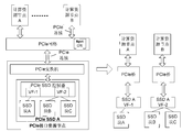
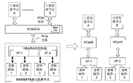
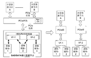
本实施例中,参见图6,以对物理盘PCIe SSD A进行切分为例,假设切分后的逻辑块称为SSD块A,SSD块B和SSD块C。在每个PCIe SSD内设置有物理存在的控制器(PCIe SSD Controller),当该控制器支持单一根I/O虚拟化(single root I/O virtualization,SR-IOV)时,可以在逻辑上形成多个虚拟功能(Virtual Function,VF),每个VF在PCIe网络中都是一个独立的PCIe设备。
PCIe SSD Controller可以将逻辑块映射到不同的VF,例如,参见图6,将SSD块A映射到VF-1,将SSD块B和SSD块C映射到VF-2。Mgmt CPU负责将不同的VF分配给不同的计算资源节点(同一个VF不能分配给多个计算资源节点),例如,参见图6,将VF-1分配给计算资源节点A,将VF-2分配给计算资源节点B。从而,计算资源节点A可以访问SSD块A,计算资源节点B可以访问SSD块B和SSD块C,实现了PCIe SSD以逻辑盘形式按需分配给计算资源节点。
又例如,可以支持多个计算资源节点同时访问同一个PCIe SSD逻辑块。PCIe SSD Controller可以将同一个SSD逻辑块映射到不同的VF,Mgmt CPU负责将VF分配给不同的计算资源节点。因此不同的计算资源节点可以同时访问同一个PCIe SSD逻辑块,以实现数据共享。多个计算资源节点可同时读取同一个PCIe SSD逻辑块,技术上可同时写同一个PCIe SSD逻辑块,但数据的一致性需要上层软件自行协调保证。
本实施例中,参见图7,PCIe SSD Controller将SSD块A和SSD块B映射到VF-1,将SSD块B和SSD块C映射到VF-2,Mgmt CPU将VF-1分配给计算资源节点A,将VF-2分配给计算资源节点B,从而可以实现计算资源节点A和计算资源节点B可以同时访问SSD块B,从而支持多个计算资源节点同时访问同一个PCIe SSD逻辑块。
当然,可以理解的是,当一个PCIe SSD的物理盘划分成一个逻辑块,则可以实现多个计算资源节点同时访问同一个物理盘。
又例如,可以支持SAS/SATA接口磁盘以物理盘形式按需分配给计算资源节点。
HBA/RAID在硬件上可以包括HBA/RAID Controller,当HBA/RAID Controller不支持SR-IOV时,其只能作为一个PCIe设备被Mgmt CPU所管理,其后端的磁盘对于PCIe网络来说是不可见的。因此此时只能将某个HBA/RAID Controller连接的所有磁盘作为一个整体分配给某个计算资源节点,资源分配的粒度较大,难以达到资源的高效利用。
本实施例中,应用在HBA/RAID Controller支持SR-IOV的场景下。当HBA/RAID Controller支持SR-IOV时,其支持将不同的磁盘映射到不同的VF。每个VF在PCIe网络中都是一个独立的PCIe设备,Mgmt CPU负责将VF分配给不同的计算资源节点。同一个VF不能分配给多个计算资源节点。因此可以间接实现将不同的物理磁盘分配给不同的计算资源节点。
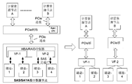
例如,参见图8,HBA/RAID Controller将磁盘-1和磁盘2映射到VF-1,将磁盘-3和磁盘-4映射到VF-2,Mgmt CPU将VF-1分配给计算资源节点A,将VF-2分配给计算资源节点B,从而可以实现计算资源节点A能够访问磁盘-1和磁盘-2,计算资源节点B能够访问磁盘-3和磁盘-4,从而支持将SAS/SATA接口磁盘以物理盘形式按需分配给计算资源节点。
又例如,可以支持SAS/SATA接口磁盘以逻辑盘形式按需分配给计算资源节点。HBA/RAID Controller可以将一个或多个物理磁盘进行聚合后,划分为一个或者多个逻辑磁盘,然后将逻辑磁盘映射到不同的VF。每个VF在PCIe网络中都是一个独立的PCIe设备,Mgmt CPU负责将VF分配给不同的计算节点。因此可以更小的粒度来进行资源的管理分配,以提升资源利用率。
本实施例中,参见图9,HBA/RAID Controller将逻辑磁盘-1和逻辑磁盘-2映射到VF-1,将逻辑磁盘-3和逻辑磁盘-4映射到VF-2,Mgmt CPU将VF-1分配给计算资源节点A,将VF-2分配给计算资源节点B,从而可以实现计算资源节点A能够访问逻辑磁盘-1和逻辑磁盘-2,计算资源节点B能够访问逻辑磁盘-3和逻辑磁盘-4,从而支持将SAS/SATA接口磁盘以逻辑盘形式按需分配给计算资源节点。
又例如,可以支持多个计算资源节点同时访问同一个逻辑SAS/SATA接口磁盘。HBA/RAID Controller可以将同一个逻辑磁盘映射到不同的VF,Mgmt CPU负责将VF分配给不同的计算资源节点。因此不同的计算资源节点可以同时访问同一个逻辑磁盘,以实现数据共享。多个计算资源节点可同时读取同一个逻辑磁盘,技术上可同时写同一个逻辑磁盘,但数据的一致性需要上层软件自行协调保证。
本实施例中,参见图10,HBA/RAID Controller将逻辑磁盘-1和逻辑磁盘-2映射到VF-1,将逻辑磁盘-2和逻辑磁盘-3映射到VF-2,Mgmt CPU将VF-1分配给计算资源节点A,将VF-2分配给计算资源节点B,从而可以实现计算资源节点A和计算资源节点B都能够访问逻辑磁盘-2,从而支持多个计算资源节点同时访问同一个逻辑SAS/SATA接口磁盘。
上述资源分配的实施例中,通过动态或静态的配置可以为计算资源节点分配物理盘或逻辑盘,可以按计算资源节点的需求配置不同数量及不同种类的存储资源,灵活多变,可满足各种不同业务的需求。可动态增减分配给计算资源节点的存储资源的数量,当业务需求激增时,可增加存储资源(如PCIe SSD)数量,以应对高峰需求;当业务需求下降时,可减少PCIe SSD数量,将其分配给其他的计算资源节点,提升资源利用率,降低系统总体成本。尤其适用于公有云平台中,可以灵活构建不同配置的服务器,可以在同一个平台中既支持大容量存储型应用,也可以支持高IOPS型应用,甚至支持存储容量及IOPS同时有需求的应用,以满足差异化且多变的公有云用户需求。
需要说明的是,在本发明的描述中,术语“第一”、“第二”等仅用于描述目的,而不能理解为指示或暗示相对重要性。此外,在本发明的描述中,除非另有说明,“多个”的含义是指至少两个。
流程图中或在此以其他方式描述的任何过程或方法描述可以被理解为,表示包括一个或更多个用于实现特定逻辑功能或过程的步骤的可执行指令的代码的模块、片段或部分,并且本发明的优选实施方式的范围包括另外的实现,其中可以不按所示出或讨论的顺序,包括根据所涉及的功能按基本同时的方式或按相反的顺序,来执行功能,这应被本发明的实施例所属技术领域的技术人员所理解。
应当理解,本发明的各部分可以用硬件、软件、固件或它们的组合来实现。在上述实施方式中,多个步骤或方法可以用存储在存储器中且由合适的指令执行系统执行的软件或固件来实现。例如,如果用硬件来实现,和在另一实施方式中一样,可用本领域公知的下列技术中的任一项或他们的组合来实现:具有用于对数据信号实现逻辑功能的逻辑门电路的离散逻辑电路,具有合适的组合逻辑门电路的专用集成电路,可编程门阵列(PGA),现场可编程门阵列(FPGA)等。
本技术领域的普通技术人员可以理解实现上述实施例方法携带的全部或部分步骤是可以通过程序来指令相关的硬件完成,所述的程序可以存储于一种计算机可读存储介质中,该程序在执行时,包括方法实施例的步骤之一或其组合。
此外,在本发明各个实施例中的各功能单元可以集成在一个处理模块中,也可以是各个单元单独物理存在,也可以两个或两个以上单元集成在一个模块中。上述集成的模块既可以采用硬件的形式实现,也可以采用软件功能模块的形式实现。所述集成的模块如果以软件功能模块的形式实现并作为独立的产品销售或使用时,也可以存储在一个计算机可读取存储介质中。
上述提到的存储介质可以是只读存储器,磁盘或光盘等。
在本说明书的描述中,参考术语“一个实施例”、“一些实施例”、“示例”、“具体示例”、
或“一些示例”等的描述意指结合该实施例或示例描述的具体特征、结构、材料或者特点包含于本发明的至少一个实施例或示例中。在本说明书中,对上述术语的示意性表述不一定指的是相同的实施例或示例。而且,描述的具体特征、结构、材料或者特点可以在任何的一个或多个实施例或示例中以合适的方式结合。
尽管上面已经示出和描述了本发明的实施例,可以理解的是,上述实施例是示例性的,不能理解为对本发明的限制,本领域的普通技术人员在本发明的范围内可以对上述实施例进行变化、修改、替换和变型。
Claims (13)
- 一种存储系统,其特征在于,包括:计算资源节点、存储资源节点和PCIe网络;其中,所述计算资源节点和所述存储资源节点在物理上分离设置,分别连接到所述PCIe网络上,以及,所述PCIe网络与所述计算资源节点和所述存储资源节点在物理上分离设置,且,所述计算资源节点,所述存储资源节点和所述PCIe网络都是可扩展的。
- 根据权利要求1所述的系统,其特征在于,所述PCIe网络包括:第一级PCIe交换机,所述第一级PCIe交换机包括:至少一个PCIe交换芯片和一个管理模块。
- 根据权利要求2所述的系统,其特征在于,所述PCIe网络还包括:至少一个的其他级PCIe交换机,所述其他级PCIe交换机包括:至少一个PCIe交换芯片;所述其他级PCIe交换机与所述管理模块连接;以及,所述其他级PCIe交换机内的PCIe交换芯片与所述第一级PCIe交换机内的PCIe交换芯片连接,和/或,不同的其他级PCIe交换机内的PCIe交换芯片互相连接。
- 根据权利要求1-3任一项所述的系统,其特征在于,所述存储资源节点包括:磁盘,所述磁盘具有的接口包括如下项中的至少一项:SAS,SATA,PCIe;存储控制器,一端连接所述PCIe网络,另一端连接所述磁盘。
- 根据权利要求4所述的系统,其特征在于,当所述磁盘是SAS或SATA接口时,所述存储控制器是HBA或者RAID卡,所述磁盘包括如下项中的至少一项:SAS HDD,SAS SSD,SATA HDD,SATA SSD。
- 根据权利要求4或5所述的系统,其特征在于,当所述磁盘是PCIe接口时,所述存储控制器是PCIe交换芯片,所述磁盘是PCIe SSD。
- 根据权利要求1-6任一项所述的系统,其特征在于,所述PCIe网络还用于:将所述存储资源节点以物理盘或者逻辑盘形式分配给所述计算资源节点,其中,单一的物理盘或逻辑盘分配给单一的计算资源节点,或者,单一的物理盘或逻辑盘同时分配给多个不同的计算资源节点。
- 根据权利要求7所述的系统,其特征在于,所述PCIe网络包括管理模块,当所述存储资源节点的磁盘是PCIe SSD,且所述PCIe SSD以物理盘形式分配给计算资源节点,以及,单一的物理盘分配给单一的计算资源节点时,所述管理模块用于:配置每个计算资源节点与以物理盘为粒度的每个PCIe SSD的对应关系。
- 根据权利要求7或8所述的系统,其特征在于,所述PCIe网络包括管理模块,当所述存储资源节点的磁盘是PCIe SSD,且所述PCIe SSD以逻辑盘形式分配给计算资源节点,以及,单一的逻辑盘分配给单一的计算资源节点时,所述PCIe SSD包括支持SR-IOV功能的PCIe SSD控制器,所述PCIe SSD控制器用于生成VF,以及,将所述PCIe SSD划分为一个或多个逻辑块,并建立所述逻辑块与所述VF的映射关系,其中,不同的VF对应不同的逻辑块;所述管理模块用于配置每个计算资源节点与每个VF的对应关系。
- 根据权利要求7-9任一项所述的系统,其特征在于,所述PCIe网络包括管理模块,当所述存储资源节点的磁盘是PCIe SSD,且所述PCIe SSD以逻辑盘形式分配给计算资源节点,以及,单一的逻辑盘同时分配给多个不同的计算资源节点时,所述PCIe SSD包括支持SR-IOV功能的PCIe SSD控制器,所述PCIe SSD控制器用于生成VF,以及,将所述PCIe SSD划分为一个或多个逻辑块,并建立所述逻辑块与所述VF的映射关系,其中,至少一个逻辑块对应多个VF;所述管理模块用于配置每个计算资源节点与每个VF的对应关系。
- 根据权利要求7-10任一项所述的系统,其特征在于,所述PCIe网络包括管理模块,当所述存储资源节点的磁盘是SAS或SATA接口的磁盘,且所述SAS或SATA接口的磁盘以物理盘形式分配给计算资源节点,以及,单一的物理盘分配给单一的计算资源节点时,所述存储资源节点还包括支持SR-IOV功能的HBA或RAID控制器,所述HBA或RAID控制器用于生成VF,以及,建立以物理盘为粒度的SAS或SATA接口的磁盘与所述VF的映射关系,其中,不同的VF对应不同的物理盘;所述管理模块用于配置每个计算资源节点与每个VF的对应关系。
- 根据权利要求7-11任一项所述的系统,其特征在于,所述PCIe网络包括管理模块,当所述存储资源节点的磁盘是SAS或SATA接口的磁盘,且所述SAS或SATA接口的磁盘以逻辑盘形式分配给计算资源节点,以及,单一的逻辑盘分配给单一的计算资源节点时,所述存储资源节点还包括支持SR-IOV功能的HBA或RAID控制器,所述HBA或RAID控制器用于生成VF,以及,将所述SAS或SATA接口的磁盘划分为一个或多个逻辑块,并建立所述逻辑块与所述VF的映射关系,其中,不同的VF对应不同的逻辑块;所述管理模块用于配置每个计算资源节点与每个VF的对应关系。
- 根据权利要求7-12任一项所述的系统,其特征在于,所述PCIe网络包括管理模块,当所述存储资源节点的磁盘是SAS或SATA接口的磁盘,且所述SAS或SATA接口的磁盘以逻辑盘形式分配给计算资源节点,以及,单一的逻辑盘同时分配给多个不同的计算资 源节点时,所述存储资源节点还包括支持SR-IOV功能的HBA或RAID控制器,所述HBA或RAID控制器用于生成VF,以及,将所述SAS或SATA接口的磁盘划分为一个或多个逻辑块,并建立所述逻辑块与所述VF的映射关系,其中,至少一个逻辑块对应多个VF;所述管理模块用于配置每个计算资源节点与每个VF的对应关系。
Applications Claiming Priority (2)
| Application Number | Priority Date | Filing Date | Title |
|---|---|---|---|
| CN201510369477.1A CN104965677B (zh) | 2015-06-26 | 2015-06-26 | 存储系统 |
| CN201510369477.1 | 2015-06-26 |
Publications (1)
| Publication Number | Publication Date |
|---|---|
| WO2016206198A1 true WO2016206198A1 (zh) | 2016-12-29 |
Family
ID=54219712
Family Applications (1)
| Application Number | Title | Priority Date | Filing Date |
|---|---|---|---|
| PCT/CN2015/090005 Ceased WO2016206198A1 (zh) | 2015-06-26 | 2015-09-18 | 存储系统 |
Country Status (2)
| Country | Link |
|---|---|
| CN (1) | CN104965677B (zh) |
| WO (1) | WO2016206198A1 (zh) |
Cited By (2)
| Publication number | Priority date | Publication date | Assignee | Title |
|---|---|---|---|---|
| CN111756828A (zh) * | 2020-06-19 | 2020-10-09 | 广东浪潮大数据研究有限公司 | 一种数据存储方法、装置及设备 |
| CN116033102A (zh) * | 2023-01-05 | 2023-04-28 | 广州广电运通金融电子股份有限公司 | 视频存储方法和视频播放方法 |
Families Citing this family (18)
| Publication number | Priority date | Publication date | Assignee | Title |
|---|---|---|---|---|
| CN105867842A (zh) * | 2016-03-23 | 2016-08-17 | 天津书生云科技有限公司 | 对存储系统的访问控制方法及装置 |
| CN105472047B (zh) * | 2016-02-03 | 2019-05-14 | 天津书生云科技有限公司 | 存储系统 |
| US10365981B2 (en) | 2016-08-19 | 2019-07-30 | Samsung Electronics Co., Ltd. | Adaptive multipath fabric for balanced performance and high availability |
| CN106776387B (zh) * | 2016-11-24 | 2019-10-18 | 大唐高鸿信安(浙江)信息科技有限公司 | 硬盘通道扩展装置 |
| CN106708745A (zh) * | 2016-12-05 | 2017-05-24 | 郑州云海信息技术有限公司 | 一种24盘位nvme动态分配结构及方法 |
| CN106990916B (zh) * | 2017-03-01 | 2020-04-07 | 北京腾凌科技有限公司 | 一种读写请求的处理方法及装置 |
| CN110515536B (zh) * | 2018-05-22 | 2020-10-27 | 杭州海康威视数字技术股份有限公司 | 数据存储系统 |
| US11436113B2 (en) * | 2018-06-28 | 2022-09-06 | Twitter, Inc. | Method and system for maintaining storage device failure tolerance in a composable infrastructure |
| CN109284258A (zh) * | 2018-08-13 | 2019-01-29 | 华东计算技术研究所(中国电子科技集团公司第三十二研究所) | 基于hdfs的分布式多级存储系统及方法 |
| CN111045602B (zh) * | 2019-11-25 | 2024-01-26 | 浙江大华技术股份有限公司 | 集群系统控制方法及集群系统 |
| US11573737B2 (en) * | 2020-03-02 | 2023-02-07 | Silicon Motion, Inc. | Method and apparatus for performing disk management of all flash array server |
| CN111930299B (zh) * | 2020-06-22 | 2024-01-26 | 中国建设银行股份有限公司 | 分配存储单元的方法及相关设备 |
| KR102555800B1 (ko) | 2021-04-06 | 2023-07-17 | 에스케이하이닉스 주식회사 | 스토리지 시스템 및 그 동작 방법 |
| KR102518287B1 (ko) | 2021-04-13 | 2023-04-06 | 에스케이하이닉스 주식회사 | PCIe 인터페이스 장치 및 그 동작 방법 |
| US11782616B2 (en) | 2021-04-06 | 2023-10-10 | SK Hynix Inc. | Storage system and method of operating the same |
| CN115145733A (zh) * | 2022-07-28 | 2022-10-04 | 阿里云计算有限公司 | 一种资源调配方法、装置、服务器和系统 |
| CN115686357B (zh) * | 2022-09-27 | 2026-05-05 | 苏州元脑智能科技有限公司 | 一种存储资源管理系统及存储系统 |
| CN120371549B (zh) * | 2025-06-27 | 2026-01-23 | 山东云海国创云计算装备产业创新中心有限公司 | 存储资源动态分配方法、装置、计算机设备及存储介质 |
Citations (3)
| Publication number | Priority date | Publication date | Assignee | Title |
|---|---|---|---|---|
| CN101299757A (zh) * | 2008-05-23 | 2008-11-05 | 华为技术有限公司 | 一种数据共享方法及通讯系统以及相关设备 |
| CN103312720A (zh) * | 2013-07-01 | 2013-09-18 | 华为技术有限公司 | 一种数据传输方法、设备及系统 |
| CN104639469A (zh) * | 2015-02-06 | 2015-05-20 | 方一信息科技(上海)有限公司 | 一种基于pcie互连的计算和存储集群系统 |
Family Cites Families (1)
| Publication number | Priority date | Publication date | Assignee | Title |
|---|---|---|---|---|
| JP4626582B2 (ja) * | 2006-07-03 | 2011-02-09 | ソニー株式会社 | カード型周辺機器およびカード通信システム |
-
2015
- 2015-06-26 CN CN201510369477.1A patent/CN104965677B/zh active Active
- 2015-09-18 WO PCT/CN2015/090005 patent/WO2016206198A1/zh not_active Ceased
Patent Citations (3)
| Publication number | Priority date | Publication date | Assignee | Title |
|---|---|---|---|---|
| CN101299757A (zh) * | 2008-05-23 | 2008-11-05 | 华为技术有限公司 | 一种数据共享方法及通讯系统以及相关设备 |
| CN103312720A (zh) * | 2013-07-01 | 2013-09-18 | 华为技术有限公司 | 一种数据传输方法、设备及系统 |
| CN104639469A (zh) * | 2015-02-06 | 2015-05-20 | 方一信息科技(上海)有限公司 | 一种基于pcie互连的计算和存储集群系统 |
Cited By (2)
| Publication number | Priority date | Publication date | Assignee | Title |
|---|---|---|---|---|
| CN111756828A (zh) * | 2020-06-19 | 2020-10-09 | 广东浪潮大数据研究有限公司 | 一种数据存储方法、装置及设备 |
| CN116033102A (zh) * | 2023-01-05 | 2023-04-28 | 广州广电运通金融电子股份有限公司 | 视频存储方法和视频播放方法 |
Also Published As
| Publication number | Publication date |
|---|---|
| CN104965677A (zh) | 2015-10-07 |
| CN104965677B (zh) | 2018-04-13 |
Similar Documents
| Publication | Publication Date | Title |
|---|---|---|
| CN104965677B (zh) | 存储系统 | |
| CN104657316B (zh) | 服务器 | |
| CN103503414B (zh) | 一种计算存储融合的集群系统 | |
| US10474624B2 (en) | Systems and methods for using resources in a networked computing environment | |
| US20250224999A1 (en) | Converged infrastructure system, non-volatile memory system, and memory resource acquisition method | |
| US20140195634A1 (en) | System and Method for Multiservice Input/Output | |
| JP7210554B2 (ja) | クラウド・ストレージをランクとして使用するストレージ・システム | |
| JP7116381B2 (ja) | クラウド・ベースのランクを使用するデータの動的再配置 | |
| US10581969B2 (en) | Storage system using cloud based ranks as replica storage | |
| US11086535B2 (en) | Thin provisioning using cloud based ranks | |
| KR20140111589A (ko) | 가상 기계들을 지원하는 플래시―기반 캐싱 해결책에서의 동적인 캐시 공유를 위한 시스템, 방법 및 컴퓨터―판독가능한 매체 | |
| EP2891051A1 (en) | Block-level access to parallel storage | |
| CN103561101A (zh) | 一种网络文件系统 | |
| EP1894103A2 (en) | Online restriping technique for distributed network based virtualization | |
| CN105657057A (zh) | 一种计算存储融合的集群系统 | |
| US9582218B2 (en) | Serial attached storage drive virtualization | |
| JP5996098B2 (ja) | ストレージデバイスの高速アクセス及びデータ保護を実現する計算機、計算機システム、及びi/o要求処理方法 | |
| CN104202359A (zh) | 一种基于刀片服务器的NVMe SSD虚拟化设计方法 | |
| CN107526545A (zh) | 一种分布式存储和集中式存储的资源整合办法 | |
| WO2016101856A1 (zh) | 数据访问方法及装置 | |
| CN115794296A (zh) | 基于硬件卸载的链接克隆方法、系统、设备及存储介质 | |
| CN205229915U (zh) | 一种用于融合架构支持nvme存储的刀片服务器架构 | |
| WO2014108935A1 (en) | Data storage system, method of controlling a data storage system and management system for a data storage system | |
| US11784916B2 (en) | Intelligent control plane communication | |
| WO2019223444A1 (zh) | 数据存储系统 |
Legal Events
| Date | Code | Title | Description |
|---|---|---|---|
| 121 | Ep: the epo has been informed by wipo that ep was designated in this application |
Ref document number: 15896093 Country of ref document: EP Kind code of ref document: A1 |
|
| NENP | Non-entry into the national phase |
Ref country code: DE |
|
| 122 | Ep: pct application non-entry in european phase |
Ref document number: 15896093 Country of ref document: EP Kind code of ref document: A1 |