WO2016202859A1 - Power inverter, control unit for power inverters and network of power inverters - Google Patents
Power inverter, control unit for power inverters and network of power inverters Download PDFInfo
- Publication number
- WO2016202859A1 WO2016202859A1 PCT/EP2016/063759 EP2016063759W WO2016202859A1 WO 2016202859 A1 WO2016202859 A1 WO 2016202859A1 EP 2016063759 W EP2016063759 W EP 2016063759W WO 2016202859 A1 WO2016202859 A1 WO 2016202859A1
- Authority
- WO
- WIPO (PCT)
- Prior art keywords
- power
- harmonics
- network
- harmonic
- control unit
- Prior art date
- Legal status (The legal status is an assumption and is not a legal conclusion. Google has not performed a legal analysis and makes no representation as to the accuracy of the status listed.)
- Ceased
Links
Classifications
-
- H—ELECTRICITY
- H02—GENERATION; CONVERSION OR DISTRIBUTION OF ELECTRIC POWER
- H02J—ELECTRIC POWER NETWORKS; CIRCUIT ARRANGEMENTS OR SYSTEMS FOR SUPPLYING OR DISTRIBUTING ELECTRIC POWER; SYSTEMS FOR STORING ELECTRIC ENERGY
- H02J3/00—Circuit arrangements for AC mains or AC distribution networks
- H02J3/01—Arrangements for reducing harmonics or ripples
-
- Y—GENERAL TAGGING OF NEW TECHNOLOGICAL DEVELOPMENTS; GENERAL TAGGING OF CROSS-SECTIONAL TECHNOLOGIES SPANNING OVER SEVERAL SECTIONS OF THE IPC; TECHNICAL SUBJECTS COVERED BY FORMER USPC CROSS-REFERENCE ART COLLECTIONS [XRACs] AND DIGESTS
- Y02—TECHNOLOGIES OR APPLICATIONS FOR MITIGATION OR ADAPTATION AGAINST CLIMATE CHANGE
- Y02E—REDUCTION OF GREENHOUSE GAS [GHG] EMISSIONS, RELATED TO ENERGY GENERATION, TRANSMISSION OR DISTRIBUTION
- Y02E40/00—Technologies for an efficient electrical power generation, transmission or distribution
- Y02E40/40—Arrangements for reducing harmonics
Definitions
- the invention generally relates to harmonics compensation in electrical systems, in particular, in electrical supply grids, such as, e.g. low or medium voltage power grids with distributed electrical power generation.
- EP 0965159 B1 discloses an active filter device suggesting the implementation of an active harmonics compensation of the load currents by injecting currents at 2 different frequencies varying with an offset from the harmonics frequencies to be compensated. A phase shift between line current and control voltage as well as the transfer function between the power module and the load are determined in order to generate the control signal at the frequency of the harmonic chosen to be compensated.
- EP1079493 B1 describes a method for harmonics compensation in electric power networks based on an implementation of an active harmonic compensation by subtracting the rectified load voltage and current from the initial load AC voltage and currents.
- EP2437383 A2 provides an active grid filter, suggesting the implementation of an active harmonic compensation for the application to the aircraft board electrical system based on the 3 to 2 phases Clarke transform of the measured current with the use of an adaptive low-pass filter to make the difference between reactive power and distortion power in order to compensate only the distortion power.
- WO1997049168 A1 discloses power line harmonic reduction by hybrid parallel active/passive filter system with square wave inverter and dc bus control.
- An active/passive filter system is implemented to reduce the harmonics in the current of high power (> 1 MW) non-linear loads in stiff supply system supplied with a square wave inverter.
- WO201 1032287 A1 describes a distributed power generation interface performing a harmonics free power injection out of renewable energy sources into the power distribution grid by use of resonant controllers, a wide band feed-forward harmonic compensator, a notch filter as well as PI current and power controllers.
- WO2002041463 A3 provides a system for correcting power factor and harmonics present on an electroduct in an active way and with high-dynamics, and suggests an implementation of a harmonic compensation based on Fast Fourier Transform (FFT) and an inverse FFT.
- FFT Fast Fourier Transform
- [001 1 ] DE 10032447 A1 suggests an electric current harmonic compensation method using a software program for analysing the network input current, with determination of selected harmonic components, for corresponding control of compensation regulators, providing additional voltages used with the voltage values for the network vector regulation, for providing an ideal voltage characteristic.
- DE 19819869 A1 discloses filtering out a basic oscillation from load currents in a first and a second cascade filter, and then filtering harmonics of any arbitrary order as discrete harmonics. The values produced are used for controlling an active harmonics filter, to generate a compensation current. The output values are combined to form a spatial vector, and three nominal currents for a pulsed current converter are formed by means of an inverse Clarke transformation.
- US 5648894 describes a system for compensation of harmonic distortion and neutral unbalance in a four-wire three phase power distribution system. To eliminate the respective harmonic components from the lines of the distribution system, an active power filter is provided. It includes a PWM inverter that provides compensating currents to the lines, respectively. Each compensating current equals the harmonic current components in its corresponding line, leaving only the fundamental component.
- a notch filter i.e. a band-stop filter that extracts with a high dynamic response any harmonics from a given signal, but needs two settings parameters to be optimised in function of the operating conditions for reaching the desired dynamic without oscillation.
- A. Salamah, S. Finney, B. Williams: "Three-phase phase-lock loop for distorted utilities”, IET Electrical Power Applications, 2007, 1 , (6), pp. 937-945 utilises a weighted least-square method based PLL using a Pl-controlled moving average that can become unstable in the case of a too narrow averaging window or to slow in the case of a too wide averaging window.
- a first aspect of the invention relates to a power inverter for converting one or more source currents into one or more alternating currents to be injected into an electrical supply grid.
- the power inverter according to the first aspect of the invention comprises a harmonics compensator configured to detect one or more harmonics of the fundamental frequency of the electrical supply grid and to control the one or more alternating currents to be injected into the electrical supply grid in such a way as to selectively modify the voltage of at least one of the one or more detected harmonics in accordance with one or more respective targets (e.g. setpoints or directions of modification such as "up” or “down”).
- the power inverter further comprises a communication interface, which allows it to join a network of power inverters.
- the harmonics compensator is connected to the communication interface and configured to share some or all of its operating parameters over the network and to adjust the one or more targets depending on instructions and/or operating parameters communicated to it via the network.
- harmonic designates an electric signal oscillating at a frequency that is an integer multiple (> 1 ) of the nominal (also: fundamental) frequency of the electrical supply grid.
- each harmonic is designated herein by the ordinal corresponding to that integer multiple: with n being an integer greater than 1 , the n-th harmonic has a frequency that is n times the frequency of the fundamental oscillation. In the present document, the fundamental oscillation is thus not considered as a harmonic.
- the power inverter is preferably adapted for an m-phase electrical supply grid, where m is 1 or 3.
- the supply grid may have 0, 1 or plural neutral conductors.
- the power inverter according to the first aspect of the invention allows harmonics compensation by a network of power inverters. It is one of the merits of the inventor to have recognized that harmonics compensation can be achieved in a more efficient way by a network of power inverters that exchange on their operating parameters.
- the operating parameters shared by the power inverter are indicative of the one or more targets applied by the harmonics compensator and/or of the electric powers delivered by the power inverter at each one of the one or more harmonics, respectively.
- the harmonics compensator comprises a plurality of harmonics control loops, each harmonics control loop being configured to control the voltage of a specific harmonic.
- the one or more targets may be the setpoints of the harmonics control loops.
- the one or more targets could simply be directions of modification communicated to the power inverter, such as e.g. desired increase or a decrease in the voltage of one or more of the detected harmonics.
- a power inverter may comprise a filter for detecting at least one harmonic in an electric signal.
- the filter may comprise a dedicated harmonics filter path for each harmonic to be detected.
- Each dedicated harmonics filter path preferably comprises a harmonic filter, the harmonic filter adapted to the respective harmonic, a harmonic detector, the harmonic detector adapted to the respective harmonic frequency and a harmonic controller, the harmonic controller adapted to control the electric signal at the respective harmonic frequency.
- a second aspect of the invention relates to a control unit for controlling a network of power inverters as generally described above.
- a control unit comprises: o a communication interface for communicating with the power inverters of the network and for receiving operating parameters of the power inverters shared by them over the network; and o a processor connected to the communication interface, the processor being configured to evaluate an objective function using the received operating parameters, and to dispatch instructions to power inverters of the network to provoke variations of the objective function, the instructions causing the power inverters of the network to adjust the one or more targets in accordance with which they modify the voltage of at least one of the one or more harmonics they detect.
- the processor could be a general-purpose microprocessor or microcontroller, an application-specific integrated circuit (ASIC), a programmable logic device (PLD), a field-programmable gate array (FPGA), or the like.
- ASIC application-specific integrated circuit
- PLD programmable logic device
- FPGA field-programmable gate array
- the objective function is a function, which maps the received operating parameters on a value that reflects a quality of the harmonics compensation. If the value has a negative connotation, one typically speaks of a cost function or a loss function (which are typically to be minimized). If the value has a positive connotation, the terms reward function or profit function (which are typically to be maximized) are used.
- the processor is preferably configured to generate the instructions in accordance with an optimisation algorithm concerning the objective function. If the objective function is a cost or loss function, the optimisation algorithm aims at minimising the value of the objective function. If the objective function is a reward or profit function, the optimisation algorithm aims at maximising the value of the objective function.
- the targets of the power inverters of the network may be considered to define an operational state of the network.
- the network follows a path through different operational states under the control of the control unit, which decides, in each operational state, how the targets of the power inverters are varied and which will thus be the next operational state.
- the optimisation algorithm may e.g. be a steepest- descent or steepest-ascent algorithm.
- the processor is configured to dispatch candidate instructions in an iterative manner to detect a variation of the current operational state that implies an improvement in terms of the objective function and to update the current operational state when such a variation is detected.
- testing candidate instructions may be an adequate way for the control unit to obtain information about the objective function in the neighbourhood of the current operational state at a specific time and to find the steepest gradient or at least a gradient reasonably close to the steepest gradient.
- the processor is preferably configured to evaluate the objective function separately for each harmonic and to optimise the objective function for each harmonic. That implies that the control unit may optimise compensation of each harmonic individually.
- the objective function reflects the total power delivered by the power inverters at each one of the one or more harmonics, respectively.
- each power inverter is preferably configured to transmit, as part of its operating parameters, the powers it delivers to the supply grid at each of the one or more harmonics, respectively.
- the control unit may then compute, for each harmonic, the total power as the sum of the individual powers received from the power inverters.
- the objective function is preferably the total apparent power at each harmonic.
- the processor is preferably configured to generate the instructions in accordance with an optimisation algorithm minimizing the total power delivered by the power inverters at each one of the one or more harmonics, respectively.
- the processor may be configured to maintain, for each harmonic, a schedule defining the order according to which the processor dispatches candidate instructions to the different power inverters of the network.
- the processor is further configured to dynamically modify the schedule depending on the operating parameters shared by the power inverters. Dynamic scheduling enables the processor to adapt itself to changing circumstances, such as increased or reduced harmonic distortions, varying geographical distribution of the harmonic distortions, failure of a power inverter, a power inverter becoming available, etc.
- the processor may be configured to maintain, for each harmonic, a ranking of the power inverters of the network that reflects the electric power delivered by the power inverters at that harmonic.
- the ranking may take the place of the schedule mentioned above.
- the processor is further preferably configured, for each harmonic, to dispatch candidate instructions more frequently to power inverters with a higher ranking than to power inverters with a lower ranking.
- the power inverters typically contribute to different extents to the compensation of a particular harmonic. By dispatching candidate instructions more frequently to power inverters making a greater contribution in the compensation of a harmonic, the processor ascertains that the optimisation algorithm converges quickly towards a satisfactory compensation of the harmonics when the current operational state of the network is far from optimal.
- a third aspect of the invention relates to a power inverter that comprises a control unit as described above.
- the control unit of the power inverter is configured to be placed into a master mode, in which the processor evaluates the objective function and dispatches instructions to power inverters of the network, and into a slave mode, in which the processor does not dispatch instructions to power inverters of the network.
- a fourth aspect of the invention relates to a network of power inverters, comprising a plurality of power inverters as described above and at least one control unit as described above.
- the at least one control unit may be integrated to at least one power inverter.
- the invention in its various aspects allows achieving harmonics compensation in a more efficient way than it was possible before.
- the invention may be used to minimise the total apparent power needed in the network to actively compensate the harmonics.
- a total harmonic distortion (THD) smaller than 8% in any load case, as required in the European norm EN50160, may be achieved without difficulty.
- THD is defined by the formula: where the sum runs over all harmonics n, V n is the voltage amplitude of the n-th harmonic and VF is the voltage amplitude of the fundamental frequency.
- Fig. 1 is a diagram illustrating grid voltage and current with and without harmonics compensation at a power transformer in overload.
- Fig. 2 is a diagram illustrating grid voltage and current with and without harmonics compensation at a power transformer at rated power.
- Fig. 3 is a diagram comparing the total harmonic distortion at no compensation and at cumulated harmonics compensation in overload and at rated power.
- Fig. 4 is an equivalent circuit diagram of a power network with two inverter-based voltage sources.
- Fig. 5 is an equivalent circuit diagram of a power network with a non-linear load an two inverter-based voltage sources.
- Fig. 6 is a graph of the relative distribution of the apparent power between the voltage sources of Fig. 5 as a function of the resistances difference R y -R, of the grid line sections j and i respectively.
- Fig. 7 is an equivalent circuit diagram of a power network with three voltage source inverters and one non-linear load.
- Fig. 8 is a graph illustrating different distributions of the compensation power among three VSIs that result when the VSI closest to the non-linear load runs at nominal power , at part power and at overpower
- Fig. 9 is a schematic illustration of a power network with power inverters connected to form a communication network.
- Fig. 10 Is an illustration of an example of possible distributions of the compensation powers among the power inverters of Fig. 9.
- Fig. 1 1 is a graph illustrating the total compensation power as a function of the power coefficient of the VSI closest to the non-linear load when the power coefficients of the other VSIs are set to 1 .
- Fig. 12 is a simplified flow chart of an optimisation algorithm implemented by a control unit or a master power inverter together with the slave power inverters of its network.
- Fig. 13 is an illustration of a convergence path of a simplified optimisation algorithm for a simulated network of power inverters.
- Fig. 14 is an illustration of the decision process of the optimisation algorithm.
- Fig. 15 is a comparison of convergence paths obtained for different optimisation methods where a new operation point is selected as soon as the global apparent power has become lower starting with the inverter i (left graph) or starting with the inverter j (right graph) and not after having tested all the possible operating points and selected the best one.
- Fig. 16 is an illustration of convergence paths resulting when one of the power inverters involved is limited in the compensation power it can deliver to the grid and when the limitation ceases to exist.
- Fig. 17 is a schematic block diagram of a power inverter capable of harmonics compensation according to the first aspect of the invention.
- Fig. 18 is a schematic block diagram of a power inverter comprising a control unit according to the second aspect of the invention.
- Fig. 19 is a more detailed block diagram of a power inverter configured and arranged for a 3-phase grid.
- Fig. 20 is a more detailed block diagram of a power inverter configured and arranged for a single-phase grid.
- Fig. 21 is a schematic block diagram of a power network with several power inverters organised in geographical clusters.
- Fig. 1 is a diagram illustrating grid voltage and current at a power transformer in overload.
- the voltages and currents with and without harmonics compensation are drawn offset from one another: the grid voltage and current without harmonics compensation are drawn shifted upwards, whereas the grid voltage and current with harmonics compensation are shown shifted downwards.
- Fig. 2 illustrates grid voltage and current with and without harmonics compensation at a power transformer at rated power.
- the grid voltage and current without harmonics compensation is drawn shifted upwards, whereas the grid voltage and current with harmonics compensation is shown shifted downwards.
- Figs. 1 and 2 show the differences in the shapes of the voltage and the current vs. time at the phases of an power transformer in overload and at rated power with and without harmonics compensation when the power supply feeds in a non-linear load like TV or ICT servers.
- the feedback effect of the non-linear load on the output voltage of the transformer depends on the rated power of the transformer: The lower the rated power, the higher is the feedback effect.
- the left-hand chart of Fig. 3 compares the THD without compensation (leftmost bar) with the THDs obtained with compensation turned on for specific harmonics in overload.
- the right-hand chart shows the same at rated power.
- Fig. 3 shows that it is possible to achieve THD ⁇ 8%, as required in the European norm EN50160, if the lower harmonics are appropriately compensated. Thanks to the invention, that can now be done in a more efficient way.
- o a is the actual fundamental frequency of the grid (e.g. between 49.5 Hz and 50.5 Hz in accordance with quality standard EN50160 for 50-Hz power grids; is the harmonic order of the voltage or the current (for sake of simplicity, the fundamental wave is numbered 1 ).
- the distortion power can be reduced by reducing the harmonics voltage magnitudes
- the distortion power can be compensated by one inverter alone or several inverters distributed along the grid line.
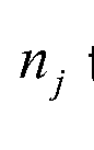
- Fig. 4 shows two inverter-based voltage sources connected to the grid, generating at the nodes n and the complex voltages with phase shifts
- harmonic m Complex values are denoted by macrons (diacritical bars placed above the respective letters).
- the grid line on this section has a conductance G m and a susceptance for the harmonic m.
- the complex power of the harmonic m is thus defined by the differences of the voltage magnitudes and of the voltage phase shifts of the voltage sources.
- the complex power of the harmonic m is zero when the voltage magnitudes and phase shifts of both voltage sources are equal.
- Fig. 5 shows the equivalent circuit of two voltage source inverters VSI, and VSIj connected to a non-linear load (i.e. a source of harmonic distortions) over the line of a resistive low-voltage grid.
- the grid line section between VSI, (resp. VSIj) and the load has the resistance represents the impedance of the
- VSI, and VSIj generate voltages uvsi ⁇ and uvsiim , respectively, in order to reduce the load voltage of harmonic m to 0 (like a short circuit) and thus to compensate the distortion power of harmonic m.
- the voltages and the currents of the VSI's fulfil:
- Fig. 6 shows the relative distribution of the apparent power (the magnitude of the complex power) between VSI, and VSIj of Fig. 5 as a function of the difference (increasing from left to right).
- Fig. 7 shows the equivalent circuit of three voltage source inverters VSI,, VSIj and VSIk connected to a non-linear load over the line of a resistive low-voltage grid.
- VSI is close to the load and it is assumed that the impedance of the grid line section between VSI, and the load is negligible VSIj is more distant from the load than
- q Um is a power coefficient predefining the compensation power ratio that VSI, can actually generate for the harmonic m (index denotes the number of the
- VSI and index the harmonic order means that VSI, runs at
- nominal power for harmonic means that VSI, runs at partial power for harmonic m and means that VSI, runs at overpower for harmonic m.
- the power coefficient q i m may take different values for the different harmonics. Accordingly, the distribution of the compensation power among the VSIs may be different for each harmonic.
- Fig. 9 shows a power grid with a non-linear load and several VSIs (VSh, VSI2, VSI3, ...) connected to the grid line at different distances from the non-linear load. Absent any active control of the compensation power provided by each VSI, the overall compensation power is naturally distributed between the VSIs depending on their respective distance from the non-linear load and power capacity ( The sum of the individual compensation
- the VSIs are connected to form a communication network allowing the VSIs to communicate with one another and/or with a control unit (not shown).
- the control unit may be part of a VSI, in which case that VSI may be termed the master VSI and the other VSIs the slave VSIs.
- the required compensation power can be arbitrarily distributed between the VSIs taking only their current power capacity into consideration for efficiency optimisation purpose.
- a criterion for adjusting the different compensation powers may be the reduction of the overall power losses due to the line resistance over the whole grid.
- Minimising the power losses may be achieved by increasing the compensation power generated by the VSI closest to the non-linear load, if that VSI has the required power capacities. The more distant VSIs are involved to a lesser extent in the compensation (than they would be in the case of a natural distribution of the compensation power) or not at all.
- Controlling the VSI may be subordinate to several priorities and/or requirements.
- One requirement/priority may be that the harmonics compensation by the VSIs gives precedence to the harmonics with the highest voltage amplitudes (typically the low-order harmonics).
- a further requirement may be that the THD remains below a threshold, e.g. 8% as required by quality standard EN50160.
- Fig 10 illustrates an example of possible distributions of the compensation powers among the VSIs of Fig. 9, for different harmonics.
- VSh compensates only 80% of the 5 th harmonic. The remaining 20% are taken over by As
- VSh e.g. because of limitation of the available power.
- VSb is in overpower on the 1 1 th harmonic In the Example, it compensates 100% of the 1 1 th harmonic.
- the other VSIs spend no compensation power on the 1 1 th harmonic
- the compensation by other VSIs possibly connected to the grid can be put into stand-by.
- the VSIs may be actively controlled by the control unit or they may compensate those harmonics autonomously (i.e. without relying on information on the operating parameters of the other VSIs or on instructions provided by the control unit, for instance in case of a communication failure between the master and the slaves).
- the VSI closest to the non-linear load provides a higher-than-natural compensation power while the more distant VSIs provide lower-than-natural compensation powers.
- the distribution of the compensation powers is ideally such that the total compensation power perfectly matches the distortion power to be compensated.
- Fig. 1 1 shows the total compensation power (i.e. the sum of all compensation powers produced by the VSIs) as a function of q (the power coefficient of the VSI
- An operating point of the network of VSIs is defined by the vector
- control unit preferably implements a dynamic optimisation algorithm, which takes into account how the grid reacts to (small) changes of the operating point.
- VSh is supposed to be the master VSI, whereas the other VSIs are slave VSIs.
- the master VSI comprises a control unit with (a) a communication interface for communicating with the other VSIs of the network and for receiving the operating parameters they share over the network and (b) a processor configured to evaluate a cost function using the received operating parameters as inputs, and to dispatch instructions to the VSIs to provoke variations of the cost function.
- each V shares, as its operating parameters, the complex compensation powers s VSIJ rn which it injects into the grid for the different harmonics m.
- Each VSIj derives the complex compensation powers s VSIJ rn (with magnitudes s VSIjiTn ) from the corresponding complex currents and voltages (step S1201 ). Instead of transmitting the complex powers, the VSIs could transmit the corresponding current and voltage values.
- the (control unit of the) master VSI computes (step S1202) the total compensation power for each harmonic m that it actively compensated as
- the total apparent compensation power s SVItotaljn defines the cost function, which the control unit tries to reduce by adjusting the individual power coefficients q Um of the VSIs.
- control unit implements a steepest descent algorithm (steps S1203, S1204, S1205), by testing which small variation
- the control unit dispatches instructions to the VSIs of the network, which causes them to adjust the targets in accordance with which they modify the voltage of each harmonic m they detect.
- the control unit transmits the variations Aq J m of the power coefficients that have to be applied by the VSIs that are addressed (step 1206).
- each VSIj listens to the messages from the master VSI (or the standalone control unit) and reads the value Aq J m that is intended for it (step 1207). It is worthwhile noting that, at a given time, the variation Aq J m may be zero for many VSIs. In this case, the control unit does not need to address those VSIs at that time.
- the VSIj addressed Upon receipt of an instruction to apply Aq JiTn , the VSIj addressed applies a setpoint variation of the voltage of harmonic m (step S1208):
- u VSIjm being the voltage that VSIj had to apply to steer the voltage of harmonic m to
- the algorithm could be started from any initial operating point q. Preferably, however, it is started at meaning that each VSI tries to drive the
- Fig. 13 shows the convergence path of a simplified optimisation algorithm for a simulated network of VSIs. Only two VSIs have been actively controlled by the control unit, the other ones were left running at their nominal compensation power. The reason for this simplification is that the path becomes three-dimensional with three centrally controlled VSIs, four-dimensional with four centrally controlled VSIs, etc., making it difficult to visualise such a path.
- Fig. 13 shows the isolines of the cost function. In the illustrated case, the cost function was known globally (i.e. for all theoretically possible operating points), since all relevant parameters were entered into the simulation. In a real situation, the cost function is not globally known and, furthermore, may change over time. Fig. 13 shows that the operating point of the network roughly follows the steepest descent to the minimum of the cost function (around
- Fig. 14 illustrates that, at each operating point, the algorithm tests different candidate variations among which it selects the one that results in the steepest descending slope (see also step 1203 in Fig. 12).
- the slope is calculated as:
- Aq max is the maximum allowed step size (e.g. between 1 %
- Aq max is kept constant. In more elaborate versions of the algorithm, may be able to vary over
- the control unit Before testing the candidate instructions at an operating point, the control unit determines a ranking of the VSIs in accordance with the apparent power they supply to the grid for the given harmonic m.
- the algorithm gives precedence to variations of the power coefficient of the VSI providing the highest compensation power, i.e. the closest to the non-linear loads, because that power coefficient has the greatest impact on the total compensation power in comparison to the power coefficients of the other VSIs.
- Fig. 15 illustrates a variant of the algorithm of Figs. 13 and 14, which differs from that algorithm described above in that a new operation point is selected as soon as a candidate operating point is found for which the global apparent power is lower, and not only after having tested all the available candidate operating.
- the algorithm converges on different paths if the optimisation algorithm gives a higher priority to the variation of the power coefficient of VSh, the VSI closest to the non-linear load (graph on the left), or to the power coefficient of VSIj, the VSI more distant from the non-linear load (graph on the right).
- the path thus depends on the order of testing the VSIs.
- Fig. 16 illustrates what happens if one of the centrally controlled VSIs is not capable of providing the full compensation power: the optimisation algorithm routes the remaining VSI towards another operating point. When all VSIs are fully operational again, the algorithm converges to the optimal operating point.
- VSh is running at limited compensation power (qi, m ⁇ 80%), which causes the control unit to run VSb with increasing q2, m .
- VSh is no longer limited in compensation power
- its power coefficient is increased by the control unit.
- the power coefficient q2, m of VSb is decreased, so that the algorithm converges towards the optimal operating point known from Figs. 13 and 15.
- the right graph of Fig. 16 shows the same scenario with the roles of VSh and VSb inverted.
- Fig. 17 schematically illustrates a possible embodiment of a (slave) VSI 10 for converting a DC source current into alternating current.
- the VSI 10 comprises a harmonics compensator 12 configured to detect one or more harmonics of the fundamental frequency of the electrical supply grid and to control the alternating current(s) to be injected into the electrical supply grid in such a way as to selectively drive the voltage amplitude of the harmonics towards respective setpoints.
- the VSI 10 further comprises a communications module 14, which allows the VSI 10 to join the network of VSIs.
- the harmonics compensator 12 is connected to the communications module to send the currently measured complex compensation power over the network and to adjust its setpoints for the different harmonics depending on instructions and communicated to it by a control unit.
- Fig. 18 schematically shows a (master) VSI 20 with an integrated control unit 22 for controlling the network of VSIs.
- the control unit 22 is comprised of a communications module 24 and a microcontroller 26.
- the microcontroller 26 is connected to the communication interface and evaluates a cost or profit function using the operating parameters received from the slave VSIs.
- the microcontroller 26 further dispatches the instructions to the slave VSIs, which causes them to adjust their power coefficients and thereby provoke variations of the cost or profit function.
- Figs. 19 and 20 show the structures of preferred embodiments of the harmonics compensators 12 (Fig. 17) and 28 (Fig. 18) in more detail.
- Fig. 19 shows a VSI adapted for a 3-phase grid whereas
- Fig. 20 shows a VSI adapted for a single- phase grid.
- the harmonics compensators of Figs. 19 and 20 use finite impulse response (FIR) filters to separate the fundamental oscillation and the individual harmonics. It should be noted, however, that other filter types could be used as well.
- FIR finite impulse response
- Each harmonic is compensated using a dedicated, phase-locked-loop (PLL) based compensation path.
- PLL phase-locked-loop
- the voltage magnitude and frequency setpoints are equal to the utility grid voltage magnitude and frequency in grid-tied mode or fixed to a given value in standalone mode or is provided by a droopl static (e.g. frequency vs. inverter active power P produced and voltage magnitude vs. inverter reactive power Q exchanged).
- a droopl static e.g. frequency vs. inverter active power P produced and voltage magnitude vs. inverter reactive power Q exchanged.
- a pulse width modulator (PWM) 30 get as input values the voltages ui , U2, U3 to be generated.
- the firing signals from the PWM 30 feed a basic voltage source inverter circuit 32, which is supplied with a DC supply voltage UDC
- the three-phase output of the circuit 32 is fed through a passive filter network 34 to the primary side of a power transformer 36.
- the secondary side of the power transformer 36 is connected through an electric power supply network to an electrical load 38 and a utility grid 40.
- the feedback network provides a signal path 5001 dedicated to the fundamental frequency, as well as, parallel thereto, further signal paths 5005, 5007, 501 1 , 5013, 5017, 50_n, each of which is adapted and dedicated to a specific harmonic frequency.
- Each signal path comprises a frequency filter 44 adapted to the respective frequency.
- Each filter path further comprises a frequency detector 46 adapted to the respective frequency.
- each filter path comprises a controller 48 producing output variables that reduce the error between the signals entered as the process variables and the setpoints. [0090]
- Each filter 44 receives the three power supply phases U3act, filters
- Each frequency detector 46 comprises a PLL, adapted and dedicated to the respective frequency. Each PLL receives the FIR filter outputs U i FiRm, U2FiRm, U3FiRm and a respective frequency setpoint (fsetpordm) as inputs. The outputs Udordm, u q ordm of each frequency detector 46 correspond to the direct and quadrature components of the voltage at the respective frequency.
- Each controller 48 comprises a PI controller.
- Each PI controller is adapted and dedicated to the respective frequency.
- Each PI controller receives the outputs of the corresponding frequency detector 46 and a voltage setpoint (defined by the direct component setpoint Udsetpordm and the quadrature component setpoint u q set P ordm in the Park coordinates system).
- each PI controller outputs voltages Udctrioutordm and u q ctrioutordm corresponding to the direct and quadrature components of the compensation output voltage in the Park coordinates system.
- both a PARK inverse function 52 and a CLARK inverse function 54 are provided to transform the PI controller output back into three sinusoidal signals u i ordm, U20rdm, U30rdm spaced by 1 20° (with respect to the fundamental frequency).
- Fig. 20 relates to the case of a 1 -phase power network or grid. In this case, the 3 RD harmonic needs to be compensated.
- a pulse width modulator (PWM) 60 gets as input value the voltage u to be generated.
- the firing signals produced by the PWM 60 feed a single-phase voltage source inverter circuit 62, which is supplied with a supply voltage UDC
- the single-phase output of circuit 62 is fed through a passive filter network 64 to the primary side of a power transformer 66.
- the secondary side of the power transformer 66 is connected through an electric power supply network to an electrical load 68 and a utility grid 70.
- the power supply phase u ac t is detected by sensor 72 and is fed into the compensation paths.
- the feedback network provides a signal path 8001 dedicated to the fundamental frequency, as well as, parallel thereto, further signal paths 8003, 8005,... 80_m, each of which is adapted and dedicated to a specific harmonic frequency.
- Each signal path comprises a frequency filter 74 adapted to the respective frequency.
- Each filter path further comprises a frequency detector 76 adapted to the respective frequency.
- each filter path comprises a controller 78 producing output variables that reduce the error between the signals entered as the process variables and the setpoints.
- Each filter 74 filters the single phase power supply voltage so as to extract the respective fundamental or harmonic frequency, and provides a filtered output signal UFiRk, where k is 1 for the fundamental or 3, 5, 7, etc. for the harmonics.
- Each frequency detector 76 comprises a PLL, adapted and dedicated to the respective frequency.
- Each PLL receives the FIR filter outputs UFiRk and a respective frequency setpoint (fsetpordk) as inputs.
- the outputs Udordk, u q ordk of each frequency detector 76 correspond to the direct and quadrature components of the voltage at the respective frequency.
- Each controller 78 comprises a PI controller adapted and dedicated to the respective frequency.
- Each PI controller receives the outputs of the corresponding frequency detector 76 and a voltage setpoint (defined by the direct component setpoint Udsetpordk and the quadrature component setpoint u q set P ordk).
- each PI controller outputs voltages Udctrioutordk and u q ctrioutordk corresponding to the direct and quadrature components of the compensation output voltage.
- a Polar-to-Cartesian transformation 82 is provided to transform the PI controller output into a sinusoidal signal uordk.
- Udctrioutordk and Uqctrioutordk are the two components of the voltage vector in a coordinates system rotated by angle pordk. The voltage vector is thus represented through its polar coordinates, i e
- Fig. 21 illustrates a power network, wherein the VSIs are organised in zones.
- the VSIs form a cluster with one central control unit (or one master VSI).
- the VSIs of one zone can contribute to the harmonics compensation of another zone, for instance, when the VSI's of that zone do not have enough power available to compensate all the harmonics.
- a zone of VSIs may be defined by a given maximum distance of the VSIs to each other.
- the total compensation power in one zone is the sum of all the compensation powers provided by the VSIs of that zone.
- Every VSI communicates its currently produced compensation power to the master VSI or to the control unit, which calculates the total compensation power, ranks the VSIs in accordance with their compensation powers, determines the variations of the power coefficients and sends the corresponding instructions to the VSIs of its zone.
- the VSIs may be configured to be able to take both the role of the master VSI and the role of the slave VSI.
- a conflict resolution algorithm may be used to establish that there is only one master VSI per cluster or zone. All but one VSI equipped for acting as the control unit are then switched into slave mode. If the current master VSI fails (stops working or stops communicating), one of the remaining VSIs with master capability may take over the master tasks. Again, the conflict resolution algorithm may be used to determine which one of the remaining VSIs becomes the master.
- the optimisation algorithm may set their power coefficients sequentially to a still lower level in order to determine their contribution in the total compensation power balance. If the total compensation power becomes worse, the optimisation algorithm sets the related power coefficient to its original value.
Landscapes
- Engineering & Computer Science (AREA)
- Power Engineering (AREA)
- Inverter Devices (AREA)
- Supply And Distribution Of Alternating Current (AREA)
Abstract
According to a first aspect of the invention, a power inverter for converting source currents or voltages into alternating currents or voltages to be injected into a supply grid comprises a harmonics compensator configured to detect one or more harmonics of the fundamental frequency of the electrical supply grid and to control the alternating currents or voltages to be injected in such a way as to selectively modify the voltage of at least one of the one or more detected harmonics in accordance with one or more respective targets. A communication interface allows the power inverter to join a network of power inverters. The harmonics compensator is configured to share some or all of its operating parameters over the network and to adjust the one or more targets depending on instructions and/or operating parameters communicated to it via the network. A second aspect of the invention relates to a control unit for centrally controlling such power inverters.
Description
POWER INVERTER, CONTROL UNIT FOR POWER INVERTERS AND NETWORK
OF POWER INVERTERS
Field of the Invention
[0001 ] The invention generally relates to harmonics compensation in electrical systems, in particular, in electrical supply grids, such as, e.g. low or medium voltage power grids with distributed electrical power generation.
Background of the Invention
[0002] Harmonic distortion in an electrical supply grid results from the presence of non-linear electric loads. Simply stated, a linear electric load is a load, which does not draw a purely sinusoidal current of the same frequency as the sinusoidal supply voltage. Examples of non-linear loads are rectifiers, AC or DC motor drives, electric arc furnaces, etc. Traditional power supply grids that are supplied by large centralized high power plants present the loads a very low impedance. As a consequence, the voltages of the harmonics tend to have relatively small amplitudes. [0003] Nowadays, non-linear loads as electrical consumers have become the rule rather than the exception. The sheer number of non-linear loads may cause significant harmonic distortion of the supply voltage. The effect is worsened by the fact that more and more small and medium-sized producers are connected to the grid, which thereby becomes more and more a power supply grid with distributed rather than centralised power generation. Such grids typically have a higher impedance, which makes them more responsive to harmonic distortion.
[0004] Various harmonic compensation techniques have been described.
[0005] EP 0965159 B1 discloses an active filter device suggesting the implementation of an active harmonics compensation of the load currents by injecting currents at 2 different frequencies varying with an offset from the harmonics frequencies to be compensated. A phase shift between line current and control voltage as well as the transfer function between the power module and the load are determined in order to generate the control signal at the frequency of the harmonic chosen to be compensated. [0006] EP1079493 B1 describes a method for harmonics compensation in electric power networks based on an implementation of an active harmonic compensation by
subtracting the rectified load voltage and current from the initial load AC voltage and currents.
[0007] EP2437383 A2 provides an active grid filter, suggesting the implementation of an active harmonic compensation for the application to the aircraft board electrical system based on the 3 to 2 phases Clarke transform of the measured current with the use of an adaptive low-pass filter to make the difference between reactive power and distortion power in order to compensate only the distortion power.
[0008] WO1997049168 A1 discloses power line harmonic reduction by hybrid parallel active/passive filter system with square wave inverter and dc bus control. An active/passive filter system is implemented to reduce the harmonics in the current of high power (> 1 MW) non-linear loads in stiff supply system supplied with a square wave inverter.
[0009] WO201 1032287 A1 describes a distributed power generation interface performing a harmonics free power injection out of renewable energy sources into the power distribution grid by use of resonant controllers, a wide band feed-forward harmonic compensator, a notch filter as well as PI current and power controllers.
[0010] WO2002041463 A3 provides a system for correcting power factor and harmonics present on an electroduct in an active way and with high-dynamics, and suggests an implementation of a harmonic compensation based on Fast Fourier Transform (FFT) and an inverse FFT.
[001 1 ] DE 10032447 A1 suggests an electric current harmonic compensation method using a software program for analysing the network input current, with determination of selected harmonic components, for corresponding control of compensation regulators, providing additional voltages used with the voltage values for the network vector regulation, for providing an ideal voltage characteristic.
[0012] DE 19819869 A1 discloses filtering out a basic oscillation from load currents in a first and a second cascade filter, and then filtering harmonics of any arbitrary order as discrete harmonics. The values produced are used for controlling an active harmonics filter, to generate a compensation current. The output values are combined to form a spatial vector, and three nominal currents for a pulsed current converter are formed by means of an inverse Clarke transformation.
[0013] US 5648894 describes a system for compensation of harmonic distortion and neutral unbalance in a four-wire three phase power distribution system. To eliminate the respective harmonic components from the lines of the distribution system, an active power filter is provided. It includes a PWM inverter that provides compensating currents to the lines, respectively. Each compensating current equals the harmonic current components in its corresponding line, leaving only the fundamental component.
[0014] A. Prasad, P. Zogias, S. Manias: "An Active Power Factor Compensation Correction Technique for Three-Phase Diode Rectifiers", IEEE Transactions on Power Electronics, Vol. 6 No. 1 , January 1991 presents a power factor compensation at the output of a single AC-DC power converter reducing the need of reactive power at the input, considering the feedback effect of that nonlinear load on the power source individually and not globally as a sum of multiple non-linear sinks.
[0015] F. Wang, M Benhabib, J. Duarte, M. Hendrix: "High Performance Stationary Frame Filters for Symmetrical Sequences or Harmonics Separation under a Variety of Grid Conditions", 978-1 -422-2812-0/09, IEEE proposes a positive-negative sequence filter cell to extract specific harmonics by damping the others. This methodology is very sensitive to large grid frequency variations and requires an additional low-pass filter, which increases the response time.
[0016] L. Moran, J. Dixon, R. Wallace: "A Three-phase Active Power Filter Operating with Fixed Switching Frequency for Reactive Power and Current Harmonic Compensation", IEEE Transactions on Industrial Electronics, Vol. 42, No. 4, August 1995 proposes a current harmonics and reactive power compensator for a local nonlinear load taking into consideration neither the voltage quality of the AC main nor the general case of an arbitrary distribution of non-linear loads over the whole grid. [0017] D. Yazdani, A. Bakhshai, P. Jain: "A Three-Phase Adaptive Notch Filter-Based Approach to Harmonic/Reactive Current Extraction and Harmonic Decomposition", IEEE Transactions on Power Electronics, Vol. 25, No. 4, January 2010 presents a notch filter, i.e. a band-stop filter that extracts with a high dynamic response any harmonics from a given signal, but needs two settings parameters to be optimised in function of the operating conditions for reaching the desired dynamic without oscillation.
[0018] A. Salamah, S. Finney, B. Williams: "Three-phase phase-lock loop for distorted utilities", IET Electrical Power Applications, 2007, 1 , (6), pp. 937-945 utilises a weighted least-square method based PLL using a Pl-controlled moving average that can become unstable in the case of a too narrow averaging window or to slow in the case of a too wide averaging window.
[0019] C. Marques, M. Ribeiro, C. Duque, P. Ribeiro, E. da Silva: "A Controlled Filtering Method for Estimating Harmonics of Off-Nominal Frequencies", IEEE Transactions on Smart Grid, Vol. 3, No. 1 , March 2012 proposes to apply the FIR Filter to estimate accurately and robustly the off-nominal frequencies (time-varying fundamental frequency) and the relevant harmonics in islanded micro-grids supplying non-linear loads, but does not propose any solution to compensate them.
[0020] B. Ren, Y. Zhong, X. Sun, X. Tong "A Digital PLL Control Method Based on the FIR Filter for a Grid-Connected Single-Phase Power Conversion System", 978-1 - 4244-1706-3/08, IEEE proposes to apply a phase-shifted FIR filter to the voltage or current signal to determine a fictitious 2nd phase of a single-phase voltage source in order to be able to perform then a PLL.
General Description
[0021 ] A first aspect of the invention relates to a power inverter for converting one or more source currents into one or more alternating currents to be injected into an electrical supply grid. The power inverter according to the first aspect of the invention comprises a harmonics compensator configured to detect one or more harmonics of the fundamental frequency of the electrical supply grid and to control the one or more alternating currents to be injected into the electrical supply grid in such a way as to selectively modify the voltage of at least one of the one or more detected harmonics in accordance with one or more respective targets (e.g. setpoints or directions of modification such as "up" or "down"). The power inverter further comprises a communication interface, which allows it to join a network of power inverters. The harmonics compensator is connected to the communication interface and configured to share some or all of its operating parameters over the network and to adjust the one or more targets depending on instructions and/or operating parameters communicated to it via the network.
[0022] As used herein, the term "harmonic" designates an electric signal oscillating at a frequency that is an integer multiple (> 1 ) of the nominal (also: fundamental) frequency of the electrical supply grid. For convenience, each harmonic is designated herein by the ordinal corresponding to that integer multiple: with n being an integer greater than 1 , the n-th harmonic has a frequency that is n times the frequency of the fundamental oscillation. In the present document, the fundamental oscillation is thus not considered as a harmonic.
[0023] The power inverter is preferably adapted for an m-phase electrical supply grid, where m is 1 or 3. The supply grid may have 0, 1 or plural neutral conductors. [0024] The power inverter according to the first aspect of the invention allows harmonics compensation by a network of power inverters. It is one of the merits of the inventor to have recognized that harmonics compensation can be achieved in a more efficient way by a network of power inverters that exchange on their operating parameters. [0025] Preferably, the operating parameters shared by the power inverter are indicative of the one or more targets applied by the harmonics compensator and/or of the electric powers delivered by the power inverter at each one of the one or more harmonics, respectively.
[0026] According to a preferred embodiment, the harmonics compensator comprises a plurality of harmonics control loops, each harmonics control loop being configured to control the voltage of a specific harmonic.
[0027] The one or more targets may be the setpoints of the harmonics control loops. Alternatively, the one or more targets could simply be directions of modification communicated to the power inverter, such as e.g. desired increase or a decrease in the voltage of one or more of the detected harmonics.
[0028] A power inverter according to the first aspect of the invention may comprise a filter for detecting at least one harmonic in an electric signal. The filter may comprise a dedicated harmonics filter path for each harmonic to be detected. Each dedicated harmonics filter path preferably comprises a harmonic filter, the harmonic filter adapted to the respective harmonic, a harmonic detector, the harmonic detector adapted to the respective harmonic frequency and a harmonic controller, the harmonic controller adapted to control the electric signal at the respective harmonic frequency.
[0029] A second aspect of the invention relates to a control unit for controlling a network of power inverters as generally described above. A control unit according to the second aspect of the invention comprises: o a communication interface for communicating with the power inverters of the network and for receiving operating parameters of the power inverters shared by them over the network; and o a processor connected to the communication interface, the processor being configured to evaluate an objective function using the received operating parameters, and to dispatch instructions to power inverters of the network to provoke variations of the objective function, the instructions causing the power inverters of the network to adjust the one or more targets in accordance with which they modify the voltage of at least one of the one or more harmonics they detect.
[0030] The processor could be a general-purpose microprocessor or microcontroller, an application-specific integrated circuit (ASIC), a programmable logic device (PLD), a field-programmable gate array (FPGA), or the like.
[0031 ] As will be appreciated, the objective function is a function, which maps the received operating parameters on a value that reflects a quality of the harmonics compensation. If the value has a negative connotation, one typically speaks of a cost function or a loss function (which are typically to be minimized). If the value has a positive connotation, the terms reward function or profit function (which are typically to be maximized) are used.
[0032] The processor is preferably configured to generate the instructions in accordance with an optimisation algorithm concerning the objective function. If the objective function is a cost or loss function, the optimisation algorithm aims at minimising the value of the objective function. If the objective function is a reward or profit function, the optimisation algorithm aims at maximising the value of the objective function.
[0033] The targets of the power inverters of the network may be considered to define an operational state of the network. The network follows a path through different operational states under the control of the control unit, which decides, in each operational state, how the targets of the power inverters are varied and which will thus
be the next operational state. The optimisation algorithm may e.g. be a steepest- descent or steepest-ascent algorithm. According to a preferred variant, the processor is configured to dispatch candidate instructions in an iterative manner to detect a variation of the current operational state that implies an improvement in terms of the objective function and to update the current operational state when such a variation is detected. As the network has to react to changing power demand and harmonics distortion, it cannot generally be assumed that the objective function is known or can be predicted. Accordingly, testing candidate instructions may be an adequate way for the control unit to obtain information about the objective function in the neighbourhood of the current operational state at a specific time and to find the steepest gradient or at least a gradient reasonably close to the steepest gradient.
[0034] The processor is preferably configured to evaluate the objective function separately for each harmonic and to optimise the objective function for each harmonic. That implies that the control unit may optimise compensation of each harmonic individually.
[0035] According to a preferred embodiment, the objective function reflects the total power delivered by the power inverters at each one of the one or more harmonics, respectively. In this embodiment, each power inverter is preferably configured to transmit, as part of its operating parameters, the powers it delivers to the supply grid at each of the one or more harmonics, respectively. The control unit may then compute, for each harmonic, the total power as the sum of the individual powers received from the power inverters. The objective function is preferably the total apparent power at each harmonic.
[0036] The processor is preferably configured to generate the instructions in accordance with an optimisation algorithm minimizing the total power delivered by the power inverters at each one of the one or more harmonics, respectively.
[0037] The processor may be configured to maintain, for each harmonic, a schedule defining the order according to which the processor dispatches candidate instructions to the different power inverters of the network. Preferably, the processor is further configured to dynamically modify the schedule depending on the operating parameters shared by the power inverters. Dynamic scheduling enables the processor to adapt itself to changing circumstances, such as increased or reduced harmonic distortions,
varying geographical distribution of the harmonic distortions, failure of a power inverter, a power inverter becoming available, etc.
[0038] The processor may be configured to maintain, for each harmonic, a ranking of the power inverters of the network that reflects the electric power delivered by the power inverters at that harmonic. The ranking may take the place of the schedule mentioned above. The processor is further preferably configured, for each harmonic, to dispatch candidate instructions more frequently to power inverters with a higher ranking than to power inverters with a lower ranking. Those skilled will appreciate that the power inverters typically contribute to different extents to the compensation of a particular harmonic. By dispatching candidate instructions more frequently to power inverters making a greater contribution in the compensation of a harmonic, the processor ascertains that the optimisation algorithm converges quickly towards a satisfactory compensation of the harmonics when the current operational state of the network is far from optimal. [0039] A third aspect of the invention relates to a power inverter that comprises a control unit as described above. Preferably, the control unit of the power inverter is configured to be placed into a master mode, in which the processor evaluates the objective function and dispatches instructions to power inverters of the network, and into a slave mode, in which the processor does not dispatch instructions to power inverters of the network.
[0040] A fourth aspect of the invention relates to a network of power inverters, comprising a plurality of power inverters as described above and at least one control unit as described above. The at least one control unit may be integrated to at least one power inverter. [0041 ] As will be appreciated, the invention in its various aspects allows achieving harmonics compensation in a more efficient way than it was possible before. In particular, the invention may be used to minimise the total apparent power needed in the network to actively compensate the harmonics. A total harmonic distortion (THD) smaller than 8% in any load case, as required in the European norm EN50160, may be achieved without difficulty. As used herein, THD is defined by the formula:
 where the sum runs over all harmonics n, Vn is the voltage amplitude of the n-th harmonic and VF is the voltage amplitude of the fundamental frequency.
Brief Description of the Drawings
[0042] The accompanying drawings illustrate several non-limiting aspects of the present invention and, together with the detailed description, serve to explain the principles thereof. In the drawings:
Fig. 1 : is a diagram illustrating grid voltage and current with and without harmonics compensation at a power transformer in overload.
Fig. 2: is a diagram illustrating grid voltage and current with and without harmonics compensation at a power transformer at rated power.
Fig. 3: is a diagram comparing the total harmonic distortion at no compensation and at cumulated harmonics compensation in overload and at rated power.
Fig. 4: is an equivalent circuit diagram of a power network with two inverter-based voltage sources. Fig. 5: is an equivalent circuit diagram of a power network with a non-linear load an two inverter-based voltage sources.
Fig. 6: is a graph of the relative distribution of the apparent power between the voltage sources of Fig. 5 as a function of the resistances difference Ry -R, of the grid line sections j and i respectively. Fig. 7: is an equivalent circuit diagram of a power network with three voltage source inverters and one non-linear load.
Fig. 8: is a graph illustrating different distributions of the compensation power among three VSIs that result when the VSI closest to the non-linear load runs at nominal power
 , at part power and at overpower


Fig. 9: is a schematic illustration of a power network with power inverters connected to form a communication network.
Fig. 10: Is an illustration of an example of possible distributions of the compensation powers among the power inverters of Fig. 9.
Fig. 1 1 : is a graph illustrating the total compensation power as a function of the power coefficient of the VSI closest to the non-linear load when the power coefficients of the other VSIs are set to 1 .
Fig. 12: is a simplified flow chart of an optimisation algorithm implemented by a control unit or a master power inverter together with the slave power inverters of its network.
Fig. 13: is an illustration of a convergence path of a simplified optimisation algorithm for a simulated network of power inverters.
Fig. 14: is an illustration of the decision process of the optimisation algorithm. Fig. 15: is a comparison of convergence paths obtained for different optimisation methods where a new operation point is selected as soon as the global apparent power has become lower starting with the inverter i (left graph) or starting with the inverter j (right graph) and not after having tested all the possible operating points and selected the best one. Fig. 16: is an illustration of convergence paths resulting when one of the power inverters involved is limited in the compensation power it can deliver to the grid and when the limitation ceases to exist.
Fig. 17: is a schematic block diagram of a power inverter capable of harmonics compensation according to the first aspect of the invention. Fig. 18: is a schematic block diagram of a power inverter comprising a control unit according to the second aspect of the invention.
Fig. 19: is a more detailed block diagram of a power inverter configured and arranged for a 3-phase grid.
Fig. 20: is a more detailed block diagram of a power inverter configured and arranged for a single-phase grid.
Fig. 21 : is a schematic block diagram of a power network with several power inverters organised in geographical clusters.
Detailed Description of one or more Preferred Embodiments
[0043] Fig. 1 is a diagram illustrating grid voltage and current at a power transformer in overload. For sake of clarity, the voltages and currents with and without harmonics
compensation are drawn offset from one another: the grid voltage and current without harmonics compensation are drawn shifted upwards, whereas the grid voltage and current with harmonics compensation are shown shifted downwards.
[0044] Fig. 2 illustrates grid voltage and current with and without harmonics compensation at a power transformer at rated power. The grid voltage and current without harmonics compensation is drawn shifted upwards, whereas the grid voltage and current with harmonics compensation is shown shifted downwards.
[0045] Figs. 1 and 2 show the differences in the shapes of the voltage and the current vs. time at the phases of an power transformer in overload and at rated power with and without harmonics compensation when the power supply feeds in a non-linear load like TV or ICT servers. With harmonics compensation on, the shape of the voltage tends to a pure sinusoid at any load case. The feedback effect of the non-linear load on the output voltage of the transformer depends on the rated power of the transformer: The lower the rated power, the higher is the feedback effect. [0046] The left-hand chart of Fig. 3 compares the THD without compensation (leftmost bar) with the THDs obtained with compensation turned on for specific harmonics in overload. The right-hand chart shows the same at rated power. Fig. 3 shows that it is possible to achieve THD < 8%, as required in the European norm EN50160, if the lower harmonics are appropriately compensated. Thanks to the invention, that can now be done in a more efficient way.
[0047] In a symmetrical non-linear load connected to the AC grid, the instantaneous power in one phase is given by Eq. 2:

where:
o a, is the actual fundamental frequency of the grid (e.g. between 49.5 Hz and 50.5 Hz in accordance with quality standard EN50160 for 50-Hz power grids;
 is the harmonic order of the voltage or the current (for sake of simplicity, the fundamental wave is numbered 1 ).
[0048] The terms

represent the distortion power due to the harmonics. The distortion power can be reduced by reducing the harmonics voltage magnitudes

individually. The distortion power can be compensated by one inverter alone or several inverters distributed along the grid line.
[0049] Fig. 4 shows two inverter-based voltage sources connected to the grid, generating at the nodes n and the complex voltages with phase shifts


and 5 respectively (see vector diagram on the right) for the compensation of

harmonic m. Complex values are denoted by macrons (diacritical bars placed above the respective letters). The grid line on this section has a conductance Gm and a susceptance for the harmonic m. The current L related to harmonic m flowing in

the line section from node n to node is given by:


[0050] The complex power for the harmonic m at node is thus


which may be rewritten as:

[0051 ] Because of the relative low impedance of the grid line and when the voltage sources share the compensation power equally, in steady-state operation, the voltage magnitudes are close to each other, and the phase shifts


difference is close to 0 and thus and


With this assumption, the complex power of the harmonic m can be

approximated by:

[0052] The complex power of the harmonic m is thus defined by the differences of the voltage magnitudes and of the voltage phase shifts of the voltage sources. The complex power of the harmonic m is zero when the voltage magnitudes and phase shifts of both voltage sources are equal.
[0053] Fig. 5 shows the equivalent circuit of two voltage source inverters VSI, and VSIj connected to a non-linear load (i.e. a source of harmonic distortions) over the line of a resistive low-voltage grid. The grid line section between VSI, (resp. VSIj) and the load has the resistance represents the impedance of the

passive filter at the output of VSI, (resp. VSIj). VSI, and VSIj generate voltages uvsi≠ and uvsiim , respectively, in order to reduce the load voltage
 of harmonic m to 0
(like a short circuit) and thus to compensate the distortion power of harmonic m. The voltages and the currents of the VSI's fulfil:
of harmonic m to 0
(like a short circuit) and thus to compensate the distortion power of harmonic m. The voltages and the currents of the VSI's fulfil:

[0054] In the case of short distances from the VSI's to the load the line resistances and are negligible The voltages and currents of both VSI's are thus


equal and the compensation power is equally distributed between both VSI's.
[0055] For a longer distance from a VSI to the non-linear load, the corresponding line resistance is no longer negligible. The compensation power is no longer distributed equally between the VSIs. Fig. 6 shows the relative distribution of the apparent power (the magnitude of the complex power) between VSI, and VSIj of Fig. 5 as a function of the difference (increasing from left to right).

[0056] Fig. 7 shows the equivalent circuit of three voltage source inverters VSI,, VSIj and VSIk connected to a non-linear load over the line of a resistive low-voltage grid. VSI, is close to the load and it is assumed that the impedance of the grid line section between VSI, and the load is negligible VSIj is more distant from the load than

VSI, and VSIk is more distant from the load than

[0057] The voltages and the currents of the VSIs fulfil:


where qUm is a power coefficient predefining the compensation power ratio that VSI, can actually generate for the harmonic m (index denotes the number of the

VSI and index the harmonic order). means that VSI, runs at


nominal power for harmonic
 , means that VSI, runs at partial power for harmonic m and means that VSI, runs at overpower for harmonic m.

[0058] When all VSIs run at their nominal power each VSI

contributes its natural share to the compensation power needed for the compensation of harmonic m. The VSI closest to the non-linear load generates more compensation power than the more distant VSI. When a VSI does not have enough power to generate its nominal compensation power at harmonic m the missing compensation

power is naturally distributed between the other VSIs depending on their distance from the non-linear load. In overpower mode , a VSI generates more compensation

power than its necessary nominal compensation power. As a consequence, the other VSI have to bear only a reduced share of the required compensation power.
[0059] Fig. 8 shows the distributions of the compensation power among three VSIs that result when the VSI closest to the non-linear load (VSh) runs at nominal power ql = 1 ), at part power and at overpower
 In each case, the other VSIs

react by providing more or less than their natural share of the compensation power. [0060] It shall be noted that for a given VSI the power coefficient qi m may take different values for the different harmonics. Accordingly, the distribution of the compensation power among the VSIs may be different for each harmonic.
[0061 ] It is the inventor's merit to have recognized that the distribution of the compensation power among power inverters (e.g. VSIs) connected to the grid can be actively controlled to reduce the total compensation power needed for the compensation of harmonics. The top part of Fig. 9 shows a power grid with a non-linear load and several VSIs (VSh, VSI2, VSI3, ...) connected to the grid line at different distances from the non-linear load. Absent any active control of the compensation power provided by each VSI, the overall compensation power is naturally distributed
between the VSIs depending on their respective distance from the non-linear load and power capacity ( The sum of the individual compensation

powers equals the total distortion power to be compensated (assuming that the overall power capacity is sufficient for the compensation). [0062] As shown in Fig. 9, the VSIs are connected to form a communication network allowing the VSIs to communicate with one another and/or with a control unit (not shown). The control unit may be part of a VSI, in which case that VSI may be termed the master VSI and the other VSIs the slave VSIs. Under the control of the control unit, the required compensation power can be arbitrarily distributed between the VSIs taking only their current power capacity into consideration for efficiency optimisation purpose. A criterion for adjusting the different compensation powers may be the reduction of the overall power losses due to the line resistance over the whole grid. Minimising the power losses may be achieved by increasing the compensation power generated by the VSI closest to the non-linear load, if that VSI has the required power capacities. The more distant VSIs are involved to a lesser extent in the compensation (than they would be in the case of a natural distribution of the compensation power) or not at all.
[0063] Controlling the VSI may be subordinate to several priorities and/or requirements. One requirement/priority may be that the harmonics compensation by the VSIs gives precedence to the harmonics with the highest voltage amplitudes (typically the low-order harmonics). A further requirement may be that the THD remains below a threshold, e.g. 8% as required by quality standard EN50160.
[0064] Fig 10 illustrates an example of possible distributions of the compensation powers among the VSIs of Fig. 9, for different harmonics. VSh compensates only 80% of the 5th harmonic. The remaining 20% are taken over by As


(overpower of VSh and VSI2), no other VSI is involved in the compensation of the 5th harmonic. VSb also compensates 60% of the 7th harmonic. The remaining 40% of the 7th harmonic are compensated by VSb. VSh is not involved in the compensation of the
7th harmonic because of power for the compensation of the 7th harmonic

by VSh, e.g. because of limitation of the available power). VSb is in overpower on the 1 1 th harmonic
 In the Example, it compensates 100% of the 1 1 th harmonic.
The other VSIs spend no compensation power on the 1 1 th harmonic
When no other harmonic is present on the grid, the compensation by other VSIs possibly connected to the grid can be put into stand-by. When higher order harmonics are present, the VSIs may be actively controlled by the control unit or they may compensate those harmonics autonomously (i.e. without relying on information on the operating parameters of the other VSIs or on instructions provided by the control unit, for instance in case of a communication failure between the master and the slaves).
[0065] With regard to power losses and voltage drops over the grid lines, it is advantageous if the VSI closest to the non-linear load provides a higher-than-natural compensation power while the more distant VSIs provide lower-than-natural compensation powers. The distribution of the compensation powers is ideally such that the total compensation power perfectly matches the distortion power to be compensated.
[0066] Fig. 1 1 shows the total compensation power (i.e. the sum of all compensation powers produced by the VSIs) as a function of q (the power coefficient of the VSI

closest to the non-linear load) when the power coefficients of the other VSIs are set to 1
 As can be seen, the total compensation power is not necessarily minimized for

[0067] An operating point of the network of VSIs is defined by the vector


such as the topology of the grid, the distribution of the VSIs on the grid, the sources of harmonic distortions and their locations, the magnitudes of the harmonic distortions, etc. As some of those factors may be partly unknown to the control unit and vary over time in a not completely predictable manner, it may not be possible for the control unit to foresee the optimal operating point. Accordingly, the control unit preferably implements a dynamic optimisation algorithm, which takes into account how the grid reacts to (small) changes of the operating point.
[0068] An example of an optimisation algorithm is shown in Fig. 12. In the example, VSh is supposed to be the master VSI, whereas the other VSIs are slave VSIs. The master VSI comprises a control unit with (a) a communication interface for communicating with the other VSIs of the network and for receiving the operating parameters they share over the network and (b) a processor configured to evaluate a
cost function using the received operating parameters as inputs, and to dispatch instructions to the VSIs to provoke variations of the cost function.
[0069] In the illustrated example, each V
 shares, as its operating parameters, the complex compensation powers sVSIJ rn which it injects into the grid for the different harmonics m. Each VSIj derives the complex compensation powers sVSIJ rn (with magnitudes sVSIjiTn) from the corresponding complex currents and voltages (step S1201 ). Instead of transmitting the complex powers, the VSIs could transmit the corresponding current and voltage values.
[0070] The (control unit of the) master VSI computes (step S1202) the total compensation power for each harmonic m that it actively compensated as

the sum of the individual compensation powers:

[0071 ] For each harmonic m, the total apparent compensation power sSVItotaljn defines the cost function, which the control unit tries to reduce by adjusting the individual power coefficients qUm of the VSIs.
[0072] In the illustrated example, the control unit implements a steepest descent algorithm (steps S1203, S1204, S1205), by testing which small variation

of the current operating point q entails

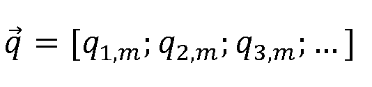
the greatest reduction of the cost function. When the best candidate variation has been identified, the new operating point becomes
 and the algorithm is carried out anew.
[0073] The control unit dispatches instructions to the VSIs of the network, which causes them to adjust the targets in accordance with which they modify the voltage of each harmonic m they detect. In each iteration of the algorithm, the control unit transmits the variations AqJ m of the power coefficients that have to be applied by the VSIs that are addressed (step 1206). Specifically, each VSIj listens to the messages from the master VSI (or the standalone control unit) and reads the value AqJ m that is intended for it (step 1207). It is worthwhile noting that, at a given time, the variation AqJ m may be zero for many VSIs. In this case, the control unit does not need to address those VSIs at that time.
[0074] Upon receipt of an instruction to apply AqJiTn, the VSIj addressed applies a setpoint variation of the voltage of harmonic m (step S1208):
where

uVSIjm being the voltage that VSIj had to apply to steer the voltage of harmonic m to
U qSetpOrdn-
[0075] As the change of the setpoint in a single VSI may result in a different distribution of the compensation power over the entire network, all VSIs communicate their individual compensation powers to the control unit (S1201 ) after each application of a change of the operating point.
[0076] The algorithm could be started from any initial operating point q. Preferably, however, it is started at meaning that each VSI tries to drive the

amplitudes of the harmonics voltages to 0 If a VSI is added

to the network or if a VSI becomes operational again after an interruption, it also preferably starts with

[0077] Fig. 13 shows the convergence path of a simplified optimisation algorithm for a simulated network of VSIs. Only two VSIs have been actively controlled by the control unit, the other ones were left running at their nominal compensation power. The reason for this simplification is that the path becomes three-dimensional with three centrally controlled VSIs, four-dimensional with four centrally controlled VSIs, etc., making it difficult to visualise such a path. Fig. 13 shows the isolines of the cost function. In the illustrated case, the cost function was known globally (i.e. for all theoretically possible operating points), since all relevant parameters were entered into the simulation. In a real situation, the cost function is not globally known and, furthermore, may change over time. Fig. 13 shows that the operating point of the network roughly follows the steepest descent to the minimum of the cost function (around

[0078] Fig. 14 illustrates that, at each operating point, the algorithm tests different candidate variations among which it selects the one that results in
 the steepest descending slope (see also step 1203 in Fig. 12). The slope is calculated as:

[0079] In the example, it is assumed that may take three values: -


and 20%, preferably between 5% and 10%). In this case, the value of Aqmax is kept constant. In more elaborate versions of the algorithm, may be able to vary over

time and/or may take different values for different VSIs. For each operating point, that makes eight candidate variations (Δξ = [0; 0] is no variation) that the control unit tests one by one. To this end, the control unit sends the corresponding candidate instructions to the VSIs of the network and reads the returned compensation powers. The first slope resulting from the first candidate variation applied at a given operating point, the candidate operating point and the obtained total compensating power are stored in respective memories (alternatively, this is done only if the obtained slope is negative). The control unit then instructs the VSIs to apply the second candidate variation Δξ and compares the obtained slope of the cost function with the first slope. If the new slope is a steeper descent than the previously stored slope (tested at step S1203 in Fig. 12) the new slope, the new operating point and the new total compensation power take the place of the previously stored values. These steps are carried out analogously for all candidate variations. When the algorithm has cycled across all allowed variations, the surviving candidate operating point is the one implying the steepest descent.
[0080] Before testing the candidate instructions at an operating point, the control unit determines a ranking of the VSIs in accordance with the apparent power they supply to the grid for the given harmonic m. The algorithm gives precedence to variations of the power coefficient of the VSI providing the highest compensation power, i.e. the closest to the non-linear loads, because that power coefficient has the greatest impact on the total compensation power in comparison to the power coefficients of the other VSIs. [0081 ] Fig. 15 illustrates a variant of the algorithm of Figs. 13 and 14, which differs from that algorithm described above in that a new operation point is selected as soon as a candidate operating point is found for which the global apparent power is lower,
and not only after having tested all the available candidate operating. The algorithm converges on different paths if the optimisation algorithm gives a higher priority to the variation of the power coefficient of VSh, the VSI closest to the non-linear load (graph on the left), or to the power coefficient of VSIj, the VSI more distant from the non-linear load (graph on the right). In that variant of the algorithm, the path thus depends on the order of testing the VSIs.
[0082] Fig. 16 illustrates what happens if one of the centrally controlled VSIs is not capable of providing the full compensation power: the optimisation algorithm routes the remaining VSI towards another operating point. When all VSIs are fully operational again, the algorithm converges to the optimal operating point. On the left graph of Fig. 16, VSh is running at limited compensation power (qi,m < 80%), which causes the control unit to run VSb with increasing q2,m. When VSh is no longer limited in compensation power, its power coefficient is increased by the control unit. At the same time, the power coefficient q2,m of VSb is decreased, so that the algorithm converges towards the optimal operating point known from Figs. 13 and 15. The right graph of Fig. 16 shows the same scenario with the roles of VSh and VSb inverted.
[0083] Fig. 17 schematically illustrates a possible embodiment of a (slave) VSI 10 for converting a DC source current into alternating current. The VSI 10 comprises a harmonics compensator 12 configured to detect one or more harmonics of the fundamental frequency of the electrical supply grid and to control the alternating current(s) to be injected into the electrical supply grid in such a way as to selectively drive the voltage amplitude of the harmonics towards respective setpoints. The VSI 10 further comprises a communications module 14, which allows the VSI 10 to join the network of VSIs. The harmonics compensator 12 is connected to the communications module to send the currently measured complex compensation power over the network and to adjust its setpoints for the different harmonics depending on instructions and communicated to it by a control unit.
[0084] Fig. 18 schematically shows a (master) VSI 20 with an integrated control unit 22 for controlling the network of VSIs. The control unit 22 is comprised of a communications module 24 and a microcontroller 26. The microcontroller 26 is connected to the communication interface and evaluates a cost or profit function using the operating parameters received from the slave VSIs. The microcontroller 26 further
dispatches the instructions to the slave VSIs, which causes them to adjust their power coefficients and thereby provoke variations of the cost or profit function.
[0085] Figs. 19 and 20 show the structures of preferred embodiments of the harmonics compensators 12 (Fig. 17) and 28 (Fig. 18) in more detail. Fig. 19 shows a VSI adapted for a 3-phase grid whereas Fig. 20 shows a VSI adapted for a single- phase grid.
[0086] The harmonics compensators of Figs. 19 and 20 use finite impulse response (FIR) filters to separate the fundamental oscillation and the individual harmonics. It should be noted, however, that other filter types could be used as well. Each harmonic is compensated using a dedicated, phase-locked-loop (PLL) based compensation path.
[0087] The voltage magnitude and frequency setpoints are equal to the utility grid voltage magnitude and frequency in grid-tied mode or fixed to a given value in standalone mode or is provided by a droopl static (e.g. frequency vs. inverter active power P produced and voltage magnitude vs. inverter reactive power Q exchanged).
[0088] Turning now to Fig. 19, relating to the case of a 3-phase power network, a pulse width modulator (PWM) 30 get as input values the voltages ui , U2, U3 to be generated. The firing signals from the PWM 30 feed a basic voltage source inverter circuit 32, which is supplied with a DC supply voltage UDC The three-phase output of the circuit 32 is fed through a passive filter network 34 to the primary side of a power transformer 36. The secondary side of the power transformer 36 is connected through an electric power supply network to an electrical load 38 and a utility grid 40.
[0089] The three power supply phases U2act and U3act are detected by sensors

42 and are fed into the compensation paths. The feedback network provides a signal path 5001 dedicated to the fundamental frequency, as well as, parallel thereto, further signal paths 5005, 5007, 501 1 , 5013, 5017, 50_n, each of which is adapted and dedicated to a specific harmonic frequency. Each signal path comprises a frequency filter 44 adapted to the respective frequency. Each filter path further comprises a frequency detector 46 adapted to the respective frequency. Moreover, each filter path comprises a controller 48 producing output variables that reduce the error between the signals entered as the process variables and the setpoints.
[0090] Each filter 44 receives the three power supply phases U3act, filters

them for the respective fundamental or harmonic frequency, and provides three filtered output signals u i FiRm, U2FiRm, U3FiRm, where m is 1 for the fundamental or 5, 7, 1 1 , etc. for the harmonics. [0091 ] Each frequency detector 46 comprises a PLL, adapted and dedicated to the respective frequency. Each PLL receives the FIR filter outputs U i FiRm, U2FiRm, U3FiRm and a respective frequency setpoint (fsetpordm) as inputs. The outputs Udordm, uqordm of each frequency detector 46 correspond to the direct and quadrature components of the voltage at the respective frequency. [0092] Each controller 48 comprises a PI controller. Each PI controller is adapted and dedicated to the respective frequency. Each PI controller receives the outputs of the corresponding frequency detector 46 and a voltage setpoint (defined by the direct component setpoint Udsetpordm and the quadrature component setpoint uqsetPordm in the Park coordinates system). In response to the signals received, each PI controller outputs voltages Udctrioutordm and uqctrioutordm corresponding to the direct and quadrature components of the compensation output voltage in the Park coordinates system. Since each PLL controller inherently transforms the input voltages into a reference frame synchronized with the utility frequency, both a PARK inverse function 52 and a CLARK inverse function 54 are provided to transform the PI controller output back into three sinusoidal signals u i ordm, U20rdm, U30rdm spaced by 1 20° (with respect to the fundamental frequency).
[0093] The output signals u i ordm, U20rdm, U30rdm are fed into respective summing networks, which compute

respectively. The resulting voltages ui , U2 and U3 are fed into the PWM 30. [0094] Fig. 20 relates to the case of a 1 -phase power network or grid. In this case, the 3RD harmonic needs to be compensated. A pulse width modulator (PWM) 60 gets as input value the voltage u to be generated. The firing signals produced by the PWM 60 feed a single-phase voltage source inverter circuit 62, which is supplied with a supply voltage UDC The single-phase output of circuit 62 is fed through a passive filter network 64 to the primary side of a power transformer 66. The secondary side of the power transformer 66 is connected through an electric power supply network to an electrical load 68 and a utility grid 70.
[0095] The power supply phase uact is detected by sensor 72 and is fed into the compensation paths. The feedback network provides a signal path 8001 dedicated to the fundamental frequency, as well as, parallel thereto, further signal paths 8003, 8005,... 80_m, each of which is adapted and dedicated to a specific harmonic frequency. Each signal path comprises a frequency filter 74 adapted to the respective frequency. Each filter path further comprises a frequency detector 76 adapted to the respective frequency. Moreover, each filter path comprises a controller 78 producing output variables that reduce the error between the signals entered as the process variables and the setpoints. [0096] Each filter 74 filters the single phase power supply voltage
 so as to extract the respective fundamental or harmonic frequency, and provides a filtered output signal UFiRk, where k is 1 for the fundamental or 3, 5, 7, etc. for the harmonics.
[0097] Each frequency detector 76 comprises a PLL, adapted and dedicated to the respective frequency. Each PLL receives the FIR filter outputs UFiRk and a respective frequency setpoint (fsetpordk) as inputs. The outputs Udordk, uqordk of each frequency detector 76 correspond to the direct and quadrature components of the voltage at the respective frequency.
[0098] Each controller 78 comprises a PI controller adapted and dedicated to the respective frequency. Each PI controller receives the outputs of the corresponding frequency detector 76 and a voltage setpoint (defined by the direct component setpoint Udsetpordk and the quadrature component setpoint uqsetPordk). In response to the signals received, each PI controller outputs voltages Udctrioutordk and uqctrioutordk corresponding to the direct and quadrature components of the compensation output voltage. Since each PLL controller inherently transforms the input voltages into a reference frame synchronized with the utility frequency, a Polar-to-Cartesian transformation 82 is provided to transform the PI controller output into a sinusoidal signal uordk. Udctrioutordk and Uqctrioutordk are the two components of the voltage vector in a coordinates system rotated by angle pordk. The voltage vector is thus represented through its polar coordinates, i e
and its angle

returns the sine and cosine components in the fixed coordinates system, of which the sine component is the 1 -phase sinusoidal wave that is sent to the PWM.
[0099] The output signals uordk are fed into a summing network, which computes u = ∑k uordk - The resulting voltage u is fed into the PWM 60.
[0100] Fig. 21 illustrates a power network, wherein the VSIs are organised in zones. In each zone, the VSIs form a cluster with one central control unit (or one master VSI). In case of need, the VSIs of one zone can contribute to the harmonics compensation of another zone, for instance, when the VSI's of that zone do not have enough power available to compensate all the harmonics. A zone of VSIs may be defined by a given maximum distance of the VSIs to each other. The total compensation power in one zone is the sum of all the compensation powers provided by the VSIs of that zone. [0101 ] Every VSI communicates its currently produced compensation power to the master VSI or to the control unit, which calculates the total compensation power, ranks the VSIs in accordance with their compensation powers, determines the variations of the power coefficients and sends the corresponding instructions to the VSIs of its zone.
[0102] It should be noted that the VSIs may be configured to be able to take both the role of the master VSI and the role of the slave VSI. In that case, a conflict resolution algorithm may be used to establish that there is only one master VSI per cluster or zone. All but one VSI equipped for acting as the control unit are then switched into slave mode. If the current master VSI fails (stops working or stops communicating), one of the remaining VSIs with master capability may take over the master tasks. Again, the conflict resolution algorithm may be used to determine which one of the remaining VSIs becomes the master.
[0103] According to a preferred embodiment of the control unit, if one or several VSIs operate in limited power mode ( qUm < 1), e.g. for lack of available primary energy, the optimisation algorithm may set their power coefficients sequentially to a still lower level in order to determine their contribution in the total compensation power balance. If the total compensation power becomes worse, the optimisation algorithm sets the related power coefficient to its original value.
[0104] While specific embodiments have been described herein in detail, those skilled in the art will appreciate that various modifications and alternatives to those details could be developed in light of the overall teachings of the disclosure. Accordingly, the particular arrangements disclosed are meant to be illustrative only and not limiting as
to the scope of the invention, which is to be given the full breadth of the appended claims and any and all equivalents thereof.
Claims
1 . A power inverter for converting one or more source currents or voltages into one or more alternating currents or voltages to be injected into an electrical supply grid, the power inverter comprising
a harmonics compensator configured to detect one or more harmonics of the fundamental frequency of the electrical supply grid and to control the one or more alternating currents or voltages to be injected into the electrical supply grid in such a way as to selectively modify the voltage of at least one of the one or more detected harmonics in accordance with one or more respective targets;
characterised in that
the power inverter comprises a communication interface to join a network of power inverters;
and in that the harmonics compensator is connected to the communication interface and configured to share operating parameters over the network, the operating parameters comprising the powers the power inverter delivers to the electrical supply grid at each of the one or more harmonics, and to adjust the one or more targets depending on instructions and/or operating parameters communicated to it via the network.
2. The power inverter as claimed in claim 1 , wherein the harmonics compensator comprises a plurality of harmonics control loops, each harmonics control loop being configured to control the voltage of a specific harmonic.
3. The power inverter as claimed in claim 2, wherein the one or more targets are the setpoints of the harmonics control loops.
4. A control unit for controlling a network of power inverters as claimed in any one of claims 1 to 3, comprising
a communication interface for communicating with the power inverters of the network and for receiving operating parameters of the power inverters shared by them over the network, the operating parameters comprising the powers each power inverter delivers to the electrical supply grid at each of the one or more harmonics;
a processor connected to the communication interface, the processor being configured to evaluate an objective function using the received operating parameters, the objective function reflecting the total apparent power delivered
by the power inverters at each one of the one or more harmonics, respectively, and to dispatch instructions to power inverters of the network to provoke variations of the objective function, the instructions causing the power inverters of the network to adjust the one or more targets in accordance with which they modify the voltage of at least one of the one or more harmonics they detect, wherein the processor is configured to generate the instructions in accordance with an optimisation algorithm minimizing the total apparent power delivered by the power inverters at each one of the one or more harmonics, respectively.
5. The control unit as claimed in claim 4, wherein the processor is configured to generate the instructions in accordance with an optimisation algorithm concerning the objective function.
6. The control unit as claimed in claim 5, wherein the targets of the power inverters of the network define an operational state of the network, and wherein the processor is configured to dispatch candidate instructions in an iterative manner to detect a variation of a current operational state that implies an improvement in terms of the objective function and to update the current operational state when such a variation is detected.
7. The control unit as claimed claim 5 or 6, wherein the processor is configured to evaluate the objective function separately for each harmonic and to optimise the objective function for each harmonic.
8. The control unit as claimed in any one of claims 6 to 7, wherein the processor is configured to maintain, for each harmonic, a schedule defining an order according to which the processor dispatches candidate instructions to the power inverters of the network, the processor being further configured to modify the schedule depending on the operating parameters shared by the power inverters.
9. The control unit as claimed in any one of claims 4 to 1 1 , wherein the processor is configured to maintain, for each harmonic, a ranking of the power inverters of the network in accordance with the electric power delivered by the power inverters at that harmonic, the processor being configured, for each harmonic, to dispatch candidate instructions more frequently to power inverters with a higher ranking than to power inverters with a lower ranking.
10. A power inverter as claimed in any one of claims 1 to 3, comprising a control unit as claimed in any one of claims 4 to 9.
1 1 . The power inverter as claimed in claim 10, wherein the control unit is configured to be placed into a master mode, in which the processor evaluates the objective function and dispatches instructions to power inverters of the network, and into a slave mode, in which the processor does not dispatch instructions to power inverters of the network.
12. A network of power inverters, comprising:
a plurality of power inverters as claimed in any one of claims 1 to 3, and at least one control unit as claimed in any one of claims 4 to 9 or at least one power inverter as claimed in claim 10 or 1 1 .
Priority Applications (1)
| Application Number | Priority Date | Filing Date | Title |
|---|---|---|---|
| EP16730350.2A EP3311459B1 (en) | 2015-06-16 | 2016-06-15 | Power inverter, control unit for power inverters and network of power inverters |
Applications Claiming Priority (2)
| Application Number | Priority Date | Filing Date | Title |
|---|---|---|---|
| LU92743A LU92743B1 (en) | 2015-06-16 | 2015-06-16 | Power inverter, control unit for power inverters and network of power inverters |
| LU92743 | 2015-06-16 |
Publications (1)
| Publication Number | Publication Date |
|---|---|
| WO2016202859A1 true WO2016202859A1 (en) | 2016-12-22 |
Family
ID=53490220
Family Applications (1)
| Application Number | Title | Priority Date | Filing Date |
|---|---|---|---|
| PCT/EP2016/063759 Ceased WO2016202859A1 (en) | 2015-06-16 | 2016-06-15 | Power inverter, control unit for power inverters and network of power inverters |
Country Status (3)
| Country | Link |
|---|---|
| EP (1) | EP3311459B1 (en) |
| LU (1) | LU92743B1 (en) |
| WO (1) | WO2016202859A1 (en) |
Cited By (7)
| Publication number | Priority date | Publication date | Assignee | Title |
|---|---|---|---|---|
| WO2018142543A1 (en) * | 2017-02-02 | 2018-08-09 | 三菱電機株式会社 | Higher harmonic suppression device and higher harmonic suppression system |
| RU188573U1 (en) * | 2018-12-29 | 2019-04-17 | федеральное государственное бюджетное образовательное учреждение высшего образования "Национальный исследовательский университет "МЭИ" (ФГБОУ ВО "НИУ "МЭИ") | Multifunctional power quality regulator for three-phase 0.4 kV power distribution systems |
| WO2019145376A1 (en) * | 2018-01-25 | 2019-08-01 | Universite Du Luxembourg | Grid conductance and susceptance estimation for power control in grid-tied inverters |
| CN110677023A (en) * | 2018-07-02 | 2020-01-10 | 帕洛阿尔托研究中心公司 | Coordinated power converter for improved efficiency and power electronics lifetime |
| CN113098065A (en) * | 2021-04-15 | 2021-07-09 | 东北电力大学 | Model order reduction method suitable for droop grid-connected inverter network |
| CN114243704A (en) * | 2021-12-16 | 2022-03-25 | 国网冀北电力有限公司秦皇岛供电公司 | Method, device, terminal and storage medium for optimizing harmonic waves of power distribution network |
| CN116599125A (en) * | 2023-05-04 | 2023-08-15 | 国网江苏省电力有限公司电力科学研究院 | A new energy station simulation optimization method, device, equipment and storage medium |
Families Citing this family (1)
| Publication number | Priority date | Publication date | Assignee | Title |
|---|---|---|---|---|
| CN119627875B (en) * | 2024-11-22 | 2026-01-06 | 山东大学 | A method and system for evaluating time-varying harmonic propagation relationships in power distribution systems |
Citations (10)
| Publication number | Priority date | Publication date | Assignee | Title |
|---|---|---|---|---|
| US5648894A (en) | 1994-09-30 | 1997-07-15 | General Electric Company | Active filter control |
| WO1997049168A1 (en) | 1996-06-21 | 1997-12-24 | Wisconsin Alumni Research Foundation | Power line harmonic reduction by hybrid parallel active/passive filter system with square wave inverter and dc bus control |
| DE19819869A1 (en) | 1998-04-27 | 1999-10-28 | Ruediger Bredtmann | Harmonics compensation method in electric supply network |
| DE10032447A1 (en) | 2000-07-04 | 2002-01-17 | Fahrzeugausruestung Berlin Gmb | Current harmonic compensation method for pulsed network current regulator uses software analysis of network input current for control of compensation regulators |
| WO2002041463A2 (en) | 2000-11-17 | 2002-05-23 | Edp S.R.L. | System for correcting power factor and harmonics present on an electroduct in an active way and with high-dynamics |
| EP0965159B1 (en) | 1997-03-13 | 2004-08-11 | Asea Brown Boveri Jumet S.A. | An active filter device |
| EP1079493B1 (en) | 1999-08-23 | 2008-10-29 | Eltroplan-Revcon Elektrotechnische Anlagen GmbH | Method for harmonics compensation in electric power networks |
| EP2065994A2 (en) * | 2007-11-28 | 2009-06-03 | ABB Oy | Compensation of harmonics of electrical network |
| WO2011032287A1 (en) | 2009-09-18 | 2011-03-24 | Queen's University At Kingston | Distributed power generation interface |
| EP2437383A2 (en) | 2010-10-04 | 2012-04-04 | Liebherr-Elektronik GmbH | Modules for active mains filter and active mains filter |
-
2015
- 2015-06-16 LU LU92743A patent/LU92743B1/en active
-
2016
- 2016-06-15 WO PCT/EP2016/063759 patent/WO2016202859A1/en not_active Ceased
- 2016-06-15 EP EP16730350.2A patent/EP3311459B1/en active Active
Patent Citations (10)
| Publication number | Priority date | Publication date | Assignee | Title |
|---|---|---|---|---|
| US5648894A (en) | 1994-09-30 | 1997-07-15 | General Electric Company | Active filter control |
| WO1997049168A1 (en) | 1996-06-21 | 1997-12-24 | Wisconsin Alumni Research Foundation | Power line harmonic reduction by hybrid parallel active/passive filter system with square wave inverter and dc bus control |
| EP0965159B1 (en) | 1997-03-13 | 2004-08-11 | Asea Brown Boveri Jumet S.A. | An active filter device |
| DE19819869A1 (en) | 1998-04-27 | 1999-10-28 | Ruediger Bredtmann | Harmonics compensation method in electric supply network |
| EP1079493B1 (en) | 1999-08-23 | 2008-10-29 | Eltroplan-Revcon Elektrotechnische Anlagen GmbH | Method for harmonics compensation in electric power networks |
| DE10032447A1 (en) | 2000-07-04 | 2002-01-17 | Fahrzeugausruestung Berlin Gmb | Current harmonic compensation method for pulsed network current regulator uses software analysis of network input current for control of compensation regulators |
| WO2002041463A2 (en) | 2000-11-17 | 2002-05-23 | Edp S.R.L. | System for correcting power factor and harmonics present on an electroduct in an active way and with high-dynamics |
| EP2065994A2 (en) * | 2007-11-28 | 2009-06-03 | ABB Oy | Compensation of harmonics of electrical network |
| WO2011032287A1 (en) | 2009-09-18 | 2011-03-24 | Queen's University At Kingston | Distributed power generation interface |
| EP2437383A2 (en) | 2010-10-04 | 2012-04-04 | Liebherr-Elektronik GmbH | Modules for active mains filter and active mains filter |
Non-Patent Citations (10)
| Title |
|---|
| A. PRASAD; P. ZOGIAS; S. MANIAS: "An Active Power Factor Compensation Correction Technique for Three-Phase Diode Rectifiers", IEEE TRANSACTIONS ON POWER ELECTRONICS, vol. 6, no. 1, January 1991 (1991-01-01) |
| A. SALAMAH; S. FINNEY; B. WILLIAMS: "Three-phase phase-lock loop for distorted utilities", IET ELECTRICAL POWER APPLICATIONS, vol. 1, no. 6, 2007, pages 937 - 945, XP006029738 |
| B. REN; Y. ZHONG; X. SUN; X. TONG: "A Digital PLL Control Method Based on the FIR Filter for a Grid-Connected Single-Phase Power Conversion System", IEEE |
| C. MARQUES; M. RIBEIRO; C. DUQUE; P. RIBEIRO; E. DA SILVA: "A Controlled Filtering Method for Estimating Harmonics of Off-Nominal Frequencies", IEEE TRANSACTIONS ON SMART GRID, vol. 3, no. 1, March 2012 (2012-03-01), XP011422598, DOI: doi:10.1109/TSG.2011.2174259 |
| CALDOGNETTO TOMMASO ET AL: "Improving Microgrid Performance by Cooperative Control of Distributed Energy Sources", IEEE TRANSACTIONS ON INDUSTRY APPLICATIONS, IEEE SERVICE CENTER, PISCATAWAY, NJ, US, vol. 50, no. 6, November 2014 (2014-11-01), pages 3921 - 3930, XP011564535, ISSN: 0093-9994, [retrieved on 20141118], DOI: 10.1109/TIA.2014.2313648 * |
| D. YAZDANI, IEEE TRANSACTIONS ON POWER ELECTRONICS, vol. 25, 4 January 2010 (2010-01-04) |
| F. WANG; M BENHABIB; J. DUARTE; M. HENDRIX: "High Performance Stationary Frame Filters for Symmetrical Sequences or Harmonics Separation under a Variety of Grid Conditions", IEEE |
| JINTAKOSONWIT P ET AL: "Implementation and performance of cooperative control of shunt active filters for harmonic damping throughout a power distribution system", CONFERENCE RECORD OF THE 2002 IEEE INDUSTRY APPLICATIONS CONFERENCE : 37TH IAS ANNUAL MEETING ; 13 - 18 OCTOBER 2002, PITTSBURGH, PENNSYLVANIA, USA; [CONFERENCE RECORD OF THE IEEE INDUSTRY APPLICATIONS CONFERENCE. IAS ANNUAL MEETING], IEEE SERVICE CE, 13 October 2002 (2002-10-13), pages 51 - 58vol.1, XP032143410, ISBN: 978-0-7803-7420-1, DOI: 10.1109/IAS.2002.1044066 * |
| KENNEDY K ET AL: "Development of a Network-Wide Harmonic Control Scheme Using an Active Filter", IEEE TRANSACTIONS ON POWER DELIVERY, IEEE SERVICE CENTER, NEW YORK, NY, US, vol. 10, no. 3, July 2007 (2007-07-01), pages 1847 - 1856, XP011186587, ISSN: 0885-8977 * |
| L. MORAN, IEEE TRANSACTIONS ON INDUSTRIAL ELECTRONICS, vol. 42, no. 4, August 1995 (1995-08-01) |
Cited By (18)
| Publication number | Priority date | Publication date | Assignee | Title |
|---|---|---|---|---|
| US20200067399A1 (en) * | 2017-02-02 | 2020-02-27 | Mitsubishi Electric Corporation | Harmonic suppression device and harmonic suppression system |
| CN110249492B (en) * | 2017-02-02 | 2023-08-11 | 三菱电机株式会社 | Harmonic suppression device and harmonic suppression system |
| KR20190084113A (en) * | 2017-02-02 | 2019-07-15 | 미쓰비시덴키 가부시키가이샤 | Harmonic suppression and harmonic suppression systems |
| US10992218B2 (en) | 2017-02-02 | 2021-04-27 | Mitsubishi Electric Corporation | Harmonic suppression device and harmonic suppression system |
| WO2018142543A1 (en) * | 2017-02-02 | 2018-08-09 | 三菱電機株式会社 | Higher harmonic suppression device and higher harmonic suppression system |
| CN110249492A (en) * | 2017-02-02 | 2019-09-17 | 三菱电机株式会社 | Limitation of high harmonics device and limitation of high harmonics system |
| KR102233824B1 (en) * | 2017-02-02 | 2021-03-30 | 미쓰비시덴키 가부시키가이샤 | Harmonic suppression device and harmonic suppression system |
| EP3579367A4 (en) * | 2017-02-02 | 2020-02-12 | Mitsubishi Electric Corporation | SUPERIOR HARMONIC SUPPRESSION DEVICE AND SUPERIOR HARMONIC SUPPRESSION SYSTEM |
| LU100681B1 (en) * | 2018-01-25 | 2019-08-21 | Univ Luxembourg | Grid conductance and susceptance estimation for power control in grid-tied inverters |
| WO2019145376A1 (en) * | 2018-01-25 | 2019-08-01 | Universite Du Luxembourg | Grid conductance and susceptance estimation for power control in grid-tied inverters |
| CN110677023A (en) * | 2018-07-02 | 2020-01-10 | 帕洛阿尔托研究中心公司 | Coordinated power converter for improved efficiency and power electronics lifetime |
| CN110677023B (en) * | 2018-07-02 | 2022-08-12 | 帕洛阿尔托研究中心公司 | Harmonized Power Converters for Increased Efficiency and Lifetime of Power Electronics |
| RU188573U1 (en) * | 2018-12-29 | 2019-04-17 | федеральное государственное бюджетное образовательное учреждение высшего образования "Национальный исследовательский университет "МЭИ" (ФГБОУ ВО "НИУ "МЭИ") | Multifunctional power quality regulator for three-phase 0.4 kV power distribution systems |
| CN113098065A (en) * | 2021-04-15 | 2021-07-09 | 东北电力大学 | Model order reduction method suitable for droop grid-connected inverter network |
| CN114243704A (en) * | 2021-12-16 | 2022-03-25 | 国网冀北电力有限公司秦皇岛供电公司 | Method, device, terminal and storage medium for optimizing harmonic waves of power distribution network |
| CN114243704B (en) * | 2021-12-16 | 2023-08-18 | 国网冀北电力有限公司秦皇岛供电公司 | Method, device, terminal and storage medium for optimizing distribution network harmonics |
| CN116599125A (en) * | 2023-05-04 | 2023-08-15 | 国网江苏省电力有限公司电力科学研究院 | A new energy station simulation optimization method, device, equipment and storage medium |
| CN116599125B (en) * | 2023-05-04 | 2023-11-24 | 国网江苏省电力有限公司电力科学研究院 | A new energy station simulation optimization method, device, equipment and storage medium |
Also Published As
| Publication number | Publication date |
|---|---|
| LU92743B1 (en) | 2016-12-19 |
| EP3311459B1 (en) | 2019-08-07 |
| EP3311459A1 (en) | 2018-04-25 |
Similar Documents
| Publication | Publication Date | Title |
|---|---|---|
| EP3311459B1 (en) | Power inverter, control unit for power inverters and network of power inverters | |
| Shafiee et al. | A multi-functional fully distributed control framework for AC microgrids | |
| Vasquez et al. | Hierarchical control of intelligent microgrids | |
| Peyghami et al. | Decentralized load sharing in a low-voltage direct current microgrid with an adaptive droop approach based on a superimposed frequency | |
| Han et al. | Review of active and reactive power sharing strategies in hierarchical controlled microgrids | |
| Micallef et al. | Secondary control for reactive power sharing and voltage amplitude restoration in droop-controlled islanded microgrids | |
| Micallef et al. | Secondary control for reactive power sharing in droop-controlled islanded microgrids | |
| KR101689315B1 (en) | System and method for controlling in multi-frequency microgrid | |
| US20180233911A1 (en) | Electrical Power Transmission | |
| JP2017200409A (en) | Controller and power conversion system | |
| Sadeque et al. | On control schemes for grid-forming inverters | |
| Alwaz et al. | Harmonic power sharing and power quality improvement of droop controller based low voltage islanded microgrid | |
| JP6276370B2 (en) | Hybrid power supply | |
| US10014690B2 (en) | Double-stage inverter apparatus for energy conversion systems and control method thereof | |
| KR20200008314A (en) | Distributed power system of microgrid | |
| KR20170035935A (en) | A voltage source converter | |
| Hoang et al. | Adaptive virtual impedance control scheme to eliminate reactive power sharing errors in islanded microgrid | |
| Mirzaeva et al. | Decentralised control of parallel inverters in an ac microgrid using downstream current as an implicit communication method | |
| Camacho et al. | Control strategies based on effective power factor for distributed generation power plants during unbalanced grid voltage | |
| RU2381607C1 (en) | Method to synchronise controlled static source of variable voltage and variable voltage source and switching them into parallel operation | |
| Madhumitha et al. | Voltage regulation in mircogrid using adaptive controller | |
| Efika et al. | Reactive power compensation by modular multilevel flying capacitor converter-based STATCOM using PS-PWM | |
| Ahmed et al. | Autonomous adaptive sensorless controller of inverter-based islanded-distributed generation system | |
| US20180323726A1 (en) | Initializing virtual oscillator control | |
| Li et al. | An Adaptive active power optimal allocation strategy for power loss minimization in islanded microgrids |
Legal Events
| Date | Code | Title | Description |
|---|---|---|---|
| 121 | Ep: the epo has been informed by wipo that ep was designated in this application |
Ref document number: 16730350 Country of ref document: EP Kind code of ref document: A1 |
|
| NENP | Non-entry into the national phase |
Ref country code: DE |
|
| WWE | Wipo information: entry into national phase |
Ref document number: 2016730350 Country of ref document: EP |