WO2016199202A1 - Sensor apparatus - Google Patents
Sensor apparatus Download PDFInfo
- Publication number
- WO2016199202A1 WO2016199202A1 PCT/JP2015/066514 JP2015066514W WO2016199202A1 WO 2016199202 A1 WO2016199202 A1 WO 2016199202A1 JP 2015066514 W JP2015066514 W JP 2015066514W WO 2016199202 A1 WO2016199202 A1 WO 2016199202A1
- Authority
- WO
- WIPO (PCT)
- Prior art keywords
- cross
- signal
- transmission
- antenna
- correlation processing
- Prior art date
Links
Images


Classifications
-
- G—PHYSICS
- G01—MEASURING; TESTING
- G01S—RADIO DIRECTION-FINDING; RADIO NAVIGATION; DETERMINING DISTANCE OR VELOCITY BY USE OF RADIO WAVES; LOCATING OR PRESENCE-DETECTING BY USE OF THE REFLECTION OR RERADIATION OF RADIO WAVES; ANALOGOUS ARRANGEMENTS USING OTHER WAVES
- G01S7/00—Details of systems according to groups G01S13/00, G01S15/00, G01S17/00
- G01S7/02—Details of systems according to groups G01S13/00, G01S15/00, G01S17/00 of systems according to group G01S13/00
- G01S7/40—Means for monitoring or calibrating
- G01S7/4052—Means for monitoring or calibrating by simulation of echoes
-
- H—ELECTRICITY
- H01—ELECTRIC ELEMENTS
- H01Q—ANTENNAS, i.e. RADIO AERIALS
- H01Q3/00—Arrangements for changing or varying the orientation or the shape of the directional pattern of the waves radiated from an antenna or antenna system
- H01Q3/26—Arrangements for changing or varying the orientation or the shape of the directional pattern of the waves radiated from an antenna or antenna system varying the relative phase or relative amplitude of energisation between two or more active radiating elements; varying the distribution of energy across a radiating aperture
-
- G—PHYSICS
- G01—MEASURING; TESTING
- G01S—RADIO DIRECTION-FINDING; RADIO NAVIGATION; DETERMINING DISTANCE OR VELOCITY BY USE OF RADIO WAVES; LOCATING OR PRESENCE-DETECTING BY USE OF THE REFLECTION OR RERADIATION OF RADIO WAVES; ANALOGOUS ARRANGEMENTS USING OTHER WAVES
- G01S13/00—Systems using the reflection or reradiation of radio waves, e.g. radar systems; Analogous systems using reflection or reradiation of waves whose nature or wavelength is irrelevant or unspecified
- G01S13/02—Systems using reflection of radio waves, e.g. primary radar systems; Analogous systems
- G01S13/06—Systems determining position data of a target
- G01S13/08—Systems for measuring distance only
- G01S13/32—Systems for measuring distance only using transmission of continuous waves, whether amplitude-, frequency-, or phase-modulated, or unmodulated
- G01S13/325—Systems for measuring distance only using transmission of continuous waves, whether amplitude-, frequency-, or phase-modulated, or unmodulated using transmission of coded signals, e.g. P.S.K. signals
-
- G—PHYSICS
- G01—MEASURING; TESTING
- G01S—RADIO DIRECTION-FINDING; RADIO NAVIGATION; DETERMINING DISTANCE OR VELOCITY BY USE OF RADIO WAVES; LOCATING OR PRESENCE-DETECTING BY USE OF THE REFLECTION OR RERADIATION OF RADIO WAVES; ANALOGOUS ARRANGEMENTS USING OTHER WAVES
- G01S13/00—Systems using the reflection or reradiation of radio waves, e.g. radar systems; Analogous systems using reflection or reradiation of waves whose nature or wavelength is irrelevant or unspecified
- G01S13/02—Systems using reflection of radio waves, e.g. primary radar systems; Analogous systems
- G01S13/06—Systems determining position data of a target
- G01S13/08—Systems for measuring distance only
- G01S13/32—Systems for measuring distance only using transmission of continuous waves, whether amplitude-, frequency-, or phase-modulated, or unmodulated
- G01S13/34—Systems for measuring distance only using transmission of continuous waves, whether amplitude-, frequency-, or phase-modulated, or unmodulated using transmission of continuous, frequency-modulated waves while heterodyning the received signal, or a signal derived therefrom, with a locally-generated signal related to the contemporaneously transmitted signal
- G01S13/347—Systems for measuring distance only using transmission of continuous waves, whether amplitude-, frequency-, or phase-modulated, or unmodulated using transmission of continuous, frequency-modulated waves while heterodyning the received signal, or a signal derived therefrom, with a locally-generated signal related to the contemporaneously transmitted signal using more than one modulation frequency
-
- G—PHYSICS
- G01—MEASURING; TESTING
- G01S—RADIO DIRECTION-FINDING; RADIO NAVIGATION; DETERMINING DISTANCE OR VELOCITY BY USE OF RADIO WAVES; LOCATING OR PRESENCE-DETECTING BY USE OF THE REFLECTION OR RERADIATION OF RADIO WAVES; ANALOGOUS ARRANGEMENTS USING OTHER WAVES
- G01S13/00—Systems using the reflection or reradiation of radio waves, e.g. radar systems; Analogous systems using reflection or reradiation of waves whose nature or wavelength is irrelevant or unspecified
- G01S13/02—Systems using reflection of radio waves, e.g. primary radar systems; Analogous systems
- G01S13/06—Systems determining position data of a target
- G01S13/42—Simultaneous measurement of distance and other co-ordinates
-
- H—ELECTRICITY
- H01—ELECTRIC ELEMENTS
- H01Q—ANTENNAS, i.e. RADIO AERIALS
- H01Q21/00—Antenna arrays or systems
- H01Q21/06—Arrays of individually energised antenna units similarly polarised and spaced apart
- H01Q21/061—Two dimensional planar arrays
-
- H—ELECTRICITY
- H01—ELECTRIC ELEMENTS
- H01Q—ANTENNAS, i.e. RADIO AERIALS
- H01Q21/00—Antenna arrays or systems
- H01Q21/06—Arrays of individually energised antenna units similarly polarised and spaced apart
- H01Q21/08—Arrays of individually energised antenna units similarly polarised and spaced apart the units being spaced along or adjacent to a rectilinear path
-
- H—ELECTRICITY
- H01—ELECTRIC ELEMENTS
- H01Q—ANTENNAS, i.e. RADIO AERIALS
- H01Q3/00—Arrangements for changing or varying the orientation or the shape of the directional pattern of the waves radiated from an antenna or antenna system
- H01Q3/26—Arrangements for changing or varying the orientation or the shape of the directional pattern of the waves radiated from an antenna or antenna system varying the relative phase or relative amplitude of energisation between two or more active radiating elements; varying the distribution of energy across a radiating aperture
- H01Q3/28—Arrangements for changing or varying the orientation or the shape of the directional pattern of the waves radiated from an antenna or antenna system varying the relative phase or relative amplitude of energisation between two or more active radiating elements; varying the distribution of energy across a radiating aperture varying the amplitude
-
- G—PHYSICS
- G01—MEASURING; TESTING
- G01S—RADIO DIRECTION-FINDING; RADIO NAVIGATION; DETERMINING DISTANCE OR VELOCITY BY USE OF RADIO WAVES; LOCATING OR PRESENCE-DETECTING BY USE OF THE REFLECTION OR RERADIATION OF RADIO WAVES; ANALOGOUS ARRANGEMENTS USING OTHER WAVES
- G01S7/00—Details of systems according to groups G01S13/00, G01S15/00, G01S17/00
- G01S7/02—Details of systems according to groups G01S13/00, G01S15/00, G01S17/00 of systems according to group G01S13/00
- G01S7/40—Means for monitoring or calibrating
- G01S7/4052—Means for monitoring or calibrating by simulation of echoes
- G01S7/406—Means for monitoring or calibrating by simulation of echoes using internally generated reference signals, e.g. via delay line, via RF or IF signal injection or via integrated reference reflector or transponder
Definitions
- the present invention relates to a sensor device used when a radar device that observes the position and speed of an observation target such as a moving object or a stationary object transmits and receives a radar signal.
- Patent Document 1 discloses a method of reducing side lobes by dividing an array antenna into subarrays and performing weighting in units of subarrays.
- Patent Document 2 discloses a method for reducing side lobes by determining intervals between a plurality of antenna elements constituting an array antenna according to a Fibonacci sequence.
- the conventional sensor device is configured as described above, the side lobe can be reduced.
- the aperture length of the array antenna including one or more receiving antenna elements is used. There was a problem that it was not possible to virtually expand.
- the present invention has been made to solve the above-described problems, and an object of the present invention is to obtain a sensor device that can virtually widen the aperture length of an array antenna composed of a plurality of receiving antenna elements.
- a sensor device includes: a transmission signal generation unit that generates a plurality of transmission signals that are orthogonal to each other; and a transmission antenna unit that radiates transmission signals generated by the transmission signal generation unit from a plurality of transmission antennas into space.
- An array antenna composed of one or more receiving antenna elements that receive a reflected wave of a transmission signal that is radiated from a plurality of transmitting antennas and then reflected by an observation target; and a plurality of transmission signals and reception signals of the receiving antenna elements Are output from a plurality of correlation processing units according to the arrangement and antenna directivity pattern of transmission antennas and reception antenna elements, and a plurality of correlation processing units that output a plurality of signals after cross-correlation processing.
- a weighting unit for weighting a plurality of signals after cross-correlation processing, and the signal synthesis unit includes a plurality of phases weighted by the weighting unit. It is obtained so as to synthesize the signal after correlation processing.
- a plurality of correlation processing units that perform a cross-correlation process between a plurality of transmission signals orthogonal to each other and a reception signal of a reception antenna element, and output a plurality of signals after cross-correlation processing;
- FIG. 1 is a block diagram showing a sensor device according to Embodiment 1 of the present invention.
- a transmission signal generation unit 1 generates a plurality of transmission signals orthogonal to each other and outputs the plurality of transmission signals to the transmission antenna unit 2.
- the transmission signal generation unit 1 includes three transmission signal generation processing units 1-1 to 1-3 and generates three transmission signals that are orthogonal to each other, but this is only an example. Instead, any device that generates two or more transmission signals orthogonal to each other may be used.
- the transmission signal generation processing units 1-1 to 1-3 use transmission signals (1) to (1) that are orthogonal to each other using one or more of different times, different frequencies, and different codes. 3) is generated.
- the transmission signals are transmitted by a plurality of orthogonal code sequences such as a Barker code, an M sequence, and a cold sequence. Can be considered to generate transmission signals (1) to (3) that are orthogonal to each other.
- the transmission signals are orthogonalized by modulating the transmission signals with subcarriers that are orthogonal to each other.
- transmission signals (1) to (3) are generated. Further, as a method of generating transmission signals (1) to (3) that are orthogonal to each other using different times, transmission signals (1) to (3) are generated by changing the generation times of transmission signals (1) to (3). ) To (3) that change the transmission time can be considered.
- the transmission antenna unit 2 includes transmission antennas 2-1 to 2-3, and radiates three transmission signals (1) to (3) output from the transmission signal generation unit 1 to space. That is, the transmission antenna 2-1 radiates the transmission signal (1) generated by the transmission signal generation processing unit 1-1 to the space.
- the transmission antenna 2-2 radiates the transmission signal (2) generated by the transmission signal generation processing unit 1-2 into space.
- the transmission antenna 2-3 radiates the transmission signal (3) generated by the transmission signal generation processing unit 1-3 to the space.
- the array antenna 3 includes receiving antenna elements 3-1 to 3-N. After the receiving antenna elements 3-1 to 3-N are radiated from the transmitting antennas 2-1 to 2-3, for example, the transmission signals (1) to (1) to return after being reflected by an observation target such as a moving object or a stationary object. The reflected wave of (3) is received.
- FIG. 1 shows an example in which the array antenna 3 is composed of N reception antenna elements 3-1 to 3-N. However, the array antenna 3 may include one or more reception antenna elements. That's fine.
- the replica generation unit 4 generates replicas of the transmission signals (1) to (3) generated by the transmission signal generation processing units 1-1 to 1-3, and correlates the replicas of the transmission signals (1) to (3). Output to the processing units 5-1 to 5-N.
- FIG. 1 shows an example in which the replica generation unit 4 outputs replicas of the transmission signals (1) to (3) to the correlation processing units 5-1 to 5-N, but the transmission signal generation processing units 1-1 to 1-3 may output the transmission signals (1) to (3) to the correlation processing units 5-1 to 5-N. In this case, the replica generation unit 4 can be omitted. However, by mounting the replica generation unit 4, even when the installation positions of the transmission signal generation unit 1 and the correlation processing units 5-1 to 5-N are far apart, the radiation is transmitted from the transmission antennas 2-1 to 2-3. The same signals as the transmitted signals (1) to (3) can be given to the correlation processors 5-1 to 5-N.
- the correlation processing unit 5-1 includes cross-correlation calculation units 5-1-1 to 5-1-3.
- the cross-correlation calculating unit 5-1-1 performs the cross-correlation process between the replica of the transmission signal (1) generated by the replica generation unit 4 and the reception signal of the reception antenna element 3-1, so that the reception antenna element 3 A signal having the same waveform as that of the transmission signal (1) (a signal correlated with the transmission signal (1)) is extracted from the reception signal of ⁇ 1, and the signal is output as a signal after cross-correlation processing.
- the cross-correlation calculation unit 5-1-2 performs cross-correlation processing between the replica of the transmission signal (2) generated by the replica generation unit 4 and the reception signal of the reception antenna element 3-1, thereby receiving the reception antenna element 3
- a signal having the same waveform as the transmission signal (2) (a signal correlated with the transmission signal (2)) is extracted from the received signal of ⁇ 1, and the signal is output as a signal after cross-correlation processing.
- the cross-correlation calculating unit 5-1-3 performs the cross-correlation process between the replica of the transmission signal (3) generated by the replica generation unit 4 and the reception signal of the reception antenna element 3-1, so that the reception antenna element 3 A signal having the same waveform as the transmission signal (3) (a signal correlated with the transmission signal (3)) is extracted from the received signal of ⁇ 1, and the signal is output as a signal after cross-correlation processing.
- the correlation processing unit 5-2 includes cross-correlation calculation units 5-2-1 to 5-2-3.
- the cross-correlation calculation unit 5-2-1 performs cross-correlation processing between the replica of the transmission signal (1) generated by the replica generation unit 4 and the reception signal of the reception antenna element 3-2, so that the reception antenna element 3 -2 extracts a signal having the same waveform as that of the transmission signal (1), and outputs the signal as a signal after cross-correlation processing.
- the cross-correlation calculating unit 5-2-2 performs a cross-correlation process between the replica of the transmission signal (2) generated by the replica generation unit 4 and the reception signal of the reception antenna element 3-2, so that the reception antenna element 3 -2 extracts a signal having the same waveform as that of the transmission signal (2), and outputs the signal as a signal after cross-correlation processing.
- the cross-correlation calculation unit 5-2-3 performs cross-correlation processing between the replica of the transmission signal (3) generated by the replica generation unit 4 and the reception signal of the reception antenna element 3-2, thereby receiving the reception antenna element 3 -2 extracts a signal having the same waveform as that of the transmission signal (3), and outputs the signal as a signal after cross-correlation processing.
- the correlation processing unit 5-N includes cross-correlation calculation units 5-N-1 to 5-N-3.
- the cross-correlation calculating unit 5-N-1 performs a cross-correlation process between the replica of the transmission signal (1) generated by the replica generation unit 4 and the reception signal of the reception antenna element 3-N, so that the reception antenna element 3 A signal having the same waveform as that of the transmission signal (1) is extracted from the received signals of ⁇ N, and the signal is output as a signal after cross-correlation processing.
- the cross-correlation calculating unit 5-N-2 performs a cross-correlation process between the replica of the transmission signal (2) generated by the replica generation unit 4 and the reception signal of the reception antenna element 3-N, so that the reception antenna element 3 A signal having the same waveform as that of the transmission signal (2) is extracted from the received signals of ⁇ N, and the signal is output as a signal after cross-correlation processing.
- the cross-correlation calculating unit 5-N-3 performs a cross-correlation process between the replica of the transmission signal (3) generated by the replica generation unit 4 and the reception signal of the receiving antenna element 3-N, thereby receiving the receiving antenna element 3
- a signal having the same waveform as that of the transmission signal (3) is extracted from the received signals of ⁇ N, and the signal is output as a signal after cross-correlation processing.
- the weighting unit 6 includes a transmission / reception antenna information holding unit 7, a weight determination unit 8, and weight application units 9-1-1 to 9-1-3, 9-2-1 to 9-2-3, ..., 9-N. -1 to 9-N-3, and the cross-correlation according to the arrangement of the transmitting antennas 2-1 to 2-3 and the receiving antenna elements 3-1 to 3-N and the preset antenna directivity pattern After cross-correlation processing output from the arithmetic units 5-1-1 to 5-1-3, 5-2-1 to 5-2-3,..., 5-N-1 to 5-N-3 Weight the signal.
- the transmission / reception antenna information holding unit 7 includes a storage device such as a RAM or a hard disk, and holds information indicating the arrangement of the transmission antennas 2-1 to 2-3 and the reception antenna elements 3-1 to 3-N.
- the desired antenna directivity pattern set in advance is held.
- the antenna directivity pattern held in the transmission / reception antenna information holding unit 7 indicates the beam width, side lobe level, and the like of the antenna aperture after the cross-correlation processing.
- the weight determination unit 8 refers to the information indicating the arrangement of the transmission antennas 2-1 to 2-3 and the reception antenna elements 3-1 to 3-N held in the transmission / reception antenna information holding unit 7, and refers to the correlation processing unit 5 -1 to 5-N, the antenna aperture after the cross-correlation processing, that is, the length of the antenna aperture of the receiving antenna elements 3-1 to 3-N virtually expanded, is obtained, and the length of the antenna aperture and the transmitting and receiving antennas
- the cross-correlation calculating units 5-1-1 to 5-1-3, 5-2-1 to 5-2-3,..., 5-N A process of determining a weight (weight value) to be multiplied with the signal after cross-correlation processing output from -1 to 5-N-3 is performed.
- the weight application units 9-1-1 to 9-1-3, 9-2-1 to 9-2-3,..., 9-N-1 to 9-N-3 are determined by the weight determination unit 8. Are output from the cross-correlation calculating sections 5-1-1 to 5-1-3, 5-2-1 to 5-2-3,..., 5-N-1 to 5-N-3. A process of multiplying the signal after the cross-correlation process and outputting the signal after the cross-correlation process multiplied by the weight to the signal synthesis unit 10 is performed.
- the signal synthesis unit 10 is output from the weight application units 9-1-1 to 9-1-3, 9-2-1 to 9-2-3, ..., 9-N-1 to 9-N-3.
- the signal after the cross-correlation processing multiplied by the weights is synthesized and the synthesized signal is output.
- the transmission signal generation unit 1, the transmission antenna unit 2, the array antenna 3, the replica generation unit 4, the correlation processing units 5-1 to 5-N, the weighting unit 6, and the signal synthesis unit 10 which are components of the sensor device.
- Each of these is assumed to be composed of dedicated hardware.
- Constituent elements other than the transmission antenna unit 2 and the array antenna 3 may be configured by, for example, a semiconductor integrated circuit on which a CPU is mounted, a one-chip microcomputer, or the like.
- the components other than the transmission antenna unit 2 and the array antenna 3 may be configured by a computer.
- FIG. 2 is a hardware configuration diagram when a part of the sensor device is configured by a computer.
- the transmission / reception antenna information holding unit 7 is configured on the memory 21 of the computer, and the transmission signal generation unit 1, the replica generation unit 4, and the correlation process Units 5-1 to 5-N, weight determination unit 8, weight application units 9-1-1 to 9-1-3, 9-2-1 to 9-2-3,..., 9-N-1
- a program describing the processing contents of ⁇ 9-N-3 and the signal synthesizer 10 may be stored in the memory 21 so that the processor 22 of the computer executes the program stored in the memory 21.
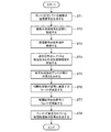
- FIG. 3 is a flowchart showing the processing contents of the sensor device according to Embodiment 1 of the present invention.
- components mounted on a general wireless device such as an amplifier, a frequency converter, a filter, an analog / digital converter, and a digital / analog converter are omitted. In reality, these components are provided.
- Information indicating the arrangement of the transmission antennas 2-1 to 2-3 and the reception antenna elements 3-1 to 3-N is stored in advance in the transmission / reception antenna information holding unit 7.
- the description will be made.
- the distance between the transmission antenna 2-1 and the transmission antenna 2-2 is dTX1
- the distance between the transmission antenna 2-2 and the transmission antenna 2-3 is dTX2 .
- the distance between the receiving antenna elements 3-1 receive antenna elements 3-2 d RX1
- distance between the receiving antenna elements 3-2 receive antenna elements 3-3 is assumed to be d RX2.
- the distance between the receiving antenna element 3- (N ⁇ 1) and the receiving antenna element 3-N is d RX (N ⁇ 1) .
- Transmission signal generation processing units 1-1 to 1-3 of the transmission signal generation unit 1 generate transmission signals (1) to (3) that are orthogonal to each other, and transmit the transmission signals (1) to (3). It outputs to the antenna part 2 (step ST1 of FIG. 3).
- the generation method of the transmission signals (1) to (3) that are orthogonal to each other is not particularly limited.
- the transmission signal generation processing units 1-1 to 1-3 may convert the same transmission signal into a Barker code, an M sequence, By modulating with a plurality of orthogonal code sequences such as a cold sequence, transmission signals (1) to (3) orthogonal to each other can be generated. Thereby, three transmission signals (1) to (3) orthogonal to each other are radiated into the space from the transmission antennas 2-1 to 2-3 of the transmission antenna unit 2 (step ST2).
- Equation (1) the difference in the path from the transmitting antennas 2-1 to 2-3 to the observation target is expressed by the following equation (1).
- ⁇ is the angle of the observation target with respect to the boresight direction of the array antenna when the transmission antennas 2-1 to 2-3 are considered as one array antenna.
- ⁇ is the wavelength of the transmission signals (1) to (3).
- the receiving antenna elements 3-1 to 3-N of the array antenna 3 receive the transmitted signals (1) to (3) that have been radiated from the transmitting antennas 2-1 to 2-3 and then reflected back to the observation target. A reflected wave is received (step ST3).
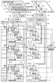
- the difference in path from the observation target to the receiving antenna elements 3-1 to 3-N is expressed by the following equation (2).
- ⁇ is the angle of the observation target with respect to the boresight direction of the array antenna 3.
- the replica generation unit 4 When the transmission signal generation processing units 1-1 to 1-3 generate the transmission signals (1) to (3), the replica generation unit 4 generates replicas of the transmission signals (1) to (3) and transmits the transmission signals. Replicas of the signals (1) to (3) are output to the correlation processing units 5-1 to 5-N.
- the cross-correlation calculating unit 5-1-1 receives the reflected waves of the transmission signals (1) to (3) that have been reflected back to the observation target by the receiving antenna element 3-1, and is generated by the replica generating unit 4. By performing cross-correlation processing between the replica of the transmitted signal (1) and the received signal of the receiving antenna element 3-1, the same waveform as that of the transmitted signal (1) is received from the received signals of the receiving antenna element 3-1.
- the signal correlated with the transmission signal (1) is extracted, and the signal is output to the weight application unit 9-1-1 as a signal after cross-correlation processing (step ST4).
- the replica of the transmission signal (1) is a signal sequence having a predetermined length
- the cross-correlation process between the replica of the transmission signal (1) and the reception signal is, for example, the replica of the transmission signal (1) By multiplying the reception signal, it can be realized by using a matched filter or the like that correlates the replica of the transmission signal (1) and the reception signal.
- the cross-correlation calculating unit 5-1-2 performs a cross-correlation process between the replica of the transmission signal (2) generated by the replica generation unit 4 and the reception signal of the reception antenna element 3-1, so that the reception antenna element A signal having the same waveform as the transmission signal (2) is extracted from the reception signal 3-1 and the signal is output to the weight application unit 9-1-2 as a signal after cross-correlation processing (step ST4).
- the cross-correlation calculating unit 5-1-3 performs a cross-correlation process between the replica of the transmission signal (3) generated by the replica generation unit 4 and the reception signal of the reception antenna element 3-1, so that the reception antenna element A signal having the same waveform as the transmission signal (3) is extracted from the reception signal 3-1 and the signal is output to the weight application unit 9-1-3 as a signal after cross-correlation processing (step ST4).
- the cross-correlation calculating units 5-2-1 to 5-2-3 of the correlation processing unit 5-2 are the same as the cross-correlation calculating units 5-1-1 to 5-1-1 of the correlation processing unit 5-1.
- Cross-correlation processing is performed, and signals after cross-correlation processing are output to weight application units 9-2-1 to 9-2-3 (step ST4).
- the cross-correlation calculators 5-2-1 to 5-2-3 perform the cross-correlation process on the reception signal of the reception antenna element 3-2, so that the cross-correlation calculators 5-1-1 to 5-1-2. It is different from 1-3.
- the cross-correlation calculation units 5-N-1 to 5-N-3 of the correlation processing unit 5-N are the same as the cross-correlation calculation units 5-1-1 to 5-1-1 of the correlation processing unit 5-1.
- Cross-correlation processing is performed, and the signals after cross-correlation processing are output to weight application units 9-N-1 to 9-N-3 (step ST4).
- the cross-correlation calculators 5-N-1 to 5-N-3 perform the cross-correlation process on the reception signal of the reception antenna element 3-N, and thus the cross-correlation calculators 5-1-1 to 5-N-5. It is different from 1-3.
- the antenna openings of the receiving antenna elements 3-1 to 3-N are virtually expanded.
- the length of the antenna aperture after the cross-correlation processing by the correlation processing units 5-1 to 5-N is based on the reception antenna element 3-1, as is clear from the above equations (3) to (5).
- the following equation (6) is obtained.
- Antenna aperture length after cross-correlation processing That is, the length of the antenna aperture after the cross-correlation processing is determined by the distance (d TX1 + d TX2 ) between the transmission antenna 2-1 and the transmission antenna 2-3, the reception antenna element 3-1 and the reception antenna element 3-N. (D RX1 + d RX2 +... + D RX (N ⁇ 1) ).
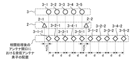
- FIG. 4 is an explanatory diagram showing the arrangement of the transmitting antenna and the receiving antenna element and the antenna aperture after the cross-correlation processing.
- FIG. 4 shows a case where two transmission antennas 2-1 and 2-2 and five reception antenna elements 3-1 to 3-5 are mounted for the sake of simplicity.
- the distance between the transmission antenna 2-1 and the reception antenna element 3-1 is d / 2
- the distance between the transmission antenna 2-2 and the reception antenna element 3-5 is d / 2.
- 3-1-1 to 3-5-1 are based on correlation processing between the replica of the transmission signal (1) radiated from the transmission antenna 2-1 and the reception signal of the reception antenna elements 3-1 to 3-5. This is an element arrangement of the receiving antenna elements 3-1 to 3-5. Further, 3-1-2 to 3-5-2 are used for correlation processing between the replica of the transmission signal (2) radiated from the transmission antenna 2-2 and the reception signals of the reception antenna elements 3-1 to 3-5. This is an element arrangement of the receiving antenna elements 3-1 to 3-5. Therefore, if the cross-correlation processing by the correlation processing units 5-1 to 5-5 is not performed, the aperture length of the array antenna 3 is 4d, but the cross-correlation processing by the correlation processing units 5-1 to 5-5 is not performed. By being implemented, the opening length of the array antenna 3 extends to 9d from the above equation (6).
- the weight determination unit 8 of the weighting unit 6 refers to information indicating the arrangement of the transmission antennas 2-1 to 2-3 and the reception antenna elements 3-1 to 3-N held in the transmission / reception antenna information holding unit 7. , The distance between the transmitting antenna 2-1 and the transmitting antenna 2-3 (d TX1 + d TX2 ) and the distance between the receiving antenna element 3-1 and the receiving antenna element 3-N (d RX1 + d RX2 +... + D RX (N-1) ) is specified, and the antenna aperture after the cross-correlation processing by the correlation processing units 5-1 to 5-N, that is, the reception antenna element 3- The lengths of the antenna openings 1 to 3-N are obtained (step ST5).
- the weight determination unit 8 obtains the length of the antenna aperture after the cross-correlation processing by the correlation processing units 5-1 to 5-N. However, the length of the antenna aperture after the cross-correlation processing is determined in advance. If it is specified and the length of the antenna opening is configured to be held in the transmission / reception antenna information holding unit 7, the weight determination unit 8 has the length of the antenna opening held in the transmission / reception antenna information holding unit 7. The length may be read out.
- the weight determining unit 8 obtains the length of the antenna opening of the receiving antenna elements 3-1 to 3-N, the amplitude distribution corresponding to the length of the antenna opening is held in the transmitting / receiving antenna information holding unit 7.
- a weight to be multiplied with the signal after cross-correlation processing output from N-3 is determined (step ST6).
- the weights are determined so as to match the antenna directivity pattern that is set, but when the antenna directivity pattern held in the transmission / reception antenna information holding unit 7 is related to the phase distribution, The weights are determined so that the phase distribution corresponding to the length of the antenna aperture matches the antenna directivity pattern held in the transmission / reception antenna information holding unit 7.
- the antenna directivity pattern held in the transmission / reception antenna information holding unit 7 relates to both the amplitude distribution and the phase distribution, the amplitude distribution and the phase distribution corresponding to the length of the antenna opening hold the transmission / reception antenna information.
- the weight is determined so as to match the antenna directivity pattern held in the unit 7.
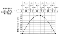
- FIG. 5 is an explanatory view showing the amplitude distribution of weights when an arbitrary function applied to the antenna aperture after cross-correlation processing is a cosine distribution.
- FIG. 5 shows a case where two transmitting antennas 2-1 and 2-2 and five receiving antenna elements 3-1 to 3-5 are arranged as shown in FIG. Cosine distribution with respect to virtual element arrangements 3-1-1 to 3-5-1 and 3-1-21 to 3-5-2 of receiving antenna elements 3-1 to 3-5 at the processed antenna aperture Has been applied.
- FIG. 5 shows a case where two transmitting antennas 2-1 and 2-2 and five receiving antenna elements 3-1 to 3-5 are arranged as shown in FIG. Cosine distribution with respect to virtual element arrangements 3-1-1 to 3-5-1 and 3-1-21 to 3-5-2 of receiving antenna elements 3-1 to 3-5 at the processed antenna aperture Has been applied.
- FIG. 5 shows a case where two transmitting antennas 2-1 and 2-2 and five receiving antenna elements 3-1 to 3-5 are arranged as shown in FIG. Cosine distribution with respect to virtual element arrangements 3-1-1 to 3-5-1 and 3-1-21 to 3-5-2 of receiving antenna elements 3-1 to 3-5 at the processed antenna aperture Has been applied.
- FIG. 5 shows a case where two transmitting antennas
- the weights of the virtual element arrangements 3-1-1 and 3-5-2 of the receiving antenna elements 3-1 to 3-5 at the antenna aperture after the cross-correlation processing are about 0.0
- the weight of the arrangement 3-2-1, 3-4-2 is about 0.34
- the weight of the element arrangement 3-3-1, 3-3-2 is about 0.64
- the element arrangement 3-4-1, 3 The weight of -2-2 is determined to be about 0.87
- the weight of the element arrangements 3-5-1 and 3-1-2 is determined to be about 0.98.
- this weight is only an example.
- the weight application units 9-1-1 to 9-1-3, 9-2-1 to 9-2-3, ..., 9-N-1 to 9-N-3 of the weighting unit 6 determine the weights.
- the unit 8 determines a weight
- the weights are converted into cross-correlation calculating units 5-1-1 to 5-1-3, 5-2-1 to 5-2-3,..., 5-N-1 to 5
- the signal after cross-correlation processing output from ⁇ N ⁇ 3 is multiplied, and the signal after cross-correlation processing multiplied by the weight is output to the signal synthesis unit 10 (step ST7).
- the weight determination unit 8 sets the amplitude a w, since the weights are represented by a complex signal a w e j ⁇ w phase phi w is determined, in each of the weight application unit, the multiplication of a r e j ⁇ r ⁇ a w e j ⁇ w performed.
- the signal synthesis unit 10 includes weight application units 9-1-1 to 9-1-3, 9-2-1 to 9-2-3, ..., 9-N-1 to 9-N-3.
- the signal after the correlation processing is multiplied by the weight
- the signal after the cross-correlation processing multiplied by the weight is combined and the combined signal is output (step ST8).
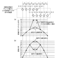
- FIG. 6 is an explanatory diagram showing an example of a directivity pattern obtained by the sensor device according to Embodiment 1 of the present invention.
- FIG. 6 shows a case where the number of transmission antennas is 2, the number of reception antenna elements is 10, the interval between the reception antenna elements is a half wavelength, and the interval between the transmission antennas is 5 wavelengths.
- the transmitting antenna and the receiving antenna element are arranged in a straight line, the interval between the transmitting antenna and the receiving antenna element closest to the transmitting antenna is wavelength / 4, and an arbitrary function that gives amplitude characteristics is a cosine distribution. Is shown.
- replicas of a plurality of transmission signals (1) to (3) orthogonal to each other and the receiving antenna elements 3-1 (3-2,... 3-N) a correlation processing unit 5-1 (5-2,..., 5-N) that performs cross-correlation processing with the received signal and outputs a plurality of signals after cross-correlation processing;
- the aperture length of the 3-N array antenna 3 is virtually expanded. An effect that can bet. Thereby, the directivity of the antenna can be increased and a desired directivity pattern can be obtained.
- the transmission antennas 2-1 to 2-3 and the reception antenna elements 3-1 to 3-N are one-dimensionally arranged.
- a plurality of transmission antennas and a plurality of reception antenna elements are shown. May be arranged two-dimensionally.
- an example of obtaining one directivity pattern is shown, but a plurality of different directivity patterns may be obtained.
- the weight application units 9-1-1 to 9-1-3, 9-2-1 to 9-2-3, 9-N-1 to 9-N-3 and the signal synthesis unit 10 are directed to the respective directions. It may be implemented for each sex pattern.
- FIG. 1 an example in which two transmitting antennas 2-1 and 2-2 and five receiving antenna elements 3-1 to 3-5 are mounted is shown in FIG. .
- the receiving antenna elements 3-1 to 3-5 do not have the receiving antenna elements arranged at the positions overlapping with the transmitting antennas 2-1 and 2-2.
- the antenna elements 3-1 to 3-5 there may be a receiving antenna element arranged at a position overlapping the positions of the transmission antennas 2-1 and 2-2.
- the configuration of the sensor device is the same as the configuration of FIG. 1 in the first embodiment.
- FIG. 7 is an explanatory diagram showing the arrangement of the transmitting antenna and the receiving antenna element and the antenna aperture after the cross-correlation processing.
- FIG. 7 shows a case where two transmission antennas 2-1 and 2-2 and five reception antenna elements 3-1 to 3-5 are mounted for the sake of simplicity.
- the position of the transmitting antenna 2-1 and the receiving antenna element 3-1 in the alignment direction is the same, and the position of the transmitting antenna 2-2 and the receiving antenna element 3-3 in the alignment direction are the same.
- 3-1-1 to 3-5-1 are based on correlation processing between the replica of the transmission signal (1) radiated from the transmission antenna 2-1 and the reception signal of the reception antenna elements 3-1 to 3-5. This is an element arrangement of the receiving antenna elements 3-1 to 3-5. Further, 3-1-2 to 3-5-2 are used for correlation processing between the replica of the transmission signal (2) radiated from the transmission antenna 2-2 and the reception signals of the reception antenna elements 3-1 to 3-5. This is an element arrangement of the receiving antenna elements 3-1 to 3-5. Therefore, if the cross-correlation processing by the correlation processing units 5-1 to 5-N is not performed, the aperture length of the array antenna 3 is 4d, but the cross-correlation processing by the correlation processing units 5-1 to 5-N is not performed.
- the opening length of the array antenna 3 is expanded to 7d from the above equation (6).
- the positions of the transmitting antenna 2-1 and the receiving antenna element 3-1 in the alignment direction are the same, and the positions of the transmitting antenna 2-2 and the receiving antenna element 3-3 in the alignment direction are the same. Are the same. Therefore, the element arrangement 3-4-1 and the element arrangement 3-1-2 overlap, and the element arrangement 3-5-1 and the element arrangement 3-2-2 overlap.
- FIG. 8 is an explanatory diagram showing the amplitude distribution of weights when an arbitrary function applied to the antenna aperture after cross-correlation processing is a cosine distribution.
- the weight determination unit 8 of the weighting unit 6 obtains the length of the antenna opening after the cross-correlation processing, as in the first embodiment, and the amplitude distribution corresponding to the length of the antenna opening is the transmission / reception antenna information holding unit. 7 is determined so as to match the antenna directivity pattern held in FIG. However, as shown in FIG. 7, when the element arrangements 3-4-1, 3-5-1 and the element arrangements 3-1-2, 3-2-2 overlap, the weights are the same as in the first embodiment. 8A, since the signals after the two cross-correlation processes overlap in the overlapping element arrangement as shown in FIG. 8A, the input signal at the overlapped position to the signal synthesizer 10 has a desired amplitude. It will double.
- the weight determining unit 8 of the weighting unit 6 is configured so that the element arrangement 3-4-1, 3-5-1 and the element arrangement 3-1-2, 3-2-2 overlap.
- the cross-correlation calculation unit and the weight application unit corresponding to the element arrangement 3-4-1, 3-5-1, 3-1-2, 3-2-2 are respectively cross-correlation calculation units 5-4-1, 5 -5-1, 5-1-2, 5-2-2, and weight application units 9-4-1, 9-5-1, 9-1-2, 9-2-2.
- Weights to be multiplied with signals output from the arithmetic units 5-1-1 to 5-3-1 and 5-3-2 to 5-5-2 are determined in the same manner as in the first embodiment.
- the weights to be multiplied with the signals output from the cross-correlation computing units 5-4-1, 5-5-1, 5-1-2, and 5-2-2 are determined in the same manner as in the first embodiment. Is determined to be half of the weight.
- the weight applying units 9-1-1 to 9-5-1 and 9-1-2 to 9-5-2 of the weighting unit 6 convert the weights into the cross-correlation calculating unit 5 -1-1 to 5-5-1 and 5-1-2 to 5-5-2, the signal after cross-correlation processing is multiplied and the signal after cross-correlation processing multiplied by the weight is signal synthesizer 10 is output.
- the weight applying units 9-1-1 to 9-5-1 and 9-1-2 to 9-5-2 multiply the signals after cross-correlation processing by the weights
- the signal combining unit 10 multiplies the weights.
- the signals after cross-correlation processing are combined and the combined signal is output.
- the weight for multiplying the signal output from the cross-correlation computing units 5-4-1, 5-5-1, 5-1-2, and 5-2-2 is determined to be a half.
- the cross-correlations output from the weight application units 9-4-1 and 9-1-2 are compared with those in the first embodiment.
- the processed signal is halved.
- the overlapping element arrangement 3-5-1 and element arrangement 3-2-2 as compared with the first embodiment, the mutual outputs output from the weight application units 9-5-1 and 9-2-2.
- the signal after the correlation processing is halved.
- the desired antenna directivity pattern held in the transmission / reception antenna information holding unit 7 matches the amplitude distribution.
- the weight at the position where the element arrangements overlap is determined to be half of the weight determined in the same manner as in the first embodiment.
- the element arrangements overlap.
- the weight at a certain position is determined in the same manner as in the first embodiment, and the weight at a position where the element arrangement is not overlapped is determined to be twice the weight determined in the same manner as in the first embodiment. You may make it adjust the amplitude of each element arrangement
- the number of positions where the element arrangements overlap is two, the number of positions where the element arrangements overlap is determined to be one half of the weight. If so, it may be determined to be 1 / M of the weight.
- the reception antenna elements 3-1 to 3-5 that are disposed at positions overlapping the positions of the transmission antennas 2-1 and 2-2 are arranged. Even when there is an antenna element, the aperture length of the array antenna 3 composed of the receiving antenna elements 3-1 to 3-5 can be virtually widened as in the first embodiment. Thereby, the directivity of the antenna can be increased and a desired directivity pattern can be obtained.
- FIG. 9 is a block diagram showing a sensor device according to Embodiment 3 of the present invention.
- the directivity switching unit 31 is a device that switches the directivities of the transmission antennas 2-1 to 2-3 under the control of the timing control unit 32.
- the directivity switching unit 31 may be configured by a driving device such as a motor that physically switches the direction of the transmission antennas 2-1 to 2-3, or the radiation from the transmission antennas 2-1 to 2-3.
- the transmission signals (1) to (3) may be configured to be optically switched, and the transmission antennas 2-1 to 2-3 are composed of a plurality of elements, and the transmission antenna unit 2 When the transmitting antennas 2-1 to 2-3 are subarrays, they may be switched electrically.
- the timing control unit 32 is a control circuit that controls the directivity switching timing by the directivity switching unit 31.
- the transmission antennas 2-1 to 2-3 radiate transmission signals (1) to (3) that are orthogonal to each other.
- FIG. When a satellite equipped with a sensor device is moving, or when the observation target is moving, Doppler shift occurs due to the movement, so the transmission antennas 2-1 to 2-3 change the observation target.
- the orthogonality of the received signals of the receiving antenna elements 3-1 to 3-N may be slightly disrupted due to the influence of the path difference to reach.
- the directivity switching unit 31 and the timing control unit 32 are mounted in order to maintain the orthogonality of the received signals of the receiving antenna elements 3-1 to 3-N.
- the timing control unit 32 controls the directivity switching timing by the directivity switching unit 31. That is, the timing control unit 32 sends a directivity switching command to the directivity switching unit 31 and the transmission signal generation processing units 1-1 to 1-3 at the timing for switching the directivities of the transmission antennas 2-1 to 2-3. Output to.
- the directivity switching unit 31 receives a directivity switching command from the timing control unit 32, the directivity switching unit 31 performs an operation of switching the directivities of the transmission antennas 2-1 to 2-3.
- the transmission signal generation processing units 1-1 to 1-3 generate transmission signals (1) to (3) that are orthogonal to each other, and transmit the transmission signal (1).
- To (3) are output to the transmission antennas 2-1 to 2-3, but at the timing when the directivity of the transmission antennas 2-1 to 2-3 is switched by the directivity switching unit 31, the transmission signal (1)
- the transmission antennas 2-1 to 2-3 are transmitted for a predetermined time. Stops outputting the transmission signals (1) to (3).
- FIG. 10 is an explanatory diagram showing an example of the directivity pattern of the transmission antennas 2-1 to 2-3.
- three directivity patterns (1) to (3) are prepared, and the directivity patterns (1) to (3) for the transmission antennas 2-1 to 2-3 are prepared.
- An example will be described in which the assignments are switched in order.
- the directivity patterns (1) to (3) are directivity patterns in which main lobes having the highest gain do not overlap each other.
- a switching example of the directivity patterns (1) to (3) by the directivity switching unit 31 will be specifically described.
- the third embodiment is applied when the observation target exists only in any one of the directions indicated by the directivity patterns (1) to (3).
- the directivity patterns (1) to (3) are transmitted to the transmitting antennas 2-1 to 2-3 as follows. Assign to. Directivity pattern (1) ⁇ Transmitting antenna 2-1 Directivity pattern (2) ⁇ Transmitting antenna 2-2 Directivity pattern (3) ⁇ Transmitting antenna 2-3
- the directivity patterns (1) to (3) are transmitted to the transmitting antennas 2-1 to 2-3 as follows. Assign to. Directivity pattern (2) ⁇ Transmitting antenna 2-1 Directivity pattern (3) ⁇ Transmitting antenna 2-2 Directivity pattern (1) ⁇ Transmitting antenna 2-3
- the directivity patterns (1) to (3) are transmitted to the transmitting antennas 2-1 to 2-3 as follows. Assign to. Directivity pattern (3) ⁇ Transmitting antenna 2-1 Directivity pattern (1)-> transmit antenna 2-2 Directivity pattern (2) ⁇ Transmitting antenna 2-3
- the observation target exists only in the direction indicated by the directivity pattern (1).
- the reflected wave of the transmission signal radiated in the direction indicated by the directivity patterns (2) and (3) is not received by the receiving antenna elements 3-1 to 3-N. Therefore, the orthogonality of the received signals of the receiving antenna elements 3-1 to 3-N is maintained even if a Doppler shift occurs due to the movement of the satellite or the like carrying the sensor device of FIG. be able to.
- the directivity switching unit 31 is configured to switch the directivities of the transmission antennas 2-1 to 2-3 under the control of the timing control unit 32.
- the orthogonality of the received signals of the receiving antenna elements 3-1 to 3-N can be maintained even when a satellite or the like on which the sensor device is mounted is moving or the observation target is moving. . For this reason, a desired directivity pattern can be obtained with high accuracy.
- the sensor device according to the present invention is suitable for a device that needs to increase the antenna directivity by virtually expanding the aperture length of an array antenna composed of a plurality of receiving antenna elements.
- Transmission signal generation unit 1-1 to 1-3 Transmission signal generation processing unit, 2 Transmission antenna unit, 2-1 to 2-3 transmission antenna, 3 array antenna, 3-1 to 3-N reception antenna element, 3 -1-1 to 3-5-1, 3-1-2 to 3-5-2: Element arrangement of receiving antenna elements based on correlation processing, 4 replica generation unit, 5-1 to 5-N correlation processing unit, 5 -1-1 to 5-1-3, 5-2-1 to 5-2-3, 5-N-1 to 5-N-3, cross-correlation calculation unit, 6 weighting unit, 7 transmitting / receiving antenna information holding unit, 8 Weight determination unit, 9-1-1 to 9-1-3, 9-2-1 to 9-2-3, 9-N-1 to 9-N-3 Weight application unit, 10 signal synthesis unit, 21 Memory, 22 processor, 31 directivity switching unit, 32 timing control unit.
Abstract
This sensor apparatus is provided with: correlation processing units 5-1 (5-2,..., 5-N) that perform cross-correlation processing on replicas of a plurality of transmission signals orthogonal to each other and reception signals of reception antenna elements 3-1 (3-2,..., 3-N), and output a plurality of post-cross-correlation-processing signals; and a weighting unit 6 that, in accordance with the arrangement of transmission antennas 2-1 to 2-3 and the reception antenna elements 3-1 to 3-N and an antenna directional pattern, weights the plurality of post-cross-correlation-processing signals output from the correlation processing units 5-1 to 5-N, and a signal combining unit 10 combines the plurality of post-cross-correlation-processing signals that have been weighted by the weighting unit 6.
Description
この発明は、例えば、移動体や静止物体などの観測対象の位置や速度などを観測するレーダ装置が、レーダ信号を送受信する際に用いるセンサ装置に関するものである。
The present invention relates to a sensor device used when a radar device that observes the position and speed of an observation target such as a moving object or a stationary object transmits and receives a radar signal.
センサ装置におけるアンテナの指向性パターンが、所望の指向性パターンとなるようにするために、従来より、アレイアンテナを構成している複数のアンテナ素子の受信信号に対する重み付けの方法や、複数のアンテナ素子を配置する方法などが広く検討されている。
例えば、以下の特許文献1には、アレイアンテナをサブアレイに分割し、サブアレイ単位で重み付けを行うことで、サイドローブを低減する方法が開示されている。
また、以下の特許文献2には、アレイアンテナを構成している複数のアンテナ素子の間隔をフィボナッチ数列にしたがって決定することで、サイドローブを低減する方法が開示されている。 Conventionally, a method for weighting received signals of a plurality of antenna elements constituting an array antenna, and a plurality of antenna elements so that the antenna directivity pattern in the sensor device becomes a desired directivity pattern. The method of arranging the device has been widely studied.
For example,Patent Document 1 below discloses a method of reducing side lobes by dividing an array antenna into subarrays and performing weighting in units of subarrays.
Patent Document 2 below discloses a method for reducing side lobes by determining intervals between a plurality of antenna elements constituting an array antenna according to a Fibonacci sequence.
例えば、以下の特許文献1には、アレイアンテナをサブアレイに分割し、サブアレイ単位で重み付けを行うことで、サイドローブを低減する方法が開示されている。
また、以下の特許文献2には、アレイアンテナを構成している複数のアンテナ素子の間隔をフィボナッチ数列にしたがって決定することで、サイドローブを低減する方法が開示されている。 Conventionally, a method for weighting received signals of a plurality of antenna elements constituting an array antenna, and a plurality of antenna elements so that the antenna directivity pattern in the sensor device becomes a desired directivity pattern. The method of arranging the device has been widely studied.
For example,
従来のセンサ装置は以上のように構成されているので、サイドローブを低減することが可能であるが、アンテナの指向性を高めるために、1つ以上の受信アンテナ素子からなるアレイアンテナの開口長を仮想的に広げることができないという課題があった。
Since the conventional sensor device is configured as described above, the side lobe can be reduced. However, in order to increase the directivity of the antenna, the aperture length of the array antenna including one or more receiving antenna elements is used. There was a problem that it was not possible to virtually expand.
この発明は上記のような課題を解決するためになされたもので、複数の受信アンテナ素子からなるアレイアンテナの開口長を仮想的に広げることができるセンサ装置を得ることを目的とする。
The present invention has been made to solve the above-described problems, and an object of the present invention is to obtain a sensor device that can virtually widen the aperture length of an array antenna composed of a plurality of receiving antenna elements.
この発明に係るセンサ装置は、互いに直交している複数の送信信号を生成する送信信号生成部と、複数の送信アンテナから送信信号生成部により生成された送信信号を空間に放射する送信アンテナ部と、複数の送信アンテナから放射された後、観測対象に反射された送信信号の反射波を受信する1つ以上の受信アンテナ素子からなるアレイアンテナと、複数の送信信号と受信アンテナ素子の受信信号との相互相関処理を実施して、複数の相互相関処理後の信号を出力する複数の相関処理部と、送信アンテナ及び受信アンテナ素子の配置とアンテナ指向性パターンにしたがって複数の相関処理部から出力された複数の相互相関処理後の信号に重み付けを行う重み付け部とを設け、信号合成部が、重み付け部により重み付けが行われた複数の相互相関処理後の信号を合成するようにしたものである。
A sensor device according to the present invention includes: a transmission signal generation unit that generates a plurality of transmission signals that are orthogonal to each other; and a transmission antenna unit that radiates transmission signals generated by the transmission signal generation unit from a plurality of transmission antennas into space. An array antenna composed of one or more receiving antenna elements that receive a reflected wave of a transmission signal that is radiated from a plurality of transmitting antennas and then reflected by an observation target; and a plurality of transmission signals and reception signals of the receiving antenna elements Are output from a plurality of correlation processing units according to the arrangement and antenna directivity pattern of transmission antennas and reception antenna elements, and a plurality of correlation processing units that output a plurality of signals after cross-correlation processing. A weighting unit for weighting a plurality of signals after cross-correlation processing, and the signal synthesis unit includes a plurality of phases weighted by the weighting unit. It is obtained so as to synthesize the signal after correlation processing.
この発明によれば、互いに直交している複数の送信信号と受信アンテナ素子の受信信号との相互相関処理を実施して、複数の相互相関処理後の信号を出力する複数の相関処理部と、送信アンテナ及び受信アンテナ素子の配置とアンテナ指向性パターンにしたがって複数の相関処理部から出力された複数の相互相関処理後の信号に重み付けを行う重み付け部とを設け、信号合成部が、重み付け部により重み付けが行われた複数の相互相関処理後の信号を合成するように構成したので、1つ以上の受信アンテナ素子からなるアレイアンテナの開口長を仮想的に広げることができる効果がある。
According to the present invention, a plurality of correlation processing units that perform a cross-correlation process between a plurality of transmission signals orthogonal to each other and a reception signal of a reception antenna element, and output a plurality of signals after cross-correlation processing; A weighting unit for weighting a plurality of signals after cross-correlation processing output from the plurality of correlation processing units according to the arrangement of the transmitting antenna and the receiving antenna element and the antenna directivity pattern; Since the configuration is such that a plurality of weighted signals after cross-correlation processing are combined, there is an effect that the aperture length of the array antenna composed of one or more receiving antenna elements can be virtually expanded.
以下、この発明をより詳細に説明するために、この発明を実施するための形態について、添付の図面にしたがって説明する。
Hereinafter, in order to explain the present invention in more detail, modes for carrying out the present invention will be described with reference to the accompanying drawings.
実施の形態1.
図1はこの発明の実施の形態1によるセンサ装置を示す構成図である。
図1において、送信信号生成部1は互いに直交している複数の送信信号を生成し、複数の送信信号を送信アンテナ部2に出力する。
図1の例では、送信信号生成部1が3つの送信信号生成処理部1-1~1-3を備え、互いに直交している3つの送信信号を生成しているが、これは一例に過ぎず、互いに直交している2つ以上の送信信号を生成するものであればよい。Embodiment 1 FIG.
1 is a block diagram showing a sensor device according toEmbodiment 1 of the present invention.
In FIG. 1, a transmissionsignal generation unit 1 generates a plurality of transmission signals orthogonal to each other and outputs the plurality of transmission signals to the transmission antenna unit 2.
In the example of FIG. 1, the transmissionsignal generation unit 1 includes three transmission signal generation processing units 1-1 to 1-3 and generates three transmission signals that are orthogonal to each other, but this is only an example. Instead, any device that generates two or more transmission signals orthogonal to each other may be used.
図1はこの発明の実施の形態1によるセンサ装置を示す構成図である。
図1において、送信信号生成部1は互いに直交している複数の送信信号を生成し、複数の送信信号を送信アンテナ部2に出力する。
図1の例では、送信信号生成部1が3つの送信信号生成処理部1-1~1-3を備え、互いに直交している3つの送信信号を生成しているが、これは一例に過ぎず、互いに直交している2つ以上の送信信号を生成するものであればよい。
1 is a block diagram showing a sensor device according to
In FIG. 1, a transmission
In the example of FIG. 1, the transmission
送信信号生成処理部1-1~1-3は、互いに異なる時間、互いに異なる周波数及び互いに異なる符号のうち、いずれか1つ又は複数を用いて、互いに直交している送信信号(1)~(3)を生成する。
例えば、互いに異なる符号を用いて、互いに直交している送信信号(1)~(3)を生成する方法として、バーカーコード、M系列、コールド系列などの直交している複数の符号系列によって送信信号を変調することで、互いに直交している送信信号(1)~(3)を生成するものが考えられる。
また、互いに異なる周波数を用いて、互いに直交している送信信号(1)~(3)を生成する方法として、互い直交している搬送波であるサブキャリアで送信信号を変調することで、互いに直交している送信信号(1)~(3)を生成するものが考えられる。
また、互いに異なる時間を用いて、互いに直交している送信信号(1)~(3)を生成する方法として、送信信号(1)~(3)の生成時刻を変えることで、送信信号(1)~(3)の送信時刻を変えるものが考えられる。 The transmission signal generation processing units 1-1 to 1-3 use transmission signals (1) to (1) that are orthogonal to each other using one or more of different times, different frequencies, and different codes. 3) is generated.
For example, as a method for generating transmission signals (1) to (3) that are orthogonal to each other using different codes, the transmission signals are transmitted by a plurality of orthogonal code sequences such as a Barker code, an M sequence, and a cold sequence. Can be considered to generate transmission signals (1) to (3) that are orthogonal to each other.
Further, as a method of generating transmission signals (1) to (3) that are orthogonal to each other using different frequencies, the transmission signals are orthogonalized by modulating the transmission signals with subcarriers that are orthogonal to each other. It is conceivable that the transmission signals (1) to (3) are generated.
Further, as a method of generating transmission signals (1) to (3) that are orthogonal to each other using different times, transmission signals (1) to (3) are generated by changing the generation times of transmission signals (1) to (3). ) To (3) that change the transmission time can be considered.
送信アンテナ部2は送信アンテナ2-1~2-3から構成されており、送信信号生成部1から出力された3つの送信信号(1)~(3)を空間に放射する。
即ち、送信アンテナ2-1は送信信号生成処理部1-1により生成された送信信号(1)を空間に放射する。
送信アンテナ2-2は送信信号生成処理部1-2により生成された送信信号(2)を空間に放射する。
送信アンテナ2-3は送信信号生成処理部1-3により生成された送信信号(3)を空間に放射する。 Thetransmission antenna unit 2 includes transmission antennas 2-1 to 2-3, and radiates three transmission signals (1) to (3) output from the transmission signal generation unit 1 to space.
That is, the transmission antenna 2-1 radiates the transmission signal (1) generated by the transmission signal generation processing unit 1-1 to the space.
The transmission antenna 2-2 radiates the transmission signal (2) generated by the transmission signal generation processing unit 1-2 into space.
The transmission antenna 2-3 radiates the transmission signal (3) generated by the transmission signal generation processing unit 1-3 to the space.
即ち、送信アンテナ2-1は送信信号生成処理部1-1により生成された送信信号(1)を空間に放射する。
送信アンテナ2-2は送信信号生成処理部1-2により生成された送信信号(2)を空間に放射する。
送信アンテナ2-3は送信信号生成処理部1-3により生成された送信信号(3)を空間に放射する。 The
That is, the transmission antenna 2-1 radiates the transmission signal (1) generated by the transmission signal generation processing unit 1-1 to the space.
The transmission antenna 2-2 radiates the transmission signal (2) generated by the transmission signal generation processing unit 1-2 into space.
The transmission antenna 2-3 radiates the transmission signal (3) generated by the transmission signal generation processing unit 1-3 to the space.
アレイアンテナ3は受信アンテナ素子3-1~3-Nから構成されている。
受信アンテナ素子3-1~3-Nは送信アンテナ2-1~2-3から放射された後、例えば、移動体や静止物体などの観測対象に反射されて戻ってきた送信信号(1)~(3)の反射波を受信する。
図1では、アレイアンテナ3が、N本の受信アンテナ素子3-1~3-Nから構成されている例を示しているが、アレイアンテナ3は、1本以上の受信アンテナ素子を備えていればよい。 Thearray antenna 3 includes receiving antenna elements 3-1 to 3-N.
After the receiving antenna elements 3-1 to 3-N are radiated from the transmitting antennas 2-1 to 2-3, for example, the transmission signals (1) to (1) to return after being reflected by an observation target such as a moving object or a stationary object. The reflected wave of (3) is received.
FIG. 1 shows an example in which thearray antenna 3 is composed of N reception antenna elements 3-1 to 3-N. However, the array antenna 3 may include one or more reception antenna elements. That's fine.
受信アンテナ素子3-1~3-Nは送信アンテナ2-1~2-3から放射された後、例えば、移動体や静止物体などの観測対象に反射されて戻ってきた送信信号(1)~(3)の反射波を受信する。
図1では、アレイアンテナ3が、N本の受信アンテナ素子3-1~3-Nから構成されている例を示しているが、アレイアンテナ3は、1本以上の受信アンテナ素子を備えていればよい。 The
After the receiving antenna elements 3-1 to 3-N are radiated from the transmitting antennas 2-1 to 2-3, for example, the transmission signals (1) to (1) to return after being reflected by an observation target such as a moving object or a stationary object. The reflected wave of (3) is received.
FIG. 1 shows an example in which the
レプリカ生成部4は送信信号生成処理部1-1~1-3により生成された送信信号(1)~(3)のレプリカを生成し、その送信信号(1)~(3)のレプリカを相関処理部5-1~5-Nに出力する。
図1では、レプリカ生成部4が送信信号(1)~(3)のレプリカを相関処理部5-1~5-Nに出力する例を示しているが、送信信号生成処理部1-1~1-3が送信信号(1)~(3)を相関処理部5-1~5-Nに出力するようにしてもよい。この場合、レプリカ生成部4を省略することができる。ただし、レプリカ生成部4を実装することで、送信信号生成部1と相関処理部5-1~5-Nの設置位置が遠く離れている場合でも、送信アンテナ2-1~2-3から放射される送信信号(1)~(3)と同じ信号を相関処理部5-1~5-Nに与えることができる。 The replica generation unit 4 generates replicas of the transmission signals (1) to (3) generated by the transmission signal generation processing units 1-1 to 1-3, and correlates the replicas of the transmission signals (1) to (3). Output to the processing units 5-1 to 5-N.
FIG. 1 shows an example in which the replica generation unit 4 outputs replicas of the transmission signals (1) to (3) to the correlation processing units 5-1 to 5-N, but the transmission signal generation processing units 1-1 to 1-3 may output the transmission signals (1) to (3) to the correlation processing units 5-1 to 5-N. In this case, the replica generation unit 4 can be omitted. However, by mounting the replica generation unit 4, even when the installation positions of the transmissionsignal generation unit 1 and the correlation processing units 5-1 to 5-N are far apart, the radiation is transmitted from the transmission antennas 2-1 to 2-3. The same signals as the transmitted signals (1) to (3) can be given to the correlation processors 5-1 to 5-N.
図1では、レプリカ生成部4が送信信号(1)~(3)のレプリカを相関処理部5-1~5-Nに出力する例を示しているが、送信信号生成処理部1-1~1-3が送信信号(1)~(3)を相関処理部5-1~5-Nに出力するようにしてもよい。この場合、レプリカ生成部4を省略することができる。ただし、レプリカ生成部4を実装することで、送信信号生成部1と相関処理部5-1~5-Nの設置位置が遠く離れている場合でも、送信アンテナ2-1~2-3から放射される送信信号(1)~(3)と同じ信号を相関処理部5-1~5-Nに与えることができる。 The replica generation unit 4 generates replicas of the transmission signals (1) to (3) generated by the transmission signal generation processing units 1-1 to 1-3, and correlates the replicas of the transmission signals (1) to (3). Output to the processing units 5-1 to 5-N.
FIG. 1 shows an example in which the replica generation unit 4 outputs replicas of the transmission signals (1) to (3) to the correlation processing units 5-1 to 5-N, but the transmission signal generation processing units 1-1 to 1-3 may output the transmission signals (1) to (3) to the correlation processing units 5-1 to 5-N. In this case, the replica generation unit 4 can be omitted. However, by mounting the replica generation unit 4, even when the installation positions of the transmission
相関処理部5-1は相互相関演算部5-1-1~5-1-3から構成されている。
相互相関演算部5-1-1はレプリカ生成部4により生成された送信信号(1)のレプリカと受信アンテナ素子3-1の受信信号との相互相関処理を実施することで、受信アンテナ素子3-1の受信信号の中から、送信信号(1)と同一波形の信号(送信信号(1)と相関がとれている信号)を抽出し、その信号を相互相関処理後の信号として出力する。
相互相関演算部5-1-2はレプリカ生成部4により生成された送信信号(2)のレプリカと受信アンテナ素子3-1の受信信号との相互相関処理を実施することで、受信アンテナ素子3-1の受信信号の中から、送信信号(2)と同一波形の信号(送信信号(2)と相関がとれている信号)を抽出し、その信号を相互相関処理後の信号として出力する。
相互相関演算部5-1-3はレプリカ生成部4により生成された送信信号(3)のレプリカと受信アンテナ素子3-1の受信信号との相互相関処理を実施することで、受信アンテナ素子3-1の受信信号の中から、送信信号(3)と同一波形の信号(送信信号(3)と相関がとれている信号)を抽出し、その信号を相互相関処理後の信号として出力する。 The correlation processing unit 5-1 includes cross-correlation calculation units 5-1-1 to 5-1-3.
The cross-correlation calculating unit 5-1-1 performs the cross-correlation process between the replica of the transmission signal (1) generated by the replica generation unit 4 and the reception signal of the reception antenna element 3-1, so that the reception antenna element 3 A signal having the same waveform as that of the transmission signal (1) (a signal correlated with the transmission signal (1)) is extracted from the reception signal of −1, and the signal is output as a signal after cross-correlation processing.
The cross-correlation calculation unit 5-1-2 performs cross-correlation processing between the replica of the transmission signal (2) generated by the replica generation unit 4 and the reception signal of the reception antenna element 3-1, thereby receiving the reception antenna element 3 A signal having the same waveform as the transmission signal (2) (a signal correlated with the transmission signal (2)) is extracted from the received signal of −1, and the signal is output as a signal after cross-correlation processing.
The cross-correlation calculating unit 5-1-3 performs the cross-correlation process between the replica of the transmission signal (3) generated by the replica generation unit 4 and the reception signal of the reception antenna element 3-1, so that the reception antenna element 3 A signal having the same waveform as the transmission signal (3) (a signal correlated with the transmission signal (3)) is extracted from the received signal of −1, and the signal is output as a signal after cross-correlation processing.
相関処理部5-2は相互相関演算部5-2-1~5-2-3から構成されている。
相互相関演算部5-2-1はレプリカ生成部4により生成された送信信号(1)のレプリカと受信アンテナ素子3-2の受信信号との相互相関処理を実施することで、受信アンテナ素子3-2の受信信号の中から、送信信号(1)と同一波形の信号を抽出し、その信号を相互相関処理後の信号として出力する。
相互相関演算部5-2-2はレプリカ生成部4により生成された送信信号(2)のレプリカと受信アンテナ素子3-2の受信信号との相互相関処理を実施することで、受信アンテナ素子3-2の受信信号の中から、送信信号(2)と同一波形の信号を抽出し、その信号を相互相関処理後の信号として出力する。
相互相関演算部5-2-3はレプリカ生成部4により生成された送信信号(3)のレプリカと受信アンテナ素子3-2の受信信号との相互相関処理を実施することで、受信アンテナ素子3-2の受信信号の中から、送信信号(3)と同一波形の信号を抽出し、その信号を相互相関処理後の信号として出力する。 The correlation processing unit 5-2 includes cross-correlation calculation units 5-2-1 to 5-2-3.
The cross-correlation calculation unit 5-2-1 performs cross-correlation processing between the replica of the transmission signal (1) generated by the replica generation unit 4 and the reception signal of the reception antenna element 3-2, so that the reception antenna element 3 -2 extracts a signal having the same waveform as that of the transmission signal (1), and outputs the signal as a signal after cross-correlation processing.
The cross-correlation calculating unit 5-2-2 performs a cross-correlation process between the replica of the transmission signal (2) generated by the replica generation unit 4 and the reception signal of the reception antenna element 3-2, so that the reception antenna element 3 -2 extracts a signal having the same waveform as that of the transmission signal (2), and outputs the signal as a signal after cross-correlation processing.
The cross-correlation calculation unit 5-2-3 performs cross-correlation processing between the replica of the transmission signal (3) generated by the replica generation unit 4 and the reception signal of the reception antenna element 3-2, thereby receiving the reception antenna element 3 -2 extracts a signal having the same waveform as that of the transmission signal (3), and outputs the signal as a signal after cross-correlation processing.
相関処理部5-Nは相互相関演算部5-N-1~5-N-3から構成されている。
相互相関演算部5-N-1はレプリカ生成部4により生成された送信信号(1)のレプリカと受信アンテナ素子3-Nの受信信号との相互相関処理を実施することで、受信アンテナ素子3-Nの受信信号の中から、送信信号(1)と同一波形の信号を抽出し、その信号を相互相関処理後の信号として出力する。
相互相関演算部5-N-2はレプリカ生成部4により生成された送信信号(2)のレプリカと受信アンテナ素子3-Nの受信信号との相互相関処理を実施することで、受信アンテナ素子3-Nの受信信号の中から、送信信号(2)と同一波形の信号を抽出し、その信号を相互相関処理後の信号として出力する。
相互相関演算部5-N-3はレプリカ生成部4により生成された送信信号(3)のレプリカと受信アンテナ素子3-Nの受信信号との相互相関処理を実施することで、受信アンテナ素子3-Nの受信信号の中から、送信信号(3)と同一波形の信号を抽出し、その信号を相互相関処理後の信号として出力する。 The correlation processing unit 5-N includes cross-correlation calculation units 5-N-1 to 5-N-3.
The cross-correlation calculating unit 5-N-1 performs a cross-correlation process between the replica of the transmission signal (1) generated by the replica generation unit 4 and the reception signal of the reception antenna element 3-N, so that the reception antenna element 3 A signal having the same waveform as that of the transmission signal (1) is extracted from the received signals of −N, and the signal is output as a signal after cross-correlation processing.
The cross-correlation calculating unit 5-N-2 performs a cross-correlation process between the replica of the transmission signal (2) generated by the replica generation unit 4 and the reception signal of the reception antenna element 3-N, so that the reception antenna element 3 A signal having the same waveform as that of the transmission signal (2) is extracted from the received signals of −N, and the signal is output as a signal after cross-correlation processing.
The cross-correlation calculating unit 5-N-3 performs a cross-correlation process between the replica of the transmission signal (3) generated by the replica generation unit 4 and the reception signal of the receiving antenna element 3-N, thereby receiving the receiving antenna element 3 A signal having the same waveform as that of the transmission signal (3) is extracted from the received signals of −N, and the signal is output as a signal after cross-correlation processing.
重み付け部6は送受アンテナ情報保持部7、ウェイト決定部8及びウェイト適用部9-1-1~9-1-3,9-2-1~9-2-3,・・・,9-N-1~9-N-3から構成されており、送信アンテナ2-1~2-3及び受信アンテナ素子3-1~3-Nの配置と事前に設定されたアンテナ指向性パターンにしたがって相互相関演算部5-1-1~5-1-3,5-2-1~5-2-3,・・・,5-N-1~5-N-3から出力された相互相関処理後の信号に重み付けを行う。
The weighting unit 6 includes a transmission / reception antenna information holding unit 7, a weight determination unit 8, and weight application units 9-1-1 to 9-1-3, 9-2-1 to 9-2-3, ..., 9-N. -1 to 9-N-3, and the cross-correlation according to the arrangement of the transmitting antennas 2-1 to 2-3 and the receiving antenna elements 3-1 to 3-N and the preset antenna directivity pattern After cross-correlation processing output from the arithmetic units 5-1-1 to 5-1-3, 5-2-1 to 5-2-3,..., 5-N-1 to 5-N-3 Weight the signal.
送受アンテナ情報保持部7は例えばRAMやハードディスクなどの記憶装置から構成されており、送信アンテナ2-1~2-3及び受信アンテナ素子3-1~3-Nの配置を示す情報を保持するとともに、事前に設定された所望のアンテナ指向性パターンを保持している。
なお、送受アンテナ情報保持部7に保持されているアンテナ指向性パターンは、相互相関処理後のアンテナ開口のビーム幅やサイドローブレベルなどを示すものである。
ウェイト決定部8は送受アンテナ情報保持部7に保持されている送信アンテナ2-1~2-3及び受信アンテナ素子3-1~3-Nの配置を示す情報を参照して、相関処理部5-1~5-Nによる相互相関処理後のアンテナ開口、即ち、仮想的に広げられた受信アンテナ素子3-1~3-Nのアンテナ開口の長さを求め、そのアンテナ開口の長さと送受アンテナ情報保持部7に保持されているアンテナ指向性パターンにしたがって相互相関演算部5-1-1~5-1-3,5-2-1~5-2-3,・・・,5-N-1~5-N-3から出力された相互相関処理後の信号に乗算するウェイト(重み値)を決定する処理を実施する。 The transmission / reception antennainformation holding unit 7 includes a storage device such as a RAM or a hard disk, and holds information indicating the arrangement of the transmission antennas 2-1 to 2-3 and the reception antenna elements 3-1 to 3-N. The desired antenna directivity pattern set in advance is held.
The antenna directivity pattern held in the transmission / reception antennainformation holding unit 7 indicates the beam width, side lobe level, and the like of the antenna aperture after the cross-correlation processing.
Theweight determination unit 8 refers to the information indicating the arrangement of the transmission antennas 2-1 to 2-3 and the reception antenna elements 3-1 to 3-N held in the transmission / reception antenna information holding unit 7, and refers to the correlation processing unit 5 -1 to 5-N, the antenna aperture after the cross-correlation processing, that is, the length of the antenna aperture of the receiving antenna elements 3-1 to 3-N virtually expanded, is obtained, and the length of the antenna aperture and the transmitting and receiving antennas In accordance with the antenna directivity pattern held in the information holding unit 7, the cross-correlation calculating units 5-1-1 to 5-1-3, 5-2-1 to 5-2-3,..., 5-N A process of determining a weight (weight value) to be multiplied with the signal after cross-correlation processing output from -1 to 5-N-3 is performed.
なお、送受アンテナ情報保持部7に保持されているアンテナ指向性パターンは、相互相関処理後のアンテナ開口のビーム幅やサイドローブレベルなどを示すものである。
ウェイト決定部8は送受アンテナ情報保持部7に保持されている送信アンテナ2-1~2-3及び受信アンテナ素子3-1~3-Nの配置を示す情報を参照して、相関処理部5-1~5-Nによる相互相関処理後のアンテナ開口、即ち、仮想的に広げられた受信アンテナ素子3-1~3-Nのアンテナ開口の長さを求め、そのアンテナ開口の長さと送受アンテナ情報保持部7に保持されているアンテナ指向性パターンにしたがって相互相関演算部5-1-1~5-1-3,5-2-1~5-2-3,・・・,5-N-1~5-N-3から出力された相互相関処理後の信号に乗算するウェイト(重み値)を決定する処理を実施する。 The transmission / reception antenna
The antenna directivity pattern held in the transmission / reception antenna
The
ウェイト適用部9-1-1~9-1-3,9-2-1~9-2-3,・・・,9-N-1~9-N-3はウェイト決定部8により決定されたウェイトを相互相関演算部5-1-1~5-1-3,5-2-1~5-2-3,・・・,5-N-1~5-N-3から出力された相互相関処理後の信号に乗算し、ウェイトを乗算した相互相関処理後の信号を信号合成部10に出力する処理を実施する。
信号合成部10はウェイト適用部9-1-1~9-1-3,9-2-1~9-2-3,・・・,9-N-1~9-N-3から出力されたウェイトが乗算されている相互相関処理後の信号を合成し、その合成信号を出力する処理を実施する。 The weight application units 9-1-1 to 9-1-3, 9-2-1 to 9-2-3,..., 9-N-1 to 9-N-3 are determined by theweight determination unit 8. Are output from the cross-correlation calculating sections 5-1-1 to 5-1-3, 5-2-1 to 5-2-3,..., 5-N-1 to 5-N-3. A process of multiplying the signal after the cross-correlation process and outputting the signal after the cross-correlation process multiplied by the weight to the signal synthesis unit 10 is performed.
Thesignal synthesis unit 10 is output from the weight application units 9-1-1 to 9-1-3, 9-2-1 to 9-2-3, ..., 9-N-1 to 9-N-3. The signal after the cross-correlation processing multiplied by the weights is synthesized and the synthesized signal is output.
信号合成部10はウェイト適用部9-1-1~9-1-3,9-2-1~9-2-3,・・・,9-N-1~9-N-3から出力されたウェイトが乗算されている相互相関処理後の信号を合成し、その合成信号を出力する処理を実施する。 The weight application units 9-1-1 to 9-1-3, 9-2-1 to 9-2-3,..., 9-N-1 to 9-N-3 are determined by the
The
図1では、センサ装置の構成要素である送信信号生成部1、送信アンテナ部2、アレイアンテナ3、レプリカ生成部4、相関処理部5-1~5-N、重み付け部6及び信号合成部10のそれぞれが専用のハードウェアで構成されているものを想定している。送信アンテナ部2及びアレイアンテナ3を除く構成要素は、例えば、CPUを実装している半導体集積回路や、ワンチップマイコンなどで構成されているものが考えられる。
ただし、送信アンテナ部2及びアレイアンテナ3を除く構成要素は、コンピュータで構成されているものであってもよい。
図2はセンサ装置の一部がコンピュータで構成される場合のハードウェア構成図である。
送信アンテナ部2及びアレイアンテナ3を除く構成要素がコンピュータで構成される場合、送受アンテナ情報保持部7をコンピュータのメモリ21上に構成するとともに、送信信号生成部1、レプリカ生成部4、相関処理部5-1~5-N、ウェイト決定部8、ウェイト適用部9-1-1~9-1-3,9-2-1~9-2-3,・・・,9-N-1~9-N-3及び信号合成部10の処理内容を記述しているプログラムをメモリ21に格納し、コンピュータのプロセッサ22がメモリ21に格納されているプログラムを実行するようにすればよい。
図3はこの発明の実施の形態1によるセンサ装置の処理内容を示すフローチャートである。 In FIG. 1, the transmissionsignal generation unit 1, the transmission antenna unit 2, the array antenna 3, the replica generation unit 4, the correlation processing units 5-1 to 5-N, the weighting unit 6, and the signal synthesis unit 10 which are components of the sensor device. Each of these is assumed to be composed of dedicated hardware. Constituent elements other than the transmission antenna unit 2 and the array antenna 3 may be configured by, for example, a semiconductor integrated circuit on which a CPU is mounted, a one-chip microcomputer, or the like.
However, the components other than thetransmission antenna unit 2 and the array antenna 3 may be configured by a computer.
FIG. 2 is a hardware configuration diagram when a part of the sensor device is configured by a computer.
When components other than thetransmission antenna unit 2 and the array antenna 3 are configured by a computer, the transmission / reception antenna information holding unit 7 is configured on the memory 21 of the computer, and the transmission signal generation unit 1, the replica generation unit 4, and the correlation process Units 5-1 to 5-N, weight determination unit 8, weight application units 9-1-1 to 9-1-3, 9-2-1 to 9-2-3,..., 9-N-1 A program describing the processing contents of ˜9-N-3 and the signal synthesizer 10 may be stored in the memory 21 so that the processor 22 of the computer executes the program stored in the memory 21.
FIG. 3 is a flowchart showing the processing contents of the sensor device according toEmbodiment 1 of the present invention.
ただし、送信アンテナ部2及びアレイアンテナ3を除く構成要素は、コンピュータで構成されているものであってもよい。
図2はセンサ装置の一部がコンピュータで構成される場合のハードウェア構成図である。
送信アンテナ部2及びアレイアンテナ3を除く構成要素がコンピュータで構成される場合、送受アンテナ情報保持部7をコンピュータのメモリ21上に構成するとともに、送信信号生成部1、レプリカ生成部4、相関処理部5-1~5-N、ウェイト決定部8、ウェイト適用部9-1-1~9-1-3,9-2-1~9-2-3,・・・,9-N-1~9-N-3及び信号合成部10の処理内容を記述しているプログラムをメモリ21に格納し、コンピュータのプロセッサ22がメモリ21に格納されているプログラムを実行するようにすればよい。
図3はこの発明の実施の形態1によるセンサ装置の処理内容を示すフローチャートである。 In FIG. 1, the transmission
However, the components other than the
FIG. 2 is a hardware configuration diagram when a part of the sensor device is configured by a computer.
When components other than the
FIG. 3 is a flowchart showing the processing contents of the sensor device according to
図1では、説明の簡単化のため、一般的な無線装置が実装している構成部、例えば、アンプ、周波数変換器、フィルタ、アナログ/デジタル変換器、デジタル/アナログ変換器などを省略しているが、実際には、これらの構成部を備えている。
In FIG. 1, for simplicity of explanation, components mounted on a general wireless device, such as an amplifier, a frequency converter, a filter, an analog / digital converter, and a digital / analog converter are omitted. In reality, these components are provided.
次に動作について説明する。
送信アンテナ2-1~2-3及び受信アンテナ素子3-1~3-Nの配置を示す情報は、送受アンテナ情報保持部7に事前に格納されるが、この実施の形態1では、説明の便宜上、送信アンテナ2-1と送信アンテナ2-2の間隔がdTX1、送信アンテナ2-2と送信アンテナ2-3の間隔がdTX2であるものとする。
また、受信アンテナ素子3-1と受信アンテナ素子3-2の間隔がdRX1、受信アンテナ素子3-2と受信アンテナ素子3-3の間隔がdRX2であるものとする。また、受信アンテナ素子3-(N-1)と受信アンテナ素子3-Nの間隔がdRX(N-1)であるものとする。 Next, the operation will be described.
Information indicating the arrangement of the transmission antennas 2-1 to 2-3 and the reception antenna elements 3-1 to 3-N is stored in advance in the transmission / reception antennainformation holding unit 7. In the first embodiment, the description will be made. For convenience, it is assumed that the distance between the transmission antenna 2-1 and the transmission antenna 2-2 is dTX1 , and the distance between the transmission antenna 2-2 and the transmission antenna 2-3 is dTX2 .
The distance between the receiving antenna elements 3-1 receive antenna elements 3-2 d RX1, distance between the receiving antenna elements 3-2 receive antenna elements 3-3 is assumed to be d RX2. Further, it is assumed that the distance between the receiving antenna element 3- (N−1) and the receiving antenna element 3-N is d RX (N−1) .
送信アンテナ2-1~2-3及び受信アンテナ素子3-1~3-Nの配置を示す情報は、送受アンテナ情報保持部7に事前に格納されるが、この実施の形態1では、説明の便宜上、送信アンテナ2-1と送信アンテナ2-2の間隔がdTX1、送信アンテナ2-2と送信アンテナ2-3の間隔がdTX2であるものとする。
また、受信アンテナ素子3-1と受信アンテナ素子3-2の間隔がdRX1、受信アンテナ素子3-2と受信アンテナ素子3-3の間隔がdRX2であるものとする。また、受信アンテナ素子3-(N-1)と受信アンテナ素子3-Nの間隔がdRX(N-1)であるものとする。 Next, the operation will be described.
Information indicating the arrangement of the transmission antennas 2-1 to 2-3 and the reception antenna elements 3-1 to 3-N is stored in advance in the transmission / reception antenna
The distance between the receiving antenna elements 3-1 receive antenna elements 3-2 d RX1, distance between the receiving antenna elements 3-2 receive antenna elements 3-3 is assumed to be d RX2. Further, it is assumed that the distance between the receiving antenna element 3- (N−1) and the receiving antenna element 3-N is d RX (N−1) .
送信信号生成部1の送信信号生成処理部1-1~1-3は、互いに直交している送信信号(1)~(3)を生成し、その送信信号(1)~(3)を送信アンテナ部2に出力する(図3のステップST1)。
互いに直交している送信信号(1)~(3)の生成方法は特に問わないが、送信信号生成処理部1-1~1-3が、例えば、同一の送信信号をバーカーコード、M系列、コールド系列などの直交している複数の符号系列によって変調することで、互いに直交している送信信号(1)~(3)を生成することができる。
これにより、送信アンテナ部2の送信アンテナ2-1~2-3から、互いに直交している3つの送信信号(1)~(3)が空間に放射される(ステップST2)。 Transmission signal generation processing units 1-1 to 1-3 of the transmissionsignal generation unit 1 generate transmission signals (1) to (3) that are orthogonal to each other, and transmit the transmission signals (1) to (3). It outputs to the antenna part 2 (step ST1 of FIG. 3).
The generation method of the transmission signals (1) to (3) that are orthogonal to each other is not particularly limited. For example, the transmission signal generation processing units 1-1 to 1-3 may convert the same transmission signal into a Barker code, an M sequence, By modulating with a plurality of orthogonal code sequences such as a cold sequence, transmission signals (1) to (3) orthogonal to each other can be generated.
Thereby, three transmission signals (1) to (3) orthogonal to each other are radiated into the space from the transmission antennas 2-1 to 2-3 of the transmission antenna unit 2 (step ST2).
互いに直交している送信信号(1)~(3)の生成方法は特に問わないが、送信信号生成処理部1-1~1-3が、例えば、同一の送信信号をバーカーコード、M系列、コールド系列などの直交している複数の符号系列によって変調することで、互いに直交している送信信号(1)~(3)を生成することができる。
これにより、送信アンテナ部2の送信アンテナ2-1~2-3から、互いに直交している3つの送信信号(1)~(3)が空間に放射される(ステップST2)。 Transmission signal generation processing units 1-1 to 1-3 of the transmission
The generation method of the transmission signals (1) to (3) that are orthogonal to each other is not particularly limited. For example, the transmission signal generation processing units 1-1 to 1-3 may convert the same transmission signal into a Barker code, an M sequence, By modulating with a plurality of orthogonal code sequences such as a cold sequence, transmission signals (1) to (3) orthogonal to each other can be generated.
Thereby, three transmission signals (1) to (3) orthogonal to each other are radiated into the space from the transmission antennas 2-1 to 2-3 of the transmission antenna unit 2 (step ST2).
ここで、送信アンテナ2-1~2-3から観測対象に至る行路の差は、下記の式(1)のように表される。
 式(1)において、θは送信アンテナ2-1~2-3を1つのアレイアンテナとして考えた場合のアレイアンテナのボアサイト方向に対する観測対象の角度である。また、λは送信信号(1)~(3)の波長である。
Here, the difference in the path from the transmitting antennas 2-1 to 2-3 to the observation target is expressed by the following equation (1).
式(1)において、θは送信アンテナ2-1~2-3を1つのアレイアンテナとして考えた場合のアレイアンテナのボアサイト方向に対する観測対象の角度である。また、λは送信信号(1)~(3)の波長である。
Here, the difference in the path from the transmitting antennas 2-1 to 2-3 to the observation target is expressed by the following equation (1).
In equation (1), θ is the angle of the observation target with respect to the boresight direction of the array antenna when the transmission antennas 2-1 to 2-3 are considered as one array antenna. Further, λ is the wavelength of the transmission signals (1) to (3).
アレイアンテナ3の受信アンテナ素子3-1~3-Nは、送信アンテナ2-1~2-3から放射された後、観測対象に反射されて戻ってきた送信信号(1)~(3)の反射波を受信する(ステップST3)。
ここで、観測対象から受信アンテナ素子3-1~3-Nに至る行路の差は、下記の式(2)のように表される。
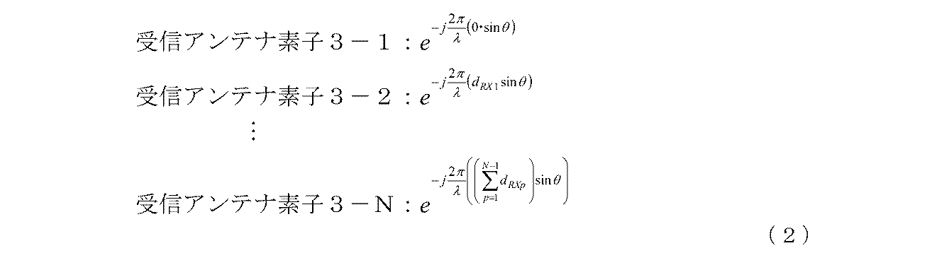 式(2)において、θはアレイアンテナ3のボアサイト方向に対する観測対象の角度である。
式(1)(2)では、送信アンテナ2-1~2-3を1つのアレイアンテナとして考えた場合のアレイアンテナのボアサイト方向と、アレイアンテナ3のボアサイト方向とが同じである例を示している。 The receiving antenna elements 3-1 to 3-N of thearray antenna 3 receive the transmitted signals (1) to (3) that have been radiated from the transmitting antennas 2-1 to 2-3 and then reflected back to the observation target. A reflected wave is received (step ST3).
Here, the difference in path from the observation target to the receiving antenna elements 3-1 to 3-N is expressed by the following equation (2).
In equation (2), θ is the angle of the observation target with respect to the boresight direction of the array antenna 3.
In Expressions (1) and (2), when the transmitting antennas 2-1 to 2-3 are considered as one array antenna, the boresight direction of the array antenna and the boresight direction of thearray antenna 3 are the same. Show.
ここで、観測対象から受信アンテナ素子3-1~3-Nに至る行路の差は、下記の式(2)のように表される。
式(1)(2)では、送信アンテナ2-1~2-3を1つのアレイアンテナとして考えた場合のアレイアンテナのボアサイト方向と、アレイアンテナ3のボアサイト方向とが同じである例を示している。 The receiving antenna elements 3-1 to 3-N of the
Here, the difference in path from the observation target to the receiving antenna elements 3-1 to 3-N is expressed by the following equation (2).
In Expressions (1) and (2), when the transmitting antennas 2-1 to 2-3 are considered as one array antenna, the boresight direction of the array antenna and the boresight direction of the
したがって、送信アンテナ2-1から観測対象に至ったのち、その観測対象から受信アンテナ素子3-1~3-Nに至る行路の差は、下記の式(3)のように表される。
 Therefore, after reaching the observation target from the transmission antenna 2-1, the difference in path from the observation target to the reception antenna elements 3-1 to 3-N is expressed by the following equation (3).
また、送信アンテナ2-2から観測対象に至ったのち、その観測対象から受信アンテナ素子3-1~3-Nに至る行路の差は、下記の式(4)のように表される。
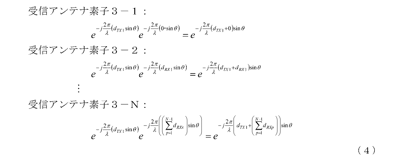 Further, the difference in the path from the observation target to the reception antenna elements 3-1 to 3-N after reaching the observation target from the transmission antenna 2-2 is expressed by the following equation (4).
さらに、送信アンテナ2-3から観測対象に至ったのち、その観測対象から受信アンテナ素子3-1~3-Nに至る行路の差は、下記の式(5)のように表される。
 式(3)~(5)において、e-j(2π/λ)(A)sinθにおける(A)は、送信アンテナ2-1~2-3と受信アンテナ素子3-1~3-Nの配置に関する部分である。
Furthermore, after reaching the observation target from the transmission antenna 2-3, the difference in the path from the observation target to the reception antenna elements 3-1 to 3-N is expressed by the following equation (5).
式(3)~(5)において、e-j(2π/λ)(A)sinθにおける(A)は、送信アンテナ2-1~2-3と受信アンテナ素子3-1~3-Nの配置に関する部分である。
Furthermore, after reaching the observation target from the transmission antenna 2-3, the difference in the path from the observation target to the reception antenna elements 3-1 to 3-N is expressed by the following equation (5).
In equations (3) to (5), (A) in e −j (2π / λ) (A) sin θ is the arrangement of the transmitting antennas 2-1 to 2-3 and the receiving antenna elements 3-1 to 3-N. It is a part about.
レプリカ生成部4は、送信信号生成処理部1-1~1-3が送信信号(1)~(3)を生成すると、その送信信号(1)~(3)のレプリカを生成し、その送信信号(1)~(3)のレプリカを相関処理部5-1~5-Nに出力する。
相互相関演算部5-1-1は、受信アンテナ素子3-1が観測対象に反射されて戻ってきた送信信号(1)~(3)の反射波を受信すると、レプリカ生成部4により生成された送信信号(1)のレプリカと受信アンテナ素子3-1の受信信号との相互相関処理を実施することで、受信アンテナ素子3-1の受信信号の中から、送信信号(1)と同一波形の信号(送信信号(1)と相関がとれている信号)を抽出し、その信号を相互相関処理後の信号としてウェイト適用部9-1-1に出力する(ステップST4)。
ここで、送信信号(1)のレプリカは、所定の長さを有する信号列であり、送信信号(1)のレプリカと受信信号との相互相関処理は、例えば、送信信号(1)のレプリカと受信信号を乗算することで、送信信号(1)のレプリカと受信信号の相関をとるマッチドフィルタなどを用いて実現することができる。 When the transmission signal generation processing units 1-1 to 1-3 generate the transmission signals (1) to (3), the replica generation unit 4 generates replicas of the transmission signals (1) to (3) and transmits the transmission signals. Replicas of the signals (1) to (3) are output to the correlation processing units 5-1 to 5-N.
The cross-correlation calculating unit 5-1-1 receives the reflected waves of the transmission signals (1) to (3) that have been reflected back to the observation target by the receiving antenna element 3-1, and is generated by the replica generating unit 4. By performing cross-correlation processing between the replica of the transmitted signal (1) and the received signal of the receiving antenna element 3-1, the same waveform as that of the transmitted signal (1) is received from the received signals of the receiving antenna element 3-1. (The signal correlated with the transmission signal (1)) is extracted, and the signal is output to the weight application unit 9-1-1 as a signal after cross-correlation processing (step ST4).
Here, the replica of the transmission signal (1) is a signal sequence having a predetermined length, and the cross-correlation process between the replica of the transmission signal (1) and the reception signal is, for example, the replica of the transmission signal (1) By multiplying the reception signal, it can be realized by using a matched filter or the like that correlates the replica of the transmission signal (1) and the reception signal.
相互相関演算部5-1-2は、レプリカ生成部4により生成された送信信号(2)のレプリカと受信アンテナ素子3-1の受信信号との相互相関処理を実施することで、受信アンテナ素子3-1の受信信号の中から、送信信号(2)と同一波形の信号を抽出し、その信号を相互相関処理後の信号としてウェイト適用部9-1-2に出力する(ステップST4)。
相互相関演算部5-1-3は、レプリカ生成部4により生成された送信信号(3)のレプリカと受信アンテナ素子3-1の受信信号との相互相関処理を実施することで、受信アンテナ素子3-1の受信信号の中から、送信信号(3)と同一波形の信号を抽出し、その信号を相互相関処理後の信号としてウェイト適用部9-1-3に出力する(ステップST4)。 The cross-correlation calculating unit 5-1-2 performs a cross-correlation process between the replica of the transmission signal (2) generated by the replica generation unit 4 and the reception signal of the reception antenna element 3-1, so that the reception antenna element A signal having the same waveform as the transmission signal (2) is extracted from the reception signal 3-1 and the signal is output to the weight application unit 9-1-2 as a signal after cross-correlation processing (step ST4).
The cross-correlation calculating unit 5-1-3 performs a cross-correlation process between the replica of the transmission signal (3) generated by the replica generation unit 4 and the reception signal of the reception antenna element 3-1, so that the reception antenna element A signal having the same waveform as the transmission signal (3) is extracted from the reception signal 3-1 and the signal is output to the weight application unit 9-1-3 as a signal after cross-correlation processing (step ST4).
相関処理部5-2の相互相関演算部5-2-1~5-2-3についても、相関処理部5-1の相互相関演算部5-1-1~5-1-3と同様の相互相関処理を実施して、相互相関処理後の信号をウェイト適用部9-2-1~9-2-3に出力する(ステップST4)。
ただし、相互相関演算部5-2-1~5-2-3は、受信アンテナ素子3-2の受信信号について相互相関処理を実施する点で、相互相関演算部5-1-1~5-1-3と相違している。 The cross-correlation calculating units 5-2-1 to 5-2-3 of the correlation processing unit 5-2 are the same as the cross-correlation calculating units 5-1-1 to 5-1-1 of the correlation processing unit 5-1. Cross-correlation processing is performed, and signals after cross-correlation processing are output to weight application units 9-2-1 to 9-2-3 (step ST4).
However, the cross-correlation calculators 5-2-1 to 5-2-3 perform the cross-correlation process on the reception signal of the reception antenna element 3-2, so that the cross-correlation calculators 5-1-1 to 5-1-2. It is different from 1-3.
相関処理部5-Nの相互相関演算部5-N-1~5-N-3についても、相関処理部5-1の相互相関演算部5-1-1~5-1-3と同様の相互相関処理を実施して、相互相関処理後の信号をウェイト適用部9-N-1~9-N-3に出力する(ステップST4)。
ただし、相互相関演算部5-N-1~5-N-3は、受信アンテナ素子3-Nの受信信号について相互相関処理を実施する点で、相互相関演算部5-1-1~5-1-3と相違している。 The cross-correlation calculation units 5-N-1 to 5-N-3 of the correlation processing unit 5-N are the same as the cross-correlation calculation units 5-1-1 to 5-1-1 of the correlation processing unit 5-1. Cross-correlation processing is performed, and the signals after cross-correlation processing are output to weight application units 9-N-1 to 9-N-3 (step ST4).
However, the cross-correlation calculators 5-N-1 to 5-N-3 perform the cross-correlation process on the reception signal of the reception antenna element 3-N, and thus the cross-correlation calculators 5-1-1 to 5-N-5. It is different from 1-3.
相関処理部5-1~5-Nが相互相関処理を実施することで、受信アンテナ素子3-1~3-Nのアンテナ開口が仮想的に広げられる。
相関処理部5-1~5-Nによる相互相関処理後のアンテナ開口の長さは、上記の式(3)~(5)からも明らかなように、受信アンテナ素子3-1を基準とすると、下記の式(6)のようになる。
相互相関処理後のアンテナ開口の長さ:
 つまり、相互相関処理後のアンテナ開口の長さは、送信アンテナ2-1と送信アンテナ2-3との間隔(dTX1+dTX2)と、受信アンテナ素子3-1と受信アンテナ素子3-Nとの間隔(dRX1+dRX2+・・・+dRX(N-1))との和に等しくなる。
When the correlation processing units 5-1 to 5-N perform cross-correlation processing, the antenna openings of the receiving antenna elements 3-1 to 3-N are virtually expanded.
つまり、相互相関処理後のアンテナ開口の長さは、送信アンテナ2-1と送信アンテナ2-3との間隔(dTX1+dTX2)と、受信アンテナ素子3-1と受信アンテナ素子3-Nとの間隔(dRX1+dRX2+・・・+dRX(N-1))との和に等しくなる。
When the correlation processing units 5-1 to 5-N perform cross-correlation processing, the antenna openings of the receiving antenna elements 3-1 to 3-N are virtually expanded.
The length of the antenna aperture after the cross-correlation processing by the correlation processing units 5-1 to 5-N is based on the reception antenna element 3-1, as is clear from the above equations (3) to (5). The following equation (6) is obtained.
Antenna aperture length after cross-correlation processing:
That is, the length of the antenna aperture after the cross-correlation processing is determined by the distance (d TX1 + d TX2 ) between the transmission antenna 2-1 and the transmission antenna 2-3, the reception antenna element 3-1 and the reception antenna element 3-N. (D RX1 + d RX2 +... + D RX (N−1) ).
相関処理部5-1~5-Nによる相互相関処理後のアンテナ開口の長さは、上記の式(3)~(5)からも明らかなように、受信アンテナ素子3-1を基準とすると、下記の式(6)のようになる。
相互相関処理後のアンテナ開口の長さ:
The length of the antenna aperture after the cross-correlation processing by the correlation processing units 5-1 to 5-N is based on the reception antenna element 3-1, as is clear from the above equations (3) to (5). The following equation (6) is obtained.
Antenna aperture length after cross-correlation processing:
図4は送信アンテナ及び受信アンテナ素子の配置と、相互相関処理後のアンテナ開口とを示す説明図である。
ただし、図4は、説明の簡単化のため、2本の送信アンテナ2-1,2-2と、5本の受信アンテナ素子3-1~3-5とが実装されている場合を示している。
また、図4は、送信アンテナ2-1と送信アンテナ2-2の間隔dTX1がdTX1=5d、受信アンテナ素子3-pと受信アンテナ素子3-(p+1)の間隔dRXpがdRXp=dである例を示している(p=1,2,3,4)。即ち、受信アンテナ素子3-1と受信アンテナ素子3-5の間隔が4dである。
また、送信アンテナ2-1と受信アンテナ素子3-1の間隔がd/2であり、送信アンテナ2-2と受信アンテナ素子3-5の間隔がd/2である。 FIG. 4 is an explanatory diagram showing the arrangement of the transmitting antenna and the receiving antenna element and the antenna aperture after the cross-correlation processing.
However, FIG. 4 shows a case where two transmission antennas 2-1 and 2-2 and five reception antenna elements 3-1 to 3-5 are mounted for the sake of simplicity. Yes.
FIG. 4 shows that the distance d TX1 between the transmission antenna 2-1 and the transmission antenna 2-2 is d TX1 = 5d, and the distance d RXp between the reception antenna element 3-p and the reception antenna element 3- (p + 1) is d RXp = An example of d is shown (p = 1, 2, 3, 4). That is, the distance between the receiving antenna element 3-1 and the receiving antenna element 3-5 is 4d.
The distance between the transmission antenna 2-1 and the reception antenna element 3-1 is d / 2, and the distance between the transmission antenna 2-2 and the reception antenna element 3-5 is d / 2.
3-1-1~3-5-1は、送信アンテナ2-1から放射された送信信号(1)のレプリカと受信アンテナ素子3-1~3-5の受信信号との相関処理に基づく、受信アンテナ素子3-1~3-5の素子配置である。
また、3-1-2~3-5-2は、送信アンテナ2-2から放射された送信信号(2)のレプリカと受信アンテナ素子3-1~3-5の受信信号との相関処理に基づく、受信アンテナ素子3-1~3-5の素子配置である。
したがって、相関処理部5-1~5-5による相互相関処理が実施されていなければ、アレイアンテナ3の開口長が4dであるが、相関処理部5-1~5-5による相互相関処理が実施されることで、上記の式(6)より、アレイアンテナ3の開口長が9dに広がっている。 3-1-1 to 3-5-1 are based on correlation processing between the replica of the transmission signal (1) radiated from the transmission antenna 2-1 and the reception signal of the reception antenna elements 3-1 to 3-5. This is an element arrangement of the receiving antenna elements 3-1 to 3-5.
Further, 3-1-2 to 3-5-2 are used for correlation processing between the replica of the transmission signal (2) radiated from the transmission antenna 2-2 and the reception signals of the reception antenna elements 3-1 to 3-5. This is an element arrangement of the receiving antenna elements 3-1 to 3-5.
Therefore, if the cross-correlation processing by the correlation processing units 5-1 to 5-5 is not performed, the aperture length of thearray antenna 3 is 4d, but the cross-correlation processing by the correlation processing units 5-1 to 5-5 is not performed. By being implemented, the opening length of the array antenna 3 extends to 9d from the above equation (6).
また、3-1-2~3-5-2は、送信アンテナ2-2から放射された送信信号(2)のレプリカと受信アンテナ素子3-1~3-5の受信信号との相関処理に基づく、受信アンテナ素子3-1~3-5の素子配置である。
したがって、相関処理部5-1~5-5による相互相関処理が実施されていなければ、アレイアンテナ3の開口長が4dであるが、相関処理部5-1~5-5による相互相関処理が実施されることで、上記の式(6)より、アレイアンテナ3の開口長が9dに広がっている。 3-1-1 to 3-5-1 are based on correlation processing between the replica of the transmission signal (1) radiated from the transmission antenna 2-1 and the reception signal of the reception antenna elements 3-1 to 3-5. This is an element arrangement of the receiving antenna elements 3-1 to 3-5.
Further, 3-1-2 to 3-5-2 are used for correlation processing between the replica of the transmission signal (2) radiated from the transmission antenna 2-2 and the reception signals of the reception antenna elements 3-1 to 3-5. This is an element arrangement of the receiving antenna elements 3-1 to 3-5.
Therefore, if the cross-correlation processing by the correlation processing units 5-1 to 5-5 is not performed, the aperture length of the
重み付け部6のウェイト決定部8は、送受アンテナ情報保持部7に保持されている送信アンテナ2-1~2-3及び受信アンテナ素子3-1~3-Nの配置を示す情報を参照して、送信アンテナ2-1と送信アンテナ2-3との間隔(dTX1+dTX2)と、受信アンテナ素子3-1と受信アンテナ素子3-Nとの間隔(dRX1+dRX2+・・・+dRX(N-1))を特定し、上記の式(6)より、相関処理部5-1~5-Nによる相互相関処理後のアンテナ開口、即ち、仮想的に広げられた受信アンテナ素子3-1~3-Nのアンテナ開口の長さを求める(ステップST5)。
ここでは、ウェイト決定部8が相関処理部5-1~5-Nによる相互相関処理後のアンテナ開口の長さを求めるようにしているが、相互相関処理後のアンテナ開口の長さが事前に特定されて、そのアンテナ開口の長さが送受アンテナ情報保持部7に保持されるように構成されていれば、ウェイト決定部8が、送受アンテナ情報保持部7に保持されているアンテナ開口の長さを読み出すようにしてもよい。 Theweight determination unit 8 of the weighting unit 6 refers to information indicating the arrangement of the transmission antennas 2-1 to 2-3 and the reception antenna elements 3-1 to 3-N held in the transmission / reception antenna information holding unit 7. , The distance between the transmitting antenna 2-1 and the transmitting antenna 2-3 (d TX1 + d TX2 ) and the distance between the receiving antenna element 3-1 and the receiving antenna element 3-N (d RX1 + d RX2 +... + D RX (N-1) ) is specified, and the antenna aperture after the cross-correlation processing by the correlation processing units 5-1 to 5-N, that is, the reception antenna element 3- The lengths of the antenna openings 1 to 3-N are obtained (step ST5).
Here, theweight determination unit 8 obtains the length of the antenna aperture after the cross-correlation processing by the correlation processing units 5-1 to 5-N. However, the length of the antenna aperture after the cross-correlation processing is determined in advance. If it is specified and the length of the antenna opening is configured to be held in the transmission / reception antenna information holding unit 7, the weight determination unit 8 has the length of the antenna opening held in the transmission / reception antenna information holding unit 7. The length may be read out.
ここでは、ウェイト決定部8が相関処理部5-1~5-Nによる相互相関処理後のアンテナ開口の長さを求めるようにしているが、相互相関処理後のアンテナ開口の長さが事前に特定されて、そのアンテナ開口の長さが送受アンテナ情報保持部7に保持されるように構成されていれば、ウェイト決定部8が、送受アンテナ情報保持部7に保持されているアンテナ開口の長さを読み出すようにしてもよい。 The
Here, the
ウェイト決定部8は、受信アンテナ素子3-1~3-Nのアンテナ開口の長さを求めると、そのアンテナ開口の長さに対応する振幅分布が、送受アンテナ情報保持部7に保持されているアンテナ指向性パターンと一致するように、相互相関演算部5-1-1~5-1-3,5-2-1~5-2-3,・・・,5-N-1~5-N-3から出力された相互相関処理後の信号に乗算するウェイトを決定する(ステップST6)。
When the weight determining unit 8 obtains the length of the antenna opening of the receiving antenna elements 3-1 to 3-N, the amplitude distribution corresponding to the length of the antenna opening is held in the transmitting / receiving antenna information holding unit 7. Cross-correlation computing units 5-1-1 to 5-1-3, 5-2-1 to 5-2-3,..., 5-N-1 to 5--5 so as to match the antenna directivity pattern A weight to be multiplied with the signal after cross-correlation processing output from N-3 is determined (step ST6).
ここでは、送受アンテナ情報保持部7に保持されているアンテナ指向性パターンが振幅分布のパターンに係るものであるものとして、アンテナ開口の長さに対応する振幅分布が送受アンテナ情報保持部7に保持されているアンテナ指向性パターンと一致するように、ウェイトを決定する例を示しているが、送受アンテナ情報保持部7に保持されているアンテナ指向性パターンが位相分布に係るものである場合には、アンテナ開口の長さに対応する位相分布が送受アンテナ情報保持部7に保持されているアンテナ指向性パターンと一致するように、ウェイトを決定するようにする。
また、送受アンテナ情報保持部7に保持されているアンテナ指向性パターンが振幅分布及び位相分布の双方に係るものであれば、アンテナ開口の長さに対応する振幅分布及び位相分布が送受アンテナ情報保持部7に保持されているアンテナ指向性パターンと一致するように、ウェイトを決定する。 Here, assuming that the antenna directivity pattern held in the transmission / reception antennainformation holding unit 7 is related to the amplitude distribution pattern, the amplitude distribution corresponding to the length of the antenna opening is held in the transmission / reception antenna information holding unit 7. In this example, the weights are determined so as to match the antenna directivity pattern that is set, but when the antenna directivity pattern held in the transmission / reception antenna information holding unit 7 is related to the phase distribution, The weights are determined so that the phase distribution corresponding to the length of the antenna aperture matches the antenna directivity pattern held in the transmission / reception antenna information holding unit 7.
If the antenna directivity pattern held in the transmission / reception antennainformation holding unit 7 relates to both the amplitude distribution and the phase distribution, the amplitude distribution and the phase distribution corresponding to the length of the antenna opening hold the transmission / reception antenna information. The weight is determined so as to match the antenna directivity pattern held in the unit 7.
また、送受アンテナ情報保持部7に保持されているアンテナ指向性パターンが振幅分布及び位相分布の双方に係るものであれば、アンテナ開口の長さに対応する振幅分布及び位相分布が送受アンテナ情報保持部7に保持されているアンテナ指向性パターンと一致するように、ウェイトを決定する。 Here, assuming that the antenna directivity pattern held in the transmission / reception antenna
If the antenna directivity pattern held in the transmission / reception antenna
一般的に所望の指向性パターンを得るには、任意の関数にしたがってアンテナ開口に対して振幅特性や位相特性を与える必要がある。
任意の関数に従う特性として、一様分布、コサイン分布、コサイン2乗分布、テイラー分布、チェビシェフ分布などが知られている。
図5は相互相関処理後のアンテナ開口に適用する任意の関数がコサイン分布であるときのウェイトの振幅分布を示す説明図である。 In general, in order to obtain a desired directivity pattern, it is necessary to give amplitude characteristics and phase characteristics to the antenna aperture according to an arbitrary function.
As characteristics according to an arbitrary function, a uniform distribution, a cosine distribution, a cosine square distribution, a Taylor distribution, a Chebyshev distribution, and the like are known.
FIG. 5 is an explanatory view showing the amplitude distribution of weights when an arbitrary function applied to the antenna aperture after cross-correlation processing is a cosine distribution.
図5は、2本の送信アンテナ2-1,2-2と、5本の受信アンテナ素子3-1~3-5とが図4のように配置されている場合を示しており、相互相関処理後のアンテナ開口における受信アンテナ素子3-1~3-5の仮想的な素子配置3-1-1~3-5-1,3-1-21~3-5-2に対してコサイン分布が適用されている。
図5の例では、相互相関処理後のアンテナ開口における受信アンテナ素子3-1~3-5の仮想的な素子配置3-1-1,3-5-2のウェイトは約0.0、素子配置3-2-1,3-4-2のウェイトは約0.34、素子配置3-3-1,3-3-2のウェイトは約0.64、素子配置3-4-1,3-2-2のウェイトは約0.87、素子配置3-5-1,3-1-2のウェイトは約0.98に決定されている。ただし、このウェイトは、あくまでも一例である。 FIG. 5 shows a case where two transmitting antennas 2-1 and 2-2 and five receiving antenna elements 3-1 to 3-5 are arranged as shown in FIG. Cosine distribution with respect to virtual element arrangements 3-1-1 to 3-5-1 and 3-1-21 to 3-5-2 of receiving antenna elements 3-1 to 3-5 at the processed antenna aperture Has been applied.
In the example of FIG. 5, the weights of the virtual element arrangements 3-1-1 and 3-5-2 of the receiving antenna elements 3-1 to 3-5 at the antenna aperture after the cross-correlation processing are about 0.0, The weight of the arrangement 3-2-1, 3-4-2 is about 0.34, the weight of the element arrangement 3-3-1, 3-3-2 is about 0.64, and the element arrangement 3-4-1, 3 The weight of -2-2 is determined to be about 0.87, and the weight of the element arrangements 3-5-1 and 3-1-2 is determined to be about 0.98. However, this weight is only an example.
重み付け部6のウェイト適用部9-1-1~9-1-3,9-2-1~9-2-3,・・・,9-N-1~9-N-3は、ウェイト決定部8がウェイトを決定すると、そのウェイトを相互相関演算部5-1-1~5-1-3,5-2-1~5-2-3,・・・,5-N-1~5-N-3から出力された相互相関処理後の信号に乗算し、ウェイトを乗算した相互相関処理後の信号を信号合成部10に出力する(ステップST7)。
例えば、各々の相互相関演算部から出力される相互相関処理後の信号が複素信号arejφr(振幅ar、位相φrの複素信号)であるとすれば、ウェイト決定部8により振幅aw、位相φwの複素信号awejφwで表されるウェイトが決定されるため、各々のウェイト適用部では、arejφr×awejφwの乗算が行われる。 The weight application units 9-1-1 to 9-1-3, 9-2-1 to 9-2-3, ..., 9-N-1 to 9-N-3 of the weighting unit 6 determine the weights. When theunit 8 determines a weight, the weights are converted into cross-correlation calculating units 5-1-1 to 5-1-3, 5-2-1 to 5-2-3,..., 5-N-1 to 5 The signal after cross-correlation processing output from −N−3 is multiplied, and the signal after cross-correlation processing multiplied by the weight is output to the signal synthesis unit 10 (step ST7).
For example, if the signal after cross-correlation processing output from each cross-correlation calculation unit is a complex signal a r e jφr (complex signal of amplitude a r and phase φ r ), theweight determination unit 8 sets the amplitude a w, since the weights are represented by a complex signal a w e jφw phase phi w is determined, in each of the weight application unit, the multiplication of a r e jφr × a w e jφw performed.
例えば、各々の相互相関演算部から出力される相互相関処理後の信号が複素信号arejφr(振幅ar、位相φrの複素信号)であるとすれば、ウェイト決定部8により振幅aw、位相φwの複素信号awejφwで表されるウェイトが決定されるため、各々のウェイト適用部では、arejφr×awejφwの乗算が行われる。 The weight application units 9-1-1 to 9-1-3, 9-2-1 to 9-2-3, ..., 9-N-1 to 9-N-3 of the weighting unit 6 determine the weights. When the
For example, if the signal after cross-correlation processing output from each cross-correlation calculation unit is a complex signal a r e jφr (complex signal of amplitude a r and phase φ r ), the
信号合成部10は、ウェイト適用部9-1-1~9-1-3,9-2-1~9-2-3,・・・,9-N-1~9-N-3が相互相関処理後の信号にウェイトを乗算すると、ウェイトが乗算されている相互相関処理後の信号を合成し、その合成信号を出力する(ステップST8)。
The signal synthesis unit 10 includes weight application units 9-1-1 to 9-1-3, 9-2-1 to 9-2-3, ..., 9-N-1 to 9-N-3. When the signal after the correlation processing is multiplied by the weight, the signal after the cross-correlation processing multiplied by the weight is combined and the combined signal is output (step ST8).
図6はこの発明の実施の形態1によるセンサ装置により得られる指向性パターンの一例を示す説明図である。
ただし、図6では、送信アンテナの本数が2、受信アンテナ素子の本数が10、受信アンテナ素子の間隔が半波長、送信アンテナの間隔が5波長の場合を示している。
また、図6では、送信アンテナ及び受信アンテナ素子が直線状に配置されており、送信アンテナと最も近い受信アンテナ素子の間隔が波長/4で、振幅特性を与える任意の関数がコサイン分布である場合を示している。 FIG. 6 is an explanatory diagram showing an example of a directivity pattern obtained by the sensor device according toEmbodiment 1 of the present invention.
However, FIG. 6 shows a case where the number of transmission antennas is 2, the number of reception antenna elements is 10, the interval between the reception antenna elements is a half wavelength, and the interval between the transmission antennas is 5 wavelengths.
Further, in FIG. 6, the transmitting antenna and the receiving antenna element are arranged in a straight line, the interval between the transmitting antenna and the receiving antenna element closest to the transmitting antenna is wavelength / 4, and an arbitrary function that gives amplitude characteristics is a cosine distribution. Is shown.
ただし、図6では、送信アンテナの本数が2、受信アンテナ素子の本数が10、受信アンテナ素子の間隔が半波長、送信アンテナの間隔が5波長の場合を示している。
また、図6では、送信アンテナ及び受信アンテナ素子が直線状に配置されており、送信アンテナと最も近い受信アンテナ素子の間隔が波長/4で、振幅特性を与える任意の関数がコサイン分布である場合を示している。 FIG. 6 is an explanatory diagram showing an example of a directivity pattern obtained by the sensor device according to
However, FIG. 6 shows a case where the number of transmission antennas is 2, the number of reception antenna elements is 10, the interval between the reception antenna elements is a half wavelength, and the interval between the transmission antennas is 5 wavelengths.
Further, in FIG. 6, the transmitting antenna and the receiving antenna element are arranged in a straight line, the interval between the transmitting antenna and the receiving antenna element closest to the transmitting antenna is wavelength / 4, and an arbitrary function that gives amplitude characteristics is a cosine distribution. Is shown.
以上で明らかなように、この実施の形態1によれば、互いに直交している複数の送信信号(1)~(3)のレプリカと受信アンテナ素子3-1(3-2,・・・,3-N)の受信信号との相互相関処理を実施して、複数の相互相関処理後の信号を出力する相関処理部5-1(5-2,・・・,5-N)と、送信アンテナ2-1~2-3及び受信アンテナ素子3-1~3-Nの配置とアンテナ指向性パターンにしたがって相関処理部5-1~5-Nから出力された複数の相互相関処理後の信号に重み付けを行う重み付け部6とを設け、信号合成部10が、重み付け部6により重み付けが行われた複数の相互相関処理後の信号を合成するように構成したので、受信アンテナ素子3-1~3-Nからなるアレイアンテナ3の開口長を仮想的に広げることができる効果を奏する。
これにより、アンテナの指向性を高めて、所望の指向性パターンを得ることが可能になる。 As apparent from the above, according to the first embodiment, replicas of a plurality of transmission signals (1) to (3) orthogonal to each other and the receiving antenna elements 3-1 (3-2,... 3-N) a correlation processing unit 5-1 (5-2,..., 5-N) that performs cross-correlation processing with the received signal and outputs a plurality of signals after cross-correlation processing; A plurality of cross-correlation processed signals output from the correlation processing units 5-1 to 5-N according to the arrangement of the antennas 2-1 to 2-3 and the receiving antenna elements 3-1 to 3-N and the antenna directivity pattern Is provided with a weighting unit 6 for weighting, and thesignal synthesis unit 10 is configured to synthesize a plurality of signals after the cross-correlation processing weighted by the weighting unit 6. The aperture length of the 3-N array antenna 3 is virtually expanded. An effect that can bet.
Thereby, the directivity of the antenna can be increased and a desired directivity pattern can be obtained.
これにより、アンテナの指向性を高めて、所望の指向性パターンを得ることが可能になる。 As apparent from the above, according to the first embodiment, replicas of a plurality of transmission signals (1) to (3) orthogonal to each other and the receiving antenna elements 3-1 (3-2,... 3-N) a correlation processing unit 5-1 (5-2,..., 5-N) that performs cross-correlation processing with the received signal and outputs a plurality of signals after cross-correlation processing; A plurality of cross-correlation processed signals output from the correlation processing units 5-1 to 5-N according to the arrangement of the antennas 2-1 to 2-3 and the receiving antenna elements 3-1 to 3-N and the antenna directivity pattern Is provided with a weighting unit 6 for weighting, and the
Thereby, the directivity of the antenna can be increased and a desired directivity pattern can be obtained.
この実施の形態1では、送信アンテナ2-1~2-3及び受信アンテナ素子3-1~3-Nが1次元配置である例を示しているが、複数の送信アンテナ及び複数の受信アンテナ素子を2次元に配置するものであってもよい。
この実施の形態1では、1つの指向性パターンを得る例を示しているが、異なる複数の指向性パターンを得るようにしてもよい。この場合、ウェイト適用部9-1-1~9-1-3,9-2-1~9-2-3,9-N-1~9-N-3及び信号合成部10を各々の指向性パターン毎に実装するようにすればよい。 In the first embodiment, an example in which the transmission antennas 2-1 to 2-3 and the reception antenna elements 3-1 to 3-N are one-dimensionally arranged is shown. However, a plurality of transmission antennas and a plurality of reception antenna elements are shown. May be arranged two-dimensionally.
In the first embodiment, an example of obtaining one directivity pattern is shown, but a plurality of different directivity patterns may be obtained. In this case, the weight application units 9-1-1 to 9-1-3, 9-2-1 to 9-2-3, 9-N-1 to 9-N-3 and thesignal synthesis unit 10 are directed to the respective directions. It may be implemented for each sex pattern.
この実施の形態1では、1つの指向性パターンを得る例を示しているが、異なる複数の指向性パターンを得るようにしてもよい。この場合、ウェイト適用部9-1-1~9-1-3,9-2-1~9-2-3,9-N-1~9-N-3及び信号合成部10を各々の指向性パターン毎に実装するようにすればよい。 In the first embodiment, an example in which the transmission antennas 2-1 to 2-3 and the reception antenna elements 3-1 to 3-N are one-dimensionally arranged is shown. However, a plurality of transmission antennas and a plurality of reception antenna elements are shown. May be arranged two-dimensionally.
In the first embodiment, an example of obtaining one directivity pattern is shown, but a plurality of different directivity patterns may be obtained. In this case, the weight application units 9-1-1 to 9-1-3, 9-2-1 to 9-2-3, 9-N-1 to 9-N-3 and the
実施の形態2.
上記実施の形態1では、2本の送信アンテナ2-1,2-2と、5本の受信アンテナ素子3-1~3-5とが実装されている場合の例を図4に示している。
図4の例では、受信アンテナ素子3-1~3-5の中に、送信アンテナ2-1,2-2の位置と重なる位置に配置されている受信アンテナ素子は存在していないが、受信アンテナ素子3-1~3-5の中に、送信アンテナ2-1,2-2の位置と重なる位置に配置されている受信アンテナ素子が存在するものであってもよい。
この実施の形態2でも、センサ装置の構成は、上記実施の形態1における図1の構成と同様である。Embodiment 2. FIG.
In the first embodiment, an example in which two transmitting antennas 2-1 and 2-2 and five receiving antenna elements 3-1 to 3-5 are mounted is shown in FIG. .
In the example of FIG. 4, the receiving antenna elements 3-1 to 3-5 do not have the receiving antenna elements arranged at the positions overlapping with the transmitting antennas 2-1 and 2-2. Among the antenna elements 3-1 to 3-5, there may be a receiving antenna element arranged at a position overlapping the positions of the transmission antennas 2-1 and 2-2.
Also in the second embodiment, the configuration of the sensor device is the same as the configuration of FIG. 1 in the first embodiment.
上記実施の形態1では、2本の送信アンテナ2-1,2-2と、5本の受信アンテナ素子3-1~3-5とが実装されている場合の例を図4に示している。
図4の例では、受信アンテナ素子3-1~3-5の中に、送信アンテナ2-1,2-2の位置と重なる位置に配置されている受信アンテナ素子は存在していないが、受信アンテナ素子3-1~3-5の中に、送信アンテナ2-1,2-2の位置と重なる位置に配置されている受信アンテナ素子が存在するものであってもよい。
この実施の形態2でも、センサ装置の構成は、上記実施の形態1における図1の構成と同様である。
In the first embodiment, an example in which two transmitting antennas 2-1 and 2-2 and five receiving antenna elements 3-1 to 3-5 are mounted is shown in FIG. .
In the example of FIG. 4, the receiving antenna elements 3-1 to 3-5 do not have the receiving antenna elements arranged at the positions overlapping with the transmitting antennas 2-1 and 2-2. Among the antenna elements 3-1 to 3-5, there may be a receiving antenna element arranged at a position overlapping the positions of the transmission antennas 2-1 and 2-2.
Also in the second embodiment, the configuration of the sensor device is the same as the configuration of FIG. 1 in the first embodiment.
図7は送信アンテナ及び受信アンテナ素子の配置と、相互相関処理後のアンテナ開口とを示す説明図である。
図7は、説明の簡単化のため、2本の送信アンテナ2-1,2-2と、5本の受信アンテナ素子3-1~3-5とが実装されている場合を示している。
また、図7は、送信アンテナ2-1と送信アンテナ2-2の間隔dTX1がdTX1=3d、受信アンテナ素子3-pと受信アンテナ素子3-(p+1)の間隔dRXpがdRXp=dである例を示している(p=1,2,3,4)。即ち、受信アンテナ素子3-1と受信アンテナ素子3-5の間隔が4dである。
また、送信アンテナ2-1と受信アンテナ素子3-1の並び方向の位置が同じであり、送信アンテナ2-2と受信アンテナ素子3-3の並び方向の位置が同じである。 FIG. 7 is an explanatory diagram showing the arrangement of the transmitting antenna and the receiving antenna element and the antenna aperture after the cross-correlation processing.
FIG. 7 shows a case where two transmission antennas 2-1 and 2-2 and five reception antenna elements 3-1 to 3-5 are mounted for the sake of simplicity.
FIG. 7 shows that the distance d TX1 between the transmitting antenna 2-1 and the transmitting antenna 2-2 is d TX1 = 3d, and the distance d RXp between the receiving antenna element 3-p and the receiving antenna element 3- (p + 1) is d RXp = An example of d is shown (p = 1, 2, 3, 4). That is, the distance between the receiving antenna element 3-1 and the receiving antenna element 3-5 is 4d.
Further, the position of the transmitting antenna 2-1 and the receiving antenna element 3-1 in the alignment direction is the same, and the position of the transmitting antenna 2-2 and the receiving antenna element 3-3 in the alignment direction are the same.
3-1-1~3-5-1は、送信アンテナ2-1から放射された送信信号(1)のレプリカと受信アンテナ素子3-1~3-5の受信信号との相関処理に基づく、受信アンテナ素子3-1~3-5の素子配置である。
また、3-1-2~3-5-2は、送信アンテナ2-2から放射された送信信号(2)のレプリカと受信アンテナ素子3-1~3-5の受信信号との相関処理に基づく、受信アンテナ素子3-1~3-5の素子配置である。
したがって、相関処理部5-1~5-Nによる相互相関処理が実施されていなければ、アレイアンテナ3の開口長が4dであるが、相関処理部5-1~5-Nによる相互相関処理が実施されることで、上記の式(6)より、アレイアンテナ3の開口長が7dに広がっている。
ただし、この実施の形態2では、送信アンテナ2-1と受信アンテナ素子3-1の並び方向の位置が同じであり、また、送信アンテナ2-2と受信アンテナ素子3-3の並び方向の位置が同じである。このため、素子配置3-4-1と素子配置3-1-2が重なり、また、素子配置3-5-1と素子配置3-2-2が重なっている。 3-1-1 to 3-5-1 are based on correlation processing between the replica of the transmission signal (1) radiated from the transmission antenna 2-1 and the reception signal of the reception antenna elements 3-1 to 3-5. This is an element arrangement of the receiving antenna elements 3-1 to 3-5.
Further, 3-1-2 to 3-5-2 are used for correlation processing between the replica of the transmission signal (2) radiated from the transmission antenna 2-2 and the reception signals of the reception antenna elements 3-1 to 3-5. This is an element arrangement of the receiving antenna elements 3-1 to 3-5.
Therefore, if the cross-correlation processing by the correlation processing units 5-1 to 5-N is not performed, the aperture length of thearray antenna 3 is 4d, but the cross-correlation processing by the correlation processing units 5-1 to 5-N is not performed. As a result, the opening length of the array antenna 3 is expanded to 7d from the above equation (6).
However, in the second embodiment, the positions of the transmitting antenna 2-1 and the receiving antenna element 3-1 in the alignment direction are the same, and the positions of the transmitting antenna 2-2 and the receiving antenna element 3-3 in the alignment direction are the same. Are the same. Therefore, the element arrangement 3-4-1 and the element arrangement 3-1-2 overlap, and the element arrangement 3-5-1 and the element arrangement 3-2-2 overlap.
また、3-1-2~3-5-2は、送信アンテナ2-2から放射された送信信号(2)のレプリカと受信アンテナ素子3-1~3-5の受信信号との相関処理に基づく、受信アンテナ素子3-1~3-5の素子配置である。
したがって、相関処理部5-1~5-Nによる相互相関処理が実施されていなければ、アレイアンテナ3の開口長が4dであるが、相関処理部5-1~5-Nによる相互相関処理が実施されることで、上記の式(6)より、アレイアンテナ3の開口長が7dに広がっている。
ただし、この実施の形態2では、送信アンテナ2-1と受信アンテナ素子3-1の並び方向の位置が同じであり、また、送信アンテナ2-2と受信アンテナ素子3-3の並び方向の位置が同じである。このため、素子配置3-4-1と素子配置3-1-2が重なり、また、素子配置3-5-1と素子配置3-2-2が重なっている。 3-1-1 to 3-5-1 are based on correlation processing between the replica of the transmission signal (1) radiated from the transmission antenna 2-1 and the reception signal of the reception antenna elements 3-1 to 3-5. This is an element arrangement of the receiving antenna elements 3-1 to 3-5.
Further, 3-1-2 to 3-5-2 are used for correlation processing between the replica of the transmission signal (2) radiated from the transmission antenna 2-2 and the reception signals of the reception antenna elements 3-1 to 3-5. This is an element arrangement of the receiving antenna elements 3-1 to 3-5.
Therefore, if the cross-correlation processing by the correlation processing units 5-1 to 5-N is not performed, the aperture length of the
However, in the second embodiment, the positions of the transmitting antenna 2-1 and the receiving antenna element 3-1 in the alignment direction are the same, and the positions of the transmitting antenna 2-2 and the receiving antenna element 3-3 in the alignment direction are the same. Are the same. Therefore, the element arrangement 3-4-1 and the element arrangement 3-1-2 overlap, and the element arrangement 3-5-1 and the element arrangement 3-2-2 overlap.
図8は相互相関処理後のアンテナ開口に適用する任意の関数がコサイン分布であるときのウェイトの振幅分布を示す説明図である。
重み付け部6のウェイト決定部8は、上記実施の形態1と同様に、相互相関処理後のアンテナ開口の長さを求め、そのアンテナ開口の長さに対応する振幅分布が、送受アンテナ情報保持部7に保持されているアンテナ指向性パターンと一致するように、相互相関処理後の信号に乗算するウェイトを決定する。
ただし、図7のように、素子配置3-4-1,3-5-1と素子配置3-1-2,3-2-2が重なっている場合、上記実施の形態1と同様にウェイトを決定すると、図8(a)に示すように、重なっている素子配置において、2つの相互相関処理後の信号が重なるため、信号合成部10への重なった位置の入力信号が所望の振幅の2倍になってしまう。 FIG. 8 is an explanatory diagram showing the amplitude distribution of weights when an arbitrary function applied to the antenna aperture after cross-correlation processing is a cosine distribution.
Theweight determination unit 8 of the weighting unit 6 obtains the length of the antenna opening after the cross-correlation processing, as in the first embodiment, and the amplitude distribution corresponding to the length of the antenna opening is the transmission / reception antenna information holding unit. 7 is determined so as to match the antenna directivity pattern held in FIG.
However, as shown in FIG. 7, when the element arrangements 3-4-1, 3-5-1 and the element arrangements 3-1-2, 3-2-2 overlap, the weights are the same as in the first embodiment. 8A, since the signals after the two cross-correlation processes overlap in the overlapping element arrangement as shown in FIG. 8A, the input signal at the overlapped position to thesignal synthesizer 10 has a desired amplitude. It will double.
重み付け部6のウェイト決定部8は、上記実施の形態1と同様に、相互相関処理後のアンテナ開口の長さを求め、そのアンテナ開口の長さに対応する振幅分布が、送受アンテナ情報保持部7に保持されているアンテナ指向性パターンと一致するように、相互相関処理後の信号に乗算するウェイトを決定する。
ただし、図7のように、素子配置3-4-1,3-5-1と素子配置3-1-2,3-2-2が重なっている場合、上記実施の形態1と同様にウェイトを決定すると、図8(a)に示すように、重なっている素子配置において、2つの相互相関処理後の信号が重なるため、信号合成部10への重なった位置の入力信号が所望の振幅の2倍になってしまう。 FIG. 8 is an explanatory diagram showing the amplitude distribution of weights when an arbitrary function applied to the antenna aperture after cross-correlation processing is a cosine distribution.
The
However, as shown in FIG. 7, when the element arrangements 3-4-1, 3-5-1 and the element arrangements 3-1-2, 3-2-2 overlap, the weights are the same as in the first embodiment. 8A, since the signals after the two cross-correlation processes overlap in the overlapping element arrangement as shown in FIG. 8A, the input signal at the overlapped position to the
そこで、この実施の形態2では、重み付け部6のウェイト決定部8は、素子配置3-4-1,3-5-1と素子配置3-1-2,3-2-2が重なる場合、素子配置3-4-1,3-5-1,3-1-2,3-2-2に対応する相互相関演算部及びウェイト適用部が、それぞれ相互相関演算部5-4-1,5-5-1,5-1-2,5-2-2、ウェイト適用部9-4-1,9-5-1,9-1-2,9-2-2であるとすると、相互相関演算部5-1-1~5-3-1,5-3-2~5-5-2から出力される信号に乗算するウェイトについては、上記実施の形態1と同様に決定する。
一方、相互相関演算部5-4-1,5-5-1,5-1-2,5-2-2から出力される信号に乗算するウェイトについては、上記実施の形態1と同様に決定したウェイトの2分の1に決定する。 Therefore, in the second embodiment, theweight determining unit 8 of the weighting unit 6 is configured so that the element arrangement 3-4-1, 3-5-1 and the element arrangement 3-1-2, 3-2-2 overlap. The cross-correlation calculation unit and the weight application unit corresponding to the element arrangement 3-4-1, 3-5-1, 3-1-2, 3-2-2 are respectively cross-correlation calculation units 5-4-1, 5 -5-1, 5-1-2, 5-2-2, and weight application units 9-4-1, 9-5-1, 9-1-2, 9-2-2. Weights to be multiplied with signals output from the arithmetic units 5-1-1 to 5-3-1 and 5-3-2 to 5-5-2 are determined in the same manner as in the first embodiment.
On the other hand, the weights to be multiplied with the signals output from the cross-correlation computing units 5-4-1, 5-5-1, 5-1-2, and 5-2-2 are determined in the same manner as in the first embodiment. Is determined to be half of the weight.
一方、相互相関演算部5-4-1,5-5-1,5-1-2,5-2-2から出力される信号に乗算するウェイトについては、上記実施の形態1と同様に決定したウェイトの2分の1に決定する。 Therefore, in the second embodiment, the
On the other hand, the weights to be multiplied with the signals output from the cross-correlation computing units 5-4-1, 5-5-1, 5-1-2, and 5-2-2 are determined in the same manner as in the first embodiment. Is determined to be half of the weight.
重み付け部6のウェイト適用部9-1-1~9-5-1,9-1-2~9-5-2は、ウェイト決定部8がウェイトを決定すると、そのウェイトを相互相関演算部5-1-1~5-5-1,5-1-2~5-5-2から出力された相互相関処理後の信号に乗算し、ウェイトを乗算した相互相関処理後の信号を信号合成部10に出力する。
信号合成部10は、ウェイト適用部9-1-1~9-5-1,9-1-2~9-5-2が相互相関処理後の信号にウェイトを乗算すると、ウェイトが乗算されている相互相関処理後の信号を合成し、その合成信号を出力する。 When theweight determining unit 8 determines a weight, the weight applying units 9-1-1 to 9-5-1 and 9-1-2 to 9-5-2 of the weighting unit 6 convert the weights into the cross-correlation calculating unit 5 -1-1 to 5-5-1 and 5-1-2 to 5-5-2, the signal after cross-correlation processing is multiplied and the signal after cross-correlation processing multiplied by the weight is signal synthesizer 10 is output.
When the weight applying units 9-1-1 to 9-5-1 and 9-1-2 to 9-5-2 multiply the signals after cross-correlation processing by the weights, thesignal combining unit 10 multiplies the weights. The signals after cross-correlation processing are combined and the combined signal is output.
信号合成部10は、ウェイト適用部9-1-1~9-5-1,9-1-2~9-5-2が相互相関処理後の信号にウェイトを乗算すると、ウェイトが乗算されている相互相関処理後の信号を合成し、その合成信号を出力する。 When the
When the weight applying units 9-1-1 to 9-5-1 and 9-1-2 to 9-5-2 multiply the signals after cross-correlation processing by the weights, the
このとき、相互相関演算部5-4-1,5-5-1,5-1-2,5-2-2から出力される信号に乗算するウェイトが2分の1に決定されているため、重なり合っている素子配置3-4-1と素子配置3-1-2では、上記実施の形態1と比べて、ウェイト適用部9-4-1,9-1-2から出力される相互相関処理後の信号が2分の1になる。
また、重なり合っている素子配置3-5-1と素子配置3-2-2では、上記実施の形態1と比べて、ウェイト適用部9-5-1,9-2-2から出力される相互相関処理後の信号が2分の1になる。
これにより、重なっている素子配置においても、図8(b)に示すように、送受アンテナ情報保持部7に保持されている所望のアンテナ指向性パターンと振幅分布が一致するようになる。 At this time, the weight for multiplying the signal output from the cross-correlation computing units 5-4-1, 5-5-1, 5-1-2, and 5-2-2 is determined to be a half. In the overlapping element arrangement 3-4-1 and element arrangement 3-1-2, the cross-correlations output from the weight application units 9-4-1 and 9-1-2 are compared with those in the first embodiment. The processed signal is halved.
Further, in the overlapping element arrangement 3-5-1 and element arrangement 3-2-2, as compared with the first embodiment, the mutual outputs output from the weight application units 9-5-1 and 9-2-2. The signal after the correlation processing is halved.
As a result, even in the overlapping element arrangement, as shown in FIG. 8B, the desired antenna directivity pattern held in the transmission / reception antennainformation holding unit 7 matches the amplitude distribution.
また、重なり合っている素子配置3-5-1と素子配置3-2-2では、上記実施の形態1と比べて、ウェイト適用部9-5-1,9-2-2から出力される相互相関処理後の信号が2分の1になる。
これにより、重なっている素子配置においても、図8(b)に示すように、送受アンテナ情報保持部7に保持されている所望のアンテナ指向性パターンと振幅分布が一致するようになる。 At this time, the weight for multiplying the signal output from the cross-correlation computing units 5-4-1, 5-5-1, 5-1-2, and 5-2-2 is determined to be a half. In the overlapping element arrangement 3-4-1 and element arrangement 3-1-2, the cross-correlations output from the weight application units 9-4-1 and 9-1-2 are compared with those in the first embodiment. The processed signal is halved.
Further, in the overlapping element arrangement 3-5-1 and element arrangement 3-2-2, as compared with the first embodiment, the mutual outputs output from the weight application units 9-5-1 and 9-2-2. The signal after the correlation processing is halved.
As a result, even in the overlapping element arrangement, as shown in FIG. 8B, the desired antenna directivity pattern held in the transmission / reception antenna
この実施の形態2では、素子配置が重なっている位置のウェイトを、上記実施の形態1と同様に決定したウェイトの2分の1に決定するものを示したが、例えば、素子配置が重なっている位置のウェイトについては上記実施の形態1と同様に決定するとともに、素子配置が重なっていない位置のウェイトを、上記実施の形態1と同様に決定したウェイトの2倍に決定したのち、全体の利得が1になるように各素子配置の振幅を調整するようにしてもよい。
なお、この実施の形態2では、素子配置が重なっている位置の個数が2個であるため、ウェイトの2分の1に決定しているが、素子配置が重なっている位置の個数がM個であれば、ウェイトのM分の1に決定すればよい。 In the second embodiment, the weight at the position where the element arrangements overlap is determined to be half of the weight determined in the same manner as in the first embodiment. For example, the element arrangements overlap. The weight at a certain position is determined in the same manner as in the first embodiment, and the weight at a position where the element arrangement is not overlapped is determined to be twice the weight determined in the same manner as in the first embodiment. You may make it adjust the amplitude of each element arrangement | positioning so that a gain may be set to one.
In the second embodiment, since the number of positions where the element arrangements overlap is two, the number of positions where the element arrangements overlap is determined to be one half of the weight. If so, it may be determined to be 1 / M of the weight.
以上で明らかなように、この実施の形態2によれば、受信アンテナ素子3-1~3-5の中に、送信アンテナ2-1,2-2の位置と重なる位置に配置されている受信アンテナ素子が存在する場合であっても、上記実施の形態1と同様に、受信アンテナ素子3-1~3-5からなるアレイアンテナ3の開口長を仮想的に広げることができる効果を奏する。
これにより、アンテナの指向性を高めて、所望の指向性パターンを得ることが可能になる。 As is apparent from the above, according to the second embodiment, the reception antenna elements 3-1 to 3-5 that are disposed at positions overlapping the positions of the transmission antennas 2-1 and 2-2 are arranged. Even when there is an antenna element, the aperture length of thearray antenna 3 composed of the receiving antenna elements 3-1 to 3-5 can be virtually widened as in the first embodiment.
Thereby, the directivity of the antenna can be increased and a desired directivity pattern can be obtained.
これにより、アンテナの指向性を高めて、所望の指向性パターンを得ることが可能になる。 As is apparent from the above, according to the second embodiment, the reception antenna elements 3-1 to 3-5 that are disposed at positions overlapping the positions of the transmission antennas 2-1 and 2-2 are arranged. Even when there is an antenna element, the aperture length of the
Thereby, the directivity of the antenna can be increased and a desired directivity pattern can be obtained.
実施の形態3.
図9はこの発明の実施の形態3によるセンサ装置を示す構成図であり、図9において、図1と同一符号は同一または相当部分を示すので説明を省略する。
指向性切換部31はタイミング制御部32の制御によって送信アンテナ2-1~2-3の指向性を切り換える装置である。
なお、指向性切換部31は、送信アンテナ2-1~2-3の向きを物理的に切り換えるモータなどの駆動装置で構成されていてもよいし、送信アンテナ2-1~2-3から放射される送信信号(1)~(3)の向きを光学的に切り換える光学素子で構成されていてもよいし、送信アンテナ2-1~2-3が複数の素子からなり、送信アンテナ部2が送信アンテナ2-1~2-3をサブアレイとする場合には電気的に切り換えてもよい。
タイミング制御部32は指向性切換部31による指向性の切り換えタイミングを制御する制御回路である。Embodiment 3 FIG.
9 is a block diagram showing a sensor device according toEmbodiment 3 of the present invention. In FIG. 9, the same reference numerals as those in FIG.
Thedirectivity switching unit 31 is a device that switches the directivities of the transmission antennas 2-1 to 2-3 under the control of the timing control unit 32.
Thedirectivity switching unit 31 may be configured by a driving device such as a motor that physically switches the direction of the transmission antennas 2-1 to 2-3, or the radiation from the transmission antennas 2-1 to 2-3. The transmission signals (1) to (3) may be configured to be optically switched, and the transmission antennas 2-1 to 2-3 are composed of a plurality of elements, and the transmission antenna unit 2 When the transmitting antennas 2-1 to 2-3 are subarrays, they may be switched electrically.
Thetiming control unit 32 is a control circuit that controls the directivity switching timing by the directivity switching unit 31.
図9はこの発明の実施の形態3によるセンサ装置を示す構成図であり、図9において、図1と同一符号は同一または相当部分を示すので説明を省略する。
指向性切換部31はタイミング制御部32の制御によって送信アンテナ2-1~2-3の指向性を切り換える装置である。
なお、指向性切換部31は、送信アンテナ2-1~2-3の向きを物理的に切り換えるモータなどの駆動装置で構成されていてもよいし、送信アンテナ2-1~2-3から放射される送信信号(1)~(3)の向きを光学的に切り換える光学素子で構成されていてもよいし、送信アンテナ2-1~2-3が複数の素子からなり、送信アンテナ部2が送信アンテナ2-1~2-3をサブアレイとする場合には電気的に切り換えてもよい。
タイミング制御部32は指向性切換部31による指向性の切り換えタイミングを制御する制御回路である。
9 is a block diagram showing a sensor device according to
The
The
The
次に動作について説明する。
指向性切換部31及びタイミング制御部32を実装している点以外は、上記実施の形態1,2と同様であるため、ここでは指向性切換部31及びタイミング制御部32の動作についてだけ説明する。 Next, the operation will be described.
Except for the fact that thedirectivity switching unit 31 and the timing control unit 32 are mounted, the operation is the same as in the first and second embodiments. Therefore, only the operations of the directivity switching unit 31 and the timing control unit 32 will be described here. .
指向性切換部31及びタイミング制御部32を実装している点以外は、上記実施の形態1,2と同様であるため、ここでは指向性切換部31及びタイミング制御部32の動作についてだけ説明する。 Next, the operation will be described.
Except for the fact that the
上記実施の形態1,2では、送信アンテナ2-1~2-3が互いに直交している送信信号(1)~(3)を空間に放射するものを示しているが、例えば、図1のセンサ装置を搭載している衛星等が移動している場合や、観測対象が移動している場合、それらの移動に伴うドップラーシフトが生じるため、送信アンテナ2-1~2-3から観測対象に至る行路差等の影響で、受信アンテナ素子3-1~3-Nの受信信号の直交性が若干崩れる場合がある。
この実施の形態3では、受信アンテナ素子3-1~3-Nの受信信号の直交性を維持するため、指向性切換部31及びタイミング制御部32を実装している。 In the first and second embodiments, the transmission antennas 2-1 to 2-3 radiate transmission signals (1) to (3) that are orthogonal to each other. For example, FIG. When a satellite equipped with a sensor device is moving, or when the observation target is moving, Doppler shift occurs due to the movement, so the transmission antennas 2-1 to 2-3 change the observation target. The orthogonality of the received signals of the receiving antenna elements 3-1 to 3-N may be slightly disrupted due to the influence of the path difference to reach.
In the third embodiment, thedirectivity switching unit 31 and the timing control unit 32 are mounted in order to maintain the orthogonality of the received signals of the receiving antenna elements 3-1 to 3-N.
この実施の形態3では、受信アンテナ素子3-1~3-Nの受信信号の直交性を維持するため、指向性切換部31及びタイミング制御部32を実装している。 In the first and second embodiments, the transmission antennas 2-1 to 2-3 radiate transmission signals (1) to (3) that are orthogonal to each other. For example, FIG. When a satellite equipped with a sensor device is moving, or when the observation target is moving, Doppler shift occurs due to the movement, so the transmission antennas 2-1 to 2-3 change the observation target. The orthogonality of the received signals of the receiving antenna elements 3-1 to 3-N may be slightly disrupted due to the influence of the path difference to reach.
In the third embodiment, the
タイミング制御部32は、指向性切換部31による指向性の切り換えタイミングを制御する。
即ち、タイミング制御部32は、送信アンテナ2-1~2-3の指向性を切り換えるタイミングになると、指向性の切換指令を指向性切換部31及び送信信号生成処理部1-1~1-3に出力する。
指向性切換部31は、タイミング制御部32から指向性の切換指令を受けると、送信アンテナ2-1~2-3の指向性を切り換える動作を行う。 Thetiming control unit 32 controls the directivity switching timing by the directivity switching unit 31.
That is, thetiming control unit 32 sends a directivity switching command to the directivity switching unit 31 and the transmission signal generation processing units 1-1 to 1-3 at the timing for switching the directivities of the transmission antennas 2-1 to 2-3. Output to.
When thedirectivity switching unit 31 receives a directivity switching command from the timing control unit 32, the directivity switching unit 31 performs an operation of switching the directivities of the transmission antennas 2-1 to 2-3.
即ち、タイミング制御部32は、送信アンテナ2-1~2-3の指向性を切り換えるタイミングになると、指向性の切換指令を指向性切換部31及び送信信号生成処理部1-1~1-3に出力する。
指向性切換部31は、タイミング制御部32から指向性の切換指令を受けると、送信アンテナ2-1~2-3の指向性を切り換える動作を行う。 The
That is, the
When the
送信信号生成処理部1-1~1-3は、上記実施の形態1,2と同様に、互いに直交している送信信号(1)~(3)を生成して、その送信信号(1)~(3)を送信アンテナ2-1~2-3に出力するが、指向性切換部31により送信アンテナ2-1~2-3の指向性が切り換えられているタイミングでは、送信信号(1)~(3)を送信アンテナ2-1~2-3に出力しないようにするため、タイミング制御部32から指向性の切換指令を受けると、所定の時間中、送信アンテナ2-1~2-3に対する送信信号(1)~(3)の出力を停止する。
Similarly to the first and second embodiments, the transmission signal generation processing units 1-1 to 1-3 generate transmission signals (1) to (3) that are orthogonal to each other, and transmit the transmission signal (1). To (3) are output to the transmission antennas 2-1 to 2-3, but at the timing when the directivity of the transmission antennas 2-1 to 2-3 is switched by the directivity switching unit 31, the transmission signal (1) When (3) is not output to the transmission antennas 2-1 to 2-3, upon receiving a directivity switching command from the timing control unit 32, the transmission antennas 2-1 to 2-3 are transmitted for a predetermined time. Stops outputting the transmission signals (1) to (3).
ここで、図10は送信アンテナ2-1~2-3の指向性パターンの一例を示す説明図である。
この実施の形態3では、図10に示すように、3つの指向性パターン(1)~(3)が用意され、送信アンテナ2-1~2-3に対する指向性パターン(1)~(3)の割り当てが順番に切り換えられる例を説明する。
指向性パターン(1)~(3)は、最も利得が高いメインローブ同士が互いに重ならない指向性パターンであるものとする。
以下、指向性切換部31による指向性パターン(1)~(3)の切り換え例を具体的に説明する。
ただし、この実施の形態3は、指向性パターン(1)~(3)が示す方向のうち、いずれか1つの方向にだけ観測対象が存在している場合に適用されるものとする。 Here, FIG. 10 is an explanatory diagram showing an example of the directivity pattern of the transmission antennas 2-1 to 2-3.
In the third embodiment, as shown in FIG. 10, three directivity patterns (1) to (3) are prepared, and the directivity patterns (1) to (3) for the transmission antennas 2-1 to 2-3 are prepared. An example will be described in which the assignments are switched in order.
The directivity patterns (1) to (3) are directivity patterns in which main lobes having the highest gain do not overlap each other.
Hereinafter, a switching example of the directivity patterns (1) to (3) by thedirectivity switching unit 31 will be specifically described.
However, the third embodiment is applied when the observation target exists only in any one of the directions indicated by the directivity patterns (1) to (3).
この実施の形態3では、図10に示すように、3つの指向性パターン(1)~(3)が用意され、送信アンテナ2-1~2-3に対する指向性パターン(1)~(3)の割り当てが順番に切り換えられる例を説明する。
指向性パターン(1)~(3)は、最も利得が高いメインローブ同士が互いに重ならない指向性パターンであるものとする。
以下、指向性切換部31による指向性パターン(1)~(3)の切り換え例を具体的に説明する。
ただし、この実施の形態3は、指向性パターン(1)~(3)が示す方向のうち、いずれか1つの方向にだけ観測対象が存在している場合に適用されるものとする。 Here, FIG. 10 is an explanatory diagram showing an example of the directivity pattern of the transmission antennas 2-1 to 2-3.
In the third embodiment, as shown in FIG. 10, three directivity patterns (1) to (3) are prepared, and the directivity patterns (1) to (3) for the transmission antennas 2-1 to 2-3 are prepared. An example will be described in which the assignments are switched in order.
The directivity patterns (1) to (3) are directivity patterns in which main lobes having the highest gain do not overlap each other.
Hereinafter, a switching example of the directivity patterns (1) to (3) by the
However, the third embodiment is applied when the observation target exists only in any one of the directions indicated by the directivity patterns (1) to (3).
指向性切換部31は、タイミング制御部32から出力された最初の切換指令を受けると、送信アンテナ2-1~2-3に対して、指向性パターン(1)~(3)を下記のように割り当てる。
指向性パターン(1)→送信アンテナ2-1
指向性パターン(2)→送信アンテナ2-2
指向性パターン(3)→送信アンテナ2-3 When thedirectivity switching unit 31 receives the first switching command output from the timing control unit 32, the directivity patterns (1) to (3) are transmitted to the transmitting antennas 2-1 to 2-3 as follows. Assign to.
Directivity pattern (1) → Transmitting antenna 2-1
Directivity pattern (2) → Transmitting antenna 2-2
Directivity pattern (3) → Transmitting antenna 2-3
指向性パターン(1)→送信アンテナ2-1
指向性パターン(2)→送信アンテナ2-2
指向性パターン(3)→送信アンテナ2-3 When the
Directivity pattern (1) → Transmitting antenna 2-1
Directivity pattern (2) → Transmitting antenna 2-2
Directivity pattern (3) → Transmitting antenna 2-3
指向性切換部31は、タイミング制御部32から出力された次の切換指令を受けると、送信アンテナ2-1~2-3に対して、指向性パターン(1)~(3)を下記のように割り当てる。
指向性パターン(2)→送信アンテナ2-1
指向性パターン(3)→送信アンテナ2-2
指向性パターン(1)→送信アンテナ2-3 When thedirectivity switching unit 31 receives the next switching command output from the timing control unit 32, the directivity patterns (1) to (3) are transmitted to the transmitting antennas 2-1 to 2-3 as follows. Assign to.
Directivity pattern (2) → Transmitting antenna 2-1
Directivity pattern (3) → Transmitting antenna 2-2
Directivity pattern (1) → Transmitting antenna 2-3
指向性パターン(2)→送信アンテナ2-1
指向性パターン(3)→送信アンテナ2-2
指向性パターン(1)→送信アンテナ2-3 When the
Directivity pattern (2) → Transmitting antenna 2-1
Directivity pattern (3) → Transmitting antenna 2-2
Directivity pattern (1) → Transmitting antenna 2-3
指向性切換部31は、タイミング制御部32から出力された次の切換指令を受けると、送信アンテナ2-1~2-3に対して、指向性パターン(1)~(3)を下記のように割り当てる。
指向性パターン(3)→送信アンテナ2-1
指向性パターン(1)→送信アンテナ2-2
指向性パターン(2)→送信アンテナ2-3 When thedirectivity switching unit 31 receives the next switching command output from the timing control unit 32, the directivity patterns (1) to (3) are transmitted to the transmitting antennas 2-1 to 2-3 as follows. Assign to.
Directivity pattern (3) → Transmitting antenna 2-1
Directivity pattern (1)-> transmit antenna 2-2
Directivity pattern (2) → Transmitting antenna 2-3
指向性パターン(3)→送信アンテナ2-1
指向性パターン(1)→送信アンテナ2-2
指向性パターン(2)→送信アンテナ2-3 When the
Directivity pattern (3) → Transmitting antenna 2-1
Directivity pattern (1)-> transmit antenna 2-2
Directivity pattern (2) → Transmitting antenna 2-3
これにより、送信アンテナ2-1~2-3から3つの送信信号(1)~(3)が同時に放射されても、例えば、指向性パターン(1)が示す方向にだけ観測対象が存在していれば、指向性パターン(2)(3)が示す方向に放射された送信信号の反射波は受信アンテナ素子3-1~3-Nで受信されない。
このため、図1のセンサ装置を搭載している衛星等の移動や観測対象の移動に伴うドップラーシフトが生じても、受信アンテナ素子3-1~3-Nの受信信号の直交性を維持することができる。 Thus, even when three transmission signals (1) to (3) are simultaneously radiated from the transmission antennas 2-1 to 2-3, for example, the observation target exists only in the direction indicated by the directivity pattern (1). Thus, the reflected wave of the transmission signal radiated in the direction indicated by the directivity patterns (2) and (3) is not received by the receiving antenna elements 3-1 to 3-N.
Therefore, the orthogonality of the received signals of the receiving antenna elements 3-1 to 3-N is maintained even if a Doppler shift occurs due to the movement of the satellite or the like carrying the sensor device of FIG. be able to.
以上で明らかなように、この実施の形態3によれば、指向性切換部31がタイミング制御部32の制御によって送信アンテナ2-1~2-3の指向性を切り換えるように構成したので、例えば、センサ装置を搭載している衛星等が移動している場合や、観測対象が移動している場合でも、受信アンテナ素子3-1~3-Nの受信信号の直交性を維持することができる。このため、所望の指向性パターンを高精度に得ることが可能になる。
As apparent from the above, according to the third embodiment, the directivity switching unit 31 is configured to switch the directivities of the transmission antennas 2-1 to 2-3 under the control of the timing control unit 32. The orthogonality of the received signals of the receiving antenna elements 3-1 to 3-N can be maintained even when a satellite or the like on which the sensor device is mounted is moving or the observation target is moving. . For this reason, a desired directivity pattern can be obtained with high accuracy.
なお、本願発明はその発明の範囲内において、各実施の形態の自由な組み合わせ、あるいは各実施の形態の任意の構成要素の変形、もしくは各実施の形態において任意の構成要素の省略が可能である。
In the present invention, within the scope of the invention, free combinations of the respective embodiments, modifications of arbitrary components of the respective embodiments, or omission of arbitrary components of the respective embodiments are possible. .
この発明に係るセンサ装置は、複数の受信アンテナ素子からなるアレイアンテナの開口長を仮想的に広げて、アンテナの指向性を高める必要があるものに適している。
The sensor device according to the present invention is suitable for a device that needs to increase the antenna directivity by virtually expanding the aperture length of an array antenna composed of a plurality of receiving antenna elements.
1 送信信号生成部、1-1~1-3 送信信号生成処理部、2 送信アンテナ部、2-1~2-3 送信アンテナ、3 アレイアンテナ、3-1~3-N 受信アンテナ素子、3-1-1~3-5-1,3-1-2~3-5-2 相関処理に基づく受信アンテナ素子の素子配置、4 レプリカ生成部、5-1~5-N 相関処理部、5-1-1~5-1-3,5-2-1~5-2-3,5-N-1~5-N-3 相互相関演算部、6 重み付け部、7 送受アンテナ情報保持部、8 ウェイト決定部、9-1-1~9-1-3,9-2-1~9-2-3,9-N-1~9-N-3 ウェイト適用部、10 信号合成部、21 メモリ、22 プロセッサ、31 指向性切換部、32 タイミング制御部。
1. Transmission signal generation unit, 1-1 to 1-3 Transmission signal generation processing unit, 2 Transmission antenna unit, 2-1 to 2-3 transmission antenna, 3 array antenna, 3-1 to 3-N reception antenna element, 3 -1-1 to 3-5-1, 3-1-2 to 3-5-2: Element arrangement of receiving antenna elements based on correlation processing, 4 replica generation unit, 5-1 to 5-N correlation processing unit, 5 -1-1 to 5-1-3, 5-2-1 to 5-2-3, 5-N-1 to 5-N-3, cross-correlation calculation unit, 6 weighting unit, 7 transmitting / receiving antenna information holding unit, 8 Weight determination unit, 9-1-1 to 9-1-3, 9-2-1 to 9-2-3, 9-N-1 to 9-N-3 Weight application unit, 10 signal synthesis unit, 21 Memory, 22 processor, 31 directivity switching unit, 32 timing control unit.
Claims (5)
- 互いに直交している複数の送信信号を生成する送信信号生成部と、
複数の送信アンテナから前記送信信号生成部により生成された送信信号を空間に放射する送信アンテナ部と、
前記複数の送信アンテナから放射された後、観測対象に反射された前記送信信号の反射波を受信する1つ以上の受信アンテナ素子からなるアレイアンテナと、
前記複数の送信信号と前記受信アンテナ素子の受信信号との相互相関処理を実施して、複数の相互相関処理後の信号を出力する複数の相関処理部と、
前記送信アンテナ及び前記受信アンテナ素子の配置とアンテナ指向性パターンにしたがって前記複数の相関処理部から出力された複数の相互相関処理後の信号に重み付けを行う重み付け部と、
前記重み付け部により重み付けが行われた複数の相互相関処理後の信号を合成する信号合成部と
を備えたセンサ装置。 A transmission signal generator for generating a plurality of transmission signals orthogonal to each other;
A transmission antenna unit that radiates a transmission signal generated by the transmission signal generation unit from a plurality of transmission antennas into space;
An array antenna comprising one or more receiving antenna elements that receive the reflected wave of the transmission signal that is radiated from the plurality of transmitting antennas and then reflected by the observation target;
A plurality of correlation processing units that perform cross-correlation processing between the plurality of transmission signals and the reception signal of the reception antenna element, and output a signal after the plurality of cross-correlation processing;
A weighting unit for weighting a plurality of signals after cross-correlation processing output from the plurality of correlation processing units according to an arrangement and antenna directivity pattern of the transmission antenna and the reception antenna element;
A signal synthesizing unit that synthesizes a plurality of signals after cross-correlation processing weighted by the weighting unit. - 前記送信信号生成部により生成された複数の送信信号のレプリカを生成するレプリカ生成部を備え、
前記複数の相関処理部は、前記レプリカ生成部により生成された複数の送信信号のレプリカと前記受信アンテナ素子の受信信号との相互相関処理を実施して、複数の相互相関処理後の信号を出力することを特徴とする請求項1記載のセンサ装置。 A replica generator that generates replicas of a plurality of transmission signals generated by the transmission signal generator;
The plurality of correlation processing units perform a cross-correlation process between a plurality of transmission signal replicas generated by the replica generation unit and a reception signal of the reception antenna element, and outputs a plurality of signals after the cross-correlation processing The sensor device according to claim 1. - 前記重み付け部は、前記送信アンテナ及び前記受信アンテナ素子の配置から、前記複数の相関処理部による相互相関処理後のアンテナ開口の長さを求め、前記アンテナ開口の長さと前記アンテナ指向性パターンにしたがって前記複数の相関処理部から出力された複数の相互相関処理後の信号に乗算する重み値を決定し、前記重み値を前記複数の相関処理部から出力された複数の相互相関処理後の信号に乗算することを特徴とする請求項1記載のセンサ装置。 The weighting unit obtains the length of the antenna opening after cross-correlation processing by the plurality of correlation processing units from the arrangement of the transmitting antenna and the receiving antenna element, and according to the length of the antenna opening and the antenna directivity pattern Determining a weight value to be multiplied to a plurality of signals after cross-correlation processing output from the plurality of correlation processing units, and converting the weight value to a plurality of signals after cross-correlation processing output from the plurality of correlation processing units; The sensor device according to claim 1, wherein multiplication is performed.
- 前記重み付け部は、前記1つ以上の受信アンテナ素子の中に、並び方向の位置が前記複数の送信アンテナと同じ受信アンテナ素子が存在するために、前記複数の相関処理部から出力された複数の相互相関処理後の信号の中に、前記相互相関処理後のアンテナ開口における位置が他の相互相関処理後の信号と重複している相互相関処理後の信号が存在する場合、前記重複している相互相関処理後の信号に乗算する重み値については、他の相互相関処理後の信号と重複していない場合に決定する重み値より小さくすることを特徴とする請求項3記載のセンサ装置。 The weighting unit includes a plurality of reception antenna elements having the same position in the arrangement direction as the plurality of transmission antennas in the one or more reception antenna elements, and thus the plurality of output from the plurality of correlation processing units. If there is a signal after cross-correlation processing in which the position at the antenna aperture after cross-correlation processing overlaps with the signal after other cross-correlation processing, the signal after cross-correlation processing overlaps 4. The sensor device according to claim 3, wherein a weight value to be multiplied with the signal after cross-correlation processing is made smaller than a weight value determined when the signal does not overlap with another signal after cross-correlation processing.
- 前記複数の送信アンテナの指向性を切り換える指向性切換部と、
前記指向性切換部による指向性の切り換えタイミングを制御するタイミング制御部と
を備えたことを特徴とする請求項1記載のセンサ装置。 A directivity switching unit that switches directivities of the plurality of transmission antennas;
The sensor device according to claim 1, further comprising: a timing control unit that controls a switching timing of directivity by the directivity switching unit.
Priority Applications (4)
| Application Number | Priority Date | Filing Date | Title |
|---|---|---|---|
| PCT/JP2015/066514 WO2016199202A1 (en) | 2015-06-08 | 2015-06-08 | Sensor apparatus |
| EP15894888.5A EP3306745B1 (en) | 2015-06-08 | 2015-06-08 | Sensor device |
| JP2017522773A JP6345349B2 (en) | 2015-06-08 | 2015-06-08 | Sensor device |
| US15/545,954 US10101440B2 (en) | 2015-06-08 | 2015-06-08 | Sensor device |
Applications Claiming Priority (1)
| Application Number | Priority Date | Filing Date | Title |
|---|---|---|---|
| PCT/JP2015/066514 WO2016199202A1 (en) | 2015-06-08 | 2015-06-08 | Sensor apparatus |
Publications (1)
| Publication Number | Publication Date |
|---|---|
| WO2016199202A1 true WO2016199202A1 (en) | 2016-12-15 |
Family
ID=57503292
Family Applications (1)
| Application Number | Title | Priority Date | Filing Date |
|---|---|---|---|
| PCT/JP2015/066514 WO2016199202A1 (en) | 2015-06-08 | 2015-06-08 | Sensor apparatus |
Country Status (4)
| Country | Link |
|---|---|
| US (1) | US10101440B2 (en) |
| EP (1) | EP3306745B1 (en) |
| JP (1) | JP6345349B2 (en) |
| WO (1) | WO2016199202A1 (en) |
Cited By (2)
| Publication number | Priority date | Publication date | Assignee | Title |
|---|---|---|---|---|
| JP2019191082A (en) * | 2018-04-27 | 2019-10-31 | 三菱電機株式会社 | Radar device |
| JP2022020795A (en) * | 2018-03-23 | 2022-02-01 | パナソニックIpマネジメント株式会社 | Radar device |
Families Citing this family (4)
| Publication number | Priority date | Publication date | Assignee | Title |
|---|---|---|---|---|
| CN108763740B (en) * | 2018-05-28 | 2019-12-27 | 西北工业大学 | Design method of flexible directivity pattern based on double-vibration-velocity sensor acoustic probe |
| CN113646658A (en) * | 2019-04-04 | 2021-11-12 | 西门子工业软件荷兰有限公司 | Method for simulating radar original data for computer implementation |
| US11448722B2 (en) * | 2020-03-26 | 2022-09-20 | Intel Corporation | Apparatus, system and method of communicating radar signals |
| TWI765755B (en) * | 2021-06-25 | 2022-05-21 | 啟碁科技股份有限公司 | Antenna module and wireless transceiver device |
Citations (2)
| Publication number | Priority date | Publication date | Assignee | Title |
|---|---|---|---|---|
| WO2010085846A2 (en) * | 2009-01-30 | 2010-08-05 | Teledyne Australia Pty Ltd | Apparatus and method for assisting vertical takeoff vehicles |
| JP2014153142A (en) * | 2013-02-07 | 2014-08-25 | Japan Radio Co Ltd | Mimo radar system and signal process device |
Family Cites Families (19)
| Publication number | Priority date | Publication date | Assignee | Title |
|---|---|---|---|---|
| JPH01129509A (en) | 1987-11-16 | 1989-05-22 | Toshiba Corp | Array antenna device |
| US7430257B1 (en) * | 1998-02-12 | 2008-09-30 | Lot 41 Acquisition Foundation, Llc | Multicarrier sub-layer for direct sequence channel and multiple-access coding |
| JP3344478B2 (en) * | 1999-07-16 | 2002-11-11 | 日本電気株式会社 | Path search circuit in CDMA cellular system |
| JP3929388B2 (en) * | 2002-11-11 | 2007-06-13 | 松下電器産業株式会社 | Base station apparatus and communication terminal apparatus |
| JP4090331B2 (en) * | 2002-11-20 | 2008-05-28 | 三洋電機株式会社 | Reception method and apparatus |
| US6985107B2 (en) * | 2003-07-09 | 2006-01-10 | Lotek Wireless, Inc. | Random antenna array interferometer for radio location |
| JP4318569B2 (en) * | 2004-01-28 | 2009-08-26 | 三洋電機株式会社 | Correlator and receiver using the same |
| JP2006197647A (en) * | 2004-01-28 | 2006-07-27 | Sanyo Electric Co Ltd | Method and apparatus for transmitting signal |
| JP4130191B2 (en) * | 2004-01-28 | 2008-08-06 | 三洋電機株式会社 | Transmitter |
| US8184733B2 (en) * | 2006-03-29 | 2012-05-22 | Kyocera Corporation | Radio reception device, radio transmission device, radio base station, reception method, and transmission method |
| US8213541B2 (en) * | 2006-09-12 | 2012-07-03 | Hera Wireless S.A. | Receiving method for receiving signals by a plurality of antennas, and a receiving apparatus and a radio apparatus using the same |
| JP5106013B2 (en) * | 2006-09-15 | 2012-12-26 | パナソニック株式会社 | Wireless communication apparatus and wireless communication method |
| JP4737165B2 (en) * | 2006-10-31 | 2011-07-27 | 株式会社村田製作所 | Radar target detection method and radar apparatus using the target detection method |
| JP2009080024A (en) * | 2007-09-26 | 2009-04-16 | Fujitsu Ltd | Detection and ranging apparatus and method |
| US8289203B2 (en) * | 2009-06-26 | 2012-10-16 | Src, Inc. | Radar architecture |
| FR2950147B1 (en) * | 2009-09-15 | 2012-07-13 | Thales Sa | BEAM AGILITY RADAR, IN PARTICULAR FOR THE DETECTION AND OBSTACLE REMOVAL FUNCTION |
| EP2315312A1 (en) * | 2009-10-22 | 2011-04-27 | Toyota Motor Europe NV | Antenna having sparsely populated array of elements |
| US9121943B2 (en) * | 2011-05-23 | 2015-09-01 | Sony Corporation | Beam forming device and method |
| US10222445B2 (en) * | 2014-09-29 | 2019-03-05 | Maxtena, Inc. | System in which a phased array antenna emulates lower directivity antennas |
-
2015
- 2015-06-08 WO PCT/JP2015/066514 patent/WO2016199202A1/en active Application Filing
- 2015-06-08 EP EP15894888.5A patent/EP3306745B1/en active Active
- 2015-06-08 JP JP2017522773A patent/JP6345349B2/en active Active
- 2015-06-08 US US15/545,954 patent/US10101440B2/en active Active
Patent Citations (2)
| Publication number | Priority date | Publication date | Assignee | Title |
|---|---|---|---|---|
| WO2010085846A2 (en) * | 2009-01-30 | 2010-08-05 | Teledyne Australia Pty Ltd | Apparatus and method for assisting vertical takeoff vehicles |
| JP2014153142A (en) * | 2013-02-07 | 2014-08-25 | Japan Radio Co Ltd | Mimo radar system and signal process device |
Non-Patent Citations (1)
| Title |
|---|
| CHUN-YANG CHEN ET AL.: "MIMO Radar Space - Time Adaptive Processing Using Prolate Spheroidal Wave Functions", IEEE TRANSACTIONS ON SIGNAL PROCESSING, vol. 56, no. 2, February 2008 (2008-02-01), pages 623 - 635, XP011198758 * |
Cited By (4)
| Publication number | Priority date | Publication date | Assignee | Title |
|---|---|---|---|---|
| JP2022020795A (en) * | 2018-03-23 | 2022-02-01 | パナソニックIpマネジメント株式会社 | Radar device |
| JP7249546B2 (en) | 2018-03-23 | 2023-03-31 | パナソニックIpマネジメント株式会社 | radar equipment |
| JP2019191082A (en) * | 2018-04-27 | 2019-10-31 | 三菱電機株式会社 | Radar device |
| JP7006490B2 (en) | 2018-04-27 | 2022-01-24 | 三菱電機株式会社 | Radar device |
Also Published As
| Publication number | Publication date |
|---|---|
| EP3306745B1 (en) | 2021-07-21 |
| EP3306745A1 (en) | 2018-04-11 |
| US10101440B2 (en) | 2018-10-16 |
| JP6345349B2 (en) | 2018-06-20 |
| EP3306745A4 (en) | 2018-04-25 |
| US20180017666A1 (en) | 2018-01-18 |
| JPWO2016199202A1 (en) | 2017-10-12 |
Similar Documents
| Publication | Publication Date | Title |
|---|---|---|
| JP6345349B2 (en) | Sensor device | |
| EP3309577B1 (en) | Radar apparatus | |
| CN110286376B (en) | Radar apparatus | |
| EP3471210B1 (en) | Radar apparatus | |
| US20220163623A1 (en) | Radar device | |
| CN110967671B (en) | Radar device, moving object, and stationary object | |
| CN106546983B (en) | Radar apparatus | |
| CN106019238B (en) | Radar apparatus | |
| US9070972B2 (en) | Wideband beam forming device; wideband beam steering device and corresponding methods | |
| WO2020255857A1 (en) | Radar device | |
| WO2020189457A1 (en) | Radar device and transmitting/receiving array antenna | |
| JP7117557B2 (en) | radar equipment | |
| JP7437649B2 (en) | radar equipment | |
| JP7266234B2 (en) | radar equipment | |
| JP7266258B2 (en) | radar equipment | |
| JP7361266B2 (en) | radar equipment | |
| WO2024048003A1 (en) | Radar device | |
| JP7249546B2 (en) | radar equipment | |
| JP3024418B2 (en) | Radar equipment | |
| JP7006490B2 (en) | Radar device | |
| JP2024055876A (en) | Radar Equipment | |
| JP6223230B2 (en) | Radar apparatus and target detection method | |
| JP2023115267A (en) | Radar apparatus | |
| JP2020091262A (en) | Antenna system, radar system, and signal processing method |
Legal Events
| Date | Code | Title | Description |
|---|---|---|---|
| 121 | Ep: the epo has been informed by wipo that ep was designated in this application |
Ref document number: 15894888 Country of ref document: EP Kind code of ref document: A1 |
|
| ENP | Entry into the national phase |
Ref document number: 2017522773 Country of ref document: JP Kind code of ref document: A |
|
| WWE | Wipo information: entry into national phase |
Ref document number: 15545954 Country of ref document: US |
|
| NENP | Non-entry into the national phase |
Ref country code: DE |