WO2016192976A1 - Compressor with a movable oil suction apparatus - Google Patents
Compressor with a movable oil suction apparatus Download PDFInfo
- Publication number
- WO2016192976A1 WO2016192976A1 PCT/EP2016/060990 EP2016060990W WO2016192976A1 WO 2016192976 A1 WO2016192976 A1 WO 2016192976A1 EP 2016060990 W EP2016060990 W EP 2016060990W WO 2016192976 A1 WO2016192976 A1 WO 2016192976A1
- Authority
- WO
- WIPO (PCT)
- Prior art keywords
- crankshaft
- suction apparatus
- oil suction
- compressor
- casing
- Prior art date
- Legal status (The legal status is an assumption and is not a legal conclusion. Google has not performed a legal analysis and makes no representation as to the accuracy of the status listed.)
- Ceased
Links
Images


Classifications
-
- F—MECHANICAL ENGINEERING; LIGHTING; HEATING; WEAPONS; BLASTING
- F04—POSITIVE - DISPLACEMENT MACHINES FOR LIQUIDS; PUMPS FOR LIQUIDS OR ELASTIC FLUIDS
- F04B—POSITIVE-DISPLACEMENT MACHINES FOR LIQUIDS; PUMPS
- F04B39/00—Component parts, details, or accessories, of pumps or pumping systems specially adapted for elastic fluids, not otherwise provided for in, or of interest apart from, groups F04B25/00 - F04B37/00
- F04B39/02—Lubrication
- F04B39/0223—Lubrication characterised by the compressor type
- F04B39/023—Hermetic compressors
- F04B39/0261—Hermetic compressors with an auxiliary oil pump
-
- F—MECHANICAL ENGINEERING; LIGHTING; HEATING; WEAPONS; BLASTING
- F04—POSITIVE - DISPLACEMENT MACHINES FOR LIQUIDS; PUMPS FOR LIQUIDS OR ELASTIC FLUIDS
- F04B—POSITIVE-DISPLACEMENT MACHINES FOR LIQUIDS; PUMPS
- F04B39/00—Component parts, details, or accessories, of pumps or pumping systems specially adapted for elastic fluids, not otherwise provided for in, or of interest apart from, groups F04B25/00 - F04B37/00
- F04B39/02—Lubrication
- F04B39/0223—Lubrication characterised by the compressor type
- F04B39/023—Hermetic compressors
-
- F—MECHANICAL ENGINEERING; LIGHTING; HEATING; WEAPONS; BLASTING
- F04—POSITIVE - DISPLACEMENT MACHINES FOR LIQUIDS; PUMPS FOR LIQUIDS OR ELASTIC FLUIDS
- F04B—POSITIVE-DISPLACEMENT MACHINES FOR LIQUIDS; PUMPS
- F04B39/00—Component parts, details, or accessories, of pumps or pumping systems specially adapted for elastic fluids, not otherwise provided for in, or of interest apart from, groups F04B25/00 - F04B37/00
- F04B39/02—Lubrication
- F04B39/0223—Lubrication characterised by the compressor type
- F04B39/023—Hermetic compressors
- F04B39/0238—Hermetic compressors with oil distribution channels
- F04B39/0246—Hermetic compressors with oil distribution channels in the rotating shaft
-
- F—MECHANICAL ENGINEERING; LIGHTING; HEATING; WEAPONS; BLASTING
- F04—POSITIVE - DISPLACEMENT MACHINES FOR LIQUIDS; PUMPS FOR LIQUIDS OR ELASTIC FLUIDS
- F04B—POSITIVE-DISPLACEMENT MACHINES FOR LIQUIDS; PUMPS
- F04B39/00—Component parts, details, or accessories, of pumps or pumping systems specially adapted for elastic fluids, not otherwise provided for in, or of interest apart from, groups F04B25/00 - F04B37/00
- F04B39/02—Lubrication
- F04B39/0223—Lubrication characterised by the compressor type
- F04B39/023—Hermetic compressors
- F04B39/0238—Hermetic compressors with oil distribution channels
- F04B39/0246—Hermetic compressors with oil distribution channels in the rotating shaft
- F04B39/0253—Hermetic compressors with oil distribution channels in the rotating shaft using centrifugal force for transporting the oil
Definitions
- the present invention relates to a compressor, the lubrication of which is improved by means of an oil suction apparatus that is actuated by an auxiliary motor, independently from the crankshaft.
- the circulation of the refrigerant fluid used for the refrigeration cycle is provided by a compressor.
- the delivery of the lubricating oil to the bearings formed by the movable surfaces is provided by means of an oil suction apparatus.
- the oil in the crankshaft and the bearings trickles towards the lower casing with the effect of gravity.
- the aim of the present invention is the realization of a compressor, wherein lubrication of the movable components and the bearings is improved.
- the compressor realized in order to attain the aim of the present invention, explicated in the first claim and the respective claims thereof, comprises a crankshaft that transfers the movement received from the main motor, a cylindrical oil suction apparatus that can rotate around its axis, that is placed inside through the end of the crankshaft immersed into the oil in the casing, the side surface of which is in helical geared shape.
- the compressor furthermore comprises an auxiliary motor that enables the crankshaft to be rotated in the reverse direction and that is connected to the base of the casing, a first magnet that is connected to the auxiliary motor shaft and a second magnet that is connected to the oil suction apparatus and that enables the oil suction apparatus to be rotated without any mechanical connection with the auxiliary motor, only by the magnetic force exerted by the first magnet.
- the auxiliary motor is fixed under the casing by means of a bracket, at the same level with the crankshaft and the oil suction apparatus.
- An extension extends from the lower end of the oil suction apparatus towards the base of the casing and the oil suction apparatus is housed so as to rotate around its axis by means of the extension attached to a ball bearing seated over the springs on the base of the casing.
- the amount of oil supplied for the lubrication of the movable components is increased at low main motor speeds before the main motor start-up.
- the auxiliary motor can be deactivated and the power delivered to the compressor can be decreased since compressor lubrication process reaches a sufficient level.
- the auxiliary motor rotates the oil suction apparatus without any mechanical connection therebetween, only by means of the magnets. Since sufficient lubrication can be performed at the initial start-up moment by operating the auxiliary motor before the compressor operates, the time required for sucking the oil from the lower casing and delivering the same to the bearings decreases and a sufficient amount of oil can be delivered to the bearings during this time.
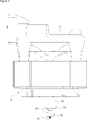
- Figure 1 - is the cross-sectional view of the compressor of the present invention.
- Figure 2 - is the sideways view of the cylinder block, the main motor, the oil suction apparatus, the first magnet and the ball bearing.
- Figure 3 - is the exploded perspective view of the cylinder block, the casing, the crankshaft, the oil suction apparatus, the auxiliary motor and the first and the second magnets.
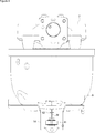
- Figure 4 - is the front view of the cylinder block, the casing, the fixing member, the auxiliary motor and the second magnet.
- the hermetic type compressor (1) comprises a main motor (2) composed of a stator (3) and a rotor (4); a crankshaft (5) that transfers the movement received from the rotor (4); a piston-rod mechanism (6); a cylinder block (7) that bears the crankshaft (5) and the piston-rod mechanism (6); a casing (8) wherein the oil for lubrication of the movable components like the main motor (2), the crankshaft (5), the piston-rod mechanism (6) and the bearings (Y) is placed; a vertical channel (9) that opens from the lower end of the crankshaft (5) that is immersed into the oil in the casing (8) into the crankshaft (5) in the axial direction, and a cylindrical oil suction apparatus (10), the outer periphery of which is in helically geared structure, that is positioned in the channel (9) one inside the other and concentrically with respect to the crankshaft (5), and that extends from the lower end of the crankshaft (5) into the channel (9)
- the compressor (1) of the present invention comprises
- auxiliary motor (11) that has an auxiliary motor shaft (M), that is connected to casing and that enables the oil suction apparatus (10) to be rotated independently from the crankshaft (5) and in the reverse direction of the crankshaft (4),
- the compressor (1) comprises a bracket (14) that enables the auxiliary motor (11) to be fixed under the casing (8), on the same axis (at the same level) with the crankshaft (5) and the oil suction apparatus (10).
- the auxiliary motor (11) can be accessed and serviced only by removing the bracket (14) without interfering with the compressor (1).
- the compressor (1) comprises an extension (15) that extends from the lower end of the oil suction apparatus (10) towards the base of the casing (8) and a ball bearing (16) wherein the extension (15) is mounted, and that enables the oil suction apparatus (10) to be pivotally housed on the casing (8) and in the channel (9) of the crankshaft (5).
- the compressor (1) furthermore comprises at least one spring (17) that is attached between the ball bearing (16) and the casing (8), that enables the ball bearing (16) to be connected to the casing (8) in a flexible manner and that attenuates the vibrations acting on the ball bearing (16).
- the spring (17) is disposed between the ball bearing (16) and the casing (8), fitted on the oppositely located protrusions and/or recesses (not shown in the figures) below the ball bearing (16) and on the upper surface of the base of the casing (8).
- the spring (17) minimizes the effect of the compressor (1) vibrations on the ball bearing (16) and hence on the oil suction apparatus (10).
- the amount oil supplied for lubrication of the movable components and the bearings (Y) is increased at low speeds of the main motor (2).
- the auxiliary motor (11) is deactivated and the power delivered to the compressor (1) can be decreased since compressor lubrication process reaches a sufficient level. Since sufficient lubrication can be performed at the initial start-up moment by operating the auxiliary motor (11) before the main motor (2) starts to operate, the time required for sucking the oil from the lower casing (8) and delivering to the bearings (Y) decreases and a sufficient amount of oil can be delivered to the bearings (Y) during this time.
- the auxiliary motor (11) rotates the oil suction apparatus (10) without any mechanical connection therebetween, only by means of the first magnet (12) and the second magnet (13).
- the main motor (2) of the compressor (1) changes to start-up position from the stop position and at low cooling requirement in the cooling device, the risk of operating without oil or insufficient lubrication is minimized.
Landscapes
- Engineering & Computer Science (AREA)
- Mechanical Engineering (AREA)
- General Engineering & Computer Science (AREA)
- Compressor (AREA)
Abstract
The present invention relates to a hermetic type compressor (1) comprising a main motor (2) composed of a stator (3) and a rotor (4); a crankshaft (5) that transfers the movement received from the rotor (4); a piston-rod mechanism (6); a cylinder block (7) that bears the crankshaft (5) and the piston-rod mechanism (6); a casing (8) wherein the oil for lubrication of the movable components and the bearings (Y) is placed; a vertical channel (9) that opens into the crankshaft (5), and a oil suction apparatus (10) that is positioned in the channel (9).
Description
The present invention relates to a compressor, the lubrication of which is improved by means of an oil suction apparatus that is actuated by an auxiliary motor, independently from the crankshaft.
In household appliances, preferably in cooling devices, the circulation of the refrigerant fluid used for the refrigeration cycle is provided by a compressor. In hermetic compressors used in cooling devices, the delivery of the lubricating oil to the bearings formed by the movable surfaces is provided by means of an oil suction apparatus. At the stopping time of the compressor, the oil in the crankshaft and the bearings trickles towards the lower casing with the effect of gravity. When the compressor operates again, this situation results in mechanical losses and dry friction in the bearings until the oil suction apparatus sucks the oil in the lower casing again and delivers to the bearings. Furthermore, since sufficient oil cannot be sucked by the oil suction apparatus at low compressor speeds, the required lubrication cannot be provided in the movable components of the compressor and the bearings. This situation adversely affects the efficiency of the compressor, resulting in abrasion and the reduction in expected product life span in movable components and the bearings due to the generated friction
In the state of the art United States Patent Application No. US2002170779, an oil suction apparatus is disclosed, that is rotated in the reverse direction of the crankshaft by means of the gears. In this embodiment known in the technique, the rotational speed of the oil suction apparatus cannot be controlled independently from the rotational speed of the crankshaft.
The aim of the present invention is the realization of a compressor, wherein lubrication of the movable components and the bearings is improved.
The compressor realized in order to attain the aim of the present invention, explicated in the first claim and the respective claims thereof, comprises a crankshaft that transfers the movement received from the main motor, a cylindrical oil suction apparatus that can rotate around its axis, that is placed inside through the end of the crankshaft immersed into the oil in the casing, the side surface of which is in helical geared shape. The compressor furthermore comprises an auxiliary motor that enables the crankshaft to be rotated in the reverse direction and that is connected to the base of the casing, a first magnet that is connected to the auxiliary motor shaft and a second magnet that is connected to the oil suction apparatus and that enables the oil suction apparatus to be rotated without any mechanical connection with the auxiliary motor, only by the magnetic force exerted by the first magnet.
The auxiliary motor is fixed under the casing by means of a bracket, at the same level with the crankshaft and the oil suction apparatus.
An extension extends from the lower end of the oil suction apparatus towards the base of the casing and the oil suction apparatus is housed so as to rotate around its axis by means of the extension attached to a ball bearing seated over the springs on the base of the casing.
By means of the present invention, the amount of oil supplied for the lubrication of the movable components is increased at low main motor speeds before the main motor start-up. When the speed of the main motor increases, the auxiliary motor can be deactivated and the power delivered to the compressor can be decreased since compressor lubrication process reaches a sufficient level. The auxiliary motor rotates the oil suction apparatus without any mechanical connection therebetween, only by means of the magnets. Since sufficient lubrication can be performed at the initial start-up moment by operating the auxiliary motor before the compressor operates, the time required for sucking the oil from the lower casing and delivering the same to the bearings decreases and a sufficient amount of oil can be delivered to the bearings during this time.
The model embodiments relating to the compressor realized in order to attain the aim of the present invention are illustrated in the attached figures, where:
Figure 1 - is the cross-sectional view of the compressor of the present invention.
Figure 2 - is the sideways view of the cylinder block, the main motor, the oil suction apparatus, the first magnet and the ball bearing.
Figure 3 - is the exploded perspective view of the cylinder block, the casing, the crankshaft, the oil suction apparatus, the auxiliary motor and the first and the second magnets.
Figure 4 - is the front view of the cylinder block, the casing, the fixing member, the auxiliary motor and the second magnet.
The elements illustrated in the figures are numbered as follows:
- Compressor
- Main motor
- Stator
- Rotor
- Crankshaft
- Piston - rod mechanism
- Cylinder block
- Casing
- Channel
- Oil suction apparatus
- Auxiliary motor
- First magnet
- Second magnet
- Bracket
- Extension
- Ball bearing
- Spring
Y: Bearing
M: Auxiliary motor shaft
The hermetic type compressor (1) comprises a main motor (2) composed of a stator (3) and a rotor (4); a crankshaft (5) that transfers the movement received from the rotor (4); a piston-rod mechanism (6); a cylinder block (7) that bears the crankshaft (5) and the piston-rod mechanism (6); a casing (8) wherein the oil for lubrication of the movable components like the main motor (2), the crankshaft (5), the piston-rod mechanism (6) and the bearings (Y) is placed; a vertical channel (9) that opens from the lower end of the crankshaft (5) that is immersed into the oil in the casing (8) into the crankshaft (5) in the axial direction, and a cylindrical oil suction apparatus (10), the outer periphery of which is in helically geared structure, that is positioned in the channel (9) one inside the other and concentrically with respect to the crankshaft (5), and that extends from the lower end of the crankshaft (5) into the channel (9) .
The compressor (1) of the present invention comprises
- an auxiliary motor (11) that has an auxiliary motor shaft (M), that is connected to casing and that enables the oil suction apparatus (10) to be rotated independently from the crankshaft (5) and in the reverse direction of the crankshaft (4),
- a first magnet (12) that is mounted to the auxiliary motor (11) and that is rotated by the auxiliary motor shaft (M), and
- a second magnet (13) that is mounted to the oil suction apparatus (10) and that enables the oil suction apparatus (10) to be rotated in a synchronous manner with the auxiliary motor (11) with the magnetic effect applied by the first magnet (12) (Figure 1).
The first magnet (12), that is activated by the auxiliary motor (11) actuated before the start-up of the main motor (2) or in cases wherein the main motor (2) is operated at low speeds and the need for the lubrication of the movable components and the bearings (Y) increases during the operation of the compressor (1), rotates the second magnet (13) disposed in the same axis and within the magnetic field thereof, thus the oil suction apparatus (10) is enabled to be rotated in the reverse direction of the crankshaft (5) without any mechanical connection between the oil suction apparatus (10) and the auxiliary motor (11).
In an embodiment of the present invention, the compressor (1) comprises a bracket (14) that enables the auxiliary motor (11) to be fixed under the casing (8), on the same axis (at the same level) with the crankshaft (5) and the oil suction apparatus (10). Thus, in case the auxiliary motor (11) malfunctions, the auxiliary motor (11) can be accessed and serviced only by removing the bracket (14) without interfering with the compressor (1).
In an embodiment of the present invention, the compressor (1) comprises an extension (15) that extends from the lower end of the oil suction apparatus (10) towards the base of the casing (8) and a ball bearing (16) wherein the extension (15) is mounted, and that enables the oil suction apparatus (10) to be pivotally housed on the casing (8) and in the channel (9) of the crankshaft (5).
The compressor (1) furthermore comprises at least one spring (17) that is attached between the ball bearing (16) and the casing (8), that enables the ball bearing (16) to be connected to the casing (8) in a flexible manner and that attenuates the vibrations acting on the ball bearing (16). The spring (17) is disposed between the ball bearing (16) and the casing (8), fitted on the oppositely located protrusions and/or recesses (not shown in the figures) below the ball bearing (16) and on the upper surface of the base of the casing (8). The spring (17) minimizes the effect of the compressor (1) vibrations on the ball bearing (16) and hence on the oil suction apparatus (10).
By means of the present invention, especially in inverter compressors (1) that can operate at variable speeds, the amount oil supplied for lubrication of the movable components and the bearings (Y) is increased at low speeds of the main motor (2). When the speed of the main motor (2) increases, the auxiliary motor (11) is deactivated and the power delivered to the compressor (1) can be decreased since compressor lubrication process reaches a sufficient level. Since sufficient lubrication can be performed at the initial start-up moment by operating the auxiliary motor (11) before the main motor (2) starts to operate, the time required for sucking the oil from the lower casing (8) and delivering to the bearings (Y) decreases and a sufficient amount of oil can be delivered to the bearings (Y) during this time. The auxiliary motor (11) rotates the oil suction apparatus (10) without any mechanical connection therebetween, only by means of the first magnet (12) and the second magnet (13). In the situation the main motor (2) of the compressor (1) changes to start-up position from the stop position and at low cooling requirement in the cooling device, the risk of operating without oil or insufficient lubrication is minimized.
Claims (4)
- A compressor (1) comprising a main motor (2) composed of a stator (3) and a rotor (4); a crankshaft (5) that transfers the movement received from the rotor (4); a piston-rod mechanism (6); a cylinder block (7) that bears the crankshaft (5) and the piston-rod mechanism (6); a casing (8) wherein the oil for lubrication of the movable components and the bearings (Y) is placed; a vertical channel (9) that opens into the crankshaft (5) in the axial direction, and a cylindrical oil suction apparatus (10), the outer periphery of which is in helically geared structure, that is positioned in the channel (9) one inside the other and concentrically with respect to the crankshaft (5), characterized in that- an auxiliary motor (11) that has an auxiliary motor shaft (M), that is connected to casing and that enables the oil suction apparatus (10) to be rotated independently from the crankshaft (5) and in the reverse direction of the crankshaft (4),- a first magnet (12) that is mounted to the auxiliary motor (11) and that is rotated by the auxiliary motor shaft (M), and- a second magnet (13) that is mounted to the oil suction apparatus (10) and that enables the oil suction apparatus (10) to be rotated in a synchronous manner with the auxiliary motor (11) with the magnetic effect applied by the first magnet (12).
- A compressor (1) as in Claim 1, characterized in that a bracket (14) that enables the auxiliary motor (11) to be fixed under the casing (8), at the same level with the crankshaft (5) and the oil suction apparatus (10).
- A compressor (1) as in Claim 1 or 2, characterized in that an extension (15) that extends from the lower end of the oil suction apparatus (10) towards the base of the casing (8) and a ball bearing (16) wherein the extension (15) is mounted, and that enables the oil suction apparatus (10) to be pivotally housed on the casing (8) and in the channel (9) of the crankshaft (5).
- A compressor (1) as in Claim 3, characterized in that at least one spring (17) that is mounted between the ball bearing (16) and the casing (8).
Applications Claiming Priority (2)
| Application Number | Priority Date | Filing Date | Title |
|---|---|---|---|
| TR201506748 | 2015-06-02 | ||
| TRA2015/06748 | 2015-06-02 |
Publications (1)
| Publication Number | Publication Date |
|---|---|
| WO2016192976A1 true WO2016192976A1 (en) | 2016-12-08 |
Family
ID=56068869
Family Applications (1)
| Application Number | Title | Priority Date | Filing Date |
|---|---|---|---|
| PCT/EP2016/060990 Ceased WO2016192976A1 (en) | 2015-06-02 | 2016-05-17 | Compressor with a movable oil suction apparatus |
Country Status (1)
| Country | Link |
|---|---|
| WO (1) | WO2016192976A1 (en) |
Cited By (2)
| Publication number | Priority date | Publication date | Assignee | Title |
|---|---|---|---|---|
| EP3770430A1 (en) * | 2019-07-26 | 2021-01-27 | Arçelik Anonim Sirketi | A compressor with improved lubrication performance |
| EP4170166A1 (en) * | 2021-10-25 | 2023-04-26 | Secop GmbH | Compressor shell for a refrigerant compressor |
Citations (3)
| Publication number | Priority date | Publication date | Assignee | Title |
|---|---|---|---|---|
| WO2005047699A1 (en) * | 2003-11-12 | 2005-05-26 | Matsushita Electric Industrial Co., Ltd. | Compressor |
| WO2009132976A1 (en) * | 2008-05-02 | 2009-11-05 | Arcelik Anonim Sirketi | A compressor |
| EP2473738A1 (en) * | 2009-08-31 | 2012-07-11 | Arçelik Anonim Sirketi | Variable capacity hermetic compressor |
-
2016
- 2016-05-17 WO PCT/EP2016/060990 patent/WO2016192976A1/en not_active Ceased
Patent Citations (3)
| Publication number | Priority date | Publication date | Assignee | Title |
|---|---|---|---|---|
| WO2005047699A1 (en) * | 2003-11-12 | 2005-05-26 | Matsushita Electric Industrial Co., Ltd. | Compressor |
| WO2009132976A1 (en) * | 2008-05-02 | 2009-11-05 | Arcelik Anonim Sirketi | A compressor |
| EP2473738A1 (en) * | 2009-08-31 | 2012-07-11 | Arçelik Anonim Sirketi | Variable capacity hermetic compressor |
Cited By (2)
| Publication number | Priority date | Publication date | Assignee | Title |
|---|---|---|---|---|
| EP3770430A1 (en) * | 2019-07-26 | 2021-01-27 | Arçelik Anonim Sirketi | A compressor with improved lubrication performance |
| EP4170166A1 (en) * | 2021-10-25 | 2023-04-26 | Secop GmbH | Compressor shell for a refrigerant compressor |
Similar Documents
| Publication | Publication Date | Title |
|---|---|---|
| US8978826B2 (en) | Compressor | |
| JP5716161B2 (en) | Hermetic compressor | |
| JP6289686B2 (en) | Scroll compressor | |
| EP1947335A2 (en) | Reciprocating compressor, in particular of the semi-hermetic type | |
| JP6726720B2 (en) | Methods for optimizing the service life of roller bearings in vacuum pumps | |
| WO2012062860A1 (en) | A hermetic compressor the lubrication performance of which is improved | |
| WO2012062852A1 (en) | A hermetic compressor comprising an oil sucking member | |
| WO2016192974A1 (en) | Compressor with a movable oil suction apparatus and a control method | |
| EP2638291B1 (en) | Hermetic compressor with oil sucking member | |
| KR20160127361A (en) | Oil Pumping Structure of Hermetic Compressor | |
| EP2724026B1 (en) | A hermetic compressor comprising an oil sucking member | |
| WO2015049192A1 (en) | A compressor with improved lubrication effectiveness | |
| KR20110101495A (en) | Compressor and Refrigerating Equipment | |
| WO2013097973A1 (en) | A hermetic compressor comprising an oil sucking member | |
| EP2473738B1 (en) | Variable capacity hermetic compressor | |
| EP2433005A1 (en) | Hermetic compressor having increased lubrication effectiveness | |
| EP3770430B1 (en) | A compressor with improved lubrication performance | |
| JP2015040471A (en) | Hermetic compressor and refrigerator using the same | |
| WO2009132976A1 (en) | A compressor | |
| KR101711539B1 (en) | Compressor and refrigerating machine having the same | |
| WO2013097971A1 (en) | A hermetic compressor comprising an oil sucking member | |
| WO2013098126A1 (en) | A compressor comprising an oil sucking member | |
| WO2020193030A1 (en) | A compressor with improved lubrication performance | |
| CN104405637A (en) | Vacuum scroll compressor | |
| KR20160105756A (en) | Reciprocating compressor and refrigerating machine having the same |
Legal Events
| Date | Code | Title | Description |
|---|---|---|---|
| 121 | Ep: the epo has been informed by wipo that ep was designated in this application |
Ref document number: 16724362 Country of ref document: EP Kind code of ref document: A1 |
|
| NENP | Non-entry into the national phase |
Ref country code: DE |
|
| 122 | Ep: pct application non-entry in european phase |
Ref document number: 16724362 Country of ref document: EP Kind code of ref document: A1 |