WO2016184481A1 - A vacuum cleaner - Google Patents
A vacuum cleaner Download PDFInfo
- Publication number
- WO2016184481A1 WO2016184481A1 PCT/EP2015/060766 EP2015060766W WO2016184481A1 WO 2016184481 A1 WO2016184481 A1 WO 2016184481A1 EP 2015060766 W EP2015060766 W EP 2015060766W WO 2016184481 A1 WO2016184481 A1 WO 2016184481A1
- Authority
- WO
- WIPO (PCT)
- Prior art keywords
- vacuum cleaner
- floor
- handles
- carrying means
- air inlet
- Prior art date
- Legal status (The legal status is an assumption and is not a legal conclusion. Google has not performed a legal analysis and makes no representation as to the accuracy of the status listed.)
- Ceased
Links
Images


Classifications
-
- A—HUMAN NECESSITIES
- A47—FURNITURE; DOMESTIC ARTICLES OR APPLIANCES; COFFEE MILLS; SPICE MILLS; SUCTION CLEANERS IN GENERAL
- A47L—DOMESTIC WASHING OR CLEANING; SUCTION CLEANERS IN GENERAL
- A47L5/00—Structural features of suction cleaners
- A47L5/12—Structural features of suction cleaners with power-driven air-pumps or air-compressors, e.g. driven by motor vehicle engine vacuum
- A47L5/22—Structural features of suction cleaners with power-driven air-pumps or air-compressors, e.g. driven by motor vehicle engine vacuum with rotary fans
- A47L5/36—Suction cleaners with hose between nozzle and casing; Suction cleaners for fixing on staircases; Suction cleaners for carrying on the back
- A47L5/362—Suction cleaners with hose between nozzle and casing; Suction cleaners for fixing on staircases; Suction cleaners for carrying on the back of the horizontal type, e.g. canister or sledge type
-
- A—HUMAN NECESSITIES
- A47—FURNITURE; DOMESTIC ARTICLES OR APPLIANCES; COFFEE MILLS; SPICE MILLS; SUCTION CLEANERS IN GENERAL
- A47L—DOMESTIC WASHING OR CLEANING; SUCTION CLEANERS IN GENERAL
- A47L9/00—Details or accessories of suction cleaners, e.g. mechanical means for controlling the suction or for effecting pulsating action; Storing devices specially adapted to suction cleaners or parts thereof; Carrying-vehicles specially adapted for suction cleaners
- A47L9/009—Carrying-vehicles; Arrangements of trollies or wheels; Means for avoiding mechanical obstacles
-
- A—HUMAN NECESSITIES
- A47—FURNITURE; DOMESTIC ARTICLES OR APPLIANCES; COFFEE MILLS; SPICE MILLS; SUCTION CLEANERS IN GENERAL
- A47L—DOMESTIC WASHING OR CLEANING; SUCTION CLEANERS IN GENERAL
- A47L9/00—Details or accessories of suction cleaners, e.g. mechanical means for controlling the suction or for effecting pulsating action; Storing devices specially adapted to suction cleaners or parts thereof; Carrying-vehicles specially adapted for suction cleaners
- A47L9/32—Handles
- A47L9/327—Handles for suction cleaners with hose between nozzle and casing
Definitions
- the present invention relates to a vacuum cleaner and, in particular, to a canister vacuum cleaner particularly easy, handy and safe to be used and to be carried.
- Canister vacuum cleaners having a body, mounted on wheels and accommodating a suction group and a dust collector, and having a suction head connected to the support body by a flexible suction hose, are particularly common on the market.
- the canister vacuum cleaners generally comprise a handle on the body for allowing the user to lift and to carry them.
- different models of canister vacuum cleaners aimed to have an improved movability and manoeuvrability, have been developed.
- various models of canister vacuum cleaners which comprise a support body carried only by a pair of large wheels and which can be propelled on the floor by pulling or pushing the hose.
- These known vacuum cleaners have an optimal manoeuvrability, since they can be moved by the user in various directions on the floor with a minimum effort and since they can be very easily turned about a vertical axis.
- the specific design of the body and the specific arrangement of the handle affect their movability, manoeuvrability and portability.
- a canister vacuum cleaner comprising a substantially spherical body and a pair of wheels mounted on the body and rotating about a same rotation axis.
- a flexible hose is connected to the frontal surface of the support body.
- the support body comprises on its top surface, between the two wheels, a handle.
- the object of the present invention is to provide a vacuum cleaner which is easy, handy and safe to be used, lifted and carried by a user.
- the vacuum cleaner according to the present invention comprises a body having the air inlet for air and dust, which body is substantially symmetrical with respect to a plane passing through the rotation axis of the wheels attached to it and the centre of the air inlet and further comprises carrying means having two or more handles arranged on the body on opposite sides of the plane.
- the vacuum cleaner according to the present invention can be therefore versatilely used with the body alternatively tilted substantially in opposite directions with respect to the wheels ensuring a substantially identical behaviour and ensuring the same possibility for the user to easily grasp a handle in order to lift and carry the vacuum cleaner.
- the handles are disposed on the body symmetrically with respect to the plane of symmetry of the body, thus ensuring the same handiness of the vacuum cleaner, however the body is tilted.
- the body comprises a main portion defined by a substantially cylindrical volume between the wheels and a protruding portion which projects from the main portion beyond the wheels and which is provided with the air inlet.
- the body is therefore tiltable around the rotation axis of the wheels, bringing the protruding portion of the body to project beyond the wheels toward different directions.
- the handles are arranged on the protruding portion of the body, so that they do not hinder the rotation of the body around the rotation axis of the wheels.
- the carrying means comprises a surrounding element which surrounds the air inlet and on which the handles are arranged.
- the handles arranged close to the air inlet can be more easily reached by the user whichever the position of the body is.
- the surrounding element has a circular shape.
- the body is movable with respect to the wheels between two resting positions in each of which the carrying means touches the floor and keeps the air inlet lifted from the floor.
- the carrying means comprises at least two braking portions, arranged on the body on opposite sides of the plane, at least one of which braking portions is susceptible of touching the floor when the body is in a resting position.
- the braking portions of the carrying means are made of a shock absorbing material.
- the shock absorbing material is a polymeric rubber or foam.
- the braking portions of the carrying means are part of the handles.
- each of the handles comprising the braking portion made of a shock absorbing material, comprises a core made of a rigid material.
- the protruding portion of the body comprises a first surface and a second surface which are opposite to each other with respect to the symmetry plane of the body and which are susceptible of alternatively face the floor when the plane is disposed parallel to the floor defining with the floor an angle ⁇ comprised between 20° and 30°.
- the carrying means comprises at least two cavities formed on the body each of which defines with a respective handle a recess for receiving the fingers of a hand of a user that grasps the handle.
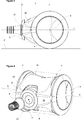
- Figure 1 and 1a are respectively a first frontal perspective view of a vacuum cleaner according to the present invention and an enlarged detail view of a particular of the vacuum cleaner.
- Figure 2 is a lateral view of the vacuum cleaner illustrated in Figure 1, wherein some parts of the vacuum cleaner have been removed and with illustrated in dotted lines the body of the vacuum cleaner rotated in different positions with respect to the wheels.
- Figure 3 is a lateral view of the vacuum cleaner illustrated in Figure 1, wherein some parts of the vacuum cleaner have been removed.
- Figure 4 is a second frontal perspective view of the vacuum cleaner illustrated in Figure 1 with a detail related to a connection element of the hose to the support body exploded.
- Figure 5 is a lateral view of the vacuum cleaner according to the present invention wherein some parts of the vacuum cleaner have been removed in order to show the internal components of the vacuum cleaner.
- the vacuum cleaner 1 according to the present invention comprises a body 2 having an air inlet 3, and two wheels 4 rotatably attached to the body 2 about a same rotation axis X for moving the vacuum cleaner 1 on the floor F.
- the vacuum cleaner 1 further comprises a suction hose 5 connected to the air inlet 3 for bringing air and dust into the body 2.
- the vacuum cleaner 1 comprises a connection element 6 for the hose 5, which is detachably connected to the body 2 at the air inlet 3, as illustrated in Figure 4.
- the vacuum cleaner 1 further comprises carrying means 7 which is arranged on the body 2 and which allows a user to lift the body 2 in order to easily carry the vacuum cleaner 1.
- the body 2 is substantially symmetrical with respect to a plane ⁇ passing through the rotation axis X of the wheels 4 and the centre O of the air inlet 3 and the carrying means 7 comprises at least two handles 8 arranged on the body 2 on opposite sides of the plane ⁇ .
- the plane ⁇ divides the body 2 into two substantially equal parts, a first part 9 and a second part 10, as apparent in Figure 3, which can alternatively face the floor F when the vacuum cleaner 1 is pulled or pushed on the floor F, as better specified hereinafter.
- the presence on the body 2 of at least two handles 8 arranged on the two opposite parts 9 and 10 of the body 2 renders the vacuum cleaner 1 particularly versatile and easy to be used, lifted or moved by a user, since in each position of the body 2 at least one of the handles 8 is easily reachable and graspable by the user.
- an embodiment of the vacuum cleaner 1 according to the invention comprising carrying means 7 having only two handles 8 is in particular illustrated, so that one handle 8 is arranged on each of the two equal parts 9 and 10 of the body 2. Differently, more than one handle 8 could be provided on each of the two equal parts of the body 2.
- Each of the handles 8, in particular, might be all-in-one with the body 2, being defined by a portion of the body suitable for being grasped by the user, or might be defined by an element or a portion of an element which is distinct from the body 2 and which is mounted on the latter.
- the air inlet 3 has preferably a circular shape, so that the centre O corresponds to the centre of the circle, as illustrated in the attached figures.
- the centre O corresponds to the geometrical centre of such shape.
- the at least two handles 8 are arranged on the body 2 symmetrically with respect to the plane ⁇ .
- This arrangement of the handles 8 on the body 2 allows substantially the same use and graspability of the vacuum cleaner 1 both when the body 2 is disposed with its first part 9 facing the floor F and when the body 2 is disposed with its second part 10 facing the floor F.
- the body 2 comprises a main portion 11 defined by a substantially cylindrical volume between the wheels 4 and a protruding portion 12 which projects from the main portion 11 beyond the wheels 4 and which is provided with the air inlet 3.
- the main portion 11 does not extend beyond the volume V ideally defined by the projection of the wheels 4 one onto the other along the rotation axis X, having preferably a concave shape, as illustrated in Figure 4.
- the body 2 comprises a main portion 11 that does not extend beyond the volume V and the fact that the body 2 has a symmetrical shape with respect to the plane ⁇ allow the vacuum cleaner 1 to be indifferently pulled or pushed on the floor F by a user on a first advancing direction A or on a second advancing direction B opposite to the first, as illustrated in Figure 2, by simply changing the relative position of the body 2 with respect to the wheels 4, rotating it around the rotation axis X of the wheels 4, and thus exchanging the part 9 or 10 of the body 2 facing the floor F.
- the handles 8 are disposed on the protruding portion 12 of the body 2.
- the handles 8 such arranged on the body 2 do not hinder the rotation of the main portion 11 of the body 2 around the rotation axis X of the wheels 4.
- the protruding portion 12 of the body 2 comprises a first surface 14 pertaining to the first part 9 of the body 2 and a second surface 15, opposite to the first surface 14 with respect to a plane ⁇ , as illustrated in Figure 5, which pertains to the second part 10 of the body 2.
- the protruding portion 12 of the body 2 further comprises a frontal surface 16, preferably convex, which joins the first surface 14 and the second surface 15 and wherein the air inlet 3 is arranged. At least one of the handles 8 is arranged on the first surface 14 of the protruding portion 12 and at least one of the handles 8 is provided on the second surface 15.
- the handle provided on the surface of the protruding portion 12 upwards facing can be easily grasped by a user to lift and to carry the body 2. Therefore, whichever position the body 2 is in, at least one handle 8 is easily accessible to the user and can be grasped by the user to lift the body 2.
- first surface 14 and the second surface 15 of the protruding portion 12 of the body 2 are susceptible of defining with the floor F an angle ⁇ comprised between 20° and 30°, as illustrated in Figure 3, when respectively facing the floor F with the plane ⁇ disposed parallel to the floor F.
- the angle ⁇ comprised between the above mentioned values ensures a sufficient space under the protruding portion 12 of the body 2 for allowing the body 2 to overgo and eventually pass over obstacles that the vacuum cleaner 1 might encounter along its path, thus improving its movability, and at the same time it ensures appropriate dimensions of the protruding portion 12.
- the carrying means 7 comprises a surrounding element 13, which surrounds the air inlet 3 and on which the handles 8 are arranged.
- the surrounding element 13 is a whole element comprising a handle 8 on the first part 9 of the body 2 and a further handle 8 on the second part 10 of the body 2.
- the surrounding element 13 where the handles 8 are arranged is provided on the body 2 around the air inlet 3 allows a user to easily and safely lift and carry the body 2 and hence the vacuum cleaner 1.
- the handles 8 of the surrounding element 13 positioned at the connection of the hose 5 with the body 2 allow the user to carry the vacuum cleaner 1 in a safe manner.
- the portion of the hose 5 close to the air inlet 3 points upwardly hence reducing the probability that the user may step on the hose 5 or be tripped by it.
- the surrounding element 13 preferably comprises joining means 17 for the connection with dust collection means 18 provided inside the body 2, such as a dust bag or a dust bin.
- the joining means 17 connects the surrounding element 13 to an opening of the dust collection means 18 to ensure a continuity of the air flux drawn by the suction hose 5 toward the interior of the dust collection bag or bin.
- the surrounding element 13 has a circular shape. Two opposite circular arcs of the surrounding element 13 define the handles 8.
- the surrounding element 13 might have a different shape, such as for instance an elliptical shape.
- the surrounding element 13 advantageously defines a housing for the connection of the hose 5. More in detail the housing is suitable for receiving the hose connection element 6.
- the body 2 is movable with respect to the wheels 4 between two resting positions R1, R2 in each of which the carrying means 7 touches the floor F and keeps the air inlet 3 clear of the floor F. More in detail the body 2 is movable between a first resting position R1, wherein the first part 9 of the body 2 faces the floor F, and a second resting position R2, wherein the second part 10 of the body faces the floor F, as illustrated in Figure 2.
- the carrying means 7, by touching the floor F and keeping the air inlet 3 lifted from the floor F, prevent the hose 5 from being bent.
- the carrying means 7 comprises at least two braking portions 19, arranged on the body 2 on opposite sides of the plane ⁇ , at least one of which braking portions 19 is susceptible of touching the floor F when the body 2 is in a resting position R1 or R2.
- the carrying means 7 are therefore designed for getting in contact with the floor F alternatively with the braking portion 19 arranged on the first part 9 of the body 2 or with the braking portion 19 arranged on the second part 10 of the body 2, exerting a braking and damping effect, when the body 2 moves respectively to the first resting position R1 or to the second resting position R2.
- the body 2 of the vacuum cleaner 1 which is generally advancing on the floor F just with the wheels 4 contacting the floor F, spontaneously moves toward one of the resting positions R1 or R2. Due to the contact of one of the braking portions 19 with the floor F and to the braking effect exerted by it, the movement of the vacuum cleaner 1 on the floor F is stopped. Moreover, the shock of the body 2 hitting the floor F is damped, hence reducing the risk of damages to the body 2 and the noise produced.
- the braking portions 19 of the carrying means 7 are made of a shock absorbing material.
- the shock absorbing material is a polymeric rubber or foam. This material has moreover suitable friction properties for exerting a proper braking force.
- the braking portions 19 of the carrying means 7 are part of the handles 8. Therefore, the handles 8 are designed for touching the floor F with their braking portions 19 when the body 2 is in one of the resting position R1 or R2.
- the handle 8 provided on the part of the body 2 facing the floor F is in contact with the latter, while the handle 8 on the opposite part of the body 2 can be easily grasp by the user.
- the handle 8 has a convex shape and is designed to touch the floor F along all its thickness when the body 2 is in a resting position R1 or R2.
- each handle 8 might have for instance a sloping shape along its thickness, which rests parallel to the floor F when the body 2 is in a resting position R1 or R2.
- a contact line i.e. a line of contact points, between the handle 8 and the floor F ensures an optimal friction force that allows to quickly and at the same time smoothly stop the advancing of the body 2 on the floor F.
- a spot contact point would not ensure a sufficient friction force to promptly stop the movement of the body 2, while a contact surface would produce an excessive friction force.
- each of the handles 8 comprises a core made of a rigid material, such as metal or a rigid polymeric material, which provides a better structural resistance.
- the body 2 is provided with at least one cavity 20 which defines with a respective handle 8 a recess for receiving the fingers of a hand of a user that grasps a handle 8.
- the handles 8 might be provided with an ergonomic shape.
- a vacuum cleaner 1 has been provided which is particularly easy, handy and safe to be used, to be lifted and to be carried by a user. Thanks to the handles 8 arranged as above described on the body 2 of the vacuum cleaner, in fact, the user can comfortably manoeuvre the vacuum cleaner 1 on the floor F and effortlessly reach one of the handles arranged on the body 2 in order to grasp it and consequently lift and carry the vacuum cleaner 1 whenever desired.
Landscapes
- Engineering & Computer Science (AREA)
- Mechanical Engineering (AREA)
- Electric Vacuum Cleaner (AREA)
Abstract
A vacuum cleaner (1) comprising a body (2) having an air inlet (3), a suction hose (4) connected to the air inlet (3) of the body (2) for bringing air and dust into the body (2), carrying means (7) mounted on the body (2) and two wheels (9) rotatably attached to the body (2) about a same rotation axis (X).
Description
The present invention relates to a vacuum cleaner and, in particular, to a canister vacuum cleaner particularly easy, handy and safe to be used and to be carried.
Canister vacuum cleaners, having a body, mounted on wheels and accommodating a suction group and a dust collector, and having a suction head connected to the support body by a flexible suction hose, are particularly common on the market. The canister vacuum cleaners generally comprise a handle on the body for allowing the user to lift and to carry them. Throughout the years different models of canister vacuum cleaners, aimed to have an improved movability and manoeuvrability, have been developed.
In the state of art, for instance, various models of canister vacuum cleaners are known which comprise a support body carried only by a pair of large wheels and which can be propelled on the floor by pulling or pushing the hose. These known vacuum cleaners have an optimal manoeuvrability, since they can be moved by the user in various directions on the floor with a minimum effort and since they can be very easily turned about a vertical axis. However, the specific design of the body and the specific arrangement of the handle affect their movability, manoeuvrability and portability.
It is for instance known from the patent document US 2 632 524 a canister vacuum cleaner comprising a substantially spherical body and a pair of wheels mounted on the body and rotating about a same rotation axis. A flexible hose is connected to the frontal surface of the support body. The support body comprises on its top surface, between the two wheels, a handle.
The object of the present invention is to provide a vacuum cleaner which is easy, handy and safe to be used, lifted and carried by a user.
This objective has been achieved by the vacuum cleaner as defined in claim 1. Further achievements have been attained by the subject-matters respectively defined in the dependent claims.
The vacuum cleaner according to the present invention comprises a body having the air inlet for air and dust, which body is substantially symmetrical with respect to a plane passing through the rotation axis of the wheels attached to it and the centre of the air inlet and further comprises carrying means having two or more handles arranged on the body on opposite sides of the plane. The vacuum cleaner according to the present invention can be therefore versatilely used with the body alternatively tilted substantially in opposite directions with respect to the wheels ensuring a substantially identical behaviour and ensuring the same possibility for the user to easily grasp a handle in order to lift and carry the vacuum cleaner.
In an embodiment of the vacuum cleaner, the handles are disposed on the body symmetrically with respect to the plane of symmetry of the body, thus ensuring the same handiness of the vacuum cleaner, however the body is tilted.
In a further embodiment, the body comprises a main portion defined by a substantially cylindrical volume between the wheels and a protruding portion which projects from the main portion beyond the wheels and which is provided with the air inlet. The body is therefore tiltable around the rotation axis of the wheels, bringing the protruding portion of the body to project beyond the wheels toward different directions.
According to an embodiment, the handles are arranged on the protruding portion of the body, so that they do not hinder the rotation of the body around the rotation axis of the wheels.
In a further embodiment, the carrying means comprises a surrounding element which surrounds the air inlet and on which the handles are arranged. The handles arranged close to the air inlet can be more easily reached by the user whichever the position of the body is.
According to a further embodiment, the surrounding element has a circular shape.
In an embodiment of the vacuum cleaner, the body is movable with respect to the wheels between two resting positions in each of which the carrying means touches the floor and keeps the air inlet lifted from the floor.
In another embodiment, the carrying means comprises at least two braking portions, arranged on the body on opposite sides of the plane, at least one of which braking portions is susceptible of touching the floor when the body is in a resting position.
In another embodiment, the braking portions of the carrying means are made of a shock absorbing material.
In a further embodiment, the shock absorbing material is a polymeric rubber or foam.
In another embodiment, the braking portions of the carrying means are part of the handles.
In another embodiment, each of the handles, comprising the braking portion made of a shock absorbing material, comprises a core made of a rigid material.
In a further embodiment, the protruding portion of the body comprises a first surface and a second surface which are opposite to each other with respect to the symmetry plane of the body and which are susceptible of alternatively face the floor when the plane is disposed parallel to the floor defining with the floor an angle α comprised between 20° and 30°.
In another embodiment, the carrying means comprises at least two cavities formed on the body each of which defines with a respective handle a recess for receiving the fingers of a hand of a user that grasps the handle.
Additional advantages of the vacuum cleaner of the present invention will become more apparent with the detailed description of the embodiments with reference to the accompanying drawings in which:
Figure 1 and 1a are respectively a first frontal perspective view of a vacuum cleaner according to the present invention and an enlarged detail view of a particular of the vacuum cleaner.
Figure 2 is a lateral view of the vacuum cleaner illustrated in Figure 1, wherein some parts of the vacuum cleaner have been removed and with illustrated in dotted lines the body of the vacuum cleaner rotated in different positions with respect to the wheels.
Figure 3 is a lateral view of the vacuum cleaner illustrated in Figure 1, wherein some parts of the vacuum cleaner have been removed.
Figure 4 is a second frontal perspective view of the vacuum cleaner illustrated in Figure 1 with a detail related to a connection element of the hose to the support body exploded.
Figure 5 is a lateral view of the vacuum cleaner according to the present invention wherein some parts of the vacuum cleaner have been removed in order to show the internal components of the vacuum cleaner.
The reference numerals of the components shown in the drawings:
- Vacuum cleaner
- Body
- Air inlet
- Wheels
- Suction hose
- Connection element
- Carrying means
- Handles
- First part of the body
- Second part of the body
- Main portion of the body
- Protruding portion of the body
- Surrounding element
- First surface
- Second surface
- Frontal surface
- Joining means
- Dust collection means
- Braking portions
- Cavity
α. Angle of the body with the floor
A. First advancing direction
B. Second advancing direction
F. Floor
L. Distance between air inlet and rotation axis
O. Centre of air inlet
π. Plane
R1. First resting position
R2. Second resting position
V. Volume
X. Rotation axis
The vacuum cleaner 1 according to the present invention comprises a body 2 having an air inlet 3, and two wheels 4 rotatably attached to the body 2 about a same rotation axis X for moving the vacuum cleaner 1 on the floor F.
The vacuum cleaner 1 further comprises a suction hose 5 connected to the air inlet 3 for bringing air and dust into the body 2.
Advantageously the vacuum cleaner 1 comprises a connection element 6 for the hose 5, which is detachably connected to the body 2 at the air inlet 3, as illustrated in Figure 4.
The vacuum cleaner 1 further comprises carrying means 7 which is arranged on the body 2 and which allows a user to lift the body 2 in order to easily carry the vacuum cleaner 1.
According to the present invention, the body 2 is substantially symmetrical with respect to a plane π passing through the rotation axis X of the wheels 4 and the centre O of the air inlet 3 and the carrying means 7 comprises at least two handles 8 arranged on the body 2 on opposite sides of the plane π.
More in detail, the plane π divides the body 2 into two substantially equal parts, a first part 9 and a second part 10, as apparent in Figure 3, which can alternatively face the floor F when the vacuum cleaner 1 is pulled or pushed on the floor F, as better specified hereinafter.
The presence on the body 2 of at least two handles 8 arranged on the two opposite parts 9 and 10 of the body 2 renders the vacuum cleaner 1 particularly versatile and easy to be used, lifted or moved by a user, since in each position of the body 2 at least one of the handles 8 is easily reachable and graspable by the user.
In the attached drawings an embodiment of the vacuum cleaner 1 according to the invention comprising carrying means 7 having only two handles 8 is in particular illustrated, so that one handle 8 is arranged on each of the two equal parts 9 and 10 of the body 2. Differently, more than one handle 8 could be provided on each of the two equal parts of the body 2.
Each of the handles 8, in particular, might be all-in-one with the body 2, being defined by a portion of the body suitable for being grasped by the user, or might be defined by an element or a portion of an element which is distinct from the body 2 and which is mounted on the latter.
The air inlet 3 has preferably a circular shape, so that the centre O corresponds to the centre of the circle, as illustrated in the attached figures. In case the air inlet 3 has a different geometrical shape, such as oval, square or rectangular, the centre O corresponds to the geometrical centre of such shape.
In an embodiment of the vacuum cleaner, the at least two handles 8 are arranged on the body 2 symmetrically with respect to the plane π.
This arrangement of the handles 8 on the body 2 allows substantially the same use and graspability of the vacuum cleaner 1 both when the body 2 is disposed with its first part 9 facing the floor F and when the body 2 is disposed with its second part 10 facing the floor F.
According to an embodiment of the vacuum cleaner 1, the body 2 comprises a main portion 11 defined by a substantially cylindrical volume between the wheels 4 and a protruding portion 12 which projects from the main portion 11 beyond the wheels 4 and which is provided with the air inlet 3. In particular, the main portion 11 does not extend beyond the volume V ideally defined by the projection of the wheels 4 one onto the other along the rotation axis X, having preferably a concave shape, as illustrated in Figure 4.
The fact that the body 2 comprises a main portion 11 that does not extend beyond the volume V and the fact that the body 2 has a symmetrical shape with respect to the plane π allow the vacuum cleaner 1 to be indifferently pulled or pushed on the floor F by a user on a first advancing direction A or on a second advancing direction B opposite to the first, as illustrated in Figure 2, by simply changing the relative position of the body 2 with respect to the wheels 4, rotating it around the rotation axis X of the wheels 4, and thus exchanging the part 9 or 10 of the body 2 facing the floor F.
In a further embodiment of the vacuum cleaner 1, the handles 8 are disposed on the protruding portion 12 of the body 2. The handles 8 such arranged on the body 2 do not hinder the rotation of the main portion 11 of the body 2 around the rotation axis X of the wheels 4.
More in detail the protruding portion 12 of the body 2 comprises a first surface 14 pertaining to the first part 9 of the body 2 and a second surface 15, opposite to the first surface 14 with respect to a plane π, as illustrated in Figure 5, which pertains to the second part 10 of the body 2.
The protruding portion 12 of the body 2 further comprises a frontal surface 16, preferably convex, which joins the first surface 14 and the second surface 15 and wherein the air inlet 3 is arranged. At least one of the handles 8 is arranged on the first surface 14 of the protruding portion 12 and at least one of the handles 8 is provided on the second surface 15.
When the vacuum cleaner 1 is pulled or pushed on the floor F or it is resting on the floor F, with the first surface 14 or the second surface 15 facing the floor F, the handle provided on the surface of the protruding portion 12 upwards facing can be easily grasped by a user to lift and to carry the body 2. Therefore, whichever position the body 2 is in, at least one handle 8 is easily accessible to the user and can be grasped by the user to lift the body 2.
In a further embodiment, the first surface 14 and the second surface 15 of the protruding portion 12 of the body 2 are susceptible of defining with the floor F an angle α comprised between 20° and 30°, as illustrated in Figure 3, when respectively facing the floor F with the plane π disposed parallel to the floor F.
The angle α comprised between the above mentioned values ensures a sufficient space under the protruding portion 12 of the body 2 for allowing the body 2 to overgo and eventually pass over obstacles that the vacuum cleaner 1 might encounter along its path, thus improving its movability, and at the same time it ensures appropriate dimensions of the protruding portion 12.
According to an embodiment of the vacuum cleaner 1 illustrated in the attached Figures, the carrying means 7 comprises a surrounding element 13, which surrounds the air inlet 3 and on which the handles 8 are arranged. In particular, the surrounding element 13 is a whole element comprising a handle 8 on the first part 9 of the body 2 and a further handle 8 on the second part 10 of the body 2.
The fact that the surrounding element 13 where the handles 8 are arranged is provided on the body 2 around the air inlet 3 allows a user to easily and safely lift and carry the body 2 and hence the vacuum cleaner 1.
When in fact the user wishes to lift the body 2, it is sufficient for him to pull the hose 5 and the body 2 toward himself and to grab one of the handles 8 positioned immediately at the end of the hose 5 connected to the body 2. Moreover, the handles 8 of the surrounding element 13 positioned at the connection of the hose 5 with the body 2 allow the user to carry the vacuum cleaner 1 in a safe manner. When the user grasps one of the handles 8 positioned close to the air inlet 3, in fact, the portion of the hose 5 close to the air inlet 3 points upwardly hence reducing the probability that the user may step on the hose 5 or be tripped by it.
The surrounding element 13 preferably comprises joining means 17 for the connection with dust collection means 18 provided inside the body 2, such as a dust bag or a dust bin. Advantageously, the joining means 17 connects the surrounding element 13 to an opening of the dust collection means 18 to ensure a continuity of the air flux drawn by the suction hose 5 toward the interior of the dust collection bag or bin.
According to a further embodiment of the vacuum cleaner 1 illustrated in the attached Figures, the surrounding element 13 has a circular shape. Two opposite circular arcs of the surrounding element 13 define the handles 8. The surrounding element 13 might have a different shape, such as for instance an elliptical shape.
The surrounding element 13 advantageously defines a housing for the connection of the hose 5. More in detail the housing is suitable for receiving the hose connection element 6.
According to an embodiment of the vacuum cleaner 1, the body 2 is movable with respect to the wheels 4 between two resting positions R1, R2 in each of which the carrying means 7 touches the floor F and keeps the air inlet 3 clear of the floor F. More in detail the body 2 is movable between a first resting position R1, wherein the first part 9 of the body 2 faces the floor F, and a second resting position R2, wherein the second part 10 of the body faces the floor F, as illustrated in Figure 2. The carrying means 7, by touching the floor F and keeping the air inlet 3 lifted from the floor F, prevent the hose 5 from being bent.
According to an embodiment of the vacuum cleaner 1, the carrying means 7 comprises at least two braking portions 19, arranged on the body 2 on opposite sides of the plane π, at least one of which braking portions 19 is susceptible of touching the floor F when the body 2 is in a resting position R1 or R2.
The carrying means 7 are therefore designed for getting in contact with the floor F alternatively with the braking portion 19 arranged on the first part 9 of the body 2 or with the braking portion 19 arranged on the second part 10 of the body 2, exerting a braking and damping effect, when the body 2 moves respectively to the first resting position R1 or to the second resting position R2.
The presence on the body 2 of the braking portions 19 intended to get in contact with the floor F when the body 2 moves to a resting position R1 or R2, as it happens when a user stops pulling or pushing the hose 5 of the vacuum cleaner 1 while moving it on the floor F, allows to control in a precise manner the movements of the vacuum cleaner 1 on the floor F.
As far as the user stops pulling or pushing the hose 5, in fact, the body 2 of the vacuum cleaner 1, which is generally advancing on the floor F just with the wheels 4 contacting the floor F, spontaneously moves toward one of the resting positions R1 or R2. Due to the contact of one of the braking portions 19 with the floor F and to the braking effect exerted by it, the movement of the vacuum cleaner 1 on the floor F is stopped. Moreover, the shock of the body 2 hitting the floor F is damped, hence reducing the risk of damages to the body 2 and the noise produced.
To this aim, in an embodiment of the vacuum cleaner 1, the braking portions 19 of the carrying means 7 are made of a shock absorbing material. In a further embodiment, the shock absorbing material is a polymeric rubber or foam. This material has moreover suitable friction properties for exerting a proper braking force.
According to an embodiment, the braking portions 19 of the carrying means 7 are part of the handles 8. Therefore, the handles 8 are designed for touching the floor F with their braking portions 19 when the body 2 is in one of the resting position R1 or R2.
Hence, according to this last embodiment, when the body 2 is in one of the resting positions R1 or R2, the handle 8 provided on the part of the body 2 facing the floor F is in contact with the latter, while the handle 8 on the opposite part of the body 2 can be easily grasp by the user.
In a further embodiment, the handle 8 has a convex shape and is designed to touch the floor F along all its thickness when the body 2 is in a resting position R1 or R2. As illustrated in Figure 2, each handle 8 might have for instance a sloping shape along its thickness, which rests parallel to the floor F when the body 2 is in a resting position R1 or R2. It has in fact been verified that a contact line, i.e. a line of contact points, between the handle 8 and the floor F ensures an optimal friction force that allows to quickly and at the same time smoothly stop the advancing of the body 2 on the floor F. A spot contact point would not ensure a sufficient friction force to promptly stop the movement of the body 2, while a contact surface would produce an excessive friction force.
In a further embodiment, each of the handles 8 comprises a core made of a rigid material, such as metal or a rigid polymeric material, which provides a better structural resistance.
According to an embodiment of the vacuum cleaner 1, the body 2 is provided with at least one cavity 20 which defines with a respective handle 8 a recess for receiving the fingers of a hand of a user that grasps a handle 8.
In order to render the grip more secure and comfortable for the user, the handles 8 might be provided with an ergonomic shape.
With the present invention, a vacuum cleaner 1 has been provided which is particularly easy, handy and safe to be used, to be lifted and to be carried by a user. Thanks to the handles 8 arranged as above described on the body 2 of the vacuum cleaner, in fact, the user can comfortably manoeuvre the vacuum cleaner 1 on the floor F and effortlessly reach one of the handles arranged on the body 2 in order to grasp it and consequently lift and carry the vacuum cleaner 1 whenever desired.
Claims (14)
- A vacuum cleaner (1) comprising:- a body (2) having an air inlet (3);- a suction hose (5) connected to the air inlet (3) for bringing air and dust into the body (2);- two wheels (4) rotatably attached to the body (2) about a same rotation axis (X); and- carrying means (7) arranged on the body (2);characterized in that the body (2) is substantially symmetrical with respect to a plane (π) passing through the rotation axis (X) of the wheels (4) and the centre (O) of the air inlet (3) and the carrying means (7) comprises at least two handles (8) arranged on the body (2) on opposite sides of the plane (π).
- A vacuum cleaner (1) as claimed in Claim 1, characterized in that said at least two handles (8) are arranged on the body (2) symmetrically with respect to the plane (π).
- A vacuum cleaner (1) as claimed in Claim 1 or 2, characterized in that the body (2) comprises a main portion (11) defined by a substantially cylindrical volume between the wheels (4) and a protruding portion (12) which projects from the main portion (11) beyond the wheels (4) and which is provided with the air inlet (3).
- A vacuum cleaner as claimed in Claim 3, characterized in that the handles (8) are arranged on the protruding portion (12) of the body (2).
- A vacuum cleaner (1) as claimed in any of the previous Claims, characterized in that the carrying means (7) comprises a surrounding element (13) which surrounds the air inlet (3) and on which the handles (8) are arranged.
- A vacuum cleaner as claimed in Claim 5, characterized in that the surrounding element (13) has a circular shape.
- A vacuum cleaner (1) as claimed in any of the previous Claims, characterized in that the body (2) is movable with respect to the wheels (4) between two resting positions (R1, R2) in each of which the carrying means (7) touches the floor (F) and keeps the air inlet (3) lifted from the floor (F).
- A vacuum cleaner (1) as claimed in Claim 7, characterized in that the carrying means (7) comprises at least two braking portions (19), arranged on the body (2) on opposite sides of the plane (π), at least one of which braking portions (19) is susceptible of touching the floor (F) when the body (2) is in a resting position (R1, R2).
- A vacuum cleaner as claimed in Claim 8, characterized in that at least the braking portions (19) of the carrying means (7) are made of a shock absorbing material.
- A vacuum cleaner as claimed in Claim 9, characterized in that said shock absorbing material is a polymeric rubber or foam.
- A vacuum cleaner as claimed in any of Claims 8 to 10, characterized in that the at least two braking portions (19) of the carrying means (7) are part of the at least two handles (8).
- A vacuum cleaner as claimed in Claim 8, characterized in that each of the handles (8) comprises a core made of a rigid material.
- A vacuum cleaner as claimed in Claim 3 or 4, characterized in that the protruding portion (12) of the body (2) comprises a first surface (14) and a second surface (15) opposite to each other with respect to the plane (π) and susceptible of alternatively face the floor (F) when the plane (π) is disposed parallel to the floor (F) defining with the floor (F) an angle α comprised between 20° and 30°.
- A vacuum cleaner as claimed in any of the previous Claims, characterized in that the carrying means (7) comprises at least two cavities (20) formed on the body (2) each of which defines with a respective handle (8) a recess for receiving the fingers of a hand of a user that grasps the handle (8).
Priority Applications (1)
| Application Number | Priority Date | Filing Date | Title |
|---|---|---|---|
| PCT/EP2015/060766 WO2016184481A1 (en) | 2015-05-15 | 2015-05-15 | A vacuum cleaner |
Applications Claiming Priority (1)
| Application Number | Priority Date | Filing Date | Title |
|---|---|---|---|
| PCT/EP2015/060766 WO2016184481A1 (en) | 2015-05-15 | 2015-05-15 | A vacuum cleaner |
Publications (1)
| Publication Number | Publication Date |
|---|---|
| WO2016184481A1 true WO2016184481A1 (en) | 2016-11-24 |
Family
ID=53175069
Family Applications (1)
| Application Number | Title | Priority Date | Filing Date |
|---|---|---|---|
| PCT/EP2015/060766 Ceased WO2016184481A1 (en) | 2015-05-15 | 2015-05-15 | A vacuum cleaner |
Country Status (1)
| Country | Link |
|---|---|
| WO (1) | WO2016184481A1 (en) |
Cited By (2)
| Publication number | Priority date | Publication date | Assignee | Title |
|---|---|---|---|---|
| CN110022746A (en) * | 2016-12-05 | 2019-07-16 | 东芝生活电器株式会社 | Electric dust collector |
| CN116829038A (en) * | 2021-02-05 | 2023-09-29 | Seb公司 | Suction assembly equipped with concave leading edge |
Citations (6)
| Publication number | Priority date | Publication date | Assignee | Title |
|---|---|---|---|---|
| AT107187B (en) * | 1926-09-01 | 1927-09-10 | Ernst Ing Meissner | Mobile vacuum cleaner. |
| US2231326A (en) * | 1937-11-05 | 1941-02-11 | Air Way Electric Appl Corp | Vacuum cleaner |
| US2769996A (en) * | 1953-12-21 | 1956-11-13 | Gen Electric | Mobile vacuum cleaner having a hose adapted to be used as a pushing or pulling means therefor |
| JP2002355198A (en) * | 2001-09-20 | 2002-12-10 | Hitachi Ltd | Electric vacuum cleaner |
| DE202010002005U1 (en) * | 2009-02-11 | 2010-05-06 | Koninklijke Philips Electronics N.V. | vacuum cleaner |
| EP2368471A1 (en) * | 2008-11-26 | 2011-09-28 | Kabushiki Kaisha Toshiba | Electric cleaner |
-
2015
- 2015-05-15 WO PCT/EP2015/060766 patent/WO2016184481A1/en not_active Ceased
Patent Citations (6)
| Publication number | Priority date | Publication date | Assignee | Title |
|---|---|---|---|---|
| AT107187B (en) * | 1926-09-01 | 1927-09-10 | Ernst Ing Meissner | Mobile vacuum cleaner. |
| US2231326A (en) * | 1937-11-05 | 1941-02-11 | Air Way Electric Appl Corp | Vacuum cleaner |
| US2769996A (en) * | 1953-12-21 | 1956-11-13 | Gen Electric | Mobile vacuum cleaner having a hose adapted to be used as a pushing or pulling means therefor |
| JP2002355198A (en) * | 2001-09-20 | 2002-12-10 | Hitachi Ltd | Electric vacuum cleaner |
| EP2368471A1 (en) * | 2008-11-26 | 2011-09-28 | Kabushiki Kaisha Toshiba | Electric cleaner |
| DE202010002005U1 (en) * | 2009-02-11 | 2010-05-06 | Koninklijke Philips Electronics N.V. | vacuum cleaner |
Cited By (3)
| Publication number | Priority date | Publication date | Assignee | Title |
|---|---|---|---|---|
| CN110022746A (en) * | 2016-12-05 | 2019-07-16 | 东芝生活电器株式会社 | Electric dust collector |
| CN110022746B (en) * | 2016-12-05 | 2021-11-19 | 东芝生活电器株式会社 | Electric vacuum cleaner |
| CN116829038A (en) * | 2021-02-05 | 2023-09-29 | Seb公司 | Suction assembly equipped with concave leading edge |
Similar Documents
| Publication | Publication Date | Title |
|---|---|---|
| EP3852592B1 (en) | Cleaning head for a surface treatment apparatus having one or more stabilizers and surface treatment apparatus having the same | |
| EP2534988B1 (en) | Upright vacuum cleaner | |
| JP6229169B2 (en) | Vacuum cleaner suction tool and vacuum cleaner provided with the same | |
| US8171600B2 (en) | Omni-directional handle | |
| US20200187739A1 (en) | Vacuum | |
| JP2015082989A (en) | Knapsack type implement | |
| WO2013121702A1 (en) | Suction device for electric vacuum cleaner, and electric vacuum cleaner with same | |
| JP2013059525A (en) | Vacuum cleaner | |
| US20230397546A1 (en) | Blower | |
| CN102227184B (en) | electric vacuum cleaner | |
| JP5390204B2 (en) | Electric vacuum cleaner | |
| JP4613774B2 (en) | Electric vacuum cleaner | |
| JP2014221130A (en) | Electric vacuum cleaner | |
| JP2010125009A (en) | Electric vacuum cleaner | |
| JP2014204773A (en) | Vacuum cleaner | |
| WO2016184482A1 (en) | A vacuum cleaner | |
| JP7452261B2 (en) | vacuum cleaner | |
| JP2016214508A (en) | Suction tool and vacuum cleaner | |
| JP5857023B2 (en) | Carry Bag | |
| JP6056377B2 (en) | Electric vacuum cleaner | |
| CN211883598U (en) | Hand-held type surface cleaning device | |
| JP3168017U (en) | Table tennis racket | |
| KR100953267B1 (en) | Vacuum cleaner | |
| JP3116155U (en) | Stroller handle height and angle adjustable removable device | |
| JP2024098884A (en) | Vacuum cleaner |
Legal Events
| Date | Code | Title | Description |
|---|---|---|---|
| 121 | Ep: the epo has been informed by wipo that ep was designated in this application |
Ref document number: 15721751 Country of ref document: EP Kind code of ref document: A1 |
|
| NENP | Non-entry into the national phase |
Ref country code: DE |
|
| 122 | Ep: pct application non-entry in european phase |
Ref document number: 15721751 Country of ref document: EP Kind code of ref document: A1 |