WO2016179642A1 - Optimized non-uniform linear antenna arrays - Google Patents
Optimized non-uniform linear antenna arrays Download PDFInfo
- Publication number
- WO2016179642A1 WO2016179642A1 PCT/AU2016/050307 AU2016050307W WO2016179642A1 WO 2016179642 A1 WO2016179642 A1 WO 2016179642A1 AU 2016050307 W AU2016050307 W AU 2016050307W WO 2016179642 A1 WO2016179642 A1 WO 2016179642A1
- Authority
- WO
- WIPO (PCT)
- Prior art keywords
- antenna
- arch
- linear antenna
- linear
- angle
- Prior art date
- Legal status (The legal status is an assumption and is not a legal conclusion. Google has not performed a legal analysis and makes no representation as to the accuracy of the status listed.)
- Ceased
Links
Classifications
-
- H—ELECTRICITY
- H01—ELECTRIC ELEMENTS
- H01Q—ANTENNAS, i.e. RADIO AERIALS
- H01Q21/00—Antenna arrays or systems
- H01Q21/06—Arrays of individually energised antenna units similarly polarised and spaced apart
- H01Q21/08—Arrays of individually energised antenna units similarly polarised and spaced apart the units being spaced along or adjacent to a rectilinear path
- H01Q21/10—Collinear arrangements of substantially straight elongated conductive units
-
- H—ELECTRICITY
- H01—ELECTRIC ELEMENTS
- H01Q—ANTENNAS, i.e. RADIO AERIALS
- H01Q21/00—Antenna arrays or systems
- H01Q21/06—Arrays of individually energised antenna units similarly polarised and spaced apart
- H01Q21/20—Arrays of individually energised antenna units similarly polarised and spaced apart the units being spaced along or adjacent to a curvilinear path
-
- H—ELECTRICITY
- H01—ELECTRIC ELEMENTS
- H01Q—ANTENNAS, i.e. RADIO AERIALS
- H01Q21/00—Antenna arrays or systems
- H01Q21/06—Arrays of individually energised antenna units similarly polarised and spaced apart
- H01Q21/22—Antenna units of the array energised non-uniformly in amplitude or phase, e.g. tapered array or binomial array
Definitions
- This disclosure relates to linear antenna arrays and methods for configuring linear antenna arrays.
- MMW millimeter wave
- the MMW frequency band presents a very wide range of spectrum, it is constituted of many frequency segments with distinct channel characteristics and various service restrictions imposed by regulators in different countries.
- the severe propagation loss also significantly reduces the richness of scattering in an MMW communication environment, which makes the number of paths in the channel generally very small.
- an MMW MFMO system is dominated mainly by the line-of- sight (LoS) transmission as the other reflected paths undergo much longer propagation path lengths and suffer more severe propagation loss than the LoS path.
- the channel is modeled as a MFMO LoS matrix with the fading coefficients between different transmit-receive antenna pairs highly correlated.
- Such an MMW MFMO LoS channel matrix is rank deficient, which significantly degrades the achievable multiplexing gain of the channel.
- a LoS MIMO channel with uniform linear antenna arrays (ULAs) at both ends may show that the channel vectors experienced by different transmit/receive antennas can be mutually orthogonal if the antenna numbers, spacings and the communication distance between the transmitter and receiver satisfy the so-called Rayleigh distance criterion, indicating that the maximum multiplexing gain is indeed achievable in pure LoS environments.
- the communication distance is larger than the farthest distance that can fulfill the Rayleigh distance criterion
- the practically achievable multiplexing gain of a ULA-based LoS MIMO channel is limited for given aperture sizes of the transmit/receive ULAs.
- a linear antenna array comprises a linear antenna base and at least four antenna groups, each antenna group comprising one or more antenna elements electrically connected to the antenna base and the at least four antenna groups being located along the linear antenna base according to a projection of multiple points of an arch onto the linear antenna base, the multiple points of the arch defining respective radii, wherein
- the linear antenna base is a chord of the arch
- the multiple points of the arch are distributed along the arch such that an angle between two adjacent radii is equal to the angle between any other two adjacent radii.
- the arch is fully defined by its angle when the linear antenna base with a given length is a chord.
- the angle can be determined by a one-dimensional search to optimise the locations of the antenna groups to the given criteria.
- the antenna groups are located along the linear antenna base according to the projection. This comprises being located at the exact position of the projection of the multiple points as well as within a vicinity of the exact position of the projection as long as the overall characteristic of the antenna is not substantially different to the case of exact positioning.
- the distance between adjacent antenna elements may vary by up to 10% or up to 1% without substantially changing the overall characteristic of the antenna.
- the coordinates ⁇ may satisfy the following condition:
- the antenna groups are located such that the centre of each antenna group is located according to the projection.
- the linear antenna array may be specified for a threshold signal to noise ratio and the arch defines an angle of the arch based on the threshold signal to noise ratio.
- the angle of the arch may be such that a dynamic range of eigenvalues of a matrix of a channel defined by the linear antenna array is minimised based on the threshold signal to noise ratio.
- Each of the at least four antenna groups may be located along the linear antenna base according to sm ⁇ - 1 - ⁇
- ⁇ ⁇ k is a one-dimensional coordinate of antenna group k from a central point of the linear antenna array and along the linear antenna array
- L is the length of the antenna base
- ⁇ ⁇ is the angle of the arch
- K is the number of antenna groups.
- Each antenna group may comprise exactly one antenna element that is located along the linear antenna base according to the projection.
- Each antenna group may comprise two or more antenna elements and the two or more antenna elements may be uniformly distributed along the antenna base within that group.
- the antenna base defines a base length and an element length which may be such that the antenna array is suitable for millimetre wave or massive antenna wireless communications.
- the linear antenna array comprises a linear antenna base and at least four antenna groups. Each antenna group comprises one or more antenna elements electrically connected to the antenna base.
- the method comprises:
- the linear antenna base is a chord of the arch
- the multiple points of the arch are distributed along the arch such that an angle between two adjacent radii is equal to the angle between any other two adjacent radii.
- Determining the locations may comprise determining an angle of the arch based on a threshold signal to noise ratio.
- Determining the angle of the arch may comprise determining the angle of the arch that optimises eigenvalues of a matrix of a channel defined by the linear antenna array for the threshold signal to noise ratio.
- Determining the angle of the arch that optimises eigenvalues may comprise determining the angle of the arch that minimises a dynamic range of the eigenvalues.
- Determining the angle of the arch that optimises the eigenvalues may comprise performing a one-dimensional search in relation to the eigenvalues.
- Determining the locations may comprise determining the locations based on a number of groups.
- Determining the locations may comprise determining the locations according to sin ⁇ - 1 - ⁇
- ⁇ ⁇ k is a one-dimensional coordinate of antenna group k from a central point of the linear antenna array and along the linear antenna array
- L is the length of the antenna base
- ⁇ ⁇ is the angle of the arch
- K is the number of antenna groups.
- the method may further comprise generating a user interface comprising a graphical representation of a simulated antenna characteristic based on the locations of antenna groups.
- a computer system for configuring a linear antenna array comprises:
- an input port to receive design parameters of the linear antenna array, and a processor to determine locations of the at least four antenna groups along the linear antenna base based on a projection of multiple points of an arch onto the linear antenna base, the multiple points of the arch defining respective radii, wherein
- the linear antenna base is a chord of the arch
- the multiple points of the arch are distributed along the arch such that an angle between two adjacent radii is equal to the angle between any other two adjacent radii.
- Fig. 1 illustrates a non-uniform linear antenna array (NULA).
- NULA non-uniform linear antenna array
- Fig. 2 illustrates a method for configuring a NULA.
- Fig. 3 illustrates a computer system for configuring a NULA.
- Fig. 4 illustrates a 3-D geometrical model for a channel with arbitrarily deployed NULAs at both link ends.
- Fig. 5 illustrates a numerical algorithm as executed by the processor of Fig. 3.
- Fig. 6 illustrates a Fekete-point distribution
- Fig. 7 illustrates detailed values of the Fekete-points of Fig. 6.
- Fig. 8 illustrates a Fekete-points approximation using a projected arch type distribution.
- Fig. 9 illustrates a table of values of angles of the arch of Fig. 8 and their approximation error.
- Fig. 10 illustrates a plot of optimized angles of the arch of Fig. 8.
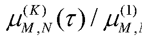
- Fig. 13 plots the curves of ⁇ ⁇ ⁇ ( ⁇ ) / ⁇ ⁇ ⁇ ( ⁇ ) versus ⁇ achieved by ULAs and optimized NULAs in various channels.
- Fig. 14 plots the values of achieved by the general groupwise PAT distributed NULA deployment with various angles ⁇ . Description of Embodiments
- Fig. 1 illustrates a non-uniform linear antenna array (NULA) 100.
- NULA 100 comprises eight antenna elements, such as antenna element 102, electrically connected to a linear antenna base 103.
- the antenna base extends orthogonally to the length of the antenna elements.
- This disclosure relates to the NULA 100 deployment optimization problem for MMW LoS MFMO systems.
- One example target may be to maximize the effective multiplexing gain (EMG) of the channel in the general system configurations, where the EMG is defined as the number of large channel eigenmodes that are actually utilized at a given finite signal-to-noise ratio (SNR).
- EMG effective multiplexing gain
- NULA 100 comprises multiple antenna groups but for clarity of presentation of Fig. 1, each group comprises only a single antenna element 102. As a result, NULA 100 comprises eight antenna elements in eight groups.
- NULA 100 is printed on a circuit board 104 and comprises an antenna feed pad 105, which allows convenient integration with other electronics components in a small device, such as a mobile phone or mobile Wifi hotspot.
- NULA 100 defines a central point 106, which lies anywhere on a symmetry axis 108 of NULA 100. Each antenna element 102 also defines a symmetry axis 110 of that antenna element 102. The location of antenna element 102 is defined as the one- dimensional coordinate along the antenna base 103 of symmetry axis 110 from symmetry axis 108, that is, the one-dimensional coordinate is negative for antenna elements on the left half of NULA 100 and positive for antenna elements on the right half of NULA 100. NULA 100 further defines a base length 114 that is the distance between the two outermost antenna elements 116 and 118 of NULA 100. The base length may also be referred to as an array length L.
- Fig. 2 illustrates a method 200 for configuring NULA 100 as performed by a processor of a computer system.
- the method 200 commences by receiving 202 design parameters, such as wavelength and array length.
- the processor determines locations of the antenna elements along the linear antenna base 103 according to a projection of multiple points of an arch 120 onto the linear antenna base 103.
- Each point of the arch 120 such as example point 122, defines a radius, such as example radius 124.
- other points on the arch 120 define radii 126, 128 and 130.
- the linear antenna base 103 is the chord of the arch 120 and the multiple points of the arch are distributed along the arch such that an angle between two adjacent radii is equal to the angle between any other two adjacent radii. In the example of Fig. 1, the angle between adjacent radii 124 and 126 is equal to the angle between radii 126 and 128 and to the angle between 128 and 130.
- Fig. 3 illustrates a computer system 300 for configuring NULA 100.
- the computer system 300 comprises a processor 302 connected to a program memory 304, a data memory 306, a communication port 308 and a user port 310.
- the program memory 304 is a non-transitory computer readable medium, such as a hard drive, a solid state disk or CD-ROM.
- Software that is, an executable program stored on program memory 304 causes the processor 302 to perform the method in Fig. 2, that is, processor 302 receives design parameters and determines locations of the antenna elements along the linear antenna base based on a projection of multiple points of an arch onto the linear antenna base.
- the term "determining a location” refers to calculating a value that is indicative of the location. This also applies to related terms.
- the processor 302 may then store the locations on data memory 306, such as on RAM or a processor register. Processor 302 may also send the determined locations via communication port 308 to an antenna fabrication device or to an antenna layout software module. [40] The processor 302 may receive data, such as antenna design parameters, from data memory 306 as well as from the communications port 308 and the user port 310, which is connected to a display 312 that shows a visual representation 314 of the antenna or antenna characteristics to an antenna designer 316. In one example, the processor 302 receives design parameters data via communications port 308, such as by using a Wi-Fi network according to IEEE 802.11. The Wi-Fi network may be a decentralised ad-hoc network, such that no dedicated management infrastructure, such as a router, is required or a centralised network with a router or access point managing the network.
- the processor 302 receives and processes the design parameters in real time. This means that the processor 302 determines the distances of antenna elements every time design parameters are received and completes this calculation before processor 302 receives next update. This allows real-time adjustments of the antenna array.
- communications port 308 and user port 310 are shown as distinct entities, it is to be understood that any kind of data port may be used to receive data, such as a network connection, a memory interface, a pin of the chip package of processor 302, or logical ports, such as IP sockets or parameters of functions stored on program memory 304 and executed by processor 302. These parameters may be stored on data memory 306 and may be handled by-value or by-reference, that is, as a pointer, in the source code.
- the processor 302 may receive data through all these interfaces, which includes memory access of volatile memory, such as cache or RAM, or non-volatile memory, such as an optical disk drive, hard disk drive, storage server or cloud storage.
- volatile memory such as cache or RAM
- non-volatile memory such as an optical disk drive, hard disk drive, storage server or cloud storage.
- the computer system 300 may further be implemented within a cloud computing environment, such as a managed group of interconnected servers hosting a dynamic number of virtual machines.
- any receiving step may be preceded by the processor 302 determining or computing the data that is later received. For example, the processor 302 determines a design parameter and stores the design parameter in data memory 306, such as RAM or a processor register. The processor 302 then requests the data from the data memory 306, such as by providing a read signal together with a memory address.
- the data memory 306 provides the data as a voltage signal on a physical bit line and the processor 302 receives the design parameter via a memory interface.
- nodes, edges, graphs, solutions, variables, matrices, vectors, points, models and the like refer to data structures, which are physically stored on data memory 306 or processed by processor 302. Further, for the sake of brevity when reference is made to particular variable names, such as "point” or “solution” this is to be understood to refer to values of variables stored as physical data in computer system 300.
- This disclosure addresses the antenna array deployment optimization problem for point-to-point millimetre wave (MMW) channels with non -uniform linear antenna arrays (NULAs) equipped at both the transmitter and receiver.
- MMW millimetre wave
- NULAs non -uniform linear antenna arrays
- LoS line-of-sight
- MTMO multiple-input multiple-output
- EMG effective multiplexing gain
- AWGN complex additive white Gaussian noise
- H ⁇ /! m (i ⁇ G C Mx " is the channel response matrix.
- processor 302 follows the ray tracing principle and models each entry of H as where h m,n beaut is the channel coefficient from the n-t transmit antenna to the m -th receive antenna, d m n is the distance between them, ⁇ is the signal wavelength, and p contains all relevant constants such as attenuation and phase rotation caused by the antenna patterns at both the transmitter and receiver.
- FIG. 4 illustrates a 3-D geometrical model 400 for a MMW LoS MIMO channel with arbitrarily deployed NULAs 402 and 404 at both link ends.
- the receive NULA 402 lies in the x- z. plane centred at the origin.
- the receive NULA 404 is centred on the positive half of z, -axis with distance D from the origin.
- the related spherical angles, 0 t 406 , 6 r 408 and ⁇ ⁇ 410, are marked in the figure. Specifically, 0 t 406 denotes the angle between the transmit NULA and x-axis, 6 r 408 is the angle between the receive NULA and x-axis, and ⁇ ⁇ 408 denotes the angle between the projected vector of the receive NULA in the y - z plane and z, -axis.
- processor 302 exploits the impact of antenna deployments, i.e., ⁇ c rm ⁇ and ⁇ a t n ⁇ , on these eigenvalues and optimizes both ⁇ cc rm ⁇ and ⁇ a t n ⁇ for a channel capacity improvement.
- the channel gain matrix G M ⁇ ( ⁇ ) in (8) can be further simplified, with its entries, denoted by ⁇ g m n ⁇ m, n e ⁇ 1 , 2, ⁇ ⁇ ⁇ , M ⁇ ⁇ , being written as
- D Ray NL r L t I ⁇ ( ⁇ - l)(N -1) is called Rayleigh distance.
- M N
- the Rayleigh distance is defined as
- EEOF effective degrees of freedom
- /( ⁇ ) is an indicator function taking a value of 1 if its argument is true and 0 otherwise
- ⁇ is a pre-determined threshold.
- ⁇ ⁇ ⁇ ( ⁇ ) physically stands for the number of large eigenmodes that are actually utilized for signal transmission, which is also the number of independent spatial streams that are indeed supported by the channel at certain finite SNRs.
- EMG effective multiplexing gain
- processor 302 may first consider the asymptotic channel characterization in the extreme case of r— » 0, based on which the antenna array optimization criterion can be extracted.
- ⁇ 7 ⁇ ⁇ ⁇ ⁇ 2 ⁇ ' ⁇ - 1) + ⁇ ( ⁇ ,2(m-l) (20) where o(x) is a higher order infinitesimal of variable
- processor 302 is to transmit K (K ⁇ M) parallel data streams over an M -by- N LoS MMW MIMO channel. Then it is easy to see that the best way is to transmit them along the largest K eigenmodes of the channel. Assuming a high transmit SNR ⁇ and equal power allocation among all K data streams, we can write the corresponding channel capacity as
- the first three terms in (23) are independent of the antenna deployment, while the fourth and fifth terms are determined by, respectively, the transmit and receive antenna deployments ⁇ c t n ⁇ and ⁇ c r m ⁇ . Therefore asymptotically, the criterion of antenna deployment optimization for maximizing the channel capacity in (23) can be designed as follows.
- processor 302 divides all the N antenna elements into K groups with approximately the same sizes.
- the antennas in the same group are compactly co-located, e.g., forming a ULA with the minimum spacing of ⁇ /2, while the centres of these K groups follow the abovementioned Fekete-point distribution.
- V 4a k i i,i ⁇ k(ock-ai)
- Fig. 5 illustrates a numerical algorithm 500 as executed by processor 302 to solve Problem P4. Note that in algorithm 500, the function g k (ak) may always be calculated using the most recently updated i.e.,
- Fig. 9 illustrates a table 900 of values of ⁇ ⁇ for PAT Approximation and their Approximation Error.
- Fig. 10 illustrates a plot 1000 of these optimized ⁇ ⁇ ⁇ .
- processor 302 analytically optimizes the NULA deployment in the extreme case of ⁇ — 0.
- processor 302 analytically optimizes the NULA deployment in the extreme case of ⁇ — 0.
- We will now numerically demonstrate the asymptotic optimality of our proposed groupwise Fekete point distributed NULA deployment.
- we will proposed a generalized groupwise PAT NULA deployment as an extension of the asymptotically optimal groupwise Fekete point distributed NULA deployment, which is more general and suitable for practical MMW LoS MIMO systems.
- Figs. 11a and l ib illustrate the values of the dynamic range of eigenvalues, which is calculated by ⁇ ⁇ ) , versus ⁇ achieved by ULAs and optimized
- Fig. 13 plots the curves of ⁇ ⁇ ⁇ ⁇ ) ⁇ ⁇ ⁇ ) versus ⁇ achieved by ULAs and optimized NULAs in various MMW LoS MTMO channels. Similar to Figs. 1 1a and l ib, processor 302 can obtain from Fig. 13 the detailed value of ⁇ ( ⁇ for any given value of the threshold ⁇ in each system. We can make the following observations from Fig. 13. [141] Given ⁇ , the value of increases with the antenna numbers M and N in the ULA-based systems, but remains unchanged in the optimized NULA-based systems. This observation is the same as that made from Fig. 5 and reflects the superiority of the groupwise NULA deployment.
- NULA-based system is always smaller than that in the corresponding ULA-based system, indicating that the proposed groupwise Fekete point distributed NULA deployment is indeed asymptotically optimal.
- processor 302 when processor 302 aims to achieve a higher EMG (e.g., > 4 ), the previously proposed groupwise Fekete point distributed NULA deployment may not be able to maintain its optimality in some non-asymptotic scenarios. Therefore, processor 302 may seek some more practical NULA design solutions.
- EMG e.g., > 4
- an option to the NULA design is to extend the proposed groupwise Fekete point distributed NULA deployment to the more general groupwise PAT distributed NULA deployment.
- processor 302 divides the transmit/receive antennas into K groups with approximately equal sizes. The antenna spacing within each group is set at the minimum feasible level, and the centres of these groups follow the PAT distribution with a proper angle ⁇ and span the overall transmit/receive aperture.
- ⁇ 0 it can also reduce to a groupwise uniformly distributed NULA deployment, where the centres of all groups are uniformly distributed.
- processor 302 can choose a proper value of ⁇ so as to achieve the minimum value . This can be done via one-dimensional search, such as a line search employing gradient descent. This is an iterative method where at each iteration the method moves towards a lower value by a distance determined by the numerical derivative at the current point.
- Fig. 14 plots the values of achieved by the general groupwise PAT distributed NULA deployment with various angles ⁇ .
- the optimal value of ⁇ that minimizes denoted by ⁇ ⁇ * ( ⁇ ) , is marked by , ⁇ ⁇ " in the figure.
- method 200 including the above steps is integrated into an antenna design software tool that may be installed on program memory 304. After determining the locations of the antenna groups, processor 302 may calculate antenna characteristics and create a user interface 314 a display device 312 that shows the expected antenna radiation pattern to antenna designer 316.
- Suitable computer readable media may include volatile (e.g. RAM) and/or non-volatile (e.g. ROM, disk) memory, carrier waves and transmission media.
- Exemplary carrier waves may take the form of electrical, electromagnetic or optical signals conveying digital data steams along a local network or a publically accessible network such as the internet.
Landscapes
- Variable-Direction Aerials And Aerial Arrays (AREA)
Abstract
Description



Claims

Priority Applications (2)
| Application Number | Priority Date | Filing Date | Title |
|---|---|---|---|
| US15/573,808 US20180261928A1 (en) | 2015-05-14 | 2016-04-29 | Optimized Non-Uniform Linear Antenna Arrays |
| AU2016259974A AU2016259974A1 (en) | 2015-05-14 | 2016-04-29 | Optimized non-uniform linear antenna arrays |
Applications Claiming Priority (2)
| Application Number | Priority Date | Filing Date | Title |
|---|---|---|---|
| AU2015901755A AU2015901755A0 (en) | 2015-05-14 | Optimized Non-Uniform Linear Antenna Arrays | |
| AU2015901755 | 2015-05-14 |
Publications (1)
| Publication Number | Publication Date |
|---|---|
| WO2016179642A1 true WO2016179642A1 (en) | 2016-11-17 |
Family
ID=57247564
Family Applications (1)
| Application Number | Title | Priority Date | Filing Date |
|---|---|---|---|
| PCT/AU2016/050307 Ceased WO2016179642A1 (en) | 2015-05-14 | 2016-04-29 | Optimized non-uniform linear antenna arrays |
Country Status (3)
| Country | Link |
|---|---|
| US (1) | US20180261928A1 (en) |
| AU (1) | AU2016259974A1 (en) |
| WO (1) | WO2016179642A1 (en) |
Families Citing this family (3)
| Publication number | Priority date | Publication date | Assignee | Title |
|---|---|---|---|---|
| WO2019119364A1 (en) * | 2017-12-21 | 2019-06-27 | Telefonaktiebolaget Lm Ericsson (Publ) | Antenna configuration in a communication network |
| US11770172B2 (en) * | 2018-05-10 | 2023-09-26 | Qualcomm Incorporated | Dynamic antenna selection in millimeter wave systems |
| CN114665931B (en) * | 2022-03-17 | 2023-02-28 | 西安电子科技大学 | A planar array design method, device and storage medium based on Massive MIMO system |
Citations (1)
| Publication number | Priority date | Publication date | Assignee | Title |
|---|---|---|---|---|
| CN1681160A (en) * | 2004-04-09 | 2005-10-12 | 大唐移动通信设备有限公司 | Curve intelligent antenna array and method for optimizing its structural parameter |
-
2016
- 2016-04-29 AU AU2016259974A patent/AU2016259974A1/en not_active Abandoned
- 2016-04-29 WO PCT/AU2016/050307 patent/WO2016179642A1/en not_active Ceased
- 2016-04-29 US US15/573,808 patent/US20180261928A1/en not_active Abandoned
Patent Citations (1)
| Publication number | Priority date | Publication date | Assignee | Title |
|---|---|---|---|---|
| CN1681160A (en) * | 2004-04-09 | 2005-10-12 | 大唐移动通信设备有限公司 | Curve intelligent antenna array and method for optimizing its structural parameter |
Non-Patent Citations (1)
| Title |
|---|
| PROTSENKO M.B. ET AL.: "INVESTIGATION OF DIRECTIONAL PROPERTIES OF CURVED ANTENNA ARRAYS'';", ODESSA NATIONAL ACADEMY OF TELECOMMUNICATIONS, 9 May 2014 (2014-05-09), pages 99 - 102, XP055329961 * |
Also Published As
| Publication number | Publication date |
|---|---|
| US20180261928A1 (en) | 2018-09-13 |
| AU2016259974A1 (en) | 2017-11-30 |
Similar Documents
| Publication | Publication Date | Title |
|---|---|---|
| ES2710485T3 (en) | Systems and procedures for the formation of distributed beams based on the carrier and the interference caused | |
| Wang et al. | Non-uniform linear antenna array design and optimization for millimeter-wave communications | |
| TW202304159A (en) | Channel reciprocity-based precoding matrix configuration method and apparatus | |
| CN107181513B (en) | Method and device for feedback of channel state information | |
| WO2018206016A1 (en) | Codebook configuration method, port configuration method, and device | |
| WO2019120523A1 (en) | Devices, methods and computer programs for wireless communication with rotational beam management | |
| CN105991213B (en) | Method and device for determining codebook | |
| CN105991175B (en) | A method and device for transmitting and receiving a pilot signal | |
| KR20200026983A (en) | Beamforming Method and Device | |
| WO2020149422A1 (en) | Method for enabling analog precoding and analog combining | |
| CN110474665A (en) | Channel estimation methods and device | |
| CN115053465A (en) | Information transmission method and device | |
| TW201817181A (en) | Apparatus and method for precoder selection in multiple-input multiple-output (MIMO) systems, manufacturing method of apparatus for precoder selection and method for constructing integrated circuit method having apparatus for precoder selection | |
| CN110518952A (en) | A kind of codebook-based adaptive grouping broadband mixed-beam Shape design method | |
| WO2016179642A1 (en) | Optimized non-uniform linear antenna arrays | |
| CN111988069B (en) | Large-scale MIMO generalized eigenvector structure precoding solving method and device | |
| KR102159576B1 (en) | Fingerprint-based interference cancellation system and method | |
| Liang et al. | Neighbor-based joint spatial division and multiplexing in massive MIMO: User scheduling and dynamic beam allocation | |
| CN114553275B (en) | Improved codebook design method and device suitable for non-uniform line/area array MIMO system | |
| Eslami et al. | Geometry-aided joint estimation of short range MIMO channels with hybrid transceivers | |
| CN117220729A (en) | Codebook generation method and system in network optimization, electronic equipment and storage medium | |
| US11799530B2 (en) | Beam management with matching networks | |
| CN109842580B (en) | Channel estimation method and related equipment | |
| CN110875768B (en) | Feedback method and device of channel state information, network equipment and terminal | |
| CN118264284A (en) | A method, device and storage medium for feedback of channel information |
Legal Events
| Date | Code | Title | Description |
|---|---|---|---|
| 121 | Ep: the epo has been informed by wipo that ep was designated in this application |
Ref document number: 16791815 Country of ref document: EP Kind code of ref document: A1 |
|
| WWE | Wipo information: entry into national phase |
Ref document number: 15573808 Country of ref document: US |
|
| NENP | Non-entry into the national phase |
Ref country code: DE |
|
| ENP | Entry into the national phase |
Ref document number: 2016259974 Country of ref document: AU Date of ref document: 20160429 Kind code of ref document: A |
|
| 122 | Ep: pct application non-entry in european phase |
Ref document number: 16791815 Country of ref document: EP Kind code of ref document: A1 |