WO2016175002A1 - カード挿入排出機構およびカード処理装置 - Google Patents
カード挿入排出機構およびカード処理装置 Download PDFInfo
- Publication number
- WO2016175002A1 WO2016175002A1 PCT/JP2016/061275 JP2016061275W WO2016175002A1 WO 2016175002 A1 WO2016175002 A1 WO 2016175002A1 JP 2016061275 W JP2016061275 W JP 2016061275W WO 2016175002 A1 WO2016175002 A1 WO 2016175002A1
- Authority
- WO
- WIPO (PCT)
- Prior art keywords
- card
- insertion slot
- detection mechanism
- correct
- card insertion
- Prior art date
- Legal status (The legal status is an assumption and is not a legal conclusion. Google has not performed a legal analysis and makes no representation as to the accuracy of the status listed.)
- Ceased
Links
Images






Classifications
-
- G—PHYSICS
- G06—COMPUTING OR CALCULATING; COUNTING
- G06K—GRAPHICAL DATA READING; PRESENTATION OF DATA; RECORD CARRIERS; HANDLING RECORD CARRIERS
- G06K7/00—Methods or arrangements for sensing record carriers, e.g. for reading patterns
- G06K7/08—Methods or arrangements for sensing record carriers, e.g. for reading patterns by means detecting the change of an electrostatic or magnetic field, e.g. by detecting change of capacitance between electrodes
- G06K7/082—Methods or arrangements for sensing record carriers, e.g. for reading patterns by means detecting the change of an electrostatic or magnetic field, e.g. by detecting change of capacitance between electrodes using inductive or magnetic sensors
- G06K7/087—Methods or arrangements for sensing record carriers, e.g. for reading patterns by means detecting the change of an electrostatic or magnetic field, e.g. by detecting change of capacitance between electrodes using inductive or magnetic sensors flux-sensitive, e.g. magnetic, detectors
-
- G—PHYSICS
- G06—COMPUTING OR CALCULATING; COUNTING
- G06K—GRAPHICAL DATA READING; PRESENTATION OF DATA; RECORD CARRIERS; HANDLING RECORD CARRIERS
- G06K13/00—Conveying record carriers from one station to another, e.g. from stack to punching mechanism
- G06K13/02—Conveying record carriers from one station to another, e.g. from stack to punching mechanism the record carrier having longitudinal dimension comparable with transverse dimension, e.g. punched card
- G06K13/06—Guiding cards; Checking correct operation of card-conveying mechanisms
-
- G—PHYSICS
- G06—COMPUTING OR CALCULATING; COUNTING
- G06K—GRAPHICAL DATA READING; PRESENTATION OF DATA; RECORD CARRIERS; HANDLING RECORD CARRIERS
- G06K7/00—Methods or arrangements for sensing record carriers, e.g. for reading patterns
-
- G—PHYSICS
- G06—COMPUTING OR CALCULATING; COUNTING
- G06K—GRAPHICAL DATA READING; PRESENTATION OF DATA; RECORD CARRIERS; HANDLING RECORD CARRIERS
- G06K7/00—Methods or arrangements for sensing record carriers, e.g. for reading patterns
- G06K7/08—Methods or arrangements for sensing record carriers, e.g. for reading patterns by means detecting the change of an electrostatic or magnetic field, e.g. by detecting change of capacitance between electrodes
Definitions
- the present invention relates to a card insertion / ejection mechanism installed in front of a card reader that conveys and processes cards so that the longitudinal direction of the card formed in a substantially rectangular shape matches the card conveyance direction.
- the present invention also relates to a card processing apparatus provided with such a card insertion / ejection mechanism.
- skimming magnetic head various methods for preventing the reading of magnetic data by a skimming magnetic head (hereinafter referred to as “skimming magnetic head”) have been proposed (for example, see Patent Document 1).
- Patent Document 1 discloses a card insertion / ejection unit installed in front of a card reader.
- the card insertion / ejection unit includes a card transport mechanism that transports a card and a card rotation mechanism that rotates the card.
- a card is inserted into the card insertion / ejection section so that the short side direction of the card formed in a substantially rectangular shape matches the card insertion direction.
- a card rotation mechanism is used so that a card inserted in such a manner that the short side direction of the card coincides with the insertion direction of the card so that the longitudinal direction of the card coincides with the insertion direction of the card. After rotating by a certain angle in a certain direction, it is fed to the card reader by the card transport mechanism. In the card reader, the card is transported and processed so that the longitudinal direction of the card coincides with the card transport direction.
- cards conforming to international standards and JIS standards are formed in a substantially rectangular shape, and in this card, magnetic stripes on which magnetic data is recorded are formed along the longitudinal direction of the card.
- the card insertion / ejection unit described in Patent Document 1 since the card is inserted so that the short direction of the card matches the card insertion direction, the card insertion / ejection unit is installed in front of the card reader.
- a skimming magnetic head is attached to the card insertion / ejection unit, magnetic data cannot be read by the skimming magnetic head when the card is inserted into the card insertion / ejection unit. That is, it is possible to prevent skimming by installing the card insertion / ejection unit described in Patent Document 1 in front of the card reader.
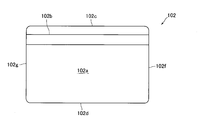
- a card 102 in which a magnetic stripe 102 b is formed on the back surface 102 a of the card 102.
- the magnetic stripe 102 b is formed at a predetermined position in the short direction of the card 102 with respect to one end face 102 c in the short direction of the card 102, and the other in the short direction of the card 2.
- the distance between the end face 102d and the magnetic stripe 102b is significantly longer than the distance between the end face 102c and the magnetic stripe 102b.
- skimming can be prevented when the card insertion / ejection unit described in Patent Document 1 is installed in front of the card reader.
- the card 102 shown in FIG. 11 is processed in the card reader in which the card insertion / ejection unit described in Patent Document 1 is installed in the front.
- a magnetic head is disposed inside the card reader at a position where the magnetic stripe 102b of the card 102 sent in the correct direction from the card insertion / ejection unit passes, and the card 102 is sent to the card reader in the correct direction.
- the card 102 can be processed by the card reader.
- the card 102 is sent to the card reader from one end surface 102f side in the longitudinal direction of the card 102 with the front surface 102e of the card 102 facing upward, Suppose that it is a case where it is sent.
- the card 102 inserted so that the short direction of the card 102 and the insertion direction of the card 102 coincide with each other by a card rotation mechanism in a certain direction. Just turning. Therefore, for example, as shown in FIG. 12A, when the card 102 is inserted into the card insertion / ejection section from the end face 102d side with the front face 102e facing upward, the counterclockwise of FIG. As shown in FIG. 12B, the card 102 can be fed into the card reader from the end face 102f side by rotating the card 102 in the turning direction (counterclockwise) by 90 °. That is, in this case, since the card 102 can be sent to the card reader in the correct direction, the card 102 can be processed by the card reader.
- the card 102 in a direction that cannot be processed by the card reader may be sent to the card reader.
- the card 102 sent to the card reader is returned to the card insertion / ejection unit and rotated by the card rotation mechanism, and then the card is inserted.
- the card 102 must be ejected from the ejection unit and inserted again into the card insertion / ejection unit in the correct orientation. Therefore, if the card 102 that cannot be processed by the card reader is sent to the card reader, it takes time to process the card.
- an object of the present invention is to provide a card insertion / ejection mechanism installed in front of a card reader that conveys and processes a card so that the longitudinal direction of the card formed in a substantially rectangular shape matches the card conveyance direction.
- Card insertion that can prevent skimming and can send a card in a direction that can be processed by the card reader to the card reader regardless of the orientation of the card inserted into the card insertion / ejection mechanism It is to provide a discharge mechanism.
- the subject of this invention is providing the card processing apparatus provided with this card insertion discharge mechanism.
- the card insertion / ejection mechanism of the present invention is provided in front of a card reader that transports and processes cards so that the longitudinal direction of the card formed in a substantially rectangular shape matches the card transport direction.
- a card insertion / ejection mechanism installed in the card, and a card insertion slot through which a card can be inserted in a state where the short side direction of the card and the card conveyance direction coincide with each other, and the card inserted from the card insertion slot pass therethrough.
- a second insertion detection mechanism that detects that the card has been inserted into the card insertion slot so that the short side direction of the card and the card conveyance direction coincide with each other by detecting both ends of the card;
- a magnetic data detection mechanism for detecting that magnetic data is recorded in the air stripe, and a card inserted from the card insertion slot so that the short side direction of the card and the card transport direction coincide with the longitudinal direction of the card.
- a card rotation mechanism for rotating the card so as to coincide with the card conveyance direction, a card conveyance mechanism for conveying the card inserted from the card insertion slot, and a control unit for the card insertion / ejection mechanism, Based on at least the detection result of the second insertion detection mechanism, it is determined whether or not a card has been inserted into the card insertion slot so that the short direction of the card matches the card transport direction, and the short of the card When a card is inserted into the card slot so that the hand direction matches the card transport direction, the front / back orientation is correct based at least on the detection result of the magnetic data detection mechanism.
- the control unit determines whether or not the card has been inserted into the card insertion slot and whether the card has been inserted into the card insertion slot from one end side or the other end side of the card in the short direction of the card. If the card is inserted into the card insertion slot so that the short side of the card matches the card transport direction and the front and back are in the correct orientation, the control unit The card transport mechanism is activated, and the card is transported and taken up to a rotation position where the card is rotated by the card rotation mechanism, and at the rotation direction and / or rotation angle based on the determination result of the card insertion direction.
- the control unit When the card is rotated by controlling the card rotation mechanism and the card is inserted into the card insertion slot so that the longitudinal direction of the card matches the card transport direction, or the front and back are reversed
- the control unit When the card is inserted into the card insertion slot in the state of the card, the control unit maintains the stopped state of the card transport mechanism and does not take in the card.
- the card insertion / ejection mechanism of the present invention is a card reader that conveys and processes a card so that the longitudinal direction of the card formed in a substantially rectangular shape matches the card conveyance direction.
- a card insertion / ejection mechanism installed in front of the card, wherein a card insertion slot into which the card can be inserted in a state where the short side direction of the card is coincident with the card conveyance direction, and the card inserted from the card insertion slot
- a second insertion detection mechanism for detecting that the card has been inserted into the card insertion slot so that the short side direction of the card and the card conveyance direction coincide with each other by detecting both ends of the card in the direction;
- Two metal detection mechanisms that detect that the external connection terminal of the IC chip is formed on the card, and the card inserted from the card insertion slot so that the short side direction of the card and the card transport direction coincide with each other.
- a card rotation mechanism for rotating the card so that the longitudinal direction of the card and the card conveyance direction coincide with each other; a card conveyance mechanism for conveying the card inserted from the card insertion slot; and a controller for the card insertion / ejection mechanism.
- One of the two metal detection mechanisms is configured such that the card is inserted into the card insertion slot from one end surface side of the card in the first direction with the correct orientation of the front and back in the first direction.
- the other metal detection mechanism of the two metal detection mechanisms is in a state where the front and back sides are correct and the short side of the card in the first direction.
- the card is disposed at a position through which the external connection terminal passes when the card is inserted into the card insertion slot from the other end surface side of the card, and the controller is configured to control the short side of the card based on at least the detection result of the second insertion detection mechanism. And whether the card is inserted into the card insertion slot so that the direction of the card and the card transport direction coincide with each other.
- the control unit activates the card transport mechanism and rotates the card by the card rotation mechanism.
- the card is conveyed to the rotation position and taken in, and the card is rotated by controlling the card rotation mechanism at the rotation direction and / or rotation angle based on the determination result of the card insertion direction.
- the control unit when a card is inserted into the card insertion slot so that the longitudinal direction of the card coincides with the card conveyance direction, the control unit maintains the card conveyance mechanism in a stopped state. Is not captured. Therefore, in the present invention, even if a skimming magnetic head is attached to the card insertion / ejection mechanism, skimming by the skimming magnetic head can be prevented.
- the control unit when the card is inserted into the card insertion slot so that the short side direction of the card coincides with the card conveying direction and the front and back directions are correct, the control unit The mechanism is activated, the card is taken in to the rotation position where the card is rotated by the card rotation mechanism, and the card rotation mechanism is controlled by the rotation direction and / or rotation angle based on the determination result of the card insertion direction. Then the card is rotated. Therefore, in the present invention, if the card is inserted into the card insertion slot so that the short direction of the card coincides with the card transport direction and the front and back directions are correct, the short direction of the card is reduced.
- the card rotation mechanism is appropriately controlled based on the result of determining the card insertion direction, and the card reader can perform processing. It is possible to rotate the card. In other words, in the present invention, if the card is inserted into the card insertion slot so that the short side direction of the card coincides with the card transport direction and the front and back directions are correct, the short side direction of the card is reduced. Regardless of whether the card is inserted into the card insertion slot from either the end face side or the other end face side, the card can be sent to the card reader after the card is rotated in a direction that allows processing by the card reader.
- the control unit maintains the stopped state of the card transport mechanism and does not take in the card. Therefore, in the present invention, a card whose front and back are reversed is not sent to the card reader. Furthermore, in the present invention, when a card is inserted into the card insertion slot so that the longitudinal direction of the card coincides with the card conveying direction, the control unit keeps the card conveying mechanism stopped and takes in the card. Absent.
- the present invention it is possible to prevent a card in a direction that cannot be processed by the card reader from being sent to the card reader. That is, according to the present invention, it is possible to send a card in a direction that can be processed by the card reader to the card reader regardless of the direction in which the card is inserted into the card insertion / ejection mechanism.
- control unit determines the orientation of the front and back based on at least one of the detection result of the first insertion detection mechanism and the detection result of the second insertion detection mechanism and the detection result of the magnetic data detection mechanism. It is determined whether or not a card has been inserted into the card insertion slot in a correct state, and the card insertion direction is determined.
- the card insertion / ejection mechanism includes a metal detection mechanism that detects that the external connection terminal of the IC chip is formed on the card, and the metal detection mechanism is a short direction of the card in the first direction. Is arranged at a position where the external connection terminal passes when the card is inserted into the card insertion slot so that the card conveying direction coincides with the card conveyance direction, and the control unit at least detects the detection result of the magnetic data detection mechanism and the metal detection mechanism. Based on the detection result, it may be determined whether or not a card has been inserted into the card insertion slot in a state where the front and back directions are correct, and the card insertion direction may be determined.
- control unit detects at least one of the detection result of the first insertion detection mechanism and the detection result of the second insertion detection mechanism, the detection result of the magnetic data detection mechanism, and the detection result of the metal detection mechanism. Based on the above, it is determined whether or not a card has been inserted into the card insertion slot in a state where the front and back directions are correct, and the card insertion direction is determined.
- the card insertion / ejection mechanism includes a shutter member that is movable between a closed position that closes the card passage path and an open position that opens the card passage path.
- a shutter member that is movable between a closed position that closes the card passage path and an open position that opens the card passage path.
- the card rotating mechanism rotates with the first direction as an axis direction of rotation and drives the two belts arranged in an annular manner with a gap in the first direction and the two belts.
- the belt drive mechanism includes two belts in a first drive state in which the two belts rotate in the same direction and in a second drive state in which the two belts rotate in opposite directions.
- at least a part of the card transport mechanism is composed of two belts and a belt drive mechanism.
- the card rotates.
- the card is preferably conveyed. If comprised in this way, since a card rotation mechanism and a card
- the card rotation mechanism includes a first pad roller and a second pad roller that are disposed opposite to the belt and biased toward the belt, and a retraction mechanism that retracts the first pad roller in a direction away from the belt.
- the first pad roller is disposed on each end of the belt in the card transport direction
- the second pad roller is disposed on each end of the belt in the card transport direction.
- the retracting mechanism is preferably disposed between the first pad roller and the first pad roller when the two belts rotate in opposite directions. If comprised in this way, at the time of conveyance of the card
- the belt drive mechanism includes two drive pulleys to which each of the two belts is engaged, and a common motor for rotating the two drive pulleys. It is preferable that they are connected via a differential gear. With this configuration, even when two drive pulleys are connected to a common motor, the two belts are rotated in the same direction, and the two belts are rotated in opposite directions. It becomes possible to make it. Therefore, the configuration of the belt drive mechanism can be simplified as compared with the case where two motors for individually rotating the two drive pulleys are provided.
- the card insertion / ejection mechanism includes a second metal detection mechanism for detecting that the external connection terminal of the IC chip is formed on the card, and the second metal detection mechanism is a card reader in the first direction.
- the card is placed in a position where the external connection terminal passes when a card with the correct front / back orientation and the correct insertion orientation is transported, and the magnetic data detection mechanism is inserted with the front / back orientation correct in the card thickness direction.
- the magnetic stripe is arranged on the side where the magnetic stripe is formed when the card is inserted into the mouth, and the card in the first direction when the card reader is transported by the card reader with the correct orientation of the front and back.
- the control unit is disposed at a passing position, and the control unit is configured to detect at least one of the detection result of the first insertion detection mechanism and the detection result of the second insertion detection mechanism. Based on the detection result of the second metal detection mechanism or on the basis of the detection result of the second metal detection mechanism, the card is in a state where a card reader is carrying the card with the correct front / back orientation and the correct insertion orientation. It is determined whether or not a card has been inserted into the insertion slot, and based on the detection result of the magnetic data detection mechanism, it is determined whether or not magnetic data is recorded on the card.
- the control unit preferably activates the card transport mechanism and transports and captures the card.
- the card insertion / ejection mechanism includes a second metal detection mechanism that detects that an external connection terminal is formed on the card, and a magnetic that detects that magnetic data is recorded on the magnetic stripe of the card.
- the second metal detection mechanism is arranged at a position through which the external connection terminal passes when the card reader transports a card in which the front and back directions are correct and the insertion direction is correct in the first direction
- the magnetic data detection mechanism is arranged on the side where the magnetic stripe is formed when the card is inserted into the card insertion slot with the correct front and back orientation in the card thickness direction. It is placed at the position where the magnetic stripe passes when a card with the correct orientation of the front and back and the correct orientation is conveyed by the reader.
- the control unit is preferably incorporate start the card conveyance mechanism conveys the card.
- the card insertion / ejection mechanism includes a light emitting unit arranged around the card insertion slot, and the control unit inserts the card into the card insertion slot so that the longitudinal direction of the card coincides with the card conveyance direction. If the card is inserted, or if a card is inserted into the card insertion slot with the front and back facing in opposite directions, it is preferable that the light emitting portion is illuminated. If comprised in this way, it will become possible to notify a user that the card
- the card insertion / ejection mechanism of the present invention can be used in a card processing apparatus including a card reader.
- this card processing device it is possible to send a card in a direction that can be processed by the card reader to the card reader regardless of the orientation of the card insertion / ejection mechanism, while preventing skimming.
- the card insertion / ejection mechanism of the present invention is installed in front of a card reader that transports and processes cards so that the longitudinal direction of the card formed in a substantially rectangular shape matches the card transport direction.
- the card insertion / ejection mechanism it is possible to prevent skimming and to send the card to the card reader in a direction that can be processed by the card reader no matter what orientation the card is inserted into the card insertion / ejection mechanism. It becomes possible.
- the card processing device of the present invention while preventing skimming, a card in a direction that can be processed by the card reader can be sent to the card reader regardless of the direction in which the card is inserted into the card insertion / ejection mechanism. It becomes possible.
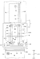
- FIG. 1 It is a schematic plan view of the card processing apparatus concerning embodiment of this invention.
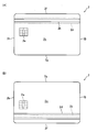
- A) is a top view which shows the front surface of the card
- B) is a top view which shows the back surface of the card
- FIG. It is a top view for demonstrating the structure of the front-end side part of the card insertion discharge mechanism shown in FIG.
- FIG. 1 It is a block diagram of the structure relevant to the card taking-in control in the card insertion discharge mechanism shown in FIG. It is a figure which shows an example of the output signal of the metal detection mechanism shown in FIG. It is a figure for demonstrating the insertion pattern of a card
- FIG. 1 is a schematic plan view of a card processing apparatus 1 according to an embodiment of the present invention.
- 2A is a plan view showing the front surface 2a of the card 2 shown in FIG. 1
- FIG. 2B is a plan view showing the back surface 2c of the card 2 shown in FIG.
- the card processing device 1 of this embodiment is a device for reading data recorded on the card 2 and recording data on the card 2, and is used by being mounted on a predetermined host device such as an ATM. .
- the card processing device 1 includes a card reader 3 and a card insertion / ejection mechanism 4 installed in front of the card reader 3.
- a card insertion slot 5 into which the card 2 is inserted is formed in the card insertion / ejection mechanism 4.
- a light emitting section 7 (see FIG. 3) in which LEDs and the like are arranged is provided inside the card insertion / ejection mechanism 4 is formed a card passage 6 through which the card 2 inserted from the card insertion slot 5 passes.
- the card 2 inserted into the card insertion slot 5 is taken into the card insertion / ejection mechanism 4, then sent out from the card insertion / ejection mechanism 4 and taken into the card reader 3.
- the card 2 ejected from the card reader 3 is taken into the card insertion / ejection mechanism 4 and then ejected from the card insertion slot 5.
- the card 2 processed by the card processing apparatus 1 is a substantially rectangular vinyl chloride card having a thickness of about 0.7 to 0.8 mm.
- This card 2 is a magnetic card compliant with international standards and JIS standards. As shown in FIG. 2, a magnetic stripe 2b is formed on the front surface 2a of the card 2, and the back surface 2c of the card 2 is formed on the back surface 2c. A magnetic stripe 2d is formed.
- the card 2 is a contact-type IC card that complies with international standards, and the card 2 contains an IC chip. On the front surface 2a of the card 2, an external connection terminal 2e of an IC chip is formed.
- the magnetic stripes 2b and 2d are formed along the longitudinal direction of the card 2 formed in a substantially rectangular shape.
- the magnetic stripes 2b and 2d are formed at predetermined positions in the short direction of the card 2 with reference to one end face (one end face) 2f in the short direction of the card 2.
- the distance between the other end face (the other end face) 2g in the direction and the magnetic stripes 2b and 2d is significantly longer than the distance between the one end face 2f of the card 2 and the magnetic stripes 2b and 2d.
- the magnetic stripe 2 b and the magnetic stripe 2 d overlap when viewed from the thickness direction of the card 2.
- the external connection terminal 2 e is formed at a predetermined position based on one end face (one end face) 2 h in the longitudinal direction of the card 2 and one end face 2 f in the short direction of the card 2.
- the card reader 3 is formed with a card insertion slot into which the card 2 sent out from the card insertion / ejection mechanism 4 is inserted.
- a card transport path through which the card 2 inserted from the card insertion slot is transported is formed inside the card reader 3.
- the card reader 3 contacts the external connection terminal 2e with a magnetic head for reading the magnetic data recorded in the magnetic stripes 2b and 2d and recording the magnetic data on the magnetic stripes 2b and 2d, and communicates data. IC contact springs for performing.
- the card reader 3 includes a card transport mechanism that transports the card 2 in the card transport path. The card reader 3 transports the card 2 so that the longitudinal direction of the card 2 formed in a substantially rectangular shape matches the transport direction of the card 2 and executes a predetermined process on the card 2.
- the X direction shown in FIG. 1 matches the transport direction of the card 2 in the card reader 3. Further, the X2 direction of the X direction coincides with the insertion direction of the card 2 into the card insertion slot 5, and the X1 direction of the X direction coincides with the discharge direction of the card 2 from the card insertion slot 5.
- the Z direction orthogonal to the X direction coincides with the thickness direction of the card 2 inserted into the card insertion slot 5, and the thickness of the card 2 passing through the card passing path 6 and the card transport path of the card reader 3. Match the direction.
- the Y direction orthogonal to the X direction and the Z direction coincides with the width direction of the card 2 inserted into the card insertion slot 5.
- the X direction is “front-rear direction”, the Y direction is “left-right direction”, and the Z direction is “up-down direction”.
- the X1 direction side is the “front (front)” side
- the X2 direction side is the “back (rear) side”
- the Y1 direction side is the “right” side
- the Y2 direction side is the “left” side.
- the Z1 direction side is the “upper” side
- the Z2 direction side is the “lower” side.
- the card processing apparatus 1 is installed so that the Z direction (up and down direction) coincides with the vertical direction (the direction of gravity).
- the Y direction (left-right direction) of the present embodiment is a first direction orthogonal to the thickness direction of the card 2 and the conveyance direction of the card 2.
- FIG. 3 is a side view for explaining the configuration of the front end portion of the card insertion / ejection mechanism 4 shown in FIG.
- FIG. 4 is a front view for explaining the configuration of the front end portion of the card insertion / ejection mechanism 4 shown in FIG.
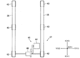
- FIG. 5 is a plan view for explaining the configuration of the card rotation transport mechanism 16 shown in FIG.
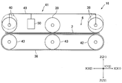
- FIG. 6 is a side view for explaining the configuration of the card rotation transport mechanism 16 shown in FIG.
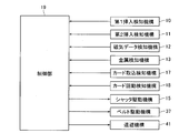
- FIG. 7 is a block diagram of a configuration related to the card 2 take-in control in the card insertion / ejection mechanism 4 shown in FIG.
- FIG. 8 is a diagram illustrating an example of an output signal of the metal detection mechanism 13 illustrated in FIG.
- FIG. 9 is a diagram for explaining an insertion pattern of the card 2 when the card 2 is inserted into the card insertion slot 5 shown in FIG. 1 in a state where the short side direction and the front-rear direction of the card 2 coincide with each other. .
- the card insertion / ejection mechanism 4 includes a first insertion detection mechanism 10 that detects that the card 2 is inserted into the card insertion slot 5, and a short direction and front / rear direction of the card 2 by detecting both ends of the card 2 in the left / right direction.
- a magnetic data detection mechanism 12 and a metal detection mechanism 13 for detecting that the external connection terminal 2e is formed on the card 2 are provided.
- the first insertion detection mechanism 10, the second insertion detection mechanism 11, the magnetic data detection mechanism 12, and the metal detection mechanism 13 are arranged on the front end side of the card insertion / ejection mechanism 4.
- the left and right widths of the card insertion slot 5 are wider than the width in the longitudinal direction of the card 2, and the card 2 is inserted into the card insertion slot 5 in a state where the short side direction and the front-rear direction of the card 2 are aligned. It can be inserted. That is, the left and right widths of the card insertion / ejection mechanism 4 are wider than the width in the longitudinal direction of the card 2. The front and rear lengths of the card insertion / ejection mechanism 4 are longer than the width of the card 2 in the longitudinal direction. Inside the card insertion / ejection mechanism 4, the card 2 inserted in the card insertion slot 5 is rotated so that the longitudinal direction of the card 2 matches the longitudinal direction so that the lateral direction of the card 2 matches the longitudinal direction. It is possible to move.
- the card insertion / ejection mechanism 4 includes a shutter member 14 that is movable between a closed position that closes the card passage path 6 and an open position that opens the card passage path 6, and a shutter drive mechanism 15 that drives the shutter member 14. (See FIG. 7) and the card 2 inserted in the card insertion slot 5 is rotated so that the longitudinal direction of the card 2 and the front-rear direction coincide with each other so that the short side direction and the front-rear direction of the card 2 coincide with each other.
- a card rotation transport mechanism 16 for transporting the card 2 inserted from the card insertion slot 5 is provided.
- the shutter member 14, the shutter drive mechanism 15, and the card rotation transport mechanism 16 are disposed on the back side of the first insertion detection mechanism 10, the second insertion detection mechanism 11, the magnetic data detection mechanism 12, and the metal detection mechanism 13. .
- the card insertion / ejection mechanism 4 moves the card 2 to a rotation position 2A (see FIG. 1) for rotating the card 2 inserted from the card insertion slot 5 so that the short side direction and the front-rear direction of the card 2 coincide with each other.
- a card rotation detection mechanism 18 that detects that the card 2 has rotated until the longitudinal direction of the card 2 coincides with the front-rear direction at the rotation position 2A.
- the first insertion detection mechanism 10, the second insertion detection mechanism 11, the magnetic data detection mechanism 12, the metal detection mechanism 13, the shutter drive mechanism 15, the card insertion detection mechanism 17, and the card rotation detection mechanism 18 are the card insertion / ejection mechanism 4.
- the control unit 19 is electrically connected.
- a belt driving mechanism 37 and a retracting mechanism 41, which will be described later, constituting the card rotation conveyance mechanism 16 are also electrically connected to the control unit 19.
- the control unit 19 may be provided separately from the control unit of the card reader 3, or the control unit 19 may also serve as the control unit of the card reader 3.
- the first insertion detection mechanism 10 has a roller 23 that can be rotated with the left-right direction being the axial direction of rotation, a fixed shaft 24 that rotatably holds the roller 23, and a fixed shaft 24.
- a shaft holding member 25, a fixed shaft 26 that rotatably holds the shaft holding member 25, and a sensor 27 that detects the movement of the shaft holding member 25 are provided.
- the first insertion detection mechanism 10 is electrically connected to the control unit 19.
- the sensor 27 is electrically connected to the control unit 19.
- the first insertion detection mechanism 10 may be, for example, a transmissive optical sensor having a light emitting element and a light receiving element that are disposed so as to sandwich the card passage 6 in the vertical direction.
- the sensor 27 is a transmissive optical sensor having a light emitting element and a light receiving element arranged to face each other.
- the fixed shaft 26 is fixed to the frame of the card insertion / ejection mechanism 4 so that the axial direction of the fixed shaft 26 coincides with the left-right direction.
- the shaft holding member 25 is disposed below the card passage 6.
- the shaft holding member 25 is formed with a flat light-shielding portion 25 a for blocking light traveling from the light emitting element to the light receiving element of the sensor 27.
- the fixed shaft 24 is fixed to the upper end side of the shaft holding member 25.
- the roller 23 By rotating the shaft holding member 25 with the fixed shaft 26 as the center of rotation, the roller 23 closes the card passing path 6 (the position shown in FIG. 4A) and the card passing path 6. It is movable between an open position (a position shown in FIG. 4B) that retracts downward and opens the card passage 6.
- the shaft holding member 25 is urged in a direction in which the roller 23 rises by an urging member such as a spring (not shown). That is, the roller 23 is urged toward the closed position.
- the roller 23 is disposed at the closed position, and the card passage 6 is closed.
- the light shielding portion 25 a of the shaft holding member 25 is separated from between the light emitting element and the light receiving element of the sensor 27.
- the light shielding portion 25a enters between the light emitting element and the light receiving element of the sensor 27 and blocks light from the light emitting element toward the light receiving element.
- the light shielding portion 25a enters between the light emitting element and the light receiving element of the sensor 27 and blocks light from the light emitting element toward the light receiving element.
- the roller 23 When the card 23 is inserted into the card insertion slot 5 so that the longitudinal direction of the card 2 coincides with the front-rear direction, the roller 23 is inserted regardless of the position in the left-right direction. Is disposed at a position in contact with the roller 23. Therefore, not only when the card 2 is inserted into the card insertion slot 5 so that the short side direction and the front-back direction of the card 2 match, but also the card insertion slot so that the longitudinal direction of the card 2 matches the front-back direction. Even when the card 2 is inserted into 5, the roller 23 moves from the closed position to the open position.
- the second insertion detection mechanism 11 is capable of rotating each of the two detection levers 29 and the two detection levers 29 arranged on the left and right ends of the card insertion / ejection mechanism 4.
- Two fixed shafts 30 to be held and two sensors 31 for detecting movements of the two detection levers 29 are provided.
- the second insertion detection mechanism 11 is electrically connected to the control unit 19.
- the sensor 31 is electrically connected to the control unit 19.
- the second insertion detection mechanism 11 may be, for example, a transmissive optical sensor having a light emitting element and a light receiving element that are disposed so as to sandwich the card passage 6 in the vertical direction. This optical sensor is disposed on both the left and right ends of the card insertion / ejection mechanism 4.
- the sensor 31 is a transmissive optical sensor that includes a light emitting element and a light receiving element that are opposed to each other.
- the fixed shaft 30 is fixed to the frame of the card insertion / ejection mechanism 4 so that the axial direction of the fixed shaft 30 coincides with the front-rear direction.
- the detection lever 29 includes a card contact portion 29a that can be brought into contact with both ends of the card 2 in the left-right direction of the card 2 from the left and right ends of the card transport path 6 and from the light emitting element of the sensor 31 to the light receiving element. And a light-shielding portion 29b for shielding light traveling there.
- the card contact portion 29 a is disposed at substantially the same position as the roller 23.
- the upper end side of the card contact portion 29a is rotatably held by the fixed shaft 30.
- the detection lever 29 is urged by an urging member such as a spring (not shown) so that the card contact portion 29a moves inward in the left-right direction.
- the card contact portion 29a is arranged in the card passage 6 by the biasing force of the biasing member.
- the light shielding portion 29b is disposed between the light emitting element and the light receiving element of the sensor 31, and light from the light emitting element to the light receiving element is blocked.
- the card 2 is inserted into the card insertion slot 5 so that the short side direction and the front and rear direction of the card 2 coincide with each other. Detected.
- the card 2 is inserted into the card insertion slot 5 so that the longitudinal direction of the card 2 matches the longitudinal direction, only one of the two detection levers 29 rotates and the other The detection lever 29 does not rotate, or both of the two detection levers 29 do not rotate. Therefore, when the card 2 is inserted into the card insertion slot 5 so that the longitudinal direction of the card 2 coincides with the front-rear direction, only one of the two sensors 31 receives light from the light emitting element.
- the element receives light, or the light receiving element does not receive light from the light emitting element in both of the two sensors 31.
- the magnetic data detection mechanism 12 is, for example, a fluxgate sensor including an excitation coil, a detection coil, and a core around which the excitation coil and the detection coil are wound.
- the magnetic data detection mechanism 12 is disposed at substantially the same position as the roller 23 in the front-rear direction. Moreover, the magnetic data detection mechanism 12 is arrange
- the magnetic data detection mechanism 12 may be disposed only at one place on the upper side or the lower side of the card passage 6.
- the magnetic data detection mechanism 12 may be a magnetic head (pre-head) or a magnetic impedance sensor (MI sensor) that detects magnetic data using magnetic impedance.
- pre-head pre-head
- MI sensor magnetic impedance sensor
- the metal detection mechanism 13 is a magnetic sensor including an excitation coil, a detection coil, and a core around which the excitation coil and the detection coil are wound.
- the metal detection mechanism 13 detects a change in the magnetic field generated by the excitation coil with the detection coil and detects the external connection terminal 2e.
- the metal detection mechanism 13 is disposed at substantially the same position as the magnetic data detection mechanism 12 in the front-rear direction. Further, the metal detection mechanism 13 is arranged on the side where the external connection terminal 2e is formed when the card 2 is inserted into the card insertion slot 5 with the front and back facing in the vertical direction. In this embodiment, when the card 2 is inserted into the card insertion slot 5 with the front and back sides being correct, the front surface 2a faces upward, and the metal detection mechanism 13 is disposed above the card passage 6. Has been.
- the metal detection mechanism 13 allows the external connection terminal 2e to pass when the card 2 is inserted into the card insertion slot 5 with the front and back directions being correct and the insertion direction in the short direction of the card 2 being correct in the left-right direction. It is arranged at the position to do.
- the card 2 when the card 2 is inserted into the card insertion slot 5 with the front and back sides being correct and the insertion direction in the short direction of the card 2 being correct, as shown in FIG.
- the card 2 is inserted into the card insertion slot 5 from the end surface 2f side in the short direction of the card 2 with the 2a facing upward.
- the external connection terminal 2 e passes when the card 2 is inserted into the card insertion slot 5 from the one end surface 2 f side with the front surface 2 a facing upward in the left-right direction. Placed in position. That is, the metal detection mechanism 13 is arranged on the left end side of the card passage 6. As shown in FIG. 9C, when the card 2 is inserted into the card insertion slot 5 from the other end surface 2g side in the short direction of the card 2 with the back surface 2c facing upward, In the direction, the external connection terminal 2e passes through the position where the metal detection mechanism 13 is disposed.
- the metal detection mechanism 13 is disposed on the upper side of the card passage 6, as shown in FIG. 9A, the front surface 2 a faces upward and the one end surface 2 f.
- the peak value of the output signal SG1 (see FIG. 8) of the metal detection mechanism 13 when the card 2 is inserted into the card insertion slot 5 from the side is directed upward. It becomes higher than the peak value of the output signal SG2 (see FIG. 8) of the metal detection mechanism 13 when the card 2 is inserted into the card insertion slot 5 from the one end surface 2g side.
- a threshold value th1 is set as shown in FIG. 8, and the positions where the metal detection mechanisms 13 are arranged in the left-right direction are externally connected as shown in FIGS. 9A and 9C.
- the metal detection mechanism 13 detects the external connection terminal 2e.
- FIGS. 9B and 9C when the external connection terminal 2e does not pass through the position where the metal detection mechanism 13 is disposed in the left-right direction, the metal detection mechanism 13 causes the external connection terminal 2e. Is not detected.
- the shutter member 14 is disposed behind the roller 23. Further, when the shutter member 14 is in contact with the shutter member 14 at the closed position, the back end of the card 2 inserted into the card insertion slot 5 so that the short side direction and the front-rear direction of the card 2 coincide with each other, The front end of the card 2 is arranged so as to protrude to the front side of the card insertion slot 5.
- the shutter drive mechanism 15 includes a drive source such as a solenoid and moves the shutter member 14 between a closed position and an open position. As described above, the shutter drive mechanism 15 is electrically connected to the control unit 19. Specifically, the drive source is electrically connected to the control unit 19.
- the card rotation conveyance mechanism 16 includes two annular belts 35 and 36 that are arranged at intervals in the left-right direction, a belt drive mechanism 37 that drives the two belts 35 and 36, a belt 35, A pad roller 38 to 40 that is disposed opposite to the belt 36 and biased toward the belt 35, 36, and a retreat mechanism 41 (see FIG. 6) for retracting the pad roller 38, 40 away from the belt 35, 36. It has.
- the belts 35 and 36 are disposed so as to rotate with the left-right direction as the axial direction of rotation. Moreover, the belts 35 and 36 are arrange
- the distance between the belt 35 and the belt 36 in the left-right direction is narrower than the width in the short direction of the card 2 as shown in FIG. In this embodiment, the belt 35 is disposed on the right side, and the belt 36 is disposed on the left side.
- the belt drive mechanism 37 includes a drive pulley 42 and two driven pulleys 43 around which the belt 35 is bridged, a drive pulley 42 and two driven pulleys 43 around which the belt 36 is bridged, A common motor 44 that rotates the drive pulleys 42 and a power transmission mechanism 45 that transmits the power of the motors 44 to the two drive pulleys 42 are provided.
- the belt drive mechanism 37 is electrically connected to the control unit 19. Specifically, the motor 44 is electrically connected to the control unit 19.
- the power transmission mechanism 45 includes a differential gear 46. That is, the two drive pulleys 42 and the motor 44 are connected via a differential gear 46, and the belt drive mechanism 37 includes a first drive state in which the belt 35 and the belt 36 rotate in the same direction, and the belt In the second driving state in which the belt 35 and the belt 36 rotate in opposite directions, the two belts 35 and 36 can be driven.
- the card rotation transport mechanism 16 includes the center of the card 2 inserted in the card insertion slot 5 so that the short side direction of the card 2 matches the front-rear direction and the card insertion / discharge mechanism 4. The card 2 conveyed by the card rotation conveyance mechanism 16 is rotated until the center in the front-rear direction substantially coincides.
- the position where the center in the short direction of the card 2 and the center in the front-rear direction of the card insertion / ejection mechanism 4 substantially coincide with each other is a rotation position 2A where the card 2 is rotated.
- the card rotation conveyance mechanism 16 of this embodiment is configured so that the longitudinal direction of the card 2 matches the longitudinal direction of the card 2 inserted into the card insertion slot 5 so that the short direction of the card 2 matches the longitudinal direction.
- a card transport mechanism that transports the card 2 inserted from the card insertion slot 5. It should be noted that the length of the card passing path 6 in the front-rear direction is such that the card 2 does not protrude beyond the card insertion slot 5 when the card 2 arranged at the rotation position 2A is rotated. Is set.
- the pad rollers 38 to 40 are arranged at a predetermined interval in the front-rear direction.
- the pad rollers 38 to 40 are arranged in this order from the near side to the far side.
- the pad roller 38 is disposed so as to face the driving pulley 42 from above
- the pad rollers 39 and 40 are disposed so as to face the driven pulley 43 from above. That is, the pad rollers 38 and 40 are disposed on both ends of the belts 35 and 36 in the front-rear direction, and the pad roller 39 is disposed between the pad roller 38 and the pad roller 40 in the front-rear direction.
- the pad roller 39 is disposed at the center position between the pad roller 38 and the pad roller 40 in the front-rear direction.
- the pad rollers 38 and 40 are first pad rollers
- the pad roller 39 is a second pad roller.
- the retracting mechanism 41 includes a connecting lever 49 that connects the pad roller 38 and the pad roller 40, and a drive source 50 such as a solenoid that moves the connecting lever 49 up and down.
- the retraction mechanism 41 is electrically connected to the control unit 19.
- the drive source 50 is electrically connected to the control unit 19.
- the card take-in detection mechanism 17 is, for example, a transmissive optical sensor that includes a light emitting element and a light receiving element that face each other so as to sandwich the card passage 6 in the vertical direction.
- This card taking-in detection mechanism 17 is arrange
- the card rotation detection mechanism 18 is, for example, a transmissive optical sensor that includes a light emitting element and a light receiving element that are disposed so as to sandwich the card passage 6 in the vertical direction.
- the card rotation detection mechanisms 18 are arranged at two locations on the card passage 6 with a space in the front-rear direction. Specifically, a position that sandwiches the front end side portion of the card 2 that is rotated so that the longitudinal direction and the front-rear direction of the card 2 coincide with each other at the rotation position 2A and a position that sandwiches the back end side portion of the card 2
- the card rotation detection mechanism 18 is disposed at two locations.
- the interval between the two card rotation detection mechanisms 18 in the front-rear direction is wider than the width of the card 2 in the short direction, and the rotation position 2A is such that the short direction of the card 2 matches the front-rear direction.
- the front end side portion and the back end side portion of the card 2 arranged in the card 2 are not detected by the card rotation detection mechanism 18.
- the card rotation detection mechanism 18 is arrange
- the control unit 19 Based on the detection result of the second insertion detection mechanism 11 or based on the detection result of the first insertion detection mechanism 10 and the detection result of the second insertion detection mechanism 11, the control unit 19 performs the short direction of the card 2. It is determined whether or not the card 2 has been inserted into the card insertion slot 5 so that the front and rear directions coincide with each other. Specifically, when the light from the light emitting element is received by the light receiving element in the two sensors 31, or the light from the light emitting element to the light receiving element is blocked in the sensor 27, the control unit 19 blocks two light. When the light from the light emitting element is received by the light receiving element in the sensor 31, it is determined that the card 2 is inserted into the card insertion slot 5 so that the short side direction of the card 2 matches the front-rear direction.
- the light from the light emitting element to the light receiving element is blocked by the sensor 27, but the light from the light emitting element is received by the light receiving element only in one of the two sensors 31.
- the card 2 is inserted into the card insertion slot 5 so that the longitudinal direction of the card 2 coincides with the front-rear direction.
- the control unit 19 detects the detection result of the first insertion detection mechanism 10 and the second insertion. Based on at least one of the detection results of the detection mechanism 11, the detection result of the magnetic data detection mechanism 12, and the detection result of the metal detection mechanism 13, the card 2 is inserted into the card insertion slot 5 with the front and back directions being correct. It is determined whether or not the card 2 has been inserted, and whether the card 2 has been inserted into the card insertion slot 5 from one end surface 2f side or the other end surface 2g side in the short direction of the card 2 is determined. Determine the orientation.
- control unit 19 detects the first time from when the first insertion detection mechanism 10 detects the card 2 to when the magnetic data detection mechanism 12 detects magnetic data and the second insertion detection mechanism 11 to detect the card. 9 (A) to 9 (A) to (D) based on at least one of the second time from when the magnetic data detection mechanism 12 detects the magnetic data until the magnetic data detection mechanism 12 detects the magnetic data, and the detection result of the metal detection mechanism 13. In any state of D), it is determined whether or not the card 2 has been inserted into the card insertion slot 5 so that the short side direction and the front-back direction of the card 2 coincide.
- the control unit 19 determines that the card 2 is as shown in FIG. It is determined that the card is inserted into the card insertion slot 5 from the one end face 2f side with the front face 2a facing upward.
- the control unit 19 detects the card 2 as shown in FIG. 9B. It is determined that the card is inserted into the card insertion slot 5 from the other end surface 2g side with the front surface 2a facing upward.
- the control unit 19 determines that the card 2 is It is determined that the card is inserted into the card insertion slot 5 from the other end surface 2g side with the back surface 2c facing upward. Further, when the first time and / or the second time is short and the external connection terminal 2e is not detected by the metal detection mechanism 13, the control unit 19 determines that the card 2 is on the back surface as shown in FIG. It is determined that the card has been inserted into the card insertion slot 5 from the one end face 2f side with 2b facing upward.
- the shutter member 14 is disposed at the closed position before the card 2 is inserted into the card insertion / ejection mechanism 4 and closes the card passage 6. ing.
- the short side direction of the card 2 and the front / rear direction are aligned and the front / back direction is correct (that is, the front surface).
- the control unit 19 determines that the card 2 has been inserted into the card insertion slot 5 (with 2a facing upward)
- the control unit 19 activates the shutter drive mechanism 15 to move the shutter member 14 from the closed position to the open position.
- the controller 19 activates the belt drive mechanism 37 (that is, activates the card rotation conveyance mechanism 16) to convey and take in the card 2 to the rotation position 2A.
- the controller 19 determines the rotation direction and / or rotation based on the determination result of the insertion direction of the card 2 (that is, the determination result of whether the card 2 is inserted from the one end surface 2f side or the other end surface 2g side).
- the belt drive mechanism 37 is controlled by the moving angle (that is, the card rotation conveyance mechanism 16 is controlled), and the card 2 at the rotation position 2A is rotated.
- a state in which one end surface 2h in the longitudinal direction of the card 2 is disposed on the back side (that is, the other end surface (other end surface) 2j in the longitudinal direction of the card 2 is disposed on the front side.
- In the card reader 3 is the correct insertion direction of the card 2 in the front-rear direction.
- the control unit 19 moves the card 2 90 ° in the clockwise direction (clockwise) in FIG.
- the card 2 is rotated 90 ° counterclockwise in FIG.
- the control unit 19 rotates the card 2 by 90 ° in the clockwise direction, and FIG.
- the card 2 is rotated 270 ° clockwise.
- the control unit 19 rotates the card 2 270 degrees counterclockwise, and FIG. ), When the card 2 is inserted into the card insertion slot 5, the card 2 is rotated 90 ° counterclockwise.
- the card 2 is sent to the card reader 3 by the card rotation transport mechanism 16, and a predetermined process for the card 2 is executed in the card reader 3.
- the card 2 is ejected from the card reader 3.
- the discharged card 2 is transported to the rotational position 2A by the card rotational transport mechanism 16, and then the card rotational transport mechanism 16 until the short side direction and the front-rear direction of the card 2 coincide with each other at the rotational position 2A. It can be rotated.
- the card 2 is transported to the near side by the card rotation transport mechanism 16 and is ejected from the card insertion slot 5.
- the control unit 19 does not activate the shutter drive mechanism 15 and the shutter member 14 is in the closed position.
- the card 2 is not taken in while the belt drive mechanism 37 is kept stopped (that is, the card rotation transport mechanism 16 is kept stopped).
- the control unit 19 causes the light emitting unit 7 provided around the card insertion slot 5 to shine.
- the control unit 19 controls the belt drive mechanism 37 in the rotation direction and / or the rotation angle based on the determination result of the insertion direction of the card 2 to the rotation position 2A.
- a certain card 2 is rotated. Therefore, in this embodiment, if the card 2 is inserted into the card insertion slot 5 so that the short side direction and the front-rear direction of the card 2 coincide with each other and the front and back directions are correct, FIG.
- the card 2 is inserted into the card insertion slot 5 from the one end face 2f side as shown, the card 2 is inserted into the card insertion slot 5 from the other end face 2g side as shown in FIG. 9B.
- the card insertion slot 5 is turned upside down.
- the card 2 is not captured. Therefore, in this embodiment, the card 2 with the front and back facing in the opposite direction is not sent to the card reader 3.
- the card 2 is not taken in.
- the configuration of the card insertion / ejection mechanism 4 is simplified as compared with the case where the card rotation mechanism that rotates the card 2 and the card conveyance mechanism that conveys the card 2 are provided separately. It becomes possible.
- the retracting mechanism 41 lowers the pad rollers 38 and 40 and lowers the two belts 35 and 36 when the two belts 35 and 36 are rotated in the same direction to convey the card 2 in the front-rear direction.
- the pad rollers 38 and 40 are raised and retracted away from the belts 35 and 36. Therefore, in this embodiment, when the card 2 in which the two belts 35 and 36 rotate in the same direction is conveyed, the card 2 can be reliably conveyed using the pad rollers 38 to 40. Further, when the card 2 in which the two belts 35 and 36 are rotated in opposite directions, the pad rollers 38 and 40 are retracted to reduce the load when the card 2 is rotated. Become. Further, the card 2 can be reliably held by the pad roller 39 and the belts 35 and 36 when the card 2 is rotated.
- two drive pulleys 42 and one motor 44 are connected via a differential gear 46. Therefore, in this embodiment, even when the two drive pulleys 42 are connected to the common motor 44, the two belts 35 and 36 are rotated in the same direction, and the two belts 35 are rotated. , 36 can be rotated in opposite directions. Therefore, in this embodiment, the configuration of the belt drive mechanism 37 can be simplified as compared with the case where two motors for individually rotating the two drive pulleys 42 are provided.
- a threshold th1 for the output signal of the metal detection mechanism 13 is set so that the terminal 2e is detected.
- the second threshold th2 may be set between the peak values of the output signal SG2 of the metal detection mechanism 13 when the card 2 is inserted into the card insertion slot 5 in the state shown in FIG. 9C.
- the controller 19 determines that the card 2 has been inserted into the card insertion slot 5 in the state shown in FIG. 9B, and inserts the card in the state shown in FIG. It is determined that the card 2 has been inserted into the mouth 5.
- the control unit 19 inserts the card into the card insertion slot 5 in the state shown in FIG. 2 is inserted, and when the peak value of the output signal of the metal detection mechanism 13 exceeds the threshold th1 but is less than the second threshold th2, the card is inserted into the card insertion slot 5 in the state shown in FIG. 9C. 2 is inserted.
- the metal detection mechanism 13 is connected to the external connection terminal 2e when the card 2 is inserted into the card insertion slot 5 from the one end face 2f side with the front face 2a facing upward in the left-right direction. Is disposed at a position where the card passes, and is disposed above the card passage 6.
- the metal detection mechanism 13 has an external connection terminal when the card 2 is inserted into the card insertion slot 5 from the other end surface 2g side with the front surface 2a facing upward in the left-right direction. 2e may be disposed at a position where the card passes and may be disposed above the card passage 6.
- the control unit 19 inserts the card in the state shown in FIG.
- the state shown in FIG. 9 (C) it is determined that the card 2 has been inserted into the card insertion slot 5, the first time and / or the second time is long, and the external connection terminal 2e is not detected by the metal detection mechanism 13.
- the external connection terminal 2e passes when the metal detection mechanism 13 is inserted in the card insertion slot 5 from the one end surface 2f side with the front surface 2a facing upward in the left-right direction.
- the metal detection mechanism 13 is arranged at the position and below the card passage 6 or when the metal detection mechanism 13 is in the left-right direction with the front surface 2a facing upward and from the other end surface 2g side.
- the controller 19 It is possible to determine in any of the states shown in 9 (A) to 9 (D) whether the card 2 is inserted into the card insertion slot 5.
- the magnetic stripe 2b is formed on the front surface 2a of the card 2 and the magnetic stripe 2d is formed on the back surface 2c of the card 2, but only one of the magnetic stripe 2b or the magnetic stripe 2d is formed. It may be formed on the card 2.
- the magnetic data detection mechanism 12 is arranged at one place above the card passage 6, and when only the magnetic stripe 2 d is formed on the card 2.
- the magnetic data detection mechanism 12 is arranged at one place below the card passage 6.
- the control unit 19 detects the magnetic data by the magnetic data detection mechanism 12.
- the external connection terminal 2e is detected by the metal detection mechanism 13 it is determined that the card 2 has been inserted into the card insertion slot 5 in the state shown in FIG.
- the external connection terminal 2e is not detected by the metal detection mechanism 13 it is determined that the card 2 is inserted into the card insertion slot 5 in the state shown in FIG.
- the magnetic data is not detected by this, it is determined that the card 2 is inserted into the card insertion slot 5 in the state shown in FIG. 9C or the state shown in FIG. 9D.
- control unit 19 inserts the card 2 into the card insertion slot 5 in any state shown in FIGS. 9A to 9D based on the detection result of the magnetic data detection mechanism 12 and the detection result of the metal detection mechanism 13. It may be determined whether or not is inserted.
- the control unit 19 shows, for example, when the first time and / or the second time are short as shown in FIG. It is determined that the card 2 is inserted into the card insertion slot 5 in the state, and the card 2 is inserted into the card insertion slot 5 in the state shown in FIG. 9B when the first time and / or the second time is long.
- the control unit 19 determines whether or not the detection result of the first insertion detection mechanism 10 and the detection result of the second insertion detection mechanism 11 and the detection result of the magnetic data detection mechanism 12 are based on FIG. ) To (D), it may be determined whether the card 2 is inserted into the card insertion slot 5.
- the card insertion detection mechanism 4 may not include the metal detection mechanism 13.
- the external connection terminal 2 e may not be formed on the card 2.
- the magnetic data detection mechanism 12 may be disposed at one place below the card passage 6, or only the magnetic stripe 2 d is formed on the card 2. In this case, the magnetic data detection mechanism 12 may be disposed at one place above the card passage 6. For example, when only the magnetic stripe 2 b is formed on the card 2 and the magnetic data detection mechanism 12 is arranged at one place below the card passage 6, the control unit 19 uses the magnetic data detection mechanism 12 to When no data is detected and the external connection terminal 2e is detected by the metal detection mechanism 13, it is determined that the card 2 is inserted into the card insertion slot 5 in the state shown in FIG.
- the card 2 is inserted into the card insertion slot 5 in the state shown in FIG.
- the card 2 is inserted into the card insertion slot 5 in the state shown in FIG. 9C or the state shown in FIG. 9D. It is determined to have been.
- FIG. 10 is a schematic plan view of a card processing apparatus 1 according to another embodiment of the present invention.
- the card insertion / ejection mechanism 4 includes one metal detection mechanism 13, and the metal detection mechanism 13 has one end surface with the front surface 2 a facing upward in the left-right direction.
- the external connection terminal 2e is disposed at a position where the card 2 is inserted, and is disposed above the card passage 6.
- the card insertion / ejection mechanism 4 may include a metal detection mechanism 63 in addition to the metal detection mechanism 13, as shown in FIG.
- the metal detection mechanism 63 has a position in which the external connection terminal 2e passes when the card 2 is inserted into the card insertion slot 5 from the other end surface 2g side with the front surface 2a facing upward in the left-right direction. And at the upper side of the card passage 6.
- the control unit 19 determines that the card 2 is inserted into the card insertion slot 5 in the state shown in FIG.
- the external connection terminal 2e is detected by the detection mechanism 63
- the external detection terminal 2e is detected by the metal detection mechanisms 13 and 63.
- it is not detected it is determined that the card 2 is inserted into the card insertion slot 5 in the state shown in FIG. 9C or the state shown in FIG. 9D. That is, based on the detection results of the two metal detection mechanisms 13 and 63, the control unit 19 determines in which state shown in FIGS. 9A to 9D the card 2 is inserted into the card insertion slot 5. You may judge. In this case, the threshold th2 (see FIG. 8) is used to detect the external connection terminal 2e.
- the external connection terminal 2 e passes when the card 2 is inserted into the card insertion slot 5 from the one end face 2 f side with the front surface 2 a facing upward in the left-right direction. It may be arranged at the position and below the card passage 6. Further, in the metal detection mechanism 63, the external connection terminal 2e passes when the card 2 is inserted into the card insertion slot 5 from the other end surface 2g side with the front surface 2a facing upward in the left-right direction. It may be arranged at the position and below the card passage 6. Even in this case, the control unit 19 can insert the card 2 into the card insertion slot 5 in any state shown in FIGS. 9A to 9D based on the detection results of the two metal detection mechanisms 13 and 63. Can be determined. Further, when the card insertion / ejection mechanism 4 includes the two metal detection mechanisms 13 and 63, the card insertion / ejection mechanism 4 may not include the magnetic data detection mechanism 12.
- the card insertion / ejection mechanism 4 includes a metal detection mechanism 73 as a second metal detection mechanism that detects that the external connection terminal 2e is formed on the card 2 (see FIG. 1).
- the metal detection mechanism 73 is arranged at a position through which the external connection terminal 2e passes when the card 2 is conveyed with the card reader 3 having the correct front / back orientation and the correct insertion direction.
- the front surface 2a of the card 2 faces upward and the one end surface 2h in the longitudinal direction of the card 2 is provided. Is arranged on the back side.
- the metal detection mechanism 73 is disposed at a position through which the external connection terminal 2e of the card 2 in which the front surface 2a faces upward and the one end surface 2h is disposed on the back side passes. Further, the metal detection mechanism 73 is disposed on the upper side of the card passage 6.
- the magnetic data detection mechanism 12 is arranged such that the front surface 2a faces upward and the one end surface 2h is disposed on the back side in the left-right direction, as indicated by a two-dot chain line in FIG.
- the magnetic stripes 2b and 2d of the card 2 are arranged at positions where they pass. Further, the magnetic data detection mechanisms 12 are arranged at two locations on both the upper and lower sides of the card passage 6.
- the control unit 19 enters the card insertion slot 5 in a state in which the card 2 is conveyed with the card reader 3 having the correct front / back direction and the correct insertion direction based on the detection result of the metal detection mechanism 73. It is determined whether or not the card 2 has been inserted. That is, based on the detection result of the metal detection mechanism 73, the control unit 19 has inserted the card 2 having the front surface 2a facing upward and the one end surface 2h on the back side into the card insertion slot 5. It is determined whether or not. For example, the control unit 19 uses the same threshold value as the second threshold th2 shown in FIG.
- the control unit 19 also determines the front surface 2a based on at least one of the detection result of the first insertion detection mechanism 10 and the detection result of the second insertion detection mechanism 11 and the detection result of the metal detection mechanism 73. It may be determined whether or not the card 2 in which the one end surface 2h is arranged on the back side is inserted into the card insertion slot 5 while facing upward. Specifically, the time from when the card 2 is detected by the first insertion detection mechanism 10 to when the external connection terminal 2e is detected by the metal detection mechanism 73 is defined as the third time, and the card 2 is detected by the second insertion detection mechanism 11.
- the control unit 19 uses the same threshold as the threshold th1 shown in FIG. And / or when the fourth time is short and the external connection terminal 2e is detected by the metal detection mechanism 13, the front surface 2a faces upward and the one end surface 2h is disposed on the back side. May be determined to be inserted into the card insertion slot 5.
- the control unit 19 determines whether magnetic data is recorded on the card 2 based on the detection result of the magnetic data detection mechanism 12. Even when the card 2 is inserted into the card insertion slot 5 so that the longitudinal direction of the card 2 coincides with the front-rear direction, the front surface 2a faces upward and the one end surface 2h faces rearward.
- the control unit 19 activates the belt drive mechanism 37 (that is, Then, the card rotation conveying mechanism 16 is activated) and the card 2 is taken into the card insertion / ejection mechanism 4.
- the card 2 taken into the card insertion / ejection mechanism 4 is sent to the card reader 3 as it is (that is, without being rotated).
- the metal detection mechanism 73 may be disposed below the card passage 6. Further, when only the magnetic stripe 2 b is formed on the card 2, the magnetic data detection mechanism 12 may be disposed at one place above the card passage 6. In addition, when only the magnetic stripe 2 d is formed on the card 2, the magnetic data detection mechanism 12 may be disposed at one location below the card passage 6. In the modification shown in FIG. 10 as well, the card 2 inserted into the card insertion slot 5 so that the longitudinal direction of the card 2 matches the front-rear direction is taken into the card insertion / ejection mechanism 4 in the same manner as this modification. It may be.
- the belt drive mechanism 37 includes one motor 44 that is connected to the two drive pulleys 42 via the differential gear 46, but the belt drive mechanism 37 includes the two drive pulleys 42. You may provide two motors connected with each of these.
- the card rotation conveyance mechanism 16 includes the pad rollers 38 to 40. However, the card rotation conveyance mechanism 16 is directed toward the belts 35 and 36 instead of the pad rollers 38 to 40. A belt to be biased may be provided.
- the card rotation conveyance mechanism 16 includes the belts 35 and 36.
- the card rotation conveyance mechanism 16 is a drive in which the pad rollers 38 to 40 are arranged to face each other instead of the belts 35 and 36.
- a roller may be provided.
- the card 2 is conveyed in the front-rear direction and is arranged on the right side.
- the drive roller and the three drive rollers arranged on the left side rotate in opposite directions, the card 2 rotates.
- the three driving rollers arranged on the right side and the three driving rollers arranged on the left side may be connected to a common motor via the differential gear 46, or arranged on the right side.
- the motor to which the three driving rollers are connected and the motor to which the three driving rollers arranged on the left side are connected may be provided separately.
- the card rotation transport mechanism 16 is configured such that the longitudinal direction of the card 2 matches the longitudinal direction of the card 2 inserted into the card insertion slot 5 so that the short direction of the card 2 matches the longitudinal direction. And a card transport mechanism that transports the card 2 inserted from the card insertion slot 5.
- a rotation mechanism and a card transport mechanism for transporting the card 2 inserted from the card insertion slot 5 may be provided separately.
- the card rotation mechanism may be a turntable, for example.
- the card 2 is a substantially rectangular vinyl chloride card having a thickness of about 0.7 to 0.8 mm, but the card 2 has a thickness of about 0.18 to 0.36 mm. It may be a PET (polyethylene terephthalate) card or a paper card of a predetermined thickness.
- the card processing apparatus 1 is installed so that the Z direction (up and down direction) coincides with the vertical direction (direction of gravity), but the X direction (left and right direction) or Y direction (front and back direction).
- the card processing device 1 may be installed so that the vertical direction (the direction of gravity) matches.
Landscapes
- Engineering & Computer Science (AREA)
- Physics & Mathematics (AREA)
- General Physics & Mathematics (AREA)
- Theoretical Computer Science (AREA)
- Artificial Intelligence (AREA)
- Computer Vision & Pattern Recognition (AREA)
- Conveying Record Carriers (AREA)
Abstract
カードの長手方向とカードの搬送方向とが一致するようにカードを搬送するカードリーダの前方に設置されるカード挿入排出機構において、スキミングを阻止することが可能で、かつ、カードリーダで処理をすることができる向きのカードをカードリーダへ送り込むことが可能なカード挿入排出機構を提供する。 カード挿入排出機構(4)は、カード(2)の短手方向とX方向とが一致するように、かつ、表裏の向きが正しい状態でカード挿入口(5)にカード(2)が挿入された場合に、回動位置(2A)までカード(2)を取り込み、カード(2)の挿入向きの判別結果に基づく回動方向や回動角度でカード回動搬送機構(16)を制御してカード(2)を回動させる。また、カード挿入排出機構(4)は、カード(2)の長手方向とX方向とが一致するように、または、表裏が逆向きの状態でカード挿入口(5)にカード(2)が挿入された場合は、カード(2)を取り込まない。
Description
本発明は、略長方形状に形成されるカードの長手方向とカードの搬送方向とが一致するようにカードを搬送して処理するカードリーダの前方に設置されるカード挿入排出機構に関する。また、本発明は、かかるカード挿入排出機構を備えるカード処理装置に関する。
従来、カードに記録された磁気データの読取りやカードへの磁気データの記録を行うカードリーダが広く利用されている。カードリーダが利用される金融機関等の業界では、従来、犯罪者がカードリーダのカード挿入部に磁気ヘッドを取り付けて、カードリーダへのカードの挿入時にこの磁気ヘッドでカードの磁気データを不正に取得するいわゆるスキミングが大きな問題となっている。そこで、スキミング用の磁気ヘッド(以下、「スキミング用磁気ヘッド」とする。)での磁気データの読取りを阻止するための方法が種々提案されている(たとえば、特許文献1参照)。
特許文献1には、カードリーダの前方に設置されるカード挿入排出部が開示されている。このカード挿入排出部は、カードを搬送するカード搬送機構と、カードを回転させるカード回転機構とを備えている。このカード挿入排出部には、略長方形状に形成されるカードの短手方向とカードの挿入方向とが一致するようにカードが挿入される。また、このカード挿入排出部では、カードの短手方向とカードの挿入方向とが一致するように挿入されたカードを、カードの長手方向とカードの挿入方向とが一致するようにカード回転機構によって一定方向へ一定角度だけ回動させてから、カード搬送機構によってカードリーダへ送り込んでいる。カードリーダでは、カードの長手方向とカードの搬送方向とが一致するようにカードが搬送されて処理される。
ここで、国際規格やJIS規格に準拠するカードは、略長方形状に形成されており、このカードでは、磁気データが記録される磁気ストライプは、カードの長手方向に沿って形成されている。特許文献1に記載のカード挿入排出部には、カードの短手方向とカードの挿入方向とが一致するようにカードが挿入されるため、このカード挿入排出部がカードリーダの前方に設置されていれば、仮に、このカード挿入排出部にスキミング用磁気ヘッドが取り付けられたとしても、カード挿入排出部へのカードの挿入時にスキミング用磁気ヘッドで磁気データを読み取ることはできない。すなわち、特許文献1に記載のカード挿入排出部をカードリーダの前方に設置することでスキミングを阻止することが可能になる。
なお、国際規格やJIS規格に準拠するカードの中には、たとえば、図11に示すように、カード102の裏面102aに磁気ストライプ102bが形成されるカード102がある。このカード102では、磁気ストライプ102bは、カード102の短手方向において、カード102の短手方向の一方の端面102cを基準とする所定の位置に形成されており、カード2の短手方向の他方の端面102dと磁気ストライプ102bとの距離は、端面102cと磁気ストライプ102bとの距離よりも大幅に長くなっている。
上述のように、特許文献1に記載のカード挿入排出部がカードリーダの前方に設置されていると、スキミングを阻止することが可能になる。ここで、特許文献1に記載のカード挿入排出部が前方に設置されたカードリーダにおいて、図11に示すカード102が処理される場合を考える。カードリーダの内部には、カード挿入排出部から正しい向きで送り込まれたカード102の磁気ストライプ102bが通過する位置に磁気ヘッドが配置されており、カードリーダに正しい向きでカード102が送り込まれる場合に、カードリーダでカード102を処理することが可能になる。以下では、カード102のおもて面102eが上側を向いた状態でカード102の長手方向の一方の端面102f側からカードリーダにカード102が送り込まれる場合が、カードリーダに正しい向きでカード102が送り込まれる場合であるとする。
上述のように、特許文献1に記載のカード挿入排出部では、カード102の短手方向とカード102の挿入方向とが一致するように挿入されたカード102をカード回転機構によって一定方向へ一定角度だけ回動させている。したがって、たとえば、図12(A)に示すように、おもて面102eが上側を向いた状態で端面102d側からカード102がカード挿入排出部に挿入される場合には、図12の反時計回りの方向(反時計方向)へ90°、カード102を回動させて、図12(B)に示すように、端面102f側からカードリーダにカード102を送り込むことができる。すなわち、この場合には、カードリーダに正しい向きでカード102を送り込むことができるため、カードリーダでカード102を処理することが可能になる。
一方、たとえば、図12(C)に示すように、おもて面102eが上側を向いた状態で端面102c側からカード102がカード挿入排出部に挿入される場合には、図12の反時計方向へ90°、カード102を回動させてから、図12(D)に示すように、カード102の長手方向の他方の端面102g側からカードリーダにカード102を送り込むため、カードリーダでカード102を処理することができない。また、裏面102aが上側を向いた状態でカード102がカード挿入排出部に挿入される場合にも、図12の反時計方向へ90°、カード102を回動させてから、カードリーダにカード102を送り込むため、カードリーダでカード102を処理することができない。
このように、特許文献1に記載のカード挿入排出部がカードリーダの前方に設置されていると、カードリーダで処理できない向きのカード102がカードリーダに送り込まれるおそれがある。カードリーダで処理できない向きのカード102がカードリーダに送り込まれた場合には、カードリーダまで送り込まれたカード102を再び、カード挿入排出部に戻してカード回転機構で回動させた後、カード挿入排出部から排出して、再度、正しい向きでカード102をカード挿入排出部に挿入しなければならない。そのため、カードリーダで処理できない向きのカード102がカードリーダに送り込まれると、カードの処理に時間がかかる。
そこで、本発明の課題は、略長方形状に形成されるカードの長手方向とカードの搬送方向とが一致するようにカードを搬送して処理するカードリーダの前方に設置されるカード挿入排出機構において、スキミングを阻止することが可能になるとともに、どのような向きでカード挿入排出機構にカードが挿入されてもカードリーダでの処理が可能な向きのカードをカードリーダへ送り込むことが可能なカード挿入排出機構を提供することにある。
また、本発明の課題は、かかるカード挿入排出機構を備えるカード処理装置を提供することにある。
また、本発明の課題は、かかるカード挿入排出機構を備えるカード処理装置を提供することにある。
上記の課題を解決するため、本発明のカード挿入排出機構は、略長方形状に形成されるカードの長手方向とカードの搬送方向とが一致するようにカードを搬送して処理するカードリーダの前方に設置されるカード挿入排出機構であって、カードの短手方向とカードの搬送方向とを一致させた状態でカードを挿入可能なカード挿入口と、カード挿入口から挿入されたカードが通過するカード通過路と、カード挿入口にカードが挿入されたことを検知する第1挿入検知機構と、カード挿入口に挿入されたカードの厚さ方向とカードの搬送方向とに直交する第1方向におけるカードの両端を検知することでカードの短手方向とカードの搬送方向とが一致するようにカード挿入口にカードが挿入されたことを検知する第2挿入検知機構と、カードの磁気ストライプに磁気データが記録されていることを検知する磁気データ検知機構と、カードの短手方向とカードの搬送方向とが一致するようにカード挿入口から挿入されたカードをカードの長手方向とカードの搬送方向とが一致するように回動させるカード回動機構と、カード挿入口から挿入されたカードを搬送するカード搬送機構と、カード挿入排出機構の制御部とを備え、制御部は、少なくとも第2挿入検知機構の検知結果に基づいて、カードの短手方向とカードの搬送方向とが一致するようにカード挿入口にカードが挿入されたのか否かを判別し、かつ、カードの短手方向とカードの搬送方向とが一致するようにカード挿入口にカードが挿入された場合には、少なくとも磁気データ検知機構の検知結果に基づいて、表裏の向きが正しい状態でカードがカード挿入口に挿入されたのか否かを判別するとともに、カードの短手方向におけるカードの一端面側または他端面側のいずれからカード挿入口にカードが挿入されたのかを判別してカードの挿入向きを判別し、カードの短手方向とカードの搬送方向とが一致するように、かつ、表裏の向きが正しい状態でカード挿入口にカードが挿入された場合に、制御部は、カード搬送機構を起動して、カード回動機構によってカードを回動させる回動位置までカードを搬送して取り込むとともに、カードの挿入向きの判別結果に基づく回動方向および/または回動角度でカード回動機構を制御してカードを回動させ、カードの長手方向とカードの搬送方向とが一致するようにカード挿入口にカードが挿入された場合、または、表裏が逆向きの状態でカード挿入口にカードが挿入された場合に、制御部は、カード搬送機構の停止状態を維持してカードを取り込まないことを特徴とする。
また、上記の課題を解決するため、本発明のカード挿入排出機構は、略長方形状に形成されるカードの長手方向とカードの搬送方向とが一致するようにカードを搬送して処理するカードリーダの前方に設置されるカード挿入排出機構であって、カードの短手方向とカードの搬送方向とを一致させた状態でカードを挿入可能なカード挿入口と、カード挿入口から挿入されたカードが通過するカード通過路と、カード挿入口にカードが挿入されたことを検知する第1挿入検知機構と、カード挿入口に挿入されたカードの厚さ方向とカードの搬送方向とに直交する第1方向におけるカードの両端を検知することでカードの短手方向とカードの搬送方向とが一致するようにカード挿入口にカードが挿入されたことを検知する第2挿入検知機構と、カードにICチップの外部接続端子が形成されていることを検知する2個の金属検知機構と、カードの短手方向とカードの搬送方向とが一致するようにカード挿入口から挿入されたカードをカードの長手方向とカードの搬送方向とが一致するように回動させるカード回動機構と、カード挿入口から挿入されたカードを搬送するカード搬送機構と、カード挿入排出機構の制御部とを備え、2個の金属検知機構のうちの一方の金属検知機構は、第1方向において、表裏の向きが正しい状態でかつカードの短手方向におけるカードの一端面側からカード挿入口にカードが挿入されたときに外部接続端子が通過する位置に配置され、2個の金属検知機構のうちの他方の金属検知機構は、第1方向において、表裏の向きが正しい状態でかつカードの短手方向におけるカードの他端面側からカード挿入口にカードが挿入されたときに外部接続端子が通過する位置に配置され、制御部は、少なくとも第2挿入検知機構の検知結果に基づいて、カードの短手方向とカードの搬送方向とが一致するようにカード挿入口にカードが挿入されたのか否かを判別し、かつ、カードの短手方向とカードの搬送方向とが一致するようにカード挿入口にカードが挿入された場合には、2個の金属検知機構の検知結果に基づいて、表裏の向きが正しい状態でカード挿入口にカードが挿入されたのか否かを判別するとともに、カードの短手方向におけるカードの一端面側または他端面側のいずれからカード挿入口にカードが挿入されたのかを判別することでカードの挿入向きを判別し、カードの短手方向とカードの搬送方向とが一致するように、かつ、表裏の向きが正しい状態でカード挿入口にカードが挿入された場合に、制御部は、カード搬送機構を起動して、カード回動機構によってカードを回動させる回動位置までカードを搬送して取り込むとともに、カードの挿入向きの判別結果に基づく回動方向および/または回動角度でカード回動機構を制御してカードを回動させ、カードの長手方向とカードの搬送方向とが一致するようにカード挿入口にカードが挿入された場合、または、表裏が逆向きの状態でカード挿入口にカードが挿入された場合に、制御部は、カード搬送機構の停止状態を維持してカードを取り込まないことを特徴とする。
本発明のカード挿入排出機構では、カードの長手方向とカードの搬送方向とが一致するようにカード挿入口にカードが挿入された場合、制御部は、カード搬送機構の停止状態を維持してカードを取り込まない。そのため、本発明では、仮に、カード挿入排出機構にスキミング用磁気ヘッドが取り付けられたとしても、このスキミング用磁気ヘッドによるスキミングを阻止することが可能になる。
また、本発明では、カードの短手方向とカードの搬送方向とが一致するように、かつ、表裏の向きが正しい状態でカード挿入口にカードが挿入された場合に、制御部は、カード搬送機構を起動して、カード回動機構によってカードを回動させる回動位置までカードを取り込むとともに、カードの挿入向きの判別結果に基づく回動方向および/または回動角度でカード回動機構を制御してカードを回動させている。そのため、本発明では、カードの短手方向とカードの搬送方向とが一致するように、かつ、表裏の向きが正しい状態でカード挿入口にカードが挿入されれば、カードの短手方向の一端面側または他端面側のいずれからカード挿入口にカードが挿入されても、カードの挿入向きの判別結果に基づくカード回動機構の適切な制御を行って、カードリーダでの処理が可能な向きにカードを回動させることが可能になる。すなわち、本発明では、カードの短手方向とカードの搬送方向とが一致するように、かつ、表裏の向きが正しい状態でカード挿入口にカードが挿入されれば、カードの短手方向の一端面側または他端面側のいずれからカード挿入口にカードが挿入されても、カードリーダでの処理が可能な向きにカードを回動させてから、カードリーダへカードを送り込むことが可能になる。また、本発明では、カードの短手方向とカードの搬送方向とが一致するようにカード挿入口にカードが挿入された場合であっても、表裏が逆向きの状態でカード挿入口にカードが挿入された場合には、制御部は、カード搬送機構の停止状態を維持してカードを取り込まない。したがって、本発明では、表裏が逆向きの状態のカードがカードリーダへ送り込まれることはない。さらに、本発明では、カードの長手方向とカードの搬送方向とが一致するようにカード挿入口にカードが挿入された場合に、制御部は、カード搬送機構の停止状態を維持してカードを取り込まない。以上より、本発明では、カードリーダでの処理が不可能な向きのカードがカードリーダへ送り込まれるのを防止することが可能になる。すなわち、本発明では、どのような向きでカード挿入排出機構にカードが挿入されてもカードリーダでの処理が可能な向きのカードをカードリーダへ送り込むことが可能になる。
本発明において、たとえば、制御部は、第1挿入検知機構の検知結果および第2挿入検知機構の検知結果の少なくともいずれか一方と、磁気データ検知機構の検知結果とに基づいて、表裏の向きが正しい状態でカード挿入口にカードが挿入されたのか否かを判別するとともにカードの挿入向きを判別する。
本発明において、たとえば、カード挿入排出機構は、カードにICチップの外部接続端子が形成されていることを検知する金属検知機構を備え、金属検知機構は、第1方向において、カードの短手方向とカードの搬送方向とが一致するようにカード挿入口にカードが挿入されたときに外部接続端子が通過する位置に配置され、制御部は、少なくとも磁気データ検知機構の検知結果と金属検知機構の検知結果とに基づいて、表裏の向きが正しい状態でカード挿入口にカードが挿入されたのか否かを判別するとともにカードの挿入向きを判別しても良い。
この場合には、たとえば、制御部は、第1挿入検知機構の検知結果および第2挿入検知機構の検知結果の少なくともいずれか一方と、磁気データ検知機構の検知結果と、金属検知機構の検知結果とに基づいて、表裏の向きが正しい状態でカード挿入口にカードが挿入されたのか否かを判別するとともにカードの挿入向きを判別する。
本発明において、カード挿入排出機構は、カード通過路を閉鎖する閉鎖位置とカード通過路を開放する開放位置との間で移動可能なシャッタ部材を備え、シャッタ部材は、カードの短手方向とカードの搬送方向とが一致するように、かつ、表裏の向きが正しい状態でカード挿入口にカードが挿入された場合に、閉鎖位置から開放位置へ移動し、カードの長手方向とカードの搬送方向とが一致するようにカード挿入口にカードが挿入された場合、または、表裏が逆向きの状態でカード挿入口にカードが挿入された場合に、閉鎖位置に配置された状態を維持することが好ましい。このように構成すると、カードの長手方向とカードの搬送方向とが一致するようにカード挿入口にカードが挿入された場合に、シャッタ部材によって、カード挿入排出機構のさらに奥側へのカードの挿入を防止することが可能になる。したがって、スキミングを効果的に阻止することが可能になる。
本発明において、カード回動機構は、第1方向を回転の軸方向として回転するとともに第1方向において間隔をあけた状態で配置される環状の2個のベルトと、2個のベルトを駆動するベルト駆動機構とを備え、ベルト駆動機構は、2個のベルトが同方向へ回転する第1駆動状態と、2個のベルトが互いに逆方向へ回転する第2駆動状態とで、2個のベルトを駆動することが可能となっており、カード搬送機構の少なくとも一部は、2個のベルトとベルト駆動機構とによって構成され、2個のベルトが互いに逆方向へ回転すると、カードが回動し、2個のベルトが同方向へ回転すると、カードが搬送されることが好ましい。このように構成すると、共通のベルトおよびベルト駆動機構を用いて、カード回動機構およびカード搬送機構を構成することができるため、カード挿入排出機構の構成を簡素化することが可能になる。
本発明において、カード回動機構は、ベルトに対向配置されるとともにベルトに向かって付勢される第1パッドローラおよび第2パッドローラと、ベルトから離れる方向へ第1パッドローラを退避させる退避機構とを備え、第1パッドローラは、カードの搬送方向においてベルトの両端側のそれぞれに配置され、第2パッドローラは、カードの搬送方向においてベルトの両端側のそれぞれに配置される第1パッドローラの間に配置され、退避機構は、2個のベルトが互いに逆方向へ回転するときに、第1パッドローラを退避させることが好ましい。このように構成すると、2個のベルトが同方向へ回転するカードの搬送時に、第1パッドローラおよび第2パッドローラを用いてカードを確実に搬送することが可能になる。また、このように構成すると、2個のベルトが互いに逆方向へ回転するカードの回動時に、第1パッドローラを退避させることで、カードを回動させるときの負荷を軽減することが可能になる。また、このように構成すると、カードの回動時に、第2パッドローラとベルトとによってカードを確実に保持することが可能になる。
本発明において、ベルト駆動機構は、2個のベルトのそれぞれが係合する2個の駆動プーリと、2個の駆動プーリを回転させる共通のモータとを備え、2個の駆動プーリとモータとは、デファレンシャルギアを介して連結されていることが好ましい。このように構成すると、2個の駆動プーリが共通のモータに連結されている場合であっても、2個のベルトを同方向へ回転させること、および、2個のベルトを互いに逆方向へ回転させることが可能になる。したがって、2個の駆動プーリを個別に回転させるための2個のモータが設けられている場合と比較して、ベルト駆動機構の構成を簡素化することが可能になる。
本発明において、カード挿入排出機構は、カードにICチップの外部接続端子が形成されていることを検知する第2金属検知機構を備え、第2金属検知機構は、第1方向において、カードリーダで表裏の向きが正しくかつ挿入向きが正しいカードが搬送されるときの外部接続端子が通過する位置に配置され、磁気データ検知機構は、カードの厚さ方向において、表裏の向きが正しい状態でカード挿入口にカードが挿入されたときの磁気ストライプが形成される側に配置されるとともに、第1方向において、カードリーダで表裏の向きが正しくかつ挿入向きが正しいカードが搬送されるときの磁気ストライプが通過する位置に配置され、制御部は、第1挿入検知機構の検知結果および第2挿入検知機構の検知結果の少なくともいずれか一方と、第2金属検知機構の検知結果とに基づいて、あるいは、第2金属検知機構の検知結果に基づいて、カードリーダで表裏の向きが正しくかつ挿入向きが正しいカードが搬送されるときの状態でカード挿入口にカードが挿入されたのか否かを判別するとともに、磁気データ検知機構の検知結果に基づいて、カードに磁気データが記録されているのか否かを判別し、カードの長手方向とカードの搬送方向とが一致するようにカード挿入口にカードが挿入された場合であっても、カードリーダで表裏の向きが正しくかつ挿入向きが正しいカードが搬送されるときの状態でカード挿入口にカードが挿入された場合であって、かつ、カードにデータが記録されていない場合には、制御部は、カード搬送機構を起動しカードを搬送して取り込むことが好ましい。
また、本発明において、カード挿入排出機構は、カードに外部接続端子が形成されていることを検知する第2金属検知機構と、カードの磁気ストライプに磁気データが記録されていることを検知する磁気データ検知機構とを備え、第2金属検知機構は、第1方向において、カードリーダで表裏の向きが正しくかつ挿入向きが正しいカードが搬送されるときの外部接続端子が通過する位置に配置され、磁気データ検知機構は、カードの厚さ方向において、表裏の向きが正しい状態でカード挿入口にカードが挿入されたときの磁気ストライプが形成される側に配置されるとともに、第1方向において、カードリーダで表裏の向きが正しくかつ挿入向きが正しいカードが搬送されるときの磁気ストライプが通過する位置に配置され、制御部は、第1挿入検知機構の検知結果および第2挿入検知機構の検知結果の少なくともいずれか一方と、第2金属検知機構の検知結果とに基づいて、あるいは、第2金属検知機構の検知結果に基づいて、カードリーダで表裏の向きが正しくかつ挿入向きが正しいカードが搬送されるときの状態でカード挿入口にカードが挿入されたのか否かを判別するとともに、磁気データ検知機構の検知結果に基づいて、カードに磁気データが記録されているのか否かを判別し、カードの長手方向とカードの搬送方向とが一致するようにカード挿入口にカードが挿入された場合であっても、カードリーダで表裏の向きが正しくかつ挿入向きが正しいカードが搬送されるときの状態でカード挿入口にカードが挿入された場合であって、かつ、カードに磁気データが記録されていない場合には、制御部は、カード搬送機構を起動しカードを搬送して取り込むことが好ましい。
カードに磁気データが記録されていない場合には、カードの長手方向とカードの搬送方向とが一致するようにカード挿入口に挿入されたカードがカード挿入排出機構に取り込まれてもスキミングされることはない。そのため、このように構成すると、カードの長手方向とカードの搬送方向とが一致するようにカード挿入口にカードが挿入された場合であっても、スキミングを阻止しつつ、カードリーダでの処理が可能な向きのカードをカードリーダへ送り込むことが可能になる。したがって、このように構成すると、カードの長手方向とカードの搬送方向とが一致するようにカード挿入口にカードが挿入された場合であっても、エラー処理をしなくても良い場合があり、カード挿入排出機構の使い勝手が良くなる。
本発明において、カード挿入排出機構は、カード挿入口の周囲に配置される発光部を備え、制御部は、カードの長手方向とカードの搬送方向とが一致するようにカード挿入口にカードが挿入された場合、または、表裏が逆向きの状態でカード挿入口にカードが挿入された場合に、発光部を光らせることが好ましい。このように構成すると、発光部を光らせることで、カード挿入口にカードが正しく挿入されていないことをユーザに知らせることが可能になる。
本発明のカード挿入排出機構は、カードリーダを備えるカード処理装置に用いることができる。このカード処理装置では、スキミングを阻止しつつ、どのような向きでカード挿入排出機構にカードが挿入されてもカードリーダでの処理が可能な向きのカードをカードリーダへ送り込むことが可能になる。
以上のように、本発明のカード挿入排出機構では、略長方形状に形成されるカードの長手方向とカードの搬送方向とが一致するようにカードを搬送して処理するカードリーダの前方に設置されるカード挿入排出機構において、スキミングを阻止することが可能になるとともに、どのような向きでカード挿入排出機構にカードが挿入されてもカードリーダでの処理が可能な向きのカードをカードリーダへ送り込むことが可能になる。また、本発明のカード処理装置では、スキミングを阻止しつつ、どのような向きでカード挿入排出機構にカードが挿入されてもカードリーダでの処理が可能な向きのカードをカードリーダへ送り込むことが可能になる。
以下、図面を参照しながら、本発明の実施の形態を説明する。
(カード処理装置の概略構成)
図1は、本発明の実施の形態にかかるカード処理装置1の概略平面図である。図2(A)は、図1に示すカード2のおもて面2aを示す平面図、図2(B)は、図1に示すカード2の裏面2cを示す平面図である。
図1は、本発明の実施の形態にかかるカード処理装置1の概略平面図である。図2(A)は、図1に示すカード2のおもて面2aを示す平面図、図2(B)は、図1に示すカード2の裏面2cを示す平面図である。
本形態のカード処理装置1は、カード2に記録されたデータの読取りやカード2へのデータの記録を行うための装置であり、たとえば、ATM等の所定の上位装置に搭載されて使用される。このカード処理装置1は、カードリーダ3と、カードリーダ3の前方に設置されるカード挿入排出機構4とを備えている。カード挿入排出機構4には、カード2が挿入されるカード挿入口5が形成されている。カード挿入口5の周囲には、LED等が配列された発光部7(図3参照)が設けられている。カード挿入排出機構4の内部には、カード挿入口5から挿入されたカード2が通過するカード通過路6が形成されている。カード挿入口5に挿入されたカード2は、カード挿入排出機構4に取り込まれた後、カード挿入排出機構4から送り出されてカードリーダ3に取り込まれる。また、カードリーダ3から排出されたカード2は、カード挿入排出機構4に取り込まれた後、カード挿入口5から排出される。
カード処理装置1で処理されるカード2は、厚さが0.7~0.8mm程度の略長方形状の塩化ビニール製のカードである。このカード2は、国際規格やJIS規格に準拠する磁気カードであり、図2に示すように、カード2のおもて面2aには、磁気ストライプ2bが形成され、カード2の裏面2cには、磁気ストライプ2dが形成されている。また、カード2は、国際規格に準拠する接触式のICカードであり、カード2には、ICチップが内蔵されている。カード2のおもて面2aには、ICチップの外部接続端子2eが形成されている。
磁気ストライプ2b、2dは、略長方形状に形成されるカード2の長手方向に沿って形成されている。また、磁気ストライプ2b、2dは、カード2の短手方向において、カード2の短手方向の一方の端面(一端面)2fを基準とする所定の位置に形成されており、カード2の短手方向の他方の端面(他端面)2gと磁気ストライプ2b、2dとの距離は、カード2の一端面2fと磁気ストライプ2b、2dとの距離よりも大幅に長くなっている。また、磁気ストライプ2bと磁気ストライプ2dとは、カード2の厚さ方向から見たときに重なっている。外部接続端子2eは、カード2の長手方向の一方の端面(一端面)2hと、カード2の短手方向の一端面2fとを基準とする所定の位置に形成されている。
カードリーダ3には、カード挿入排出機構4から送り出されたカード2が挿入されるカード挿入口が形成されている。また、カードリーダ3の内部には、このカード挿入口から挿入されたカード2が搬送されるカード搬送路が形成されている。カードリーダ3は、磁気ストライプ2b、2dに記録された磁気データの読取りや磁気ストライプ2b、2dへの磁気データの記録を行うための磁気ヘッドと、外部接続端子2eに接触してデータの通信を行うためのIC接点バネとを備えている。また、カードリーダ3は、カード搬送路でカード2を搬送するカード搬送機構を備えている。このカードリーダ3は、略長方形状に形成されるカード2の長手方向とカード2の搬送方向とが一致するようにカード2を搬送して、カード2に対する所定の処理を実行する。
本形態では、図1に示すX方向は、カードリーダ3におけるカード2の搬送方向と一致する。また、X方向のうちのX2方向は、カード挿入口5へのカード2の挿入方向と一致し、X方向のうちのX1方向は、カード挿入口5からのカード2の排出方向と一致する。
また、X方向に直交するZ方向は、カード挿入口5に挿入されたカード2の厚さ方向と一致するとともに、カード通過路6およびカードリーダ3のカード搬送路を通過するカード2の厚さ方向と一致する。また、X方向とZ方向とに直交するY方向は、カード挿入口5に挿入されたカード2の幅方向と一致する。
また、X方向に直交するZ方向は、カード挿入口5に挿入されたカード2の厚さ方向と一致するとともに、カード通過路6およびカードリーダ3のカード搬送路を通過するカード2の厚さ方向と一致する。また、X方向とZ方向とに直交するY方向は、カード挿入口5に挿入されたカード2の幅方向と一致する。
以下の説明では、X方向を「前後方向」、Y方向を「左右方向」、Z方向を「上下方向」とする。また、X1方向側を「手前(前)」側、X2方向側を「奥(後ろ)側」、Y1方向側を「右」側、Y2方向側を「左」側とするとともに、図3に示すように、Z1方向側を「上」側、Z2方向側を「下」側とする。本形態では、Z方向(上下方向)が鉛直方向(重力の方向)と一致するようにカード処理装置1が設置されている。また、本形態のY方向(左右方向)は、カード2の厚さ方向とカード2の搬送方向とに直交する第1方向である。
(カード挿入排出機構の構成)
図3は、図1に示すカード挿入排出機構4の前端側部分の構成を説明するための側面図である。図4は、図1に示すカード挿入排出機構4の前端側部分の構成を説明するための正面図である。図5は、図1に示すカード回動搬送機構16の構成を説明するための平面図である。図6は、図1に示すカード回動搬送機構16の構成を説明するための側面図である。図7は、図1に示すカード挿入排出機構4におけるカード2の取込制御に関連する構成のブロック図である。図8は、図1に示す金属検知機構13の出力信号の一例を示す図である。図9は、図1に示すカード挿入口5に、カード2の短手方向と前後方向とが一致した状態でカード2が挿入されるときのカード2の挿入パターンを説明するための図である。
図3は、図1に示すカード挿入排出機構4の前端側部分の構成を説明するための側面図である。図4は、図1に示すカード挿入排出機構4の前端側部分の構成を説明するための正面図である。図5は、図1に示すカード回動搬送機構16の構成を説明するための平面図である。図6は、図1に示すカード回動搬送機構16の構成を説明するための側面図である。図7は、図1に示すカード挿入排出機構4におけるカード2の取込制御に関連する構成のブロック図である。図8は、図1に示す金属検知機構13の出力信号の一例を示す図である。図9は、図1に示すカード挿入口5に、カード2の短手方向と前後方向とが一致した状態でカード2が挿入されるときのカード2の挿入パターンを説明するための図である。
カード挿入排出機構4は、カード挿入口5にカード2が挿入されたことを検知する第1挿入検知機構10と、左右方向におけるカード2の両端を検知することでカード2の短手方向と前後方向とが一致するようにカード挿入口5にカード2が挿入されたことを検知する第2挿入検知機構11と、カード2の磁気ストライプ2b、2dに磁気データが記録されていることを検知する磁気データ検知機構12と、カード2に外部接続端子2eが形成されていることを検知する金属検知機構13とを備えている。第1挿入検知機構10、第2挿入検知機構11、磁気データ検知機構12および金属検知機構13は、カード挿入排出機構4の手前端側に配置されている。
カード挿入口5の左右の幅は、カード2の長手方向の幅よりも広くなっており、カード挿入口5には、カード2の短手方向と前後方向とを一致させた状態でカード2を挿入可能となっている。すなわち、カード挿入排出機構4の左右の幅は、カード2の長手方向の幅よりも広くなっている。また、カード挿入排出機構4の前後の長さは、カード2の長手方向の幅よりも長くなっている。カード挿入排出機構4の内部では、カード2の短手方向と前後方向とが一致するようにカード挿入口5に挿入されたカード2をカード2の長手方向と前後方向とが一致するように回動させることが可能となっている。
また、カード挿入排出機構4は、カード通過路6を閉鎖する閉鎖位置とカード通過路6を開放する開放位置との間で移動可能なシャッタ部材14と、シャッタ部材14を駆動するシャッタ駆動機構15(図7参照)と、カード2の短手方向と前後方向とが一致するようにカード挿入口5に挿入されたカード2をカード2の長手方向と前後方向とが一致するように回動させるとともにカード挿入口5から挿入されたカード2を搬送するカード回動搬送機構16とを備えている。シャッタ部材14、シャッタ駆動機構15およびカード回動搬送機構16は、第1挿入検知機構10、第2挿入検知機構11、磁気データ検知機構12および金属検知機構13よりも奥側に配置されている。
また、カード挿入排出機構4は、カード2の短手方向と前後方向とが一致するようにカード挿入口5から挿入されたカード2を回動させる回動位置2A(図1参照)までカード2が取り込まれたことを検知するカード取込検知機構17と、回動位置2Aにおいてカード2の長手方向と前後方向とが一致するまでカード2が回動したことを検知するカード回動検知機構18とを備えている。第1挿入検知機構10、第2挿入検知機構11、磁気データ検知機構12、金属検知機構13、シャッタ駆動機構15、カード取込検知機構17およびカード回動検知機構18は、カード挿入排出機構4の制御部19に電気的に接続されている。また、カード回動搬送機構16を構成する後述のベルト駆動機構37および退避機構41も制御部19に電気的に接続されている。なお、制御部19は、カードリーダ3の制御部と別個に設けられても良いし、制御部19がカードリーダ3の制御部を兼ねていても良い。
第1挿入検知機構10は、図3に示すように、左右方向を回転の軸方向として回転可能なローラ23と、ローラ23を回転可能に保持する固定軸24と、固定軸24が固定される軸保持部材25と、軸保持部材25を回動可能に保持する固定軸26と、軸保持部材25の動きを検知するセンサ27とを備えている。上述のように、第1挿入検知機構10は、制御部19に電気的に接続されている。具体的には、センサ27が制御部19に電気的に接続されている。なお、第1挿入検知機構10は、たとえば、上下方向においてカード通過路6を挟むように対向配置される発光素子と受光素子とを有する透過型の光学式センサであっても良い。
センサ27は、対向配置される発光素子と受光素子とを有する透過型の光学式センサである。固定軸26は、固定軸26の軸方向と左右方向とが一致するように、カード挿入排出機構4のフレームに固定されている。軸保持部材25は、カード通過路6の下側に配置されている。軸保持部材25には、センサ27の発光素子から受光素子へ向かう光を遮るための平板状の遮光部25aが形成されている。固定軸24は、軸保持部材25の上端側に固定されている。
固定軸26を回動の中心とする軸保持部材25の回動動作によって、ローラ23は、カード通過路6を閉鎖する閉鎖位置(図4(A)に示す位置)と、カード通過路6の下側に退避してカード通過路6を開放する開放位置(図4(B)に示す位置)との間で移動可能となっている。軸保持部材25は、図示を省略するバネ等の付勢部材によって、ローラ23が上昇する方向に付勢されている。すなわち、ローラ23は、閉鎖位置に向かって付勢されている。
カード挿入排出機構4にカード2が挿入される前の待機時には、ローラ23は閉鎖位置に配置されており、カード通過路6を閉鎖している。このときには、図3の実線で示すように、軸保持部材25の遮光部25aは、センサ27の発光素子と受光素子との間から外れている。この状態で、カード挿入口5にカード2が挿入されると、カード2の挿入方向におけるカード2の先端側(すなわち、カード2の奥端側)がローラ23に接触する。また、カード2の奥端側がローラ23に接触すると、ローラ23は下側へ退避して開放位置へ移動する。ローラ23が開放位置へ移動すると、図3の二点鎖線で示すように、遮光部25aがセンサ27の発光素子と受光素子との間に入って発光素子から受光素子へ向かう光を遮る。本形態では、センサ27の発光素子から受光素子へ向かう光が遮られると、カード挿入口5にカード2が挿入されたことが検知される。
ローラ23は、カード2の長手方向と前後方向とが一致するようにカード挿入口5にカード2が挿入された場合、左右方向のどの位置でカード2が挿入されても、挿入されたカード2がローラ23に接触する位置に配置されている。そのため、カード2の短手方向と前後方向とが一致するようにカード挿入口5にカード2が挿入された場合だけでなく、カード2の長手方向と前後方向とが一致するようにカード挿入口5にカード2が挿入された場合であっても、ローラ23は、閉鎖位置から開放位置へ移動する。
第2挿入検知機構11は、図4に示すように、カード挿入排出機構4の左右の両端側に配置される2個の検知レバー29と、2個の検知レバー29のそれぞれを回動可能に保持する2本の固定軸30と、2個の検知レバー29のそれぞれの動きを検知する2個のセンサ31とを備えている。上述のように、第2挿入検知機構11は、制御部19に電気的に接続されている。具体的には、センサ31が制御部19に電気的に接続されている。なお、第2挿入検知機構11は、たとえば、上下方向においてカード通過路6を挟むように対向配置される発光素子と受光素子とを有する透過型の光学式センサであっても良い。この光学式センサは、カード挿入排出機構4の左右の両端側に配置される。
センサ31は、対向配置される発光素子と受光素子とを備える透過型の光学式センサである。固定軸30は、固定軸30の軸方向と前後方向とが一致するように、カード挿入排出機構4のフレームに固定されている。検知レバー29は、カード搬送路6の左右両端側でカード通過路6に出没してカード2の左右方向の両端のそれぞれに接触可能なカード接触部29aと、センサ31の発光素子から受光素子へ向かう光を遮るための遮光部29bとを備えている。前後方向において、カード接触部29aは、ローラ23と略同じ位置に配置されている。カード接触部29aの上端側は、固定軸30に回動可能に保持されている。また、検知レバー29は、図示を省略するバネ等の付勢部材によって、カード接触部29aが左右方向の内側へ移動するように付勢されている。
カード挿入排出機構4にカード2が挿入される前の待機時には、この付勢部材の付勢力によって、カード接触部29aは、カード通過路6内に配置されている。このときには、図4(A)に示すように、センサ31の発光素子と受光素子との間に遮光部29bが配置されており、発光素子から受光素子へ向かう光が遮られている。この状態で、カード2の短手方向と前後方向とが一致するようにカード2がカード挿入口5に挿入されると、2個の検知レバー29のそれぞれに、カード2の左右両端のそれぞれが接触して、固定軸30を中心に検知レバー29が回動する。検知レバー29が回動すると、図4(B)に示すように、センサ31の発光素子と受光素子との間から遮光部29bが外れる。
そのため、2個のセンサ31において発光素子からの光を受光素子が受光することで、カード2の短手方向と前後方向とが一致するようにカード挿入口5にカード2が挿入されたことが検知される。なお、カード2の長手方向と前後方向とが一致するようにカード挿入口5にカード2が挿入されると、2個の検知レバー29のうちの一方の検知レバー29のみが回動して他方の検知レバー29が回動しないか、あるいは、2個の検知レバー29の両方が回動しない。そのため、カード2の長手方向と前後方向とが一致するようにカード2がカード挿入口5に挿入されると、2個のセンサ31のうちの一方のセンサ31においてのみ発光素子からの光を受光素子が受光するか、あるいは、2個のセンサ31の両方において発光素子からの光を受光素子が受光しない。
磁気データ検知機構12は、たとえば、励磁用コイルと、検出用コイルと、励磁用コイルおよび検出用コイルが巻回されるコアとを備えるフラックスゲートセンサである。この磁気データ検知機構12は、前後方向において、ローラ23と略同じ位置に配置されている。また、磁気データ検知機構12は、左右方向において、カード2が通過する位置に配置されている。具体的には、磁気データ検知機構12は、カード通過路6の右端側に配置されている。また、磁気データ検知機構12は、カード挿入口5に挿入されたカード2を上下方向で挟むように、カード通過路6の上下の両側の2箇所に配置されている。なお、磁気データ検知機構12は、カード通過路6の上側または下側の1箇所のみに配置されても良い。また、磁気データ検知機構12は、磁気ヘッド(プリヘッド)であっても良いし、磁気インピーダンスを利用して磁気データを検出する磁気インピーダンスセンサ(MIセンサ)であっても良い。
金属検知機構13は、励磁用コイルと、検出用コイルと、励磁用コイルおよび検出用コイルが巻回されるコアとを備える磁気式のセンサである。この金属検知機構13は、励磁用コイルが発生させる磁界の変化を検出用コイルで検出して外部接続端子2eを検知する。金属検知機構13は、前後方向において、磁気データ検知機構12とほぼ同じ位置に配置されている。また、金属検知機構13は、上下方向において、表裏の向きが正しい状態でカード挿入口5にカード2が挿入されたときの外部接続端子2eが形成される側に配置されている。本形態では、表裏の向きが正しい状態でカード挿入口5にカード2が挿入されるときには、おもて面2aは上側を向いており、金属検知機構13は、カード通過路6の上側に配置されている。
さらに、金属検知機構13は、左右方向において、表裏の向きが正しくかつカード2の短手方向における挿入向きが正しい状態でカード2がカード挿入口5に挿入されたときに外部接続端子2eが通過する位置に配置されている。本形態では、表裏の向きが正しくかつカード2の短手方向における挿入向きが正しい状態でカード2がカード挿入口5に挿入されるときには、図9(A)に示すように、おもて面2aが上側を向いた状態でかつカード2の短手方向の一端面2f側からカード挿入口5にカード2が挿入される。そのため、金属検知機構13は、左右方向において、おもて面2aが上側を向いた状態でかつ一端面2f側からカード挿入口5にカード2が挿入されたときに外部接続端子2eが通過する位置に配置されている。すなわち、金属検知機構13は、カード通過路6の左端側に配置されている。なお、図9(C)に示すように、裏面2cが上側を向いた状態でかつカード2の短手方向の他端面2g側からカード挿入口5にカード2が挿入されたときにも、左右方向において、外部接続端子2eは、金属検知機構13が配置された位置を通過する。
上述のように、金属検知機構13は、カード通過路6の上側に配置されているため、図9(A)に示すように、おもて面2aが上側を向いた状態でかつ一端面2f側からカード挿入口5にカード2が挿入されたときの金属検知機構13の出力信号SG1(図8参照)のピーク値は、図9(C)に示すように、裏面2cが上側を向いた状態でかつ一端面2g側からカード挿入口5にカード2が挿入されたときの金属検知機構13の出力信号SG2(図8参照)のピーク値よりも高くなる。
本形態では、たとえば、図8に示すように閾値th1が設定されており、図9(A)、(C)に示すように、左右方向において、金属検知機構13が配置された位置を外部接続端子2eが通過する場合に、金属検知機構13によって外部接続端子2eが検知される。
一方、図9(B)、(C)に示すように、左右方向において、金属検知機構13が配置された位置を外部接続端子2eが通過しない場合には、金属検知機構13によって外部接続端子2eが検知されない。
一方、図9(B)、(C)に示すように、左右方向において、金属検知機構13が配置された位置を外部接続端子2eが通過しない場合には、金属検知機構13によって外部接続端子2eが検知されない。
シャッタ部材14は、ローラ23よりも奥側に配置されている。また、シャッタ部材14は、カード2の短手方向と前後方向とが一致するようにカード挿入口5に挿入されたカード2の奥端が閉鎖位置にあるシャッタ部材14に当接したときに、カード2の手前端がカード挿入口5よりも手前側に突出するように配置されている。シャッタ駆動機構15は、ソレノイド等の駆動源を備えており、閉鎖位置と開放位置との間でシャッタ部材14を移動させる。上述のように、シャッタ駆動機構15は、制御部19に電気的に接続されている。具体的には、駆動源が制御部19に電気的に接続されている。
カード回動搬送機構16は、左右方向において間隔をあけた状態で配置される環状の2個のベルト35、36と、2個のベルト35、36を駆動するベルト駆動機構37と、ベルト35、36に対向配置されるとともにベルト35、36に向かって付勢されるパッドローラ38~40と、ベルト35、36から離れる方向へパッドローラ38、40を退避させる退避機構41(図6参照)とを備えている。
ベルト35、36は、左右方向を回転の軸方向として回転するように配置されている。
また、ベルト35、36は、たとえば、カード2の下面に接触するようにカード通過路6の下側に配置されている。左右方向におけるベルト35とベルト36との間隔は、図1に示すように、カード2の短手方向の幅よりも狭くなっている。本形態では、ベルト35が右側に配置され、ベルト36が左側に配置されている。
また、ベルト35、36は、たとえば、カード2の下面に接触するようにカード通過路6の下側に配置されている。左右方向におけるベルト35とベルト36との間隔は、図1に示すように、カード2の短手方向の幅よりも狭くなっている。本形態では、ベルト35が右側に配置され、ベルト36が左側に配置されている。
ベルト駆動機構37は、図5に示すように、ベルト35が架け渡される駆動プーリ42および2個の従動プーリ43と、ベルト36が架け渡される駆動プーリ42および2個の従動プーリ43と、2個の駆動プーリ42を回転させる共通のモータ44と、モータ44の動力を2個の駆動プーリ42に伝達する動力伝達機構45とを備えている。ベルト駆動機構37は、制御部19に電気的に接続されている。具体的には、モータ44が制御部19に電気的に接続されている。
動力伝達機構45は、デファレンシャルギア46を備えている。すなわち、2個の駆動プーリ42とモータ44とは、デファレンシャルギア46を介して連結されており、ベルト駆動機構37は、ベルト35とベルト36とが同方向へ回転する第1駆動状態と、ベルト35とベルト36とが互いに逆方向へ回転する第2駆動状態とで、2個のベルト35、36を駆動することが可能になっている。
本形態では、2個のベルト35、36が同方向へ回転すると、カード2が前後方向へ搬送される。また、2個のベルト35、36が互いに逆方向へ回転すると、カード2が回動する。また、本形態では、カード回動搬送機構16は、カード2の短手方向と前後方向とが一致するようにカード挿入口5に挿入されたカード2の前後方向の中心とカード挿入排出機構4の前後方向の中心とが略一致するまでカード回動搬送機構16によって搬送されたカード2を回動させる。すなわち、カード2の短手方向の中心とカード挿入排出機構4の前後方向の中心とが略一致している位置が、カード2を回動させる回動位置2Aである。本形態のカード回動搬送機構16は、カード2の短手方向と前後方向とが一致するようにカード挿入口5に挿入されたカード2をカード2の長手方向と前後方向とが一致するように回動させるカード回動機構であるとともに、カード挿入口5から挿入されたカード2を搬送するカード搬送機構である。なお、回動位置2Aに配置されるカード2を回動させたときに、カード挿入口5よりも手前側にカード2がはみ出すことがないように、カード通過路6の前後方向の長さが設定されている。
パッドローラ38~40は、前後方向において所定の間隔をあけた状態で配置されている。本形態では、パッドローラ38~40は、手前側から奥側に向かってこの順番で配置されている。また、パッドローラ38は、駆動プーリ42に上側から対向するように配置され、パッドローラ39、40は、従動プーリ43に上側から対向するように配置されている。すなわち、パッドローラ38、40は、前後方向においてベルト35、36の両端側のそれぞれに配置され、パッドローラ39は、前後方向においてパッドローラ38とパッドローラ40との間に配置されている。たとえば、パッドローラ39は、前後方向においてパッドローラ38とパッドローラ40との間の中心位置に配置されている。本形態のパッドローラ38、40は、第1パッドローラであり、パッドローラ39は、第2パッドローラである。
退避機構41は、たとえば、図6に示すように、パッドローラ38とパッドローラ40とを連結する連結レバー49と、連結レバー49を上下動させるソレノイド等の駆動源50とを備えている。退避機構41は、制御部19に電気的に接続されている。具体的には、駆動源50が制御部19に電気的に接続されている。本形態では、2個のベルト35、36を同方向へ回転させてカード2を前後方向へ搬送するときには、図6の実線で示すように、退避機構41は、パッドローラ38、40を下降させている。一方、2個のベルト35、36を互いに逆方向へ回転させてカード2を回動させるときには、退避機構41は、図6の二点鎖線で示すように、パッドローラ38、40を上昇させてベルト35、36から離れるように退避させる。
カード取込検知機構17は、たとえば、カード通過路6を上下方向で挟むように対向配置される発光素子と受光素子とを備える透過型の光学式センサである。このカード取込検知機構17は、前後方向に間隔をあけた状態でカード通過路6の2箇所に配置されている。具体的には、カード2の短手方向と前後方向とが一致するようにカード挿入口5から挿入されたカード2が回動位置2Aにあるときに、カード2の手前端側部分を挟む位置とカード2の奥端側部分を挟む位置との2箇所にカード取込検知機構17が配置されている。
また、カード取込検知機構17は、左右方向において、カード通過路6の略中心位置に配置されている。
また、カード取込検知機構17は、左右方向において、カード通過路6の略中心位置に配置されている。
カード回動検知機構18は、たとえば、カード通過路6を上下方向で挟むように対向配置される発光素子と受光素子とを備える透過型の光学式センサである。このカード回動検知機構18は、前後方向に間隔をあけた状態でカード通過路6の2箇所に配置されている。具体的には、回動位置2Aにおいてカード2の長手方向と前後方向とが一致するように回動させられたカード2の手前端側部分を挟む位置とカード2の奥端側部分を挟む位置との2箇所にカード回動検知機構18が配置されている。前後方向における2個のカード回動検知機構18の間隔は、カード2の短手方向の幅よりも広くなっており、カード2の短手方向と前後方向とが一致するように回動位置2Aに配置されたカード2の手前端側部分および奥端側部分がカード回動検知機構18に検知されることはない。また、カード回動検知機構18は、左右方向において、たとえば、カード取込検知機構17よりも左側に配置されている。
本形態では、カード挿入排出機構4へのカード2の取込動作時に、2個のカード取込検知機構17の発光素子から受光素子に向かう光がカード2に遮られると、カード2の短手方向と前後方向とが一致するようにカード挿入口5から挿入されたカード2が回動位置2Aまで取り込まれたことが検知される。また、2個のカード回動検知機構18の発光素子から受光素子に向かう光がカード2に遮られると、回動位置2Aにおいてカード2の長手方向と前後方向とが一致するまでカード2が回動したことが検知される。
なお、カード挿入排出機構4からのカード2の排出動作時には、2個のカード回動検知機構18の発光素子から受光素子に向かう光がカード2に遮られると、カード2の長手方向と前後方向とが一致している状態でカードリーダ3から排出されたカード2が回動位置2Aまで取り込まれたことが検知される。また、2個のカード取込検知機構17の発光素子から受光素子に向かう光がカード2に遮られると、回動位置2Aにおいてカード2の短手方向と前後方向とが一致するまでカード2が回動したことが検知される。
制御部19は、第2挿入検知機構11の検知結果に基づいて、または、第1挿入検知機構10の検知結果と第2挿入検知機構11の検知結果とに基づいて、カード2の短手方向と前後方向とが一致するようにカード挿入口5にカード2が挿入されたのか否かを判別する。具体的には、制御部19は、2個のセンサ31において発光素子からの光が受光素子で受光された場合に、または、センサ27において発光素子から受光素子へ向かう光が遮られるとともに2個のセンサ31において発光素子からの光が受光素子で受光された場合に、カード2の短手方向と前後方向とが一致するようにカード挿入口5にカード2が挿入されたと判断する。また、制御部19は、センサ27において発光素子から受光素子へ向かう光が遮られたが、2個のセンサ31のうちの一方のセンサ31においてのみ発光素子からの光が受光素子で受光されるか、あるいは、2個のセンサ31の両方において発光素子からの光が受光素子で受光されない場合に、カード2の長手方向と前後方向とが一致するようにカード挿入口5にカード2が挿入されたと判断する。
また、制御部19は、カード2の短手方向と前後方向とが一致するようにカード挿入口5にカード2が挿入された場合には、第1挿入検知機構10の検知結果および第2挿入検知機構11の検知結果の少なくともいずれか一方と、磁気データ検知機構12の検知結果と、金属検知機構13の検知結果とに基づいて、表裏の向きが正しい状態でカード挿入口5にカード2が挿入されたのか否かを判別するとともに、カード2の短手方向の一端面2f側または他端面2g側のいずれからカード挿入口5にカード2が挿入されたのかを判別してカード2の挿入向きを判別する。
具体的には、制御部19は、第1挿入検知機構10でカード2が検知されてから磁気データ検知機構12で磁気データが検知されるまでの第1時間と第2挿入検知機構11でカード2が検知されてから磁気データ検知機構12で磁気データが検知されるまでの第2時間との少なくともいずれか一方と、金属検知機構13の検知結果とに基づいて、図9(A)~(D)のいずれの状態で、カード2の短手方向と前後方向とが一致するようにカード挿入口5にカード2が挿入されたのか否かを判別する。
たとえば、制御部19は、第1時間および/または第2時間が短く、かつ、金属検知機構13によって外部接続端子2eが検知される場合に、図9(A)に示すように、カード2がおもて面2aを上側に向けた状態で一端面2f側からカード挿入口5に挿入されたと判断する。また、制御部19は、第1時間および/または第2時間が長く、かつ、金属検知機構13によって外部接続端子2eが検知されない場合に、図9(B)に示すように、カード2がおもて面2aを上側に向けた状態で他端面2g側からカード挿入口5に挿入されたと判断する。さらに、制御部19は、第1時間および/または第2時間が長く、かつ、金属検知機構13によって外部接続端子2eが検知される場合に、図9(C)に示すように、カード2が裏面2cを上側に向けた状態で他端面2g側からカード挿入口5に挿入されたと判断する。また、制御部19は、第1時間および/または第2時間が短く、かつ、金属検知機構13によって外部接続端子2eが検知されない場合に、図9(D)に示すように、カード2が裏面2bを上側に向けた状態で一端面2f側からカード挿入口5に挿入されたと判断する。
(カード処理装置の動作)
以上のように構成されたカード処理装置1では、カード挿入排出機構4にカード2が挿入される前の待機時に、シャッタ部材14は、閉鎖位置に配置されており、カード通過路6を閉鎖している。この状態で、図9(A)または(B)に示すように、カード2の短手方向と前後方向とが一致するように、かつ、表裏の向きが正しい状態で(すなわち、おもて面2aが上側を向いた状態で)カード挿入口5にカード2が挿入されたと制御部19が判断すると、制御部19は、シャッタ駆動機構15を起動して、シャッタ部材14を閉鎖位置から開放位置へ移動させる。また、制御部19は、ベルト駆動機構37を起動して(すなわち、カード回動搬送機構16を起動して)回動位置2Aまでカード2を搬送して取り込む。
以上のように構成されたカード処理装置1では、カード挿入排出機構4にカード2が挿入される前の待機時に、シャッタ部材14は、閉鎖位置に配置されており、カード通過路6を閉鎖している。この状態で、図9(A)または(B)に示すように、カード2の短手方向と前後方向とが一致するように、かつ、表裏の向きが正しい状態で(すなわち、おもて面2aが上側を向いた状態で)カード挿入口5にカード2が挿入されたと制御部19が判断すると、制御部19は、シャッタ駆動機構15を起動して、シャッタ部材14を閉鎖位置から開放位置へ移動させる。また、制御部19は、ベルト駆動機構37を起動して(すなわち、カード回動搬送機構16を起動して)回動位置2Aまでカード2を搬送して取り込む。
その後、制御部19は、カード2の挿入向きの判別結果(すなわち、一端面2f側または他端面2g側のいずれからカード2が挿入されたのかの判別結果)に基づく回動方向および/または回動角度でベルト駆動機構37を制御して(すなわち、カード回動搬送機構16を制御して)、回動位置2Aにあるカード2を回動させる。本形態では、図1に示すように、カード2の長手方向の一端面2hが奥側に配置された状態(すなわち、カード2の長手方向の他方の端面(他端面)2jが手前側に配置された状態)が、カードリーダ3においてカード2の前後方向の挿入向きが正しい状態である。
そのため、制御部19は、たとえば、図9(A)に示す状態でカード挿入口5にカード2が挿入された場合には、図1の時計回りの方向(時計方向)へカード2を90°回動させ、図9(B)に示す状態でカード挿入口5にカード2が挿入された場合には、図1の反時計方向へカード2を90°回動させる。または、制御部19は、たとえば、図9(A)に示す状態でカード挿入口5にカード2が挿入された場合には、時計方向へカード2を90°回動させ、図9(B)に示す状態でカード挿入口5にカード2が挿入された場合には、時計方向へカード2を270°回動させる。あるいは、制御部19は、たとえば、図9(A)に示す状態でカード挿入口5にカード2が挿入された場合には、反時計方向へカード2を270°回動させ、図9(B)に示す状態でカード挿入口5にカード2が挿入された場合には、反時計方向へカード2を90°回動させる。
その後、カード2は、カード回動搬送機構16によってカードリーダ3に送り込まれ、カードリーダ3においてカード2に対する所定の処理が実行される。カードリーダ3でのカード2の処理が完了すると、カードリーダ3からカード2が排出される。排出されたカード2は、カード回動搬送機構16によって回動位置2Aまで搬送され、その後、回動位置2Aにおいてカード2の短手方向と前後方向とが一致するまでカード回動搬送機構16によって回動させられる。その後、カード2は、カード回動搬送機構16によって手前側に搬送され、カード挿入口5から排出される。
一方、カード2の長手方向と前後方向とが一致するようにカード挿入口5にカード2が挿入された場合、または、図9(C)、(D)に示すように、表裏が逆向きの状態で(すなわち、裏面2cが上側を向いた状態で)カード挿入口5にカード2が挿入された場合には、制御部19は、シャッタ駆動機構15を起動せずにシャッタ部材14が閉鎖位置に配置された状態を維持するとともに、ベルト駆動機構37の停止状態を維持して(すなわち、カード回動搬送機構16の停止状態を維持して)カード2を取り込まない。この場合には、カード挿入口5にカード2が正しく挿入されていないことをユーザに知らせるため、制御部19は、カード挿入口5の周囲に設けられた発光部7を光らせる。
(本形態の主な効果)
以上説明したように、本形態では、カード2の長手方向と前後方向とが一致するようにカード挿入口5にカード2が挿入された場合に、カード2は、カード挿入排出機構4に取り込まれない。そのため、本形態では、仮に、カード挿入排出機構4の前方にスキミング用磁気ヘッドが取り付けられたとしても、このスキミング用磁気ヘッドによるスキミングを阻止することが可能になる。特に本形態では、カード2の長手方向と前後方向とが一致するようにカード挿入口5にカード2が挿入された場合に、シャッタ部材14が開放位置に移動せずに閉鎖位置に配置されているため、シャッタ部材14によって、カード挿入排出機構4のさらに奥側へのカード2の挿入を防止することが可能になる。したがって、本形態では、スキミングを効果的に阻止することが可能になる。
以上説明したように、本形態では、カード2の長手方向と前後方向とが一致するようにカード挿入口5にカード2が挿入された場合に、カード2は、カード挿入排出機構4に取り込まれない。そのため、本形態では、仮に、カード挿入排出機構4の前方にスキミング用磁気ヘッドが取り付けられたとしても、このスキミング用磁気ヘッドによるスキミングを阻止することが可能になる。特に本形態では、カード2の長手方向と前後方向とが一致するようにカード挿入口5にカード2が挿入された場合に、シャッタ部材14が開放位置に移動せずに閉鎖位置に配置されているため、シャッタ部材14によって、カード挿入排出機構4のさらに奥側へのカード2の挿入を防止することが可能になる。したがって、本形態では、スキミングを効果的に阻止することが可能になる。
本形態では、カード2の短手方向と前後方向とが一致するように、かつ、表裏の向きが正しい状態でカード挿入口5にカード2が挿入されたときに、カード回動搬送機構16によって回動位置2Aまでカード2を取り込むとともに、制御部19は、カード2の挿入向きの判別結果に基づく回動方向および/または回動角度でベルト駆動機構37を制御して、回動位置2Aにあるカード2を回動させている。そのため、本形態では、カード2の短手方向と前後方向とが一致するように、かつ、表裏の向きが正しい状態でカード挿入口5にカード2が挿入されれば、図9(A)に示すようにカード2が一端面2f側からカード挿入口5に挿入されたとしても、また、図9(B)に示すようにカード2が他端面2g側からカード挿入口5に挿入されたとしても、カード2の挿入向きの判別結果に基づくカード回動搬送機構16の適切な制御を行って、カードリーダ3での処理が可能な向きにカード2を回動させることが可能になる。すなわち、本形態では、カード2の短手方向と前後方向とが一致するように、かつ、表裏の向きが正しい状態でカード挿入口5にカード2が挿入されれば、カード2の一端面2f側または他端面2g側のいずれからカード挿入口5にカード2が挿入されても、カードリーダ1での処理が可能な向きにカード2を回動させてから、カードリーダ3へカード2を送り込むことが可能になる。
また、本形態では、カード2の短手方向と前後方向とが一致するようにカード挿入口5にカード2が挿入された場合であっても、表裏が逆向きの状態でカード挿入口5にカード2が挿入された場合には、カード2は取り込まれない。したがって、本形態では、表裏が逆向きの状態のカード2がカードリーダ3へ送り込まれることはない。さらに、本形態では、カード2の長手方向と前後方向とが一致するようにカード挿入口5にカード2が挿入された場合に、カード2は取り込まれない。以上より、本形態では、カードリーダ3での処理が不可能な向きのカード2がカードリーダ3へ送り込まれるのを防止することが可能になる。すなわち、本形態では、どのような向きでカード挿入排出機構4にカード2が挿入されてもカードリーダ3での処理が可能な向きのカード2をカードリーダ3へ送り込むことが可能になる。
本形態では、2個のベルト35、36が互いに逆方向へ回転すると、カード2が回動し、2個のベルト35、36が同方向へ回転すると、カード2が前後方向へ搬送される。そのため、共通のベルト35、36およびベルト駆動機構37を用いて、カード2の回動とカード2の搬送を行うことができる。したがって、本形態では、カード2を回動させるカード回動機構とカード2を搬送するカード搬送機構とが別個に設けられている場合と比較して、カード挿入排出機構4の構成を簡素化することが可能になる。
本形態では、退避機構41は、2個のベルト35、36を同方向へ回転させてカード2を前後方向へ搬送するときに、パッドローラ38、40を下降させ、2個のベルト35、36を互いに逆方向へ回転させてカード2を回動させるときに、パッドローラ38、40を上昇させてベルト35、36から離れるように退避させている。そのため、本形態では、2個のベルト35、36が同方向へ回転するカード2の搬送時には、パッドローラ38~40を用いてカード2を確実に搬送することが可能になる。また、2個のベルト35、36が互いに逆方向へ回転するカード2の回動時には、パッドローラ38、40を退避させることで、カード2を回動させるときの負荷を軽減することが可能になる。また、カード2の回動時に、パッドローラ39とベルト35、36とによってカード2を確実に保持することが可能になる。
本形態では、2個の駆動プーリ42と1個のモータ44とがデファレンシャルギア46を介して連結されている。そのため、本形態では、2個の駆動プーリ42が共通のモータ44に連結されている場合であっても、2個のベルト35、36を同方向へ回転させること、および、2個のベルト35、36を互いに逆方向へ回転させることが可能になる。したがって、本形態では、2個の駆動プーリ42を個別に回転させるための2個のモータが設けられている場合と比較して、ベルト駆動機構37の構成を簡素化することが可能になる。
(金属検知機構の出力信号に対する閾値の変形例)
上述した形態では、図9(A)、(C)に示すように、左右方向において、金属検知機構13が配置された位置を外部接続端子2eが通過する場合に、金属検知機構13によって外部接続端子2eが検知されるように、金属検知機構13の出力信号に対する閾値th1が設定されている。この他にもたとえば、図8の二点鎖線で示すように、図9(A)に示す状態でカード挿入口5にカード2が挿入されたときの金属検知機構13の出力信号SG1のピーク値と、図9(C)に示す状態でカード挿入口5にカード2が挿入されたときの金属検知機構13の出力信号SG2のピーク値の間に第2の閾値th2が設定されても良い。
上述した形態では、図9(A)、(C)に示すように、左右方向において、金属検知機構13が配置された位置を外部接続端子2eが通過する場合に、金属検知機構13によって外部接続端子2eが検知されるように、金属検知機構13の出力信号に対する閾値th1が設定されている。この他にもたとえば、図8の二点鎖線で示すように、図9(A)に示す状態でカード挿入口5にカード2が挿入されたときの金属検知機構13の出力信号SG1のピーク値と、図9(C)に示す状態でカード挿入口5にカード2が挿入されたときの金属検知機構13の出力信号SG2のピーク値の間に第2の閾値th2が設定されても良い。
この場合、制御部19は、上述した形態と同様に、図9(B)に示す状態でカード挿入口5にカード2が挿入されたと判断するとともに、図9(D)に示す状態でカード挿入口5にカード2が挿入されたと判断する。また、この場合には、制御部19は、たとえば、金属検知機構13の出力信号のピーク値が第2の閾値th2を超えるときに、図9(A)に示す状態でカード挿入口5にカード2が挿入されたと判断し、金属検知機構13の出力信号のピーク値が閾値th1を超えるが第2の閾値th2未満であるときに、図9(C)に示す状態でカード挿入口5にカード2が挿入されたと判断する。
(金属検知機構の配置位置の変形例)
上述した形態では、金属検知機構13は、左右方向において、おもて面2aが上側を向いた状態でかつ一端面2f側からカード挿入口5にカード2が挿入されたときに外部接続端子2eが通過する位置に配置されるとともに、カード通過路6の上側に配置されている。この他にもたとえば、金属検知機構13は、左右方向において、おもて面2aが上側を向いた状態でかつ他端面2g側からカード挿入口5にカード2が挿入されたときに外部接続端子2eが通過する位置に配置されるとともに、カード通過路6の上側に配置されても良い。
上述した形態では、金属検知機構13は、左右方向において、おもて面2aが上側を向いた状態でかつ一端面2f側からカード挿入口5にカード2が挿入されたときに外部接続端子2eが通過する位置に配置されるとともに、カード通過路6の上側に配置されている。この他にもたとえば、金属検知機構13は、左右方向において、おもて面2aが上側を向いた状態でかつ他端面2g側からカード挿入口5にカード2が挿入されたときに外部接続端子2eが通過する位置に配置されるとともに、カード通過路6の上側に配置されても良い。
この場合、制御部19は、たとえば、第1時間および/または第2時間が短く、かつ、金属検知機構13によって外部接続端子2eが検知されない場合に、図9(A)に示す状態でカード挿入口5にカード2が挿入されたと判断し、第1時間および/または第2時間が長く、かつ、金属検知機構13によって外部接続端子2eが検知される場合に、図9(B)に示す状態でカード挿入口5にカード2が挿入されたと判断し、第1時間および/または第2時間が長く、かつ、金属検知機構13によって外部接続端子2eが検知されない場合に、図9(C)に示す状態でカード挿入口5にカード2が挿入されたと判断し、第1時間および/または第2時間が短く、かつ、金属検知機構13によって外部接続端子2eが検知される場合に、図9(D)に示す状態でカード挿入口5にカード2が挿入されたと判断する。
なお、金属検知機構13が、左右方向において、おもて面2aが上側を向いた状態でかつ一端面2f側からカード挿入口5にカード2が挿入されたときに外部接続端子2eが通過する位置に配置されるとともに、カード通過路6の下側に配置される場合、あるいは、金属検知機構13が、左右方向において、おもて面2aが上側を向いた状態でかつ他端面2g側からカード挿入口5にカード2が挿入されたときに外部接続端子2eが通過する位置に配置されるとともに、カード通過路6の下側に配置される場合であっても、制御部19は、図9(A)~(D)に示すいずれの状態でカード挿入口5にカード2が挿入されたのかを判断することは可能である。
(カードの変形例)
上述した形態では、カード2のおもて面2aに磁気ストライプ2bが形成されるとともに、カード2の裏面2cに磁気ストライプ2dが形成されているが、磁気ストライプ2bまたは磁気ストライプ2dの一方のみがカード2に形成されても良い。この場合、たとえば、磁気ストライプ2bのみがカード2に形成されるときには、磁気データ検知機構12は、カード通過路6の上側の1箇所に配置され、磁気ストライプ2dのみがカード2に形成されるときには、磁気データ検知機構12は、カード通過路6の下側の1箇所に配置される。
上述した形態では、カード2のおもて面2aに磁気ストライプ2bが形成されるとともに、カード2の裏面2cに磁気ストライプ2dが形成されているが、磁気ストライプ2bまたは磁気ストライプ2dの一方のみがカード2に形成されても良い。この場合、たとえば、磁気ストライプ2bのみがカード2に形成されるときには、磁気データ検知機構12は、カード通過路6の上側の1箇所に配置され、磁気ストライプ2dのみがカード2に形成されるときには、磁気データ検知機構12は、カード通過路6の下側の1箇所に配置される。
たとえば、磁気ストライプ2bのみがカード2に形成されて、磁気データ検知機構12がカード通過路6の上側の1箇所に配置される場合、制御部19は、磁気データ検知機構12によって磁気データが検知され、かつ、金属検知機構13によって外部接続端子2eが検知されるときに、図9(A)に示す状態でカード挿入口5にカード2が挿入されたと判断し、磁気データ検知機構12によって磁気データが検知され、かつ、金属検知機構13によって外部接続端子2eが検知されないときに、図9(B)に示す状態でカード挿入口5にカード2が挿入されたと判断し、磁気データ検知機構12によって磁気データが検知されないときに、図9(C)に示す状態または図9(D)に示す状態でカード挿入口5にカード2が挿入されたと判断する。すなわち、制御部19は、磁気データ検知機構12の検知結果と金属検知機構13の検知結果とに基づいて、図9(A)~(D)に示すいずれの状態でカード挿入口5にカード2が挿入されたのかを判断しても良い。
また、磁気ストライプ2bのみがカード2に形成されて磁気データ検知機構12がカード通過路6の上側の1箇所に配置される場合や、磁気ストライプ2dのみがカード2に形成されて磁気データ検知機構12がカード通過路6の下側の1箇所に配置される場合には、制御部19は、たとえば、上述の第1時間および/または第2時間が短いときに、図9(A)に示す状態でカード挿入口5にカード2が挿入されたと判断し、第1時間および/または第2時間が長いときに、図9(B)に示す状態でカード挿入口5にカード2が挿入されたと判断し、磁気データ検知機構12によって磁気データが検知されないときに、図9(C)に示す状態または図9(D)に示す状態でカード挿入口5にカード2が挿入されたと判断する。すなわち、制御部19は、第1挿入検知機構10の検知結果および第2挿入検知機構11の検知結果の少なくともいずれか一方と、磁気データ検知機構12の検知結果とに基づいて、図9(A)~(D)に示すいずれの状態でカード挿入口5にカード2が挿入されたのかを判断しても良い。この場合には、カード挿入検知機構4は、金属検知機構13を備えていなくても良い。また、この場合には、カード2に外部接続端子2eが形成されていなくても良い。
なお、磁気ストライプ2bのみがカード2に形成されるときに、磁気データ検知機構12がカード通過路6の下側の1箇所に配置されても良いし、磁気ストライプ2dのみがカード2に形成されるときに、磁気データ検知機構12がカード通過路6の上側の1箇所に配置されても良い。たとえば、磁気ストライプ2bのみがカード2に形成されるとともに磁気データ検知機構12がカード通過路6の下側の1箇所に配置される場合には、制御部19は、磁気データ検知機構12によって磁気データが検知されず、かつ、金属検知機構13によって外部接続端子2eが検知されるときに、図9(A)に示す状態でカード挿入口5にカード2が挿入されたと判断し、磁気データ検知機構12によって磁気データが検知されず、かつ、金属検知機構13によって外部接続端子2eが検知されないときに、図9(B)に示す状態でカード挿入口5にカード2が挿入されたと判断し、磁気データ検知機構12によって磁気データが検知されたときに、図9(C)に示す状態または図9(D)に示す状態でカード挿入口5にカード2が挿入されたと判断する。
(カード挿入排出機構の変形例1)
図10は、本発明の他の実施の形態にかかるカード処理装置1の概略平面図である。上述した形態では、カード挿入排出機構4は、1個の金属検知機構13を備えており、この金属検知機構13は、左右方向において、おもて面2aが上側を向いた状態でかつ一端面2f側からカード挿入口5にカード2が挿入されたときに外部接続端子2eが通過する位置に配置されるとともに、カード通過路6の上側に配置されている。この他にもたとえば、カード挿入排出機構4は、図10に示すように、金属検知機構13に加えて、金属検知機構63を備えていても良い。この金属検知機構63は、左右方向において、おもて面2aが上側を向いた状態でかつ他端面2g側からカード挿入口5にカード2が挿入されたときに外部接続端子2eが通過する位置に配置されるとともに、カード通過路6の上側に配置されている。
図10は、本発明の他の実施の形態にかかるカード処理装置1の概略平面図である。上述した形態では、カード挿入排出機構4は、1個の金属検知機構13を備えており、この金属検知機構13は、左右方向において、おもて面2aが上側を向いた状態でかつ一端面2f側からカード挿入口5にカード2が挿入されたときに外部接続端子2eが通過する位置に配置されるとともに、カード通過路6の上側に配置されている。この他にもたとえば、カード挿入排出機構4は、図10に示すように、金属検知機構13に加えて、金属検知機構63を備えていても良い。この金属検知機構63は、左右方向において、おもて面2aが上側を向いた状態でかつ他端面2g側からカード挿入口5にカード2が挿入されたときに外部接続端子2eが通過する位置に配置されるとともに、カード通過路6の上側に配置されている。
この場合、制御部19は、たとえば、金属検知機構13によって外部接続端子2eが検知されるときに、図9(A)に示す状態でカード挿入口5にカード2が挿入されたと判断し、金属検知機構63によって外部接続端子2eが検知されるときに、図9(B)に示す状態でカード挿入口5にカード2が挿入されたと判断し、金属検知機構13、63によって外部接続端子2eが検知されないときに、図9(C)に示す状態または図9(D)に示す状態でカード挿入口5にカード2が挿入されたと判断する。すなわち、制御部19は、2個の金属検知機構13、63の検知結果に基づいて、図9(A)~(D)に示すいずれの状態でカード挿入口5にカード2が挿入されたのかを判断しても良い。この場合には、閾値th2(図8参照)が外部接続端子2eの検知に用いられる。
なお、金属検知機構13は、左右方向において、おもて面2aが上側を向いた状態でかつ一端面2f側からカード挿入口5にカード2が挿入されたときに外部接続端子2eが通過する位置に配置されるとともに、カード通過路6の下側に配置されても良い。また、金属検知機構63は、左右方向において、おもて面2aが上側を向いた状態でかつ他端面2g側からカード挿入口5にカード2が挿入されたときに外部接続端子2eが通過する位置に配置されるとともに、カード通過路6の下側に配置されていても良い。この場合であっても、制御部19は、2個の金属検知機構13、63の検知結果に基づいて、図9(A)~(D)に示すいずれの状態でカード挿入口5にカード2が挿入されたのかを判断することが可能である。また、カード挿入排出機構4が2個の金属検知機構13、63を備えている場合には、カード挿入排出機構4は磁気データ検知機構12を備えていなくても良い。
(カード挿入排出機構の変形例2)
上述した形態では、スキミングを阻止するために、カード2の長手方向と前後方向とが一致するようにカード挿入口5にカード2が挿入された場合に、カード2は、カード挿入排出機構4に取り込まれない。しかしながら、カード2に磁気データが記録されていなければ、カード2の長手方向と前後方向とが一致するようにカード挿入口5に挿入されたカード2がカード挿入排出機構4に取り込まれてもスキミングされることはない。したがって、以下の場合には、カード2の長手方向と前後方向とが一致するようにカード挿入口5に挿入されたカード2がカード挿入排出機構4に取り込まれても良い。
上述した形態では、スキミングを阻止するために、カード2の長手方向と前後方向とが一致するようにカード挿入口5にカード2が挿入された場合に、カード2は、カード挿入排出機構4に取り込まれない。しかしながら、カード2に磁気データが記録されていなければ、カード2の長手方向と前後方向とが一致するようにカード挿入口5に挿入されたカード2がカード挿入排出機構4に取り込まれてもスキミングされることはない。したがって、以下の場合には、カード2の長手方向と前後方向とが一致するようにカード挿入口5に挿入されたカード2がカード挿入排出機構4に取り込まれても良い。
この変形例では、カード挿入排出機構4は、カード2に外部接続端子2eが形成されていることを検知する第2金属検知機構としての金属検知機構73を備えている(図1参照)。左右方向において、金属検知機構73は、カードリーダ3で表裏の向きが正しくかつ挿入向きが正しいカード2が搬送されるときの外部接続端子2eが通過する位置に配置されている。上述した形態では、カードリーダ3において表裏の向きが正しくかつ挿入向きが正しいカード2が搬送されるときには、カード2のおもて面2aが上側を向くとともに、カード2の長手方向の一端面2hが奥側に配置されている。そのため、金属検知機構73は、左右方向において、おもて面2aが上側を向くとともに一端面2hが奥側に配置されているカード2の外部接続端子2eが通過する位置に配置されている。また、金属検知機構73は、カード通過路6の上側に配置されている。
また、この変形例では、磁気データ検知機構12は、図1の二点鎖線で示すように、左右方向において、おもて面2aが上側を向くとともに一端面2hが奥側に配置されているカード2の磁気ストライプ2b、2dが通過する位置に配置されている。また、磁気データ検知機構12は、カード通過路6の上下の両側の2箇所に配置されている。
この変形例では、制御部19は、金属検知機構73の検知結果に基づいて、カードリーダ3で表裏の向きが正しくかつ挿入向きが正しいカード2が搬送されるときの状態でカード挿入口5にカード2が挿入されたのか否かを判別する。すなわち、制御部19は、金属検知機構73の検知結果に基づいて、おもて面2aが上側を向くとともに一端面2hが奥側に配置されているカード2がカード挿入口5に挿入されたのか否かを判別する。たとえば、制御部19は、図8に示す第2の閾値th2と同様の閾値を用いて、金属検知機構73によって外部接続端子2eが検知される場合(すなわち、金属検知機構73の出力信号のピーク値が第2の閾値th2と同様の閾値を超える場合)に、おもて面2aが上側を向くとともに一端面2hが奥側に配置されているカード2がカード挿入口5に挿入されたと判断する。
また、制御部19は、第1挿入検知機構10の検知結果および第2挿入検知機構11の検知結果の少なくともいずれか一方と、金属検知機構73の検知結果とに基づいて、おもて面2aが上側を向くとともに一端面2hが奥側に配置されているカード2がカード挿入口5に挿入されたのか否かを判別しても良い。具体的には、第1挿入検知機構10でカード2が検知されてから金属検知機構73で外部接続端子2eが検知されるまでの時間を第3時間とし、第2挿入検知機構11でカード2が検知されてから金属検知機構73で外部接続端子2eが検知されるまでの時間を第4時間とすると、制御部19は、図8に示す閾値th1と同様の閾値を用いて、第3時間および/または第4時間が短く、かつ、金属検知機構13によって外部接続端子2eが検知される場合に、おもて面2aが上側を向くとともに一端面2hが奥側に配置されているカード2がカード挿入口5に挿入されたと判断しても良い。
また、この変形例では、制御部19は、磁気データ検知機構12の検知結果に基づいて、カード2に磁気データが記録されているのか否かを判別する。そして、カード2の長手方向と前後方向とが一致するようにカード挿入口5にカード2が挿入された場合であっても、おもて面2aが上側を向くとともに一端面2hが奥側に配置されているカード2がカード挿入口5に挿入された場合であって、かつ、カード2にデータが記録されていない場合には、制御部19は、ベルト駆動機構37を起動して(すなわち、カード回動搬送機構16を起動して)カード2をカード挿入排出機構4の内部に取り込む。カード挿入排出機構4の内部に取り込まれたカード2はそのまま(すなわち、回動させられることなく)、カードリーダ3に送り込まれる。
この変形例では、カード2の長手方向と前後方向とが一致するようにカード挿入口5にカード2が挿入された場合であっても、スキミングを阻止しつつ、カードリーダ3での処理が可能な向きのカード2をカードリーダ3へ送り込むことが可能になる。そのため、カード2の長手方向と前後方向とが一致するようにカード挿入口5にカード2が挿入された場合であっても、エラー処理をしなくても良い場合があり、カード挿入排出機構4の使い勝手が良くなる。
なお、金属検知機構73は、カード通過路6の下側に配置されても良い。また、磁気ストライプ2bのみがカード2に形成されるときには、磁気データ検知機構12は、カード通過路6の上側の1箇所に配置されれば良い。また、磁気ストライプ2dのみがカード2に形成されるときには、磁気データ検知機構12は、カード通過路6の下側の1箇所に配置されれば良い。また、図10に示す変形例においても、この変形例と同様に、カード2の長手方向と前後方向とが一致するようにカード挿入口5に挿入されたカード2がカード挿入排出機構4に取り込まれても良い。
(他の実施の形態)
上述した形態および変形例は、本発明の好適な形態の一例ではあるが、これに限定されるものではなく本発明の要旨を変更しない範囲において種々変形実施が可能である。
上述した形態および変形例は、本発明の好適な形態の一例ではあるが、これに限定されるものではなく本発明の要旨を変更しない範囲において種々変形実施が可能である。
上述した形態では、ベルト駆動機構37は、デファレンシャルギア46を介して2個の駆動プーリ42と連結される1個のモータ44を備えているが、ベルト駆動機構37は、2個の駆動プーリ42のそれぞれと連結される2個のモータを備えていても良い。また、上述した形態では、カード回動搬送機構16は、パッドローラ38~40を備えているが、カード回動搬送機構16は、パッドローラ38~40に代えて、ベルト35、36に向かって付勢されるベルトを備えていても良い。
上述した形態では、カード回動搬送機構16は、ベルト35、36を備えているが、カード回動搬送機構16は、ベルト35、36に代えて、パッドローラ38~40が対向配置される駆動ローラを備えていても良い。この場合には、右側に配置される3個の駆動ローラと左側に配置される3個の駆動ローラとが同方向へ回転すると、カード2が前後方向へ搬送され、右側に配置される3個の駆動ローラと左側に配置される3個の駆動ローラとが互いに逆方向へ回転すると、カード2が回動する。また、この場合には、右側に配置される3個の駆動ローラと左側に配置される3個の駆動ローラとがデファレンシャルギア46を介して共通のモータに連結されても良いし、右側に配置される3個の駆動ローラが連結されるモータと、左側に配置される3個の駆動ローラが連結されるモータとが個別に設けられていても良い。
上述した形態では、カード回動搬送機構16は、カード2の短手方向と前後方向とが一致するようにカード挿入口5に挿入されたカード2をカード2の長手方向と前後方向とが一致するように回動させるカード回動機構であるとともに、カード挿入口5から挿入されたカード2を搬送するカード搬送機構である。この他にもたとえば、カード2の短手方向と前後方向とが一致するようにカード挿入口5に挿入されたカード2をカード2の長手方向と前後方向とが一致するように回動させるカード回動機構と、カード挿入口5から挿入されたカード2を搬送するカード搬送機構とが個別に設けられても良い。この場合には、カード回動機構は、たとえば、ターンテーブルであっても良い。
上述した形態では、カード2は、厚さが0.7~0.8mm程度の略長方形状の塩化ビニール製のカードであるが、カード2は、厚さが0.18~0.36mm程度のPET(ポリエチレンテレフタレート)カードであっても良いし、所定の厚さの紙カード等であっても良い。また、上述した形態では、Z方向(上下方向)が鉛直方向(重力の方向)と一致するようにカード処理装置1が設置されているが、X方向(左右方向)またはY方向(前後方向)が鉛直方向(重力の方向)と一致するようにカード処理装置1が設置されても良い。
1 カード処理装置
2 カード
2A 回動位置
2b、2d 磁気ストライプ
2e 外部接続端子
2f カードの短手方向におけるカードの一端面
2g カードの短手方向におけるカードの他端面
3 カードリーダ
4 カード挿入排出機構
5 カード挿入口
6 カード通過路
7 発光部
10 第1挿入検知機構
11 第2挿入検知機構
12 磁気データ検知機構
13、63 金属検知機構
14 シャッタ部材
16 カード回動搬送機構(カード回動機構、カード搬送機構)
19 制御部
35、36 ベルト
37 ベルト駆動機構
38、40 パッドローラ(第1パッドローラ)
39 パッドローラ(第2パッドローラ)
41 退避機構
42 駆動プーリ
44 モータ
46 デファレンシャルギア
73 金属検知機構(第2金属検知機構)
X カードの搬送方向
Y 第1方向
Z カードの厚さ方向
2 カード
2A 回動位置
2b、2d 磁気ストライプ
2e 外部接続端子
2f カードの短手方向におけるカードの一端面
2g カードの短手方向におけるカードの他端面
3 カードリーダ
4 カード挿入排出機構
5 カード挿入口
6 カード通過路
7 発光部
10 第1挿入検知機構
11 第2挿入検知機構
12 磁気データ検知機構
13、63 金属検知機構
14 シャッタ部材
16 カード回動搬送機構(カード回動機構、カード搬送機構)
19 制御部
35、36 ベルト
37 ベルト駆動機構
38、40 パッドローラ(第1パッドローラ)
39 パッドローラ(第2パッドローラ)
41 退避機構
42 駆動プーリ
44 モータ
46 デファレンシャルギア
73 金属検知機構(第2金属検知機構)
X カードの搬送方向
Y 第1方向
Z カードの厚さ方向
Claims (13)
- 略長方形状に形成されるカードの長手方向と前記カードの搬送方向とが一致するように前記カードを搬送して処理するカードリーダの前方に設置されるカード挿入排出機構であって、
前記カードの短手方向と前記カードの搬送方向とを一致させた状態で前記カードを挿入可能なカード挿入口と、前記カード挿入口から挿入された前記カードが通過するカード通過路と、前記カード挿入口に前記カードが挿入されたことを検知する第1挿入検知機構と、前記カード挿入口に挿入された前記カードの厚さ方向と前記カードの搬送方向とに直交する第1方向における前記カードの両端を検知することで前記カードの短手方向と前記カードの搬送方向とが一致するように前記カード挿入口に前記カードが挿入されたことを検知する第2挿入検知機構と、前記カードの磁気ストライプに磁気データが記録されていることを検知する磁気データ検知機構と、前記カードの短手方向と前記カードの搬送方向とが一致するように前記カード挿入口から挿入された前記カードを前記カードの長手方向と前記カードの搬送方向とが一致するように回動させるカード回動機構と、前記カード挿入口から挿入された前記カードを搬送するカード搬送機構と、前記カード挿入排出機構の制御部とを備え、
前記制御部は、少なくとも前記第2挿入検知機構の検知結果に基づいて、前記カードの短手方向と前記カードの搬送方向とが一致するように前記カード挿入口に前記カードが挿入されたのか否かを判別し、かつ、前記カードの短手方向と前記カードの搬送方向とが一致するように前記カード挿入口に前記カードが挿入された場合には、少なくとも前記磁気データ検知機構の検知結果に基づいて、表裏の向きが正しい状態で前記カードが前記カード挿入口に挿入されたのか否かを判別するとともに、前記カードの短手方向における前記カードの一端面側または他端面側のいずれから前記カード挿入口に前記カードが挿入されたのかを判別して前記カードの挿入向きを判別し、
前記カードの短手方向と前記カードの搬送方向とが一致するように、かつ、表裏の向きが正しい状態で前記カード挿入口に前記カードが挿入された場合に、前記制御部は、前記カード搬送機構を起動して、前記カード回動機構によって前記カードを回動させる回動位置まで前記カードを搬送して取り込むとともに、前記カードの挿入向きの判別結果に基づく回動方向および/または回動角度で前記カード回動機構を制御して前記カードを回動させ、
前記カードの長手方向と前記カードの搬送方向とが一致するように前記カード挿入口に前記カードが挿入された場合、または、表裏が逆向きの状態で前記カード挿入口に前記カードが挿入された場合に、前記制御部は、前記カード搬送機構の停止状態を維持して前記カードを取り込まないことを特徴とするカード挿入排出機構。 - 前記制御部は、前記第1挿入検知機構の検知結果および前記第2挿入検知機構の検知結果の少なくともいずれか一方と、前記磁気データ検知機構の検知結果とに基づいて、表裏の向きが正しい状態で前記カード挿入口に前記カードが挿入されたのか否かを判別するとともに前記カードの挿入向きを判別することを特徴とする請求項1記載のカード挿入排出機構。
- 前記カードにICチップの外部接続端子が形成されていることを検知する金属検知機構を備え、
前記金属検知機構は、前記第1方向において、前記カードの短手方向と前記カードの搬送方向とが一致するように前記カード挿入口に前記カードが挿入されたときに前記外部接続端子が通過する位置に配置され、
前記制御部は、少なくとも前記磁気データ検知機構の検知結果と前記金属検知機構の検知結果とに基づいて、表裏の向きが正しい状態で前記カード挿入口に前記カードが挿入されたのか否かを判別するとともに前記カードの挿入向きを判別することを特徴とする請求項1記載のカード挿入排出機構。 - 前記制御部は、前記第1挿入検知機構の検知結果および前記第2挿入検知機構の検知結果の少なくともいずれか一方と、前記磁気データ検知機構の検知結果と、前記金属検知機構の検知結果とに基づいて、表裏の向きが正しい状態で前記カード挿入口に前記カードが挿入されたのか否かを判別するとともに前記カードの挿入向きを判別することを特徴とする請求項3記載のカード挿入排出機構。
- 略長方形状に形成されるカードの長手方向と前記カードの搬送方向とが一致するように前記カードを搬送して処理するカードリーダの前方に設置されるカード挿入排出機構であって、
前記カードの短手方向と前記カードの搬送方向とを一致させた状態で前記カードを挿入可能なカード挿入口と、前記カード挿入口から挿入された前記カードが通過するカード通過路と、前記カード挿入口に前記カードが挿入されたことを検知する第1挿入検知機構と、前記カード挿入口に挿入された前記カードの厚さ方向と前記カードの搬送方向とに直交する第1方向における前記カードの両端を検知することで前記カードの短手方向と前記カードの搬送方向とが一致するように前記カード挿入口に前記カードが挿入されたことを検知する第2挿入検知機構と、前記カードにICチップの外部接続端子が形成されていることを検知する2個の金属検知機構と、前記カードの短手方向と前記カードの搬送方向とが一致するように前記カード挿入口から挿入された前記カードを前記カードの長手方向と前記カードの搬送方向とが一致するように回動させるカード回動機構と、前記カード挿入口から挿入された前記カードを搬送するカード搬送機構と、前記カード挿入排出機構の制御部とを備え、
2個の前記金属検知機構のうちの一方の前記金属検知機構は、前記第1方向において、表裏の向きが正しい状態でかつ前記カードの短手方向における前記カードの一端面側から前記カード挿入口に前記カードが挿入されたときに前記外部接続端子が通過する位置に配置され、2個の前記金属検知機構のうちの他方の前記金属検知機構は、前記第1方向において、表裏の向きが正しい状態でかつ前記カードの短手方向における前記カードの他端面側から前記カード挿入口に前記カードが挿入されたときに前記外部接続端子が通過する位置に配置され、
前記制御部は、少なくとも前記第2挿入検知機構の検知結果に基づいて、前記カードの短手方向と前記カードの搬送方向とが一致するように前記カード挿入口に前記カードが挿入されたのか否かを判別し、かつ、前記カードの短手方向と前記カードの搬送方向とが一致するように前記カード挿入口に前記カードが挿入された場合には、2個の前記金属検知機構の検知結果に基づいて、表裏の向きが正しい状態で前記カード挿入口に前記カードが挿入されたのか否かを判別するとともに、前記カードの短手方向における前記カードの一端面側または他端面側のいずれから前記カード挿入口に前記カードが挿入されたのかを判別することで前記カードの挿入向きを判別し、
前記カードの短手方向と前記カードの搬送方向とが一致するように、かつ、表裏の向きが正しい状態で前記カード挿入口に前記カードが挿入された場合に、前記制御部は、前記カード搬送機構を起動して、前記カード回動機構によって前記カードを回動させる回動位置まで前記カードを搬送して取り込むとともに、前記カードの挿入向きの判別結果に基づく回動方向および/または回動角度で前記カード回動機構を制御して前記カードを回動させ、
前記カードの長手方向と前記カードの搬送方向とが一致するように前記カード挿入口に前記カードが挿入された場合、または、表裏が逆向きの状態で前記カード挿入口に前記カードが挿入された場合に、前記制御部は、前記カード搬送機構の停止状態を維持して前記カードを取り込まないことを特徴とするカード挿入排出機構。 - 前記カード通過路を閉鎖する閉鎖位置と前記カード通過路を開放する開放位置との間で移動可能なシャッタ部材を備え、
前記シャッタ部材は、前記カードの短手方向と前記カードの搬送方向とが一致するように、かつ、表裏の向きが正しい状態で前記カード挿入口に前記カードが挿入された場合に、前記閉鎖位置から前記開放位置へ移動し、前記カードの長手方向と前記カードの搬送方向とが一致するように前記カード挿入口に前記カードが挿入された場合、または、表裏が逆向きの状態で前記カード挿入口に前記カードが挿入された場合に、前記閉鎖位置に配置された状態を維持することを特徴とする請求項1から5のいずれかに記載のカード挿入排出機構。 - 前記カード回動機構は、前記第1方向を回転の軸方向として回転するとともに前記第1方向において間隔をあけた状態で配置される環状の2個のベルトと、2個の前記ベルトを駆動するベルト駆動機構とを備え、
前記ベルト駆動機構は、2個の前記ベルトが同方向へ回転する第1駆動状態と、2個の前記ベルトが互いに逆方向へ回転する第2駆動状態とで、2個の前記ベルトを駆動することが可能となっており、
前記カード搬送機構の少なくとも一部は、2個の前記ベルトと前記ベルト駆動機構とによって構成され、
2個の前記ベルトが互いに逆方向へ回転すると、前記カードが回動し、
2個の前記ベルトが同方向へ回転すると、前記カードが搬送されることを特徴とする請求項1から6のいずれかに記載のカード挿入排出機構。 - 前記カード回動機構は、前記ベルトに対向配置されるとともに前記ベルトに向かって付勢される第1パッドローラおよび第2パッドローラと、前記ベルトから離れる方向へ前記第1パッドローラを退避させる退避機構とを備え、
前記第1パッドローラは、前記カードの搬送方向において前記ベルトの両端側のそれぞれに配置され、
前記第2パッドローラは、前記カードの搬送方向において前記ベルトの両端側のそれぞれに配置される前記第1パッドローラの間に配置され、
前記退避機構は、2個の前記ベルトが互いに逆方向へ回転するときに、前記第1パッドローラを退避させることを特徴とする請求項7記載のカード挿入排出機構。 - 前記ベルト駆動機構は、2個の前記ベルトのそれぞれが係合する2個の駆動プーリと、2個の前記駆動プーリを回転させる共通のモータとを備え、
2個の前記駆動プーリと前記モータとは、デファレンシャルギアを介して連結されていることを特徴とする請求項7または8記載のカード挿入排出機構。 - 前記カードにICチップの外部接続端子が形成されていることを検知する第2金属検知機構を備え、
前記第2金属検知機構は、前記第1方向において、前記カードリーダで表裏の向きが正しくかつ挿入向きが正しい前記カードが搬送されるときの前記外部接続端子が通過する位置に配置され、
前記磁気データ検知機構は、前記カードの厚さ方向において、表裏の向きが正しい状態で前記カード挿入口に前記カードが挿入されたときの前記磁気ストライプが形成される側に配置されるとともに、前記第1方向において、前記カードリーダで表裏の向きが正しくかつ挿入向きが正しい前記カードが搬送されるときの前記磁気ストライプが通過する位置に配置され、
前記制御部は、前記第1挿入検知機構の検知結果および前記第2挿入検知機構の検知結果の少なくともいずれか一方と、前記第2金属検知機構の検知結果とに基づいて、あるいは、前記第2金属検知機構の検知結果に基づいて、前記カードリーダで表裏の向きが正しくかつ挿入向きが正しい前記カードが搬送されるときの状態で前記カード挿入口に前記カードが挿入されたのか否かを判別するとともに、前記磁気データ検知機構の検知結果に基づいて、前記カードに磁気データが記録されているのか否かを判別し、
前記カードの長手方向と前記カードの搬送方向とが一致するように前記カード挿入口に前記カードが挿入された場合であっても、前記カードリーダで表裏の向きが正しくかつ挿入向きが正しい前記カードが搬送されるときの状態で前記カード挿入口に前記カードが挿入された場合であって、かつ、前記カードに磁気データが記録されていない場合には、前記制御部は、前記カード搬送機構を起動し前記カードを搬送して取り込むことを特徴とする請求項1から4のいずれかに記載のカード挿入排出機構。 - 前記カードに前記外部接続端子が形成されていることを検知する第2金属検知機構と、前記カードの磁気ストライプに磁気データが記録されていることを検知する磁気データ検知機構とを備え、
前記第2金属検知機構は、前記第1方向において、前記カードリーダで表裏の向きが正しくかつ挿入向きが正しい前記カードが搬送されるときの前記外部接続端子が通過する位置に配置され、
前記磁気データ検知機構は、前記カードの厚さ方向において、表裏の向きが正しい状態で前記カード挿入口に前記カードが挿入されたときの前記磁気ストライプが形成される側に配置されるとともに、前記第1方向において、前記カードリーダで表裏の向きが正しくかつ挿入向きが正しい前記カードが搬送されるときの前記磁気ストライプが通過する位置に配置され、
前記制御部は、前記第1挿入検知機構の検知結果および前記第2挿入検知機構の検知結果の少なくともいずれか一方と、前記第2金属検知機構の検知結果とに基づいて、あるいは、前記第2金属検知機構の検知結果に基づいて、前記カードリーダで表裏の向きが正しくかつ挿入向きが正しい前記カードが搬送されるときの状態で前記カード挿入口に前記カードが挿入されたのか否かを判別するとともに、前記磁気データ検知機構の検知結果に基づいて、前記カードに磁気データが記録されているのか否かを判別し、
前記カードの長手方向と前記カードの搬送方向とが一致するように前記カード挿入口に前記カードが挿入された場合であっても、前記カードリーダで表裏の向きが正しくかつ挿入向きが正しい前記カードが搬送されるときの状態で前記カード挿入口に前記カードが挿入された場合であって、かつ、前記カードに磁気データが記録されていない場合には、前記制御部は、前記カード搬送機構を起動し前記カードを搬送して取り込むことを特徴とする請求項5記載のカード挿入排出機構。 - 前記カード挿入口の周囲に配置される発光部を備え、
前記制御部は、前記カードの長手方向と前記カードの搬送方向とが一致するように前記カード挿入口に前記カードが挿入された場合、または、表裏が逆向きの状態で前記カード挿入口に前記カードが挿入された場合に、前記発光部を光らせることを特徴とする請求項1から11のいずれかに記載のカード挿入排出機構。 - 請求項1から12のいずれかに記載のカード挿入排出機構と、前記カードリーダとを備えることを特徴とするカード処理装置。
Priority Applications (2)
| Application Number | Priority Date | Filing Date | Title |
|---|---|---|---|
| US15/570,101 US10204242B2 (en) | 2015-04-27 | 2016-04-06 | Card insertion and ejection mechanism and card processing device |
| CN201680024809.5A CN107533653A (zh) | 2015-04-27 | 2016-04-06 | 卡插入排出机构及卡处理装置 |
Applications Claiming Priority (2)
| Application Number | Priority Date | Filing Date | Title |
|---|---|---|---|
| JP2015-089988 | 2015-04-27 | ||
| JP2015089988A JP6396252B2 (ja) | 2015-04-27 | 2015-04-27 | カード挿入排出機構およびカード処理装置 |
Publications (1)
| Publication Number | Publication Date |
|---|---|
| WO2016175002A1 true WO2016175002A1 (ja) | 2016-11-03 |
Family
ID=57199140
Family Applications (1)
| Application Number | Title | Priority Date | Filing Date |
|---|---|---|---|
| PCT/JP2016/061275 Ceased WO2016175002A1 (ja) | 2015-04-27 | 2016-04-06 | カード挿入排出機構およびカード処理装置 |
Country Status (4)
| Country | Link |
|---|---|
| US (1) | US10204242B2 (ja) |
| JP (1) | JP6396252B2 (ja) |
| CN (1) | CN107533653A (ja) |
| WO (1) | WO2016175002A1 (ja) |
Families Citing this family (1)
| Publication number | Priority date | Publication date | Assignee | Title |
|---|---|---|---|---|
| JP7085814B2 (ja) * | 2017-08-31 | 2022-06-17 | 日本電産サンキョー株式会社 | カードリーダ |
Citations (3)
| Publication number | Priority date | Publication date | Assignee | Title |
|---|---|---|---|---|
| JP2014016849A (ja) * | 2012-07-10 | 2014-01-30 | Nidec Sankyo Corp | カードリーダ |
| JP2014071605A (ja) * | 2012-09-28 | 2014-04-21 | Nidec Sankyo Corp | カードリーダ |
| US8864028B2 (en) * | 2011-05-18 | 2014-10-21 | Grg Banking Equipment Co., Ltd. | Card information protection device and finance service equipment having the same |
Family Cites Families (4)
| Publication number | Priority date | Publication date | Assignee | Title |
|---|---|---|---|---|
| RO126347B1 (ro) * | 2010-06-24 | 2017-09-29 | Mb Telecom Ltd S.R.L. | Metodă şi sistem de securizare a utilizării cartelelor cu bandă magnetică |
| JP5326011B2 (ja) * | 2012-02-09 | 2013-10-30 | 日本電産サンキョー株式会社 | カードリーダ |
| EP2902946B1 (en) * | 2012-09-28 | 2019-02-27 | Nidec Sankyo Corporation | Card reader |
| JP5933406B2 (ja) * | 2012-10-11 | 2016-06-08 | 日本電産サンキョー株式会社 | カードリーダ |
-
2015
- 2015-04-27 JP JP2015089988A patent/JP6396252B2/ja not_active Expired - Fee Related
-
2016
- 2016-04-06 WO PCT/JP2016/061275 patent/WO2016175002A1/ja not_active Ceased
- 2016-04-06 US US15/570,101 patent/US10204242B2/en not_active Expired - Fee Related
- 2016-04-06 CN CN201680024809.5A patent/CN107533653A/zh not_active Withdrawn
Patent Citations (3)
| Publication number | Priority date | Publication date | Assignee | Title |
|---|---|---|---|---|
| US8864028B2 (en) * | 2011-05-18 | 2014-10-21 | Grg Banking Equipment Co., Ltd. | Card information protection device and finance service equipment having the same |
| JP2014016849A (ja) * | 2012-07-10 | 2014-01-30 | Nidec Sankyo Corp | カードリーダ |
| JP2014071605A (ja) * | 2012-09-28 | 2014-04-21 | Nidec Sankyo Corp | カードリーダ |
Also Published As
| Publication number | Publication date |
|---|---|
| US10204242B2 (en) | 2019-02-12 |
| US20180144159A1 (en) | 2018-05-24 |
| JP2016207051A (ja) | 2016-12-08 |
| CN107533653A (zh) | 2018-01-02 |
| JP6396252B2 (ja) | 2018-09-26 |
Similar Documents
| Publication | Publication Date | Title |
|---|---|---|
| JP5326011B2 (ja) | カードリーダ | |
| CN104137122B (zh) | 读卡机 | |
| US9576160B2 (en) | Card reader | |
| CN104205129B (zh) | 读卡机 | |
| CN107735801B (zh) | 读卡器以及读卡器的控制方法 | |
| CN104081417B (zh) | 读卡器 | |
| JP5964191B2 (ja) | カードリーダ | |
| JP2011209981A (ja) | カード処理装置およびカード処理システム | |
| JP7220037B2 (ja) | カードリーダ及びカードリーダ制御方法 | |
| JP6552603B2 (ja) | Icカードリーダ | |
| CN105580030B (zh) | 读卡器 | |
| JP6396252B2 (ja) | カード挿入排出機構およびカード処理装置 | |
| JP5892906B2 (ja) | カードリーダ | |
| JP5898031B2 (ja) | カードリーダ | |
| JP5898030B2 (ja) | カードリーダ | |
| JP5898033B2 (ja) | カードリーダ | |
| JP5898029B2 (ja) | カードリーダ | |
| JP2018173889A (ja) | カード状媒体処理装置 |
Legal Events
| Date | Code | Title | Description |
|---|---|---|---|
| 121 | Ep: the epo has been informed by wipo that ep was designated in this application |
Ref document number: 16786279 Country of ref document: EP Kind code of ref document: A1 |
|
| WWE | Wipo information: entry into national phase |
Ref document number: 15570101 Country of ref document: US |
|
| NENP | Non-entry into the national phase |
Ref country code: DE |
|
| 122 | Ep: pct application non-entry in european phase |
Ref document number: 16786279 Country of ref document: EP Kind code of ref document: A1 |