WO2016174728A1 - チャネル割当装置、無線通信システム及びチャネル割当方法 - Google Patents
チャネル割当装置、無線通信システム及びチャネル割当方法 Download PDFInfo
- Publication number
- WO2016174728A1 WO2016174728A1 PCT/JP2015/062790 JP2015062790W WO2016174728A1 WO 2016174728 A1 WO2016174728 A1 WO 2016174728A1 JP 2015062790 W JP2015062790 W JP 2015062790W WO 2016174728 A1 WO2016174728 A1 WO 2016174728A1
- Authority
- WO
- WIPO (PCT)
- Prior art keywords
- matrix
- unit
- channel
- wireless access
- interference
- Prior art date
- Legal status (The legal status is an assumption and is not a legal conclusion. Google has not performed a legal analysis and makes no representation as to the accuracy of the status listed.)
- Ceased
Links
Images



Classifications
-
- H—ELECTRICITY
- H04—ELECTRIC COMMUNICATION TECHNIQUE
- H04W—WIRELESS COMMUNICATION NETWORKS
- H04W16/00—Network planning, e.g. coverage or traffic planning tools; Network deployment, e.g. resource partitioning or cells structures
- H04W16/02—Resource partitioning among network components, e.g. reuse partitioning
- H04W16/10—Dynamic resource partitioning
-
- H—ELECTRICITY
- H04—ELECTRIC COMMUNICATION TECHNIQUE
- H04L—TRANSMISSION OF DIGITAL INFORMATION, e.g. TELEGRAPHIC COMMUNICATION
- H04L25/00—Baseband systems
- H04L25/02—Details ; arrangements for supplying electrical power along data transmission lines
- H04L25/0202—Channel estimation
- H04L25/024—Channel estimation channel estimation algorithms
- H04L25/0242—Channel estimation channel estimation algorithms using matrix methods
-
- H—ELECTRICITY
- H04—ELECTRIC COMMUNICATION TECHNIQUE
- H04W—WIRELESS COMMUNICATION NETWORKS
- H04W24/00—Supervisory, monitoring or testing arrangements
- H04W24/02—Arrangements for optimising operational condition
-
- H—ELECTRICITY
- H04—ELECTRIC COMMUNICATION TECHNIQUE
- H04W—WIRELESS COMMUNICATION NETWORKS
- H04W24/00—Supervisory, monitoring or testing arrangements
- H04W24/10—Scheduling measurement reports ; Arrangements for measurement reports
-
- H—ELECTRICITY
- H04—ELECTRIC COMMUNICATION TECHNIQUE
- H04W—WIRELESS COMMUNICATION NETWORKS
- H04W72/00—Local resource management
- H04W72/04—Wireless resource allocation
- H04W72/044—Wireless resource allocation based on the type of the allocated resource
- H04W72/0453—Resources in frequency domain, e.g. a carrier in FDMA
-
- H—ELECTRICITY
- H04—ELECTRIC COMMUNICATION TECHNIQUE
- H04W—WIRELESS COMMUNICATION NETWORKS
- H04W72/00—Local resource management
- H04W72/50—Allocation or scheduling criteria for wireless resources
- H04W72/54—Allocation or scheduling criteria for wireless resources based on quality criteria
- H04W72/541—Allocation or scheduling criteria for wireless resources based on quality criteria using the level of interference
-
- H—ELECTRICITY
- H04—ELECTRIC COMMUNICATION TECHNIQUE
- H04W—WIRELESS COMMUNICATION NETWORKS
- H04W84/00—Network topologies
- H04W84/02—Hierarchically pre-organised networks, e.g. paging networks, cellular networks, WLAN [Wireless Local Area Network] or WLL [Wireless Local Loop]
- H04W84/10—Small scale networks; Flat hierarchical networks
- H04W84/12—WLAN [Wireless Local Area Networks]
-
- H—ELECTRICITY
- H04—ELECTRIC COMMUNICATION TECHNIQUE
- H04W—WIRELESS COMMUNICATION NETWORKS
- H04W88/00—Devices specially adapted for wireless communication networks, e.g. terminals, base stations or access point devices
- H04W88/08—Access point devices
Definitions
- the present invention relates to a channel allocation device, a radio communication system, and a channel allocation method.
- wireless communication is performed using a frequency channel between a wireless access point and a wireless terminal.
- Each wireless access point is assigned any one of a plurality of frequency channels that can be used in the wireless communication system.
- the wireless access point may be referred to as “AP”.
- the same frequency channel is assigned to a plurality of APs. May be.
- radio wave interference occurs between the plurality of APs, and the throughput of the wireless communication system decreases.
- radio wave interference between APs increases and decreases according to changes in the wireless environment. Therefore, in order to reduce radio wave interference between APs, there is a “dynamic allocation method” that dynamically allocates frequency channels to APs according to changes in the wireless environment. Further, as a technique related to the dynamic allocation method, for example, there is one that performs frequency channel allocation to all APs in a radio communication system at the same time.
- JP 2010-119087 A Japanese Patent Laid-Open No. 10-079977
- the frequency channels of all APs can be changed all at once according to changes in the radio environment.
- the amount of calculation related to frequency channel allocation (hereinafter sometimes referred to as “allocation calculation amount”) is exponentially according to the number of APs present in the wireless communication system. Increase. For example, if in the N AP is installed environment C-number of frequency channels are available, the number of calculations pattern according to allocation of frequency channels becomes C N in the wireless communication system.
- the allocation calculation time related to frequency channel allocation (hereinafter sometimes referred to as “allocation calculation time”) becomes longer.
- the allocation calculation time becomes long, a long time elapses from the measurement time of the radio environment that is the basis of frequency channel allocation to the frequency channel allocation time, so the actual radio environment at the time of frequency channel allocation
- the wireless environment at the time of measurement may differ greatly.
- optimal allocation of frequency channels according to the actual radio environment is not performed. Decreases. That is, when the allocation calculation amount increases in frequency channel allocation based on the radio environment, the throughput of the radio communication system may decrease.
- the disclosed technology has been made in view of the above, and aims to improve the throughput of a wireless communication system.
- the channel allocation device includes an interference amount processing unit and an allocation unit.
- the interference amount processing unit processes a numerical value group having the interference amount at each of the plurality of wireless access points as an element based on the symmetry of the propagation path.
- the assigning unit assigns a frequency channel to each of the plurality of wireless access points using a numerical value group after processing by the interference amount processing unit.
- the throughput of the wireless communication system can be improved.
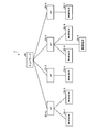
- FIG. 1 is a diagram illustrating a configuration example of a wireless communication system according to the first embodiment.
- FIG. 2 is a diagram illustrating a configuration example of a wireless access point according to the first embodiment.
- FIG. 3 is a diagram illustrating a configuration example of a control station according to the first embodiment.
- FIG. 4 is a diagram for explaining an operation example of the channel assignment device according to the first embodiment.
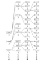
- FIG. 5 is a diagram for explaining an operation example of the channel assignment device according to the first embodiment.
- FIG. 6 is a flowchart for explaining a processing example of the channel assignment device according to the first embodiment.
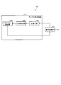
- FIG. 7 is a diagram illustrating a configuration example of a control station according to the second embodiment.
- FIG. 1 is a diagram illustrating a configuration example of a wireless communication system according to the first embodiment.
- FIG. 2 is a diagram illustrating a configuration example of a wireless access point according to the first embodiment.
- FIG. 3 is a diagram illustrating a configuration example of a
- FIG. 8 is a diagram illustrating a configuration example of a wireless communication system according to the third embodiment.
- FIG. 9 is a diagram illustrating a configuration example of a wireless access point according to the third embodiment.
- FIG. 10 is a diagram illustrating a hardware configuration example of the control station.
- FIG. 11 is a diagram illustrating a hardware configuration example of the wireless access point.
- FIG. 1 is a diagram illustrating a configuration example of a wireless communication system according to the first embodiment.
- a wireless communication system 1 includes a control station 10, APs 20-1 to 20-4, and wireless terminals 30-1 to 30-7.
- AP 20-1 to 20-4 may be collectively referred to as AP 20 when not distinguished
- wireless terminals 30-1 to 30-7 may be collectively referred to as wireless terminal 30 when not distinguished.
- the numbers of APs 20 and wireless terminals 30 illustrated in FIG. 1 are examples, and the numbers of APs 20 and wireless terminals 30 included in the wireless communication system 1 are not limited.
- the control station 10 and the AP 20 are connected by a wired link to perform wired communication, and the AP 20 and the wireless terminal 30 are connected by a wireless link to perform wireless communication.
- the AP 20-1 is connected to the wireless terminals 30-1 and 30-2
- the AP 20-2 is connected to the wireless terminal 30-3,
- the AP 20-3 is connected to the wireless terminal 30-4.
- 30-5, and 30-6, and the AP 20-4 is connected to the wireless terminal 30-7.
- the frequency channels that can be used in the wireless communication system 1 are three frequency channels of 1ch, 6ch, and 11ch, and any one of these three frequency channels is assigned to each AP 20 by the control station 10.
- communication between the AP 20-1 and the wireless terminals 30-1 and 30-2 is performed using 1ch
- communication between the AP 20-2 and the wireless terminal 30-3 is performed using 6ch
- communication between the AP 20-3 and the wireless terminals 30-4, 30-5, and 30-6 is performed using 11ch
- communication between the AP 20-4 and the wireless terminal 30-7 is performed using 1ch. .
- the AP 20-1 may be referred to as the first AP, the AP 20-2 as the second AP, the AP 20-3 as the third AP, and the AP 20-4 as the fourth AP.
- FIG. 2 is a diagram illustrating a configuration example of a wireless access point according to the first embodiment.
- the AP 20a illustrated in FIG. 2 corresponds to the AP 20 illustrated in FIG.
- the AP 20a includes an antenna 201, a wireless reception unit 202, a received power measurement unit 203, a measurement result recording unit 204, a wired communication unit 205, a channel setting unit 206, and a wireless transmission unit 207.
- the wireless receiving unit 202 receives a beacon signal transmitted from an AP other than its own AP via the antenna 201.
- the wireless reception unit 202 performs predetermined wireless reception processing such as down-conversion on the received beacon signal, and outputs the beacon signal after the wireless reception processing to the reception power measurement unit 203.
- the wireless reception unit 202 receives beacon signals on all frequency channels of 1ch, 6ch, and 11ch.
- other APs belong to other APs belonging to a radio communication system to which the own AP belongs (hereinafter may be referred to as “own system”), and other radio communication systems (hereinafter referred to as “other systems”). It may be distinguished from other APs that belong to.
- an identifier that can uniquely identify the wireless communication system to which each AP belongs (hereinafter sometimes referred to as “system identifier”) and an identifier that can uniquely identify the AP that is the transmission source of the beacon signal. (Hereinafter may be referred to as “AP identifier”).
- the wireless receiving unit 202 outputs the received beacon signal to the received power measuring unit 203 together with the system identifier and the AP identifier added to the beacon signal.
- the received power measuring unit 203 measures the received power value of each beacon signal at a constant period, and outputs the measurement result to the measurement result recording unit 204.
- the received power measuring unit 203 of the AP 20-1 receives the received power values r 12 , r 13 , r 14 of the beacon signal transmitted from each of the APs 20-2, 20-3, 20-4, and others. measuring an evaluation value r 11 of the received power value of the beacon signal transmitted from the AP that belongs to the system.
- an evaluation value of received power for example, an average value of received power values over all frequency channels that can be used in a wireless communication system can be used.
- r 12 is a received power value at AP 20-1 of a beacon signal transmitted from AP 20-2
- r 13 is a received power value at AP 20-1 of a beacon signal transmitted from AP 20-3
- r 14 is transmitted from AP 20-4.
- the received power value at the AP 20-1 of the received beacon signal is shown. That is, r 12 corresponds to the amount of interference in AP 20-1 from AP 20-2, r 13 corresponds to the amount of interference in AP 20-1 from AP 20-3, and r 14 corresponds to AP 20- from AP 20-4. 1 corresponds to the amount of interference.
- R 11 corresponds to the amount of interference in the AP 20-1 from the AP belonging to another system.
- the received power measuring unit 203 stores a system identifier of its own system in advance. When the system identifier added to the beacon signal matches the system identifier of the own system, the received power measuring unit 203 determines that the beacon signal is transmitted from an AP belonging to the own system. On the other hand, when the system identifier added to the beacon signal does not match the system identifier of the own system, the received power measurement unit 203 determines that the beacon signal is transmitted from an AP belonging to another system. . Also, the received power measuring unit 203 identifies the AP that is the transmission source of the beacon signal based on the AP identifier added to the beacon signal.
- the measurement result recording unit 204 records the received power value and the evaluation value measured by the received power measuring unit 203.
- the measurement result recording unit 204 of the AP 20-1 (FIG. 1) records the received power values r 12 , r 13 , r 14 and the evaluation value r 11 .
- the received power value and the evaluation value recorded in the measurement result recording unit 204 are updated by the received power measuring unit 203 at regular intervals.
- the wired communication unit 205 is connected to the control station 10 via a wired link and communicates with the control station 10.
- the wired communication unit 205 reports the received power value and the evaluation value recorded in the measurement result recording unit 204 to the control station 10 (FIG. 1) at regular intervals.
- the wired communication unit 205 receives the frequency channel assignment result (hereinafter also referred to as “channel assignment result”) notified from the control station 10, and sends the received channel assignment result to the channel setting unit 206. Output.
- the channel setting unit 206 sets the transmission channel in the wireless transmission unit 207 to a frequency channel according to the channel assignment result notified from the control station 10.
- the channel assignment result an AP identifier and a frequency channel number are shown in association with each other. Therefore, the channel setting unit 206 determines that the frequency channel having the channel number associated with the identifier of the own AP in the channel assignment result is the frequency channel assigned to the own AP.
- FIG. 3 is a diagram illustrating a configuration example of a control station according to the first embodiment.
- the control station 10a shown in FIG. 3 corresponds to the control station 10 shown in FIG.
- the control station 10 a includes a wired communication unit 101 and a channel assignment device 11.
- the channel assignment device 11 includes a matrix operation unit 102 and a channel assignment unit 103.
- the wired communication unit 101 is connected to the AP 20a via a wired link and communicates with the AP 20a.
- the wired communication unit 101 receives the received power value and the evaluation value reported from the AP 20a, and outputs the received received power value and evaluation value to the matrix operation unit 102. Further, the wired communication unit 101 notifies the AP 20a of the channel allocation result input from the channel allocation unit 103.
- the wired communication unit 101 notifies the channel assignment result to all APs 20a belonging to the own system all at once. By notifying all APs 20a belonging to the own system all of the channel assignment results, all APs 20a belonging to the own system can simultaneously switch frequency channels.
- the matrix operation unit 102 generates a symmetric matrix having the received power value and the evaluation value reported from the AP 20a as elements (that is, components). Further, the matrix operation unit 102 generates an upper triangular matrix from the generated symmetric matrix. Then, the matrix operation unit 102 outputs the generated upper triangular matrix to the channel assignment unit 103. Details of the operation of the matrix operation unit 102 will be described later.
- the channel allocation unit 103 allocates a frequency channel to the AP 20a using the upper triangular matrix generated by the matrix operation unit 102. Further, the channel assignment unit 103 assigns a frequency channel to the AP 20a, and then outputs a channel assignment result to the wired communication unit 101. Details of the operation of the channel assignment unit 103 will be described later.
- AP20-1 includes a reception power value r 12 in AP20-1 of the transmitted beacon signals from AP20-2, the received power value r 13 in AP20-1 of the transmitted beacon signals from AP20-3, AP 20 a received power value r 14 in AP20-1 of the transmitted beacon signals from -4, and the evaluation value r 11 of the received power value in AP20-1 beacon signal transmitted from the AP that belongs to another system to the control station 10a Report.
- AP20-2 includes a reception power value r 21 in AP20-2 of the transmitted beacon signals from AP20-1, the received power value r 23 in AP20-2 of the transmitted beacon signals from AP20-3, AP 20 -4, the received power value r 24 of the beacon signal transmitted from AP-20-2 and the evaluation value r 22 of the received power value of AP 20-2 of the beacon signal transmitted from the AP belonging to another system to the control station 10a.
- the AP 20-3 receives the received power value r 31 of the beacon signal transmitted from the AP 20-1 at the AP 20-3, the received power value r 32 of the beacon signal transmitted from the AP 20-2, and the AP 20-3.
- the AP 20-4 receives the received power value r 41 of the beacon signal transmitted from the AP 20-1 at the AP 20-4, the received power value r 42 of the beacon signal transmitted from the AP 20-2 at the AP 20-4, and the AP 20 a reception power value r 43 in AP20-4 of the transmitted beacon signals from -3, and the evaluation value r 44 of the received power value in AP20-4 beacon signal transmitted from the AP that belongs to another system to the control station 10a Report.
- the received power values and evaluation values reported from the APs 20-1 to 20-4 correspond to the amount of interference received by each AP from other APs as described above.
- matrix operating section 102 first generates matrix R1 having received power values reported from APs 20-1 to 20-4 as elements, as shown in FIG.
- the matrix R1 is a symmetric matrix. That is, in the matrix R1, r 12 and r 21 are equal, r 13 and r 31 are equal, r 14 and r 41 are equal, r 23 and r 32 are equal, and r 24 and r 42 are equal.
- R 34 and r 43 are equal.
- the matrix operation unit 102 performs the following processing on each element of the symmetric matrix based on the symmetry of the propagation path between the APs.
- the matrix operation unit 102 performs row exchange and column exchange in the matrix R1.
- the exchange of the rows is performed based on the total value (that is, the total value of the amount of interference for each AP 20) S of the elements in each row of the matrix R1.
- the matrix operation unit 102 exchanges the second row and the third row in the matrix R1 so that the total value of the amount of interference increases as the row number increases.
- the matrix operation unit 102 exchanges columns in accordance with the exchange of rows. That is, the matrix operation unit 102 exchanges the second column and the third column after exchanging the second row and the third row in the matrix R1.
- the matrix after the exchange of rows and the exchange of columns is the matrix R2.
- the total value of the amount of interference increases in the order of S 1 in the first row, S 3 in the second row, S 2 in the third row, and S 4 in the fourth row. That is, in the matrix R2, the total value of the amount of interference at each AP 20 increases as the row number increases.
- the matrix R2 is also a symmetric matrix, like the matrix R1.
- the matrix operation unit 102 since the matrix R2 is a symmetric matrix, the matrix operation unit 102 generates an upper triangular matrix R3 by replacing all elements below the diagonal elements of the matrix R2 (that is, lower triangular elements) with 0. The matrix operation unit 102 outputs the generated upper triangular matrix R3 to the channel assignment unit 103.
- the channel allocation unit 103 allocates a frequency channel to each of the APs 20-1 to 20-4 using the upper triangular matrix R3. Allocation of frequency channels is performed according to a predetermined algorithm.
- a predetermined algorithm for example, an algorithm for selecting an optimal allocation candidate corresponding to the amount of interference from a plurality of allocation candidates for frequency channels is used.
- M algorithm is used as a predetermined algorithm is demonstrated, for example.
- frequency channel allocation candidates are selected using the candidate vector c represented by the equation (1).
- Candidate vector c is a vertical vector of N rows and 1 column (N is the total number of APs belonging to the own system), and the i-th element in candidate vector c indicates the channel number of the allocation candidate for i-th AP.
- the candidate vector c, the fourth element c 4 represent the channel number of the allocation candidate for the total value of the interference amount is set for AP20-4 is S 4
- the third element c 3 is the interference level the total value of representing the channel number of the allocation candidate set for AP20-2 is S 2.
- the second element c 2 represent the channel number of the allocation candidate for the total value of the interference amount is set for AP20-3 is S 3
- the first element c 1 is the total value of the interference amount S 1 Represents the channel number of the allocation candidate set for AP 20-1.
- S 1 ⁇ S 3 ⁇ S 2 ⁇ S 4 As described above, “S 1 ⁇ S 3 ⁇ S 2 ⁇ S 4 ”.
- the channel allocation unit 103 first has three candidates of candidate vectors c 1a , c 1b , and c 1c in the first step. Generate a vector. The numbers 1, 6, and 11 in the candidate vectors indicate the channel numbers of 1ch, 6ch, and 11ch. A numerical value of 0 in the candidate vector indicates that the frequency channel assignment candidate is not set.
- the channel allocation unit 103 calculates the metric I k at the k-th step for each of the candidate vectors c 1a , c 1b , and c 1c according to Equation (2).
- the subscript of the candidate vector c and the subscript of the metric I correspond one-to-one.
- channel allocation section 103 generates nine candidate vectors c 2a to c 2i and sets metric I k for each of candidate vectors c 2a to c 2i according to equation (2). calculate.
- the metrics I 2a , I 2e , I 2i are equal to “r 44 + r 33 + r 34 ”
- the metrics I 2b , I 2c , I 2d , I 2f , I 2g , I 2h are “r 44 + r 33 ”.
- the minimum metric in the second step is “r 44 + r 33 ”.
- the channel allocating unit 103 selects four candidate vectors from the candidate vectors c 2b , c 2c , c 2d , c 2f , c 2g , and c 2h according to a predetermined rule or randomly, as shown in FIG. Proceed to the third step.
- channel allocation section 103 generates 12 candidate vectors of candidate vectors c 3a to c 3l , and sets metric I k for each of candidate vectors c 3a to c 3l according to equation (2). calculate.
- the metrics I 3a , I 3e , I 3i , and I 3l are equal to “r 44 + r 33 + r 22 + r 24 ”
- the metrics I 3b , I 3d , I 3g , and I 3k are “r 44 + r 33 + r 22”.
- + R 23 and the metrics I 3c , I 3f , I 3h , and I 3j are equal to“ r 44 + r 33 + r 22 ”.
- channel allocation section 103 selects four candidate vectors of candidate vectors c 3c , c 3f , c 3h , and c 3j from candidate vectors c 3a to c 3l , and proceeds to the fourth step in FIG.
- channel allocation section 103 generates 12 candidate vectors of candidate vectors c 4a to c 4l , and sets metric I k for each of candidate vectors c 4a to c 4l according to equation (2). calculate.
- the metrics I 4a , I 4e , I 4i , and I 4l are equal to “r 44 + r 33 + r 22 + r 11 + r 14 ”, and the metrics I 4b , I 4d , I 4g , and I 4k are “r 44 + r 33”.
- the channel allocating unit 103 selects the smallest metric from “r 44 + r 33 + r 22 + r 11 + r 14 ”, “r 44 + r 33 + r 22 + r 11 + r 13 ”, and “r 44 + r 33 + r 22 + r 11 + r 12 ”. Select. Then, channel assignment section 103 determines a candidate vector having the smallest metric as the frequency channel assignment result.
- any one candidate vector may be selected according to a predetermined rule or randomly. For example, when “r 44 + r 33 + r 22 + r 11 + r 14 ” is the minimum metric, the channel allocation unit 103 determines the candidate vector c 4a as the frequency channel allocation result. When channel allocation section 103 determines candidate vector c 4a as the frequency channel allocation result, channel 1 is allocated to AP 20-4, channel 6 is allocated to AP 20-2, channel 11 is allocated to AP 20-3, and channel 1 is allocated to AP 20-1. .
- the metric calculated in each of the first to fourth steps corresponds to the total interference amount in each AP when the frequency channel indicated by the candidate vector is assigned to each AP. Therefore, selecting a candidate vector having the smallest metric in each of the first to fourth steps is equivalent to selecting a frequency channel allocation candidate that minimizes the total interference amount in each AP. . Further, the throughput of the wireless communication system can be increased as the interference amount at each AP is smaller. Therefore, selecting the frequency channel allocation candidate that minimizes the total amount of interference in each AP can be said to select the optimal frequency channel allocation candidate.
- the number of calculation steps related to frequency channel allocation is on the order of MN.
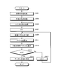
- FIG. 6 is a flowchart for explaining a processing example of the channel assignment device according to the first embodiment.
- the flowchart illustrated in FIG. 6 is started when, for example, the received power value and the evaluation value of each AP 20 of the beacon signal are input from the wired communication unit 101 to the channel assignment device 11.
- step S ⁇ b> 301 the matrix operation unit 102 generates an N-row N-column symmetric matrix R represented by Expression (3).
- N in Equation (3) indicates the total number of APs belonging to the own system.
- step S303 the matrix operation unit 102 performs row exchange and column exchange in the symmetric matrix R represented by Expression (3).
- the matrix operation unit 102 exchanges the rows with each other so that the sum value S i of each row i represented by the equation (4) increases as the row number increases. That is, the matrix operation unit 102 exchanges the rows with each other so that S i is arranged in ascending order from the first row in the symmetric matrix R. Further, after exchanging the rows, the matrix operation unit 102 exchanges each column having the same number as each row that is exchange-symmetric.
- step S305 the matrix operation unit 102 generates an upper triangular matrix by replacing the lower triangular element r ij (i> j) of the symmetric matrix after the exchange of rows and columns with 0.
- step S307 the channel assignment unit 103 sets k to 1.
- step S309 the channel assignment unit 103 generates a candidate vector c.
- step S311 the channel allocation unit 103 calculates a metric I for each candidate vector c using the upper triangular matrix generated in step S305.
- step S313 the channel allocation unit 103 selects M candidate vectors in order from the smallest metric.
- step S315 the channel assignment unit 103 determines whether k is N or not. When k is not N (step S315: No), the process proceeds to step S317, and when k is N (step S315: Yes), the process proceeds to step S319.
- step S317 the channel assignment unit 103 increments k. After incrementing k, the process returns to step S309.
- step S319 the channel allocation unit 103 determines the candidate vector having the minimum metric as the frequency channel allocation result. That is, the channel allocation unit 103 determines frequency channel allocation for each AP. After the process of step S319, the process ends.
- the channel assignment apparatus includes the matrix operation unit 102 and the channel assignment unit 103.
- the matrix operating unit 102 generates an upper triangular matrix from a symmetric matrix whose elements are interference amounts received by APs 20-1 to 20-4 from other APs.
- Channel allocation section 103 allocates a frequency channel to each of APs 20-1 to 20-4 using the upper triangular matrix generated by matrix operation section 102.
- the throughput of the wireless communication system can be improved.
- the matrix operation unit 102 performs row exchange and column exchange in the symmetric matrix based on the magnitude of the amount of interference, and performs an operation above the symmetric matrix after row exchange and column exchange. Generate a triangular matrix.
- the channel allocation unit 103 uses the upper triangular matrix generated by the matrix operation unit 102 to select an optimal allocation candidate according to the amount of interference from a plurality of allocation candidates for frequency channels, according to a predetermined algorithm.
- a frequency channel is allocated to each of APs 20-1 to 20-4.
- frequency channels can be allocated at high speed with a small amount of calculation by minimizing radio wave interference between APs by preferentially allocating frequency channels to APs with a larger amount of interference. it can.
- Example 2 The first embodiment has been described on the assumption that the transmission power values of the APs 20-1 to 20-4 are equal to each other. On the other hand, in the second embodiment, a case where the transmission power values of the APs 20-1 to 20-4 are different from each other will be described.
- FIG. 7 is a diagram illustrating a configuration example of a control station according to the second embodiment.
- the control station 10b illustrated in FIG. 7 corresponds to the control station 10 illustrated in FIG.
- the control station 10 b includes a wired communication unit 101 and a channel assignment device 15.
- the channel assignment device 15 includes a normalization unit 105, a matrix operation unit 102, and a channel assignment unit 103.
- differences from the first embodiment will be described.
- the wired communication unit 101 receives the received power value and the evaluation value reported from the AP 20 a and outputs the received received power value and the evaluation value to the normalization unit 105.
- the normalization unit 105 normalizes the received power value and the evaluation value reported from the AP 20a based on the transmission power value of each AP 20a. For example, the normalization unit 105 normalizes the received power value and the evaluation value r ij reported from the AP 20a according to Expression (5) and Expression (6). In equation (6), pk represents the transmission power value of the kth AP, and p represents the reference transmission power value. Normalization unit 105, by being reported transmit power value p k from k-th AP, knows beforehand. For example, it is preferable to set the average value of the transmission power values of all APs belonging to the own system as the reference transmission power value p. Then, normalization section 105 outputs the received power value and evaluation value r ij ′ after normalization to matrix operation section 102.
- the matrix operation unit 102 generates a symmetric matrix having the normalized received power value and evaluation value r ij ′ as elements instead of the received power value and evaluation value r ij in the first embodiment.
- the subsequent processing in the matrix operation unit 102 and the channel allocation unit 103 is the same as that in the first embodiment.
- the channel assignment apparatus further includes the normalization unit 105.
- Normalization section 105 normalizes the amount of interference received by each AP 20-1 to 20-4 from another AP based on the transmission power value of the other AP.
- the matrix operation unit 102 generates an upper triangular matrix from a symmetric matrix having the normalized interference amount as an element.
- Example 3 In the first embodiment, the case where the channel assignment apparatus is mounted on the control station 10 has been described. On the other hand, in the third embodiment, a case where the channel allocation device is mounted on a representative AP among a plurality of APs 20 will be described.
- FIG. 8 is a diagram illustrating a configuration example of a wireless communication system according to the third embodiment.
- the wireless communication system 2 includes a network 40, APs 20-1 to 20-4, and wireless terminals 30-1 to 30-7.
- the APs 20-1 to 20-4 are connected to each other via the network 40 and can communicate with each other.
- AP 20-1 among APs 20-1 to 20-4 is a representative AP in which a channel allocation device is mounted.
- FIG. 9 is a diagram illustrating a configuration example of a wireless access point according to the third embodiment.
- the AP 20b shown in FIG. 9 corresponds to the representative AP 20-1 shown in FIG.
- the configuration example of the APs 20-2 to 20-4 other than the representative AP 20-1 is the same as that of FIG. 2, and the wired communication unit 205 of the APs 20-2 to 20-4 is wired via the network 40 with the representative AP 20-1. It is connected by a link and communicates with the representative AP 20-1.
- the wired communication unit 205 reports the received power value and the evaluation value recorded in the measurement result recording unit 204 to the representative AP 20-1 at regular intervals.
- the wired communication unit 205 receives the channel assignment result notified from the representative AP 20-1 and outputs the received channel assignment result to the channel setting unit 206.
- the AP 20b includes an antenna 201, a wireless reception unit 202, a received power measurement unit 203, a measurement result recording unit 204, a wired communication unit 211, a channel setting unit 215, a wireless transmission unit 207, a channel And an allocating device 21.
- the channel assignment device 21 includes a matrix operation unit 212 and a channel assignment unit 213.
- the matrix operation unit 212 receives the received power values and evaluation values r 21 , r 22 , r 23 , r 24 , r 31 , r 32 , r 33 , r 34 , r 41 , reported from the APs 20-2 to 20-4.
- a symmetric matrix is generated that includes r 42 , r 43 , r 44 and the received power values and evaluation values r 11 , r 12 , r 13 , r 14 recorded in the measurement result recording unit 204.
- the matrix operation unit 212 generates an upper triangular matrix from the generated symmetric matrix. Then, the matrix operation unit 212 outputs the generated upper triangular matrix to the channel allocation unit 213.
- the operation of the matrix operation unit 212 is the same as the operation of the matrix operation unit 102 (FIG. 3) of the first embodiment.
- the operation of the channel assignment unit 213 is the same as the operation of the channel assignment unit 103 (FIG. 3) of the first embodiment. However, the channel allocation unit 213 outputs the channel allocation result to the wired communication unit 211 and the channel setting unit 215.
- the channel setting unit 215 sets the transmission channel in the wireless transmission unit 207 to a frequency channel according to the channel allocation result input from the channel allocation unit 213.
- the AP has a channel allocation device.
- an average value of reception power values over all frequency channels usable in the wireless communication system is obtained.
- an expected value in the time direction of the received power value of a beacon signal transmitted from an AP belonging to another system may be used as the evaluation value. That is, in each AP, when the time during which a beacon signal transmitted from an AP belonging to another system is received during a predetermined measurement period T seconds is defined as t seconds, the reception time rate is defined as t / T.
- the reception power value of a beacon signal transmitted from an AP belonging to another system may be weighted by the reception time rate t / T, and the weighted reception power value may be used as an evaluation value.
- the amount of interference at each AP was measured based on the received power value at each AP.
- the amount of interference at each AP is measured based on the received power value at each AP, the number of wireless terminals connected to each AP, and the uplink or downlink traffic volume at each AP. Also good.
- the amount of interference at each AP may be measured based on the received power value at each AP and the transmission power value at each AP.
- the amount of interference from APs belonging to other systems may be measured for each frequency channel that can be used in the own system.
- frequency channels are allocated using an upper triangular matrix generated from a symmetric matrix.
- a lower triangular matrix may be generated from a symmetric matrix, and frequency channels may be allocated using the lower triangular matrix.
- the following points are different from assigning frequency channels using an upper triangular matrix.
- the rows are exchanged so that the total value of the amount of interference decreases as the row number increases.
- a lower upper triangular matrix is generated by replacing all elements above diagonal elements (that is, upper triangular elements) with 0 in the symmetric matrix after exchanging rows and columns.
- the metric I k at the k-th step is calculated according to the equation (7).
- frequency channels are allocated by taking 1ch, 6ch, and 11ch as examples of combinations of frequency channel allocation candidates.
- frequency channel allocation may be performed using other allocation candidate combinations such as 2ch, 7ch, and 12ch combinations and 1ch, 5ch, 9ch, and 13ch combinations as combinations of frequency channel allocation candidates. good.
- the allocation result having a smaller metric may be adopted by comparing the metric in the k-th step of the result of frequency channel allocation using a combination of 7ch and 12ch).
- each AP when assigning a frequency channel to each of a plurality of APs, each AP is generated from a symmetric matrix whose element is the amount of interference received from other APs, and the symmetric matrix. An upper or lower triangular matrix was used.
- each of a plurality of APs processes a “numerical value group” having the amount of interference received from another AP as an element, based on the symmetry of the propagation path, and replaces the upper triangular matrix and the lower triangular matrix with processing.
- a frequency channel may be assigned to each of a plurality of APs using a later numerical group.
- the symmetric matrix is an example of a numerical group whose elements are interference amounts received from other APs by each of the plurality of APs.
- the upper triangular matrix and the lower triangular matrix are processed after processing based on the symmetry of the propagation path. It is an example of a numerical value group.
- the matrix operation units 102 and 212 are examples of an “interference amount processing unit” that processes a numerical value group having an interference amount received by another AP as an element based on the symmetry of the propagation path. It is. That is, the numerical value group having the amount of interference as an element is not necessarily expressed by a matrix, and a process equivalent to an operation on the matrix may be directly performed on the numerical value group.
- the symmetric matrix uses the amount of interference received by each AP from another AP as an element.
- the symmetric matrix may include the amount of interference received by each AP from another AP and the amount of interference received by each AP from an interference source other than the other AP.
- interference sources other than APs include radio wave transmission sources that transmit radio waves at a frequency included in a frequency band used in the own system, such as a wireless terminal and a microwave oven.
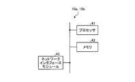
- FIG. 10 is a diagram illustrating a hardware configuration example of the control station.
- the control stations 10 a and 10 b include a processor 41, a memory 42, and a network interface module 43 as hardware components.
- the processor 41 include a CPU (Central Processing Unit), a DSP (Digital Signal Processor), and an FPGA (Field Programmable Gate Array).
- the control stations 10a and 10b may have an LSI (Large Scale Integrated circuit) including a processor 41 and peripheral circuits.
- the memory 42 include a RAM such as SDRAM, a ROM, a flash memory, and the like.
- the matrix operation unit 102, the channel assignment unit 103, and the normalization unit 105 are realized by the processor 41.
- the wired communication unit 101 is realized by the network interface module 43.
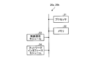
- FIG. 11 is a diagram illustrating a hardware configuration example of the wireless access point.
- the APs 20 a and 20 b include a processor 51, a memory 52, a wireless communication module 53, and a network interface module 54 as hardware components.
- the processor 51 include a CPU, a DSP, an FPGA, and the like.
- the APs 20a and 20b may include an LSI including the processor 51 and peripheral circuits.
- the memory 52 include a RAM such as an SDRAM, a ROM, a flash memory, and the like.
- the received power measurement unit 203, the channel setting units 206 and 215, the matrix operation unit 212, and the channel allocation unit 213 are realized by the processor 51.
- the measurement result recording unit 204 is realized by the memory 52.
- the antenna 201, the wireless reception unit 202, and the wireless transmission unit 207 are realized by the wireless communication module 53.
- the wired communication units 205 and 211 are realized by the network interface module 54.
Landscapes
- Engineering & Computer Science (AREA)
- Computer Networks & Wireless Communication (AREA)
- Signal Processing (AREA)
- Physics & Mathematics (AREA)
- Mathematical Physics (AREA)
- Power Engineering (AREA)
- Quality & Reliability (AREA)
- Mobile Radio Communication Systems (AREA)
Abstract
無線通信システムのスループットを向上することができるチャネル割当装置。このチャネル割当装置(11)は、行列操作部(102)と、チャネル割当部(103)とを有する。行列操作部(102)は、複数のAPの各々での被干渉量を要素とする対称行列から上三角行列または下三角行列を生成する。チャネル割当部(103)は、行列操作部(102)によって生成された上三角行列または下三角行列を用いて、複数のAPの各々に周波数チャネルを割り当てる。
Description
本発明は、チャネル割当装置、無線通信システム及びチャネル割当方法に関する。
無線LAN(Wireless Local Area Network)等の無線通信システムでは、無線アクセスポイントと無線端末との間で周波数チャネルを用いて無線通信が行われる。各無線アクセスポイントには、無線通信システム内で使用可能な複数の周波数チャネルのうち何れか一つの周波数チャネルが割り当てられる。以下では、無線アクセスポイントを「AP」と表記することがある。
無線通信システムにおいて使用可能な周波数チャネルの数には限りがあるため、使用可能な周波数チャネルの数より多い数のAPが無線通信システム内に存在する場合、同一の周波数チャネルが複数のAPに割り当てられることがある。同一の周波数チャネルが複数のAPに割り当てられると、それらの複数のAP間で電波干渉が発生して、無線通信システムのスループットが低下する。また、AP間での電波干渉は無線環境の変化に応じて増減する。そこで、AP間での電波干渉を低減するために、APに対する周波数チャネルの割当を無線環境の変化に応じて動的に行う「ダイナミック割当法」がある。また、ダイナミック割当法の関連技術として、例えば、無線通信システム内の全APに対する周波数チャネルの割当を一斉に行うものがある。
上記の関連技術では、無線環境の変化に応じて、全APの周波数チャネルを一斉に変更することができる。しかし、上記の関連技術では、周波数チャネルの割当に係る計算の量(以下では「割当計算量」と呼ぶことがある)が、無線通信システム内に存在するAPの数に応じて指数関数的に増大する。例えば、無線通信システム内にN個のAPが設置された環境においてC個の周波数チャネルが使用可能である場合、周波数チャネルの割当に係る計算パターン数はCNとなる。このように割当計算量が指数関数的に増大すると、周波数チャネルの割当に係る計算時間(以下では「割当計算時間」と呼ぶことがある)が長くなってしまう。割当計算時間が長くなると、周波数チャネルの割当の基になる無線環境の測定時点から、周波数チャネルの割当時点までの間に長時間経過してしまうため、周波数チャネルの割当時点での実際の無線環境が、測定時点での無線環境と大きく異なることがある。このように、周波数チャネルの割当時点での実際の無線環境が測定時点での無線環境と大きく異なると、実際の無線環境に応じた周波数チャネルの最適な割当が為されないため、無線通信システムのスループットが低下する。つまり、無線環境に基づく周波数チャネルの割当において割当計算量が増大すると、無線通信システムのスループットが低下することがある。
開示の技術は、上記に鑑みてなされたものであって、無線通信システムのスループットを向上することを目的とする。
開示の態様では、チャネル割当装置は、被干渉量処理部と、割当部とを有する。前記被干渉量処理部は、複数の無線アクセスポイントの各々での被干渉量を要素とする数値群を、伝搬路の対称性に基づいて処理する。前記割当部は、前記被干渉量処理部での処理後の数値群を用いて、前記複数の無線アクセスポイントの各々に周波数チャネルを割り当てる。
開示の態様によれば、無線通信システムのスループットを向上できる。
以下に、本願の開示するチャネル割当装置、無線通信システム及びチャネル割当方法の実施例を図面に基づいて説明する。なお、この実施例により本願の開示するチャネル割当装置、無線通信システム及びチャネル割当方法が限定されるものではない。また、各実施例において同一の機能を有する構成、及び、同一の処理を行うステップには同一の符号を付し、重複する説明を省略する。
[実施例1]
<無線通信システムの構成例>
図1は、実施例1の無線通信システムの構成例を示す図である。図1において、無線通信システム1は、制御局10と、AP20-1~20-4と、無線端末30-1~30-7とを有する。以下では、AP20-1~20-4を区別しない場合にはAP20と総称し、無線端末30-1~30-7を区別しない場合には無線端末30と総称することがある。また、図1に示すAP20及び無線端末30の台数は一例であり、無線通信システム1が有するAP20及び無線端末30の台数は限定されない。
<無線通信システムの構成例>
図1は、実施例1の無線通信システムの構成例を示す図である。図1において、無線通信システム1は、制御局10と、AP20-1~20-4と、無線端末30-1~30-7とを有する。以下では、AP20-1~20-4を区別しない場合にはAP20と総称し、無線端末30-1~30-7を区別しない場合には無線端末30と総称することがある。また、図1に示すAP20及び無線端末30の台数は一例であり、無線通信システム1が有するAP20及び無線端末30の台数は限定されない。
制御局10とAP20とは有線リンクで接続されて有線通信を行い、AP20と無線端末30とは無線リンクで接続されて無線通信を行う。図1に示す例では、AP20-1は無線端末30-1,30-2と接続されており、AP20-2は無線端末30-3と接続されており、AP20-3は無線端末30-4,30-5,30-6と接続されており、AP20-4は無線端末30-7と接続されている。また例えば、無線通信システム1において使用可能な周波数チャネルは、1ch,6ch,11chの3つの周波数チャネルであり、これらの3つの周波数チャネルの何れかが、制御局10によって各AP20に割り当てられる。よって例えば、AP20-1と無線端末30-1,30-2との通信は1chを用いて行われ、AP20-2と無線端末30-3との通信は6chを用いて行われる。また例えば、AP20-3と無線端末30-4,30-5,30-6との通信は11chを用いて行われ、AP20-4と無線端末30-7との通信は1chを用いて行われる。
以下では、無線通信システム1において使用可能な周波数チャネルが、1ch,6ch,11chの3つの周波数チャネルである場合を一例に挙げて説明する。また以下では、AP20-1は1番AP、AP20-2は2番AP、AP20-3は3番AP、AP20-4は4番APと呼ばれることがある。
<無線アクセスポイントの構成例>
図2は、実施例1の無線アクセスポイントの構成例を示す図である。図2に示すAP20aは、図1に示すAP20に相当する。図2において、AP20aは、アンテナ201と、無線受信部202と、受信電力測定部203と、測定結果記録部204と、有線通信部205と、チャネル設定部206と、無線送信部207とを有する。
図2は、実施例1の無線アクセスポイントの構成例を示す図である。図2に示すAP20aは、図1に示すAP20に相当する。図2において、AP20aは、アンテナ201と、無線受信部202と、受信電力測定部203と、測定結果記録部204と、有線通信部205と、チャネル設定部206と、無線送信部207とを有する。
無線受信部202は、自AP以外の他のAPから送信されたビーコン信号をアンテナ201を介して受信する。無線受信部202は、受信したビーコン信号にダウンコンバート等の所定の無線受信処理を施し、無線受信処理後のビーコン信号を受信電力測定部203へ出力する。無線受信部202は、1ch,6ch,11chのすべての周波数チャネルでビーコン信号を受信する。ここで、他のAPは、自APが属する無線通信システム(以下では「自システム」と呼ぶことがある)に属する他のAPと、自システム以外の無線通信システム(以下では「他システム」と呼ぶことがある)に属する他のAPとに区別される。そこで、ビーコン信号には、各APが属する無線通信システムを一意に特定可能な識別子(以下では「システム識別子」と呼ぶことがある)と、ビーコン信号の送信元のAPを一意に特定可能な識別子(以下では「AP識別子」と呼ぶことがある)とが付加されている。無線受信部202は、受信したビーコン信号を、当該ビーコン信号に付加されているシステム識別子及びAP識別子と共に受信電力測定部203へ出力する。
受信電力測定部203は、一定周期で、各ビーコン信号の受信電力値を測定し、測定結果を測定結果記録部204へ出力する。例えばAP20-1(図1)の受信電力測定部203は、AP20-2,20-3,20-4の各々から送信されたビーコン信号の受信電力値r12,r13,r14と、他システムに属するAPから送信されたビーコン信号の受信電力値の評価値r11とを測定する。受信電力の評価値として、例えば、無線通信システムにおいて使用可能なすべての周波数チャネルに渡る受信電力値の平均値を用いることができる。r12はAP20-2から送信されたビーコン信号のAP20-1における受信電力値、r13はAP20-3から送信されたビーコン信号のAP20-1における受信電力値、r14はAP20-4から送信されたビーコン信号のAP20-1における受信電力値を示す。つまり、r12はAP20-2からのAP20-1における被干渉量に相当し、r13はAP20-3からのAP20-1における被干渉量に相当し、r14はAP20-4からのAP20-1における被干渉量に相当する。また、r11は他システムに属するAPからのAP20-1における被干渉量に相当する。
また、受信電力測定部203は、自システムのシステム識別子を予め記憶している。受信電力測定部203は、ビーコン信号に付加されているシステム識別子が自システムのシステム識別子と一致するときは、当該ビーコン信号が自システムに属するAPから送信されたものであると判断する。一方で、受信電力測定部203は、ビーコン信号に付加されているシステム識別子が自システムのシステム識別子と一致しないときは、当該ビーコン信号が他システムに属するAPから送信されたものであると判断する。また、受信電力測定部203は、ビーコン信号に付加されているAP識別子に基づいて、当該ビーコン信号の送信元のAPを特定する。
測定結果記録部204は、受信電力測定部203によって測定された受信電力値及び評価値を記録する。例えばAP20-1(図1)の測定結果記録部204は、受信電力値r12,r13,r14及び評価値r11を記録する。測定結果記録部204に記録される受信電力値及び評価値は受信電力測定部203によって一定周期で更新される。
有線通信部205は、制御局10と有線リンクで接続されて制御局10と通信する。有線通信部205は、測定結果記録部204に記録された受信電力値及び評価値を制御局10(図1)へ一定周期で報告する。また、有線通信部205は、制御局10から通知された、周波数チャネルの割当結果(以下では「チャネル割当結果」と呼ぶことがある)を受信し、受信したチャネル割当結果をチャネル設定部206へ出力する。
チャネル設定部206は、無線送信部207における送信チャネルを、制御局10から通知されたチャネル割当結果に従った周波数チャネルに設定する。チャネル割当結果には、AP識別子と、周波数チャネル番号とが対応付けて示されている。そこで、チャネル設定部206は、チャネル割当結果において自APの識別子に対応付けられているチャネル番号の周波数チャネルが、自APに割り当てられた周波数チャネルであると判断する。
無線送信部207は、チャネル設定部206から設定される送信チャネルに従って、ベースバンド信号及びビーコン信号にアップコンバート等の所定の無線送信処理を施し、無線送信処理後の信号をアンテナ201を介して送信する。ベースバンド信号及びビーコン信号には、自システムのシステム識別子及び自APのAP識別子が付加されている。
<制御局の構成例>
図3は、実施例1の制御局の構成例を示す図である。図3に示す制御局10aは、図1に示す制御局10に相当する。図3において、制御局10aは、有線通信部101と、チャネル割当装置11とを有する。チャネル割当装置11は、行列操作部102と、チャネル割当部103とを有する。
図3は、実施例1の制御局の構成例を示す図である。図3に示す制御局10aは、図1に示す制御局10に相当する。図3において、制御局10aは、有線通信部101と、チャネル割当装置11とを有する。チャネル割当装置11は、行列操作部102と、チャネル割当部103とを有する。
有線通信部101は、AP20aと有線リンクで接続されてAP20aと通信する。有線通信部101は、AP20aから報告された受信電力値及び評価値を受信し、受信した受信電力値及び評価置を行列操作部102へ出力する。また、有線通信部101は、チャネル割当部103から入力されるチャネル割当結果をAP20aへ通知する。有線通信部101は、チャネル割当結果を自システムに属する全AP20aへ一斉に通知する。チャネル割当結果が自システムに属する全AP20aへ一斉に通知されることにより、自システムに属する全AP20aは周波数チャネルを一斉に切り替えることができる。
行列操作部102は、AP20aから報告された受信電力値及び評価値を要素(つまり、成分)とする対称行列を生成する。また、行列操作部102は、生成した対称行列から上三角行列を生成する。そして、行列操作部102は、生成した上三角行列をチャネル割当部103へ出力する。行列操作部102の動作の詳細は後述する。
チャネル割当部103は、行列操作部102によって生成された上三角行列を用いてAP20aに周波数チャネルを割り当てる。また、チャネル割当部103は、AP20aに周波数チャネルを割り当てた後、チャネル割当結果を有線通信部101へ出力する。チャネル割当部103の動作の詳細は後述する。
<チャネル割当装置の動作例>
図4及び図5は、実施例1のチャネル割当装置の動作例の説明に供する図である。以下の説明では、図1に示すAP20-1~20-4の各々が、図2に示すAP20aに相当する。よって、AP20-1は、AP20-2から送信されたビーコン信号のAP20-1における受信電力値r12と、AP20-3から送信されたビーコン信号のAP20-1における受信電力値r13と、AP20-4から送信されたビーコン信号のAP20-1における受信電力値r14と、他システムに属するAPから送信されたビーコン信号のAP20-1における受信電力値の評価値r11とを制御局10aへ報告する。また、AP20-2は、AP20-1から送信されたビーコン信号のAP20-2における受信電力値r21と、AP20-3から送信されたビーコン信号のAP20-2における受信電力値r23と、AP20-4から送信されたビーコン信号のAP20-2における受信電力値r24と、他システムに属するAPから送信されたビーコン信号のAP20-2における受信電力値の評価値r22とを制御局10aへ報告する。また、AP20-3は、AP20-1から送信されたビーコン信号のAP20-3における受信電力値r31と、AP20-2から送信されたビーコン信号のAP20-3における受信電力値r32と、AP20-4から送信されたビーコン信号のAP20-3における受信電力値r34と、他システムに属するAPから送信されたビーコン信号のAP20-3における受信電力値の評価値r33とを制御局10aへ報告する。また、AP20-4は、AP20-1から送信されたビーコン信号のAP20-4における受信電力値r41と、AP20-2から送信されたビーコン信号のAP20-4における受信電力値r42と、AP20-3から送信されたビーコン信号のAP20-4における受信電力値r43と、他システムに属するAPから送信されたビーコン信号のAP20-4における受信電力値の評価値r44とを制御局10aへ報告する。AP20-1~20-4から報告される受信電力値及び評価値は、上記のとおり、各APが他のAPから受ける被干渉量に相当する。
図4及び図5は、実施例1のチャネル割当装置の動作例の説明に供する図である。以下の説明では、図1に示すAP20-1~20-4の各々が、図2に示すAP20aに相当する。よって、AP20-1は、AP20-2から送信されたビーコン信号のAP20-1における受信電力値r12と、AP20-3から送信されたビーコン信号のAP20-1における受信電力値r13と、AP20-4から送信されたビーコン信号のAP20-1における受信電力値r14と、他システムに属するAPから送信されたビーコン信号のAP20-1における受信電力値の評価値r11とを制御局10aへ報告する。また、AP20-2は、AP20-1から送信されたビーコン信号のAP20-2における受信電力値r21と、AP20-3から送信されたビーコン信号のAP20-2における受信電力値r23と、AP20-4から送信されたビーコン信号のAP20-2における受信電力値r24と、他システムに属するAPから送信されたビーコン信号のAP20-2における受信電力値の評価値r22とを制御局10aへ報告する。また、AP20-3は、AP20-1から送信されたビーコン信号のAP20-3における受信電力値r31と、AP20-2から送信されたビーコン信号のAP20-3における受信電力値r32と、AP20-4から送信されたビーコン信号のAP20-3における受信電力値r34と、他システムに属するAPから送信されたビーコン信号のAP20-3における受信電力値の評価値r33とを制御局10aへ報告する。また、AP20-4は、AP20-1から送信されたビーコン信号のAP20-4における受信電力値r41と、AP20-2から送信されたビーコン信号のAP20-4における受信電力値r42と、AP20-3から送信されたビーコン信号のAP20-4における受信電力値r43と、他システムに属するAPから送信されたビーコン信号のAP20-4における受信電力値の評価値r44とを制御局10aへ報告する。AP20-1~20-4から報告される受信電力値及び評価値は、上記のとおり、各APが他のAPから受ける被干渉量に相当する。
チャネル割当装置11(図3)において、行列操作部102は、図4に示すように、まず、AP20-1~20-4から報告された受信電力値を要素とする行列R1を生成する。ここで、AP20-1~20-4の送信電力値は互いに等しく、かつ、AP20-1~20-4において各AP間の伝送路が対称であるとする。よって、行列R1は対称行列となる。つまり、行列R1において、r12とr21とは等しく、r13とr31とは等しく、r14とr41とは等しく、r23とr32とは等しく、r24とr42とは等しく、r34とr43とは等しい。行列操作部102は、このような各AP間での伝搬路の対称性に基づいて、対称行列の各要素に対して、以下に示すような処理を施す。
すなわち、行列操作部102は、行列R1において、行の交換と列の交換とを行う。行の交換は、行列R1の各行の要素の合計値(つまり、AP20毎の被干渉量の合計値)Sに基づいて行われる。ここでは、AP20-1の被干渉量の合計値はS1=r11+r12+r13+r14となり、AP20-2の被干渉量の合計値はS2=r21+r22+r23+r24となる。また、AP20-3の被干渉量の合計値はS3=r31+r32+r33+r34となり、AP20-4の被干渉量の合計値はS4=r41+r42+r43+r44となる。ここで、例えば、「S1<S3<S2<S4」であるとする。そこで、行列操作部102は、行番号が大きくなるに従って被干渉量の合計値が大きくなるように、行列R1において、2行目と3行目とを交換する。次いで、行列操作部102は、行の交換に合わせて、列を交換する。つまり、行列操作部102は、行列R1において、2行目と3行目との交換後、2列目と3列目とを交換する。
よって、行の交換と列の交換とが為された後の行列は、行列R2となる。行列R2では、被干渉量の合計値は、1行目におけるS1、2行目におけるS3、3行目におけるS2、4行目におけるS4の順に大きくなっている。つまり、行列R2では、行番号が大きくなるに従って、各AP20での被干渉量の合計値が大きくなっている。また、行の交換に合わせて列の交換を行ったことにより、行列R2によって表現される物理的な状況は、行列R1によって表現される物理的な状況と等価になる。よって、行列R2も、行列R1と同様に、対称行列となる。
次いで、行列操作部102は、行列R2が対称行列であるため、行列R2の対角要素より下の要素(つまり、下三角要素)のすべてを0に置き換えることによって上三角行列R3を生成する。行列操作部102は、生成した上三角行列R3をチャネル割当部103へ出力する。
チャネル割当部103は、上三角行列R3を用いて、AP20-1~20-4の各々に周波数チャネルを割り当てる。周波数チャネルの割当は、所定のアルゴリズムに従って行われる。所定のアルゴリズムとして、例えば、周波数チャネルの複数の割当候補から被干渉量の大きさに応じた最適な割当候補を選択するアルゴリズムを用いる。以下では、所定のアルゴリズムとして、例えば、Mアルゴリズムを用いる場合について説明する。また、以下では、各ステップにおける選択候補数Mを、例えばM=4とする。また、以下では、式(1)によって表される候補ベクトルcを用いて周波数チャネルの割当候補を選択する。候補ベクトルcは、N行1列の縦ベクトルであり(Nは、自システムに属するAPの総数)、候補ベクトルcにおけるi番要素は、i番APに対する割当候補のチャネル番号を示す。
よって例えば、候補ベクトルcにおいて、第4要素c4は被干渉量の合計値がS4であるAP20-4に対して設定した割当候補のチャネル番号を表し、第3要素c3は被干渉量の合計値がS2であるAP20-2に対して設定した割当候補のチャネル番号を表す。また、第2要素c2は被干渉量の合計値がS3であるAP20-3に対して設定した割当候補のチャネル番号を表し、第1要素c1は被干渉量の合計値がS1であるAP20-1に対して設定した割当候補のチャネル番号を表す。なお、上記のとおり「S1<S3<S2<S4」である。

図5に示すように、チャネル割当部103は、k=1~4の4回のステップそれぞれにおいて、AP1台ずつ、周波数チャネルの割当候補を追加していく。また、チャネル割当部103は、被干渉量の合計値がより大きいAPから順に、周波数チャネルの割当候補を設定していく。
すなわち、自システムにおいて使用可能な周波数チャネルは1ch,6ch,11chの3つのチャネルであるため、チャネル割当部103は、まず第1ステップで、候補ベクトルc1a,c1b,c1cの3つの候補ベクトルを生成する。候補ベクトルにおける1,6,11の数値は、1ch,6ch,11chのチャネル番号を示す。また、候補ベクトルにおける0の数値は、周波数チャネルの割当候補の設定前であることを示す。チャネル割当部103は、候補ベクトルc1a,c1b,c1cの各々について、第kステップにおけるメトリックIkを式(2)に従って算出する。

よって、図5における第1ステップでは、c1aについてのメトリックI1a、c1bについてのメトリックI1b、c1cについてのメトリックI1cはすべてr44で等しくなる。また、M=4である。このため、チャネル割当部103は、c1a、c1b及びc1cの3個の候補ベクトルすべてを選択して、図5における第2ステップへ進む。以下、候補ベクトルcの添え字と、メトリックIの添え字とは1対1で対応する。
次いで、第2ステップでは、チャネル割当部103は、候補ベクトルc2a~c2iの9個の候補ベクトルを生成し、候補ベクトルc2a~c2iの各々について、メトリックIkを式(2)に従って算出する。その結果、メトリックI2a,I2e,I2iは「r44+r33+r34」で等しくなり、メトリックI2b,I2c,I2d,I2f,I2g,I2hは「r44+r33」で等しくなる。よって、第2ステップにおける最小のメトリックは「r44+r33」となる。また、M=4である。そこで、チャネル割当部103は、候補ベクトルc2b,c2c,c2d,c2f,c2g,c2hから4個の候補ベクトルを、所定の規則に従って、または、ランダムに選択して、図5における第3ステップへ進む。ここでは、候補ベクトルc2b,c2d,c2g,c2hの4個の候補ベクトルが選択されたものとする。
次いで、第3ステップでは、チャネル割当部103は、候補ベクトルc3a~c3lの12個の候補ベクトルを生成し、候補ベクトルc3a~c3lの各々について、メトリックIkを式(2)に従って算出する。その結果、メトリックI3a,I3e,I3i,I3lは「r44+r33+r22+r24」で等しくなり、メトリックI3b,I3d,I3g,I3kは「r44+r33+r22+r23」で等しくなり、メトリックI3c,I3f,I3h,I3jは「r44+r33+r22」で等しくなる。よって、第3ステップにおける最小のメトリックは「r44+r33+r22」となる。また、M=4である。そこで、チャネル割当部103は、候補ベクトルc3a~c3lから候補ベクトルc3c,c3f,c3h,c3jの4個の候補ベクトルを選択して、図5における第4ステップへ進む。
次いで、第4ステップでは、チャネル割当部103は、候補ベクトルc4a~c4lの12個の候補ベクトルを生成し、候補ベクトルc4a~c4lの各々について、メトリックIkを式(2)に従って算出する。その結果、メトリックI4a,I4e,I4i,I4lは「r44+r33+r22+r11+r14」で等しくなり、メトリックI4b,I4d,I4g,I4kは「r44+r33+r22+r11+r13」で等しくなり、メトリックI4c,I4f,I4h,I4jは「r44+r33+r22+r11+r12」で等しくなる。チャネル割当部103は、「r44+r33+r22+r11+r14」、「r44+r33+r22+r11+r13」、「r44+r33+r22+r11+r12」のうちから最小のメトリックを選択する。そして、チャネル割当部103は、最小のメトリックを有する候補ベクトルを周波数チャネルの割当結果に決定する。最小のメトリックを有する候補ベクトルが複数存在する場合は、所定の規則に従って、または、ランダムに何れか一つの候補ベクトルを選択すると良い。例えば、「r44+r33+r22+r11+r14」が最小のメトリックとなる場合、チャネル割当部103は、候補ベクトルc4aを周波数チャネルの割当結果に決定する。チャネル割当部103は、候補ベクトルc4aを周波数チャネルの割当結果に決定した場合、1chをAP20-4に、6chをAP20-2に、11chをAP20-3に、1chをAP20-1にそれぞれ割り当てる。
ここで、第1~第4ステップの各ステップで算出されるメトリックは、候補ベクトルで示される周波数チャネルが各APに割り当てられた場合の各APにおける被干渉量の合計値に相当する。よって、第1~第4ステップの各ステップにおいてメトリックが最小の候補ベクトルを選択することは、各APにおける被干渉量の合計値を最小とする周波数チャネルの割当候補を選択していることに等しい。また、各APにおける被干渉量が小さいほど無線通信システムのスループットを大きくすることができる。よって、各APにおける被干渉量の合計値を最小とする周波数チャネルの割当候補を選択することは、周波数チャネルの最適な割当候補を選択していると言える。
また、各ステップにおける選択候補数をM、ステップ総数をN(Nは、自システムに属するAPの総数)とすると、周波数チャネルの割当に係る計算工数はMN程度のオーダになる。また、各ステップにおける選択候補数Mは、M=CNとするのが好ましい(Cは、自システムにおいて使用可能な周波数チャネル数)。よって、上記動作例によれば、周波数チャネルの割当に係る計算工数をN2程度のオーダに抑えることができる。
<チャネル割当装置の処理例>
図6は、実施例1のチャネル割当装置の処理例の説明に供するフローチャートである。図6に示すフローチャートは、例えば、ビーコン信号の各AP20における受信電力値及び評価値が有線通信部101からチャネル割当装置11へ入力されたときに開始される。
図6は、実施例1のチャネル割当装置の処理例の説明に供するフローチャートである。図6に示すフローチャートは、例えば、ビーコン信号の各AP20における受信電力値及び評価値が有線通信部101からチャネル割当装置11へ入力されたときに開始される。
図6において、ステップS301では、行列操作部102は、式(3)によって表されるN行N列の対称行列Rを生成する。式(3)におけるNは、自システムに属するAPの総数を示す。

次いで、ステップS303では、行列操作部102は、式(3)によって表される対称行列Rにおいて、行の交換及び列の交換を行う。行列操作部102は、式(4)によって表される各行iの和の値Siが、行番号が大きくなるに従って大きくなるように、各行を相互に交換する。つまり、行列操作部102は、対称行列Rにおいて、Siが1行目から昇順に並ぶように各行を相互に交換する。また、行列操作部102は、行の交換後、交換対称とした各行と同一番号の各列を交換する。

次いで、ステップS305では、行列操作部102は、行及び列の交換後の対称行列の下三角要素rij(i>j)を0に置き換えることにより上三角行列を生成する。
次いで、ステップS307では、チャネル割当部103は、kを1に設定する。
次いで、ステップS309では、チャネル割当部103は、候補ベクトルcを生成する。
次いで、ステップS311では、チャネル割当部103は、ステップS305で生成した上三角行列を用いて、各候補ベクトルcについてメトリックIを算出する。
次いで、ステップS313では、チャネル割当部103は、メトリックが小さいものから順にM個の候補ベクトルを選択する。
次いで、ステップS315では、チャネル割当部103は、kがNであるか否かを判断する。kがNでないときは(ステップS315:No)、処理はステップS317へ進み、kがNであるときは(ステップS315:Yes)、処理はステップS319へ進む。
ステップS317では、チャネル割当部103は、kをインクリメントする。kのインクリメント後、処理はステップS309へ戻る。
ステップS319では、チャネル割当部103は、最小のメトリックを有する候補ベクトルを周波数チャネルの割当結果に決定する。つまり、チャネル割当部103は、各APに対する周波数チャネルの割当を決定する。ステップS319の処理後、処理は終了する。
以上のように、実施例1のチャネル割当装置は、行列操作部102と、チャネル割当部103とを有する。行列操作部102は、AP20-1~20-4の各々が他のAPから受ける被干渉量を要素とする対称行列から上三角行列を生成する。チャネル割当部103は、行列操作部102によって生成された上三角行列を用いて、AP20-1~20-4の各々に周波数チャネルを割り当てる。
こうすることで、周波数チャネルの割当の計算の際に、対称行列の下三角要素の計算が省かれて周波数チャネルの割当に係る計算量が減少する。これにより、被干渉量測定時と周波数チャネルの割当時との時間差が減少するため、周波数チャネルの割当時点での実際の被干渉量と、測定時点での被干渉量との差が減少する。よって、実施例に1によれば、無線通信システムのスループットを向上できる。
また、実施例1では、行列操作部102は、被干渉量の大きさに基づいて、対称行列において、行の交換及び列の交換を行い、行の交換及び列の交換後の対称行列から上三角行列を生成する。チャネル割当部103は、行列操作部102によって生成された上三角行列を用いて、周波数チャネルの複数の割当候補から被干渉量の大きさに応じた最適な割当候補を選択する所定のアルゴリズムに従って、AP20-1~20-4の各々に周波数チャネルを割り当てる。
こうすることで、被干渉量がより大きいAPに対してより優先的に周波数チャネルを割り当てることによりAP間での電波干渉を最小化させる周波数チャネルの割当を、少ない計算量で高速に行うことができる。
[実施例2]
実施例1では、AP20-1~20-4の送信電力値が互いに等しいことを前提にして説明した。これに対し、実施例2では、AP20-1~20-4の送信電力値が互いに異なる場合について説明する。
実施例1では、AP20-1~20-4の送信電力値が互いに等しいことを前提にして説明した。これに対し、実施例2では、AP20-1~20-4の送信電力値が互いに異なる場合について説明する。
<制御局の構成例>
図7は、実施例2の制御局の構成例を示す図である。図7に示す制御局10bは、図1に示す制御局10に相当する。図7において、制御局10bは、有線通信部101と、チャネル割当装置15とを有する。チャネル割当装置15は、正規化部105と、行列操作部102と、チャネル割当部103とを有する。以下、実施例1と異なる点について説明する。
図7は、実施例2の制御局の構成例を示す図である。図7に示す制御局10bは、図1に示す制御局10に相当する。図7において、制御局10bは、有線通信部101と、チャネル割当装置15とを有する。チャネル割当装置15は、正規化部105と、行列操作部102と、チャネル割当部103とを有する。以下、実施例1と異なる点について説明する。
有線通信部101は、AP20aから報告された受信電力値及び評価値を受信し、受信した受信電力値及び評価値を正規化部105へ出力する。
正規化部105は、AP20aから報告された受信電力値及び評価値を、各AP20aの送信電力値に基づいて正規化する。例えば、正規化部105は、式(5)及び式(6)に従って、AP20aから報告された受信電力値及び評価値rijを正規化する。式(6)において、pkはk番APの送信電力値、pは基準送信電力値を示す。正規化部105は、送信電力値pkをk番APから報告されることにより、予め知っている。また、例えば、自システムに属する全APの送信電力値の平均値を基準送信電力値pにするのが好ましい。そして、正規化部105は、正規化後の受信電力値及び評価値rij’を行列操作部102へ出力する。


行列操作部102は、実施例1での受信電力値及び評価値rijに代えて、正規化後の受信電力値及び評価値rij’を要素とする対称行列を生成する。以降の行列操作部102及びチャネル割当部103での処理は、実施例1と同様である。
以上のように、実施例2のチャネル割当装置は、さらに、正規化部105を有する。正規化部105は、AP20-1~20-4の各々が他のAPから受ける被干渉量を他のAPの送信電力値に基づいて正規化する。行列操作部102は、正規化後の被干渉量を要素とする対称行列から上三角行列を生成する。
こうすることで、各々のAPの送信電力値が異なる場合でも、被干渉量を要素とする対称行列を得ることができる。このため、各々のAPの送信電力値が異なる場合でも、対称行列の下三角要素の計算が省かれるので、周波数チャネルの割当に係る計算量を減少することができる。
[実施例3]
実施例1では、チャネル割当装置が制御局10に搭載される場合について説明した。これに対し、実施例3では、チャネル割当装置が、複数のAP20のうち代表のAPに搭載される場合について説明する。
実施例1では、チャネル割当装置が制御局10に搭載される場合について説明した。これに対し、実施例3では、チャネル割当装置が、複数のAP20のうち代表のAPに搭載される場合について説明する。
<無線通信システムの構成例>
図8は、実施例3の無線通信システムの構成例を示す図である。図3において、無線通信システム2は、ネットワーク40と、AP20-1~20-4と、無線端末30-1~30-7とを有する。AP20-1~20-4は、ネットワーク40を介して互いに接続されており、互いに通信可能である。以下では、一例として、AP20-1~20-4のうち、AP20-1を、チャネル割当装置が搭載される代表APとする場合について説明する。
図8は、実施例3の無線通信システムの構成例を示す図である。図3において、無線通信システム2は、ネットワーク40と、AP20-1~20-4と、無線端末30-1~30-7とを有する。AP20-1~20-4は、ネットワーク40を介して互いに接続されており、互いに通信可能である。以下では、一例として、AP20-1~20-4のうち、AP20-1を、チャネル割当装置が搭載される代表APとする場合について説明する。
<無線アクセスポイントの構成例>
図9は、実施例3の無線アクセスポイントの構成例を示す図である。図9に示すAP20bは、図8に示す代表AP20-1に相当する。
図9は、実施例3の無線アクセスポイントの構成例を示す図である。図9に示すAP20bは、図8に示す代表AP20-1に相当する。
代表AP20-1以外のAP20-2~20-4の構成例は、図2と同様であり、AP20-2~20-4の有線通信部205は、代表AP20-1とネットワーク40を介して有線リンクで接続されて代表AP20-1と通信する。有線通信部205は、測定結果記録部204に記録された受信電力値及び評価値を代表AP20-1へ一定周期で報告する。また、有線通信部205は、代表AP20-1から通知されたチャネル割当結果を受信し、受信したチャネル割当結果をチャネル設定部206へ出力する。
図9において、AP20bは、アンテナ201と、無線受信部202と、受信電力測定部203と、測定結果記録部204と、有線通信部211と、チャネル設定部215と、無線送信部207と、チャネル割当装置21とを有する。チャネル割当装置21は、行列操作部212と、チャネル割当部213とを有する。
行列操作部212は、AP20-2~20-4から報告された受信電力値及び評価値r21,r22,r23,r24,r31,r32,r33,r34,r41,r42,r43,r44と、測定結果記録部204に記録された受信電力値及び評価値r11,r12,r13,r14とを要素とする対称行列を生成する。また、行列操作部212は、生成した対称行列から上三角行列を生成する。そして、行列操作部212は、生成した上三角行列をチャネル割当部213へ出力する。行列操作部212の動作は、実施例1の行列操作部102(図3)の動作と同様である。
チャネル割当部213の動作は、実施例1のチャネル割当部103(図3)の動作と同様である。但し、チャネル割当部213は、チャネル割当結果を有線通信部211及びチャネル設定部215へ出力する。
チャネル設定部215は、無線送信部207における送信チャネルを、チャネル割当部213から入力されたチャネル割当結果に従った周波数チャネルに設定する。
以上のように、実施例3では、APがチャネル割当装置を有する。
こうすることで、チャネル割当装置の設置形態を多様化することができる。
[他の実施例]
[1]実施例2を実施例3に適用することも可能である。
[1]実施例2を実施例3に適用することも可能である。
[2]実施例1では、他システムに属するAPから送信されたビーコン信号の受信電力値の評価値の一例として、無線通信システムにおいて使用可能なすべての周波数チャネルに渡る受信電力値の平均値を挙げた。これに対し、評価値として、他システムに属するAPから送信されたビーコン信号の受信電力値の時間方向での期待値を用いても良い。すなわち、各APにおいて、所定の測定期間T秒中に、他システムに属するAPから送信されたビーコン信号を受信している時間をt秒としたとき、受信時間率をt/Tと定義する。この受信時間率t/Tによって、他システムに属するAPから送信されたビーコン信号の受信電力値に対する重み付けを行い、重み付けされた受信電力値を評価値として用いても良い。
[3]上記の各実施例では、各APにおける受信電力値に基づいて各APにおける被干渉量を測定した。これに対し、各APにおける受信電力値と、各APに接続されている無線端末の数、及び、各APにおける上りリンクまたは下りリンクのトラヒック量に基づいて各APにおける被干渉量を測定しても良い。または、各APにおける受信電力値と、各APにおける送信電力値とに基づいて各APにおける被干渉量を測定しても良い。さらに、他システムに属するAPからの被干渉量を、自システムにおいて使用可能な周波数チャネル毎に測定しても良い。
[4]上記の各実施例では、対称行列から生成した上三角行列を用いて周波数チャネルの割当を行った。これに対し、対称行列から下三角行列を生成し、下三角行列を用いて周波数チャネルの割当を行っても良い。下三角行列を用いて周波数チャネルの割当を行う場合は、上三角行列を用いて周波数チャネルの割当を行う場合と以下の点が異なる。すなわち、対称行列において、行番号が大きくなるに従って被干渉量の合計値が小さくなるように行の交換を行う点が異なる。また、行及び列の交換後の対称行列において、対角要素より上の要素(つまり、上三角要素)のすべてを0に置き換えることによって下上三角行列を生成する点が異なる。また、第kステップにおけるメトリックIkを式(7)に従って算出する点が異なる。

[5]上記の各実施例では、周波数チャネルの割当候補の組合せとして1ch,6ch,11chを一例に挙げて、周波数チャネルの割当を行った。これに対し、周波数チャネルの割当候補の組合せとして、2ch,7ch,12chの組合せや、1ch,5ch,9ch,13chの組合せ等、他の割当候補の組合せを用いて周波数チャネルの割当を行っても良い。また、ある1つの割当候補の組合せ(例えば、1ch,6ch,11chの組合せ)を用いて周波数チャネルの割当を行なった結果の第kステップにおけるメトリックと、他の割当候補の組合せ(例えば、2ch,7ch,12chの組合せ)を用いて周波数チャネルの割当を行った結果の第kステップにおけるメトリックとを比較して、より小さいメトリックを有する割当結果を採用しても良い。
[6]上記の各実施例では、複数のAPの各々に周波数チャネルを割り当てる際に、各APが他のAPから受ける被干渉量を要素とする対称行列、及び、その対称行列から生成された上三角行列または下三角行列を用いた。これに対し、複数のAPの各々が他のAPから受ける被干渉量を要素とする「数値群」を伝搬路の対称性に基づいて処理し、上三角行列及び下三角行列に代えて、処理後の数値群を用いて、複数のAPの各々に周波数チャネルを割り当てても良い。つまり、対称行列は、複数のAPの各々が他のAPから受ける被干渉量を要素とする数値群の一例であり、上三角行列及び下三角行列は、伝搬路の対称性に基づいた処理後の数値群の一例である。また、行列操作部102,212は、複数のAPの各々が他のAPから受ける被干渉量を要素とする数値群を伝搬路の対称性に基づいて処理する「被干渉量処理部」の一例である。つまり、被干渉量を要素とする数値群は、必ずしも行列によって表現される必要は無く、行列に対する操作と等価な処理を、数値群に対して直接行っても良い。
[7]上記の各実施例では、対称行列は、各APが他のAPから受ける被干渉量を要素とした。これに対し、対称行列は、各APが他のAPから受ける被干渉量、及び、各APが他のAP以外の干渉源から受ける被干渉量を要素としても良い。他のAP以外の干渉源として、例えば、無線端末、電子レンジ等、自システムにおいて使用される周波数帯域に含まれる周波数で電波を送出する電波送出源が挙げられる。
[8]制御局10a,10bは、次のようなハードウェア構成により実現することができる。図10は、制御局のハードウェア構成例を示す図である。図10に示すように、制御局10a,10bは、ハードウェアの構成要素として、プロセッサ41と、メモリ42と、ネットワークインタフェースモジュール43とを有する。プロセッサ41の一例として、CPU(Central Processing Unit),DSP(Digital Signal Processor),FPGA(Field Programmable Gate Array)等が挙げられる。また、制御局10a,10bは、プロセッサ41と周辺回路とを含むLSI(Large Scale Integrated circuit)を有しても良い。メモリ42の一例として、SDRAM等のRAM,ROM,フラッシュメモリ等が挙げられる。
行列操作部102と、チャネル割当部103と、正規化部105とは、プロセッサ41により実現される。有線通信部101は、ネットワークインタフェースモジュール43により実現される。
[9]AP20a,20bは、次のようなハードウェア構成により実現することができる。図11は、無線アクセスポイントのハードウェア構成例を示す図である。図11に示すように、AP20a,20bは、ハードウェアの構成要素として、プロセッサ51と、メモリ52と、無線通信モジュール53と、ネットワークインタフェースモジュール54とを有する。プロセッサ51の一例として、CPU,DSP,FPGA等が挙げられる。また、AP20a,20bは、プロセッサ51と周辺回路とを含むLSIを有しても良い。メモリ52の一例として、SDRAM等のRAM,ROM,フラッシュメモリ等が挙げられる。
受信電力測定部203と、チャネル設定部206,215と、行列操作部212と、チャネル割当部213とは、プロセッサ51により実現される。測定結果記録部204は、メモリ52により実現される。アンテナ201と、無線受信部202と、無線送信部207とは、無線通信モジュール53により実現される。有線通信部205,211は、ネットワークインタフェースモジュール54により実現される。
1,2 無線通信システム
10,10a,10b 制御局
20-1~20-4,20a,20b 無線アクセスポイント
30-1~30-7 無線端末
40 ネットワーク
11,15,21 チャネル割当装置
102,212 行列操作部
103,213 チャネル割当部
105 正規化部
203 受信電力測定部
204 測定結果記録部
206,215 チャネル設定部
10,10a,10b 制御局
20-1~20-4,20a,20b 無線アクセスポイント
30-1~30-7 無線端末
40 ネットワーク
11,15,21 チャネル割当装置
102,212 行列操作部
103,213 チャネル割当部
105 正規化部
203 受信電力測定部
204 測定結果記録部
206,215 チャネル設定部
Claims (6)
- 複数の無線アクセスポイントの各々での被干渉量を要素とする数値群を、伝搬路の対称性に基づいて処理する被干渉量処理部と、
前記被干渉量処理部での処理後の数値群を用いて、前記複数の無線アクセスポイントの各々に周波数チャネルを割り当てる割当部と、
を具備するチャネル割当装置。 - 前記被干渉量処理部は、前記数値群を対称行列によって表現し、前記対称行列から上三角行列または下三角行列を生成し、
前記割当部は、前記上三角行列または前記下三角行列を用いて、前記複数の無線アクセスポイントの各々に周波数チャネルを割り当てる、
請求項1に記載のチャネル割当装置。 - 前記被干渉量処理部は、前記被干渉量の大きさに基づいて、前記対称行列において、行の交換及び列の交換を行い、行の交換及び列の交換後の対称行列から前記上三角行列または前記下三角行列を生成し、
前記割当部は、前記上三角行列または前記下三角行列を用いて、周波数チャネルの複数の割当候補から前記被干渉量の大きさに応じた最適な割当候補を選択する所定のアルゴリズムに従って、前記複数の無線アクセスポイントの各々に周波数チャネルを割り当てる、
請求項2に記載のチャネル割当装置。 - 前記複数の無線アクセスポイントの各々が他の無線アクセスポイントから受ける前記被干渉量を前記他の無線アクセスポイントの送信電力値に基づいて正規化する正規化部、をさらに具備し、
前記被干渉量処理部は、正規化後の被干渉量を要素とする対称行列から上三角行列または下三角行列を生成する、
請求項2に記載のチャネル割当装置。 - 複数の無線アクセスポイントと、チャネル割当装置とを具備する無線通信システムであって、
前記複数の無線アクセスポイントの各々は、前記複数の無線アクセスポイントの各々での被干渉量を前記チャネル割当装置へ報告し、
前記チャネル割当装置は、報告された前記被干渉量を要素とする数値群を、伝搬路の対称性に基づいて処理し、処理後の数値群を用いて、前記複数の無線アクセスポイントの各々に周波数チャネルを割り当て、周波数チャネルの割当結果を前記複数の無線アクセスポイントの各々へ通知し、
前記複数の無線アクセスポイントの各々は、送信チャネルを前記割当結果に従った周波数チャネルに設定する、
無線通信システム。 - 複数の無線アクセスポイントの各々での被干渉量を要素とする数値群を、伝搬路の対称性に基づいて処理し、
処理後の数値群を用いて、前記複数の無線アクセスポイントの各々に周波数チャネルを割り当てる、
チャネル割当方法。
Priority Applications (3)
| Application Number | Priority Date | Filing Date | Title |
|---|---|---|---|
| PCT/JP2015/062790 WO2016174728A1 (ja) | 2015-04-28 | 2015-04-28 | チャネル割当装置、無線通信システム及びチャネル割当方法 |
| JP2017515314A JP6418323B2 (ja) | 2015-04-28 | 2015-04-28 | チャネル割当装置、無線通信システム及びチャネル割当方法 |
| US15/790,778 US10397792B2 (en) | 2015-04-28 | 2017-10-23 | Channel assignment apparatus, wireless communication system, and channel assignment method |
Applications Claiming Priority (1)
| Application Number | Priority Date | Filing Date | Title |
|---|---|---|---|
| PCT/JP2015/062790 WO2016174728A1 (ja) | 2015-04-28 | 2015-04-28 | チャネル割当装置、無線通信システム及びチャネル割当方法 |
Related Child Applications (1)
| Application Number | Title | Priority Date | Filing Date |
|---|---|---|---|
| US15/790,778 Continuation US10397792B2 (en) | 2015-04-28 | 2017-10-23 | Channel assignment apparatus, wireless communication system, and channel assignment method |
Publications (1)
| Publication Number | Publication Date |
|---|---|
| WO2016174728A1 true WO2016174728A1 (ja) | 2016-11-03 |
Family
ID=57199800
Family Applications (1)
| Application Number | Title | Priority Date | Filing Date |
|---|---|---|---|
| PCT/JP2015/062790 Ceased WO2016174728A1 (ja) | 2015-04-28 | 2015-04-28 | チャネル割当装置、無線通信システム及びチャネル割当方法 |
Country Status (3)
| Country | Link |
|---|---|
| US (1) | US10397792B2 (ja) |
| JP (1) | JP6418323B2 (ja) |
| WO (1) | WO2016174728A1 (ja) |
Cited By (2)
| Publication number | Priority date | Publication date | Assignee | Title |
|---|---|---|---|---|
| EP3503610A1 (en) * | 2017-12-22 | 2019-06-26 | Thomson Licensing | A method for identifying at least a wireless link causing interferences on other wireless links |
| WO2025257917A1 (ja) * | 2024-06-11 | 2025-12-18 | Ntt株式会社 | 無線通信システム、無線通信方法、無線通信装置及び無線通信プログラム |
Families Citing this family (1)
| Publication number | Priority date | Publication date | Assignee | Title |
|---|---|---|---|---|
| US10327254B2 (en) * | 2016-07-28 | 2019-06-18 | GM Global Technology Operations LLC | Method for interference management in vehicles with multiple vehicle hotspots |
Citations (4)
| Publication number | Priority date | Publication date | Assignee | Title |
|---|---|---|---|---|
| US20080132242A1 (en) * | 2006-11-06 | 2008-06-05 | Nokia Corporation | Radio resource allocation and radio system |
| JP2013066018A (ja) * | 2011-09-16 | 2013-04-11 | Toshiba Corp | 無線通信装置及び無線通信システム |
| JP2013081089A (ja) * | 2011-10-04 | 2013-05-02 | Nippon Telegr & Teleph Corp <Ntt> | 無線通信システム、及びチャネル割当方法 |
| JP2013093647A (ja) * | 2011-10-24 | 2013-05-16 | Sharp Corp | 通信システム、送信装置、通信方法及びプログラム |
Family Cites Families (3)
| Publication number | Priority date | Publication date | Assignee | Title |
|---|---|---|---|---|
| US6108321A (en) | 1996-06-28 | 2000-08-22 | Lucent Technologies Inc. | Interference based dynamic channel assignment |
| JP3207135B2 (ja) | 1996-06-28 | 2001-09-10 | ルーセント テクノロジーズ インコーポレイテッド | ダイナミックチャネル割当方法 |
| CN101626585B (zh) | 2008-07-10 | 2013-04-24 | 日电(中国)有限公司 | 无线网络的网络干扰评估方法、动态信道分配方法和设备 |
-
2015
- 2015-04-28 JP JP2017515314A patent/JP6418323B2/ja active Active
- 2015-04-28 WO PCT/JP2015/062790 patent/WO2016174728A1/ja not_active Ceased
-
2017
- 2017-10-23 US US15/790,778 patent/US10397792B2/en active Active
Patent Citations (4)
| Publication number | Priority date | Publication date | Assignee | Title |
|---|---|---|---|---|
| US20080132242A1 (en) * | 2006-11-06 | 2008-06-05 | Nokia Corporation | Radio resource allocation and radio system |
| JP2013066018A (ja) * | 2011-09-16 | 2013-04-11 | Toshiba Corp | 無線通信装置及び無線通信システム |
| JP2013081089A (ja) * | 2011-10-04 | 2013-05-02 | Nippon Telegr & Teleph Corp <Ntt> | 無線通信システム、及びチャネル割当方法 |
| JP2013093647A (ja) * | 2011-10-24 | 2013-05-16 | Sharp Corp | 通信システム、送信装置、通信方法及びプログラム |
Cited By (3)
| Publication number | Priority date | Publication date | Assignee | Title |
|---|---|---|---|---|
| EP3503610A1 (en) * | 2017-12-22 | 2019-06-26 | Thomson Licensing | A method for identifying at least a wireless link causing interferences on other wireless links |
| EP4037363A1 (en) * | 2017-12-22 | 2022-08-03 | AirTies Belgium SPRL | A method for identifying at least a wireless link causing interferences on other wireless links |
| WO2025257917A1 (ja) * | 2024-06-11 | 2025-12-18 | Ntt株式会社 | 無線通信システム、無線通信方法、無線通信装置及び無線通信プログラム |
Also Published As
| Publication number | Publication date |
|---|---|
| US20180049035A1 (en) | 2018-02-15 |
| US10397792B2 (en) | 2019-08-27 |
| JPWO2016174728A1 (ja) | 2018-02-01 |
| JP6418323B2 (ja) | 2018-11-07 |
Similar Documents
| Publication | Publication Date | Title |
|---|---|---|
| US8817723B2 (en) | Methods and apparatus for inter-cell interference coordination self-organized network | |
| KR20090122271A (ko) | 코드 분할 다중 접속을 이용한 시분할 이중 통신 시스템에서 간섭을 저감시키기 위한 방법 및 시스템 | |
| US10785800B2 (en) | Systems and methods for dynamically selecting energy detection thresholds (EDTs) in radio nodes deploying listen before talk within a coordinated network to improve throughput on shared spectrum | |
| EP3791485A1 (en) | Calibrating an array antenna | |
| US6137993A (en) | Method and apparatus for estimating path loss in a radio communications system | |
| US9538389B2 (en) | White space channel selection for cellular networks | |
| US12177697B2 (en) | Method and apparatus for evaluating a radio frequency for use in a cell-area of a wireless network | |
| JP6418323B2 (ja) | チャネル割当装置、無線通信システム及びチャネル割当方法 | |
| US10834598B2 (en) | Radio frequency (RF) communication channel reconfiguration in remote antenna unit (RAU) coverage areas in a distributed antenna system (DAS) to reduce RF interference | |
| TW201004395A (en) | Fixed null-steering beamforming method | |
| KR20060131978A (ko) | 공통 제어 채널을 위한 시간 슬롯을 할당하는 방법 및시스템 | |
| JP7643073B2 (ja) | 通信制御装置及び通信制御方法 | |
| US20250203691A1 (en) | Base station apparatus, control method, and storage medium | |
| US20170251481A1 (en) | Communication controller, wireless communication system, and channel assignment method | |
| CN110831205A (zh) | 一种无线网络信道分配方法、装置及系统 | |
| Ahmadi et al. | Performance analysis for two-tier cellular systems based on probabilistic distance models | |
| US20170104572A1 (en) | Method for interference mitigation, network server and base station using the same | |
| JP6805368B2 (ja) | スケジューリング装置および方法ならびにプログラム | |
| CN104301898A (zh) | 一种资源分配方法及系统 | |
| KR102329454B1 (ko) | 무선망 환경에서의 간섭정렬 및 다중안테나 신호처리 방법 및 장치 | |
| JP5014946B2 (ja) | 周波数チャネル割当装置、周波数チャネル割当方法及びコンピュータプログラム | |
| JP7043892B2 (ja) | 基地局 | |
| WO2018184303A1 (en) | Method and apparatus for scheduling and communicating using unlicensed spectrum | |
| JP2018042184A (ja) | 送信制御装置、無線通信システム及びリソース割当方法 | |
| WO2014091615A1 (ja) | 通信制御装置、基地局装置及び通信制御方法 |
Legal Events
| Date | Code | Title | Description |
|---|---|---|---|
| 121 | Ep: the epo has been informed by wipo that ep was designated in this application |
Ref document number: 15890712 Country of ref document: EP Kind code of ref document: A1 |
|
| ENP | Entry into the national phase |
Ref document number: 2017515314 Country of ref document: JP Kind code of ref document: A |
|
| NENP | Non-entry into the national phase |
Ref country code: DE |
|
| 122 | Ep: pct application non-entry in european phase |
Ref document number: 15890712 Country of ref document: EP Kind code of ref document: A1 |