WO2016157844A1 - ネットワークシステム、ノード装置、制御装置、通信制御方法および制御方法 - Google Patents
ネットワークシステム、ノード装置、制御装置、通信制御方法および制御方法 Download PDFInfo
- Publication number
- WO2016157844A1 WO2016157844A1 PCT/JP2016/001704 JP2016001704W WO2016157844A1 WO 2016157844 A1 WO2016157844 A1 WO 2016157844A1 JP 2016001704 W JP2016001704 W JP 2016001704W WO 2016157844 A1 WO2016157844 A1 WO 2016157844A1
- Authority
- WO
- WIPO (PCT)
- Prior art keywords
- node
- port
- mode
- physical layer
- control device
- Prior art date
- Legal status (The legal status is an assumption and is not a legal conclusion. Google has not performed a legal analysis and makes no representation as to the accuracy of the status listed.)
- Ceased
Links
Images


Definitions
- the present invention relates to a network system based on software networking (Software Defined Networking: SDN) technology, and more particularly to a node control technology in an SDN network system.
- SDN Software Defined Networking
- OpenFlow registered trademark; the same applies hereinafter
- SDN software networking
- an SDN network composed of a network composed of a plurality of forwarding nodes and a control device that controls each forwarding node.
- OpenFlow it is determined by a combination of identifiers such as an input physical port number (L1 layer), a MAC (Media Access Control) address (L2 layer), an IP address (L3 layer), and a port number (L4 layer).
- L1 layer physical port number
- L2 layer MAC (Media Access Control) address
- L3 layer IP address
- L4 layer port number
- a series of communications is defined as a “flow”, and path control in units of flows is realized.
- the OpenFlow switch (OFS) functioning as a forwarding node operates according to the flow table, and the flow table is rewritten by an instruction from the OpenFlow controller (OFC) functioning as a control device.
- OFC OpenFlow controller
- the flow table stores, for each flow, a flow entry including a rule, statistical information, and an action that defines a process to be applied to a packet that matches the rule.
- the rule is a condition for identifying a flow
- the statistical information is statistical information about the network such as the total number of packets and the total packet size of the flow.
- the OpenFlow controller (OFC) can grasp the status of the entire network by collecting statistical information from each OFS.
- an action in the case of “Output” instructing to transfer a packet from a designated physical port, as an output physical port, all physical ports (ALL) other than the input physical port and physical ports (to be transferred to the controller) CONTROLLER), input physical port (IN_PORT), and the like can be designated.
- the above-mentioned SDN is centered on control of layer 2 (L2) or higher.
- layer 2 layer 2
- L1 physical layer
- the present situation is that the physical layer is not sufficiently matured and cannot be interconnected between different vendors. For this reason, even if the control below L1 is opened, the SDN controller needs to be controlled in consideration of the characteristics peculiar to the vendor, which may cause problems such as an increase in control load and a decrease in processing speed.
- an object of the present invention is to provide a network system, a node device, a control device, a communication control method, and a control method that can easily execute control of a physical layer device necessary for flow control.
- a communication system is a communication system having a plurality of nodes constituting a network and a control device that controls each node in units of flows, and each port of the node is provided with at least one communication interface.
- the control apparatus holds one or more physical layer modes for each port of each node, changes the physical layer mode of a predetermined port of a certain node according to a predetermined time division, and notifies the node.
- the corresponding communication interface is set according to the physical layer mode of the port notified from the control device.
- a node device is a node device of a network controlled by a control device, and has a plurality of ports for transmitting and receiving packets to and from the network, and packets according to flow unit control from the control device According to the time division specified for the physical layer mode of the specified port according to the mode specification information from the control device, the transfer means for transferring the data, at least one communication interface provided for each of the plurality of ports And mode management means for changing and setting the communication interface of the port.
- a control device is a control device that executes control in units of flows for each of a plurality of nodes constituting a network, and is a mode in which one or more physical layer modes of each port of the node are held And a node management unit that changes a physical layer mode of a predetermined port of a certain node according to a predetermined time division and notifies the node.
- a communication control method in a communication system is a communication control method in a communication system having a plurality of nodes constituting a network and a control device that controls each node in units of flows, and each port of the node has a communication control method.
- At least one communication interface is provided, and the control device maintains one or more physical layer modes for each port of each node, and changes the physical layer mode of a predetermined port of a certain node according to a predetermined time division, and The node is notified, and the node sets a corresponding communication interface according to the physical layer mode of the port notified from the control device.
- a node device communication control method includes a plurality of ports that transmit and receive packets to and from a network controlled by the control device, and a transfer unit that transfers packets according to flow unit control from the control device.
- a control method for a node device having at least one communication interface provided in each of the plurality of ports, the mode specification information being received from the control device, and the port specified by the mode specification information
- the physical layer mode is changed according to the designated time division, and the communication interface provided in the port is set according to the changed physical layer mode of the designated port.
- a control method is a control method for controlling each of a plurality of nodes constituting a network in units of flows, wherein a mode table holds one or more physical layer modes of each port of each node, and node management
- the means is characterized in that a physical layer mode of a predetermined port of a certain node is changed according to a predetermined time division and notified to the node.
- the physical layer mode of the port is changed according to a predetermined time division and notified to the node, and the communication interface is set according to the physical layer mode of the port notified by the node, so that the physical interface necessary for the flow control is set. Control of the layer apparatus can be easily executed.
- FIG. 1 is a schematic diagram showing a network system configuration for explaining the background art.
- FIG. 2 is a block diagram showing a schematic configuration of the network stem control device and each node according to the first embodiment of the present invention.
- FIG. 3 is a schematic diagram showing an example of the data structure of the mode database in the control apparatus 10 shown in FIG.
- FIG. 4 is a schematic diagram showing an example of the data structure of the mode management database in the node shown in FIG.
- FIG. 5 is a sequence diagram showing the operation of the network system according to the first embodiment.
- FIG. 6 is a diagram showing a schematic configuration of a network system according to the second embodiment of the present invention.
- FIG. 7 is a block diagram showing a configuration example of a packet transfer control device according to the second embodiment.
- FIG. 1 is a schematic diagram showing a network system configuration for explaining the background art.
- FIG. 2 is a block diagram showing a schematic configuration of the network stem control device and each node according to the first embodiment of the present invention.
- FIG. 8 is a block diagram illustrating a configuration example of a packet transfer function unit according to the second embodiment.
- FIG. 9 is a block diagram showing a partial configuration example of one communication interface associated with one port of the packet transfer function unit according to the second embodiment.
- FIG. 10 is a schematic diagram showing an example of the data structure of the mode database in the packet transfer control device in the configuration example shown in FIG.
- FIG. 11 is a schematic diagram showing an example of the data structure of the mode management database in the packet transfer function unit in the configuration example shown in FIG.
- FIG. 12 is a block diagram illustrating a partial configuration example of a plurality of communication interfaces associated with one port of the packet transfer function unit according to the second embodiment.
- FIG. 13 is a schematic diagram showing an example of the data structure of the mode database in the packet transfer control device in the configuration example shown in FIG.
- FIG. 14 is a schematic diagram showing an example of the data structure of the mode management database in the packet transfer function unit in the configuration example shown in FIG.
- FIG. 15 is a diagram showing a schematic configuration of a network system according to the third embodiment of the present invention.
- FIG. 16 is a block diagram showing a configuration example of a packet transfer control device according to the third embodiment.
- FIG. 17 is a schematic diagram showing an example of the data structure of the link information table included in the topology management unit in the packet transfer control device shown in FIG.
- FIG. 18 is a diagram showing a schematic configuration of a network system according to the fourth embodiment of the present invention.
- FIG. 19 is a block diagram illustrating a configuration example of a plurality of communication interfaces associated with one port of the packet transfer function unit according to the fourth embodiment.
- FIG. 20 is a schematic diagram showing an example of the data structure of the mode database in the packet transfer control device shown in FIG.
- FIG. 21 is a schematic diagram showing an example of the data structure of the mode management database in the packet transfer function unit shown in FIG.
- FIG. 22 is a diagram showing a schematic configuration of a network system according to the fifth embodiment of the present invention.
- FIG. 23 is a schematic diagram showing an example of the data structure of the mode database in the packet transfer control device shown in FIG.
- FIG. 24 is a schematic diagram showing an example of the data structure of the mode management database in the packet transfer function unit shown in FIG.
- a control device that controls a node of a network defines one or more physical layer configuration modes (hereinafter referred to as physical layer mode) for each port of the node, According to the physical layer mode designated by the control device, the setting of the physical device associated with the port is changed, for example, the physical parameter of one physical device is changed or switched to another physical device. Therefore, the control device does not need to consider the vendor-specific characteristics of the physical layer device provided in each node, and the control load of the physical layer device necessary for flow control can be reduced.
- physical layer mode physical layer configuration modes
- the physical layer mode is composed of at least one or more logical parameters (for example, link capacity, delay, power consumption, etc.), and the control device can select the physical layer mode of each port according to network conditions.
- logical parameters for example, link capacity, delay, power consumption, etc.
- a network system includes a plurality of nodes N connected by wired or wireless physical links, and a control device 10 that controls each node. Consists of.
- the control device 10 defines one or a plurality of physical layer modes for each port of each node, and each node changes the setting of the physical device corresponding to the physical layer mode designated by the control device 10.
- the control device 10 includes a node communication unit 101 for communicating with each node N, a packet transfer rule database (DB) 102, a mode DB 103, and a control unit 104. Since the path control in units of flows using the packet transfer rule DB 102 is the same as in the background art, detailed description thereof is omitted.
- the mode DB 103 is a table that defines one or more physical layer modes for each port of each node. Details will be described later.
- the node N includes a communication unit 201 for performing communication with the control device 10, a flow table 202, a packet transfer processing unit 203, a mode management unit 204, and a mode management DB 205. Since the route control in units of flows using the flow table 202 and the packet transfer processing unit 203 is the same as that in the background art, detailed description thereof is omitted. According to this embodiment, one or a plurality of communication interfaces are associated with each port of the packet transfer processing unit 203. Here, for simplification, it is assumed that one communication interface A is associated with one port P1, and two interfaces B and C are associated with another port P2.
- the mode management DB 205 is a table that defines one or more physical layer modes for each port and stores setting parameters of the communication interface corresponding to each mode. Details will be described later.
- the communication medium of the communication interface may be electric, light, or radio wave. However, as described later, it is necessary to be able to change communication parameters such as a communication band, a communication speed, and transmission power by at least one communication interface in each port. is there.
- the mode management unit 204 can change the parameter setting of the communication interface associated with each port in accordance with an instruction from the control device 10.
- the mode DB 103 of the control device 10 stores mode information for each port of each node.
- Each mode is defined by logical parameters such as link capacity, power consumption, and delay.
- a combination of a port ID and a mode ID is used as an example of information specifying the physical layer mode, but the maximum link capacity can be used instead of the mode ID.
- the mode management DB 205 of the node N stores communication interface setting information for each mode defined for each port.
- the combinations of ports and modes in the mode management DB 205 correspond to the combinations of ports and modes defined in the mode DB 103 of the control device 10.
- the physical setting of the communication interface in the node N is defined so as to satisfy the physical layer condition specified by the combination of the port and mode defined in the control device 10.
- Each mode corresponds to a combination of setting states of the two communication interfaces B and C.
- the physical layer mode defined in the mode management DB 205 corresponds to the physical layer mode information specified by the control device 10, but the contents of the management parameter are connected to each port of each node N. Communication interface (physical device). The operation of this embodiment will be described below.
- the control unit 104 of the control device 10 refers to the mode DB 103 and performs physical layer mode change control on the node N port.
- the mode change trigger is, for example, a case where it is determined that the communication parameter should be changed based on statistical information acquired from the node N and a predetermined control policy.
- the control unit 104 selects an appropriate one from a plurality of modes defined for the corresponding port in the mode DB 103 according to the control policy, and performs node communication with physical layer mode designation information including the port ID and the selected mode ID.
- the node N is notified through the unit 101 (operation S302).
- the physical layer mode designation information can be transmitted by, for example, an OpenFlow Port Modification Message.
- the physical layer mode can be specified by performing the Netconf edit-config operation using RPC (Remote Procedure Control).
- the mode management unit 204 of the node N refers to the mode management DB 205 and matches the port ID and mode ID in the physical layer mode designation information.
- the entry is read (operation S303).
- the mode management unit 204 sets a communication interface according to the physical layer management parameter of the read entry (operation S304).
- the physical layer mode is defined between the control device and each node, and the physical layer mode designation of the specific port from the control device is performed. Then, the communication setting of the physical device associated with the port of the node is performed. This eliminates the need for the control device to consider the vendor-specific characteristics of the physical device provided in each node, thereby reducing the control load on the physical layer device necessary for flow control.
- control device can specify the physical layer mode of each port according to the network status
- each node can set the communication settings of its own physical layer device according to the specified mode, Efficient operation is possible.
- one or more physical layer modes are defined for each port of each node, and the control device is further transferred to the node.
- the physical layer mode to be notified is determined according to the control policy.
- the control policy is updated according to the network status. For example, the control policy can be generated or updated based on statistical information acquired from each node of the network.
- the generation or update of the control policy may be executed by management means provided in the control device, or may be executed by management means provided on the network separately from the control device.
- each node is a wireless communication device
- the control device is a packet transfer control device
- each node is a packet transfer function unit
- the control policy is managed by a management device separate from the packet transfer control device.
- the network system includes a management device 30, a packet transfer control device 40, and a plurality of packet transfer function units 50.
- a management device 30 for example, an EMS (Element Management System) that directly manages network devices can be used.
- the management device 30 and the packet transfer control device 40 may constitute one management system.
- the plurality of packet transfer function units 50 are connected by wired or wireless physical links to form the network 20, and flow control and physical layer mode control are executed by the packet transfer control device 40.
- the packet transfer control device 40 has the same function as the control device 10 in the first embodiment, and the packet transfer function unit 50 has the same function as the node N, but the packet transfer control device 40 provides the management device 30.
- the physical layer mode designation information is selected according to the control policy to be selected. Details of the packet transfer control device 40 and the packet transfer function unit 50 will be described later.
- the management apparatus 30 acquires statistical information regarding each flow in each packet transfer function unit 50 of the network 20 (operation S401), and performs, for example, new control according to the network status obtained from the statistical information Policy generation, update of existing control policy, and the like are executed (operation S402).
- the control policy is, for example, a time-dependent control policy in which the low delay mode is set during the daytime and the power saving mode is set during the night. The low delay mode is set when the traffic of the network 20 exceeds a predetermined value.
- a traffic-dependent control policy that is set to the power saving mode can be adopted as follows.
- the management device 30 notifies the packet transfer control device 40 of the new control policy or update control policy set in this way (operation S403).
- the packet transfer control device 40 determines the physical layer mode based on the control policy provided from the management device 30 as described in the first embodiment (operation S404), and includes, for example, a combination of a port ID and a mode ID.
- the physical layer mode designation information is notified to the packet transfer function unit 50 (operation S405). For example, when a control policy is instructed such as low delay mode in the daytime (for example, 9:00 am to 5:00 pm) and power saving mode in the nighttime (for example, 9:00 pm to 6:00 am the next morning), the packet transfer control device 40 If so, the physical layer mode in which the network 20 operates with low delay is selected, and the physical layer mode in which the network 20 operates in the power saving mode is selected at night, and the packet transfer function unit 50 is notified.
- the management device 30 can notify the packet transfer control device 40 of the control policy updated in the day / night time zone, or can switch to another control policy (for example, the traffic-dependent control policy). .
- the packet transfer control device 40 includes a communication unit 401 for connecting to a network and communicating with the packet transfer function unit 50 and the management device 30, and further, routes in units of flows.
- Functional units for executing control control message processing unit 402, packet transfer rule management unit 403, packet transfer rule DB 404, route / action calculation unit 405, topology management unit 406, communication terminal location management unit 407, and packet transfer function management Part 408).
- the packet transfer control device 40 further includes a mode DB 409 and a policy storage unit 410 managed by the packet transfer function management unit 408. While managing the capability of the packet transfer function unit 50, the packet transfer function management unit 408 associates the port of the packet transfer function unit 50 with the physical layer mode and stores it in the mode DB 409 for management.
- the mode DB 409 stores a table defining one or more physical layer modes for each port of each packet transfer function unit 50, as will be described later.
- the packet transfer function management unit 408 stores the control policy received from the management apparatus 30 through the communication unit 401 and the control message processing unit 402 in the policy storage unit 410, and performs management according to the control policy. That is, the packet transfer function management unit 408 has a function of selecting an appropriate physical layer mode according to the control policy by referring to the mode DB 409 and the policy storage unit 410.
- the packet transfer function unit 50 includes a communication unit 501 for communicating with the packet transfer control device 40 and the management device 30, and further performs packet transfer controlled in units of flows. It has functional units (transfer processing unit 502, flow table DB 503, and flow table management unit 504) for execution.
- the transfer processing unit 502 has two functional units, a table search unit 510 and an action execution unit 511, and a plurality of ports.
- One or a plurality of communication interface units 505 are connected to each port of the transfer processing unit 502.
- the communication interface unit 505 is a physical interface such as electric, wireless, and optical, and can include an interface such as Ethernet (registered trademark, the same applies hereinafter).
- the table search unit 510 of the transfer processing unit 502 searches the flow table DB 503 using the layer 1 to layer 4 header information of the received packet, and if there is a matching flow entry, the action execution unit 511 sets the flow entry. Apply the defined action to the received packet.
- the mode management unit 506 can change the setting of the communication interface unit 505 by referring to the mode management DB 507 based on the physical mode designation information (port ID and mode ID) instructed from the packet transfer control device 40.
- the mode management DB 507 stores communication mode setting information for each mode defined for each port, as will be described later.
- a wireless communication device will be exemplified as the communication interface unit 505, and a first example in which one communication interface is associated with a port and a second example in which a plurality of communication interfaces are associated with a port will be described with reference to the drawings. However, it explains in detail.
- FIG. 9 illustrates a configuration around a port of the transfer processing unit 502 in the packet transfer function unit 50 of FIG.
- the first example it is assumed that one wireless communication interface unit 505 is connected to the port of the transfer processing unit 502, and the transmission power of the wireless transmission / reception unit in the wireless communication interface unit 505 can be controlled by the mode management unit 506.
- the mode management unit 506 a data configuration example of the mode DB 409 of the packet transfer control device 40 and the mode management DB 507 of the packet transfer function unit 50 in the first example will be described.
- the mode DB 409 of the packet transfer control device 40 stores mode information for each port of each node.
- each physical layer mode is defined by power consumption.
- the physical layer condition (power consumption) of the port can be specified using information specifying the physical layer mode (here, a combination of the port ID and the mode ID).
- the mode changes, the transmission power of the communication interface unit 505 changes, so the modulation scheme applicable in adaptive modulation changes, which is reflected in the upper limit of capacity for each mode.
- the mode management DB 507 of the packet transfer function unit 50 stores communication interface setting information for each mode defined for each port.
- the port and mode combinations in the mode management DB 507 correspond to the port and mode combinations defined in the mode DB 409 of the packet transfer control device 40. Further, since the communication interface ID is provided corresponding to the mode ID, the mode management unit 506 can resolve the correspondence between the port and the communication interface unit 505 by referring to the mode management DB 507.
- the mode management unit 506 can change the reference transmission power of the wireless communication interface unit 505 according to the physical layer mode designation information (port ID and mode ID) selected by the packet transfer control device 40 according to the control policy.
- wireless transport is assumed, but the present embodiment is not limited to wireless transport.
- the interface state of the wireless communication interface unit 505 is valid, applied modulation is ON, and automatic transmission power control (ATPC) is ON. It is fixed.
- the mode management DB 507 of the first example does not include the information of the mode DB 409 of the packet transfer control device 40, but may include it.
- FIG. 12 illustrates a configuration around a port of the transfer processing unit 502 in the packet transfer function unit 50 of FIG.
- a plurality of wireless communication interface units 505 are connected to the port of the transfer processing unit 502, the wireless transmission / reception units in the wireless communication interface unit 505 have a constant transmission power, and the mode management unit 506 enables the IF state ( It is assumed that active / invalid (inactive) can be controlled. Therefore, the number of active wireless communication interface units 505 can be changed under the control of the mode management unit 506, and as a result, the transmission / reception data capacity of the port can be changed.
- the mode DB 409 of the packet transfer control device 40 stores mode information for each port of each node.
- each physical layer mode is defined by power consumption / capacity.
- the physical layer condition (power consumption / capacity) of the port can be specified using information specifying the physical layer mode (here, a combination of the port ID and the mode ID).
- the mode changes, the number of effective communication interfaces of the port changes, which is reflected in the change in capacity for each mode.
- the mode management DB 507 of the packet transfer function unit 50 stores communication interface setting information for each mode defined for each port.
- the port and mode combinations in the mode management DB 507 correspond to the port and mode combinations defined in the mode DB 409 of the packet transfer control device 40.
- the mode management unit 506 refers to the mode management DB 507 to associate the port with the active communication interface unit 505. You can solve the relationship.
- the packet transfer control device 40 designates a desired physical layer condition (power consumption / capacity in this case) by physical layer mode designation information (combination of port ID and mode ID) according to the control policy, thereby
- the transfer function unit 50 can make settings based on the specified physical layer condition for its own physical device (here, the wireless communication interface unit).
- a wireless transport is assumed, but the present embodiment is not limited to a wireless transport.
- the case where the three wireless communication interface units 505 are connected to the port is illustrated.
- the present embodiment is applicable to cases where a plurality of communication interface units are generally provided.
- the physical layer mode to be notified to the node by the control device is determined according to the control policy.
- the control policy is generated or updated based on network conditions (for example, statistical information acquired from each node of the network). Since the control device can specify the physical layer mode of each port according to the network status, each node can set the communication settings of its own physical layer device in accordance with the specified physical layer mode, thereby making the network more efficient. Operation becomes possible.
- one or more physical layer modes are defined for each port of each node. It also manages the direction of transmission on the link.
- the control device determines the physical layer mode to be notified to the node according to the control policy, so that each port has a port transmission direction for each link according to the network status.
- the physical layer mode can be specified, and the network can be operated more efficiently.
- the network system includes a packet transfer control device 41 and a plurality of packet transfer function units 50.
- the plurality of packet transfer function units 50 are connected by wired or wireless physical links to form the network 20, and flow control and physical layer mode control are executed by the packet transfer control device 41 as in the second embodiment.
- the packet transfer control device 41 executes the same physical layer mode control as in the first and second embodiments according to the direction of data transmission in the link between any adjacent packet transfer function units 50a and 50b.
- this embodiment will be described assuming that a link is configured between the port X of the packet transfer function unit 50a and the port Y of the packet transfer function unit 50b.
- the packet transfer control device 41 has basically the same configuration as the packet transfer control device 40 shown in FIG. 7, except that a link information table 406 a is provided in the topology management unit 406. . Therefore, the blocks having the same functions as those in FIG.
- the packet transfer function units 50a and 50b have the same configuration as the packet transfer function unit 50 shown in FIG.
- the link information table 406a includes a source packet transfer function unit ID and a source port ID, a destination packet transfer function unit ID and a destination port for each of the flows in one direction and the opposite direction.
- the ID and the state (Active / Inactive) of each flow are registered. For example, regarding the flow from the packet transfer function unit 50a to the packet transfer function unit 50b, the source packet transfer function unit ID is “A”, the source port ID is “X”, and the destination packet transfer function unit ID is “B”.
- the destination port ID is “Y” and the flow state is “Active”.
- the packet transfer function management unit 408 of the packet transfer control device 41 refers to the mode DB 409, the policy storage unit 410, and the link information table 406a, so that the port X of the packet transfer function unit 50a or the port Y of the packet transfer function unit 50b is set.
- An appropriate physical layer mode according to the control policy can be selected for the communication interface.
- the source port and the destination port are thus, an appropriate physical layer mode can be designated according to the network status, and the network can be operated more efficiently.
- a plurality of physical layer modes are defined for each port of each node, and the control device uses a redundant configuration of each port.
- the control device can switch the path between the nodes according to the state of the network by determining the physical layer mode to be notified to the node according to the control policy.
- the network system includes a packet transfer control device 42 and a plurality of packet transfer function units 51.
- the plurality of packet transfer function units 51 are connected by wired or wireless physical links to form the network 20, and flow control and physical layer mode control are executed by the packet transfer control device 42 as in the second embodiment.
- the packet transfer control device 42 forms a redundant path between an arbitrary packet transfer function unit 51a and a packet transfer function unit 51b, and uses one as a working path and the other as a backup path.
- a working path and a backup path are configured between the port X1 of the packet transfer function unit 51a and the port Y1 of the packet transfer function unit 51b.
- FIG. 19 illustrates a configuration around the port of the transfer processing unit 502 in the packet transfer function unit 51a of FIG.
- Two wireless communication interface units 505w and 505p are connected to the port X1 of the transfer processing unit 502.
- the wireless communication interface units 505w and 505p may have the same physical parameters, and may use different frequency bands or wavelength bands, for example.
- the wireless communication interface unit 505w is set as a working route and the wireless communication interface unit 505p is set as a backup route. That is, according to the physical layer mode designation information from the packet transfer control device 42, the mode management unit 506 sets the wireless communication interface unit 505w to normal active and the wireless communication interface unit 505p to normal standby.
- communication can be maintained by activating the other wireless communication interface unit 505p.
- communication can be maintained by switching to the backup route even if a failure occurs in the working route.
- the mode DB 409 of the packet transfer control device 42 and the packet are taken as an example when two paths are configured with the same communication parameter between the port X1 of the packet transfer function unit 51a and the port Y1 of the packet transfer function unit 51b.
- a data configuration example of the mode management DB 507 of the transfer function unit 51 will be described.
- the mode DB 409 of the packet transfer control device 42 stores mode information for each port of each node.
- redundant configuration “present” is power consumption “20 W”
- redundant configuration “present” is power consumption “10 W”and redundant configuration“ present ”, respectively
- the redundant configuration is“ none ”with the same communication parameters.
- the physical layer condition (power consumption) of the port is considered in consideration of communication reliability (presence / absence of redundant configuration) using information identifying the physical layer mode (here, a combination of a port ID and a mode ID). ) Can be specified. Note that when the mode changes, the transmission power of the communication interface unit 505 changes, so the modulation scheme applicable in adaptive modulation changes, which is reflected in the upper limit of capacity for each mode.
- the mode management DB 507 of the packet transfer function unit 51 stores communication interface setting information for each mode defined for each port.
- the combination of the port and mode in the mode management DB 507 corresponds to the combination of the port and mode defined in the mode DB 409 of the packet transfer control device 42.
- the mode management unit 506 can resolve the correspondence between the port and the active communication interface unit 505 by referring to the mode management DB 507.
- the control device considers the reliability of inter-node communication using the redundant configuration of each port. Communication control or route selection is possible. Further, by determining the physical layer mode to be notified to the node according to the control policy, it is possible to perform communication control using a redundant configuration or switch the path between nodes according to the network status.
- one or more physical layer modes are defined for each port of each node, and the control device further performs node division in time division. Change the link direction and physical layer condition between.
- the control device can determine the physical layer mode to be notified to the node according to the control policy and further according to the temporal control classification. In other words, by changing the link direction between nodes and the physical layer conditions according to time divisions such as time zone, day, month, season, etc., the network can be changed according to the time fluctuation of traffic volume and direction. Can be operated more efficiently.
- the network system includes a packet transfer control device 43 and a plurality of packet transfer function units 52.
- the plurality of packet transfer function units 52 are connected by wired or wireless physical links to form the network 20, and flow control and physical layer mode control are executed by the packet transfer control device 43 as in the second embodiment.
- the packet transfer control device 43 establishes a link in one direction and a link in the opposite direction between the arbitrary packet transfer function unit 52a and the packet transfer function unit 52b (In direction link and Out direction link for one node). It is possible to manage and change the physical layer mode by time division. It is assumed that a communication interface unit 505 similar to that in FIG. 19 is provided at the port of the packet transfer function unit 52, and the mode management unit 506 changes the setting of the communication interface unit 505 according to the physical layer mode designation information.
- the packet transfer control device 43 has the configuration shown in FIG. 7, and each packet transfer function unit 52 has the configuration shown in FIG. 8, and the mode DB 409 of the packet transfer control device 43 and the packet transfer function unit 52a.
- a data configuration example of the mode management DB 507 will be described. Here, it is assumed that the traffic amount and direction in the packet transfer function unit 52a vary according to the time zone.
- the mode DB 409 of the packet transfer control device 43 stores mode information for each port of each node.
- the mode management DB 507 of the packet transfer function unit 52 stores communication interface setting information for each mode defined for each port.
- the port and mode combinations in the mode management DB 507 correspond to the port and mode combinations defined in the mode DB 409 of the packet transfer control device 43.
- the traffic direction is changed by changing the link direction between nodes and the physical layer condition in a time division manner. It becomes possible to operate the network more efficiently according to the temporal variation of the quantity and direction.
- the present invention is applicable to an SDN transport network system.
- control device 20 network 30 management device 40 to 43 packet transfer control device 50 to 52 packet transfer function unit 101 node communication unit 102 packet transfer rule database 103 mode database 104 control unit 201 communication unit 202 flow table 203 packet transfer processing unit 204 mode Management unit 205 Mode management database 404 Packet transfer rule database 409 Mode database 410 Policy storage unit 502 Transfer processing unit 503 Flow table 505 Communication interface unit 506 Mode management unit 507 Mode management database
Landscapes
- Data Exchanges In Wide-Area Networks (AREA)
Abstract
【課題】フロー制御に必要な物理レイヤ装置の制御を容易に実行できるネットワークシステム、ノード装置、制御装置、通信制御方法および制御方法を提供する。 【解決手段】ネットワークを構成する複数のノードと、各ノードをフロー単位で制御する制御装置と、を有する通信システムであって、ノードの各ポートに少なくとも1つの通信インタフェースが設けられ、制御装置が各ノードのポートごとに1つ以上の物理レイヤモードを保持し、あるノードの所定ポートの物理レイヤモードを所定の時間分割に従って変更してノードへ通知し、ノードが制御装置から通知されたポートの物理レイヤモードに従って、対応する通信インタフェースを設定する。
Description
本発明はソフトウエアネットワーキング(Software Defined Networking:SDN)技術に基づいたネットワークシステムに係り、特にSDNネットワークシステムにおけるノード制御技術に関する。
近年、ソフトウエアネットワーキング(以下、SDNと記す。)という新たなネットワーク技術が提案され、その要素技術であるオープンフロー(OpenFlow(登録商標。以下同じ。))のようなネットワークプラットフォームの開発がオープンソースで進められている(非特許文献1など)。オープンフロー技術の基本的アイデアはデータプレーンと制御プレーンとを分離し、それらを独立に展開可能にしたことにある。この分離構成によりスイッチは閉じたシステムからプログラム可能なオープンプラットフォームとなる。
図1に例示するように、複数の転送ノードからなるネットワークと各転送ノードを制御する制御装置からなるSDNネットワークを考える。たとえば、オープンフローでは、パケットの入力物理ポート番号(L1レイヤ)、MAC(Media Access Control)アドレス(L2レイヤ)、IPアドレス(L3レイヤ)、ポート番号(L4レイヤ)などの識別子の組み合わせによって決定される一連の通信を「フロー」として定義し、フロー単位での経路制御を実現する。転送ノードとして機能するオープンフロースイッチ(OFS)はフローテーブルに従って動作し、フローテーブルは制御装置として機能するオープンフローコントローラ(OFC)からの指示により書き換られる。
フローテーブルには、フロー毎に、ルールと、統計情報と、ルールにマッチしたパケットに対して適用する処理を規定したアクションと、からなるフローエントリが格納されている。ルールはフローを識別する条件であり、統計情報は当該フローの総パケット数、総パケットサイズなどのネットワークに関する統計情報である。オープンフローコントローラ(OFC)は統計情報を各OFSから収集することで、ネットワーク全体の状況を把握することができる。アクションの一例として、指定された物理ポートからパケットを転送することを指示する「Output」の場合、出力物理ポートとして、入力物理ポート以外の全ての物理ポート(ALL)、コントローラへ転送する物理ポート(CONTROLLER)、入力物理ポート(IN_PORT)などを指定することができる。
N. McKeown et al. "OpenFlow: Enabling Innovation in Campus Networks" ACM SIGCOMM Computer Communication Review, 38(2):69-74, April 2008
しかしながら、上述したSDNはレイヤ2(L2)以上の制御が中心である。光や無線などの物理レイヤ(L1)以下の制御のオープン化も求められているが、物理レイヤでは技術の成熟度が十分ではなく、異なるベンダ間で相互接続ができないというのが現状である。このために、L1以下の制御をオープン化しても、SDNコントローラはベンダ固有の特性を考慮して制御する必要があり、制御負荷の増大、処理速度の低下などの問題が生じる可能性がある。
そこで、本発明の目的は、フロー制御に必要な物理レイヤ装置の制御を容易に実行できるネットワークシステム、ノード装置、制御装置、通信制御方法および制御方法を提供することにある。
本発明による通信システムは、ネットワークを構成する複数のノードと、各ノードをフロー単位で制御する制御装置と、を有する通信システムであって、前記ノードの各ポートに少なくとも1つの通信インタフェースが設けられ、前記制御装置が、各ノードのポートごとに1つ以上の物理レイヤモードを保持し、あるノードの所定ポートの物理レイヤモードを所定の時間分割に従って変更して前記ノードへ通知し、前記ノードが、前記制御装置から通知されたポートの物理レイヤモードに従って、対応する通信インタフェースを設定する、ことを特徴とする。
本発明によるノード装置は、制御装置により制御されるネットワークのノード装置であって、前記ネットワークとの間でパケットの送受信を行う複数のポートを有し、前記制御装置からのフロー単位の制御に従ってパケットの転送を行う転送手段と、前記複数のポートの各々に設けられた少なくとも1つの通信インタフェースと、前記制御装置からのモード指定情報に従って、指定されたポートの物理レイヤモードを指定された時間分割に従って変更し、当該ポートの通信インタフェースを設定するモード管理手段と、を有することを特徴とする。
本発明による制御装置は、ネットワークを構成する複数のノードの各々に対してフロー単位での制御を実行する制御装置であって、前記ノードの各ポートの1つ以上の物理レイヤモードを保持したモードテーブルと、あるノードの所定ポートの物理レイヤモードを所定の時間分割に従って変更して前記ノードへ通知するノード管理手段と、を有することを特徴とする。
本発明による通信システムにおける通信制御方法は、ネットワークを構成する複数のノードと、各ノードをフロー単位で制御する制御装置と、を有する通信システムにおける通信制御方法であって、前記ノードの各ポートに少なくとも1つの通信インタフェースが設けられ、前記制御装置が、各ノードのポートごとに1つ以上の物理レイヤモードを保持し、あるノードの所定ポートの物理レイヤモードを所定の時間分割に従って変更して前記ノードへ通知し、前記ノードが、前記制御装置から通知されたポートの物理レイヤモードに従って、対応する通信インタフェースを設定する、ことを特徴とする。
本発明によるノード装置の通信制御方法は、制御装置により制御されるネットワークとの間でパケットの送受信を行う複数のポートと、前記制御装置からのフロー単位の制御に従ってパケットの転送を行う転送手段と、前記複数のポートの各々に設けられた少なくとも1つの通信インタフェースと、を有するノード装置の通信制御方法であって、前記制御装置からモード指定情報を受信し、前記モード指定情報で指定されたポートの物理レイヤモードを指定された時間分割に従って変更し、前記指定されたポートの変更された物理レイヤモードに従って前記ポートに設けられた通信インタフェースを設定する、ことを特徴とする。
本発明による制御方法は、ネットワークを構成する複数のノードの各々をフロー単位で制御する制御方法であって、モードテーブルが各ノードの各ポートの1つ以上の物理レイヤモードを保持し、ノード管理手段が、あるノードの所定ポートの物理レイヤモードを所定の時間分割に従って変更して前記ノードへ通知する、ことを特徴とする。
本発明によれば、ポートの物理レイヤモードを所定の時間分割に従って変更してノードへ通知し、ノードが通知されたポートの物理レイヤモードに従って通信インタフェースを設定することで、フロー制御に必要な物理レイヤ装置の制御を容易に実行できる。
<実施形態の概要>
本発明の実施形態によれば、ネットワークのノードを制御する制御装置は、各ノードのポートごとに1つ以上の物理レイヤコンフィグレーションモード(以下、物理レイヤモードという。)を定義し、ノードは、制御装置から指定された物理レイヤモードに従って、当該ポートに紐づいた物理装置の設定変更、たとえば一つの物理装置の物理パラメータの変更あるいは別の物理装置への切り替え等を行う。したがって、制御装置は、各ノードに設けられた物理レイヤ装置のベンダ固有特性を考慮する必要がなくなり、フロー制御に必要な物理レイヤ装置の制御負荷が軽減できる。物理レイヤモードは、少なくとも1つ以上の論理パラメータ(たとえばリンク容量、遅延、消費電力など)から構成され、制御装置はネットワークの状況に応じて各ポートの物理レイヤモードを選択することができる。以下、図面を参照しながら、本発明の実施形態および実施例について詳細に説明する。
本発明の実施形態によれば、ネットワークのノードを制御する制御装置は、各ノードのポートごとに1つ以上の物理レイヤコンフィグレーションモード(以下、物理レイヤモードという。)を定義し、ノードは、制御装置から指定された物理レイヤモードに従って、当該ポートに紐づいた物理装置の設定変更、たとえば一つの物理装置の物理パラメータの変更あるいは別の物理装置への切り替え等を行う。したがって、制御装置は、各ノードに設けられた物理レイヤ装置のベンダ固有特性を考慮する必要がなくなり、フロー制御に必要な物理レイヤ装置の制御負荷が軽減できる。物理レイヤモードは、少なくとも1つ以上の論理パラメータ(たとえばリンク容量、遅延、消費電力など)から構成され、制御装置はネットワークの状況に応じて各ポートの物理レイヤモードを選択することができる。以下、図面を参照しながら、本発明の実施形態および実施例について詳細に説明する。
1.第1実施形態
1.1)システム構成
図2において、本発明の第1実施形態によるネットワークシステムは、有線あるいは無線の物理リンクで接続された複数のノードNと各ノードを制御する制御装置10とからなる。制御装置10は各ノードのポートごとに1つあるいは複数の物理レイヤモードを定義しておき、各ノードは、制御装置10から指定された物理レイヤモードに対応する物理装置の設定変更を行う。
1.1)システム構成
図2において、本発明の第1実施形態によるネットワークシステムは、有線あるいは無線の物理リンクで接続された複数のノードNと各ノードを制御する制御装置10とからなる。制御装置10は各ノードのポートごとに1つあるいは複数の物理レイヤモードを定義しておき、各ノードは、制御装置10から指定された物理レイヤモードに対応する物理装置の設定変更を行う。
制御装置10は、各ノードNと通信するためのノード通信部101、パケット転送ルールデータベース(DB)102、モードDB103および制御部104を含む。パケット転送ルールDB102を用いたフロー単位での経路制御は背景技術と同様であるから、詳細な説明は省略する。モードDB103は、各ノードのポートごとに1つ以上の物理レイヤモードを定義したテーブルである。詳細は後述する。
ノードNは、制御装置10との間で通信を行うための通信部201と、フローテーブル202、パケット転送処理部203、モード管理部204およびモード管理DB205を有する。フローテーブル202およびパケット転送処理部203を用いたフロー単位での経路制御は背景技術と同様であるから、詳細な説明は省略する。本実施形態によれば、パケット転送処理部203の各ポートに1つあるいは複数の通信インタフェースが紐付けられている。ここでは、簡単化のために、一つのポートP1には1つの通信インタフェースAが、別のポートP2には2つのインタフェースBおよびCが、それぞれ紐付けられているものとする。モード管理DB205は、ポートごとに1つ以上の物理レイヤモードを定義し、それぞれに対応する通信インタフェースの設定パラメータを格納したテーブルである。詳細は後述する。
通信インタフェースの通信媒体としては、電気、光あるいは電波を問わないが、後述するように、各ポートにおける少なくとも1つの通信インタフェースにより通信帯域、通信速度、送信電力などの通信パラメータを変更できることが必要である。ここでは、モード管理部204が、制御装置10からの指示に従って、各ポートに紐付けされた通信インタフェースのパラメータ設定を変更することができる。
<モードDB>
図3に示すように、制御装置10のモードDB103には、各ノードのポートごとのモード情報が格納されている。図3に示されたノードのポート識別子(ID)=1には2つのモード(モードID=1、2)が定義され、ポートID=2には3つのモード(モードID=1、2、3)が定義されており、各モードはリンク容量、消費電力、遅延等の論理パラメータにより定義される。たとえば、ポートID=1およびモードID=1の組み合わせは、リンク容量W11、消費電力P11、遅延D11等により定義される物理レイヤモードに対応する。したがって、任意のノードに対して、物理レイヤモードを特定する情報を用いて、当該ポートのインタフェースが満たすべき条件を指定することができる。以下、物理レイヤモードを特定する情報の一例としてポートIDとモードIDとの組み合わせを用いるが、モードIDの代わりに最大リンク容量を用いることもできる。
図3に示すように、制御装置10のモードDB103には、各ノードのポートごとのモード情報が格納されている。図3に示されたノードのポート識別子(ID)=1には2つのモード(モードID=1、2)が定義され、ポートID=2には3つのモード(モードID=1、2、3)が定義されており、各モードはリンク容量、消費電力、遅延等の論理パラメータにより定義される。たとえば、ポートID=1およびモードID=1の組み合わせは、リンク容量W11、消費電力P11、遅延D11等により定義される物理レイヤモードに対応する。したがって、任意のノードに対して、物理レイヤモードを特定する情報を用いて、当該ポートのインタフェースが満たすべき条件を指定することができる。以下、物理レイヤモードを特定する情報の一例としてポートIDとモードIDとの組み合わせを用いるが、モードIDの代わりに最大リンク容量を用いることもできる。
<モード管理DB>
図4に示すように、ノードNのモード管理DB205には、ポートごとに定義された各モードの通信インタフェース設定情報が格納されている。モード管理DB205におけるポートおよびモードの組み合わせは、制御装置10のモードDB103で定義されたポートおよびモードの組み合わせに対応している。言い換えれば、制御装置10で定義されたポートおよびモードの組み合わせにより指定される物理レイヤ条件を満たすように、ノードNにおける通信インタフェースの物理的設定が定義されている。
図4に示すように、ノードNのモード管理DB205には、ポートごとに定義された各モードの通信インタフェース設定情報が格納されている。モード管理DB205におけるポートおよびモードの組み合わせは、制御装置10のモードDB103で定義されたポートおよびモードの組み合わせに対応している。言い換えれば、制御装置10で定義されたポートおよびモードの組み合わせにより指定される物理レイヤ条件を満たすように、ノードNにおける通信インタフェースの物理的設定が定義されている。
図4に示されたポートID=1は、図2に示すポートP1が対応し、当該ポートに2つのモード(モードID=1、2)が定義されている。それぞれのモードは1つの通信インタフェースAの2つの設定状態に対応している。ここでは、通信インタフェースAが送信電力を変更可能であるものとし、モードID=1の場合に通信インタフェースAの送信電力パラメータがPa1に、モードID=2の場合に同じく送信電力パラメータがPa2に、それぞれ設定される。
図4に示されたポートID=2は、図2に示すポートP2が対応し、当該ポートに3つのモード(モードID=1、2、3)が定義されている。それぞれのモードは2つの通信インタフェースBおよびCのそれぞれの設定状態の組み合わせに対応している。ここでは、通信インタフェースBおよびCがそれぞれ特定の送信電力に設定されているものとする。より詳しくは、モードID=1の場合、通信インタフェースBおよびCを共に有効にすることで当該ポートP2の送信電力がPb+Pcに設定される。モードID=2の場合、通信インタフェースBを有効、通信インタフェースCを無効にすることで当該ポートP2の送信電力がPbに設定される。モードID=3の場合、通信インタフェースBを無効、通信インタフェースCを有効にすることで当該ポートP2の送信電力がPcに設定される。
上述したように、モード管理DB205で定義された物理レイヤモードは、制御装置10から指定される物理レイヤモード情報に対応しているが、その管理パラメータの内容は各ノードNのポートごとに接続された通信インタフェース(物理装置)に基づいている。以下、本実施形態の動作を説明する。
1.2)動作
図5に示すように、制御装置10の制御部104は、モード変更トリガが発生すると(動作S301)、モードDB103を参照し、ノードNのポートにおける物理レイヤモードの変更制御を開始する。モード変更トリガとしては、たとえばノードNから取得する統計情報と所定の制御ポリシとに基づいて、通信パラメータを変更すべきと判断された場合などである。この場合、制御部104は、モードDB103における対応ポートに定義された複数のモードから制御ポリシに従って適切なものを選択し、当該ポートIDおよび選択されたモードIDからなる物理レイヤモード指定情報をノード通信部101を通して当該ノードNへ通知する(動作S302)。物理レイヤモード指定情報は、たとえばOpenFlowのPort Modification Messageで送信することができる。あるいは、Netconfのedit-configのオペレーションをRPC(Remote Procedure Control)を用いて実施することで物理レイヤモードを指定することもできる。
図5に示すように、制御装置10の制御部104は、モード変更トリガが発生すると(動作S301)、モードDB103を参照し、ノードNのポートにおける物理レイヤモードの変更制御を開始する。モード変更トリガとしては、たとえばノードNから取得する統計情報と所定の制御ポリシとに基づいて、通信パラメータを変更すべきと判断された場合などである。この場合、制御部104は、モードDB103における対応ポートに定義された複数のモードから制御ポリシに従って適切なものを選択し、当該ポートIDおよび選択されたモードIDからなる物理レイヤモード指定情報をノード通信部101を通して当該ノードNへ通知する(動作S302)。物理レイヤモード指定情報は、たとえばOpenFlowのPort Modification Messageで送信することができる。あるいは、Netconfのedit-configのオペレーションをRPC(Remote Procedure Control)を用いて実施することで物理レイヤモードを指定することもできる。
制御装置10から物理レイヤモード指定情報を通信部201を通して受信すると、ノードNのモード管理部204は、モード管理DB205を参照して、当該物理レイヤモード指定情報にあるポートIDおよびモードIDと一致するエントリを読み出す(動作S303)。モード管理部204は、読み出されたエントリの物理レイヤ管理パラメータに従って通信インタフェースを設定する(動作S304)。
たとえば、制御装置10からポートID=1、モードID=1の物理レイヤモード指定情報を受信すると、モード管理部204は、モード管理DB205からポートID=1、モードID=1に対応するエントリ(通信インタフェースA=有効、送信電力Pa1等)を読み出し、当該通信インタフェースAに設定する。制御装置10からポートID=1、モードID=2の物理レイヤモード指定情報を受信すると、モード管理部204は、対応するエントリ(通信インタフェースA=有効、送信電力Pa2等)を読み出し、当該通信インタフェースAに設定する。制御装置10からポートID=2、モードID=2の物理レイヤモード指定情報を受信すると、モード管理部204は、対応するエントリ(通信インタフェースB=有効(送信電力Pb)、C=無効等)を読み出し、当該通信インタフェースBおよびCに設定する。
1.3)効果
上述したように、本発明の第1実施形態によれば、制御装置と各ノードとの間で物理レイヤモードを定義しておき、制御装置からの特定ポートの物理レイヤモード指定に従って、ノードの当該ポートに紐付いた物理装置の通信設定を行う。これにより、制御装置は、各ノードに設けられた物理装置のベンダ固有特性を考慮する必要がなくなり、フロー制御に必要な物理レイヤ装置の制御負荷が軽減する。
上述したように、本発明の第1実施形態によれば、制御装置と各ノードとの間で物理レイヤモードを定義しておき、制御装置からの特定ポートの物理レイヤモード指定に従って、ノードの当該ポートに紐付いた物理装置の通信設定を行う。これにより、制御装置は、各ノードに設けられた物理装置のベンダ固有特性を考慮する必要がなくなり、フロー制御に必要な物理レイヤ装置の制御負荷が軽減する。
さらに、制御装置はネットワークの状況に応じて各ポートの物理レイヤモードを指定することができるので、各ノードは指定されたモードに従って自己の物理レイヤ装置の通信設定を行うことができ、ネットワークのより効率的な運用が可能となる。
2.第2実施形態
本発明の第2実施形態によれば、上述した第1実施形態と同様に、各ノードのポートごとに1つ以上の物理レイヤモードが定義されており、さらに制御装置はノードへ通知すべき物理レイヤモードを制御ポリシに従って決定する。制御ポリシはネットワークの状況に応じて更新される。たとえば、ネットワークの各ノードから取得した統計情報に基づいて、制御ポリシを生成あるいは更新することができる。制御ポリシの生成あるいは更新は、制御装置内に設けられた管理手段により実行されてもよいし、制御装置とは別個にネットワーク上に設けられた管理手段により実行されてもよい。
本発明の第2実施形態によれば、上述した第1実施形態と同様に、各ノードのポートごとに1つ以上の物理レイヤモードが定義されており、さらに制御装置はノードへ通知すべき物理レイヤモードを制御ポリシに従って決定する。制御ポリシはネットワークの状況に応じて更新される。たとえば、ネットワークの各ノードから取得した統計情報に基づいて、制御ポリシを生成あるいは更新することができる。制御ポリシの生成あるいは更新は、制御装置内に設けられた管理手段により実行されてもよいし、制御装置とは別個にネットワーク上に設けられた管理手段により実行されてもよい。
以下、各ノードの通信インタフェースを無線通信装置、制御装置をパケット転送制御装置、各ノードをパケット転送機能部とし、パケット転送制御装置とは別個の管理装置により制御ポリシが管理される場合を一例として説明する。
2.1)システム構成および動作
図6において、本発明の第2実施形態によるネットワークシステムは、管理装置30、パケット転送制御装置40および複数のパケット転送機能部50からなるものとする。管理装置30としては、例えばネットワーク機器を直接管理するEMS(Element Management System)などを利用できる。管理装置30およびパケット転送制御装置40は一つの管理システムを構成してもよい。
図6において、本発明の第2実施形態によるネットワークシステムは、管理装置30、パケット転送制御装置40および複数のパケット転送機能部50からなるものとする。管理装置30としては、例えばネットワーク機器を直接管理するEMS(Element Management System)などを利用できる。管理装置30およびパケット転送制御装置40は一つの管理システムを構成してもよい。
第1実施形態と同様に、複数のパケット転送機能部50は有線あるいは無線の物理リンクで接続されてネットワーク20を構成し、パケット転送制御装置40によりフロー制御および物理レイヤモード制御が実行される。パケット転送制御装置40は第1実施形態における制御装置10と同様の機能を有し、パケット転送機能部50は同じくノードNと同様の機能を有するが、パケット転送制御装置40が管理装置30により提供される制御ポリシに従って物理レイヤモード指定情報を選択する点が異なっている。パケット転送制御装置40およびパケット転送機能部50の詳細については後述する。
図6に示すように、管理装置30は、ネットワーク20の各パケット転送機能部50における各フローに関する統計情報を取得し(動作S401)、統計情報から得られるネットワーク状況に応じて、たとえば新たな制御ポリシの生成、既設の制御ポリシの更新等を実行する(動作S402)。制御ポリシとしては、たとえば、昼間は低遅延モードに設定し、夜間は省電力モードに設定する時間依存の制御ポリシ、ネットワーク20のトラフィックが所定値より大きくなれば低遅延モードに設定し、所定値以下になれば省電力モードに設定するトラフィック依存の制御ポリシ、などを採用することができる。管理装置30は、こうして設定された新規の制御ポリシあるいは更新制御ポリシをパケット転送制御装置40へ通知する(動作S403)。
パケット転送制御装置40は、管理装置30から提供された制御ポリシに基づいて、第1実施形態で述べたように物理レイヤモードを決定し(動作S404)、たとえばポートIDおよびモードIDの組み合わせからなる物理レイヤモード指定情報をパケット転送機能部50へ通知する(動作S405)。たとえば、昼間(たとえば午前9時~午後5時)は低遅延モード、夜間(たとえば午後9時~翌朝6時)は省電力モードという制御ポリシが指示された場合、パケット転送制御装置40は、昼間であればネットワーク20が低遅延で動作する物理レイヤモードを選択し、夜間になれば省電力モードで動作する物理レイヤモードを選択して各パケット転送機能部50へ通知する。管理装置30は、昼間/夜間の時間帯を更新した制御ポリシをパケット転送制御装置40へ通知することもできるし、あるいは別の制御ポリシ(たとえば上記トラフィック依存の制御ポリシなど)に切り替えることもできる。
<パケット転送制御装置>
図7に示すように、本実施形態によるパケット転送制御装置40は、ネットワークに接続しパケット転送機能部50および管理装置30と通信するための通信部401を有し、さらに、フロー単位での経路制御を実行するための機能部(制御メッセージ処理部402、パケット転送ルール管理部403、パケット転送ルールDB404、経路・アクション計算部405、トポロジ管理部406、通信端末位置管理部407およびパケット転送機能管理部408)を有する。
図7に示すように、本実施形態によるパケット転送制御装置40は、ネットワークに接続しパケット転送機能部50および管理装置30と通信するための通信部401を有し、さらに、フロー単位での経路制御を実行するための機能部(制御メッセージ処理部402、パケット転送ルール管理部403、パケット転送ルールDB404、経路・アクション計算部405、トポロジ管理部406、通信端末位置管理部407およびパケット転送機能管理部408)を有する。
本実施形態によるパケット転送制御装置40は、さらにパケット転送機能管理部408により管理されるモードDB409およびポリシ記憶部410を有する。パケット転送機能管理部408は、パケット転送機能部50の能力を管理する中で、パケット転送機能部50のポートと物理レイヤモードと紐付けてモードDB409に格納し管理する。モードDB409には、後述するように、各パケット転送機能部50のポートごとに1つ以上の物理レイヤモードを定義したテーブルが格納されている。
また、パケット転送機能管理部408は、通信部401および制御メッセージ処理部402を通して管理装置30から受信した制御ポリシをポリシ記憶部410に格納し、制御ポリシに従った管理を行う。すなわち、パケット転送機能管理部408は、モードDB409およびポリシ記憶部410を参照することで、制御ポリシに従って適切な物理レイヤモードを選択する機能を有する。
<パケット転送機能部>
図8に示すように、本実施形態によるパケット転送機能部50は、パケット転送制御装置40および管理装置30と通信するための通信部501を有し、さらに、フロー単位で制御されたパケット転送を実行するための機能部(転送処理部502、フローテーブルDB503およびフローテーブル管理部504)を有する。
図8に示すように、本実施形態によるパケット転送機能部50は、パケット転送制御装置40および管理装置30と通信するための通信部501を有し、さらに、フロー単位で制御されたパケット転送を実行するための機能部(転送処理部502、フローテーブルDB503およびフローテーブル管理部504)を有する。
転送処理部502はテーブル検索部510およびアクション実行部511という2つの機能部と複数のポートを有する。転送処理部502の各ポートには1つあるいは複数の通信インタフェース部505が接続されている。通信インタフェース部505は、電気、無線、光等の物理インタフェースであり、たとえばイーサネット(登録商標、以下同じ。)等のインタフェースを含むことができる。転送処理部502のテーブル検索部510は、受信したパケットのレイヤ1~レイヤ4のヘッダ情報を用いてフローテーブルDB503を検索し、マッチするフローエントリがあれば、アクション実行部511は当該フローエントリに定義されたアクションを当該受信パケットに対して適用する。
モード管理部506は、パケット転送制御装置40から指示された物理モード指定情報(ポートIDおよびモードID)に基づいてモード管理DB507を参照し、通信インタフェース部505の設定を変更することができる。モード管理DB507には、後述するように、ポートごとに定義された各モードの通信インタフェース設定情報が格納されている。
以下、通信インタフェース部505として無線通信装置を例示し、ポートに1つの通信インタフェースが紐付けされた第1例と、ポートに複数の通信インタフェースが紐付けされた第2例について、図面を参照しながら詳細に説明する。
2.2)第1例
図9は、図8のパケット転送機能部50における転送処理部502のポート周りの構成を例示する。第1例では、転送処理部502のポートに一つの無線通信インタフェース部505が接続され、無線通信インタフェース部505における無線送受信部はその送信パワーがモード管理部506によって制御可能であるものとする。以下、この第1例におけるパケット転送制御装置40のモードDB409とパケット転送機能部50のモード管理DB507とのデータ構成例を説明する。
図9は、図8のパケット転送機能部50における転送処理部502のポート周りの構成を例示する。第1例では、転送処理部502のポートに一つの無線通信インタフェース部505が接続され、無線通信インタフェース部505における無線送受信部はその送信パワーがモード管理部506によって制御可能であるものとする。以下、この第1例におけるパケット転送制御装置40のモードDB409とパケット転送機能部50のモード管理DB507とのデータ構成例を説明する。
図10に示すように、パケット転送制御装置40のモードDB409には、各ノードのポートごとのモード情報が格納されている。図10に示されたノードのポートID=1には3つのモード(モードID=1、2、3)が定義されている。ここでは、各物理レイヤモードが消費電力によって定義されている。たとえば、ポートID=1およびモードID=1の組み合わせには消費電力30Wが、ポートID=1およびモードID=2の組み合わせには消費電力20Wが、ポートID=1およびモードID=3の組み合わせには消費電力10Wがそれぞれ対応している。したがって、物理レイヤモードを特定する情報(ここでは、ポートIDとモードIDとの組み合わせ)を用いて、当該ポートの物理レイヤ条件(消費電力)を指定することができる。なお、モードが変わると、通信インタフェース部505の送信パワーが変化するので、適応変調で適用可能な変調方式が変化し、それがモードごとの容量の上限に反映している。
図11に示すように、パケット転送機能部50のモード管理DB507には、ポートごとに定義された各モードの通信インタフェース設定情報が格納されている。モード管理DB507におけるポートおよびモードの組み合わせは、パケット転送制御装置40のモードDB409で定義されたポートおよびモードの組み合わせに対応している。また、モードIDに対応して通信インタフェースIDを設けているので、モード管理部506はモード管理DB507を参照することでポートと通信インタフェース部505との対応関係を解決できる。
図11に示されたポートID=1は図9に示すポートが対応し、当該ポートに3つのモード(モードID=1、2、3)が定義されている。それぞれのモードは無線通信インタフェース部505の3つの設定状態に対応している。ここでは、モード管理部506が、パケット転送制御装置40が制御ポリシに従って選択した物理レイヤモード指定情報(ポートIDおよびモードID)に従って、無線通信インタフェース部505の参照送信パワーを変更することができる。
なお、第1例では無線トランスポートを想定しているが、本実施形態では無線トランスポートに限定されない。また、第1例では、ポートに一つの無線通信インタフェース部505が接続されているので、無線通信インタフェース部505のインタフェース状態は有効、適用変調はON、および自動送信電力制御(ATPC)はONに固定されている。さらに、第1例のモード管理DB507は、パケット転送制御装置40のモードDB409の情報を含まないが、含んでもよい。
2.3)第2例
図12は、図8のパケット転送機能部50における転送処理部502のポート周りの構成を例示する。第2例では、転送処理部502のポートに複数の無線通信インタフェース部505が接続され、無線通信インタフェース部505における無線送受信部はその送信パワーが一定で、モード管理部506によってIF状態の有効(アクティブ)/無効(インアクティブ)を制御可能であるものとする。したがって、モード管理部506の制御により、アクティブ無線通信インタフェース部505の個数を変化させることができ、結果的にポートの送受信データ容量を変化させることができる。以下、説明を簡単化するために、ポートに3つの無線通信インタフェース部505が接続されている場合を例示し、この第2例におけるパケット転送制御装置40のモードDB409とパケット転送機能部50のモード管理DB507とのデータ構成例を説明する。
図12は、図8のパケット転送機能部50における転送処理部502のポート周りの構成を例示する。第2例では、転送処理部502のポートに複数の無線通信インタフェース部505が接続され、無線通信インタフェース部505における無線送受信部はその送信パワーが一定で、モード管理部506によってIF状態の有効(アクティブ)/無効(インアクティブ)を制御可能であるものとする。したがって、モード管理部506の制御により、アクティブ無線通信インタフェース部505の個数を変化させることができ、結果的にポートの送受信データ容量を変化させることができる。以下、説明を簡単化するために、ポートに3つの無線通信インタフェース部505が接続されている場合を例示し、この第2例におけるパケット転送制御装置40のモードDB409とパケット転送機能部50のモード管理DB507とのデータ構成例を説明する。
図13に示すように、パケット転送制御装置40のモードDB409には、各ノードのポートごとのモード情報が格納されている。図13に示されたノードのポートID=1には3つのモード(モードID=1、2、3)が定義されている。ここでは、各物理レイヤモードが消費電力/容量によって定義されている。たとえば、ポートID=1およびモードID=1の組み合わせには消費電力30W/容量240Mbpsが、ポートID=1およびモードID=2の組み合わせには消費電力20W/容量160Mbpsが、ポートID=1およびモードID=3の組み合わせには消費電力10W/容量80Mbpsがそれぞれ対応している。したがって、物理レイヤモードを特定する情報(ここでは、ポートIDとモードIDとの組み合わせ)を用いて、当該ポートの物理レイヤ条件(消費電力/容量)を指定することができる。なお、上述したように、モードが変わると、ポートの有効通信インタフェース数が変化し、それがモードごとの容量の変化に反映している。
図14に示すように、パケット転送機能部50のモード管理DB507には、ポートごとに定義された各モードの通信インタフェース設定情報が格納されている。モード管理DB507におけるポートおよびモードの組み合わせは、パケット転送制御装置40のモードDB409で定義されたポートおよびモードの組み合わせに対応している。また、モードIDに対応して通信インタフェースIDおよびその状態(有効/無効)フラグを設けているので、モード管理部506はモード管理DB507を参照することでポートとアクティブな通信インタフェース部505との対応関係を解決できる。
図14に示されたポートID=1は図12に示すポートが対応し、当該ポートに3つのモード(モードID=1、2、3)が定義されている。それぞれのモードはアクティブな無線通信インタフェース部505の個数が異なっている。ここでは、モード管理部506が、パケット転送制御装置40が制御ポリシに従って選択した物理レイヤモード指定情報(ポートIDおよびモードID)に従って、異なる数の無線通信インタフェース部505をアクティブにする。たとえば、ポートID=1およびモードID=1の組み合わせに対しては3つすべての無線通信インタフェース部505をアクティブにし、ポートID=1およびモードID=2の組み合わせに対しては2つの無線通信インタフェース部505を、ポートID=1およびモードID=3の組み合わせに対しては1つの無線通信インタフェース部505を、それぞれアクティブにする。
このように、パケット転送制御装置40が制御ポリシに従った物理レイヤモード指定情報(ポートIDおよびモードIDの組み合わせ)により所望の物理レイヤ条件(ここでは消費電力/容量)を指定することで、パケット転送機能部50は、自身の物理装置(ここでは無線通信インタフェース部)に対して、指定された物理レイヤ条件に基づいた設定を行うことができる。
なお、第2例では無線トランスポートを想定しているが、本実施形態では無線トランスポートに限定されない。また、第2例では、ポートに3つの無線通信インタフェース部505が接続されている場合を例示したが、一般に複数個の通信インタフェース部が設けられた場合に本実施形態は適用可能である。
2.4)効果
上述したように、本発明の第2実施形態によれば、第1実施形態と同様の効果に加えて、制御装置がノードへ通知すべき物理レイヤモードを制御ポリシに従って決定する。制御ポリシは、ネットワークの状況(たとえばネットワークの各ノードから取得した統計情報)に基づいて、生成あるいは更新される。制御装置はネットワークの状況に応じて各ポートの物理レイヤモードを指定することができるので、各ノードが指定された物理レイヤモードに従って自己の物理レイヤ装置の通信設定を行うことで、ネットワークのより効率的な運用が可能となる。
上述したように、本発明の第2実施形態によれば、第1実施形態と同様の効果に加えて、制御装置がノードへ通知すべき物理レイヤモードを制御ポリシに従って決定する。制御ポリシは、ネットワークの状況(たとえばネットワークの各ノードから取得した統計情報)に基づいて、生成あるいは更新される。制御装置はネットワークの状況に応じて各ポートの物理レイヤモードを指定することができるので、各ノードが指定された物理レイヤモードに従って自己の物理レイヤ装置の通信設定を行うことで、ネットワークのより効率的な運用が可能となる。
3.第3実施形態
本発明の第3実施形態によれば、上述した第1実施形態と同様に各ノードのポートごとに1つ以上の物理レイヤモードが定義され、さらに制御装置はノード間の一つのリンクにおける伝送方向をも管理する。また、制御装置は、第2実施形態と同様に、ノードへ通知すべき物理レイヤモードを制御ポリシに従って決定することで、ネットワークの状況に応じて、ノード間のリンクの伝送方向ごとに各ポートの物理レイヤモードを指定することができ、ネットワークのより効率的な運用が可能となる。
本発明の第3実施形態によれば、上述した第1実施形態と同様に各ノードのポートごとに1つ以上の物理レイヤモードが定義され、さらに制御装置はノード間の一つのリンクにおける伝送方向をも管理する。また、制御装置は、第2実施形態と同様に、ノードへ通知すべき物理レイヤモードを制御ポリシに従って決定することで、ネットワークの状況に応じて、ノード間のリンクの伝送方向ごとに各ポートの物理レイヤモードを指定することができ、ネットワークのより効率的な運用が可能となる。
図15において、本発明の第3実施形態によるネットワークシステムは、パケット転送制御装置41および複数のパケット転送機能部50からなる。複数のパケット転送機能部50は有線あるいは無線の物理リンクで接続されてネットワーク20を構成し、第2実施形態と同様に、パケット転送制御装置41によりフロー制御および物理レイヤモード制御が実行される。パケット転送制御装置41は、任意の隣接するパケット転送機能部50aおよび50bの間のリンクにおけるデータ伝送の方向に応じて、第1および第2実施形態と同様の物理レイヤモード制御を実行する。以下、パケット転送機能部50aのポートXとパケット転送機能部50bのポートYとの間にリンクが構成されているものとして本実施形態について説明する。
図16に示すように、パケット転送制御装置41は、図7に示すパケット転送制御装置40と基本的に同じ構成を有するが、トポロジ管理部406にリンク情報テーブル406aを設けた点が異なっている。従って、図7と同じ機能を有するブロックには同じ参照番号を付して説明は省略する。また、パケット転送機能部50aおよび50bは、図8に示すパケット転送機能部50と同じ構成であるから説明は省略する。
図17に示すように、リンク情報テーブル406aには、一方向のフローと反対方向のフローの各々に関する、送信元パケット転送機能部IDおよび送信元ポートIDと、宛先パケット転送機能部IDおよび宛先ポートIDと、各フローの状態(Active/Inactive)と、が登録されている。たとえば、パケット転送機能部50aからパケット転送機能部50bへのフローに関しては、送信元パケット転送機能部IDが“A”、送信元ポートIDが“X”、宛先パケット転送機能部IDが“B”、宛先ポートIDが“Y”、フロー状態が“Active”となっている。
パケット転送制御装置41のパケット転送機能管理部408は、モードDB409、ポリシ記憶部410およびリンク情報テーブル406aを参照することで、パケット転送機能部50aのポートXあるいはパケット転送機能部50bのポートYの通信インタフェースに対して、制御ポリシに従った適切な物理レイヤモードを選択することができる。
このように、本発明の第3実施形態によれば、上記第1および第2実施形態の効果に加えて、隣接ノード間のリンクの伝送方向ごとに、それらの送信元ポートおよび宛先ポートに対して、ネットワーク状況に応じて適切な物理レイヤモードを指定することができ、ネットワークのより効率的な運用が可能となる。
4.第4実施形態
本発明の第4実施形態によれば、上述した第1実施形態と同様に各ノードのポートごとに複数の物理レイヤモードが定義され、さらに制御装置は各ポートの冗長構成を利用してノード間通信の信頼性を考慮した通信制御あるいは経路選択が可能となる。また、制御装置は、第2実施形態と同様に、ノードへ通知すべき物理レイヤモードを制御ポリシに従って決定することで、ネットワークの状況に応じてノード間の経路の切り替えを行うこともできる。
本発明の第4実施形態によれば、上述した第1実施形態と同様に各ノードのポートごとに複数の物理レイヤモードが定義され、さらに制御装置は各ポートの冗長構成を利用してノード間通信の信頼性を考慮した通信制御あるいは経路選択が可能となる。また、制御装置は、第2実施形態と同様に、ノードへ通知すべき物理レイヤモードを制御ポリシに従って決定することで、ネットワークの状況に応じてノード間の経路の切り替えを行うこともできる。
4.1)システム構成
図18において、本発明の第4実施形態によるネットワークシステムは、パケット転送制御装置42および複数のパケット転送機能部51からなる。複数のパケット転送機能部51は有線あるいは無線の物理リンクで接続されてネットワーク20を構成し、第2実施形態と同様に、パケット転送制御装置42によりフロー制御および物理レイヤモード制御が実行される。パケット転送制御装置42は、任意のパケット転送機能部51aとパケット転送機能部51bとの間に冗長経路を構成し、一方を現用経路、他方を予備経路として使用する。以下、パケット転送機能部51aのポートX1とパケット転送機能部51bのポートY1との間に現用経路と予備経路とが構成されている場合を一例として本実施形態について説明する。
図18において、本発明の第4実施形態によるネットワークシステムは、パケット転送制御装置42および複数のパケット転送機能部51からなる。複数のパケット転送機能部51は有線あるいは無線の物理リンクで接続されてネットワーク20を構成し、第2実施形態と同様に、パケット転送制御装置42によりフロー制御および物理レイヤモード制御が実行される。パケット転送制御装置42は、任意のパケット転送機能部51aとパケット転送機能部51bとの間に冗長経路を構成し、一方を現用経路、他方を予備経路として使用する。以下、パケット転送機能部51aのポートX1とパケット転送機能部51bのポートY1との間に現用経路と予備経路とが構成されている場合を一例として本実施形態について説明する。
図19は、図18のパケット転送機能部51aにおける転送処理部502のポート周りの構成を例示する。転送処理部502のポートX1に2つの無線通信インタフェース部505wおよび505pが接続されている。無線通信インタフェース部505wおよび505pは同じ物理パラメータを有してもよいし、たとえば使用周波数帯あるいは波長帯が異なってもよい。ここでは、無線通信インタフェース部505wが現用経路、無線通信インタフェース部505pが予備経路に設定されているものとする。すなわち、パケット転送制御装置42からの物理レイヤモード指定情報に従って、モード管理部506が無線通信インタフェース部505wを通常アクティブ、無線通信インタフェース部505pを通常スタンバイにそれぞれ設定する。
たとえば、通常状態において、無線通信インタフェース部505wの経路自体に障害が発生すると、他方の無線通信インタフェース部505pをアクティブにすることで通信を維持できる。また、予備経路が現用経路とは別に設定されている場合には、現用経路に障害が発生しても、予備経路に切り替えることで通信を維持することができる。
4.2)動作
<第1例>
以下、パケット転送機能部51aのポートX1とパケット転送機能部51bのポートY1との間に同じ通信パラメータで2つの経路が構成されている場合を一例として、パケット転送制御装置42のモードDB409とパケット転送機能部51のモード管理DB507のデータ構成例について説明する。
<第1例>
以下、パケット転送機能部51aのポートX1とパケット転送機能部51bのポートY1との間に同じ通信パラメータで2つの経路が構成されている場合を一例として、パケット転送制御装置42のモードDB409とパケット転送機能部51のモード管理DB507のデータ構成例について説明する。
図20に示すように、パケット転送制御装置42のモードDB409には、各ノードのポートごとのモード情報が格納されている。図12に示されたノードのポートID=1には3つのモード(モードID=1、2、3)が定義され、それぞれの物理レイヤモードが消費電力および冗長構成の有無によって定義されている。たとえば、ポートID=1では、モードID=1が消費電力「30W」、冗長構成「あり」、モードID=2が消費電力「20W」、冗長構成「あり」、モードID=3が消費電力「10W」、冗長構成「あり」にそれぞれ対応し、ポートID=2では、同じ通信パラメータで冗長構成「なし」となっている。したがって、物理レイヤモードを特定する情報(ここでは、ポートIDとモードIDとの組み合わせ)を用いて、通信の信頼性(冗長構成の有無)を考慮して、当該ポートの物理レイヤ条件(消費電力)を指定することができる。なお、モードが変わると、通信インタフェース部505の送信パワーが変化するので、適応変調で適用可能な変調方式が変化し、それがモードごとの容量の上限に反映している。
図21に示すように、パケット転送機能部51のモード管理DB507には、ポートごとに定義された各モードの通信インタフェース設定情報が格納されている。モード管理DB507におけるポートおよびモードの組み合わせは、パケット転送制御装置42のモードDB409で定義されたポートおよびモードの組み合わせに対応している。上述したように、ポートID=1は冗長構成を有するので、1つのモードIDに対応して2つの通信インタフェースIDおよびそれらの状態(有効/無効)フラグが設けられ、冗長構成が機能している場合には、いずれの通信インタフェース状態も「有効」となり、一方がActive、他方がStanbyとなっている。ポートID=2は冗長構成を持たないので、1つの通信インタフェース部505の状態が「有効」でActiveとなっている。モード管理部506はモード管理DB507を参照することでポートとアクティブな通信インタフェース部505との対応関係を解決できる。
<第2例>
第2実施形態で述べたように、パケット転送制御装置42が制御ポリシに従った物理レイヤモード指定情報(ポートIDおよびモードIDの組み合わせ)により所望の物理レイヤ条件を指定する場合、ネットワークの状況に応じて冗長構成の選択を制御できる。たとえば、より高い信頼性が必要となれば冗長構成を有するポート(ポートID=1)を選択し、それ以外は冗長構成を持たないポート(ポートID=2)を選択する。あるいは、ネットワーク状況に応じてポートを切り替えることで、経路を変更することも可能である。
第2実施形態で述べたように、パケット転送制御装置42が制御ポリシに従った物理レイヤモード指定情報(ポートIDおよびモードIDの組み合わせ)により所望の物理レイヤ条件を指定する場合、ネットワークの状況に応じて冗長構成の選択を制御できる。たとえば、より高い信頼性が必要となれば冗長構成を有するポート(ポートID=1)を選択し、それ以外は冗長構成を持たないポート(ポートID=2)を選択する。あるいは、ネットワーク状況に応じてポートを切り替えることで、経路を変更することも可能である。
4.3)効果
本発明の第4実施形態によれば、上記第1~第3実施形態の効果に加えて、制御装置が各ポートの冗長構成を利用してノード間通信の信頼性を考慮した通信制御あるいは経路選択が可能となる。また、ノードへ通知すべき物理レイヤモードを制御ポリシに従って決定することで、ネットワークの状況に応じて冗長構成を利用した通信制御あるいはノード間の経路の切り替えを行うことができる。
本発明の第4実施形態によれば、上記第1~第3実施形態の効果に加えて、制御装置が各ポートの冗長構成を利用してノード間通信の信頼性を考慮した通信制御あるいは経路選択が可能となる。また、ノードへ通知すべき物理レイヤモードを制御ポリシに従って決定することで、ネットワークの状況に応じて冗長構成を利用した通信制御あるいはノード間の経路の切り替えを行うことができる。
5.第5実施形態
本発明の第5実施形態によれば、上述した第1実施形態と同様に各ノードのポートごとに1つ以上の物理レイヤモードが定義され、さらに制御装置は、時間分割でノード間のリンク方向および物理レイヤ条件を変更する。制御装置は、第2実施形態と同様に、ノードへ通知すべき物理レイヤモードを制御ポリシに従って、さらに時間的な制御区分に応じて決定することができる。すなわち、時間帯別、日別、月別、季節別などの時間区分に応じてノード間のリンク方向とその物理レイヤ条件とを変更することで、トラフィックの量および方向の時間的変動に応じてネットワークをより効率的に運用することが可能となる。
本発明の第5実施形態によれば、上述した第1実施形態と同様に各ノードのポートごとに1つ以上の物理レイヤモードが定義され、さらに制御装置は、時間分割でノード間のリンク方向および物理レイヤ条件を変更する。制御装置は、第2実施形態と同様に、ノードへ通知すべき物理レイヤモードを制御ポリシに従って、さらに時間的な制御区分に応じて決定することができる。すなわち、時間帯別、日別、月別、季節別などの時間区分に応じてノード間のリンク方向とその物理レイヤ条件とを変更することで、トラフィックの量および方向の時間的変動に応じてネットワークをより効率的に運用することが可能となる。
5.1)システム構成
図22において、本発明の第5実施形態によるネットワークシステムは、パケット転送制御装置43および複数のパケット転送機能部52からなる。複数のパケット転送機能部52は有線あるいは無線の物理リンクで接続されてネットワーク20を構成し、第2実施形態と同様に、パケット転送制御装置43によりフロー制御および物理レイヤモード制御が実行される。パケット転送制御装置43は、任意のパケット転送機能部52aとパケット転送機能部52bとの間に一方向のリンクとその反対方向のリンク(一方のノードにとってのIn方向リンクとOut方向リンク)とを管理し、時間分割により物理レイヤモードを変更することができる。パケット転送機能部52のポートには図19と同様の通信インタフェース部505が設けられているものとし、モード管理部506が物理レイヤモード指定情報に従って通信インタフェース部505の設定を変更する。
図22において、本発明の第5実施形態によるネットワークシステムは、パケット転送制御装置43および複数のパケット転送機能部52からなる。複数のパケット転送機能部52は有線あるいは無線の物理リンクで接続されてネットワーク20を構成し、第2実施形態と同様に、パケット転送制御装置43によりフロー制御および物理レイヤモード制御が実行される。パケット転送制御装置43は、任意のパケット転送機能部52aとパケット転送機能部52bとの間に一方向のリンクとその反対方向のリンク(一方のノードにとってのIn方向リンクとOut方向リンク)とを管理し、時間分割により物理レイヤモードを変更することができる。パケット転送機能部52のポートには図19と同様の通信インタフェース部505が設けられているものとし、モード管理部506が物理レイヤモード指定情報に従って通信インタフェース部505の設定を変更する。
以下、パケット転送制御装置43は図7に示す構成を有し、各パケット転送機能部52は図8に示された構成を有するものとし、パケット転送制御装置43のモードDB409とパケット転送機能部52aのモード管理DB507のデータ構成例について説明する。ここでは、パケット転送機能部52aにおけるトラフィック量と方向が時間帯に応じて変動するものとする。
5.2)動作
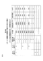
図23に示すように、パケット転送制御装置43のモードDB409には、各ノードのポートごとのモード情報が格納されている。図22に示されたノードのポートID=1には3つのモード(モードID=1、2、3)が定義され、それぞれの物理レイヤモードがIn方向リンクとOut方向リンクとに区別されて定義されている。たとえば、ポートID=1では、モードID=1でIn方向の容量が「160Mbps」、Out方向の容量が「80Mbps」、モードID=2でIn方向の容量が「120Mbps」、Out方向の容量が「120Mbps」であり、モードID=3でIn方向の容量が「80Mbps」、Out方向の容量が「160Mbps」である。なお、Availability、遅延および消費電力はいずれのモードでも同じである。したがって、物理レイヤモードを特定する情報(ここでは、ポートIDとモードIDとの組み合わせ)を用いて、当該ポートで満たすべきIn方向あるいはOut方向の物理レイヤ条件(容量)を指定することができる。
図23に示すように、パケット転送制御装置43のモードDB409には、各ノードのポートごとのモード情報が格納されている。図22に示されたノードのポートID=1には3つのモード(モードID=1、2、3)が定義され、それぞれの物理レイヤモードがIn方向リンクとOut方向リンクとに区別されて定義されている。たとえば、ポートID=1では、モードID=1でIn方向の容量が「160Mbps」、Out方向の容量が「80Mbps」、モードID=2でIn方向の容量が「120Mbps」、Out方向の容量が「120Mbps」であり、モードID=3でIn方向の容量が「80Mbps」、Out方向の容量が「160Mbps」である。なお、Availability、遅延および消費電力はいずれのモードでも同じである。したがって、物理レイヤモードを特定する情報(ここでは、ポートIDとモードIDとの組み合わせ)を用いて、当該ポートで満たすべきIn方向あるいはOut方向の物理レイヤ条件(容量)を指定することができる。
たとえば、午前中(6時~12時)はIn方向のトラフィックの方が大きく、午後(12時~18時)はIn方向とOut方向はほぼ同じトラフィックとなり、夜間(18時~翌朝6時)はOut方向のトラフィックの方が大きくなることが統計的に分かっていれば、午前中はポートID=1およびモードID=1を、午後はポートID=1およびモードID=2を、夜間はポートID=1およびモードID=3をそれぞれ指定する制御ポリシをパケット転送制御装置43に設定すればよい。
図24に示すように、パケット転送機能部52のモード管理DB507には、ポートごとに定義された各モードの通信インタフェース設定情報が格納されている。モード管理DB507におけるポートおよびモードの組み合わせは、パケット転送制御装置43のモードDB409で定義されたポートおよびモードの組み合わせに対応している。上述したように、ポートID=1およびモードID=1であれば、無線通信インタフェース部505のIn方向のたとえば参照送信パワーを増大させ、ポートID=1およびモードID=3であれば、無線通信インタフェース部505のOut方向のたとえば参照送信パワーを増大させる。
5.3)効果
本発明の第5実施形態によれば、上記第1~第4実施形態の効果に加えて、時間分割でノード間のリンク方向および物理レイヤ条件を変更することで、トラフィックの量および方向の時間的変動に応じてネットワークをより効率的に運用することが可能となる。
本発明の第5実施形態によれば、上記第1~第4実施形態の効果に加えて、時間分割でノード間のリンク方向および物理レイヤ条件を変更することで、トラフィックの量および方向の時間的変動に応じてネットワークをより効率的に運用することが可能となる。
本発明はSDN化されたトランスポート網のシステムに適用可能である。
10 制御装置
20 ネットワーク
30 管理装置
40~43 パケット転送制御装置
50~52 パケット転送機能部
101 ノード通信部
102 パケット転送ルールデータベース
103 モードデータベース
104 制御部
201 通信部
202 フローテーブル
203 パケット転送処理部
204 モード管理部
205 モード管理データベース
404 パケット転送ルールデータベース
409 モードデータベース
410 ポリシ記憶部
502 転送処理部
503 フローテーブル
505 通信インタフェース部
506 モード管理部
507 モード管理データベース
20 ネットワーク
30 管理装置
40~43 パケット転送制御装置
50~52 パケット転送機能部
101 ノード通信部
102 パケット転送ルールデータベース
103 モードデータベース
104 制御部
201 通信部
202 フローテーブル
203 パケット転送処理部
204 モード管理部
205 モード管理データベース
404 パケット転送ルールデータベース
409 モードデータベース
410 ポリシ記憶部
502 転送処理部
503 フローテーブル
505 通信インタフェース部
506 モード管理部
507 モード管理データベース
Claims (38)
- ネットワークを構成する複数のノードと、各ノードをフロー単位で制御する制御装置と、を有する通信システムであって、
前記ノードの各ポートに少なくとも1つの通信インタフェースが設けられ、
前記制御装置が、各ノードのポートごとに1つ以上の物理レイヤモードを保持し、あるノードの所定ポートの物理レイヤモードを所定の時間分割に従って変更して前記ノードへ通知し、
前記ノードが、前記制御装置から通知されたポートの物理レイヤモードに従って、対応する通信インタフェースを設定する、
ことを特徴とする通信システム。 - 前記制御装置が、前記ノードとその隣接ノードとの間のリンク方向を前記所定の時間分割に従って変更することを特徴とする請求項1に記載の通信システム。
- 前記制御装置が、所定の制御ポリシに従って前記所定の時間分割および指定すべき物理レイヤモードを決定することを特徴とする請求項1または2に記載の通信システム。
- 前記制御ポリシは前記ネットワークの各ノードから提供された統計情報に基づいて生成あるいは更新されることを特徴とする請求項3に記載の通信システム。
- 前記制御ポリシは前記ネットワークを管理する管理装置により提供されることを特徴とする請求項3または4に記載の通信システム。
- 前記ノードが、各ポートの1つ以上の物理レイヤモードと前記通信インタフェースの物理パラメータとを対応付けたテーブルを備えることを特徴とする請求項1-5のいずれか1項に記載の通信システム。
- 前記物理レイヤモードは前記ノードのポートに設けられた通信インタフェースが満たすべき動作条件に対応し、前記ノードが前記動作条件に応じて前記通信インタフェースの物理パラメータを設定する、ことを特徴とする請求項1-6のいずれか1項に記載の通信システム。
- 制御装置により制御されるネットワークのノード装置であって、
前記ネットワークとの間でパケットの送受信を行う複数のポートを有し、前記制御装置からのフロー単位の制御に従ってパケットの転送を行う転送手段と、
前記複数のポートの各々に設けられた少なくとも1つの通信インタフェースと、
前記制御装置からのモード指定情報に従って、指定されたポートの物理レイヤモードを指定された時間分割に従って変更し、当該ポートの通信インタフェースを設定するモード管理手段と、
を有することを特徴とするノード装置。 - 前記制御装置からのモード指定情報により、当該ノード装置とその隣接ノード装置との間のリンク方向を前記指定された時間分割に従って変更することを特徴とする請求項8に記載のノード装置。
- 前記モード管理手段が、各ポートの1つ以上の物理レイヤモードと通信インタフェースの物理パラメータとを対応付けたテーブルを備えることを特徴とする請求項8-9のいずれか1項に記載のノード装置。
- 前記物理レイヤモードは前記通信インタフェースが満たすべき動作条件に対応し、前記モード管理手段が前記動作条件に応じて前記通信インタフェースの物理パラメータを設定する、ことを特徴とする請求項8-10のいずれか1項に記載のノード装置。
- 前記通信インタフェースが少なくとも送信パワーを調整可能であることを特徴とする請求項8-11のいずれか1項に記載のノード装置。
- 前記通信インタフェースが複数の送受信部を有し、前記複数の送受信部を有効する個数により前記送信パワーを調整することを特徴とする請求項12に記載のノード装置。
- 前記通信インタフェースが少なくとも消費電力を調整可能であることを特徴とする請求項8-13のいずれか1項に記載のノード装置。
- ネットワークを構成する複数のノードの各々に対してフロー単位での制御を実行する制御装置であって、
前記ノードの各ポートに対して1つ以上の物理レイヤモードを保持したモードテーブルと、
あるノードの所定ポートの物理レイヤモードを所定の時間分割に従って変更して前記ノードへ通知するノード管理手段と、
を有することを特徴とする制御装置。 - 前記ノード管理手段が、前記ノードとその隣接ノードとの間のリンク方向を前記所定の時間分割に従って変更することを特徴とする請求項15に記載の制御装置。
- 前記ノード管理手段が、所定の制御ポリシに従って前記所定の時間分割および指定すべき物理レイヤモードを決定することを特徴とする請求項15または16に記載の制御装置。
- 前記制御ポリシは前記ネットワークの各ノードから提供された統計情報に基づいて生成あるいは更新されることを特徴とする請求項17に記載の制御装置。
- 前記制御ポリシは前記ネットワークを管理する管理装置により提供されることを特徴とする請求項17または18に記載の制御装置。
- 前記物理レイヤモードは前記ノードのポートに設けられた通信インタフェースが満たすべき動作条件に対応し、前記モード指定情報に従って前記ノードが前記動作条件に応じた前記通信インタフェースの設定を行うことを特徴とする請求項15-19のいずれか1項に記載の制御装置。
- ネットワークを構成する複数のノードと、各ノードをフロー単位で制御する制御装置と、を有する通信システムにおける通信制御方法であって、
前記ノードの各ポートに少なくとも1つの通信インタフェースが設けられ、
前記制御装置が、各ノードのポートごとに1つ以上の物理レイヤモードを保持し、あるノードの所定ポートの物理レイヤモードを所定の時間分割に従って変更して前記ノードへ通知し、
前記ノードが、前記制御装置から通知されたポートの物理レイヤモードに従って、対応する通信インタフェースを設定する、
ことを特徴とする通信制御方法。 - 前記制御装置が、前記ノードとその隣接ノードとの間のリンク方向を前記所定の時間分割に従って変更することを特徴とする請求項21に記載の通信制御方法。
- 前記制御装置が、所定の制御ポリシに従って前記所定の時間分割および指定すべき物理レイヤモードを決定することを特徴とする請求項21または22に記載の通信制御方法。
- 前記制御ポリシは前記ネットワークの各ノードから提供された統計情報に基づいて生成あるいは更新されることを特徴とする請求項23に記載の通信制御方法。
- 前記制御ポリシは前記ネットワークを管理する管理装置により提供されることを特徴とする請求項23または24に記載の通信制御方法。
- 前記ノードが、各ポートの1つ以上の物理レイヤモードと前記通信インタフェースの物理パラメータとを対応付けたテーブルを備えることを特徴とする請求項21-25のいずれか1項に記載の通信制御方法。
- 前記物理レイヤモードは前記ノードのポートに設けられた通信インタフェースが満たすべき動作条件に対応し、前記ノードが前記動作条件に応じて前記通信インタフェースの物理パラメータを設定する、ことを特徴とする請求項21-26のいずれか1項に記載の通信制御方法。
- 制御装置により制御されるネットワークとの間でパケットの送受信を行う複数のポートと、前記制御装置からのフロー単位の制御に従ってパケットの転送を行う転送手段と、前記複数のポートの各々に設けられた少なくとも1つの通信インタフェースと、を有するノード装置の通信制御方法であって、
前記制御装置からモード指定情報を受信し、
前記モード指定情報で指定されたポートの物理レイヤモードを指定された時間分割に従って変更し、
前記指定されたポートの変更された物理レイヤモードに従って前記ポートに設けられた通信インタフェースを設定する、
ことを特徴とする通信制御方法。 - 前記制御装置からのモード指定情報により、当該ノード装置とその隣接ノード装置との間のリンク方向を前記指定された時間分割に従って変更することを特徴とする請求項28に記載の通信制御方法。
- 前記モード指定情報に従って、各ポートの伝送方向ごとに1つ以上の物理レイヤモードと通信インタフェースの物理パラメータとを対応付けたテーブルを参照し、前記テーブルにより検索された前記物理パラメータにより前記通信インタフェースの設定を行うことを特徴とする請求項28または29に記載の通信制御方法。
- 前記物理レイヤモードは前記通信インタフェースが満たすべき動作条件に対応し、前記動作条件に応じて前記通信インタフェースの物理パラメータを設定することを特徴とする請求項28-30のいずれか1項に記載の通信制御方法。
- ネットワークを構成する複数のノードの各々をフロー単位で制御する制御方法であって、
モードテーブルが各ノードの各ポートに対して1つ以上の物理レイヤモードを保持し、
ノード管理手段が、あるノードの所定ポートの物理レイヤモードを所定の時間分割に従って変更して前記ノードへ通知する、
ことを特徴とする制御方法。 - 前記ノード管理手段が、前記ノードとその隣接ノードとの間のリンク方向を前記所定の時間分割に従って変更することを特徴とする請求項32に記載の制御方法。
- 前記ノード管理手段が、所定の制御ポリシに従って前記所定の時間分割および指定すべき物理レイヤモードを決定することを特徴とする請求項32または33に記載の制御方法。
- 前記制御ポリシは前記ネットワークの各ノードから提供された統計情報に基づいて生成あるいは更新されることを特徴とする請求項34に記載の制御方法。
- 前記制御ポリシは前記ネットワークを管理する管理装置により提供されることを特徴とする請求項34または35に記載の制御方法。
- 制御装置により制御されるネットワークとの間でパケットの送受信を行う複数のポートと、前記制御装置からのフロー単位の制御に従ってパケットの転送を行う転送手段と、前記複数のポートの各々に設けられた少なくとも1つの通信インタフェースと、を有するノード装置としてコンピュータを機能させるプログラムであって、
前記制御装置からモード指定情報を受信する機能と、
前記モード指定情報で指定されたポートの物理レイヤモードを指定された時間分割に従って変更する機能と、
前記指定されたポートの変更された物理レイヤモードに従って前記ポートに設けられた通信インタフェースを設定する機能と、
を前記コンピュータに実現するためのプログラム。 - ネットワークを構成する複数のノードの各々に対してフロー単位での制御を実行する制御装置としてコンピュータを機能させるためのプログラムであって、
前記ノードの各ポートに対して1つ以上の物理レイヤモードをモードテーブルに保持する機能と、
ノード管理手段が、あるノードの所定ポートの物理レイヤモードを所定の時間分割に従って変更して前記ノードへ通知する機能と、
を前記コンピュータに実現するためのプログラム。
Applications Claiming Priority (2)
| Application Number | Priority Date | Filing Date | Title |
|---|---|---|---|
| JP2015068487 | 2015-03-30 | ||
| JP2015-068487 | 2015-03-30 |
Publications (1)
| Publication Number | Publication Date |
|---|---|
| WO2016157844A1 true WO2016157844A1 (ja) | 2016-10-06 |
Family
ID=57005494
Family Applications (1)
| Application Number | Title | Priority Date | Filing Date |
|---|---|---|---|
| PCT/JP2016/001704 Ceased WO2016157844A1 (ja) | 2015-03-30 | 2016-03-24 | ネットワークシステム、ノード装置、制御装置、通信制御方法および制御方法 |
Country Status (1)
| Country | Link |
|---|---|
| WO (1) | WO2016157844A1 (ja) |
Cited By (1)
| Publication number | Priority date | Publication date | Assignee | Title |
|---|---|---|---|---|
| WO2021225134A1 (ja) | 2020-05-07 | 2021-11-11 | 日本電気通信システム株式会社 | ネットワーク制御装置、ネットワーク制御方法およびネットワーク制御プログラム |
-
2016
- 2016-03-24 WO PCT/JP2016/001704 patent/WO2016157844A1/ja not_active Ceased
Non-Patent Citations (3)
| Title |
|---|
| GUIMARAES, CARLOS ET AL.: "Enhancing OpenFlow with Media Independent Management Capabilities", 2014 IEEE INTERNATIONAL CONFERENCE ON COMMUNICATIONS (ICC, June 2014 (2014-06-01), pages 2995 - 3000, XP032632091, Retrieved from the Internet <URL:http://ieeexplore.ieee.org/xpls/abs_all.jsp?arnumber=6883780> [retrieved on 20160526] * |
| MASAO NISHIE ET AL.: "Development and Evaluation of SDN Technologies for Offering Value-Added Network Services", IEICE TECHNICAL REPORT, vol. 114, no. 523, 12 March 2015 (2015-03-12), pages 31 - 36 * |
| ZHANG, SHENGLI ET AL.: "SDN BASED UNIFORM NETWORK ARCHITECTURE FOR FUTURE WIRELESS NETWORKS", 2014 INTERNATIONAL CONFERENCE ON COMPUTING, COMMUNICATION AND NETWORKING TECHNOLOGIES (ICCCNT, July 2014 (2014-07-01), XP032687406, Retrieved from the Internet <URL:http://ieeexplore.ieee.org/xpls/abs_all.jsp?arnumber=6963056> [retrieved on 20160526] * |
Cited By (2)
| Publication number | Priority date | Publication date | Assignee | Title |
|---|---|---|---|---|
| WO2021225134A1 (ja) | 2020-05-07 | 2021-11-11 | 日本電気通信システム株式会社 | ネットワーク制御装置、ネットワーク制御方法およびネットワーク制御プログラム |
| US12184436B2 (en) | 2020-05-07 | 2024-12-31 | Nec Communication Systems, Ltd. | Network control apparatus, network control method, and network control program |
Similar Documents
| Publication | Publication Date | Title |
|---|---|---|
| US11134012B2 (en) | Communication system, communication device, controller, and method and program for controlling forwarding path of packet flow | |
| US10972357B2 (en) | SDN network system, controller, and controlling method | |
| KR101989333B1 (ko) | 소프트웨어 정의 네트워킹에서의 데이터 전달 방법, 기기 및 시스템 | |
| JP5488980B2 (ja) | コンピュータシステム、及び通信方法 | |
| US20140211661A1 (en) | Automatic Discovery of Multiple Controllers in Software Defined Networks (SDNs) | |
| KR101665276B1 (ko) | 가상 섀시 시스템에서 패스 스루 모드를 위한 시스템 및 방법 | |
| JP6072278B2 (ja) | 仮想シャーシシステム制御プロトコル | |
| CN104054304A (zh) | 计算机系统、控制器、交换机、通信方法以及存储网络管理程序的记录介质 | |
| CN109089294B (zh) | 一种基于sdn分布式控制的无人机网络流量配置方法及系统 | |
| WO2012050071A1 (ja) | 通信システム、制御装置、処理規則の設定方法およびプログラム | |
| CN106059793A (zh) | 一种基于平滑重启的路由信息处理方法及装置 | |
| JP2010263395A (ja) | ネットワーク中継機器及びリングネットワーク | |
| CN101466126A (zh) | 路由控制方法、主机设备、路由器和路由控制系统 | |
| JP2017503408A (ja) | 通信ネットワーク内の制御を提供する方法 | |
| CN107070791A (zh) | 一种sdn网络系统及其数据传输方法 | |
| JP6751272B2 (ja) | ネットワークシステム、ノード装置、制御装置、通信制御方法および制御方法 | |
| WO2016157844A1 (ja) | ネットワークシステム、ノード装置、制御装置、通信制御方法および制御方法 | |
| WO2016157846A1 (ja) | ネットワークシステム、ノード装置、制御装置、通信制御方法および制御方法 | |
| WO2016157845A1 (ja) | ネットワークシステム、ノード装置、制御装置、通信制御方法および制御方法 | |
| CN100461764C (zh) | 实现报文转发路径一致的方法和系统 | |
| US8817638B2 (en) | Method and system for network communications utilizing shared scalable resources | |
| JP2017103519A (ja) | 制御装置、通信システム、制御方法及びプログラム | |
| Mancuso et al. | CVS: using VLANs to counteract the effect of topology changes in quasi-static mesh access networks | |
| HK1153877B (en) | Method and system for network |
Legal Events
| Date | Code | Title | Description |
|---|---|---|---|
| 121 | Ep: the epo has been informed by wipo that ep was designated in this application |
Ref document number: 16771734 Country of ref document: EP Kind code of ref document: A1 |
|
| NENP | Non-entry into the national phase |
Ref country code: DE |
|
| 122 | Ep: pct application non-entry in european phase |
Ref document number: 16771734 Country of ref document: EP Kind code of ref document: A1 |
|
| NENP | Non-entry into the national phase |
Ref country code: JP |