WO2016153084A1 - 2차원 디스플레이로 변환 가능한 시야창 방식 홀로그래픽 디스플레이 시스템 - Google Patents
2차원 디스플레이로 변환 가능한 시야창 방식 홀로그래픽 디스플레이 시스템 Download PDFInfo
- Publication number
- WO2016153084A1 WO2016153084A1 PCT/KR2015/002745 KR2015002745W WO2016153084A1 WO 2016153084 A1 WO2016153084 A1 WO 2016153084A1 KR 2015002745 W KR2015002745 W KR 2015002745W WO 2016153084 A1 WO2016153084 A1 WO 2016153084A1
- Authority
- WO
- WIPO (PCT)
- Prior art keywords
- modulator
- plane wave
- holographic
- display system
- fringe pattern
- Prior art date
- Legal status (The legal status is an assumption and is not a legal conclusion. Google has not performed a legal analysis and makes no representation as to the accuracy of the status listed.)
- Ceased
Links
Images



Classifications
-
- G—PHYSICS
- G02—OPTICS
- G02B—OPTICAL ELEMENTS, SYSTEMS OR APPARATUS
- G02B30/00—Optical systems or apparatus for producing three-dimensional [3D] effects, e.g. stereoscopic images
-
- G—PHYSICS
- G02—OPTICS
- G02B—OPTICAL ELEMENTS, SYSTEMS OR APPARATUS
- G02B5/00—Optical elements other than lenses
- G02B5/32—Holograms used as optical elements
Definitions
- the present invention relates to a display system, and more particularly to a holographic display system.
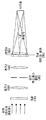
- FIG. 1 is a diagram illustrating a diffraction angle of a hologram display.
- the diffraction angle ⁇ is determined by the pixel size, which is inversely proportional to the pixel size.
- SLM Spatial Light Modulator
- FOV field of view
- a holographic display in the form of a viewing window as shown in FIG. 2 has recently appeared. This method collects light diffracted from each pixel of the SLM 10 in one small field of view using the lens 60 to secure a wide field of view instead of limiting the position of the observer.
- the laser plane wave is diffracted by the hologram displayed on the SLM 10, and the diffracted light is converted into the frequency domain in the plane located at the focal length by the lens 1 20.
- the spatial bandpass filter 30 By placing the spatial bandpass filter 30 in the frequency domain, we obtain only the complex wave from which the DC term has been removed, and again the image of the SLM 10 by lens 2 40 causes the image of the SLM image plane just in front of lens 3 60. It will be formed at 50.
- the light diffracted from each pixel of the SLM's image generated in the SLM image plane 50 is collected by the lens 3 (60) in the field of view so that if the observer is in the field of view, the entire area of the SLM is independent of the size of the SLM. Through the hologram can be observed.
- the observer can only observe the hologram by placing the pupil within the field of view. Therefore, the viewing window hologram is easy to provide a holographic image, but the user may feel uncomfortable, and thus, when the commercialization is considered, it is necessary to switch to the ordinary two-dimensional display.
- the present invention has been made to solve the above problems, and an object of the present invention is to provide a holographic display system that can be converted into a two-dimensional display.
- a holographic display system includes: a first modulator for generating a holographic fringe pattern; A second modulator for transmitting all or part of the plane wave transmitted through the fringe pattern; And LC (Liquid Crystal) for transmitting or scattering the plane wave transmitted through the second modulator.
- a first modulator for generating a holographic fringe pattern
- a second modulator for transmitting all or part of the plane wave transmitted through the fringe pattern
- LC Liquid Crystal
- the second modulator may partially transmit the plane wave transmitted through the fringe pattern, and the LC may transmit the plane wave transmitted through the second modulator.
- the second modulator may transmit all the plane waves transmitted through the fringe pattern, and the LC may scatter the plane waves transmitted through the second modulator.
- the LC may transition to a diffuser state to scatter the plane wave.
- the second modulator may function as a spatial bandpass filter that generates an image in which the rest of the circular part or the rectangular part is black, and transmits only the circular part or the rectangular part.
- the first modulator may be a reflective or transmissive spatial light modulator.
- the holographic display system may further include a lens provided at the front end of the LC to collect the plane wave transmitted through the second modulator in the viewing window.
- the holographic display method generating a holographic fringe pattern; Transmitting all or part of the plane wave transmitted through the fringe pattern; And transmitting or scattering the plane wave transmitted in the transmission step.
- the prior art window holographic display is only capable of providing a three-dimensional holographic image at a very limited viewing position, but according to embodiments of the present invention, a two-dimensional display of a window holographic display according to a user's preference is provided. Can be converted to function.
- 1 is a diagram showing a diffraction angle of a hologram display
- FIG. 2 is a view showing a viewing window hologram display
- FIG. 3 is a view illustrating a viewing window holographic display system according to an embodiment of the present invention.
- FIG. 5 is a view showing a state of a sight window type holographic display system according to an embodiment of the present invention in a three-dimensional mode
- FIG. 6 is a view illustrating a state of a sight window type holographic display system according to an exemplary embodiment of the present invention in a two-dimensional mode.
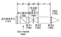
- FIG. 3 is a diagram illustrating a viewing window holographic display system according to an exemplary embodiment of the present invention.
- the holographic display system according to an embodiment of the present invention can be converted into a two-dimensional display system.
- a sight window type holographic display system includes a spatial light modulator (SLM) 110, a beam splitter 120, a lens 1 130, A transmissive spatial light modulator 140, a lens 2 150, a lens 3 160, and a polymer-dispersed liquid crystal (PDLC) 170.
- SLM spatial light modulator
- PDLC polymer-dispersed liquid crystal
- Lens 1 130, lens 2 150, and lens 3 160 have the same focal length F.
- the spatial light modulator 110 assumes a reflective spatial light modulator, which is merely exemplary.
- the spatial light modulator 110 is replaceable with a transmissive spatial light modulator. In this case, however, it is required to remove the beam splitter 120 and irradiate the collimated laser behind the spatial light modulator 110.
- the viewing window holographic display system according to the exemplary embodiment of the present invention illustrated in FIG. 2 Unlike the conventional viewing window holographic display system illustrated in FIG. 2, the viewing window holographic display system according to the exemplary embodiment of the present invention illustrated in FIG.
- the transmissive spatial light modulator 140 is located in place of the spatial bandpass filter
- PDLC 170 is located in front (rear) of lens 3 (160).
- the transmissive spatial light modulator 140 may be implemented using an LC panel, and the PDLC 170 is an LC device that is transferred to a transparent state or a diffuser state (semi-transparent state) according to whether a voltage is applied.
- the three-dimensional mode is a mode in which the field of view holographic display system according to an embodiment of the present invention performs its original function.
- the transmissive spatial light modulator 140 needs to generate an image as shown in FIG. 4.
- FIG. 4 (a) is an image in which the square part of the upper right is transparent and the remaining parts are black
- FIG. 4 (b) is an image in which the circular part of the upper right is transparent and the remaining parts are black.
- the transmissive spatial light modulator 140 can function as a spatial bandpass filter.
- FIG. 5 is a view illustrating a state of a sight window type holographic display system according to an exemplary embodiment of the present invention in a 3D mode.
- the transmissive spatial light modulator 140 in the three-dimensional mode, generates an image as shown in FIG. 4 to function as a spatial bandpass filter, and the PDLC 170 is set to transparent. It works.
- the laser plane wave transmitted therethrough is focused by the lens 1 130 through the beam splitter 120, and thus is transparent by the transparent portion of the transmissive spatial light modulator 140. Only part of the light is transmitted (filtered) and converted in parallel through the lens 2 150 to be collected in the viewing window by the lens 3 160.
- the PDLC 170 since the PDLC 170 is in a transparent state, the holographic image by the holographic pattern is transmitted without being affected by the PDLC 170.
- the observer existing in the viewing window may observe the 3D hologram image by the holographic fringe pattern generated by the spatial light modulator 110.
- FIG. 6 is a view illustrating a state of a sight window type holographic display system according to an exemplary embodiment of the present invention in a two-dimensional mode.
- the two-dimensional mode is a mode in which a viewing window holographic display system according to an exemplary embodiment of the present invention functions as a two-dimensional display to provide a viewer with a two-dimensional image.
- the transmissive spatial light modulator 140 needs to generate an image in which the entire area is transparent. Then, the transmissive spatial light modulator 140 functions as a transparent glass window that transmits all light.
- the PDLC 170 is set to the diffuser state (translucent state). As a result, the PDLC 170 scatters incident light.
- the laser plane wave transmitted through the spatial light modulator 110 is focused on the lens 1 130 through the beam splitter 120, and passes through the transmissive spatial light modulator 140.
- the 3D hologram image by the holographic fringe pattern generated by the spatial light modulator 110 is formed on the lens 3 160 by the principle of the 4f system.
- This three-dimensional holographic image will be collected in the field of view by lens 3 (160). However, since the PDLC 170 is in a diffuser state (translucent state) such as oil paper, the 3D hologram image is scattered and converted into a 2D image.
- a diffuser state translucent state
- the observer existing in the viewing window may observe the holographic image generated by the holographic fringe pattern generated by the spatial light modulator 110 in two dimensions.
- the elements that are the centers of the display type change are implemented by the transmissive spatial light modulator 140 and the PDLC 170, which are electronic elements, which is merely exemplary.
- the transmissive spatial light modulator 140 it is possible to implement the transmissive spatial light modulator 140 as a device whose function is mechanically converted. That is, the spatial band pass filter and the transparent glass are provided in one panel, and by rotating or moving the panel, the spatial band pass filter is positioned on the optical path in the 3D mode, and on the optical path in the 2D mode. It is possible to drive the transparent glass to be located.
- the PDLC 170 may also be implemented as a device whose function is mechanically converted.
- the transparent glass and the diffuser are provided in one panel, and by rotating or moving the panel, the transparent glass is positioned on the optical path in the 3D mode, and the diffuser is positioned on the optical path in the 2D mode. It is possible to let.
Landscapes
- Physics & Mathematics (AREA)
- General Physics & Mathematics (AREA)
- Optics & Photonics (AREA)
- Holo Graphy (AREA)
Abstract
2차원 디스플레이로 변환가능한 시야창 방식 홀로그래픽 디스플레이 시스템이 제공된다. 본 발명의 실시예에 따른 홀로그래픽 디스플레이 시스템은, 홀로그래픽 프린지 패턴을 생성하고, 프린지 패턴을 투과한 평면파를 전부 또는 일부 투과시키는 변조기;와 변조기를 투과한 평면파를 투과 또는 산란시키는 LC 소자를 포함한다. 종래 기술인 시야창 방식 홀로그래픽 디스플레이는 매우 제한된 관찰 위치에서 3차원 홀로그램 영상을 제공하는 것만이 가능하지만, 본 발명의 실시예들에 따르면, 사용자의 선호에 따라 시야창 방식 홀로그래픽 디스플레이를 2차원 디스플레이로써 기능하도록 변환할 수 있게 된다.
Description
본 발명은 디스플레이 시스템에 관한 것으로, 더욱 상세하게는 홀로그래픽 디스플레이 시스템에 관한 것이다.
도 1은 홀로그램 디스플레이의 회절각을 나타낸 도면이다. 도 1에 도시된 바와 같이 기존의 홀로그램 디스플레이는 픽셀 크기에 의해 회절각 θ가 결정되며, 이는 픽셀 크기에 반비례한다.
보통 현재 기술 수준의 SLM(Spatial Light Modulator)(10)으로는 보통 수 도(°) 정도의 회절각 밖에 제공할 수가 없는데, 이에 따라 관찰자가 관찰할 수 있는 FOV(Field Of View)는 극히 제한되게 된다.
넓은 FOV를 제공하기 위해, 최근 도 2에 도시된 바와 같은 시야창 방식의 홀로그램 디스플레이가 등장하였다. 이는, SLM(10)의 각 픽셀로부터 회절되는 빛을 렌즈(60)를 이용해 하나의 작은 시야창에 모아줌으로써 관찰자의 위치를 제한하는 대신 넓은 FOV를 확보하는 방법이다.
도 2에서 레이저 평면파가 SLM(10)에 표시된 홀로그램에 의해 회절되고, 회절된 빛은 렌즈 1(20)에 의해 초점거리에 위치한 면에서 주파수 영역으로 변환되게 된다. 이때. 주파수 영역에 공간밴드패스 필터(30)를 위치시킴으로써 DC term이 제거된 complex wave만을 얻게 되며, 다시 렌즈 2(40)에 의해 SLM(10)의 이미지가 렌즈 3(60) 바로 앞의 SLM 이미지 평면(50)에 형성되게 된다.
SLM 이미지 평면(50)에 생성된 SLM의 이미지의 각 픽셀로부터 회절된 빛이 렌즈 3(60)에 의해 시야창에 모두 모이게 됨으로써 관찰자가 시야창 안에 존재할 경우 SLM의 크기에 관계없이 SLM의 전체 영역을 통해 홀로그램을 관찰할 수 있게 된다.
하지만, 관찰자는 시야창 안에 동공을 위치시켜야만 홀로그램을 관찰할 수 있다. 따라서, 시야창 방식 홀로그램은 홀로그램 영상을 제공함에 있어서는 용이하지만 사용자가 불편을 느낄 수 있기 때문에 상용화를 고려한다면 평범한 2차원 디스플레이로의 전환이 필요한 실정이다.
본 발명은 상기와 같은 문제점을 해결하기 위하여 안출된 것으로서, 본 발명의 목적은, 2차원 디스플레이로 변환 가능한 시야창 방식 홀로그래픽 디스플레이 시스템을 제공함에 있다.
상기 목적을 달성하기 위한 본 발명의 일 실시예에 따른, 홀로그래픽 디스플레이 시스템은, 홀로그래픽 프린지 패턴을 생성하는 제1 변조기; 상기 프린지 패턴을 투과한 평면파를 전부 또는 일부 투과시키는 제2 변조기; 및 상기 제2 변조기를 투과한 평면파를 투과 또는 산란시키는 LC(Liquid Crystal);를 포함한다.
그리고, 3차원 모드의 경우, 상기 제2 변조기는, 상기 프린지 패턴을 투과한 평면파를 일부 투과시키고, 상기 LC는, 상기 제2 변조기를 투과한 평면파를 투과시킬 수 있다.
또한, 2차원 모드의 경우, 상기 제2 변조기는, 상기 프린지 패턴을 투과한 평면파를 전부 투과시키고, 상기 LC는, 상기 제2 변조기를 투과한 평면파를 산란시킬 수 있다.
그리고, 상기 LC는, 디퓨저 상태로 전이되어, 상기 평면파를 산란시킬 수 있다.
또한, 상기 제2 변조기는, 원형 부분 또는 사각형 부분을 제외한 나머지가 검정색으로 나타낸 이미지를 생성하여, 원형 부분 또는 사각형 부분만을 투과시키는 공간 밴드패스 필터로 기능할 수 있다.
그리고, 상기 제1 변조기는, 반사형 또는 투과형 공간 광 변조기일 수 있다.
또한, 본 발명의 일 실시예에 따른 홀로그래픽 디스플레이 시스템은, 상기 LC의 전단에 마련되어, 상기 제2 변조기를 투과한 평면파를 시야창에 모여지게 하는 렌즈;를 더 포함할 수 있다.
한편, 본 발명의 다른 실시예에 따른, 홀로그래픽 디스플레이 방법은, 홀로그래픽 프린지 패턴을 생성하는 단계; 상기 프린지 패턴을 투과한 평면파를 전부 또는 일부 투과시키는 단계; 및 상기 투과 단계에서 투과된 평면파를 투과 또는 산란시키는 단계;를 포함한다.
종래 기술인 시야창 방식 홀로그래픽 디스플레이는 매우 제한된 관찰 위치에서 3차원 홀로그램 영상을 제공하는 것만이 가능하지만, 본 발명의 실시예들에 따르면, 사용자의 선호에 따라 시야창 방식 홀로그래픽 디스플레이를 2차원 디스플레이로써 기능하도록 변환할 수 있게 된다.
도 1은 홀로그램 디스플레이의 회절각을 나타낸 도면,
도 2는 시야창 방식 홀로그램 디스플레이를 나타낸 도면,
도 3은 본 발명의 일 실시예에 따른 시야창 방식 홀로그래픽 디스플레이 시스템을 도시한 도면,
도 4는 3차원 모드를 위한 투과형 공간 광변조기에 생성되는 이미지들을 예시한 도면,
도 5는 3차원 모드에서 본 발명의 실시예에 따른 시야창 방식 홀로그래픽 디스플레이 시스템의 상태를 나타낸 도면, 그리고,
도 6은 2차원 모드에서 본 발명의 실시예에 따른 시야창 방식 홀로그래픽 디스플레이 시스템의 상태를 나타낸 도면이다.
이하에서는 도면을 참조하여 본 발명을 보다 상세하게 설명한다.
도 3은 본 발명의 일 실시예에 따른 시야창 방식 홀로그래픽 디스플레이 시스템을 도시한 도면이다. 본 발명의 실시예에 따른 시야창 방식 홀로그래픽 디스플레이 시스템은, 2차원 디스플레이 시스템으로 변환이 가능하다.
본 발명의 실시예에 따른 시야창 방식 홀로그래픽 디스플레이 시스템은, 도 3에 도시된 바와 같이, 공간 광 변조기(Spatial Light Modulator : SLM)(110), 빔 스플리터(120), 렌즈 1(130), 투과형 공간 광 변조기(140), 렌즈 2(150), 렌즈 3(160) 및 PDLC(Polymer-Dispersed Liquid Crystal)(170)를 포함한다.
렌즈 1(130), 렌즈 2(150) 및 렌즈 3(160)은 동일한 초점거리 F를 갖는다. 또한, 도 3에서 공간 광 변조기(110)는 반사형 공간 광 변조기를 상정하였는데, 예시적인 것에 불과하다. 공간 광 변조기(110)은 투과형 공간 광변조기로 대체가능하다. 단, 이 경우에는 빔 스플리터(120)를 제거하고 collimated laser를 공간 광 변조기(110)의 뒤에서 조사하여 줄 것이 요구된다.
도 2에 도시된 기존의 시야창 방식 홀로그래픽 디스플레이 시스템과 달리, 도 3에 도시된 본 발명의 일 실시예에 따른 시야창 방식 홀로그래픽 디스플레이 시스템은,
1) 공간 밴드패스 필터 대신에 투과형 공간 광 변조기(140)가 위치하고,
2) 렌즈 3(160)의 앞(후단)에 PDLC(170)가 위치한다.
투과형 공간 광 변조기(140)는 LC 패널을 이용하여 구현할 수 있으며, PDLC(170)는 전압 인가 여부에 따라 투명한 상태 또는 디퓨저(Diffuser) 상태(반투명 상태)로 전이되는 LC 소자이다.
도 4는 3차원 모드를 위한 투과형 공간 광변조기(140)에 생성되는 이미지들을 예시한 도면이다. 3차원 모드는 본 발명의 실시예에 따른 시야창 방식 홀로그래픽 디스플레이 시스템이 본연의 기능을 수행하는 모드이다.
본 발명의 실시예에 따른 시야창 방식 홀로그래픽 디스플레이 시스템이 3차원 모드로 동작하기 위해서는, 투과형 공간 광변조기(140)가 도 4에 도시된 바와 같은 이미지를 생성하여야 한다.
도 4의 (a)는 우측 상부의 사각형 부분은 투명하게 나머지 부분은 검정색으로 나타낸 이미지이고, 도 4의 (b)는 우측 상부의 원형 부분은 투명하게 나머지 부분은 검정색으로 나타낸 이미지이다.
(a) 타입의 이미지와 (b) 타입의 이미지 중 어느 타입의 이미지를 이용할지는 홀로그램 영상 정보에 따라 결정할 수 있다. 도 4에 도시된 이미지를 생성함으로써 투과형 공간 광 변조기(140)는 공간 밴드패스 필터로 기능할 수 있게 된다.
도 5는 3차원 모드에서 본 발명의 실시예에 따른 시야창 방식 홀로그래픽 디스플레이 시스템의 상태를 나타낸 도면이다.
도 5에 도시된 바와 같이, 3차원 모드에서는, 투과형 공간 광변조기(140)는 도 4에 도시된 바와 같은 이미지를 생성하여 공간 밴드패스 필터로 기능하고, PDLC(170)는 투명 상태로 설정/동작한다.
이에, 공간 광 변조기(110)에서 홀로그래픽 프린지 패턴을 생성하면, 이를 투과한 레이저 평면파가 빔 스플리터(120)를 통해 렌즈 1(130)에서 포커싱 되어 투과형 공간 광 변조기(140)의 투명한 부분에 의해 일부만 투과(필터링)하고, 렌즈 2(150)를 통해 평행하게 변환되어, 렌즈 3(160)에 의해 시야창에 모두 모여지게 된다.
이때, PDLC(170)는 투명 상태이므로, 홀로그래픽 패턴에 의한 홀로그램 영상은 PDLC(170)에 의해 영향받지 않고 그대로 투과한다.
이에 의해, 시야창 안에 존재하는 관찰자는 공간 광 변조기(110)에서 생성된 홀로그래픽 프린지 패턴에 의한 3차원 홀로그램 영상을 관찰할 수 있게 된다.
도 6은 2차원 모드에서 본 발명의 실시예에 따른 시야창 방식 홀로그래픽 디스플레이 시스템의 상태를 나타낸 도면이다. 2차원 모드는 본 발명의 실시예에 따른 시야창 방식 홀로그래픽 디스플레이 시스템이 2차원 디스플레이로 기능하여 관찰자에게 2차원 영상을 제공하는 모드이다.
본 발명의 실시예에 따른 시야창 방식 홀로그래픽 디스플레이 시스템이 2차원 모드로 동작하기 위해서는, 투과형 공간 광변조기(140)가 전 영역이 투명한 이미지를 생성하여야 한다. 그러면, 투과형 공간 광변조기(140)는 모든 빛을 투과시키는 투명한 유리창과 같이 기능하게 된다.
또한, PDLC(170)는 디퓨저 상태(반투명 상태)로 설정한다. 이에, PDLC(170)는 입사되는 빛을 산란시키게 된다.
공간 광 변조기(110)에서 홀로그래픽 프린지 패턴을 생성하면, 이를 투과한 레이저 평면파가 빔 스플리터(120)를 통해 렌즈 1(130)에서 포커싱 되어 투과형 공간 광 변조기(140)를 통과하고, 렌즈 2(150)를 통해 평행하게 변환되어, 4f 시스템의 원리에 의해 렌즈 3(160)에는 공간 광 변조기(110)에서 생성한 홀로그래픽 프린지 패턴에 의한 3차원 홀로그램 영상이 그대로 맺혀진다.
이 3차원 홀로그램 영상은 렌즈 3(160)에 의해 시야창에 모두 모여지게 될 것이다. 하지만, PDLC(170)는 기름 종이와 같은 디퓨저 상태(반투명 상태)이기 때문에, 3차원 홀로그램 영상이 산란되어 2차원 영상으로 변환된다.
이에 의해, 시야창 안에 존재하는 관찰자는 공간 광 변조기(110)에서 생성된 홀로그래픽 프린지 패턴에 의한 홀로그램 영상을 2차원으로 관찰할 수 있게 된다.
지금까지, 2차원 디스플레이로 변환가능한 시야창 방식 홀로그래픽 디스플레이 시스템에 대해 바람직한 실시예를 들어 상세히 설명하였다.
위 실시예에서, 디스플레이 타입 변경의 중심이 되는 소자들을 전자식 소자들인 투과형 공간 광 변조기(140)와 PDLC(170)로 구현하였는데, 이는 예시적인 것에 불과하다.
투과형 공간 광 변조기(140)를 기구적으로 기능이 변환되는 소자로 구현하는 것이 가능하다. 즉, 공간밴드패스 필터와 투명 유리를 하나의 패널에 마련하고, 패널의 회전이나 이동에 의해, 3차원 모드에서는 광 경로 상에 공간밴드패스 필터가 위치하도록 하고, 2차원 모드에서는 광 경로 상에 투명 유리가 위치하도록 구동시키는 것이 가능하다.
나아가, PDLC(170) 역시 기구적으로 기능이 변환되는 소자로 구현하는 것이 가능하다. 즉, 투명 유리와 디퓨저를 하나의 패널에 마련하고, 패널의 회전이나 이동에 의해, 3차원 모드에서는 광 경로 상에 투명 유리가 위치하도록 하고, 2차원 모드에서는 광 경로 상에 디퓨저가 위치하도록 구동시키는 것이 가능하다.
또한, 이상에서는 본 발명의 바람직한 실시예에 대하여 도시하고 설명하였지만, 본 발명은 상술한 특정의 실시예에 한정되지 아니하며, 청구범위에서 청구하는 본 발명의 요지를 벗어남이 없이 당해 발명이 속하는 기술분야에서 통상의 지식을 가진자에 의해 다양한 변형실시가 가능한 것은 물론이고, 이러한 변형실시들은 본 발명의 기술적 사상이나 전망으로부터 개별적으로 이해되어져서는 안될 것이다.
Claims (8)
- 홀로그래픽 프린지 패턴을 생성하는 제1 변조기;상기 프린지 패턴을 투과한 평면파를 전부 또는 일부 투과시키는 제2 변조기; 및상기 제2 변조기를 투과한 평면파를 투과 또는 산란시키는 LC(Liquid Crystal);를 포함하는 것을 특징으로 하는 홀로그래픽 디스플레이 시스템.
- 청구항 1에 있어서,3차원 모드의 경우,상기 제2 변조기는,상기 프린지 패턴을 투과한 평면파를 일부 투과시키고,상기 LC는,상기 제2 변조기를 투과한 평면파를 투과시키는 것을 특징으로 하는 홀로그래픽 디스플레이 시스템.
- 청구항 2에 있어서,2차원 모드의 경우,상기 제2 변조기는,상기 프린지 패턴을 투과한 평면파를 전부 투과시키고,상기 LC는,상기 제2 변조기를 투과한 평면파를 산란시키는 것을 특징으로 하는 홀로그래픽 디스플레이 시스템.
- 청구항 3에 있어서,상기 LC는,디퓨저 상태로 전이되어, 상기 평면파를 산란시키는 것을 특징으로 하는 홀로그래픽 디스플레이 시스템.
- 청구항 2에 있어서,상기 제2 변조기는,원형 부분 또는 사각형 부분을 제외한 나머지가 검정색으로 나타낸 이미지를 생성하여, 원형 부분 또는 사각형 부분만을 투과시키는 공간 밴드패스 필터로 기능하는 것을 특징으로 하는 홀로그래픽 디스플레이 시스템.
- 청구항 1에 있어서,상기 제1 변조기는,반사형 또는 투과형 공간 광 변조기인 것을 특징으로 하는 홀로그래픽 디스플레이 시스템.
- 청구항 1에 있어서,상기 LC의 전단에 마련되어, 상기 제2 변조기를 투과한 평면파를 시야창에 모여지게 하는 렌즈;를 더 포함하는 것을 특징으로 하는 홀로그래픽 디스플레이 시스템.
- 홀로그래픽 프린지 패턴을 생성하는 단계;상기 프린지 패턴을 투과한 평면파를 전부 또는 일부 투과시키는 단계; 및상기 투과 단계에서 투과된 평면파를 투과 또는 산란시키는 단계;를 포함하는 것을 특징으로 하는 홀로그래픽 디스플레이 방법.
Applications Claiming Priority (2)
| Application Number | Priority Date | Filing Date | Title |
|---|---|---|---|
| KR1020150038645A KR101679709B1 (ko) | 2015-03-20 | 2015-03-20 | 2차원 디스플레이로 변환 가능한 시야창 방식 홀로그래픽 디스플레이 시스템 |
| KR10-2015-0038645 | 2015-03-20 |
Publications (1)
| Publication Number | Publication Date |
|---|---|
| WO2016153084A1 true WO2016153084A1 (ko) | 2016-09-29 |
Family
ID=56977404
Family Applications (1)
| Application Number | Title | Priority Date | Filing Date |
|---|---|---|---|
| PCT/KR2015/002745 Ceased WO2016153084A1 (ko) | 2015-03-20 | 2015-03-20 | 2차원 디스플레이로 변환 가능한 시야창 방식 홀로그래픽 디스플레이 시스템 |
Country Status (2)
| Country | Link |
|---|---|
| KR (1) | KR101679709B1 (ko) |
| WO (1) | WO2016153084A1 (ko) |
Families Citing this family (4)
| Publication number | Priority date | Publication date | Assignee | Title |
|---|---|---|---|---|
| KR102633622B1 (ko) * | 2017-02-13 | 2024-02-02 | 시리얼 테크놀로지즈 에스.에이. | 광 가이드 디바이스 및 장면을 표현하기 위한 디스플레이 디바이스 |
| KR102021201B1 (ko) * | 2017-12-11 | 2019-09-11 | 전자부품연구원 | 집적영상과 홀로그래피를 이용한 3차원 디스플레이 시스템 및 방법 |
| KR102768060B1 (ko) * | 2017-12-28 | 2025-02-18 | 한국전자통신연구원 | 홀로그램 디스플레이 장치 및 그 방법 |
| KR20220102324A (ko) * | 2021-01-12 | 2022-07-20 | 정홍준 | 투명 디스플레이 패널을 이용한 현미경의 투과광 형성장치 |
Citations (5)
| Publication number | Priority date | Publication date | Assignee | Title |
|---|---|---|---|---|
| JPH07281214A (ja) * | 1994-02-18 | 1995-10-27 | Nippon Telegr & Teleph Corp <Ntt> | 光スイッチ |
| KR20080022193A (ko) * | 2005-06-13 | 2008-03-10 | 에이에스엠엘 네델란즈 비.브이. | 리소그래피 투영 시스템 및 투영 렌즈 편광 센서 |
| JP2008210435A (ja) * | 2007-02-26 | 2008-09-11 | Fuji Xerox Co Ltd | 空間光変調器、ホログラム記録装置およびホログラム記録方法 |
| KR20120010554A (ko) * | 2010-07-26 | 2012-02-03 | 한국전자통신연구원 | 고해상도 홀로그래픽 디스플레이 |
| US20140327943A1 (en) * | 2007-01-29 | 2014-11-06 | Celloptic, Inc. | System, apparatus and method for extracting image cross-sections of an object from received electromagnetic radiation |
Family Cites Families (1)
| Publication number | Priority date | Publication date | Assignee | Title |
|---|---|---|---|---|
| JP3425402B2 (ja) * | 2000-01-31 | 2003-07-14 | 独立行政法人通信総合研究所 | 立体画像を表示する装置および方法 |
-
2015
- 2015-03-20 KR KR1020150038645A patent/KR101679709B1/ko active Active
- 2015-03-20 WO PCT/KR2015/002745 patent/WO2016153084A1/ko not_active Ceased
Patent Citations (5)
| Publication number | Priority date | Publication date | Assignee | Title |
|---|---|---|---|---|
| JPH07281214A (ja) * | 1994-02-18 | 1995-10-27 | Nippon Telegr & Teleph Corp <Ntt> | 光スイッチ |
| KR20080022193A (ko) * | 2005-06-13 | 2008-03-10 | 에이에스엠엘 네델란즈 비.브이. | 리소그래피 투영 시스템 및 투영 렌즈 편광 센서 |
| US20140327943A1 (en) * | 2007-01-29 | 2014-11-06 | Celloptic, Inc. | System, apparatus and method for extracting image cross-sections of an object from received electromagnetic radiation |
| JP2008210435A (ja) * | 2007-02-26 | 2008-09-11 | Fuji Xerox Co Ltd | 空間光変調器、ホログラム記録装置およびホログラム記録方法 |
| KR20120010554A (ko) * | 2010-07-26 | 2012-02-03 | 한국전자통신연구원 | 고해상도 홀로그래픽 디스플레이 |
Also Published As
| Publication number | Publication date |
|---|---|
| KR101679709B1 (ko) | 2016-11-28 |
| KR20160113433A (ko) | 2016-09-29 |
Similar Documents
| Publication | Publication Date | Title |
|---|---|---|
| US11128847B2 (en) | Information display device and information display method | |
| EP0601308B1 (en) | Stereoscopic television display | |
| RU2488860C2 (ru) | Дисплейное приспособление и устройство | |
| US6124954A (en) | Projection screen based on reconfigurable holographic optics for implementation in head-mounted displays | |
| WO2013187704A1 (en) | Complex spatial light modulator and holographic 3d image display including the same | |
| US5912650A (en) | Dichoptic display utilizing a single display device | |
| EP3245554B1 (en) | Display system | |
| US20160255328A1 (en) | Multiview 3d telepresence | |
| KR960032044A (ko) | 디스플레이장치 | |
| KR970703681A (ko) | 고해상도 감색 투영 시스템(high resolution subtractive color projection system) | |
| JPH11174368A5 (ko) | ||
| US11343484B2 (en) | Display device, display system, and movable vehicle | |
| WO2016153084A1 (ko) | 2차원 디스플레이로 변환 가능한 시야창 방식 홀로그래픽 디스플레이 시스템 | |
| JP4045347B2 (ja) | 立体ディスプレイ装置 | |
| WO2020085564A1 (ko) | 광학 장치 | |
| JP2000069504A (ja) | 立体画像表示装置 | |
| WO2019117320A1 (ko) | 집적영상과 홀로그래피를 이용한 3차원 디스플레이 시스템 및 방법 | |
| KR970009324A (ko) | 입체 투영장치 | |
| CN113109942B (zh) | 显示装置及头戴式显示设备 | |
| Coni et al. | Development of a 3D HUD using a tunable bandpass filter for wavelength multiplexing | |
| CN106444038A (zh) | 光学处理装置和虚拟现实设备 | |
| FR3026852A1 (fr) | Systeme de visualisation a ecran semi-transparent partage par deux observateurs | |
| WO2019142953A1 (ko) | 수렴초점 불일치 문제 해결을 위한 포비티드 Near-Eye 디스플레이 시스템 | |
| RU2769548C1 (ru) | Способ пассивной защиты носителей конфиденциальной информации от несанкционированного доступа к охраняемой конфиденциальной информации | |
| CN116762024A (zh) | 具有透明照明器的显示设备 |
Legal Events
| Date | Code | Title | Description |
|---|---|---|---|
| 121 | Ep: the epo has been informed by wipo that ep was designated in this application |
Ref document number: 15886532 Country of ref document: EP Kind code of ref document: A1 |
|
| NENP | Non-entry into the national phase |
Ref country code: DE |
|
| 122 | Ep: pct application non-entry in european phase |
Ref document number: 15886532 Country of ref document: EP Kind code of ref document: A1 |