WO2016152895A1 - 攪拌機 - Google Patents
攪拌機 Download PDFInfo
- Publication number
- WO2016152895A1 WO2016152895A1 PCT/JP2016/059122 JP2016059122W WO2016152895A1 WO 2016152895 A1 WO2016152895 A1 WO 2016152895A1 JP 2016059122 W JP2016059122 W JP 2016059122W WO 2016152895 A1 WO2016152895 A1 WO 2016152895A1
- Authority
- WO
- WIPO (PCT)
- Prior art keywords
- screen
- rotor
- slit
- width
- stirrer
- Prior art date
- Legal status (The legal status is an assumption and is not a legal conclusion. Google has not performed a legal analysis and makes no representation as to the accuracy of the status listed.)
- Ceased
Links
Images


Classifications
-
- B—PERFORMING OPERATIONS; TRANSPORTING
- B01—PHYSICAL OR CHEMICAL PROCESSES OR APPARATUS IN GENERAL
- B01F—MIXING, e.g. DISSOLVING, EMULSIFYING OR DISPERSING
- B01F27/00—Mixers with rotary stirring devices in fixed receptacles; Kneaders
- B01F27/80—Mixers with rotary stirring devices in fixed receptacles; Kneaders with stirrers rotating about a substantially vertical axis
- B01F27/81—Mixers with rotary stirring devices in fixed receptacles; Kneaders with stirrers rotating about a substantially vertical axis the stirrers having central axial inflow and substantially radial outflow
- B01F27/812—Mixers with rotary stirring devices in fixed receptacles; Kneaders with stirrers rotating about a substantially vertical axis the stirrers having central axial inflow and substantially radial outflow the stirrers co-operating with surrounding stators, or with intermeshing stators, e.g. comprising slits, orifices or screens
-
- B—PERFORMING OPERATIONS; TRANSPORTING
- B01—PHYSICAL OR CHEMICAL PROCESSES OR APPARATUS IN GENERAL
- B01F—MIXING, e.g. DISSOLVING, EMULSIFYING OR DISPERSING
- B01F23/00—Mixing according to the phases to be mixed, e.g. dispersing or emulsifying
- B01F23/40—Mixing liquids with liquids; Emulsifying
- B01F23/41—Emulsifying
-
- B—PERFORMING OPERATIONS; TRANSPORTING
- B01—PHYSICAL OR CHEMICAL PROCESSES OR APPARATUS IN GENERAL
- B01F—MIXING, e.g. DISSOLVING, EMULSIFYING OR DISPERSING
- B01F27/00—Mixers with rotary stirring devices in fixed receptacles; Kneaders
- B01F27/80—Mixers with rotary stirring devices in fixed receptacles; Kneaders with stirrers rotating about a substantially vertical axis
- B01F27/81—Mixers with rotary stirring devices in fixed receptacles; Kneaders with stirrers rotating about a substantially vertical axis the stirrers having central axial inflow and substantially radial outflow
-
- B—PERFORMING OPERATIONS; TRANSPORTING
- B01—PHYSICAL OR CHEMICAL PROCESSES OR APPARATUS IN GENERAL
- B01F—MIXING, e.g. DISSOLVING, EMULSIFYING OR DISPERSING
- B01F23/00—Mixing according to the phases to be mixed, e.g. dispersing or emulsifying
- B01F23/40—Mixing liquids with liquids; Emulsifying
-
- B—PERFORMING OPERATIONS; TRANSPORTING
- B01—PHYSICAL OR CHEMICAL PROCESSES OR APPARATUS IN GENERAL
- B01F—MIXING, e.g. DISSOLVING, EMULSIFYING OR DISPERSING
- B01F25/00—Flow mixers; Mixers for falling materials, e.g. solid particles
- B01F25/40—Static mixers
- B01F25/44—Mixers in which the components are pressed through slits
- B01F25/441—Mixers in which the components are pressed through slits characterised by the configuration of the surfaces forming the slits
- B01F25/4412—Mixers in which the components are pressed through slits characterised by the configuration of the surfaces forming the slits the slits being formed between opposed planar surfaces, e.g. pushed again each other by springs
-
- B—PERFORMING OPERATIONS; TRANSPORTING
- B01—PHYSICAL OR CHEMICAL PROCESSES OR APPARATUS IN GENERAL
- B01F—MIXING, e.g. DISSOLVING, EMULSIFYING OR DISPERSING
- B01F27/00—Mixers with rotary stirring devices in fixed receptacles; Kneaders
- B01F27/05—Stirrers
- B01F27/11—Stirrers characterised by the configuration of the stirrers
- B01F27/114—Helically shaped stirrers, i.e. stirrers comprising a helically shaped band or helically shaped band sections
- B01F27/1145—Helically shaped stirrers, i.e. stirrers comprising a helically shaped band or helically shaped band sections ribbon shaped with an open space between the helical ribbon flight and the rotating axis
-
- B—PERFORMING OPERATIONS; TRANSPORTING
- B01—PHYSICAL OR CHEMICAL PROCESSES OR APPARATUS IN GENERAL
- B01F—MIXING, e.g. DISSOLVING, EMULSIFYING OR DISPERSING
- B01F27/00—Mixers with rotary stirring devices in fixed receptacles; Kneaders
- B01F27/05—Stirrers
- B01F27/11—Stirrers characterised by the configuration of the stirrers
- B01F27/19—Stirrers with two or more mixing elements mounted in sequence on the same axis
- B01F27/192—Stirrers with two or more mixing elements mounted in sequence on the same axis with dissimilar elements
-
- B—PERFORMING OPERATIONS; TRANSPORTING
- B01—PHYSICAL OR CHEMICAL PROCESSES OR APPARATUS IN GENERAL
- B01F—MIXING, e.g. DISSOLVING, EMULSIFYING OR DISPERSING
- B01F27/00—Mixers with rotary stirring devices in fixed receptacles; Kneaders
- B01F27/40—Mixers with rotor-rotor system, e.g. with intermeshing teeth
- B01F27/41—Mixers with rotor-rotor system, e.g. with intermeshing teeth with the mutually rotating surfaces facing each other
-
- B—PERFORMING OPERATIONS; TRANSPORTING
- B01—PHYSICAL OR CHEMICAL PROCESSES OR APPARATUS IN GENERAL
- B01F—MIXING, e.g. DISSOLVING, EMULSIFYING OR DISPERSING
- B01F27/00—Mixers with rotary stirring devices in fixed receptacles; Kneaders
- B01F27/80—Mixers with rotary stirring devices in fixed receptacles; Kneaders with stirrers rotating about a substantially vertical axis
- B01F27/81—Mixers with rotary stirring devices in fixed receptacles; Kneaders with stirrers rotating about a substantially vertical axis the stirrers having central axial inflow and substantially radial outflow
- B01F27/811—Mixers with rotary stirring devices in fixed receptacles; Kneaders with stirrers rotating about a substantially vertical axis the stirrers having central axial inflow and substantially radial outflow with the inflow from one side only, e.g. stirrers placed on the bottom of the receptacle, or used as a bottom discharge pump
- B01F27/8111—Mixers with rotary stirring devices in fixed receptacles; Kneaders with stirrers rotating about a substantially vertical axis the stirrers having central axial inflow and substantially radial outflow with the inflow from one side only, e.g. stirrers placed on the bottom of the receptacle, or used as a bottom discharge pump the stirrers co-operating with stationary guiding elements, e.g. surrounding stators or intermeshing stators
-
- B—PERFORMING OPERATIONS; TRANSPORTING
- B01—PHYSICAL OR CHEMICAL PROCESSES OR APPARATUS IN GENERAL
- B01F—MIXING, e.g. DISSOLVING, EMULSIFYING OR DISPERSING
- B01F27/00—Mixers with rotary stirring devices in fixed receptacles; Kneaders
- B01F27/80—Mixers with rotary stirring devices in fixed receptacles; Kneaders with stirrers rotating about a substantially vertical axis
- B01F27/84—Mixers with rotary stirring devices in fixed receptacles; Kneaders with stirrers rotating about a substantially vertical axis with two or more stirrers rotating at different speeds or in opposite directions about the same axis
-
- B—PERFORMING OPERATIONS; TRANSPORTING
- B01—PHYSICAL OR CHEMICAL PROCESSES OR APPARATUS IN GENERAL
- B01F—MIXING, e.g. DISSOLVING, EMULSIFYING OR DISPERSING
- B01F27/00—Mixers with rotary stirring devices in fixed receptacles; Kneaders
- B01F27/80—Mixers with rotary stirring devices in fixed receptacles; Kneaders with stirrers rotating about a substantially vertical axis
- B01F27/90—Mixers with rotary stirring devices in fixed receptacles; Kneaders with stirrers rotating about a substantially vertical axis with paddles or arms
-
- B—PERFORMING OPERATIONS; TRANSPORTING
- B01—PHYSICAL OR CHEMICAL PROCESSES OR APPARATUS IN GENERAL
- B01F—MIXING, e.g. DISSOLVING, EMULSIFYING OR DISPERSING
- B01F27/00—Mixers with rotary stirring devices in fixed receptacles; Kneaders
- B01F27/80—Mixers with rotary stirring devices in fixed receptacles; Kneaders with stirrers rotating about a substantially vertical axis
- B01F27/92—Mixers with rotary stirring devices in fixed receptacles; Kneaders with stirrers rotating about a substantially vertical axis with helices or screws
- B01F27/922—Mixers with rotary stirring devices in fixed receptacles; Kneaders with stirrers rotating about a substantially vertical axis with helices or screws with two or more helices, e.g. with intermeshing helices
-
- B—PERFORMING OPERATIONS; TRANSPORTING
- B01—PHYSICAL OR CHEMICAL PROCESSES OR APPARATUS IN GENERAL
- B01F—MIXING, e.g. DISSOLVING, EMULSIFYING OR DISPERSING
- B01F2215/00—Auxiliary or complementary information in relation with mixing
- B01F2215/04—Technical information in relation with mixing
- B01F2215/0409—Relationships between different variables defining features or parameters of the apparatus or process
-
- B—PERFORMING OPERATIONS; TRANSPORTING
- B01—PHYSICAL OR CHEMICAL PROCESSES OR APPARATUS IN GENERAL
- B01F—MIXING, e.g. DISSOLVING, EMULSIFYING OR DISPERSING
- B01F2215/00—Auxiliary or complementary information in relation with mixing
- B01F2215/04—Technical information in relation with mixing
- B01F2215/0413—Numerical information
- B01F2215/0418—Geometrical information
- B01F2215/0431—Numerical size values, e.g. diameter of a hole or conduit, area, volume, length, width, or ratios thereof
Definitions
- the present invention relates to an improvement of a stirrer, particularly a stirrer used for emulsification, dispersion or mixing treatment of a fluid to be treated.
- stirrers have been proposed as devices for emulsifying, dispersing or mixing fluids.
- a fluid to be treated containing a substance having a small particle diameter, such as nanoparticles is processed well. It is demanded.
- a bead mill and a homogenizer are known as a kind of a well-known stirrer.
- the bead mill has a problem that the crystal state on the surface of the particles is destroyed and deteriorated due to damage. There is also a large problem of foreign matter generation.
- the high-pressure homogenizer has not solved the problem of stable machine operation and the problem of large required power.
- the rotary homogenizer has been conventionally used as a premixer.
- a finishing machine is required for further nano-finishing.
- This stirrer is provided with a rotor having a plurality of blades and a screen laid around the rotor and having a plurality of slits.
- the rotor and the screen rotate relatively to cause shearing of the fluid to be processed in a minute gap between the inner wall of the screen including the slit and the blades, and the inside of the screen as an intermittent jet flow through the slit.
- the fluid to be processed is discharged from the outside to the outside.
- the width in the circumferential direction of the blade tip of the rotor and the width in the circumferential direction of the slit provided in the screen are both under certain conditions (specifically, the widths of both are substantially equal,
- the thickness of the blades 12 allows the mechanical strength and the like from the viewpoint of increasing the space between the blades 12.
- the width of the distal end portion 21 is also set small. For this reason, the period of change between discharge and suction is shortened and frequently performed, but it has been found that the fluid to be treated may not sufficiently follow the state change between discharge and suction.
- An object of this invention is to provide the stirrer which can make more efficiently the shear added to a to-be-processed fluid by the effect
- Another object of the present invention is to provide a stirrer that can realize extremely fine dispersion and emulsification such as nano-dispersion and nano-emulsification as a result of the efficient shearing.
- the present invention was born as a result of an attempt to improve the stirrer from the new viewpoint of increasing the relative speed difference at the interface between the forward and backward flow (discharge and suction from the slit) of the fluid to be treated caused by the intermittent jet flow.
- Invention Specifically, the relationship between the screen that can increase the relative speed difference between the forward and reverse flow of the fluid to be treated, the slits provided in the screen, the blades of the rotor, and the tips of the blades is found. The invention has been completed.
- the present invention includes a rotor having a plurality of blades and rotating, and a screen laid around the rotor, and the screen is positioned between the plurality of slits and adjacent slits in the circumferential direction.
- the blade tip and the slit have a matching region at the same position overlapping each other in the length direction of the slit, and at least the rotor of the rotor and the screen rotates to rotate the rotor.
- a stirrer in which the fluid to be treated is discharged from the inside to the outside of the screen as an intermittent jet flow through the slit by rotating relative to the screen is improved.
- the present invention provides a stirrer that satisfies the following conditions 1 and 2 at the same time.
- Condition 1 In the matching region, The width (b) in the rotational direction of the tip of the blade; The circumferential width (s) of the slit; The circumferential width (t) of the screen member; Relationship b ⁇ 2s + t It is.
- Condition 2 In the matching region, The relationship between the rotational width (b) of the blade tip and the maximum inner diameter (c) of the screen is as follows: b ⁇ 0.1c It is.
- the present inventor specifies the relationship between the blade (particularly its tip), the screen, and the slit so as to satisfy the above conditions 1 and 2, and thereby discharge and suction.
- the present invention has been completed by knowing that it can be made larger than before.
- the circumferential width of the slit can be changed on the condition that an intermittent jet flow is generated, but the circumferential width (s) of the slit is preferably 0.2 to 4.0 mm, More preferably, it is 0.5 to 2.0 mm.
- the screen is implemented so that the diameters of the blades and the screen decrease as the distance from the introduction port for introducing the fluid to be processed into the screen increases in the axial direction.
- the discharge amount in the axial direction of the screen can be made uniform by configuring so that the diameters of the blades and the screen become smaller from the introduction port in the axial direction. Thereby, generation
- the plurality of slits have the same width in the circumferential direction and are formed at equal intervals in the circumferential direction, so that the fluid to be treated can be processed under more uniform conditions in the circumferential direction. it can. However, this does not prevent the use of a plurality of slits having different widths, and does not prevent the embodiment from being performed with non-uniform intervals between the plurality of slits.
- the size of the blades can be variously changed as long as the conditions 1 and 2 are satisfied. However, if the volume of the space between the blades is too small, the processing amount may be reduced. It is preferable that the sum total of the cross-sectional areas of the blades in a plane orthogonal to the rotation axis of the rotor is smaller than the cross-sectional area of the space in the screen.
- the sum of the cross-sectional areas of the blades in the plane orthogonal to the rotation axis is set to Y in the following specific expressions 1 and 2
- the cross-sectional area of the space in the screen in the plane orthogonal to the rotation axis is specified in the following specific expression 1. 2 and Z, it is preferable that Y and Z satisfy the following specific formula 2.
- X in the specific formula 1 refers to an area of a cross section orthogonal to the rotation axis in a region defined by the outer peripheral surface of the rotation shaft and the inner peripheral surface of the screen.
- X, Y, and Z are all in the coincidence area.
- XY Z (Specific Formula 1)
- Y ⁇ Z specific formula 2) It is preferable that the specific formula 2 is satisfied in at least one of the plurality of cross sections in the coincidence region, and it is more preferable that the specific formula 2 is satisfied in all cross sections.
- the present invention includes a rotor having a plurality of blades and rotating, and a screen laid around the rotor, and the screen is a screen member positioned between a plurality of slits and adjacent slits in the circumferential direction.
- the blade tip and the slit have a matching region that is located at the same position in the axial position of the rotation axis of the rotor, and at least the rotor of the rotor and the screen is rotated so that the rotor and the screen
- the stirrer satisfying the following conditions 1 and 2 is provided.
- (Condition 1) In the matching region, The width (b) in the rotational direction of the tip of the blade; The circumferential width (s) of the slit; The circumferential width (t) of the screen member; Relationship b ⁇ 2s + t It is.
- Condition 2 In the matching region, The relationship between the rotational width (b) of the blade tip and the maximum inner diameter (c) of the screen is as follows: b ⁇ 0.1c It is.
- the present invention has been able to provide further a stirrer that can further improve the shear applied to the fluid to be treated by the action of the intermittent jet flow by further research on the intermittent jet flow.
- a stirrer capable of realizing extremely fine dispersion and emulsification such as nano-dispersion and nano-emulsification can be provided.
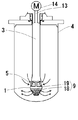
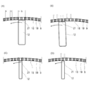
- This stirrer includes a processing unit 1 disposed in a fluid to be processed that is scheduled for processing such as emulsification, dispersion, or mixing, and a rotor 2 disposed in the processing unit 1.
- the processing unit 1 is a hollow housing, and is supported by the support tube 3 so as to be disposed in the storage container 4 for storing the fluid to be processed or the flow path of the fluid to be processed.
- the processing unit 1 is provided at the tip of the support tube 3 and is inserted from the upper part of the storage container 4 to the inside downward.
- the present invention is not limited to this example.
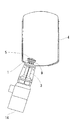
- FIG. As shown, even if the processing unit 1 is supported by the support tube 3 so as to protrude upward from the bottom surface of the storage container 4, it can be implemented.
- the processing unit 1 includes a suction chamber 6 having a suction port 5 for sucking a fluid to be processed from the outside to the inside, and a stirring chamber 7 connected to the suction chamber 6.
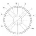
- the outer periphery of the stirring chamber 7 is defined by a screen 9 having a plurality of slits 18.
- the screen 9 is described as being composed of a slit 18 that is a space and a screen member 19 that is an actual member positioned between the slits 18. Therefore, the screen 9 means the whole including the slits 18 formed in the plurality of screen members 19, and the screen member 19 is a single member that exists between the adjacent slits 18. means.
- the suction chamber 6 and the stirring chamber 7 are partitioned by a partition wall 10 and are conducted through an introduction opening 11 provided in the partition wall 10.
- the suction chamber 6 and the partition wall 10 are not essential.
- the entire upper end of the stirring chamber 7 becomes an opening for introduction without providing the suction chamber 6, and the fluid to be processed in the container 4 May be introduced directly into the stirring chamber 7, or may constitute one space in which the suction chamber 6 and the stirring chamber 7 are not partitioned without providing the partition wall 10.
- the rotor 2 is a rotating body including a plurality of blades 12 in the circumferential direction, and rotates while maintaining a minute clearance between the blades 12 and the screen 9.
- Various rotation drive structures can be adopted as the structure for rotating the rotor 2.
- the rotor 2 is provided at the tip of the rotating shaft 13 and is rotatably accommodated in the stirring chamber 7. More specifically, the rotary shaft 13 is inserted into the support tube 3 and further disposed so as to reach the stirring chamber 7 through the suction chamber 6 and the opening 11 of the partition wall 10, and its tip (lower end in the figure).
- a rotor 2 is attached to the main body.
- the rear end of the rotary shaft 13 is connected to a rotary drive device such as a motor 14. It is preferable to use a motor 14 having a control system such as numerical control or one that is placed under the control of a computer.
- This stirrer is emulsified, dispersed or mixed by the shearing force applied to the fluid to be treated existing between the rotating blades 12 passing through the inner wall surface of the screen member 19 as the rotor 2 rotates. Is made.
- the kinetic energy is given to the fluid to be treated by the rotation of the rotor 2, and the fluid to be treated passes through the slit 18 to be further accelerated to form an intermittent jet flow. It flows out to the outside. Due to this intermittent jet flow, a liquid-liquid shearing force is generated at the velocity interface, and emulsification, dispersion, or mixing is performed.
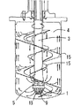
- the screen 9 has a cylindrical shape with a circular cross section. It is desirable that the diameter of the screen 9 gradually decreases as the screen 9 moves away from the introduction opening 11 (in the example of FIG. 2, downward), for example, like a conical surface shape. In the case of a constant diameter in the axial direction, the discharge amount from the slit 18 is large near the introduction opening 11 (upward in FIG. 2), and conversely, the discharge amount decreases farther away (lower in FIG. 2). ). As a result, cavitation that cannot be controlled may occur, which may lead to mechanical failure.
- the slit 18 is linearly extended in the axial direction of the rotating shaft 13 (up and down in the example in the figure), it may be curved and extended.
- the shape of the slit 18 is not necessarily an elongated space, and may be a polygon, a circle, an ellipse, or the like.
- a plurality of slits 18 are formed at equal intervals.
- the slits 18 can be formed at different intervals, and this does not hinder the provision of slits 18 of a plurality of types and sizes.
- the slit 18 can be implemented by appropriately changing the lead angle.
- the lead angle formed by the plane perpendicular to the rotation shaft 13 and the direction in which the slit 18 extends is a linear shape extending in the vertical direction of 90 degrees, and a spiral shape having a predetermined lead angle. A thing etc. which curve and extend in the up-down direction may be used.
- the blades 12 of the rotor 2 can extend linearly from the center of the rotor 2 in a straight line with a certain width in a cross section (a cross section perpendicular to the axial direction of the rotary shaft 13), and as it goes outward.
- the width may be gradually increased, or may be extended outward while being curved.
- the lead angle of the tip portion 21 of these blades 12 can be changed as appropriate.
- the lead angle formed by the plane orthogonal to the rotation shaft 13 and the direction in which the tip end portion 21 extends is linearly extending in the vertical direction of 90 degrees, and the spiral shape having a predetermined lead angle, etc. Further, it may be curved and extended in the vertical direction.
- each of these constituent members is such that the tip end portion of the blade 12 and the slit 18 are provided with a matching region in the same position where they overlap each other in the length direction of the slit 18.
- the fluid to be treated can be sheared between the blades 12 and the screen member 19 in the coincidence region by the rotation of the rotor 2 and passes through the slit 18 as the blades 12 rotate.
- Kinetic energy can be given to the fluid so that an intermittent jet flow is generated.
- the clearance between the screen 9 and the blade 12 can be appropriately changed within the range in which the shearing and the intermittent jet flow are generated, but it is generally preferably about 0.2 to 4.0 mm.
- this clearance can be easily achieved by allowing at least one of the stirring chamber 7 and the rotor 2 to move in the axial direction when a screen 9 having a tapered shape as shown in FIG. 2 is used. Can be adjusted.
- FIG.4 and FIG.5 is also employable.
- a separate stirring device is disposed in the storage container 4 in order to make the entire fluid to be processed in the storage container 4 uniform.
- a stirring blade 15 for stirring the entire inside of the container 4 can be provided so as to rotate in the same body as the stirring chamber 7.
- the stirring blade 15 and the stirring chamber 7 including the screen 9 are rotated together.
- the rotation direction of the stirring blade 15 and the stirring chamber 7 may be the same as the rotation direction of the rotor 2 or may be the opposite direction. That is, the rotation of the stirring chamber 7 including the screen 9 is lower than the rotation of the rotor 2 (specifically, the peripheral speed of the screen rotation is about 0.02 to 0.5 m / s).
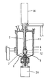
- the stirring chamber 7 can be rotated with respect to the support tube 3, and the rotation shaft of the second motor 20 is connected to the tip of the stirring chamber 7, so that the screen 9 can be rotated at high speed. It is what.
- the rotation direction of the screen 9 is rotated in the direction opposite to the rotation direction of the rotor 2 disposed inside the stirring chamber 7. As a result, the relative rotational speed between the screen 9 and the rotor 2 increases.
- the present invention is applied as follows.
- a shearing force between a liquid and a liquid is generated at a velocity interface by an intermittent jet flow, whereby emulsification, dispersion or mixing is performed.
- the rotor 2 and the screen 9 shown in FIGS. 6A and 6B and FIG. 7 can be used.
- the matching region where the shearing action is exerted on the screen 9 that is, the tip portion 21 of the blade 12 and the slit 18 of the screen 9 are arranged in the length direction of the slit 18. In the same region overlapping each other), both the following first condition and second condition are satisfied.
- the stirrer according to the present invention satisfies both the first condition and the second condition in the coincidence region.
- the axial position of the rotating shaft of the rotor 2 may be any position as long as it is in the coincidence region, but at least at the position where the axial position of the rotating shaft 13 is the maximum inner diameter of the screen 9, It is preferable to satisfy both conditions of the second condition.
- the shear force between the liquid and the liquid can be increased at the speed interface, and extremely fine such as nano-dispersion or nano-emulsification. It has been found that the invention is extremely effective in achieving dispersion and emulsification, and the invention has been completed.
- the intermittent jet flow is generated by the rotation of the blade 12. More specifically, the pressure of the fluid to be processed increases on the front side in the rotation direction of the blade 12. . As a result, the fluid to be treated is discharged as an intermittent jet flow from the slit 18 located on the front side of the blade 12. On the other hand, on the rear surface side in the rotation direction of the blades 12, the fluid to be treated is sucked from the slit 18 located on the rear surface side due to the pressure of the fluid to be treated being reduced.
- the fluid to be treated since the width of the tip 21 of the blade 12 is wide, the fluid to be treated remains stationary during discharge / suction. A period occurs. As a result, the fluid to be treated follows the change in opening and closing of the slit 18 by the blades 12, and the relative speed difference at the interface of the forward and reverse flow (discharge and suction) of the fluid to be treated increases. The shear force generated between the fluids to be treated can be increased. Conditions for realizing this well are the first condition and the second condition.
- the tip portion 21 of the blade 12 and the slit 18 include at least a coincidence region at the same position where they overlap each other in the length direction of the slit 18.
- the length of the blade 12 is set to be equal to or longer than the length of the slit 18, and the blade 12 is in the same position where it overlaps the slit 18 in the entire length of the slit 18, but the length of the blade 12 is the length of the slit 18. It can also be carried out with a shorter length.
- the relationship in the coincidence region means unless otherwise specified.
- the screen 9 can be implemented even when the diameter of the taper shape is changed.
- the maximum inner diameter means the maximum inner diameter of the screen 9 in the matching region.
- the slit 18 may extend in parallel to the axial direction of the rotation axis of the rotor 2 or may have an angle with respect to the axial direction, such as a spiral extension.
- the circumferential width (s) of the slit 18 is the circumferential direction of the screen 9 in the coincidence region (in other words, the axial direction of the rotating shaft of the rotor 2).
- the axial position of the rotating shaft of the rotor 2 may be any position as long as it is in the coincidence region, but at least the axial position of the rotating shaft 13 is a position where the maximum inner diameter of the screen 9 is obtained.
- the circumferential width (s) of the slit 18 is preferably 0.2 to 4.0 mm, and more preferably 0.5 to 2.0 mm. However, the width (s) is appropriately changed on condition that an intermittent jet flow is generated. Can be implemented.
- the circumferential width (t) of the screen member 19 (in other words, the circumferential distance between adjacent slits 18) can be changed as appropriate, but the circumferential width (s) of the slit 18 (s ) Is preferably 0.1 to 10 times, more preferably about 0.5 to 2 times. If the circumferential width (t) of the screen member 19 is too large, the number of shears decreases and the amount of processing decreases, and if it is too small, the slit 18 is substantially the same. The mechanical strength may be significantly reduced.
- the rotor 2 is a rotating body having a plurality of blades 12 as described above. In the coincidence region, the tip portion 21 of the blade 12 satisfies the conditions 1 and 2, thereby exhibiting the effects of the present invention. If the width of the tip portion 21 of the blade 12 is too large, the volume of the space between the blade 12 and the blade 12 becomes too small, which may cause a problem such as reducing the processing amount. From this point, the rotor 2 changes in accordance with the inner diameter of the screen 9, but the rotor 2 has a blade 12 on a plane orthogonal to the rotary shaft 13 in a region defined by the outer peripheral surface of the rotary shaft 13 and the inner peripheral surface of the screen 9.
- the sum of the cross-sectional areas of the blades 12 in the plane orthogonal to the rotation axis 13 is Y in the following specific formulas 1 and 2, and the screen 9 in the plane perpendicular to the rotation axis 13 in the coincidence area.
- the sectional area of the inner space is Z in the following specific formulas 1 and 2, it is preferable that Y and Z satisfy the following specific formula 2.
- X in the specific formula 1 refers to an area of a cross section orthogonal to the rotation shaft 13 in a region defined by the outer peripheral surface of the rotary shaft 13 and the inner peripheral surface of the screen 9 in the matching region.
- XY Z (Specific Formula 1) Y ⁇ Z (specific formula 2) It is preferable that the specific formula 2 is satisfied in at least one of the plurality of cross sections in the coincidence region, and it is more preferable that the specific formula 2 is satisfied in all cross sections. Then, as shown in FIG. 2, the screen 9 whose diameter gradually decreases with increasing distance from the introduction opening 11 (downward in the example of FIG. 2), and the axial direction of the plane orthogonal to the rotation axis 13. When the position is a position that is the maximum inner diameter of the screen 9 in the coincidence region, Y / Z is preferably 0.2 or more and less than 1, and Y / Z is more preferably 0.34 or more and 0.6 or less.
- Y / Z is more preferably 0.34 or more and 0.5 or less.
- Y / Z can be calculated based on the diameter of the rotating shaft 13, the diameter of the blade 12, the width of the blade 12 in the rotation direction, the inner diameter of the screen 9, and the like.
- the numerical conditions of the screen 9, the slit 18, and the rotor 2 that can be applied to the conditions 1 and 2 of the present invention and are suitable for mass production with the current technical capabilities are as follows.
- Maximum inner diameter of the screen 9 30 to 500 mm (however, the maximum diameter in the matching area)
- Number of rotations of screen 9 15 to 390 times / s
- Number of slits 18 20 to 500
- Maximum outer diameter of rotor 2 30 to 500 mm
- Number of rotations of rotor 2 15 to 390 times / s
- these numerical conditions are merely examples.
- the present invention does not exclude the use of conditions other than the above-mentioned conditions as technology advances in the future such as rotation control.
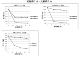
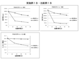
- Example 1 and Comparative Example 1 As Example 1 (ie, Example 1A and Example 1B) and Comparative Example 1 (ie, Comparative Example 1A and Comparative Example 1B), the stirrer according to the first embodiment of the present invention (FIGS. 1 and 2) Were used to conduct treatment tests (Example 1A / Comparative Example 1A and Example 1B / Comparative Example 1B) on two types of fluids to be treated.
- Aqualon KH-10 is a surfactant manufactured by Daiichi Kogyo Seiyaku.
- the pre-mixed product in the external container (1 L tall beaker equipped with a stirrer) is introduced into the processing container (350 cc) having a stirrer by the pump in the test apparatus shown in FIG.
- the processing container 350 cc having a stirrer by the pump in the test apparatus shown in FIG.
- the fluid to be processed is discharged from the discharge port and circulating between the processing container and the external container,
- the rotor of the stirrer was rotated at 20000 rpm and discharged from the screen, and the fine particle treatment was performed under the conditions shown in Table 1. In either example, the screen was not rotated.
- the slit width and the width of the screen member described in Table 1 are the slit width and the width of the screen member at a position where the axial position of the surface orthogonal to the rotation axis 13 is the maximum inner diameter of the screen 9 in the coincidence region. .
- Example 1 both the above-described Condition 1 and Condition 2 were satisfied, whereas in Comparative Example 1, both Condition 1 and Condition 2 were not satisfied.
- the variation coefficient of the particle diameter serves as an index representing the degree of uniformity of the obtained particles, and the coefficient of variation (CV) is calculated from the average particle diameter (D50) and the standard deviation in the particle diameter distribution of the particles.
- Example 2 Next, according to Example 2, it was confirmed whether the particle diameter of the rotor and the screen having a larger diameter than that of Example 1 was significantly reduced according to the processing time.
- the processing conditions are shown in Table 1, and the test results are shown in FIG.
- the processing apparatus is substantially the same as in Example 1 except that the entire size is increased according to the processing amount (external container: a 300 L tank equipped with a stirring device, a processing container (8.5 L)). did.
- pulverized component dextrin
- dispersion medium vegetable oil were used.
- Even in the second embodiment as apparent from Table 1, both the above-described condition 1 and condition 2 are satisfied.
Landscapes
- Chemical & Material Sciences (AREA)
- Chemical Kinetics & Catalysis (AREA)
- Dispersion Chemistry (AREA)
- Mixers Of The Rotary Stirring Type (AREA)
Priority Applications (5)
| Application Number | Priority Date | Filing Date | Title |
|---|---|---|---|
| EP16768798.7A EP3275534B1 (en) | 2015-03-24 | 2016-03-23 | Stirrer |
| KR1020177025071A KR102526910B1 (ko) | 2015-03-24 | 2016-03-23 | 교반기 |
| CN201680014471.5A CN107427794B (zh) | 2015-03-24 | 2016-03-23 | 搅拌机 |
| US15/557,016 US10478790B2 (en) | 2015-03-24 | 2016-03-23 | Stirrer producing intermittent jet flow |
| JP2017508377A JPWO2016152895A1 (ja) | 2015-03-24 | 2016-03-23 | 攪拌機 |
Applications Claiming Priority (2)
| Application Number | Priority Date | Filing Date | Title |
|---|---|---|---|
| JP2015-061360 | 2015-03-24 | ||
| JP2015061360 | 2015-03-24 |
Publications (1)
| Publication Number | Publication Date |
|---|---|
| WO2016152895A1 true WO2016152895A1 (ja) | 2016-09-29 |
Family
ID=56978205
Family Applications (1)
| Application Number | Title | Priority Date | Filing Date |
|---|---|---|---|
| PCT/JP2016/059122 Ceased WO2016152895A1 (ja) | 2015-03-24 | 2016-03-23 | 攪拌機 |
Country Status (6)
| Country | Link |
|---|---|
| US (1) | US10478790B2 (https=) |
| EP (1) | EP3275534B1 (https=) |
| JP (2) | JPWO2016152895A1 (https=) |
| KR (1) | KR102526910B1 (https=) |
| CN (1) | CN107427794B (https=) |
| WO (1) | WO2016152895A1 (https=) |
Cited By (4)
| Publication number | Priority date | Publication date | Assignee | Title |
|---|---|---|---|---|
| JP6598345B1 (ja) * | 2019-04-15 | 2019-10-30 | エム・テクニック株式会社 | 攪拌機 |
| JP6601862B1 (ja) * | 2019-04-15 | 2019-11-06 | エム・テクニック株式会社 | 攪拌機 |
| JP2020006362A (ja) * | 2018-07-02 | 2020-01-16 | 株式会社田定工作所 | 撹拌用回転体及び撹拌装置 |
| JP6650162B1 (ja) * | 2019-04-15 | 2020-02-19 | エム・テクニック株式会社 | 攪拌機 |
Families Citing this family (2)
| Publication number | Priority date | Publication date | Assignee | Title |
|---|---|---|---|---|
| WO2016152895A1 (ja) * | 2015-03-24 | 2016-09-29 | エム・テクニック株式会社 | 攪拌機 |
| WO2020124263A1 (en) * | 2018-12-21 | 2020-06-25 | Nanorial Technologies Ltd. | Apparatus, methods, and systems for mixing, dispersing substances |
Citations (2)
| Publication number | Priority date | Publication date | Assignee | Title |
|---|---|---|---|---|
| FR2679789A1 (fr) * | 1991-07-31 | 1993-02-05 | Ouest Enrobes Modernes | Melangeur-disperseur a pulsations pour la preparation de produits thermoplastiques, en particulier de produits bitumineux. |
| JPH0796167A (ja) * | 1993-09-27 | 1995-04-11 | Matsumoto Yushi Seiyaku Co Ltd | マイクロカプセルの製法 |
Family Cites Families (26)
| Publication number | Priority date | Publication date | Assignee | Title |
|---|---|---|---|---|
| DE1048465B (de) | 1959-01-08 | Fritz Eichenauer Bernd Eichenauer und Erika Eichtnauer Kandel (Pfalz) | Vorrichtung zum Femaufspal ten von Glimmer durch Naßzerkleinerung | |
| US1048465A (en) * | 1912-12-24 | Cornelius J Nolan | Glass-blowing machine. | |
| US755913A (en) * | 1901-07-06 | 1904-03-29 | Donald Barns Morison | Mortar-box for stamp-mills. |
| US1140440A (en) * | 1914-02-17 | 1915-05-25 | Romulus C Chevalier | Hoist. |
| US2628081A (en) * | 1948-11-12 | 1953-02-10 | T J Laird Equipment Corp | Mixer |
| GB755913A (en) * | 1950-08-19 | 1956-08-29 | Equipments Ind Et Laitiers S B | Machines for the production of finely divided mixtures |
| DE1140440B (de) * | 1957-11-06 | 1962-11-29 | Forsch Inst Professor Ing Chem | Zerkleinerungs-, Ruehr- und Mischvorrichtung |
| US3195867A (en) * | 1962-01-23 | 1965-07-20 | Liberty Nat Bank And Trust Com | Homogenizing apparatus |
| JPS5147091B2 (https=) | 1971-09-30 | 1976-12-13 | ||
| US4347004A (en) * | 1979-06-13 | 1982-08-31 | Unishear Mixers Limited | Mixing apparatus |
| JPS6061028A (ja) * | 1983-09-14 | 1985-04-08 | Kikuji Okada | 流体混合装置 |
| JP3123556B2 (ja) | 1990-06-30 | 2001-01-15 | エム・テクニック株式会社 | 攪はん機 |
| JP2813673B2 (ja) | 1990-09-01 | 1998-10-22 | エム・テクニック株式会社 | 攪拌機 |
| JP2002091072A (ja) | 2000-09-13 | 2002-03-27 | Canon Inc | トナーの製造方法 |
| JP4909693B2 (ja) * | 2006-07-24 | 2012-04-04 | 相川鉄工株式会社 | スクリーン装置 |
| TWI542407B (zh) * | 2010-08-19 | 2016-07-21 | Meiji Co Ltd | Performance Evaluation Method and Amplification Method of Micro - granulation Device |
| JP5897466B2 (ja) * | 2010-08-19 | 2016-03-30 | 株式会社明治 | 微粒化装置 |
| WO2012023217A1 (ja) * | 2010-08-19 | 2012-02-23 | 株式会社明治 | 微粒化装置及びその性能評価方法とスケールアップ方法 |
| WO2012128273A1 (ja) * | 2011-03-23 | 2012-09-27 | エム・テクニック株式会社 | 微粒子の製造方法 |
| TWI604885B (zh) * | 2011-08-19 | 2017-11-11 | 明治股份有限公司 | Microprocessing equipment |
| KR101954110B1 (ko) * | 2012-07-13 | 2019-03-05 | 엠. 테크닉 가부시키가이샤 | 교반기 |
| EP2939734B1 (en) * | 2012-12-25 | 2024-04-03 | M Technique Co., Ltd. | Stirring device and method |
| US10137420B2 (en) * | 2014-02-27 | 2018-11-27 | Schlumberger Technology Corporation | Mixing apparatus with stator and method |
| KR102440016B1 (ko) * | 2014-07-14 | 2022-09-05 | 엠. 테크닉 가부시키가이샤 | 단결정 산화아연 나노 입자의 제조 방법 |
| WO2016152895A1 (ja) * | 2015-03-24 | 2016-09-29 | エム・テクニック株式会社 | 攪拌機 |
| JP6830661B2 (ja) * | 2015-06-30 | 2021-02-17 | エム・テクニック株式会社 | 有機化合物の製造方法 |
-
2016
- 2016-03-23 WO PCT/JP2016/059122 patent/WO2016152895A1/ja not_active Ceased
- 2016-03-23 CN CN201680014471.5A patent/CN107427794B/zh active Active
- 2016-03-23 JP JP2017508377A patent/JPWO2016152895A1/ja active Pending
- 2016-03-23 EP EP16768798.7A patent/EP3275534B1/en active Active
- 2016-03-23 KR KR1020177025071A patent/KR102526910B1/ko active Active
- 2016-03-23 US US15/557,016 patent/US10478790B2/en active Active
-
2021
- 2021-10-05 JP JP2021163810A patent/JP7212965B2/ja active Active
Patent Citations (2)
| Publication number | Priority date | Publication date | Assignee | Title |
|---|---|---|---|---|
| FR2679789A1 (fr) * | 1991-07-31 | 1993-02-05 | Ouest Enrobes Modernes | Melangeur-disperseur a pulsations pour la preparation de produits thermoplastiques, en particulier de produits bitumineux. |
| JPH0796167A (ja) * | 1993-09-27 | 1995-04-11 | Matsumoto Yushi Seiyaku Co Ltd | マイクロカプセルの製法 |
Non-Patent Citations (1)
| Title |
|---|
| See also references of EP3275534A4 * |
Cited By (17)
| Publication number | Priority date | Publication date | Assignee | Title |
|---|---|---|---|---|
| JP2020006362A (ja) * | 2018-07-02 | 2020-01-16 | 株式会社田定工作所 | 撹拌用回転体及び撹拌装置 |
| JP7240652B2 (ja) | 2018-07-02 | 2023-03-16 | 株式会社田定工作所 | 撹拌用回転体及び撹拌装置 |
| WO2020213048A1 (ja) | 2019-04-15 | 2020-10-22 | エム・テクニック株式会社 | 攪拌機 |
| KR20210150950A (ko) | 2019-04-15 | 2021-12-13 | 엠. 테크닉 가부시키가이샤 | 교반기 |
| JP6598345B1 (ja) * | 2019-04-15 | 2019-10-30 | エム・テクニック株式会社 | 攪拌機 |
| WO2020213184A1 (ja) | 2019-04-15 | 2020-10-22 | エム・テクニック株式会社 | 攪拌機 |
| WO2020213177A1 (ja) | 2019-04-15 | 2020-10-22 | エム・テクニック株式会社 | 攪拌機 |
| KR20210151059A (ko) | 2019-04-15 | 2021-12-13 | 엠. 테크닉 가부시키가이샤 | 교반기 |
| KR20210150949A (ko) | 2019-04-15 | 2021-12-13 | 엠. 테크닉 가부시키가이샤 | 교반기 |
| JP6650162B1 (ja) * | 2019-04-15 | 2020-02-19 | エム・テクニック株式会社 | 攪拌機 |
| US11241661B2 (en) | 2019-04-15 | 2022-02-08 | M. Technique Co., Ltd. | Stirrer |
| EP3957391A4 (en) * | 2019-04-15 | 2022-12-21 | M. Technique Co., Ltd. | STIRRER |
| JP6601862B1 (ja) * | 2019-04-15 | 2019-11-06 | エム・テクニック株式会社 | 攪拌機 |
| US11628412B2 (en) | 2019-04-15 | 2023-04-18 | M. Technique Co., Ltd. | Stirrer |
| KR102666285B1 (ko) * | 2019-04-15 | 2024-05-16 | 엠. 테크닉 가부시키가이샤 | 교반기 |
| KR102666286B1 (ko) * | 2019-04-15 | 2024-05-16 | 엠. 테크닉 가부시키가이샤 | 교반기 |
| KR102703317B1 (ko) * | 2019-04-15 | 2024-09-05 | 엠. 테크닉 가부시키가이샤 | 교반기 |
Also Published As
| Publication number | Publication date |
|---|---|
| EP3275534A4 (en) | 2018-11-14 |
| EP3275534B1 (en) | 2020-04-22 |
| US20180056255A1 (en) | 2018-03-01 |
| KR20170129723A (ko) | 2017-11-27 |
| JP2022000306A (ja) | 2022-01-04 |
| EP3275534A1 (en) | 2018-01-31 |
| JP7212965B2 (ja) | 2023-01-26 |
| KR102526910B1 (ko) | 2023-04-28 |
| CN107427794B (zh) | 2021-05-07 |
| JPWO2016152895A1 (ja) | 2018-01-18 |
| US10478790B2 (en) | 2019-11-19 |
| CN107427794A (zh) | 2017-12-01 |
Similar Documents
| Publication | Publication Date | Title |
|---|---|---|
| JP5147091B1 (ja) | 攪拌機 | |
| JP7212965B2 (ja) | 攪拌機 | |
| JP6601862B1 (ja) | 攪拌機 | |
| JP6650162B1 (ja) | 攪拌機 | |
| JP6598345B1 (ja) | 攪拌機 | |
| JP6069707B2 (ja) | 流体処理装置及び流体処理方法 | |
| KR102649462B1 (ko) | 교반기 |
Legal Events
| Date | Code | Title | Description |
|---|---|---|---|
| 121 | Ep: the epo has been informed by wipo that ep was designated in this application |
Ref document number: 16768798 Country of ref document: EP Kind code of ref document: A1 |
|
| ENP | Entry into the national phase |
Ref document number: 2017508377 Country of ref document: JP Kind code of ref document: A |
|
| ENP | Entry into the national phase |
Ref document number: 20177025071 Country of ref document: KR Kind code of ref document: A |
|
| WWE | Wipo information: entry into national phase |
Ref document number: 15557016 Country of ref document: US |
|
| REEP | Request for entry into the european phase |
Ref document number: 2016768798 Country of ref document: EP |
|
| NENP | Non-entry into the national phase |
Ref country code: DE |