WO2016140329A1 - 絶縁性樹脂組成物、樹脂シート、樹脂フィルム及び絶縁物 - Google Patents
絶縁性樹脂組成物、樹脂シート、樹脂フィルム及び絶縁物 Download PDFInfo
- Publication number
- WO2016140329A1 WO2016140329A1 PCT/JP2016/056669 JP2016056669W WO2016140329A1 WO 2016140329 A1 WO2016140329 A1 WO 2016140329A1 JP 2016056669 W JP2016056669 W JP 2016056669W WO 2016140329 A1 WO2016140329 A1 WO 2016140329A1
- Authority
- WO
- WIPO (PCT)
- Prior art keywords
- compound
- layered inorganic
- inorganic compound
- specific
- resin composition
- Prior art date
- Legal status (The legal status is an assumption and is not a legal conclusion. Google has not performed a legal analysis and makes no representation as to the accuracy of the status listed.)
- Ceased
Links
Images




Classifications
-
- C—CHEMISTRY; METALLURGY
- C08—ORGANIC MACROMOLECULAR COMPOUNDS; THEIR PREPARATION OR CHEMICAL WORKING-UP; COMPOSITIONS BASED THEREON
- C08J—WORKING-UP; GENERAL PROCESSES OF COMPOUNDING; AFTER-TREATMENT NOT COVERED BY SUBCLASSES C08B, C08C, C08F, C08G or C08H
- C08J5/00—Manufacture of articles or shaped materials containing macromolecular substances
- C08J5/18—Manufacture of films or sheets
-
- C—CHEMISTRY; METALLURGY
- C08—ORGANIC MACROMOLECULAR COMPOUNDS; THEIR PREPARATION OR CHEMICAL WORKING-UP; COMPOSITIONS BASED THEREON
- C08K—Use of inorganic or non-macromolecular organic substances as compounding ingredients
- C08K3/00—Use of inorganic substances as compounding ingredients
- C08K3/34—Silicon-containing compounds
-
- C—CHEMISTRY; METALLURGY
- C08—ORGANIC MACROMOLECULAR COMPOUNDS; THEIR PREPARATION OR CHEMICAL WORKING-UP; COMPOSITIONS BASED THEREON
- C08K—Use of inorganic or non-macromolecular organic substances as compounding ingredients
- C08K9/00—Use of pretreated ingredients
- C08K9/04—Ingredients treated with organic substances
-
- C—CHEMISTRY; METALLURGY
- C08—ORGANIC MACROMOLECULAR COMPOUNDS; THEIR PREPARATION OR CHEMICAL WORKING-UP; COMPOSITIONS BASED THEREON
- C08L—COMPOSITIONS OF MACROMOLECULAR COMPOUNDS
- C08L101/00—Compositions of unspecified macromolecular compounds
- C08L101/12—Compositions of unspecified macromolecular compounds characterised by physical features, e.g. anisotropy, viscosity or electrical conductivity
-
- H—ELECTRICITY
- H01—ELECTRIC ELEMENTS
- H01B—CABLES; CONDUCTORS; INSULATORS; SELECTION OF MATERIALS FOR THEIR CONDUCTIVE, INSULATING OR DIELECTRIC PROPERTIES
- H01B3/00—Insulators or insulating bodies characterised by the insulating materials; Selection of materials for their insulating or dielectric properties
Definitions
- the present invention relates to an insulating resin composition, a resin sheet, a resin film, and an insulator.
- Insulating members of various electric and electronic devices are often made of insulating resin materials based on resin from the viewpoints of insulation, chemical stability, mechanical strength, heat resistance, cost, etc. .
- Japanese Patent Application Laid-Open No. 2008-75069 discloses that an insulating resin is filled with an inorganic compound such as silica, alumina, or a smectite clay compound.
- JP-A-9-208745 and JP-A-2008-7753 by combining a layered inorganic compound such as mica and a thermoplastic resin such as polypropylene or polyamide, the insulation and resistance of the composite material are obtained. Attempts have been made to improve various performances such as voltage and heat resistance. In these prior arts, when the thermoplastic resin and the layered inorganic compound are dispersed, a method of melt kneading the layered inorganic compound into the thermoplastic resin is used.
- thermoplastic resin such as polypropylene
- heat is applied to the thermoplastic resin such as polypropylene.
- thermoplastic resin such as polypropylene.
- unintended changes, fluctuations, or non-uniformity of the kneading conditions may impair the uniformity or reproducibility of the dispersion of the layered inorganic compound in the thermoplastic resin, and thus the desired material properties for the composite material. May be damaged.
- layered inorganic compounds inherently contain alkali metals such as sodium and potassium, which have hydrophilicity between layers, and have hydroxyl groups on the crystal surface, and thus have affinity for polar solvents such as water, but organic Low affinity for organic substances such as solvents and resins. Therefore, in the kneading with the resin, the layered inorganic compound is agglomerated and voids accompanying the aggregation occur, making it difficult to uniformly disperse the layered inorganic compound in the resin, workability, insulation, voltage resistance There is a problem that various performances such as heat resistance are deteriorated.
- the insulating resin material is required to have high reliability, in order to improve various performances such as better insulation, high thermal conductivity, voltage resistance, etc., a certain amount or more of the layered inorganic compound is required. Filling is necessary. However, when the filling rate is increased, the resin does not enter the space around the layered inorganic compound, and voids are easily formed. In addition to the deterioration of various performances of the insulating resin material, there is a problem that the manufacturing cost increases. . In order to solve this problem, it is effective to increase the aspect ratio (aspect ratio) of the layered inorganic compound, that is, to increase the specific surface area.
- JP-A-9-87096 reports that the mechanical properties of a composite material of a smectite clay compound, which is a layered inorganic compound having an increased aspect ratio, and resin are improved.
- a layered inorganic compound Like the smectite clay compound, mica, a layered inorganic compound, is considered to have a higher effect of improving insulation, voltage resistance, heat resistance, etc. of the material combined with the resin as the aspect ratio is larger. Therefore, in order to realize these problems, development of a layered inorganic compound peeling technique (nanosheet forming technique) is required.
- the layers of the layered inorganic compound are formed by relatively weak bonds such as van der Waals force and electrostatic interaction.
- This van der Waals force can be generally expressed by the dispersion force of the Lennard-Jones potential shown in equation (1) (the sixth-order term in the equation), and is known to be inversely proportional to the sixth power of the distance r. ing.
- the electrostatic interaction can be expressed by the equation (2), and is known to be inversely proportional to the distance r.
- U (r) is the potential energy of an arbitrary pair of molecules
- ⁇ and ⁇ are the fitting parameters specific to the molecule
- q + and q ⁇ are the charge amount
- ⁇ r is the relative dielectric constant of the medium
- ⁇ 0 is the vacuum Dielectric constant
- r refers to distance.
- the present inventors have conducted extensive research on a method for intercalating an organic compound between layers of a layered inorganic compound (intercalation), and have made a composite of the layered inorganic compound and the organic compound.
- the body and its manufacturing method that is, organic processing
- the exfoliated layered inorganic compound, and its manufacturing method are being studied.
- Intercalation is a phenomenon in which atoms, molecules, etc. enter between layers of a layered inorganic compound. Since there is no change in crystal structure before and after intercalation, intercalation into clay compounds such as smectite as a pretreatment for exfoliation of the layered inorganic compound and an operation to improve the affinity between the resin and the layered inorganic compound Is used.
- the layered inorganic compound organically treated by intercalation shows affinity for a resin such as a nylon resin.
- JP-A-63-215775 a layered inorganic compound and an organic compound such as a monomer are directly added to a matrix resin and kneaded and polymerized to uniformly disperse the layered inorganic compound in the resin.
- Japanese Patent Application Laid-Open No. 2004-169030 an attempt is made to obtain a layered inorganic compound obtained by dispersing and treating an organically treated layered inorganic compound under strong conditions such as ultrasonic irradiation.
- JP 2009-191239 A describes that a resin composition with improved partial discharge resistance can be obtained.
- JP 2012-158622 A discloses that after laminating a layered inorganic compound with water or an aqueous mixed solvent, the layered inorganic compound functionalized with a silane coupling agent is kneaded with a resin. A method for producing a resin composition for high voltage equipment with improved insulation performance is described.
- International Publication No. 2006/22431 is an organic-inorganic composite obtained by treating non-swellable mica having a large primary particle size with a concentrated solution of a positively charged organic compound, and the organic-inorganic composite is well dispersed.
- the present invention relates to a polymer composite material.
- JP-A-63-215775 uses a polymerization reaction, it is necessary to consider the reaction method according to the type and amount of the monomer of the base resin and the organic compound to be intercalated, and the production cost is reduced. There is a problem that it increases.
- the method disclosed in Japanese Patent Application Laid-Open No. 2004-169030 has a problem in that the mica is pulverized, not peeled, by ultrasonic waves, and the length of the mica in the longitudinal direction (a-axis) is reduced, thereby reducing the aspect ratio. .
- the resin composition is produced by kneading with the resin as it is, a large amount of residual organic compound and various metal ions are present in the finally obtained resin composition. Therefore, it is considered that the effect of improving the insulating properties of the resin composition is small.
- JP2012-158622A cannot be applied to the production of a resin composition due to the problem of compatibility with a hydrophobic resin and the inability to process at a temperature higher than the boiling point of water. It is done.
- the layered inorganic compound is exfoliated only in the complexing process with the polymer, that is, the kneading process. Therefore, the compounding method and compounding conditions for obtaining a sufficient effect are limited.
- an object of the present invention is to provide an insulating resin composition having a high withstand voltage and a resin sheet, a resin film and an insulator using the same.
- An insulating resin composition comprising a thermoplastic resin and an inorganic filler, wherein at least a part of the inorganic filler is a peeled layered inorganic compound having an average particle thickness in the c-axis direction of 1 nm to 80 nm. object.
- ⁇ 2> The insulating resin composition according to ⁇ 1>, wherein the content of the exfoliated layered inorganic compound is 1% by volume to 10% by volume.
- ⁇ 3> A resin sheet formed by molding the insulating resin composition according to ⁇ 1> or ⁇ 2> into a sheet shape.
- ⁇ 4> A resin film obtained by molding the insulating resin composition according to ⁇ 1> or ⁇ 2> into a film shape.
- An insulator which is a molded product of the insulating resin composition according to ⁇ 1> or ⁇ 2>.
- an insulating resin composition having a high withstand voltage and a resin sheet, a resin film and an insulator using the same are provided.
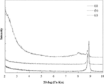
- FIG. 3 is a graph showing the results of XRD measurement of the sample obtained in Example 1. It is the photograph which shows the state which left the dispersion liquid for 2 weeks, (a) shows the case of the dispersion liquid which did not implement peeling processing, (b) shows the case of the dispersion liquid which performed peeling processing.
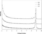
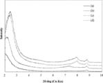
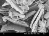
- 6 is a graph showing the results of XRD measurement of a sample obtained in Comparative Example 2. 6 is a graph showing the results of XRD measurement of the sample obtained in Example 5. It is a photograph which shows the SEM image of the mica powder before peeling processing. 2 is a photograph showing an SEM image of the exfoliating compound refluxed for 96 hours in Example 5.
- the upper limit value or the lower limit value described in one numerical range may be replaced with the upper limit value or the lower limit value of another numerical range. Good. Further, in the numerical ranges described in this specification, the upper limit value or the lower limit value of the numerical range may be replaced with the values shown in the examples.
- the content of each component in the composition is the total amount of the plurality of substances present in the composition unless there is a specific indication when there are a plurality of substances corresponding to each component in the composition. means.
- the particle size of each component in the composition is such that when there are a plurality of types of particles corresponding to each component in the composition, unless otherwise specified, the mixture of the plurality of types of particles present in the composition. Mean value.
- the insulating resin composition of the present embodiment contains a thermoplastic resin and an inorganic filler, and at least a part of the inorganic filler is a peeled layered layer having an average particle thickness in the c-axis direction of 1 nm to 80 nm.
- An inorganic compound hereinafter, the layered inorganic compound may be referred to as a “specific release compound”).
- insulating resin compositions containing small anisotropy and spherical silica, alumina, etc. have a short dielectric breakdown path, and the dielectric breakdown voltage of the insulating resin composition is reduced. There was something I had to do.
- inorganic nanoparticles layered inorganic compounds such as nano-sized BN (boron nitride) and mica can be considered.
- nano-sized BN boron nitride
- mica layered inorganic compounds
- the affinity with the thermoplastic resin is poor, voids are likely to be generated inside the insulating resin composition, and the insulating properties may be lowered.
- an insulating resin composition having high insulation reliability is manufactured by using a layered inorganic compound (specific release compound) exfoliated to a specific thickness.
- a layered inorganic compound (specific release compound) exfoliated to a specific thickness is obtained by using a layered inorganic compound (specific release compound) exfoliated to a specific thickness.
- the specific exfoliating compound used in the present embodiment is excellent not only in electrical insulation but also in heat resistance and chemical resistance, and further in cost performance.
- the insulating resin composition of the present embodiment contains at least one thermoplastic resin.
- the thermoplastic resin include polyethylene, polypropylene, polyethylene terephthalate, polybutylene terephthalate, polyvinyl chloride, polyvinylidene chloride, polyvinylidene fluoride, polyacetal, polyphenylene sulfide, polyphenylene ether, polyether ether ketone, polysulfone, and polyether sulfone.
- the content of the thermoplastic resin in the insulating resin composition of the present embodiment is not particularly limited.
- the solid content of the insulating resin composition of the present embodiment can be 50% to 99% by mass, preferably 65% to 99% by mass, and 85% to 99% by mass. More preferably. Formability can be improved more because the content rate of a thermoplastic resin is the said range.
- the solid content of the insulating resin composition means a residue obtained by removing volatile components from the insulating resin composition.
- the insulating resin composition of this embodiment contains an inorganic filler.
- at least a part of the inorganic filler is a specific release compound.
- a method for producing the specific exfoliating compound will be described later.
- the content of the specific release compound (that is, the proportion of the insulating resin composition) is preferably in the range of 1% to 10% by volume, more preferably in the range of 2% to 7% by volume. preferable.
- the content rate of a specific peeling compound is 1 volume% or more, it exists in the tendency for the insulation of the insulating resin composition of this embodiment to improve more.
- the content of the specific exfoliating compound is 10% by volume or less, the moldability of the insulating resin composition of the present embodiment tends to be further improved.
- the inorganic filler other than the specific exfoliating compound is not particularly limited, and compounds well known in the art can be used. Examples thereof include aluminum oxide (alumina), magnesium oxide, silicon oxide, aluminum hydroxide, titanium oxide, zirconium oxide, and calcium carbonate.
- the ratio of the specific exfoliating compound to the inorganic filler is preferably in the range of 5% by mass to 100% by mass, and 20% by mass to 100%.
- the range is more preferably in the range of 50% by mass, and still more preferably in the range of 50% by mass to 100% by mass.
- the average particle size of the specific release compound is preferably 0.1 ⁇ m to 20 ⁇ m, more preferably 0.5 ⁇ m to 10 ⁇ m, and even more preferably 1 ⁇ m to 6 ⁇ m.
- the average particle thickness in the c-axis direction of the specific exfoliating compound is 1 nm to 80 nm, preferably 10 nm to 70 nm, and more preferably 20 nm to 50 nm.
- the average particle thickness in the c-axis direction of the specific exfoliating compound is 1 nm or more, the specific exfoliating compound tends to be difficult to break. If the average particle thickness in the c-axis direction of the specific exfoliating compound is 80 nm or less, the insulation reliability tends to be improved.
- the average particle diameter of particles such as a specific exfoliating compound can be measured by using a laser diffraction / scattering particle size distribution analyzer. After putting the measurement object into the dispersion, it is dispersed with a stirrer or the like. By measuring the particle size distribution of the dispersion, the particle size distribution of the measurement object is measured. Based on the particle size distribution, the average particle size is determined as a particle size corresponding to 50% volume accumulation from the small diameter side.
- the insulating resin composition of this embodiment can further contain an additive as necessary.
- the additive include compatibilizers such as an elastomer, a coupling agent, and a modified thermoplastic resin that can improve the peelability and dispersibility of the specific release compound.
- various additives generally used for resin compositions such as antioxidants, anti-aging agents, stabilizers, flame retardants, and thickeners can be exemplified.
- the content of these additives is not particularly limited as long as the effects of the present invention are not impaired.
- the specific exfoliating compound used in the present embodiment is not particularly limited as long as it is a exfoliated layered inorganic compound having an average particle thickness in the c-axis direction of 1 nm to 80 nm.
- the specific exfoliating compound for example, has a layered structure in which unit crystal layers are stacked on each other, and expands in the c-axis direction in the range of 0.05 to 0.20 by heating for 1 hour at the upper limit of the thermal decomposition temperature.
- a composite of a layered inorganic compound and an organic compound obtained by intercalating an organic compound with a non-swellable layered inorganic compound in which the crystal structure of the unit crystal layer does not change by heating at the upper limit of the thermal decomposition temperature for 1 hour Can be used.
- a composite of a layered inorganic compound and an organic compound may be referred to as a “specific composite”.
- the specific composite for example, has a layered structure in which unit crystal layers are stacked on each other, and expands in the c-axis direction in the range of 0.05 to 0.20 by heating for 1 hour at the upper limit of the thermal decomposition temperature.
- the organic compound is intercalated into the non-swellable layered inorganic compound and the organic compound is inserted between the layers of the non-swellable layered inorganic compound in a dispersion obtained by dispersing the heat-treated non-swellable layered inorganic compound in the medium. And the process of carrying out.
- the inventors of the present invention have made extensive studies to intercalate organic compounds with non-swellable layered inorganic compounds.
- the non-swellable layered inorganic compound is heat-treated within the range of the thermal decomposition temperature of the non-swellable layered inorganic compound, and the non-swellable layered inorganic compound is easily expanded between the layers by expanding in the c-axis direction. It was found that a specific complex can be formed by intercalation.
- the specific composite is useful as a substance in the previous stage when exfoliating the layered inorganic compound.
- non-swellable layered inorganic compound used in the present embodiment examples include mica, kaolinite, and pyrophyllite.
- mica having excellent insulating properties is preferable.
- non-swellable mica examples include muscovite, biotite, paragonite, margarite, clintonite, anandite, chlorite, phlogopite, lepidrite, mascobite, biotite, teniolite, and tetrasilicic mica.
- the non-swellable layered inorganic compound used in the present embodiment expands in the c-axis direction in the range of 0.05 to 0.20 by heating at the upper limit of the thermal decomposition temperature for 1 hour, and the thermal decomposition temperature. It is necessary that the crystal structure of the unit crystal layer does not change by heating at the upper limit of 1 hour.
- the type of mica is not particularly limited and may be a natural product, such as a hydrothermal synthesis method, a melting method, a solid phase method, etc. It may be a composite of The non-swellable layered inorganic compound is a compound in which unit crystal layers are stacked to form a layered structure.
- the degree of expansion of the non-swellable layered inorganic compound in the c-axis direction can be measured with an X-ray diffraction apparatus (X-Ray Diffraction, XRD).
- X-Ray Diffraction X-Ray Diffraction
- Whether or not the crystal structure of the unit crystal layer of the non-swellable layered inorganic compound has been changed by heating for 1 hour at the upper limit of the thermal decomposition temperature is determined by measuring the non-swellable layered inorganic compound before and after heating by XRD. Analysis can be confirmed by measuring changes in the crystal structure.
- the specific complex can be obtained by intercalating an organic compound between layers of a layered inorganic compound.
- the intercalating substance is an organic compound.
- the organic compound used in the present embodiment is not particularly limited in its kind, and is at least one cationic organic compound selected from the group consisting of amine salts, phosphonium salts, imidazolium salts, pyridinium salts, sulfonium salts, and iodonium salts. Is mentioned.
- Examples of amine salts that can be used in the present embodiment include primary to quaternary amine hydrochlorides such as dodecylamine hydrochloride and octadecylamine hydrochloride.
- Examples of phosphonium salts that can be used in the present embodiment include trihexyl phosphonium salts.
- Examples of the imidazolium salt that can be used in the present embodiment include 1-ethyl-3-methylimidazolium salt.
- Examples of pyridinium salts that can be used in the present embodiment include N-alkylpyridinium salts.
- Examples of the sulfonium salt that can be used in the present embodiment include triarylsulfonium salts.
- Examples of iodonium salts that can be used in this embodiment include N-alkyl iodonium salts.
- the interlayer distance can be increased and the interlayer can be made oleophilic, so that the affinity of the specific release compound prepared from the specific complex to the resin is improved, It is possible to disperse the specific release compound more uniformly.
- the non-swellable layered inorganic compound is heated within the range of the thermal decomposition temperature of the non-swellable layered inorganic compound.
- the heating temperature exceeds the upper limit of the thermal decomposition temperature of the non-swellable layered inorganic compound, the structural water (hydroxyl group in the crystal structure) of the non-swellable layered inorganic compound is removed, and the crystals of the non-swellable layered inorganic compound are crystallized.
- the structure tends to change, and the non-swellable layered inorganic compound itself is undesirably altered.
- the heat treatment temperature of the non-swellable layered inorganic compound is set within the range of the thermal decomposition temperature of the non-swellable layered inorganic compound.
- the thermal decomposition temperature of the non-swellable layered inorganic compound means a temperature range having an upper limit value and a lower limit value.
- details of the method for confirming the thermal decomposition temperature of the non-swellable layered inorganic compound are as follows.
- the thermal decomposition temperature can be measured by using thermogravimetry (Thermo Gravimetry, TG) and differential thermal analysis (Differential Thermal Analysis, DTA). It is possible to heat a non-swellable layered inorganic compound at 500 ° C.
- the thermal decomposition temperature from the peak shape of endothermic reaction and exothermic reaction of DTA, the peak temperature of endothermic reaction and exothermic reaction, etc. .
- the reaction for intercalating the organic compound between the layers of the non-swellable layered inorganic compound (that is, the step of inserting the organic compound between the layers of the non-swellable layered inorganic compound)
- the organic compound is added as a guest compound to the dispersion in which the heat-treated non-swellable layered inorganic compound is dispersed in the medium, and heated and stirred. It may be done by
- the concentration of the organic compound in the dispersion is preferably higher at a concentration of 0.01 mol / L or more in order to increase the number of contact between the non-swellable layered inorganic compound and the organic compound. However, when the concentration of the organic compound exceeds a certain level, the viscosity of the dispersion liquid may increase remarkably. Therefore, the concentration of the organic compound in the dispersion liquid is preferably adjusted to be equal to or lower than the solubility of the organic compound.
- the content of the non-swellable layered inorganic compound in the dispersion is preferably in the range of 0.5 volume% to 50 volume%. If it is 50 volume% or less, since the viscosity of a dispersion liquid does not become high too much, it exists in the tendency for the fall of stirring efficiency to be suppressed. If it is 0.5 volume% or more, it exists in the tendency which can ensure the quantity of the grade which can be industrially mass-produced as the quantity of the specific complex produced
- the medium for dispersing the heat-treated non-swellable layered inorganic compound is not particularly limited as long as it is a solvent capable of dissolving the intercalating organic compound. Specifically, water, organic solvents, such as alcohol, etc. are mentioned.
- a heat-treated non-swellable layered inorganic compound may be dispersed in a medium containing an organic compound to be intercalated.
- reaction rate increases as the temperature during the intercalation reaction increases, room temperature (25 ° C.) or higher is preferable.
- the organic compound intercalated between the layers of the non-swellable layered inorganic compound is preferably 1% by weight to 40% by weight, more preferably 1% by weight to 30% by weight with respect to 100% by weight of the non-swellable layered inorganic compound. More preferably, it is 1% by mass to 25% by mass. Suitable for efficient mechanical peeling treatment of non-swellable layered inorganic compound by the amount of intercalated organic compound being 1% by weight to 40% by weight with respect to 100% by weight of non-swellable layered inorganic compound It is.
- the amount of the organic compound to be intercalated is 1% by mass or more, it becomes possible to expand the layer of the non-swellable layered inorganic compound to a range suitable for exfoliation and effectively peel off the non-swellable layered inorganic compound.
- the intercalated specific complex may be redispersed in the medium.
- the method for removing the unreacted organic compound include a washing method in which the intercalated specific complex is dispersed in water or an organic solvent and recovered by filtration, filter press, centrifugation, or the like.
- the solvent used for washing a solvent having high solubility of the intercalated organic compound is preferable.
- the amount of the organic compound intercalated between the layers can be measured by methods such as thermogravimetry (TG) and differential thermal analysis (DTA). By measuring the mass decreased in the range of 150 ° C. to 800 ° C., it is possible to measure the amount of the organic compound intercalated into the non-swellable layered inorganic compound.
- TG thermogravimetry
- DTA differential thermal analysis
- a specific exfoliating compound using a specific complex for example, it is produced through a step of exfoliating the specific complex by applying a shearing force by mechanical treatment to the above-mentioned dispersion of the specific complex.
- a method is mentioned.
- the inventors of the present invention have made extensive studies in order to solve the problem that the aspect ratio during the peeling treatment after the organic compound is intercalated into the non-swellable layered inorganic compound.
- a specific composite in which an organic compound is intercalated with a non-swellable layered inorganic compound is formed, and then high pressure and high shear force are mechanically applied to the specific composite, thereby preventing a high aspect ratio non-swelling.
- the present inventors have found that a peeled product of a layered inorganic compound can be produced.
- any method may be used as long as shear is applied in the dispersion of the specific composite.
- a wet jet mill a high-pressure homogenizer, or the like, which is a device that gives a shear flow.
- a planetary homogenizer a high-speed stirrer, a three-roll mill, and the like can be given.
- the specific exfoliation method is not limited to a wet jet mill or the like.
- the specific composite tends to be pulverized into fine particles without peeling. It is difficult to be performed. Therefore, it is preferable to carry out a peeling process by mechanical treatment using a mechanical device capable of high-speed shearing in a dispersion such as a wet jet mill. Thereby, it becomes possible to exfoliate, without grind
- the collision pressure of the dispersion during the mechanical treatment in the exfoliating step is preferably 50 MPa to 250 MPa, more preferably 100 MPa to 200 MPa, and further preferably 150 MPa to 200 MPa.
- the shear rate is preferably 100 m / s to 400 m / s, more preferably 180 m / s to 300 m / s, and still more preferably 200 m / s to 300 m / s. If this method is used, a release compound having a high aspect ratio can be obtained with high productivity.
- the average particle diameter of the specific composite before the mechanical treatment used in the exfoliation step is preferably 0.01 ⁇ m to 100 ⁇ m. If the average particle size of the specific composite before the mechanical treatment is 0.01 ⁇ m or more, the aspect ratio of the specific composite before the mechanical treatment is not too small, and the exfoliation by the mechanical treatment can be incorporated into the dispersion. By doing so, a shearing force is likely to be applied, and peeling tends to be facilitated.
- the average particle size of the specific composite before mechanical treatment is 100 ⁇ m or less, the specific composite before mechanical treatment is easily dispersed in the dispersion, and peeling is promoted by applying a shearing force. It tends to be easier.
- the average particle size of the exfoliated non-swellable layered inorganic compound after applying shear force to the dispersion is the intercalated non-swelling before applying shear force to the dispersion. It is preferably 50% to 100%, more preferably 70% to 100%, still more preferably 90% to 100% of the average particle size of the conductive layered inorganic compound (that is, the specific composite). If the average particle size of the specific exfoliating compound is 50% to 100% of the average particle size of the specific composite, the influence of exfoliation in the thickness direction (c axis) is greater than the fracture in the longitudinal direction (a axis), There is an advantage that a decrease in aspect ratio can be suppressed.
- the average particle thickness in the c-axis direction of the specific exfoliating compound can be measured by a scanning electron microscope (Scanning Electron Microscope, SEM) by the following method.
- a specific exfoliating compound and a dispersion medium are mixed to prepare a dispersion slurry.
- the prepared dispersion slurry is poured into a mold to obtain a disk-shaped exfoliated compound molded body.
- the exfoliated particles are laminated in the thickness direction because the aspect ratio is large.
- a thickness distribution chart can be created by randomly measuring the thickness of the exfoliating compound at 200 or more and performing image analysis.
- the 50% cumulative thickness (T 50 ) in the thickness distribution is defined as the average particle thickness in the c-axis direction.
- the thickness of the specific exfoliating compound can be defined by measuring the equilibrium filler density in addition to the thickness distribution using a scanning electron microscope (SEM).
- the equilibrium filler density refers to the bulk density in the dispersion of the exfoliating compound when the equilibrium is reached in the dispersion. This is an index that expresses, by volume percentage, how much the exfoliating compound after dispersion stabilization exists in a dispersion in a certain volume.
- the equilibrium filler density is preferably lower.
- the equilibrium filler density is preferably 30% by volume or less. If the equilibrium filler density is 30% by volume or less, it can be said that peeling is proceeding efficiently.
- the equilibrium filler density can be measured by the following method. A certain amount of the exfoliating compound slurry after the mechanical treatment is added to a test tube, and left at room temperature (25 ° C.) for 2 weeks. By measuring the sedimentation height of the exfoliating compound after standing for 2 weeks, the equilibrium filler density can be calculated by equation (3).
- Equilibrium filler density (%) concentration of exfoliating compound in slurry / ⁇ (precipitation height of exfoliating compound) / (slurry height) ⁇ (3)
- the specific exfoliating compound obtained through the exfoliating step may be dried to obtain a powder sample or may be obtained as a slurry sample in the liquid. Moreover, you may preserve
- the specific composite By using the specific composite, it is possible to provide the specific exfoliating compound without reducing the length in the longitudinal direction (a-axis). Therefore, the aspect ratio of the specific release compound increases.
- the thermoplastic resin and the specific exfoliating compound having a high aspect ratio By combining the thermoplastic resin and the specific exfoliating compound having a high aspect ratio, the insulation, voltage resistance, heat resistance, etc. of the non-swellable layered inorganic compound can be effectively expressed.
- the specific exfoliating compound can be provided in either a slurry state or a powder state, and can be easily incorporated into various nanocomposite manufacturing processes.
- the compounding with a thermoplastic resin such as polypropylene leads to the development of an insulating resin material excellent in insulation, voltage resistance, heat resistance and the like.
- the resin sheet of this embodiment is formed by molding the insulating resin composition of this embodiment into a sheet shape.
- the resin sheet of this embodiment can be manufactured as follows, for example.
- the sheet can be formed by a known method.
- a method for obtaining a sheet having a thickness of 20 to 100 ⁇ m includes a T-die extrusion method in which the insulating resin composition of the present embodiment is melt-kneaded using an extruder and extruded from a T-type nozzle.
- the resin film of this embodiment is formed by molding the insulating resin composition of this embodiment into a film shape.
- the method of forming into a film can be carried out by a known method according to requirements such as the purpose of use of the film, thickness, and uniformity.
- Examples of the film forming method include an inflation method, a T-die extrusion method, a solution casting method (casting method), a calendar method, and a stretching method.
- a uniform film having a thickness of 10 ⁇ m or less can be produced by thinning a resin sheet obtained by a T-die extrusion method by a stretching method.
- the insulator of this embodiment is a molded product of the insulating resin composition of this embodiment.
- the insulator of this embodiment is the same as the case where a normal resin for insulator is used such that the insulating resin composition of this embodiment is injected into a mold using an extrusion molding machine, an injection molding machine, or the like. It can be manufactured by a manufacturing method.
- the insulating resin composition of the present embodiment it is possible to obtain an insulator having a higher withstand voltage as compared with a thermoplastic resin used as a conventional resin molded product. Examples of such an insulator include a resin casing, an insulating spacer, an insulating rod, and a molded insulating part.
- FIG. 1 is a diagram illustrating an embodiment of an insulator according to the present embodiment.
- the insulator shown in FIG. 1 contains a base resin 10 (thermoplastic resin) and a specific exfoliating compound 20 dispersed in the base resin 10. Dispersion of the specific release compound 20 having an average particle thickness in the c-axis direction of 1 nm to 80 nm in the base resin 10 improves the insulating properties of the insulator.
- Example 1 As the non-swellable layered inorganic compound, Indian mascobite (SJ-005, thermal decomposition temperature 600 ° C. to 800 ° C., manufactured by Yamaguchi Mica Co., Ltd.) was used. SJ-005 expands 0.09 mm in the c-axis direction when heated at 800 ° C. for 1 hour. Powder X-ray diffraction (RINT-2550, manufactured by Rigaku Corporation) measuring the result of, the basal spacing (d 002) value was 9.98A. Further, the particle size distribution was measured using a laser diffraction particle size distribution analyzer (LA-920, manufactured by Horiba, Ltd.). As a result, the average particle size was 5.38 ⁇ m.
- SJ-005 thermal decomposition temperature 600 ° C. to 800 ° C., manufactured by Yamaguchi Mica Co., Ltd.
- SJ-005 expands 0.09 mm in the c-axis direction when heated at 800 ° C. for 1 hour.
- Muscovite (0.2 g) and sodium carbonate (2 g) were melted at 950 ° C. for 30 minutes, treated with hydrogen fluoride (HF) to remove Si, and then the residue was 5 mL of 18% by mass hydrochloric acid and 15 mL of water. After heating and dissolving on a hot plate (125 ° C.), the volume was adjusted to about 100 g with water, diluted 10 times, and quantitative analysis was performed by ICP emission spectroscopic analysis (ICP-OES). As a result, the chemical composition of this sample was (K 0.97 Ca 0.01 ) (Al 1.75 Mg 0.11 Fe 3+ 0.11 ) (Si 3.21 Al 0.79 ) O 10 (OH) 2 .
- ICP-OES ICP emission spectroscopic analysis
- the mascobite powder was put in a crucible and heat-treated at 800 ° C. for 1 hour in an electric furnace (SB2025D, manufactured by Motoyama Co., Ltd.).
- SB2025D manufactured by Motoyama Co., Ltd.
- the mixture (dispersion) was stirred and then refluxed at 120 ° C. for 24 hours, and then washed with water and ethanol (manufactured by Wako Pure Chemical Industries, Ltd.) to prepare a specific complex.
- thermogravimetric differential thermal analyzer (TG-8120, manufactured by Rigaku Corporation) was used. As a result of measuring the mass decrease from 150 ° C. to 800 ° C., the content of dodecylamine hydrochloride was 2.97% by mass.
- FIG. 3 (a) shows a state in which the dispersion liquid that was not subjected to the peeling treatment was allowed to stand for 2 weeks, and FIG.
- Example 1 A specific complex was prepared in the same manner as in Example 1 except that the heat treatment of mascovite was not performed. As a result of XRD measurement, a very strong 9.98 mm bottom reflection was observed, which revealed that dodecylamine hydrochloride was not intercalated between the layers of mascobite. Moreover, the content rate of dodecylamine hydrochloride is 0.95 mass%, and it is thought that it is the amount of organic substances adsorbed on the surface of mascovite. Moreover, the equilibrium filler density after the peeling treatment was 5.90% by volume.
- Example 3 While stirring 600 mL of ethanol at 30 ° C., 200 g of octadecylamine (manufactured by Tokyo Chemical Industry Co., Ltd.) was dissolved by heating, 125 mL of concentrated hydrochloric acid (manufactured by Wako Pure Chemical Industries, Ltd.) was added thereto, and reacted for 3 hours. After the solvent was distilled off with an evaporator, recrystallization was performed with ethanol. The crystals were collected and dried under reduced pressure to obtain octadecylamine hydrochloride (ODA-HCl).
- ODA-HCl octadecylamine hydrochloride
- a specific complex was prepared in the same manner as in Example 1 using the above octadecylamine hydrochloride, distilled water and mascobite powder as the organic compound.
- a large peak increase was observed, confirming the progress of intercalation.
- the content of octadecylamine hydrochloride was 13.80% by mass.
- the equilibrium filler density after the peeling treatment was 2.53% by volume.
- Example 4 A specific complex was prepared in the same manner as in Example 1 except that the reflux time was 96 hours.
- the reflux time was 96 hours.
- the content of dodecylamine hydrochloride was 3.18% by mass.
- the equilibrium filler density after the peeling treatment was 3.81% by volume.
- Example 5 After refluxing for 24 hours in the same manner as in Example 1, the mascobite precipitated by centrifugation was collected and again mixed with the same amount of dodecylamine hydrochloride aqueous solution. Mixing, refluxing for 24 hours, and centrifugation were repeated, and the refluxing time was adjusted to 48 hours, 72 hours, and 96 hours in total to prepare a specific complex.
- the XRD results of the obtained sample are shown in FIG. Unlike 24 hours of Example 1 (curve (a)), as the reaction time increased to 48 hours (curve (b)), 72 hours (curve (c)), 96 hours (curve (d)), The peak of the intercalated layer shifted to the high angle side, and the peak became sharp.
- the content rate of the dodecylamine hydrochloride was 4.46 mass% (48 hours), 5.31 mass% (72 hours), 5.67 mass% (96 hours).
- the amount of intercalation increased by increasing the reaction time while replacing the solution.
- the equilibrium filler densities after the peeling treatment were 2.71 vol%, 2.53 vol% and 2.19 vol%, respectively. 5 is the curve (a), the second spectrum from the bottom is the curve (b), the second spectrum from the top is the curve (c), and the top spectrum.
- the spectrum is curve (d).
- Table 1 shows the composition of the specific composite prepared in Examples 1 to 5, Comparative Example 1 and Comparative Example 2, the organic compound content, and the equilibrium filler density.
- Example 1 when the dodecylamine hydrochloride content and the equilibrium filler density (Table 1) of Example 1 and Example 2 were compared, the amount of intercalation decreased at a concentration of 2.0M. This is because the viscosity of the solution (the viscosity at 60 ° C. is 1.7 mPa ⁇ s at 0.5 M, 12 mPa ⁇ s at 1.0 M, and 758 mPa ⁇ s at 2.0 M), and the stirring (contact) efficiency is lowered. This is because.
- Example 4 when the dodecylamine hydrochloride content and the equilibrium filler density (Table 1) of Example 1, Example 4 and Example 5 are compared, the dodecylamine hydrochloride content increases as the intercalation time increases. It was confirmed that the equilibrium filler density decreased. It was also shown that the efficiency of intercalation is improved by exchanging the reaction solution every 24 hours.
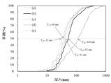
- Example 6 Using the specific complex (specific exfoliating compound) after the exfoliation treatment of Example 1 and Example 5 and the mica powder before the exfoliation treatment, the thickness in the c-axis direction was determined by the following method. First, the specific exfoliating compound was powdered by lyophilization. Next, the specific exfoliating compound and the mica powder before the exfoliation treatment were each mixed with water, a dispersant was added, and a dispersion slurry was prepared. A silicon mold was placed on the gypsum, the slurry was poured, and after 15 minutes of fleshing, it was air-dried overnight to obtain a disk-shaped molded body.
- FIG. 8 is a graph showing the thickness distribution of the specific composite (specific release compound) after the peeling treatment obtained in Example 5 and the mica powder before the peeling treatment obtained in Example 1. Also in the thickness distribution, the mica powder before peeling treatment (FIG. 8a, T 50 is 109 nm), the peeling compound of Example 1 (FIG.
- Example 8b T 50 is 52 nm
- 48 hours of Example 5 (FIG. 8c, T 50 is 41 nm)
- 72 hours (FIG. 8d, T 50 is 36 nm)
- 96 hours (FIG. 8e, T 50 was observed to turn a release of 32 nm) is in progress. It was shown that exfoliation progressed as the amount of intercalation increased. Furthermore, when the average particle diameter of the exfoliating compound of Example 1 and Example 5 was measured with a laser diffraction scattering system particle size distribution measuring device, it was 3.57 ⁇ m (Example 1) and 4.00 ⁇ m (Examples 5 and 48), respectively. Time) and 4.26 ⁇ m (Example 5, 72 hours) and 4.35 ⁇ m (Example 5, 96 hours).
- Example 7 Polypropylene (PP) pellets (FS2011DG3, specific gravity 0.9, manufactured by Sumitomo Chemical Co., Ltd.) 67.8 parts by mass in a plastic container, maleic anhydride-modified polypropylene granules (Yumex 1010, specific gravity 0.95, Sanyo Kasei) as a compatibilizing agent 17.9 parts by mass of Kogyo Co., Ltd.
- Example 5 14.3 parts by mass of the exfoliated compound (c-axis direction thickness 32 nm, average particle size 4.35 ⁇ m) obtained in Example 5 (96 hours) as an inorganic filler
- the shake-stirred mixture was put into a twin-screw kneading extruder (laboplast mill 10C100 / 2D15W type, manufactured by Toyo Seiki Co., Ltd.), a rotor speed of 300 rpm (min ⁇ 1 ), a set temperature of 230 ° C., and a T-die nozzle. was used to obtain a sheet-like sample having a thickness of 40 ⁇ m to 60 ⁇ m.
- the content of the compatibilizer is equivalent to 20% by volume with respect to the resin component (excluding the inorganic filler), and the inorganic filler addition rate is equivalent to 5% by volume with respect to the total amount of the mixture. .
- this sheet-like sample was cut into a 40 mm square and extruded using a biaxial stretching apparatus (IMC-18B2C-1 type, manufactured by Imoto Seisakusho Co., Ltd.) at a set temperature of 140 ° C. and a stretching speed of 120 mm / min in the longitudinal direction. The film was stretched 3.9 times to obtain a film sample having a thickness of 10 ⁇ m.
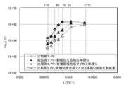
- the volume resistivity ⁇ from room temperature (27 ° C.) to 115 ° C. was measured for the obtained film sample by the method described later, the relationship between the measurement temperature T (K) and the volume resistivity ⁇ is shown in FIG. As shown.
- this sheet-like sample was cut into a 40 mm square and extruded using a biaxial stretching apparatus (IMC-18B2C-1 type, manufactured by Imoto Seisakusho Co., Ltd.) at a set temperature of 140 ° C. and a stretching speed of 120 mm / min in the longitudinal direction.
- the film was stretched 3.9 times to obtain a film sample having a thickness of 10 ⁇ m.
- the volume resistivity from room temperature (27 degreeC) to 115 degreeC was measured by the above-mentioned method, it was the result shown in FIG.
- this sheet-like sample was cut into a 40 mm square and extruded using a biaxial stretching apparatus (IMC-18B2C-1 type, manufactured by Imoto Seisakusho Co., Ltd.) at a set temperature of 140 ° C. and a stretching speed of 120 mm / min. And a film sample having a thickness of 10 ⁇ m was obtained.
- a biaxial stretching apparatus IMC-18B2C-1 type, manufactured by Imoto Seisakusho Co., Ltd.
- this sheet-like sample was cut into a 40 mm square and extruded using a biaxial stretching apparatus (IMC-18B2C-1 type, manufactured by Imoto Seisakusho Co., Ltd.) at a set temperature of 140 ° C. and a stretching speed of 120 mm / min. And a film sample having a thickness of 10 ⁇ m was obtained.
- a biaxial stretching apparatus IMC-18B2C-1 type, manufactured by Imoto Seisakusho Co., Ltd.
- the content of the compatibilizing agent corresponds to 20% by volume in terms of the charged volume fraction relative to the resin component (excluding inorganic filler), and the content of the inorganic filler corresponds to 5% by volume in terms of the charged volume fraction relative to the total amount of the mixture.
- this sheet-like sample was cut into a 40 mm square and extruded using a biaxial stretching apparatus (IMC-18B2C-1 type, manufactured by Imoto Seisakusho Co., Ltd.) at a set temperature of 140 ° C. and a stretching speed of 120 mm / min in the longitudinal direction. When the film was stretched 3.9 times, the film was torn and a film-like sample capable of evaluating the insulating properties could not be obtained.
- Table 2 shows sample specifications such as the composition of Example 7 and Comparative Examples 3 to 6. From FIG. 9 showing the temperature dependence of the volume resistivity measured for the samples of Example 7 and Comparative Examples 3 to 5, the following can be understood. From the comparison between Example 7 and Comparative Example 3 (that is, a film of polypropylene alone as a base resin), the volume resistivity decreased in the high temperature region of the insulating resin film to which the specific release compound was added as an inorganic filler. It is understood that the degree is equivalent to that of a single resin not added with an inorganic filler, and the insulating heat resistance of the insulating resin composition and the resin film is not deteriorated by the present invention.
- Comparative Example 4 in which the same amount of organically treated synthetic mica having excellent compatibility with the resin was added, although the film processability was obtained, the volume resistivity decreased greatly in the high temperature region, and the specific release compound was added to the inorganic filler. It can be seen that the insulation heat resistance deteriorates, unlike the insulating resin composition and resin film added. Moreover, it turns out that the deterioration of insulation heat resistance is still larger in the comparative example 5 which reduced the ratio of the compatibilizer with the combination of the same material as the comparative example 4.
- Example 8 74.3 parts by mass of polypropylene pellets (FS2011DG3, manufactured by Sumitomo Chemical Co., Ltd.) in a plastic container, maleic anhydride-modified polypropylene granules (Yumex 1010, specific gravity 0.95, manufactured by Sanyo Chemical Industries, Ltd.) 19.6 as a compatibilizer
- the mixture obtained by adding 6.1 parts by mass of the exfoliating compound (c-axis direction thickness 32 nm, average particle size 4.35 ⁇ m) obtained in Example 5 (96 hours) as a mass part and inorganic filler, and stirring and mixing the mixture.
- a twin-screw kneading extruder (labo plast mill 10C100 / 2D15W type, manufactured by Toyo Seiki Co., Ltd.) was extruded using a T-die nozzle at a rotor rotational speed of 300 rpm (min ⁇ 1 ) and a set temperature of 230 ° C.
- a sheet sample having a thickness of 40 ⁇ m to 60 ⁇ m was obtained.
- the content of the compatibilizing agent corresponds to 20% by volume with respect to the resin component (excluding inorganic filler), and the inorganic filler content corresponds to 2% by volume with respect to the total amount of the mixture. .
- this sheet-like sample was cut into a 40 mm square and extruded using a biaxial stretching apparatus (IMC-18B2C-1 type, manufactured by Imoto Seisakusho Co., Ltd.) at a set temperature of 140 ° C. and a stretching speed of 120 mm / min in the longitudinal direction.
- the film was stretched 3.9 times to obtain a film sample having a thickness of 10 ⁇ m.
- the dielectric breakdown strength in 25 degreeC and 85 degreeC was measured by the below-mentioned method, the result shown in FIG. 10 was obtained.
- a film-like sample is sandwiched between a cylindrical electrode (upper electrode) having a diameter of 20 mm at the contact portion between the flat electrode (lower electrode) and the object to be measured, and placed in a thermostat set at a predetermined temperature while immersed in oil. It was.
- a DC voltage with a constant boosting speed is output from a function generator (SG-4104, manufactured by Iwadori Measurement Co., Ltd.) and amplified using a high-voltage amplifier (10 / 40A-HS, manufactured by Trek Japan Co., Ltd.). was applied between the upper and lower electrodes and energized until dielectric breakdown occurred at a boosting rate of 500 V / s.
- the voltage value and current value output from the high-voltage amplifier are recorded using a data logger (GL200A type, manufactured by Graphtec Co., Ltd.), the voltage value at the time of dielectric breakdown is read, and the dielectric breakdown voltage (BDV: Break Down Voltage) It was.
- the dielectric breakdown voltage (BDS: Break Down Strength) (V / ⁇ m) was determined by dividing the dielectric breakdown voltage by the sample thickness ( ⁇ m).
- Comparative Example 7 A film-like sample was obtained using the same materials and processing conditions as in Comparative Example 3. About the obtained film-form sample, when the breakdown strength at 25 degreeC and 85 degreeC was measured by the above-mentioned method, the result shown in FIG. 10 was obtained.
- Table 3 shows sample specifications of Example 8 and Comparative Example 7 and a summary of measurement results of dielectric breakdown strength.
- the more the defects inside the sample that contribute to dielectric breakdown the more the data will vary, and the slope of the regression line of the Weibull plot will be smaller, so the larger the slope of the regression line, the better the material with fewer insulation properties. it is conceivable that.
- the dielectric breakdown strength (scale parameter) having a cumulative probability of 63.2% on the regression line was defined as the dielectric strength (V / ⁇ m) of the sample.
- Example 8 shows higher values of both the dielectric strength at high temperature (85 ° C.) and the slope of the regression line than Comparative Example 7, and the insulation breakdown voltage from room temperature (25 ° C.) to high temperature ( From the fact that the rate of decrease to 85 ° C. is also low, it can be seen that the addition of the specific release compound improves the dielectric breakdown resistance at high temperatures of the insulating resin composition and the resin film.
Landscapes
- Chemical & Material Sciences (AREA)
- Health & Medical Sciences (AREA)
- Chemical Kinetics & Catalysis (AREA)
- Medicinal Chemistry (AREA)
- Polymers & Plastics (AREA)
- Organic Chemistry (AREA)
- Engineering & Computer Science (AREA)
- Manufacturing & Machinery (AREA)
- Materials Engineering (AREA)
- Compositions Of Macromolecular Compounds (AREA)
- Manufacture Of Macromolecular Shaped Articles (AREA)
Abstract
絶縁性樹脂組成物は、熱可塑性樹脂と無機フィラとを含有し、前記無機フィラの少なくとも一部が、c軸方向の平均粒子厚さが1nm~80nmである剥離化された層状無機化合物である。
Description
本発明は、絶縁性樹脂組成物、樹脂シート、樹脂フィルム及び絶縁物に関する。
各種電気電子機器の絶縁性部材には、絶縁性、化学的安定性、機械的強度、耐熱性、コスト等の観点から、多くの場合に樹脂をベース材料とする絶縁樹脂材料が用いられている。
上述したような用途において、電気的特性としてのより優れた絶縁性及び耐電圧性、熱的特性としての耐熱性、並びに機械的性質としての高靱性、高弾性、柔軟性及びガスバリア性のような種々の性能が必要とされている。かかる性能を補償するために、特開2008-75069号公報では、絶縁樹脂にシリカ、アルミナ、スメクタイト系粘土化合物等の無機化合物を充填することが行われている。
ところで、特開平9-208745号公報及び特開2008-7753号公報では、マイカ等の層状無機化合物とポリプロピレン、ポリアミド等の熱可塑性樹脂とを複合化させることにより、その複合材料の絶縁性、耐電圧性、耐熱性等の諸性能を向上させる試みがなされている。これらの先行技術において、熱可塑性樹脂と層状無機化合物を分散する場合、層状無機化合物を熱可塑性樹脂に溶融混練する方法が用いられている。
溶融混練により層状無機化合物を熱可塑性樹脂に分散する場合、ポリプロピレン等の熱可塑性樹脂に熱が加えられる。しかし、分散を促進させるには、熱可塑性樹脂に対してより大きなせん断力をより長時間加える必要があり、熱可塑性樹脂の熱劣化が生じる可能性がある。更に、意図しない混練条件の変化、変動又は不均一性により、層状無機化合物の熱可塑性樹脂への分散の均一性又は再現性の損なわれる可能性があり、ひいては、複合材料についての所望の材料特性が損なわれる可能性がある。
また、層状無機化合物は本来、層間に親水性を示すナトリウム、カリウム等のアルカリ金属を含み、また、結晶表面に水酸基を有するため、水等の極性溶剤に対しては親和性を示すが、有機溶剤、樹脂等の有機物質に対する親和性は低い。そのため、樹脂との混練に於いて、層状無機化合物の凝集及び凝集に伴う空隙が発生してしまい、樹脂に層状無機化合物を均一に分散させることが困難となり、加工性、絶縁性、耐電圧性、耐熱性等の諸性能が低下してしまうという問題がある。
加えて、絶縁樹脂材料には、高い信頼性が求められているため、より優れた絶縁性、高熱伝導性、耐電圧性等の諸性能を向上させるために、一定量以上の層状無機化合物の充填が必要である。しかし、充填率を高くすると層状無機化合物の周囲の空間部に樹脂が回り込まずに空隙が形成されやすくなり、絶縁樹脂材料の諸性能の低下に加えて、製造コストが増加するという問題点を有する。この問題を解決するために、層状無機化合物のアスペクト比(縦横比)を増加させること、つまり比表面積を増加させることが有効である。特開平9-87096号公報には、アスペクト比を増加させた層状無機化合物であるスメクタイト系粘土化合物と樹脂の複合材料では、機械的特性が向上することが報告されている。スメクタイト系粘土化合物同様、層状無機化合物であるマイカもアスペクト比が大きいほど樹脂と複合化した材料の絶縁性、耐電圧性、耐熱性等の改善効果が高くなると考えられている。そのため、これら課題を実現するために、層状無機化合物の剥離技術(ナノシート化技術)の開発が求められている。
層状無機化合物を効果的に剥離するためには、層間の結合力を低下させることが有効である。層状無機化合物中のナノシート内の原子は共有結合等によって非常に強く結合されている。一方、層状無機化合物の層間はファンデルワールス力、静電相互作用等の比較的弱い結合によって形成されている。このファンデルワールス力は、一般的に式(1)で示すLennard-Jonesポテンシャルの分散力(式中の6次の項)で表すことができ、距離rの6乗に反比例することが知られている。また、静電相互作用については式(2)で表すことができ、距離rに反比例することが分かっている。このように、層間の距離を広げることで結合力を弱めることができるため、効果的に剥離を達成するためには層間を広げるための技術開発が求められる。

ここで、U(r)は任意の分子対のポテンシャルエネルギー、ε及びδは分子に固有のフィッテングパラメータ、q+及びq-は電荷量、εrは媒質の比誘電率、ε0は真空の誘電率、rは距離を指す。
上述した通り、層状無機化合物を樹脂に均一に分散するためには、層状無機化合物と樹脂の親和性の向上及び層状無機化合物の剥離技術の開発が必要不可欠である。そこで、この問題を解決するために、本発明者等は、層状無機化合物の層間に有機化合物をインターカレートする方法(インターカレーション)について鋭意研究を重ね、層状無機化合物と有機化合物との複合体及びその製造方法(つまり、有機化処理)並びに剥離化された層状無機化合物及びその製造方法について研究を行っている。
インターカレーションとは、層状無機化合物の層間に原子、分子等が入り込む現象のことである。インターカレーションの前後において、結晶構造の変化がないことから、層状無機化合物の剥離の前処理及び樹脂と層状無機化合物の親和性向上のための操作としてスメクタイトのような粘土化合物等にインターカレーションが用いられている。インターカレーションによって有機化処理された層状無機化合物は、ナイロン樹脂等の樹脂に対して親和性を示す。特開昭63-215775号公報では、マトリクスとなる樹脂中に直接層状無機化合物とモノマー等の有機化合物を加えて混練し重合することによって層状無機化合物を樹脂中に均一に分散させている。また、特開2004-169030号公報では、有機化処理した層状無機化合物を超音波照射等の強い条件で分散処理して粉砕した層状無機化合物を得る試みがなされている。
また、これまでに、樹脂組成物の絶縁性能を向上させ、例えば、電気トリーの進展を抑制するために、樹脂組成物の中に層状無機化合物であるナノメートルサイズの無機ナノ粒子を分散する手法が用いられている。
例えば、特開2009-191239号公報では、層状無機化合物の層間にイオン交換処理により有機化合物を挿入することで有機化処理された層状無機化合物を、有機溶剤で膨潤させる。その後、膨潤した層状無機化合物を樹脂と混練することにより、層状無機化合物を層間剥離させる。剥離した層状無機化合物の各層は樹脂中に均一分散する。そのため、特開2009-191239号公報では、耐部分放電性の向上した樹脂組成物を得ることができることが記載されている。
また、特開2012-158622号公報には、層状無機化合物を水、又は水系混合溶剤で膨潤させた後、更にシランカップリング剤により有機官能化された層状無機化合物を樹脂と混練することにより、絶縁性能が向上した高電圧機器用樹脂組成物の製造方法が記載されている。
特開2009-191239号公報及び特開2012-158622号公報に記載された層状無機化合物であるクレイに対し、特開2008-63408号公報及び国際公開2006/22431号には層状無機化合物であるマイカを用いることが記載されている。
具体的に、特開2008-63408号公報では、樹脂と、有機修飾剤を層状無機化合物のマイカにインターカレートした層間化合物とを、混練装置を用いて、層間化合物中の有機修飾剤の蒸発温度にて溶融混練する。これにより、マイカの剥離分散性を著しく進行させることを見出した旨が記載されている。
国際公開2006/22431号は、一次粒子径の大きな非膨潤性のマイカを正電荷有機化合物の濃厚溶液で処理することにより得られる有機-無機複合体及び該有機-無機複合体を良好に分散した高分子複合材料に関するものである。
特開昭63-215775号公報の方法では重合反応を用いるため、ベースとなる樹脂のモノマー及びインターカレートする有機化合物の種類と量に応じて、反応方法を考慮する必要があり、製造コストを増大させてしまうという問題がある。また、特開2004-169030号公報の方法では、超音波によってマイカが剥離ではなく、粉砕され、マイカの長手方向(a軸)の長さが小さくなってしまい、アスペクト比が低下する問題がある。更に、スメクタイト等の粘土化合物の層間にナトリウムイオンを含む膨潤性無機化合物では、水、有機溶剤等を層間に取り込み膨潤するためインターカレーションが起きやすい。しかし、層間にカリウムイオンを含む非膨潤性マイカでは上記のような現象が起きにくいため、インターカレーションが困難であるという問題がある。
また、樹脂組成物の絶縁性能の向上を目的に、樹脂組成物の中に層状粘土鉱物からなるナノメートルサイズの無機ナノ粒子を分散する手法として特開2009-191239号公報、特開2012-158622号公報、特開2008-63408号公報及び国際公開2006/22431号が挙げられているが、これらの手法には、それぞれの課題がある。
特開2009-191239号公報に記載された手法の課題として、有機化合物はイオン交換の際、イオン交換率を高めるために、層状粘土鉱物のイオン交換能よりも過剰の有機化合物を投入する。そのため、層間に挿入されていない有機化合物、各種金属イオン等が残存することになる。
その後、そのまま樹脂と混練して樹脂組成物を製造するため、最終的に得られる樹脂組成物の中に、残存有機化合物及び各種金属イオンが多量に存在する。そのため、樹脂組成物の絶縁性向上効果が小さいと考えられる。
一方、特開2012-158622号公報に記載された手法では、水系でなければならないという課題がある。疎水性の樹脂との相溶性の問題及び水の沸点以上の高温での処理に適さないことにより、特開2012-158622号公報に記載された手法は樹脂組成物の製造には適用できないと考えられる。
更に、特開2008-63408号公報に記載された手法の課題として、層間粘土鉱物中の有機修飾剤の蒸発温度にて溶融混練しなければならないため、例えば、有機修飾剤の種類と適用樹脂に適した混練温度の組み合わせが限定されることが挙げられる。
更に、国際公開2006/22431号に記載された手法の課題として、層状無機化合物が高分子との複合化過程、すなわち混練工程においてのみ剥片化される。そのため、十分な効果を得るための複合化方法及び複合化条件が限定されることが挙げられる。
上述のように、樹脂とアルミナ等の無機フィラとを含む絶縁性樹脂組成物の熱伝導率を維持しながら、その絶縁性能も向上させた例が記載されていない。これまで、高い成形性と高い絶縁信頼性を兼ね備えた層状無機化合物が充填された絶縁性樹脂組成物の開発には至っていないのが現状である。
従って、本発明は、高い絶縁耐電圧を備える絶縁性樹脂組成物並びにそれを用いた樹脂シート、樹脂フィルム及び絶縁物を提供することを目的とする。
前記課題を達成するための具体的手段は以下の通りである。
<1> 熱可塑性樹脂と無機フィラとを含有し、前記無機フィラの少なくとも一部が、c軸方向の平均粒子厚さが1nm~80nmである剥離化された層状無機化合物である絶縁性樹脂組成物。
<1> 熱可塑性樹脂と無機フィラとを含有し、前記無機フィラの少なくとも一部が、c軸方向の平均粒子厚さが1nm~80nmである剥離化された層状無機化合物である絶縁性樹脂組成物。
<2> 前記剥離化された層状無機化合物の含有率が、1体積%~10体積%である<1>に記載の絶縁性樹脂組成物。
<3> <1>又は<2>に記載の絶縁性樹脂組成物をシート状に成形してなる樹脂シート。
<4> <1>又は<2>に記載の絶縁性樹脂組成物をフィルム状に成形してなる樹脂フィルム。
<5> <1>又は<2>に記載の絶縁性樹脂組成物の成形物である絶縁物。
本発明によれば、高い絶縁耐電圧を備える絶縁性樹脂組成物並びにそれを用いた樹脂シート、樹脂フィルム及び絶縁物が提供される。
以下、本発明を実施するための形態について詳細に説明する。但し、本発明は以下の実施形態に限定されるものではない。以下の実施形態において、その構成要素(要素ステップ等も含む)は、特に明示した場合、原理的に明らかに必須であると考えられる場合等を除き、必須ではない。数値及びその範囲についても同様であり、本発明を制限するものではない。
本明細書において「工程」との語は、独立した工程だけではなく、他の工程と明確に区別できない場合であってもその工程の目的が達成されれば、本用語に含まれる。
また「~」を用いて示された数値範囲は、「~」の前後に記載される数値をそれぞれ最小値及び最大値として含む範囲を示す。
本明細書中に段階的に記載されている数値範囲において、一つの数値範囲で記載された上限値又は下限値は、他の段階的な記載の数値範囲の上限値又は下限値に置き換えてもよい。また、本明細書中に記載されている数値範囲において、その数値範囲の上限値又は下限値は、実施例に示されている値に置き換えてもよい。
さらに、組成物中の各成分の含有量は、組成物中に各成分に該当する物質が複数種存在する場合、特に断らない限り、組成物中に存在する当該複数種の物質の合計量を意味する。
さらに、組成物中の各成分の粒子径は、組成物中に各成分に該当する粒子が複数種存在する場合、特に断らない限り、組成物中に存在する当該複数種の粒子の混合物についての値を意味する。
本明細書において「工程」との語は、独立した工程だけではなく、他の工程と明確に区別できない場合であってもその工程の目的が達成されれば、本用語に含まれる。
また「~」を用いて示された数値範囲は、「~」の前後に記載される数値をそれぞれ最小値及び最大値として含む範囲を示す。
本明細書中に段階的に記載されている数値範囲において、一つの数値範囲で記載された上限値又は下限値は、他の段階的な記載の数値範囲の上限値又は下限値に置き換えてもよい。また、本明細書中に記載されている数値範囲において、その数値範囲の上限値又は下限値は、実施例に示されている値に置き換えてもよい。
さらに、組成物中の各成分の含有量は、組成物中に各成分に該当する物質が複数種存在する場合、特に断らない限り、組成物中に存在する当該複数種の物質の合計量を意味する。
さらに、組成物中の各成分の粒子径は、組成物中に各成分に該当する粒子が複数種存在する場合、特に断らない限り、組成物中に存在する当該複数種の粒子の混合物についての値を意味する。
<絶縁性樹脂組成物>
本実施形態の絶縁性樹脂組成物は、熱可塑性樹脂と無機フィラとを含有し、前記無機フィラの少なくとも一部が、c軸方向の平均粒子厚さが1nm~80nmである剥離化された層状無機化合物(以下、当該層状無機化合物を「特定剥離化化合物」と称することがある)としたものである。
本実施形態の絶縁性樹脂組成物は、熱可塑性樹脂と無機フィラとを含有し、前記無機フィラの少なくとも一部が、c軸方向の平均粒子厚さが1nm~80nmである剥離化された層状無機化合物(以下、当該層状無機化合物を「特定剥離化化合物」と称することがある)としたものである。
従来、異方性が小さく、球状のシリカ、アルミナ等を含有する絶縁性樹脂組成物は、絶縁破壊のパスが短く、絶縁性樹脂組成物の絶縁破壊電圧が低下するため、鱗片状フィラを添加しなければならないことがあった。
しかし、ミクロンオーダー又はそれ以上のサイズの鱗片状フィラを絶縁性樹脂組成物に含有させると、加工成形性が低下し、特に延伸加工等によるフィルム化が困難となりやすい。それを防止するために、ナノメートルサイズの無機ナノ粒子を使用することがより有効であると考えられる。
無機ナノ粒子として、ナノサイズのBN(窒化ホウ素)、マイカ等の層状無機化合物などが考えられる。しかし、BNの場合は表面官能基が少ないため、熱可塑性樹脂との親和性に乏しく、絶縁性樹脂組成物の内部にボイドが発生しやすく、絶縁性が低下することがある。
我々は上述の課題を解決すべく鋭意検討した結果、特定の厚さに剥片化された層状無機化合物(特定剥離化化合物)を用いることで、高い絶縁信頼性を備える絶縁性樹脂組成物を製造することが可能になることを見出した。これによって、より汎用的な簡便な工程で、高い絶縁耐電圧を備える絶縁性樹脂組成物並びにそれを用いた樹脂シート、樹脂フィルム及び絶縁物を実現するに至った。
本実施形態で用いられる特定剥離化化合物は、電気絶縁性はもちろん、耐熱性、耐薬品性等にも優れていて、更に、コストパフォーマンスに優れている。
以下、本実施形態の絶縁性樹脂組成物の構成成分等について説明する。
(熱可塑性樹脂)
本実施形態の絶縁性樹脂組成物は、熱可塑性樹脂の少なくとも一種を含有する。熱可塑性樹脂としては、例えば、ポリエチレン、ポリプロピレン、ポリエチレンテレフタレート、ポリブチレンテレフタレート、ポリ塩化ビニル、ポリ塩化ビニリデン、ポリフッ化ビニリデン、ポリアセタール、ポリフェニレンスルフィド、ポリフェニレンエーテル、ポリエーテルエーテルケトン、ポリサルフォン、ポリエーテルサルフォン、ポリ酢酸ビニル、エチレン-酢酸ビニル共重合体、ポリスチレン、アクリロニトリル-ブタジエン-スチレン共重合体、アクリロニトリル-スチレン共重合体、ポリ乳酸、ポリカプロラクトン、ポリブチレンサクシネート、ポリメチルメタクリレート、ポリアミド、ポリカーボネート、ポリアミドイミド、ポリエーテルイミド及び熱可塑性ポリイミドが挙げられる。
(熱可塑性樹脂)
本実施形態の絶縁性樹脂組成物は、熱可塑性樹脂の少なくとも一種を含有する。熱可塑性樹脂としては、例えば、ポリエチレン、ポリプロピレン、ポリエチレンテレフタレート、ポリブチレンテレフタレート、ポリ塩化ビニル、ポリ塩化ビニリデン、ポリフッ化ビニリデン、ポリアセタール、ポリフェニレンスルフィド、ポリフェニレンエーテル、ポリエーテルエーテルケトン、ポリサルフォン、ポリエーテルサルフォン、ポリ酢酸ビニル、エチレン-酢酸ビニル共重合体、ポリスチレン、アクリロニトリル-ブタジエン-スチレン共重合体、アクリロニトリル-スチレン共重合体、ポリ乳酸、ポリカプロラクトン、ポリブチレンサクシネート、ポリメチルメタクリレート、ポリアミド、ポリカーボネート、ポリアミドイミド、ポリエーテルイミド及び熱可塑性ポリイミドが挙げられる。
本実施形態の絶縁性樹脂組成物における熱可塑性樹脂の含有率は特に制限されない。例えば本実施形態の絶縁性樹脂組成物の固形分中に、50質量%~99質量%とすることができ、65質量%~99質量%であることが好ましく、85質量%~99質量%であることがより好ましい。熱可塑性樹脂の含有率が上記範囲であることで、成形性をより向上することができる。なお、絶縁性樹脂組成物の固形分とは絶縁性樹脂組成物から揮発性成分を除いた残分を意味する。
(無機フィラ)
本実施形態の絶縁性樹脂組成物は、無機フィラを含有する。本実施形態において無機フィラの少なくとも一部が特定剥離化化合物とされる。特定剥離化化合物の製造方法については後述する。
特定剥離化化合物の含有率(つまり、絶縁性樹脂組成物に占める割合)は、1体積%~10体積%の範囲とすることが好ましく、2体積%~7体積%の範囲とすることがより好ましい。特定剥離化化合物の含有率が1体積%以上の場合、本実施形態の絶縁性樹脂組成物の絶縁性がより向上する傾向にある。一方、特定剥離化化合物の含有率が10体積%以下の場合、本実施形態の絶縁性樹脂組成物の成形性がより向上する傾向にある。
本実施形態の絶縁性樹脂組成物は、無機フィラを含有する。本実施形態において無機フィラの少なくとも一部が特定剥離化化合物とされる。特定剥離化化合物の製造方法については後述する。
特定剥離化化合物の含有率(つまり、絶縁性樹脂組成物に占める割合)は、1体積%~10体積%の範囲とすることが好ましく、2体積%~7体積%の範囲とすることがより好ましい。特定剥離化化合物の含有率が1体積%以上の場合、本実施形態の絶縁性樹脂組成物の絶縁性がより向上する傾向にある。一方、特定剥離化化合物の含有率が10体積%以下の場合、本実施形態の絶縁性樹脂組成物の成形性がより向上する傾向にある。
本実施形態において、特定剥離化化合物以外の無機フィラを使用する場合、特定剥離化化合物以外の無機フィラは、特に限定されず、当技術分野において周知の化合物を使用することができる。例えば、酸化アルミニウム(アルミナ)、酸化マグネシウム、酸化ケイ素、水酸化アルミニウム、酸化チタン、酸化ジルコニウム及び炭酸カルシウムが挙げられる。
本実施形態において、特定剥離化化合物以外の無機フィラを使用する場合、特定剥離化化合物の無機フィラに占める割合は、5質量%~100質量%の範囲とすることが好ましく、20質量%~100質量%の範囲とすることがより好ましく、50質量%~100質量%の範囲とすることが更に好ましい。
本実施形態において、特定剥離化化合物の平均粒子径は、0.1μm~20μmが好ましく、0.5μm~10μmがより好ましく、1μm~6μmが更に好ましい。
また、本実施形態において、特定剥離化化合物のc軸方向の平均粒子厚さは1nm~80nmであり、10nm~70nmであることが好ましく、20nm~50nmであることがより好ましい。特定剥離化化合物のc軸方向の平均粒子厚さが1nm以上であれば、特定剥離化化合物が割れにくい傾向にある。特定剥離化化合物のc軸方向の平均粒子厚さが80nm以下であれば、絶縁信頼性が向上する傾向にある。
また、本実施形態において、特定剥離化化合物のc軸方向の平均粒子厚さは1nm~80nmであり、10nm~70nmであることが好ましく、20nm~50nmであることがより好ましい。特定剥離化化合物のc軸方向の平均粒子厚さが1nm以上であれば、特定剥離化化合物が割れにくい傾向にある。特定剥離化化合物のc軸方向の平均粒子厚さが80nm以下であれば、絶縁信頼性が向上する傾向にある。
本実施形態において、特定剥離化化合物等の粒子の平均粒子径は、レーザー回折散乱方式粒度分布測定装置を用いることで測定可能である。分散液中に測定対象物を投入した後に、撹拌機等で分散する。この分散液の粒子径分布を測定することで測定対象物の粒子径分布が測定される。粒子径分布に基づいて、平均粒子径は、小径側からの体積累積50%に対応する粒子径として求められる。
(添加剤)
本実施形態の絶縁性樹脂組成物は、添加剤を必要に応じて更に含むことができる。添加剤としては、例えば、特定剥離化化合物の剥離性及び分散性を向上させることができるエラストマ、カップリング剤、変性熱可塑性樹脂等の相溶化剤などを挙げることができる。その他に、酸化防止剤、老化防止剤、安定剤、難燃剤、増粘剤等の樹脂組成物に一般に用いられる各種添加剤を挙げることができる。本実施形態の絶縁性樹脂組成物が添加剤を更に含有する場合、これらの添加剤の含有量は本発明の効果を損なわない範囲であれば特に制限されない。
本実施形態の絶縁性樹脂組成物は、添加剤を必要に応じて更に含むことができる。添加剤としては、例えば、特定剥離化化合物の剥離性及び分散性を向上させることができるエラストマ、カップリング剤、変性熱可塑性樹脂等の相溶化剤などを挙げることができる。その他に、酸化防止剤、老化防止剤、安定剤、難燃剤、増粘剤等の樹脂組成物に一般に用いられる各種添加剤を挙げることができる。本実施形態の絶縁性樹脂組成物が添加剤を更に含有する場合、これらの添加剤の含有量は本発明の効果を損なわない範囲であれば特に制限されない。
(特定剥離化化合物の製造方法)
本実施形態で用いられる特定剥離化化合物は、c軸方向の平均粒子厚さが1nm~80nmである剥離化された層状無機化合物であれば特に限定されるものではない。
特定剥離化化合物は、例えば、単位結晶層が互いに積み重なって層状構造をなしており、熱分解温度の上限値で1時間加熱することによって0.05Å~0.20Åの範囲でc軸方向に膨張し、熱分解温度の上限値で1時間加熱することによって単位結晶層の結晶構造が変化しない非膨潤性層状無機化合物に有機化合物をインターカレートしてなる層状無機化合物と有機化合物との複合体を用いて製造することができる。以下、層状無機化合物と有機化合物との複合体を、「特定複合体」と称することがある。
本実施形態で用いられる特定剥離化化合物は、c軸方向の平均粒子厚さが1nm~80nmである剥離化された層状無機化合物であれば特に限定されるものではない。
特定剥離化化合物は、例えば、単位結晶層が互いに積み重なって層状構造をなしており、熱分解温度の上限値で1時間加熱することによって0.05Å~0.20Åの範囲でc軸方向に膨張し、熱分解温度の上限値で1時間加熱することによって単位結晶層の結晶構造が変化しない非膨潤性層状無機化合物に有機化合物をインターカレートしてなる層状無機化合物と有機化合物との複合体を用いて製造することができる。以下、層状無機化合物と有機化合物との複合体を、「特定複合体」と称することがある。
特定複合体は、例えば、単位結晶層が互いに積み重なって層状構造をなしており、熱分解温度の上限値で1時間加熱することによって0.05Å~0.20Åの範囲でc軸方向に膨張し、熱分解温度の上限値で1時間加熱することによって単位結晶層の結晶構造が変化しない非膨潤性層状無機化合物を、非膨潤性層状無機化合物の熱分解温度の範囲内で加熱処理する工程と、加熱処理された非膨潤性層状無機化合物を媒体に分散させた分散液中で、非膨潤性層状無機化合物に有機化合物をインターカレートさせて非膨潤性層状無機化合物の層間に有機化合物を挿入する工程と、を経て製造することができる。
本発明者らは、非膨潤性層状無機化合物に有機化合物をインターカレートするために鋭意研究を重ねた。その結果、非膨潤性層状無機化合物を、非膨潤性層状無機化合物の熱分解温度の範囲内で加熱処理し、非膨潤性層状無機化合物をc軸方向に膨張させることによって有機化合物を容易に層間にインターカレートして特定複合体を形成できることを見出した。
特定複合体は、層状無機化合物を剥離化する際の前段階の物質として有用である。
特定複合体は、層状無機化合物を剥離化する際の前段階の物質として有用である。
以下、特定複合体の製造方法を具体的に説明する。
本実施形態において用いられる非膨潤性層状無機化合物としては、マイカ、カオリナイト、パイロフィライト等が挙げられる。これらの中でも、絶縁性に優れるマイカが好ましい。非膨潤性のマイカとしては、白雲母、黒雲母、パラゴナイト、マーガライト、クリントナイト、アナンダイト、クロライト、フロゴパイト、レピドライト、マスコバイト、バイオタイト、テニオライト、テトラシリシックマイカ等が挙げられる。ただし、本実施形態で用いられる非膨潤性層状無機化合物としては、熱分解温度の上限値で1時間加熱することによって0.05Å~0.20Åの範囲でc軸方向に膨張し、熱分解温度の上限値で1時間加熱することによって単位結晶層の結晶構造が変化しないことが必要である。本実施形態において、非膨潤性層状無機化合物としてマイカが用いられる場合、マイカの種類は特に限定されるものではなく、天然物であってもよく、水熱合成法、溶融法、固相法等による合成物であってもよい。
なお、非膨潤性層状無機化合物は、単位結晶層が互いに積み重なって層状構造をなす化合物である。
本実施形態において用いられる非膨潤性層状無機化合物としては、マイカ、カオリナイト、パイロフィライト等が挙げられる。これらの中でも、絶縁性に優れるマイカが好ましい。非膨潤性のマイカとしては、白雲母、黒雲母、パラゴナイト、マーガライト、クリントナイト、アナンダイト、クロライト、フロゴパイト、レピドライト、マスコバイト、バイオタイト、テニオライト、テトラシリシックマイカ等が挙げられる。ただし、本実施形態で用いられる非膨潤性層状無機化合物としては、熱分解温度の上限値で1時間加熱することによって0.05Å~0.20Åの範囲でc軸方向に膨張し、熱分解温度の上限値で1時間加熱することによって単位結晶層の結晶構造が変化しないことが必要である。本実施形態において、非膨潤性層状無機化合物としてマイカが用いられる場合、マイカの種類は特に限定されるものではなく、天然物であってもよく、水熱合成法、溶融法、固相法等による合成物であってもよい。
なお、非膨潤性層状無機化合物は、単位結晶層が互いに積み重なって層状構造をなす化合物である。
非膨潤性層状無機化合物のc軸方向の膨張の程度は、X線回折装置(X-Ray Diffraction、XRD)により測定することができる。加熱前後の非膨潤性層状無機化合物の(002)のピークのシフト位置を測定することで、c軸方向の距離の変化を計測することが可能である。
熱分解温度の上限値で1時間加熱することによって非膨潤性層状無機化合物の単位結晶層の結晶構造が変化したか否かは、加熱前後の非膨潤性層状無機化合物をXRDで測定し、同定分析することで結晶構造の変化を測定することにより確認が可能である。
特定複合体は、層状無機化合物の層間に有機化合物をインターカレートすることにより得られる。特定剥離化化合物を絶縁性樹脂組成物に用いる場合における熱可塑性樹脂との親和性を考慮し、インターカレートする物質は有機化合物とされる。本実施形態で用いられる有機化合物は、特にその種類に限定はなく、アミン塩、ホスホニウム塩、イミダゾリウム塩、ピリジニウム塩、スルホニウム塩及びヨードニウム塩からなる群より選択される少なくとも一種のカチオン性有機化合物が挙げられる。
本実施形態において使用可能なアミン塩としては、ドデシルアミン塩酸塩、オクタデシルアミン塩酸塩等の第1級から第4級のアミン塩酸塩などが挙げられる。
本実施形態において使用可能なホスホニウム塩としては、トリヘキシルホスホニウム塩等が挙げられる。
本実施形態において使用可能なイミダゾリウム塩としては、1-エチル-3-メチルイミダゾリウム塩等が挙げられる。
本実施形態において使用可能なピリジニウム塩としては、N-アルキルピリジニウム塩等が挙げられる。
本実施形態において使用可能なスルホニウム塩としては、トリアリールスルホニウム塩等が挙げられる。
本実施形態において使用可能なヨードニウム塩としては、N-アルキルヨードニウム塩等が挙げられる。
本実施形態において使用可能なホスホニウム塩としては、トリヘキシルホスホニウム塩等が挙げられる。
本実施形態において使用可能なイミダゾリウム塩としては、1-エチル-3-メチルイミダゾリウム塩等が挙げられる。
本実施形態において使用可能なピリジニウム塩としては、N-アルキルピリジニウム塩等が挙げられる。
本実施形態において使用可能なスルホニウム塩としては、トリアリールスルホニウム塩等が挙げられる。
本実施形態において使用可能なヨードニウム塩としては、N-アルキルヨードニウム塩等が挙げられる。
有機化合物を層間に挿入することにより、層間距離を長くし、しかも層間を親油性とすることができるので、特定複合体から調製される特定剥離化化合物の樹脂に対する親和性が向上し、樹脂中により均一に特定剥離化化合物を分散することが可能である。
特定複合体の製造方法における非膨潤性層状無機化合物を加熱処理する工程では、非膨潤性層状無機化合物の熱分解温度の範囲内で非膨潤性層状無機化合物が加熱される。加熱温度が非膨潤性層状無機化合物の熱分解温度の上限値を超えると、非膨潤性層状無機化合物の構造水(結晶構造中の水酸基)が除去されてしまい、非膨潤性層状無機化合物の結晶構造が変化してしまう傾向にあり、非膨潤性層状無機化合物自体の変質を招くので好ましくない。また、加熱温度が非膨潤性層状無機化合物の熱分解温度の下限値未満であると、非膨潤性層状無機化合物の結晶のゆらぎが起きにくく層間が広がりにくいため、インターカレーションが十分に起こらない傾向にある。そのため、非膨潤性層状無機化合物の加熱処理温度は非膨潤性層状無機化合物の熱分解温度の範囲内とされる。なお、非膨潤性層状無機化合物を加熱処理する工程を実施する前に、熱重量測定、X線回折測定等によって、非膨潤性層状無機化合物の結晶構造が変化する温度(即ち、熱分解温度)が予め確認される。
なお、非膨潤性層状無機化合物の熱分解温度は、上限値と下限値とを有する温度範囲を意味する。
本実施形態において、非膨潤性層状無機化合物の熱分解温度の確認方法の詳細は、以下の通りである。熱分解温度は、熱重量測定(Thermo Gravimetry、TG)及び示差熱分析(Differential Thermal Analysis、DTA)を用いることで測定が可能である。非膨潤性層状無機化合物を500℃以上で加熱し、DTAの、吸熱反応及び発熱反応のピーク形状、吸熱反応及び発熱反応のピーク温度等から熱分解温度を簡易的に測定することが可能である。詳細な方法としては、加熱した非膨潤性層状無機化合物についての構造水のピーク波長、結晶構造の変化等を、赤外吸収又はX線回折装置を用いて観察することが好ましい。
なお、非膨潤性層状無機化合物の熱分解温度は、上限値と下限値とを有する温度範囲を意味する。
本実施形態において、非膨潤性層状無機化合物の熱分解温度の確認方法の詳細は、以下の通りである。熱分解温度は、熱重量測定(Thermo Gravimetry、TG)及び示差熱分析(Differential Thermal Analysis、DTA)を用いることで測定が可能である。非膨潤性層状無機化合物を500℃以上で加熱し、DTAの、吸熱反応及び発熱反応のピーク形状、吸熱反応及び発熱反応のピーク温度等から熱分解温度を簡易的に測定することが可能である。詳細な方法としては、加熱した非膨潤性層状無機化合物についての構造水のピーク波長、結晶構造の変化等を、赤外吸収又はX線回折装置を用いて観察することが好ましい。
この有機化合物を非膨潤性層状無機化合物の層間にインターカレートさせる反応(つまり、非膨潤性層状無機化合物の層間に有機化合物を挿入する工程)は、加熱処理によって非膨潤性層状無機化合物の結晶を不安定にし、c軸方向に膨張させて層間を広げた後、加熱処理された非膨潤性層状無機化合物を媒体に分散させた分散液中にゲスト化合物として有機化合物を加え、加熱及び撹拌することによりなされてもよい。分散液中における有機化合物の濃度は、非膨潤性層状無機化合物と有機化合物との接触回数を増加させるため、0.01mol/L以上の濃度で高い方が好ましい。ただし、有機化合物の濃度が一定以上を超えると、分散液の粘度が著しく増加することがあるため、分散液中における有機化合物の濃度は、有機化合物の溶解度以下に調製することが好ましい。
また、分散液中における非膨潤性層状無機化合物の含有率は0.5体積%~50体積%の範囲が好ましい。50体積%以下であれば、分散液の粘度が高くなりすぎないため撹拌効率の低下が抑制される傾向にある。0.5体積%以上であれば、生成される特定複合体の量として、工業的に量産できる程度の量を確保できる傾向にある。
加熱処理された非膨潤性層状無機化合物を分散する媒体としては、特に限定されるものでなく、インターカレートする有機化合物が溶解する溶剤であればよい。具体的には、水、アルコール等の有機溶剤などが挙げられる。インターカレートさせる有機化合物を含有する媒体中に、加熱処理された非膨潤性層状無機化合物を分散してもよい。
更に、インターカレーション反応する際の温度は高くなるにつれて反応速度が進むため、室温(25℃)以上が好適である。
非膨潤性層状無機化合物の層間にインターカレートした有機化合物は、非膨潤性層状無機化合物100質量%に対して1質量%~40質量%が好ましく、より好ましくは1質量%~30質量%であり、更に好ましくは1質量%~25質量%である。インターカレートした有機化合物の量が非膨潤性層状無機化合物100質量%に対して1質量%~40質量%であることにより、非膨潤性層状無機化合物の効率的な機械的剥離処理には好適である。インターカレートする有機化合物の量が1質量%以上であれば、非膨潤性層状無機化合物の層間を剥離化に適切な範囲まで広げることが可能となり、非膨潤性層状無機化合物を効果的に剥離させ、ナノシート化しやすい傾向にある。
非膨潤性層状無機化合物の層間に有機化合物を挿入する工程の後、未反応の有機化合物を除去した後、インターカレートした特定複合体を媒体に再分散させてもよい。
未反応の有機化合物を除去する方法としては、例えば、インターカレートした特定複合体を水又は有機溶剤に分散し、ろ過、フィルタープレス、遠心分離等で回収する洗浄方法が挙げられる。洗浄に用いる溶剤としては、インターカレートした有機化合物の溶解度が高い溶剤が好ましい。
未反応の有機化合物を除去する方法としては、例えば、インターカレートした特定複合体を水又は有機溶剤に分散し、ろ過、フィルタープレス、遠心分離等で回収する洗浄方法が挙げられる。洗浄に用いる溶剤としては、インターカレートした有機化合物の溶解度が高い溶剤が好ましい。
ここで、層間にインターカレートされる有機化合物の量は、熱重量測定(TG)、示差熱分析(DTA)等の方法で測定することが可能である。150℃から800℃の範囲で減少した質量を測定することで、有機化合物が非膨潤性層状無機化合物にインターカレートした量を計測することが可能である。
特定複合体を用いて特定剥離化化合物を製造する方法としては、例えば、上述の特定複合体の分散液に機械的処理にてせん断力を加えて特定複合体を剥離化する工程を経て製造する方法が挙げられる。
本発明者らは、非膨潤性層状無機化合物に有機化合物をインターカレートした後における剥離処理の際のアスペクト比が低下する課題を解決するために鋭意研究を重ねた。その結果、非膨潤性層状無機化合物に有機化合物をインターカレートした特定複合体を形成し、次いで、高圧力及び高せん断力を機械的に特定複合体に与えることで、高アスペクト比の非膨潤性層状無機化合物の剥離物を作製することができることを見出した。
高せん断力を特定複合体に与える方法としては、特定複合体の分散液中にてせん断を与える方法であればよい。流体の動きを考慮して、せん断流を与える機器装置である、湿式ジェットミル、高圧ホモジナイザー等を用いることが好適である。また、その他にも、遊星ホモジナイザー、高速撹拌機、三本ロールミル等が挙げられる。
特定複合体を剥離化する工程においては、具体的な剥離方法として湿式ジェットミル等に制限されるものではない。しかし、気流吸い込み型、衝突型等のジェット粉砕機を用いた乾式粉砕法、ボールミル法などでは、特定複合体が剥離せずに粉砕されて微粒子化する傾向にあり、ナノシート状の剥離化は効率的に行われにくい。そのため、湿式ジェットミル等の分散液中で高速にせん断可能な機械的装置を用いて機械的処理により剥離化する工程を実施することが好ましい。これにより、特定複合体を長手方向(a軸)に粉砕することなく、剥離化することが可能となる。
剥離化する工程において機械的処理の際の分散液の衝突圧力は、50MPa~250MPaが好ましく、100MPa~200MPaがより好ましく、150MPa~200MPaが更に好ましい。またせん断速度としては、100m/s~400m/sが好ましく、180m/s~300m/sがより好ましく、200m/s~300m/sが更に好ましい。この方法を用いれば、アスペクト比の高い剥離化化合物を高い生産性で得ることができる。
なお、剥離化する工程に供される機械的処理前の特定複合体の平均粒子径は、0.01μm~100μmであることが好ましい。機械的処理前の特定複合体の平均粒子径が0.01μm以上であれば、機械的処理前の特定複合体のアスペクト比が小さすぎることがなく、機械的処理による剥離化を分散液中にて行うことで、せん断力がかかりやすく、剥離化が容易となる傾向にある。
一方、機械的処理前の特定複合体の平均粒子径が100μm以下であれば、分散液中で機械的処理前の特定複合体が分散しやすくなり、せん断力を加えることで剥離化が進行しやすくなる傾向にある。
分散液にせん断力を加えた後の剥離化された非膨潤性層状無機化合物(つまり、特定剥離化化合物)の平均粒子径は、分散液にせん断力を加える前のインターカレートされた非膨潤性層状無機化合物(つまり、特定複合体)の平均粒子径の50%~100%であることが好ましく、70%~100%がより好ましく、90%~100%が更に好ましい。特定剥離化化合物の平均粒子径が特定複合体の平均粒子径の50%~100%であれば、長手方向(a軸)の破壊よりも厚さ方向(c軸)の剥離の影響が大きく、アスペクト比の低下を抑制できる利点がある。
特定剥離化化合物のc軸方向の平均粒子厚さは、走査型電子顕微鏡(Scanning Electron Microscope、SEM)を用いて次の方法により測定することができる。まず、特定剥離化化合物と分散媒を混合し、分散スラリーを調製する。調製した分散スラリーを型に流し込み、ディスク状の剥離化化合物成形体を得る。ディスク状の剥離化化合物成形体では、剥離化した粒子はアスペクト比が大きいため厚さ方向に積層する。ディスク状の剥離化化合物成形体を横方向からSEMで観察することで、剥離化化合物の厚さを測定することが可能である。剥離化化合物の厚さをランダムに200以上測定し、画像分析することで、厚さ分布図の作成が可能である。厚さ分布における累積50%の厚さ(T50)を、c軸方向の平均粒子厚さとする。
特定剥離化化合物の厚さは、走査型電子顕微鏡(SEM)を用いた厚さ分布に加えて、平衡フィラ密度の測定により規定することが可能である。ここで、平衡フィラ密度とは、分散液中で平衡に達した際の剥離化化合物の分散液中での嵩密度をいう。分散液中で分散安定後の剥離化化合物が一定体積中にどの程度存在するかを体積百分率で表した指標である。剥離処理した剥離化化合物分散液において、積層体である特定複合体が剥離されたことにより沈降厚さが高くなり、剥離化化合物の密度は低下する。つまり、同じ充填量(体積含有率)であっても、機械的処理によって、粒子数が増加し、平衡フィラ密度が低下する。平衡フィラ密度は、値が低い方が好ましい。平衡フィラ密度は、30体積%以下とすることが好適である。平衡フィラ密度が30体積%以下であれば、剥離が効率的に進行しているといえる。
平衡フィラ密度は、下記方法により測定することができる。
機械的処理後の剥離化化合物スラリーを試験管に一定量加え、室温(25℃)で2週間静置する。2週間静置後の剥離化化合物の沈降高さを測定することで、式(3)により平衡フィラ密度の算出が可能である。
機械的処理後の剥離化化合物スラリーを試験管に一定量加え、室温(25℃)で2週間静置する。2週間静置後の剥離化化合物の沈降高さを測定することで、式(3)により平衡フィラ密度の算出が可能である。
平衡フィラ密度(%)=スラリー中の剥離化化合物の濃度/{(剥離化化合物の沈降高さ)/(スラリーの高さ)} (3)
剥離化する工程を経て得られた特定剥離化化合物は、乾燥して粉末状サンプルとして得てもよいし、液中でスラリーサンプルとして得てもよい。また、有機分散剤、増粘剤等と共に液中で保存してもよく、使用用途に合わせて、様々な形態で特定剥離化化合物を使用することが可能である。
特定複合体を用いることで、長手方向(a軸)の長さを低下することなく特定剥離化化合物を提供することが可能となる。そのため、特定剥離化化合物のアスペクト比が増加する。熱可塑性樹脂とアスペクト比の高い特定剥離化化合物とを複合化することで、非膨潤性層状無機化合物の有する絶縁性、耐電圧性、耐熱性等を効果的に発現することができる。更に、剥離化によってフィラとしての特定剥離化化合物の樹脂への充填量を抑制することが可能であり、フィラの高充填化に伴って生じる様々な問題、例えば、流動性の低下による成形性の悪化、フィラの大量使用による素材コスト及び製造コストの増大、材料及び部材の重量増、並びに欠陥に伴う絶縁特性の低下の問題を解消することが可能であり、耐電圧性の向上を果たすことが可能となる。更に、特定剥離化化合物はスラリー状態、粉末状態のどちらにおいても提供が可能であり、様々なナノコンポジットの製造プロセスに簡易に組み込むことが可能である。
例えば、ポリプロピレン等の熱可塑性樹脂との複合化によって、絶縁性、耐電圧性、耐熱性等に優れた絶縁樹脂材料の開発に繋がる。
例えば、ポリプロピレン等の熱可塑性樹脂との複合化によって、絶縁性、耐電圧性、耐熱性等に優れた絶縁樹脂材料の開発に繋がる。
<樹脂シート>
本実施形態の樹脂シートは、本実施形態の絶縁性樹脂組成物をシート状に成形してなる。本実施形態の樹脂シートは例えば、以下のようにして製造することができる。シートへの成形は公知の方法により実施することができる。例えば、厚さ20~100μmのシートを得る方法としては、本実施形態の絶縁性樹脂組成物を、押出機を用いて溶融混練し、T型ノズルから押し出すTダイ押出法が挙げられる。
本実施形態の樹脂シートは、本実施形態の絶縁性樹脂組成物をシート状に成形してなる。本実施形態の樹脂シートは例えば、以下のようにして製造することができる。シートへの成形は公知の方法により実施することができる。例えば、厚さ20~100μmのシートを得る方法としては、本実施形態の絶縁性樹脂組成物を、押出機を用いて溶融混練し、T型ノズルから押し出すTダイ押出法が挙げられる。
<樹脂フィルム>
本実施形態の樹脂フィルムは、本実施形態の絶縁性樹脂組成物をフィルム状に成形して成る。フィルム状に成形する方法は、フィルムの使用目的、厚さ、均一性等の要求に応じて公知の方法により実施することができる。フィルム化の方法としては、例えば、インフレーション法、Tダイ押出法、溶液流延法(キャスティング法)、カレンダー法、延伸法等が挙げられる。例えば、Tダイ押出法により得られた樹脂シートを延伸法により薄肉化することで厚さ10μm以下の均一なフィルムを作製することができる。
本実施形態の樹脂フィルムは、本実施形態の絶縁性樹脂組成物をフィルム状に成形して成る。フィルム状に成形する方法は、フィルムの使用目的、厚さ、均一性等の要求に応じて公知の方法により実施することができる。フィルム化の方法としては、例えば、インフレーション法、Tダイ押出法、溶液流延法(キャスティング法)、カレンダー法、延伸法等が挙げられる。例えば、Tダイ押出法により得られた樹脂シートを延伸法により薄肉化することで厚さ10μm以下の均一なフィルムを作製することができる。
<絶縁物>
本実施形態の絶縁物は、本実施形態の絶縁性樹脂組成物の成形物である。本実施形態の絶縁物は、本実施形態の絶縁性樹脂組成物を押出成形機、射出成形機等を用いて金型に注入するような、通常の絶縁物用樹脂を使用した場合と同様の製造方法により、製造することができる。本実施形態の絶縁性樹脂組成物を用いることで、従来の樹脂成形物として用いられている熱可塑性樹脂に比べて、高い絶縁耐電圧を備える絶縁物を得ることができる。そのような絶縁物としては、樹脂ケーシング、絶縁スペーサ、絶縁ロッド、成形絶縁部品等が挙げられる。
図1は、本実施形態の絶縁物の一実施形態を示す図である。図1に示す絶縁物は、ベース樹脂10(熱可塑性樹脂)と、ベース樹脂10に分散される特定剥離化化合物20を含有する。c軸方向の平均粒子厚さが1nm~80nmの特定剥離化化合物20がベース樹脂10に分散されることで、当該絶縁物の絶縁性が向上する。
本実施形態の絶縁物は、本実施形態の絶縁性樹脂組成物の成形物である。本実施形態の絶縁物は、本実施形態の絶縁性樹脂組成物を押出成形機、射出成形機等を用いて金型に注入するような、通常の絶縁物用樹脂を使用した場合と同様の製造方法により、製造することができる。本実施形態の絶縁性樹脂組成物を用いることで、従来の樹脂成形物として用いられている熱可塑性樹脂に比べて、高い絶縁耐電圧を備える絶縁物を得ることができる。そのような絶縁物としては、樹脂ケーシング、絶縁スペーサ、絶縁ロッド、成形絶縁部品等が挙げられる。
図1は、本実施形態の絶縁物の一実施形態を示す図である。図1に示す絶縁物は、ベース樹脂10(熱可塑性樹脂)と、ベース樹脂10に分散される特定剥離化化合物20を含有する。c軸方向の平均粒子厚さが1nm~80nmの特定剥離化化合物20がベース樹脂10に分散されることで、当該絶縁物の絶縁性が向上する。
以下、本発明を実施例に基づいて更に詳細に説明するが、本発明はこれらの実施例に限定されるものではない。
[実施例1]
非膨潤性層状無機化合物としては、インド産マスコバイト(SJ-005、熱分解温度600℃~800℃、株式会社ヤマグチマイカ製)を使用した。SJ-005は、800℃1時間加熱することによりc軸方向に0.09Å膨張するものである。粉末X線回折(RINT-2550、株式会社リガク製)測定を行った結果、底面間隔(d002)値は9.98Åであった。また、レーザー回折式粒度分布測定装置(LA-920、株式会社堀場製作所製)を用いて粒度分布を測定した結果、平均粒子径は5.38μmであった。マスコバイト(0.2g)と炭酸ナトリウム(2g)を950℃30分の条件で融解後、フッ化水素(HF)処理をしてSiを除いた後、残渣に18質量%塩酸5mL及び水15mLを加えてホットプレート(125℃)上で加熱及び溶解後、水で約100gに定容して、10倍に希釈後、ICP発光分光分析(ICP-OES)により定量分析を行った。その結果、本試料の化学組成は、(K0.97Ca0.01)(Al1.75Mg0.11Fe3+ 0.11)(Si3.21Al0.79)O10(OH)2であった。
非膨潤性層状無機化合物としては、インド産マスコバイト(SJ-005、熱分解温度600℃~800℃、株式会社ヤマグチマイカ製)を使用した。SJ-005は、800℃1時間加熱することによりc軸方向に0.09Å膨張するものである。粉末X線回折(RINT-2550、株式会社リガク製)測定を行った結果、底面間隔(d002)値は9.98Åであった。また、レーザー回折式粒度分布測定装置(LA-920、株式会社堀場製作所製)を用いて粒度分布を測定した結果、平均粒子径は5.38μmであった。マスコバイト(0.2g)と炭酸ナトリウム(2g)を950℃30分の条件で融解後、フッ化水素(HF)処理をしてSiを除いた後、残渣に18質量%塩酸5mL及び水15mLを加えてホットプレート(125℃)上で加熱及び溶解後、水で約100gに定容して、10倍に希釈後、ICP発光分光分析(ICP-OES)により定量分析を行った。その結果、本試料の化学組成は、(K0.97Ca0.01)(Al1.75Mg0.11Fe3+ 0.11)(Si3.21Al0.79)O10(OH)2であった。
上記マスコバイト粉末を坩堝に入れて電気炉(SB2025D、株式会社モトヤマ製)中で800℃、1時間加熱処理を行った。蒸留水200mLに有機化合物としてドデシルアミン塩酸塩(DDA-HCl、東京化成株式会社製)を溶解した0.5M水溶液に、加熱処理したマスコバイト粉末11.2gを混合した。この混合液(分散液)を撹拌後、120℃で24時間還流しながら撹拌した後、水及びエタノール(和光純薬工業株式会社製)で洗浄し、特定複合体を調製した。
得られた試料のXRDの結果を図2に示す。マスコバイトは2θ=8.86°にシャープな002反射(9.98Å)が観察され(曲線(a))、加熱処理したマスコバイトでは低角側にわずかにシフト(10.07Å)した(曲線(b))。24時間還流及び撹拌した試料ではピーク強度の低下した002反射と2θ=3°から2°にかけてのピークの上昇が観察され、一部の非膨潤層とインターカレートされた層の混合物になっていることが明らかになった(曲線(c))。
なお、図2における一番下のスペクトルが曲線(a)であり、下から二番目のスペクトルが曲線(b)であり、一番上のスペクトルが曲線(c)である。
なお、図2における一番下のスペクトルが曲線(a)であり、下から二番目のスペクトルが曲線(b)であり、一番上のスペクトルが曲線(c)である。
インターカレートした特定複合体中のドデシルアミン塩酸塩の含有率を算出するために、熱重量測定示差熱分析装置(TG-8120、株式会社リガク製)を用いて、昇温速度10℃/分で150℃から800℃までの質量減少を測定した結果、ドデシルアミン塩酸塩の含有率は2.97質量%であった。
次に、インターカレートした特定複合体の機械的な剥離を行うため、特定複合体11.2gをメチルエチルケトン(MEK)200mLに分散して分散液を調製した。この分散液に対し、湿式ジェットミルにて、180MPaの高圧下、280m/sのせん断速度で高速せん断をかける処理を実施することにより、分散液中の特定複合体を剥離させ、高アスペクト比のナノマイカシート分散液を得た。なお、図3(a)は、剥離処理を実施しなかった分散液を2週間静置した状態を示すものであり、図3(b)は剥離処理を実施した分散液を2週間静置した状態を示すものである。これら図3(a)及び(b)から平衡フィラ密度を算出した結果、剥離処理後では4.25体積%、剥離処理前では14.7体積%であり、剥離処理した特定複合体は液中で剥離していることが分かった。
[比較例1]
マスコバイトの加熱処理を行わない以外は実施例1と同様に特定複合体を調製した。XRD測定の結果、非常に強い9.98Åの底面反射が観察され、ドデシルアミン塩酸塩がマスコバイトの層間にインターカレートしていないことが明らかとなった。また、ドデシルアミン塩酸塩の含有率は、0.95質量%であり、マスコバイト表面に吸着している有機物量であると考えられる。また、剥離処理後の平衡フィラ密度は、5.90体積%であった。
マスコバイトの加熱処理を行わない以外は実施例1と同様に特定複合体を調製した。XRD測定の結果、非常に強い9.98Åの底面反射が観察され、ドデシルアミン塩酸塩がマスコバイトの層間にインターカレートしていないことが明らかとなった。また、ドデシルアミン塩酸塩の含有率は、0.95質量%であり、マスコバイト表面に吸着している有機物量であると考えられる。また、剥離処理後の平衡フィラ密度は、5.90体積%であった。
[比較例2]
マスコバイトの加熱処理温度を1000℃とした以外は実施例1と同様に特定複合体を調製した。XRD測定(図4)の結果、マスコバイト粉末(曲線(a))と比較して、加熱処理のみの場合でも、002反射のピーク強度の低下が観察された(曲線(b))。しかしながら、インターカレート前後において、ピーク強度の変化はほとんど観察されなかった(曲線(c))。また、ドデシルアミン塩酸塩の含有率は、0.68質量%であった。また、剥離処理後の平衡フィラ密度は、8.79体積%であった。
なお、図4における一番下のスペクトルが曲線(a)であり、下から二番目のスペクトルが曲線(b)であり、一番上のスペクトルが曲線(c)である。
マスコバイトの加熱処理温度を1000℃とした以外は実施例1と同様に特定複合体を調製した。XRD測定(図4)の結果、マスコバイト粉末(曲線(a))と比較して、加熱処理のみの場合でも、002反射のピーク強度の低下が観察された(曲線(b))。しかしながら、インターカレート前後において、ピーク強度の変化はほとんど観察されなかった(曲線(c))。また、ドデシルアミン塩酸塩の含有率は、0.68質量%であった。また、剥離処理後の平衡フィラ密度は、8.79体積%であった。
なお、図4における一番下のスペクトルが曲線(a)であり、下から二番目のスペクトルが曲線(b)であり、一番上のスペクトルが曲線(c)である。
[実施例2]
ドデシルアミン塩酸塩の濃度を1.0M又は2.0Mにした以外は実施例1と同様にして特定複合体を調製した。XRD測定の結果、全ての濃度でピーク強度の低下した002反射と2θ=3°~2°にかけてのピークの上昇が観察され、インターカレートが進行していることが明らかとなった。また、ドデシルアミン塩酸塩の含有率は1.0Mで2.59質量%、2.0Mで1.02質量%であった。また、剥離処理後の平衡フィラ密度はそれぞれ3.44体積%、4.43体積%であった。
ドデシルアミン塩酸塩の濃度を1.0M又は2.0Mにした以外は実施例1と同様にして特定複合体を調製した。XRD測定の結果、全ての濃度でピーク強度の低下した002反射と2θ=3°~2°にかけてのピークの上昇が観察され、インターカレートが進行していることが明らかとなった。また、ドデシルアミン塩酸塩の含有率は1.0Mで2.59質量%、2.0Mで1.02質量%であった。また、剥離処理後の平衡フィラ密度はそれぞれ3.44体積%、4.43体積%であった。
[実施例3]
エタノール600mLを30℃で撹拌しながら、オクタデシルアミン(東京化成株式会社製)200gを加熱溶解させ、そこに濃塩酸(和光純薬工業株式会社製)125mLを加え、3時間反応させた。エバポレータで溶剤を留去した後、エタノールで再結晶させた。この結晶を回収し、減圧下で乾燥させ、オクタデシルアミン塩酸塩(ODA-HCl)を得た。
エタノール600mLを30℃で撹拌しながら、オクタデシルアミン(東京化成株式会社製)200gを加熱溶解させ、そこに濃塩酸(和光純薬工業株式会社製)125mLを加え、3時間反応させた。エバポレータで溶剤を留去した後、エタノールで再結晶させた。この結晶を回収し、減圧下で乾燥させ、オクタデシルアミン塩酸塩(ODA-HCl)を得た。
有機化合物として上記オクタデシルアミン塩酸塩、蒸留水及びマスコバイト粉末を用いて実施例1と同様に特定複合体を調製した。XRD測定の結果、加熱前のマスコバイトと比較して002反射のピーク強度の低下、2θ=3.5°~6.5°にかけてゆるやかなブロードなピーク、2θ=3°~2°にかけて、非常に大きなピークの上昇が観察され、インターカレートの進行を確認した。また、オクタデシルアミン塩酸塩の含有率は、13.80質量%であった。また、剥離処理後の平衡フィラ密度は、2.53体積%であった。
[実施例4]
還流時間を96時間とした以外は実施例1と同様に特定複合体を調製した。XRD測定の結果、加熱前のマスコバイトと比較してピーク強度の低下した002反射と2θ=3°~2°にかけてのピークの上昇が観察された。また、ドデシルアミン塩酸塩の含有率は、3.18質量%であった。また、剥離処理後の平衡フィラ密度は、3.81体積%であった。
還流時間を96時間とした以外は実施例1と同様に特定複合体を調製した。XRD測定の結果、加熱前のマスコバイトと比較してピーク強度の低下した002反射と2θ=3°~2°にかけてのピークの上昇が観察された。また、ドデシルアミン塩酸塩の含有率は、3.18質量%であった。また、剥離処理後の平衡フィラ密度は、3.81体積%であった。
[実施例5]
実施例1と同様の方法で、24時間還流した後、遠心分離で沈殿させたマスコバイトを回収し、再度、同量のドデシルアミン塩酸塩水溶液と混合した。混合、24時間還流及び遠心分離を繰り返し、還流時間が合計で48時間、72時間、96時間になるように調整し、特定複合体を調製した。得られた試料のXRDの結果を図5に示す。実施例1の24時間(曲線(a))とは異なり、反応時間が48時間(曲線(b))、72時間(曲線(c))、96時間(曲線(d))と増加するにつれ、インターカレートされた層のピークが高角側にシフトし、ピークがシャープになった。これは、非膨潤層がインターカレートされた層に移行していることを表している。また、ドデシルアミン塩酸塩の含有率は、4.46質量%(48時間)、5.31質量%(72時間)、5.67質量%(96時間)であった。溶液置換しながら反応時間を増加させることで、インターカレート量が増加した。また、剥離処理後の平衡フィラ密度は、それぞれ2.71体積%、2.53体積%、2.19体積%であった。
なお、図5における一番下のスペクトルが曲線(a)であり、下から二番目のスペクトルが曲線(b)であり、上から二番目のスペクトルが曲線(c)であり、一番上のスペクトルが曲線(d)である。
実施例1と同様の方法で、24時間還流した後、遠心分離で沈殿させたマスコバイトを回収し、再度、同量のドデシルアミン塩酸塩水溶液と混合した。混合、24時間還流及び遠心分離を繰り返し、還流時間が合計で48時間、72時間、96時間になるように調整し、特定複合体を調製した。得られた試料のXRDの結果を図5に示す。実施例1の24時間(曲線(a))とは異なり、反応時間が48時間(曲線(b))、72時間(曲線(c))、96時間(曲線(d))と増加するにつれ、インターカレートされた層のピークが高角側にシフトし、ピークがシャープになった。これは、非膨潤層がインターカレートされた層に移行していることを表している。また、ドデシルアミン塩酸塩の含有率は、4.46質量%(48時間)、5.31質量%(72時間)、5.67質量%(96時間)であった。溶液置換しながら反応時間を増加させることで、インターカレート量が増加した。また、剥離処理後の平衡フィラ密度は、それぞれ2.71体積%、2.53体積%、2.19体積%であった。
なお、図5における一番下のスペクトルが曲線(a)であり、下から二番目のスペクトルが曲線(b)であり、上から二番目のスペクトルが曲線(c)であり、一番上のスペクトルが曲線(d)である。
実施例1~実施例5、比較例1及び比較例2で調製した特定複合体の組成、有機化合物の含有率及び平衡フィラ密度を表1に示す。

実施例1、比較例1及び比較例2のドデシルアミン塩酸塩含有率及び平衡フィラ密度(表1)を比較すると、加熱温度が800℃の場合、ドデシルアミン塩酸塩含有率が増加し、平衡フィラ密度が低いことが示された。これは、インターカレート量が増加し層間が広がったため、剥離が効率的に進んだことを表している。一方で、加熱なし又は加熱温度が1000℃の場合、インターカレートの進行が観察されなかった。この理由は、上述したように、加熱なしの場合、マイカの結晶構造のゆらぎが起きず、層間が広がらなかったためである。一方、1000℃の場合、構造水の除去によって熱分解が起き、マイカの結晶構造が大きく毀損されてしまい、マイカ自体が変質してしまったため、インターカレートが進行しなかったためである。
また、実施例1と実施例2のドデシルアミン塩酸塩含有率、平衡フィラ密度(表1)を比較すると、濃度が2.0Mでインターカレート量が低下した。この理由は、溶液の粘度(60℃での粘度が0.5Mで1.7mPa・s、1.0Mで12mPa・s、2.0Mで758mPa・s)が高く、撹拌(接触)効率が低下したためである。
更に、実施例1、実施例4及び実施例5のドデシルアミン塩酸塩含有率、平衡フィラ密度(表1)を比較すると、インターカレーションの時間が長くなるにつれて、ドデシルアミン塩酸塩含有率が増加し、平衡フィラ密度が低下することを確認した。また、24時間毎に反応溶液を交換することで、インターカレーションの効率がよくなることが示された。
[実施例6]
実施例1及び実施例5の剥離処理後の特定複合体(特定剥離化化合物)並びに剥離処理前のマイカ粉末を用いて、下記の方法によりc軸方向の厚さを求めた。まず、特定剥離化化合物を凍結乾燥により粉末状にした。次に、特定剥離化化合物及び剥離処理前のマイカ粉末を各々水と混合し、分散剤を加え、分散スラリーを調製した。石膏上にシリコン型を置き、スラリーを流し込み、15分間着肉後、一晩風乾することにより、ディスク状の成形体を得た。ディスク状の成形体を走査型電子顕微鏡(S-4300、株式会社日立製作所製)により横方向から観察し、厚さ分布を作成した。SEM観察の結果、剥離処理前のマイカ粉末(図6)に比べて、実施例5の96時間還流した特定剥離化化合物(図7)ではより厚さが薄くなっていることが観察された。図8は、実施例5で得られた剥離処理後の特定複合体(特定剥離化化合物)及び実施例1で得られた剥離処理前のマイカ粉末の厚さ分布を示すグラフである。厚さ分布においても、剥離処理前のマイカ粉末(図8a、T50は109nm)、実施例1の剥離化化合物(図8b、T50は52nm)、実施例5の48時間(図8c、T50は41nm)、72時間(図8d、T50は36nm)、96時間(図8e、T50は32nm)の順に剥離化が進行していることが観察された。インターカレート量が増加するにつれて、剥離化が進行することが示された。
更に、実施例1及び実施例5の剥離化化合物の平均粒子径をレーザー回折散乱方式粒度分布測定装置により測定したところ、各々3.57μm(実施例1)、4.00μm(実施例5、48時間)、4.26μm(実施例5、72時間)、4.35μm(実施例5、96時間)であった。
実施例1及び実施例5の剥離処理後の特定複合体(特定剥離化化合物)並びに剥離処理前のマイカ粉末を用いて、下記の方法によりc軸方向の厚さを求めた。まず、特定剥離化化合物を凍結乾燥により粉末状にした。次に、特定剥離化化合物及び剥離処理前のマイカ粉末を各々水と混合し、分散剤を加え、分散スラリーを調製した。石膏上にシリコン型を置き、スラリーを流し込み、15分間着肉後、一晩風乾することにより、ディスク状の成形体を得た。ディスク状の成形体を走査型電子顕微鏡(S-4300、株式会社日立製作所製)により横方向から観察し、厚さ分布を作成した。SEM観察の結果、剥離処理前のマイカ粉末(図6)に比べて、実施例5の96時間還流した特定剥離化化合物(図7)ではより厚さが薄くなっていることが観察された。図8は、実施例5で得られた剥離処理後の特定複合体(特定剥離化化合物)及び実施例1で得られた剥離処理前のマイカ粉末の厚さ分布を示すグラフである。厚さ分布においても、剥離処理前のマイカ粉末(図8a、T50は109nm)、実施例1の剥離化化合物(図8b、T50は52nm)、実施例5の48時間(図8c、T50は41nm)、72時間(図8d、T50は36nm)、96時間(図8e、T50は32nm)の順に剥離化が進行していることが観察された。インターカレート量が増加するにつれて、剥離化が進行することが示された。
更に、実施例1及び実施例5の剥離化化合物の平均粒子径をレーザー回折散乱方式粒度分布測定装置により測定したところ、各々3.57μm(実施例1)、4.00μm(実施例5、48時間)、4.26μm(実施例5、72時間)、4.35μm(実施例5、96時間)であった。
[実施例7]
ポリ容器中にポリプロピレン(PP)ペレット(FS2011DG3、比重0.9、住友化学株式会社製)67.8質量部、相溶化剤として無水マレイン酸変性ポリプロピレン粒(ユーメックス1010、比重0.95、三洋化成工業株式会社製)17.9質量部及び無機フィラとして実施例5(96時間)で得られた剥離化化合物(c軸方向の厚さ32nm、平均粒子径4.35μm)14.3質量部を加え、振とう撹拌した混合物を2軸混練押出機(ラボプラストミル10C100/2D15W型、東洋精機株式会社製)に投入し、ロータ回転数300rpm(min-1)、設定温度230℃で、Tダイノズルを用いて押出成形し、厚さ40μm~60μmのシート状試料を得た。ここで、相溶化剤の含有率は樹脂成分(無機フィラを除く)に対する仕込み体積分率で20体積%に相当し、無機フィラ添加率は混合物全量に対する仕込み体積分率で5体積%に相当する。次に、このシート状試料を40mm角に切り出し、2軸延伸装置(IMC-18B2C-1型、株式会社井元製作所製)を用いて、設定温度140℃、延伸速度120mm/分で押出し長手方向に3.9倍に延伸し、厚さ10μmのフィルム状試料を得た。
得られたフィルム状試料について、室温(27℃)から115℃までの体積抵抗率ρを、後述の方法により測定したところ、測定温度T(K)と体積抵抗率ρの関係は、図9に示す通りであった。
ポリ容器中にポリプロピレン(PP)ペレット(FS2011DG3、比重0.9、住友化学株式会社製)67.8質量部、相溶化剤として無水マレイン酸変性ポリプロピレン粒(ユーメックス1010、比重0.95、三洋化成工業株式会社製)17.9質量部及び無機フィラとして実施例5(96時間)で得られた剥離化化合物(c軸方向の厚さ32nm、平均粒子径4.35μm)14.3質量部を加え、振とう撹拌した混合物を2軸混練押出機(ラボプラストミル10C100/2D15W型、東洋精機株式会社製)に投入し、ロータ回転数300rpm(min-1)、設定温度230℃で、Tダイノズルを用いて押出成形し、厚さ40μm~60μmのシート状試料を得た。ここで、相溶化剤の含有率は樹脂成分(無機フィラを除く)に対する仕込み体積分率で20体積%に相当し、無機フィラ添加率は混合物全量に対する仕込み体積分率で5体積%に相当する。次に、このシート状試料を40mm角に切り出し、2軸延伸装置(IMC-18B2C-1型、株式会社井元製作所製)を用いて、設定温度140℃、延伸速度120mm/分で押出し長手方向に3.9倍に延伸し、厚さ10μmのフィルム状試料を得た。
得られたフィルム状試料について、室温(27℃)から115℃までの体積抵抗率ρを、後述の方法により測定したところ、測定温度T(K)と体積抵抗率ρの関係は、図9に示す通りであった。
(体積抵抗率の測定方法)
平板状電極(下部電極)と測定対象との接触部分の直径が20mmの円筒電極(上部電極)でフィルム状試料をはさみ、所定の温度に設定した恒温槽に入れた。上下電極間に直流電源(HV型、株式会社高砂製作所製)を用いて50V~500Vの直流電圧を印加し、低電流メータ(ケースレーインスツルメンツ社製ピコアンペアメータ6485J型)を用いて電流値を測定した。電圧値(V)に円筒電極の面積(cm2)を乗算し、フィルム厚さ(cm)と電流値(A)で除算することにより、体積抵抗率ρ(Ωcm)を求めた。
平板状電極(下部電極)と測定対象との接触部分の直径が20mmの円筒電極(上部電極)でフィルム状試料をはさみ、所定の温度に設定した恒温槽に入れた。上下電極間に直流電源(HV型、株式会社高砂製作所製)を用いて50V~500Vの直流電圧を印加し、低電流メータ(ケースレーインスツルメンツ社製ピコアンペアメータ6485J型)を用いて電流値を測定した。電圧値(V)に円筒電極の面積(cm2)を乗算し、フィルム厚さ(cm)と電流値(A)で除算することにより、体積抵抗率ρ(Ωcm)を求めた。
[比較例3]
ポリプロピレンペレット(FS2011DG3、比重0.9、住友化学株式会社製)を2軸混練押出機(ラボプラストミル10C100/2D15W型、東洋精機株式会社製)に投入し、ロータ回転数300rpm(min-1)、設定温度230℃で、Tダイノズルを用いて押出成形し、厚さ40μm~60μmのシート状試料を得た。次に、このシート状試料を40mm角に切り出し、2軸延伸装置(IMC-18B2C-1型、株式会社井元製作所製)を用いて、設定温度140℃、延伸速度120mm/分で押出し長手方向に3.9倍に延伸し、厚さ10μmのフィルム状試料を得た。
得られたフィルム状試料について、室温(27℃)から115℃までの体積抵抗率を、前述の方法により測定したところ、図9に示す結果であった。
ポリプロピレンペレット(FS2011DG3、比重0.9、住友化学株式会社製)を2軸混練押出機(ラボプラストミル10C100/2D15W型、東洋精機株式会社製)に投入し、ロータ回転数300rpm(min-1)、設定温度230℃で、Tダイノズルを用いて押出成形し、厚さ40μm~60μmのシート状試料を得た。次に、このシート状試料を40mm角に切り出し、2軸延伸装置(IMC-18B2C-1型、株式会社井元製作所製)を用いて、設定温度140℃、延伸速度120mm/分で押出し長手方向に3.9倍に延伸し、厚さ10μmのフィルム状試料を得た。
得られたフィルム状試料について、室温(27℃)から115℃までの体積抵抗率を、前述の方法により測定したところ、図9に示す結果であった。
[比較例4]
ポリ容器中にポリプロピレンペレット(FS2011DG3、比重0.9、住友化学株式会社製)68.7質量部、相溶化剤として無水マレイン酸変性ポリプロピレン粒(ユーメックス1010、比重0.95、三洋化成工業株式会社製)18.2質量部及び無機フィラとして有機処理合成マイカ(シマソフMAE、比重2.6、平均粒子径10μm~20μm(仕込み時の二次凝集粒として)、コープケミカル株式会社製)13.1質量部を加え、振とう撹拌した混合物を2軸混練押出機(ラボプラストミル10C100/2D15W型、東洋精機株式会社製)に投入し、ロータ回転数300rpm(min-1)、設定温度230℃で、Tダイノズルを用いて押出成形し、厚さ40μm~60μmのシート状試料を得た。ここで、相溶化剤の含有率は樹脂成分(無機フィラを除く)に対する仕込み体積分率で20体積%に相当し、無機フィラ含有率は混合物全量に対する仕込み体積分率で5体積%に相当する。次に、このシート状試料を40mm角に切り出し、2軸延伸装置(IMC-18B2C-1型、株式会社井元製作所製)を用いて、設定温度140℃、延伸速度120mm/分で押出し、長手方向に3.9倍に延伸し、厚さ10μmのフィルム状試料を得た。
得られたフィルム状試料について、室温(27℃)から115℃までの体積抵抗率を、前述の方法により測定したところ、図9に示す結果であった。
ポリ容器中にポリプロピレンペレット(FS2011DG3、比重0.9、住友化学株式会社製)68.7質量部、相溶化剤として無水マレイン酸変性ポリプロピレン粒(ユーメックス1010、比重0.95、三洋化成工業株式会社製)18.2質量部及び無機フィラとして有機処理合成マイカ(シマソフMAE、比重2.6、平均粒子径10μm~20μm(仕込み時の二次凝集粒として)、コープケミカル株式会社製)13.1質量部を加え、振とう撹拌した混合物を2軸混練押出機(ラボプラストミル10C100/2D15W型、東洋精機株式会社製)に投入し、ロータ回転数300rpm(min-1)、設定温度230℃で、Tダイノズルを用いて押出成形し、厚さ40μm~60μmのシート状試料を得た。ここで、相溶化剤の含有率は樹脂成分(無機フィラを除く)に対する仕込み体積分率で20体積%に相当し、無機フィラ含有率は混合物全量に対する仕込み体積分率で5体積%に相当する。次に、このシート状試料を40mm角に切り出し、2軸延伸装置(IMC-18B2C-1型、株式会社井元製作所製)を用いて、設定温度140℃、延伸速度120mm/分で押出し、長手方向に3.9倍に延伸し、厚さ10μmのフィルム状試料を得た。
得られたフィルム状試料について、室温(27℃)から115℃までの体積抵抗率を、前述の方法により測定したところ、図9に示す結果であった。
[比較例5]
ポリ容器中にポリプロピレンペレット(FS2011DG3、比重0.9、住友化学株式会社製)77.8質量部、相溶化剤として無水マレイン酸変性ポリプロピレン粒(ユーメックス1010、比重0.95、三洋化成工業株式会社製)9.1質量部及び無機フィラとして有機処理合成マイカ(シマソフMAE、比重2.6、平均粒子径10μm~20μm(仕込み時の二次凝集粒として)、コープケミカル株式会社製)13.1質量部を加え、振とう撹拌した混合物を2軸混練押出機(ラボプラストミル10C100/2D15W型、東洋精機株式会社製)に投入し、ロータ回転数300rpm(min-1)、設定温度230℃で、Tダイノズルを用いて押出成形し、厚さ40μm~60μmのシート状試料を得た。ここで、相溶化剤の含有率は樹脂成分(無機フィラを除く)に対する仕込み体積分率で10体積%に相当し、無機フィラ含有率は混合物全量に対する仕込み体積分率で5体積%に相当する。次に、このシート状試料を40mm角に切り出し、2軸延伸装置(IMC-18B2C-1型、株式会社井元製作所製)を用いて、設定温度140℃、延伸速度120mm/分で押出し、長手方向に3.9倍に延伸し、厚さ10μmのフィルム状試料を得た。
得られたフィルム状試料について、室温(27℃)から115℃までの体積抵抗率を、前述の方法により測定したところ、図9に示す結果であった。
ポリ容器中にポリプロピレンペレット(FS2011DG3、比重0.9、住友化学株式会社製)77.8質量部、相溶化剤として無水マレイン酸変性ポリプロピレン粒(ユーメックス1010、比重0.95、三洋化成工業株式会社製)9.1質量部及び無機フィラとして有機処理合成マイカ(シマソフMAE、比重2.6、平均粒子径10μm~20μm(仕込み時の二次凝集粒として)、コープケミカル株式会社製)13.1質量部を加え、振とう撹拌した混合物を2軸混練押出機(ラボプラストミル10C100/2D15W型、東洋精機株式会社製)に投入し、ロータ回転数300rpm(min-1)、設定温度230℃で、Tダイノズルを用いて押出成形し、厚さ40μm~60μmのシート状試料を得た。ここで、相溶化剤の含有率は樹脂成分(無機フィラを除く)に対する仕込み体積分率で10体積%に相当し、無機フィラ含有率は混合物全量に対する仕込み体積分率で5体積%に相当する。次に、このシート状試料を40mm角に切り出し、2軸延伸装置(IMC-18B2C-1型、株式会社井元製作所製)を用いて、設定温度140℃、延伸速度120mm/分で押出し、長手方向に3.9倍に延伸し、厚さ10μmのフィルム状試料を得た。
得られたフィルム状試料について、室温(27℃)から115℃までの体積抵抗率を、前述の方法により測定したところ、図9に示す結果であった。
[比較例6]
ポリ容器中にポリプロピレンペレット(FS2011DG3、比重0.9、住友化学株式会社製)67.8質量部、相溶化剤として無水マレイン酸変性ポリプロピレン粒(ユーメックス1010、比重0.95、三洋化成工業株式会社製)17.9質量部及び無機フィラとして実施例1で用いた熱処理する前の原料マスコバイト(SJ-005、平均粒子径5.38μm、株式会社ヤマグチマイカ製)14.3質量部を加え、振とう撹拌した混合物を2軸混練押出機(ラボプラストミル10C100/2D15W型、東洋精機株式会社製)に投入し、ロータ回転数300rpm(min-1)、設定温度230℃で、Tダイノズルを用いて押出成形し、厚さ40μm~60μmのシート状試料を得た。ここで、相溶化剤の含有率は樹脂成分(無機フィラを除く)に対する仕込み体積分率で20体積%に相当し、無機フィラ含有率は混合物全量に対する仕込み体積分率で5体積%に相当する。次に、このシート状試料を40mm角に切り出し、2軸延伸装置(IMC-18B2C-1型、株式会社井元製作所製)を用いて、設定温度140℃、延伸速度120mm/分で押出し長手方向に3.9倍に延伸したところ、フィルムが裂けて絶縁特性を評価できるフィルム状試料を得ることができなかった。
ポリ容器中にポリプロピレンペレット(FS2011DG3、比重0.9、住友化学株式会社製)67.8質量部、相溶化剤として無水マレイン酸変性ポリプロピレン粒(ユーメックス1010、比重0.95、三洋化成工業株式会社製)17.9質量部及び無機フィラとして実施例1で用いた熱処理する前の原料マスコバイト(SJ-005、平均粒子径5.38μm、株式会社ヤマグチマイカ製)14.3質量部を加え、振とう撹拌した混合物を2軸混練押出機(ラボプラストミル10C100/2D15W型、東洋精機株式会社製)に投入し、ロータ回転数300rpm(min-1)、設定温度230℃で、Tダイノズルを用いて押出成形し、厚さ40μm~60μmのシート状試料を得た。ここで、相溶化剤の含有率は樹脂成分(無機フィラを除く)に対する仕込み体積分率で20体積%に相当し、無機フィラ含有率は混合物全量に対する仕込み体積分率で5体積%に相当する。次に、このシート状試料を40mm角に切り出し、2軸延伸装置(IMC-18B2C-1型、株式会社井元製作所製)を用いて、設定温度140℃、延伸速度120mm/分で押出し長手方向に3.9倍に延伸したところ、フィルムが裂けて絶縁特性を評価できるフィルム状試料を得ることができなかった。
実施例7、比較例3~比較例6の配合等、試料諸元を表2に示す。実施例7、比較例3~比較例5の試料について測定した体積抵抗率の温度依存性を示した図9より、以下のことがわかる。
実施例7と比較例3(すなわち、べース樹脂であるポリプロピレン単体のフィルム)との比較より、特定剥離化化合物を無機フィラとして添加した絶縁樹脂フィルムの高温領域での体積抵抗率の低下の程度は、無機フィラを添加しない樹脂単体と同等であり、本発明により絶縁性樹脂組成物及び樹脂フィルムの絶縁耐熱性が劣化しないことがわかる。一方、樹脂との相溶性に優れる有機処理合成マイカを同量添加した比較例4では、フィルム加工性は得られるものの、高温領域での体積抵抗率の低下が大きく、特定剥離化化合物を無機フィラとして添加した絶縁樹脂組成物及び樹脂フィルムと異なり、絶縁耐熱性が劣化することがわかる。また、比較例4と同一の材料の組み合わせで相溶化剤の比率を減量した比較例5では、絶縁耐熱性の劣化が更に大きいことがわかる。更に、剥離化処理を行わない原料マスコバイトを添加した比較例6では、絶縁性樹脂組成物の加工性が著しく低下し、フィルム成形加工自体が実施できないこともわかる。以上より、特定剥離化化合物の無機フィラとしての優位性が示された。
実施例7と比較例3(すなわち、べース樹脂であるポリプロピレン単体のフィルム)との比較より、特定剥離化化合物を無機フィラとして添加した絶縁樹脂フィルムの高温領域での体積抵抗率の低下の程度は、無機フィラを添加しない樹脂単体と同等であり、本発明により絶縁性樹脂組成物及び樹脂フィルムの絶縁耐熱性が劣化しないことがわかる。一方、樹脂との相溶性に優れる有機処理合成マイカを同量添加した比較例4では、フィルム加工性は得られるものの、高温領域での体積抵抗率の低下が大きく、特定剥離化化合物を無機フィラとして添加した絶縁樹脂組成物及び樹脂フィルムと異なり、絶縁耐熱性が劣化することがわかる。また、比較例4と同一の材料の組み合わせで相溶化剤の比率を減量した比較例5では、絶縁耐熱性の劣化が更に大きいことがわかる。更に、剥離化処理を行わない原料マスコバイトを添加した比較例6では、絶縁性樹脂組成物の加工性が著しく低下し、フィルム成形加工自体が実施できないこともわかる。以上より、特定剥離化化合物の無機フィラとしての優位性が示された。
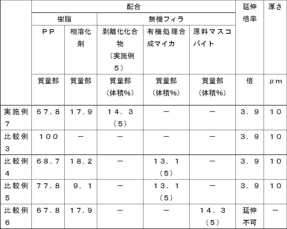
[実施例8]
ポリ容器中にポリプロピレンペレット(FS2011DG3、住友化学株式会社製)74.3質量部、相溶化剤として無水マレイン酸変性ポリプロピレン粒(ユーメックス1010、比重0.95、三洋化成工業株式会社製)19.6質量部及び無機フィラとして実施例5(96時間)で得られた剥離化化合物(c軸方向の厚さ32nm、平均粒子径4.35μm)6.1質量部を加え、振とう撹拌した混合物を2軸混練押出機(ラボプラストミル10C100/2D15W型、東洋精機株式会社製)に投入し、ロータ回転数300rpm(min-1)、設定温度230℃で、Tダイノズルを用いて押出成形し、厚さ40μm~60μmのシート状試料を得た。ここで、相溶化剤の含有率は樹脂成分(無機フィラを除く)に対する仕込み体積分率で20体積%に相当し、無機フィラ含有率は混合物全量に対する仕込み体積分率で2体積%に相当する。次に、このシート状試料を40mm角に切り出し、2軸延伸装置(IMC-18B2C-1型、株式会社井元製作所製)を用いて、設定温度140℃、延伸速度120mm/分で押出し長手方向に3.9倍に延伸し、厚さ10μmのフィルム状試料を得た。
得られたフィルム状試料について、25℃及び85℃での絶縁破壊強度を、後述の方法により測定した結果をワイブルプロットしたところ、図10に示す結果であった。
ポリ容器中にポリプロピレンペレット(FS2011DG3、住友化学株式会社製)74.3質量部、相溶化剤として無水マレイン酸変性ポリプロピレン粒(ユーメックス1010、比重0.95、三洋化成工業株式会社製)19.6質量部及び無機フィラとして実施例5(96時間)で得られた剥離化化合物(c軸方向の厚さ32nm、平均粒子径4.35μm)6.1質量部を加え、振とう撹拌した混合物を2軸混練押出機(ラボプラストミル10C100/2D15W型、東洋精機株式会社製)に投入し、ロータ回転数300rpm(min-1)、設定温度230℃で、Tダイノズルを用いて押出成形し、厚さ40μm~60μmのシート状試料を得た。ここで、相溶化剤の含有率は樹脂成分(無機フィラを除く)に対する仕込み体積分率で20体積%に相当し、無機フィラ含有率は混合物全量に対する仕込み体積分率で2体積%に相当する。次に、このシート状試料を40mm角に切り出し、2軸延伸装置(IMC-18B2C-1型、株式会社井元製作所製)を用いて、設定温度140℃、延伸速度120mm/分で押出し長手方向に3.9倍に延伸し、厚さ10μmのフィルム状試料を得た。
得られたフィルム状試料について、25℃及び85℃での絶縁破壊強度を、後述の方法により測定した結果をワイブルプロットしたところ、図10に示す結果であった。
(絶縁破壊強度の測定方法)
平板状電極(下部電極)と測定対象との接触部分の直径が20mmの円筒電極(上部電極)でフィルム状試料をはさみ、油中に浸した状態で、所定の温度に設定した恒温槽に入れた。ファンクションジェネレータ(SG-4104型、岩通計測株式会社製)より昇圧速度一定の直流電圧を出力し、高圧アンプ(10/40A-HS型、トレック・ジャパン株式会社製)を用いて増幅した直流電圧を上下電極間に印加し、昇圧速度500V/sで絶縁破壊するまで通電した。上記高圧アンプからの電圧値及び電流値の出力をデータロガー(GL200A型、グラフテック株式会社製)を用いて記録し、絶縁破壊した時の電圧値を読み取り、絶縁破壊電圧(BDV:Break Down Voltage)とした。絶縁破壊電圧を試料厚さ(μm)で除算することにより、絶縁破壊強度(BDS:Break Down Strength)(V/μm)を求めた。
平板状電極(下部電極)と測定対象との接触部分の直径が20mmの円筒電極(上部電極)でフィルム状試料をはさみ、油中に浸した状態で、所定の温度に設定した恒温槽に入れた。ファンクションジェネレータ(SG-4104型、岩通計測株式会社製)より昇圧速度一定の直流電圧を出力し、高圧アンプ(10/40A-HS型、トレック・ジャパン株式会社製)を用いて増幅した直流電圧を上下電極間に印加し、昇圧速度500V/sで絶縁破壊するまで通電した。上記高圧アンプからの電圧値及び電流値の出力をデータロガー(GL200A型、グラフテック株式会社製)を用いて記録し、絶縁破壊した時の電圧値を読み取り、絶縁破壊電圧(BDV:Break Down Voltage)とした。絶縁破壊電圧を試料厚さ(μm)で除算することにより、絶縁破壊強度(BDS:Break Down Strength)(V/μm)を求めた。
[比較例7]
比較例3と同一の材料、加工条件でフィルム状試料を得た。得られたフィルム状試料について、25℃及び85℃での絶縁破壊強度を、前述の方法により測定した結果をワイブルプロットしたところ、図10に示す結果であった。
比較例3と同一の材料、加工条件でフィルム状試料を得た。得られたフィルム状試料について、25℃及び85℃での絶縁破壊強度を、前述の方法により測定した結果をワイブルプロットしたところ、図10に示す結果であった。
実施例8、及び比較例7の試料諸元と、絶縁破壊強度の測定結果のまとめを表3に示す。ここで、絶縁破壊に寄与する試料内部の欠陥が多いほどデータがばらつき、ワイブルプロットの回帰直線の傾きは小さくなると考えられるため、回帰直線の傾きが大きいほど欠陥の少ない絶縁特性の優れた材料だと考えられる。また、回帰直線における累積確率63.2%の絶縁破壊強度(尺度パラメータ)をその試料の絶縁耐圧(V/μm)と定義した。

図10及び表3より、実施例8は、比較例7に比べて、高温(85℃)での絶縁耐圧、回帰直線の傾き共に高い値を示し、絶縁耐圧の室温(25℃)から高温(85℃)への低下率も低いことから、特定剥離化化合物の添加により、絶縁性樹脂組成物及び樹脂フィルムの高温化における耐絶縁破壊特性が優れることがわかる。
2015年3月5日に出願された日本国特許出願2015-43960号の開示は、その全体が参照により本明細書に取り込まれる。
本明細書に記載された全ての文献、特許出願、及び技術規格は、個々の文献、特許出願、及び技術規格が参照により取り込まれることが具体的かつ個々に記された場合と同程度に、本明細書中に参照により取り込まれる。
本明細書に記載された全ての文献、特許出願、及び技術規格は、個々の文献、特許出願、及び技術規格が参照により取り込まれることが具体的かつ個々に記された場合と同程度に、本明細書中に参照により取り込まれる。
Claims (5)
- 熱可塑性樹脂と無機フィラとを含有し、前記無機フィラの少なくとも一部が、c軸方向の平均粒子厚さが1nm~80nmである剥離化された層状無機化合物である絶縁性樹脂組成物。
- 前記剥離化された層状無機化合物の含有率が、1体積%~10体積%である請求項1に記載の絶縁性樹脂組成物。
- 請求項1又は請求項2に記載の絶縁性樹脂組成物をシート状に成形してなる樹脂シート。
- 請求項1又は請求項2に記載の絶縁性樹脂組成物をフィルム状に成形してなる樹脂フィルム。
- 請求項1又は請求項2に記載の絶縁性樹脂組成物の成形物である絶縁物。
Priority Applications (1)
| Application Number | Priority Date | Filing Date | Title |
|---|---|---|---|
| JP2017503720A JP6814423B2 (ja) | 2015-03-05 | 2016-03-03 | 絶縁性樹脂組成物、樹脂シート、樹脂フィルム及び絶縁物 |
Applications Claiming Priority (2)
| Application Number | Priority Date | Filing Date | Title |
|---|---|---|---|
| JP2015043960 | 2015-03-05 | ||
| JP2015-043960 | 2015-03-05 |
Publications (1)
| Publication Number | Publication Date |
|---|---|
| WO2016140329A1 true WO2016140329A1 (ja) | 2016-09-09 |
Family
ID=56848495
Family Applications (1)
| Application Number | Title | Priority Date | Filing Date |
|---|---|---|---|
| PCT/JP2016/056669 Ceased WO2016140329A1 (ja) | 2015-03-05 | 2016-03-03 | 絶縁性樹脂組成物、樹脂シート、樹脂フィルム及び絶縁物 |
Country Status (3)
| Country | Link |
|---|---|
| JP (1) | JP6814423B2 (ja) |
| TW (1) | TW201641607A (ja) |
| WO (1) | WO2016140329A1 (ja) |
Citations (2)
| Publication number | Priority date | Publication date | Assignee | Title |
|---|---|---|---|---|
| JPH02504089A (ja) * | 1987-07-10 | 1990-11-22 | レイケム・リミテッド | ワイヤー |
| JP2003026939A (ja) * | 2000-12-08 | 2003-01-29 | Sekisui Chem Co Ltd | 絶縁基板用材料、プリント基板、積層板、樹脂付き銅箔、銅張積層板、ポリイミドフィルム、tab用フィルム及びプリプレグ |
-
2016
- 2016-03-03 WO PCT/JP2016/056669 patent/WO2016140329A1/ja not_active Ceased
- 2016-03-03 JP JP2017503720A patent/JP6814423B2/ja not_active Expired - Fee Related
- 2016-03-04 TW TW105106769A patent/TW201641607A/zh unknown
Patent Citations (2)
| Publication number | Priority date | Publication date | Assignee | Title |
|---|---|---|---|---|
| JPH02504089A (ja) * | 1987-07-10 | 1990-11-22 | レイケム・リミテッド | ワイヤー |
| JP2003026939A (ja) * | 2000-12-08 | 2003-01-29 | Sekisui Chem Co Ltd | 絶縁基板用材料、プリント基板、積層板、樹脂付き銅箔、銅張積層板、ポリイミドフィルム、tab用フィルム及びプリプレグ |
Also Published As
| Publication number | Publication date |
|---|---|
| JPWO2016140329A1 (ja) | 2018-03-01 |
| JP6814423B2 (ja) | 2021-01-20 |
| TW201641607A (zh) | 2016-12-01 |
Similar Documents
| Publication | Publication Date | Title |
|---|---|---|
| Ding et al. | Anisotropic thermal conductive properties of hot-pressed polystyrene/graphene composites in the through-plane and in-plane directions | |
| Huang et al. | Boron nitride@ graphene oxide hybrids for epoxy composites with enhanced thermal conductivity | |
| Konishi et al. | Nanoparticle induced network self-assembly in polymer–carbon black composites | |
| El Achaby et al. | Mechanical, thermal, and rheological properties of graphene‐based polypropylene nanocomposites prepared by melt mixing | |
| Wakabayashi et al. | Polypropylene-graphite nanocomposites made by solid-state shear pulverization: Effects of significantly exfoliated, unmodified graphite content on physical, mechanical and electrical properties | |
| Shtein et al. | Thermally conductive graphene-polymer composites: size, percolation, and synergy effects | |
| Wei et al. | Fabrication of a high-density polyethylene/graphene composite with high exfoliation and high mechanical performance via solid-state shear milling | |
| Su et al. | Synergistic enhancement of anisotropic thermal transport flexible polymer composites filled with multi-layer graphene (mG) and mussel-inspiring modified hexagonal boron nitride (h-BN) | |
| El Achaby et al. | Preparation and characterization of melt‐blended graphene nanosheets–poly (vinylidene fluoride) nanocomposites with enhanced properties | |
| Ahn et al. | Thermal conductivity of polymer composites with oriented boron nitride | |
| Li et al. | Towards suppressing loss tangent: Effect of polydopamine coating layers on dielectric properties of core–shell barium titanate filled polyvinylidene fluoride composites | |
| Kong et al. | Improvement in mechanical and thermal properties of polypropylene nanocomposites using an extremely small amount of alkyl chain-grafted hexagonal boron nitride nanosheets | |
| Cerezo et al. | Structural, mechanical and dielectric properties of poly (ethylene-co-methyl acrylate-co-acrylic acid) graphite oxide nanocomposites | |
| Zhang et al. | Linear and ferroelectric effects of BaTiO3 particle size on the energy storage performance of composite films with different polymer matrices | |
| Al-Saleh et al. | Graphene nanoplatelet–polystyrene nanocomposite: dielectric and charge storage behaviors | |
| Lakshmi et al. | Giant permittivity of three phase polymer nanocomposites obtained by modifying hybrid nanofillers with polyvinylpyrrolidone | |
| Hu et al. | Improved dielectric properties of polypropylene-based nanocomposites via co-filling with zinc oxide and barium titanate | |
| Helal et al. | Styrenic block copolymer-based nanocomposites: Implications of nanostructuration and nanofiller tailored dispersion on the dielectric properties | |
| Aram et al. | Functionalization of graphene nanosheets and its dispersion in PMMA/PEO blend: Thermal, electrical, morphological and rheological analyses | |
| Zazoum et al. | LDPE/HDPE/clay nanocomposites: Effects of compatibilizer on the structure and dielectric response | |
| Wang et al. | Poly (sodium 4-styrenesulfonate) modified graphene for reinforced biodegradable poly (ε-caprolactone) nanocomposites | |
| Zeng et al. | Improved dielectric and mechanical properties of Ti3C2Tx MXene/silicone rubber composites achieved by adding a few boron nitride nanoplates | |
| Wu et al. | Effect of solid-state shear milling on the physicochemical properties of thermally conductive low-temperature expandable graphite/low-density polyethylene composites | |
| JP6664743B2 (ja) | 層状無機化合物と有機化合物との複合体及びその製造方法、剥離化された層状無機化合物及びその製造方法、絶縁性樹脂組成物、樹脂シート、絶縁物、樹脂シート硬化物並びに放熱部材 | |
| Navik et al. | Green approach toward in situ exfoliation and enhanced compatibility to obtain highly conductive polypropylene/graphene composites |
Legal Events
| Date | Code | Title | Description |
|---|---|---|---|
| 121 | Ep: the epo has been informed by wipo that ep was designated in this application |
Ref document number: 16759021 Country of ref document: EP Kind code of ref document: A1 |
|
| ENP | Entry into the national phase |
Ref document number: 2017503720 Country of ref document: JP Kind code of ref document: A |
|
| NENP | Non-entry into the national phase |
Ref country code: DE |
|
| 122 | Ep: pct application non-entry in european phase |
Ref document number: 16759021 Country of ref document: EP Kind code of ref document: A1 |