WO2016139843A1 - 入力装置および入力方法 - Google Patents
入力装置および入力方法 Download PDFInfo
- Publication number
- WO2016139843A1 WO2016139843A1 PCT/JP2015/080575 JP2015080575W WO2016139843A1 WO 2016139843 A1 WO2016139843 A1 WO 2016139843A1 JP 2015080575 W JP2015080575 W JP 2015080575W WO 2016139843 A1 WO2016139843 A1 WO 2016139843A1
- Authority
- WO
- WIPO (PCT)
- Prior art keywords
- unit
- touch panel
- input device
- regions
- contact
- Prior art date
- Legal status (The legal status is an assumption and is not a legal conclusion. Google has not performed a legal analysis and makes no representation as to the accuracy of the status listed.)
- Ceased
Links
Images

Classifications
-
- G—PHYSICS
- G06—COMPUTING OR CALCULATING; COUNTING
- G06F—ELECTRIC DIGITAL DATA PROCESSING
- G06F3/00—Input arrangements for transferring data to be processed into a form capable of being handled by the computer; Output arrangements for transferring data from processing unit to output unit, e.g. interface arrangements
- G06F3/01—Input arrangements or combined input and output arrangements for interaction between user and computer
- G06F3/03—Arrangements for converting the position or the displacement of a member into a coded form
- G06F3/033—Pointing devices displaced or positioned by the user, e.g. mice, trackballs, pens or joysticks; Accessories therefor
- G06F3/038—Control and interface arrangements therefor, e.g. drivers or device-embedded control circuitry
-
- G—PHYSICS
- G06—COMPUTING OR CALCULATING; COUNTING
- G06F—ELECTRIC DIGITAL DATA PROCESSING
- G06F3/00—Input arrangements for transferring data to be processed into a form capable of being handled by the computer; Output arrangements for transferring data from processing unit to output unit, e.g. interface arrangements
- G06F3/01—Input arrangements or combined input and output arrangements for interaction between user and computer
- G06F3/03—Arrangements for converting the position or the displacement of a member into a coded form
- G06F3/0304—Detection arrangements using opto-electronic means
-
- G—PHYSICS
- G06—COMPUTING OR CALCULATING; COUNTING
- G06F—ELECTRIC DIGITAL DATA PROCESSING
- G06F3/00—Input arrangements for transferring data to be processed into a form capable of being handled by the computer; Output arrangements for transferring data from processing unit to output unit, e.g. interface arrangements
- G06F3/01—Input arrangements or combined input and output arrangements for interaction between user and computer
- G06F3/03—Arrangements for converting the position or the displacement of a member into a coded form
- G06F3/033—Pointing devices displaced or positioned by the user, e.g. mice, trackballs, pens or joysticks; Accessories therefor
- G06F3/0354—Pointing devices displaced or positioned by the user, e.g. mice, trackballs, pens or joysticks; Accessories therefor with detection of two-dimensional [2D] relative movements between the device, or an operating part thereof, and a plane or surface, e.g. 2D mice, trackballs, pens or pucks
- G06F3/03545—Pens or stylus
-
- G—PHYSICS
- G06—COMPUTING OR CALCULATING; COUNTING
- G06F—ELECTRIC DIGITAL DATA PROCESSING
- G06F3/00—Input arrangements for transferring data to be processed into a form capable of being handled by the computer; Output arrangements for transferring data from processing unit to output unit, e.g. interface arrangements
- G06F3/01—Input arrangements or combined input and output arrangements for interaction between user and computer
- G06F3/03—Arrangements for converting the position or the displacement of a member into a coded form
- G06F3/041—Digitisers, e.g. for touch screens or touch pads, characterised by the transducing means
-
- G—PHYSICS
- G06—COMPUTING OR CALCULATING; COUNTING
- G06F—ELECTRIC DIGITAL DATA PROCESSING
- G06F3/00—Input arrangements for transferring data to be processed into a form capable of being handled by the computer; Output arrangements for transferring data from processing unit to output unit, e.g. interface arrangements
- G06F3/01—Input arrangements or combined input and output arrangements for interaction between user and computer
- G06F3/048—Interaction techniques based on graphical user interfaces [GUI]
- G06F3/0487—Interaction techniques based on graphical user interfaces [GUI] using specific features provided by the input device, e.g. functions controlled by the rotation of a mouse with dual sensing arrangements, or of the nature of the input device, e.g. tap gestures based on pressure sensed by a digitiser
- G06F3/0488—Interaction techniques based on graphical user interfaces [GUI] using specific features provided by the input device, e.g. functions controlled by the rotation of a mouse with dual sensing arrangements, or of the nature of the input device, e.g. tap gestures based on pressure sensed by a digitiser using a touch-screen or digitiser, e.g. input of commands through traced gestures
-
- G—PHYSICS
- G06—COMPUTING OR CALCULATING; COUNTING
- G06F—ELECTRIC DIGITAL DATA PROCESSING
- G06F3/00—Input arrangements for transferring data to be processed into a form capable of being handled by the computer; Output arrangements for transferring data from processing unit to output unit, e.g. interface arrangements
- G06F3/01—Input arrangements or combined input and output arrangements for interaction between user and computer
- G06F3/048—Interaction techniques based on graphical user interfaces [GUI]
- G06F3/0487—Interaction techniques based on graphical user interfaces [GUI] using specific features provided by the input device, e.g. functions controlled by the rotation of a mouse with dual sensing arrangements, or of the nature of the input device, e.g. tap gestures based on pressure sensed by a digitiser
- G06F3/0488—Interaction techniques based on graphical user interfaces [GUI] using specific features provided by the input device, e.g. functions controlled by the rotation of a mouse with dual sensing arrangements, or of the nature of the input device, e.g. tap gestures based on pressure sensed by a digitiser using a touch-screen or digitiser, e.g. input of commands through traced gestures
- G06F3/04883—Interaction techniques based on graphical user interfaces [GUI] using specific features provided by the input device, e.g. functions controlled by the rotation of a mouse with dual sensing arrangements, or of the nature of the input device, e.g. tap gestures based on pressure sensed by a digitiser using a touch-screen or digitiser, e.g. input of commands through traced gestures for inputting data by handwriting, e.g. gesture or text
-
- G—PHYSICS
- G06—COMPUTING OR CALCULATING; COUNTING
- G06F—ELECTRIC DIGITAL DATA PROCESSING
- G06F2203/00—Indexing scheme relating to G06F3/00 - G06F3/048
- G06F2203/041—Indexing scheme relating to G06F3/041 - G06F3/045
- G06F2203/04104—Multi-touch detection in digitiser, i.e. details about the simultaneous detection of a plurality of touching locations, e.g. multiple fingers or pen and finger
-
- G—PHYSICS
- G06—COMPUTING OR CALCULATING; COUNTING
- G06F—ELECTRIC DIGITAL DATA PROCESSING
- G06F2203/00—Indexing scheme relating to G06F3/00 - G06F3/048
- G06F2203/048—Indexing scheme relating to G06F3/048
- G06F2203/04806—Zoom, i.e. interaction techniques or interactors for controlling the zooming operation
-
- G—PHYSICS
- G06—COMPUTING OR CALCULATING; COUNTING
- G06F—ELECTRIC DIGITAL DATA PROCESSING
- G06F2203/00—Indexing scheme relating to G06F3/00 - G06F3/048
- G06F2203/048—Indexing scheme relating to G06F3/048
- G06F2203/04808—Several contacts: gestures triggering a specific function, e.g. scrolling, zooming, right-click, when the user establishes several contacts with the surface simultaneously; e.g. using several fingers or a combination of fingers and pen
-
- G—PHYSICS
- G06—COMPUTING OR CALCULATING; COUNTING
- G06F—ELECTRIC DIGITAL DATA PROCESSING
- G06F3/00—Input arrangements for transferring data to be processed into a form capable of being handled by the computer; Output arrangements for transferring data from processing unit to output unit, e.g. interface arrangements
- G06F3/01—Input arrangements or combined input and output arrangements for interaction between user and computer
- G06F3/048—Interaction techniques based on graphical user interfaces [GUI]
- G06F3/0484—Interaction techniques based on graphical user interfaces [GUI] for the control of specific functions or operations, e.g. selecting or manipulating an object, an image or a displayed text element, setting a parameter value or selecting a range
- G06F3/04845—Interaction techniques based on graphical user interfaces [GUI] for the control of specific functions or operations, e.g. selecting or manipulating an object, an image or a displayed text element, setting a parameter value or selecting a range for image manipulation, e.g. dragging, rotation, expansion or change of colour
Definitions
- the present invention relates to an input device and an input method for operating a touch panel.
- touch panel displays Many electronic devices such as smartphones, tablets, car navigation devices, and portable game machines are equipped with touch panel displays.
- the touch panel is often directly operated with a finger, but may be operated with a stylus pen. When a stylus pen is used, finer pointing is possible than with a finger.
- the touch panel surface can be prevented from being stained with fingerprints.
- Patent Document 1 provides a pen with a plurality of buttons, and sends a control signal corresponding to each button being pressed to a device on which the touch panel is mounted, and the device on which the touch panel is mounted responds to the control signal.
- the technology which operates is disclosed.
- pinch-out operation to move the touch position outward to widen the distance between the two points, or to narrow the distance between the two points after touching the two points.
- pinch-in operation that moves the touch position inward.
- the pinch-out operation is used for an enlargement operation
- the pinch-in operation is used for a reduction operation.
- Such a multi-touch gesture that requires touching a plurality of points on the touch panel at the same time basically needs to be performed with a plurality of fingers, and is difficult to perform with a single stylus pen. Therefore, when performing multi-touch gestures when the user is operating using the stylus pen, stop using the stylus pen, perform multi-touch gestures with your finger, and start using the stylus pen again. It is inconvenient.
- the present invention has been made in view of such circumstances, and an object of the present invention is to provide a technique for performing an operation corresponding to a multi-touch gesture with a touch panel other than a finger.
- an input device (1) includes a contact unit (10) having a plurality of regions that can independently stimulate the surface of the touch panel, and an operation operated by a user.
- Unit (22, 23) and a control unit (30) for individually controlling the states of the plurality of regions based on previously stored stimulation patterns when the operation unit (22, 23) is operated. .
- This method is an input method using an input device (1) including a contact unit (10) and an operation unit (22, 23), and accepts a user operation on the operation unit (22, 23); Upon receiving a user's operation, a step of individually controlling the states of a plurality of areas formed on the contact portion (10) capable of stimulating the surface of the touch panel independently based on a previously stored stimulation pattern; Prepare.
- any combination of the above-described constituent elements and a representation of the present embodiment converted between a method, an apparatus, a system, a recording medium, a computer program, etc. are also effective as an aspect of the present embodiment.
- an operation corresponding to the multi-touch gesture can be easily performed on the touch panel other than a finger.
- FIGS. 3A and 3B are diagrams showing how the control unit controls the plurality of areas of the contact unit when the enlarge button is pressed by the user.
- 4A and 4B are diagrams illustrating an example of a state transition pattern before and after the sensitivity change. It is a flowchart which shows the flow of operation
- FIG. 1 is a diagram showing an external configuration of a pen-type input device 1 according to an embodiment of the present invention.
- the input device 1 is a pointing device for operating a touch panel such as a smartphone, a tablet, a car navigation device, or a portable game machine.
- touch panel systems including a resistive film system, a capacitive system, an electromagnetic induction system, a surface acoustic wave system, and an infrared system.
- a surface type and a projection type in the electrostatic capacity method are examples of the electrostatic capacity method.
- a projected capacitive touch panel is configured by laminating a substrate layer on which a control IC is mounted, a transparent electrode layer, and a protective film.
- the substrate layer is formed of a transparent member such as glass or plastic.
- the electrode layer is formed by laminating a horizontal electrode layer in which a plurality of transparent electrodes are arranged in the horizontal direction and a horizontal electrode layer in which a plurality of transparent electrodes are arranged in the vertical direction to form a mosaic electrode pattern.
- the transparent electrode can be made of, for example, ITO (Indium Tin Oxide).
- the control IC can detect the touch position by monitoring the voltage of each electrode.
- the enlarging operation is transmitted to the touch panel side by a pinch out gesture. Further, when the screen displayed in the touch panel display is reduced, the reduction operation is transmitted to the touch panel side by a pinch gesture.
- These gestures are all multi-touch gestures, and the touch panel side needs to be a touch panel capable of detecting multiple points. For example, multipoint detection is difficult with the surface-capacitance method, surface acoustic wave method, and infrared method.
- a contact portion 10 is formed at the tip of the input device 1 according to the present embodiment.
- the first operation unit 21, the second operation unit 22, the third operation unit 23, and the photographing unit 70 are attached to the body of the input device 1.
- the first operation unit 21 is a power button
- the second operation unit 22 is an enlargement button
- the third operation unit 23 is a reduction button.
- the attachment positions of the first operation unit 21, the second operation unit 22, the third operation unit 23, and the photographing unit 70 shown in FIG. 1 are arbitrary and can be changed as appropriate. For example, you may attach the imaging
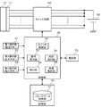
- FIG. 2 is a diagram showing an internal system configuration of the input device 1 of FIG.
- the input device 1 includes a power supply unit 50.
- the power supply unit 50 includes a small battery such as an AAA battery or a button battery.
- the battery may be a storage battery that can be charged from the outside.
- the contact portion 10 has a plurality of regions that can independently stimulate the surface of the touch panel. In this embodiment, since the electrostatic capacitance method is used, electrical stimulation is given to the surface of the touch panel.
- the plurality of regions are formed by dividing the front end surface of the input device 1 into a plurality of blocks in a matrix. Insulating members are respectively inserted at boundaries between adjacent blocks, and adjacent blocks are insulated from each other.
- Electrode members are disposed in the respective regions constituting the contact unit 10, and each electrode member is connected to the power supply unit 50 (the positive electrode of the battery in FIG. 2) via the switch circuit 60.
- An insulating member 11 is formed on the back surface of the contact portion 10 to prevent the electrode members of the contact portion 10 and the main body of the input device 1 from being electrically coupled except for the wiring.
- the switch circuit 60 includes a plurality of switches respectively inserted between a plurality of wires connecting the electrode members of the contact portion 10 and the power source portion 50 respectively.
- a MOSFET, IGBT, relay, or the like can be used as the switch.
- the plurality of switches are individually turned on / off, whereby the state of each electrode member of the contact portion 10 is individually controlled. When the switch is turned on, the electrode member is in a conductive state, and when the switch is turned off, the electrode member is in an insulated state.
- the first operation unit 21, the second operation unit 22, and the third operation unit 23 output an operation signal to the control unit 30 when operated by the user.
- an on / off signal indicating the pressed state of the button is output to the control unit 30.
- the control unit 30 includes an operation receiving unit 31, a reading unit 32, a switch control unit 33, a photographing control unit 34, and an image analysis unit 35.
- an operation receiving unit 31 a reading unit 32, a switch control unit 33, a photographing control unit 34, and an image analysis unit 35.
- the function of the control unit 30 can be realized by cooperation of hardware resources and software resources, or only by hardware resources. Processors, ROM, RAM, and other LSIs can be used as hardware resources. Firmware and other programs can be used as software resources.
- the storage unit 40 includes a storage medium such as a nonvolatile semiconductor memory.
- the storage unit 40 includes a pattern data holding unit 41. Also in the functional blocks of the storage unit 40 in FIG. 2, only functional blocks related to the process of interest in the present embodiment are drawn.
- the pattern data holding unit 41 holds in advance pattern data describing state transition patterns of a plurality of regions of the contact unit 10 corresponding to the trajectory of the multi-touch gesture. That is, the pattern data is time-series data describing which region is to be conductive in each period.
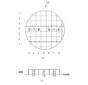
- FIG. 3A and 3B are diagrams for explaining the surface of the contact portion 10 and the pinch-out pattern.
- the surface of the contact portion 10 is divided into blocks in a matrix. Each area divided into blocks is designated by a combination of an X-direction address (AG) and a Y-direction address (1-7).
- control unit 30 individually controls whether each region is in a conductive state or an insulating state. Specifically, the control unit 30 controls a region where the surface of the touch panel should be electrically stimulated among the plurality of regions of the contact unit 10 to be in a conductive state, and a region where the surface of the touch panel should not be stimulated electrically. Control to insulation. The region to be electrically stimulated corresponds to the region of the position where the control circuit of the touch panel is determined to be touch.
- 3 (a) and 3 (b) are diagrams showing how the control unit 30 controls the plurality of areas of the contact unit 10 when the enlarge button is pressed by the user.
- the control unit 30 energizes the electrode members in the regions C4 and E4 to be in a conductive state, and does not energize electrode members in other regions to be in an insulated state.
- the electrode members in the regions B4 and F4 are energized to be in a conductive state, and the electrode members in other regions are not energized to be in an insulated state.
- the electrode members in the regions A4 and G4 are energized to be in a conductive state, and the electrode members in other regions are not energized to be in an insulated state.
- the electrode of the touch panel capacitively coupled with the contact portion 10 of the input device 1 changes in the direction of the arrow as time passes. Thereby, it can be recognized that a pinch-out gesture has been made to the control circuit of the touch panel.
- the control unit 30 controls the state of the plurality of areas of the contact unit 10 according to the pinch-in pattern opposite to the pinch-out pattern described above.
- the entire region of the contact portion 10 is controlled to be in a conductive state. This causes the touch panel control circuit to recognize it as a single touch. Note that it is not always necessary to control all the regions to be in a conductive state as long as the regions controlled to be in a conductive state are solidified into one.
- the operation receiving unit 31 of the control unit 30 is operated when any one of the first operation unit 21 (power button), the second operation unit 22 (enlarge button), and the third operation unit 23 (reduction button) is operated by the user.
- An operation signal is received from the corresponding operation unit.
- the reading unit 32 reads pattern data corresponding to the operation signal from the pattern data holding unit 41. For example, when the enlarge button is pressed, the pattern data for pinch out is read from the pattern data holding unit 41. When the reduction button is pressed, pinch-in pattern data is read from the pattern data holding unit 41.
- the switch control unit 33 controls the switch circuit 60 based on the read pattern data. Since the switch circuit 60 includes a switch for each wiring connected to a plurality of regions of the contact portion 10, each region can be individually switched between a conductive state and an insulating state.
- the displacement of the conductive position based on the pattern data may be too fast or too slow to be recognized as a specific multi-touch gesture by the touch panel control circuit.
- the configuration and processing corresponding to this will be described.
- the configuration and processing described below are optional and are not essential elements of the input device 1 according to the present embodiment.
- the camera unit 70 is attached to the input device 1. Specifically, a small camera is attached to the tip or clip of the input device 1. The camera is attached to a position and an orientation in which the surface of the touch panel with which the contact unit 10 comes into contact (a display unit of a device including the touch panel) can be captured. A camera equipped with a moving image mode or a continuous shooting mode is used as the camera.
- the imaging unit 70 includes a solid-state imaging device such as a CCD image sensor or a CMOS image sensor, and a signal processing circuit that processes a signal output from the solid-state imaging device.
- a signal processing circuit for example, signal processing such as noise removal and A / D conversion is performed.
- the imaging unit 70 outputs the captured image to the control unit 30.
- the shooting control unit 34 instructs the shooting unit 70 to start shooting when the second operation unit 22 (enlarge button) or the third operation unit 23 (reduction button) is operated by the user.
- the photographing unit 70 starts moving image shooting or continuous shooting. These processes are performed before a series of control for a plurality of regions of the contact unit 10 based on the pattern data by the switch control unit 33 is started.
- the imaging control unit 34 instructs the imaging unit 70 to end imaging.
- the photographing unit 70 ends the moving image photographing or the continuous photographing.
- the image analysis unit 35 analyzes the touch panel image shot by the shooting unit 70 after the above-described series of control ends. Specifically, an image taken before the above-described series of control is started and an image taken after the series of control are finished are compared. The image analysis unit 35 compares both images and determines whether processing based on the operation content instructed from the input device 1 on the touch panel side has been executed.
- the image analysis unit 35 uses, for example, an existing object detection algorithm to detect an object in an image photographed before the above-described series of controls is started. For example, a character string in the image is detected as an object. The image analysis unit 35 generates a classifier for the detected object. The image analysis unit 35 searches for the object while enlarging or reducing the classifier in the image taken after the above-described series of control is completed.
- the image analysis unit 35 determines the size of the object detected in the image taken after the above series of control is completed, and processing based on the enlargement operation or reduction operation instructed from the input device 1 is performed on the touch panel side. It is determined whether it has been executed. When the instructed operation is not executed, the reading unit 32 reads pattern data describing state transition patterns having different sensitivities for realizing the same multi-touch gesture from the pattern data holding unit 41. The switch control unit 33 controls the switch circuit 60 based on the read pattern data.
- the state transition patterns having different sensitivities are, for example, patterns in which the time interval at which the conductive position is displaced is changed. A pattern in which the range of the unit area is changed may be used.
- a block composed of a plurality of adjacent areas (for example, 4 areas and 9 areas) is handled as a unit area.
- a plurality of areas in one block are controlled to all the same state. This example corresponds to changing the size of the pen tip.
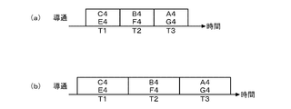
- FIGS. 4A and 4B are diagrams showing an example of a state transition pattern before and after the sensitivity change.
- the state transition pattern in FIG. 4A corresponds to the state transition pattern in FIG.
- the state transition pattern in FIG. 4B is an example in which the time interval at which the conductive position of the state transition pattern in FIG.
- the touch position may not be fully tracked. In this case, the possibility that the control circuit of the touch panel can follow the touch position increases by increasing the time interval at which the conductive position is displaced. Note that even in the control based on the state transition pattern in FIG. 4A, if the instructed operation is not performed on the touch panel side, retry may be performed based on the state transition pattern in which the time interval at which the conductive position is displaced is further widened. .
- the displacement speed of the conductive position is too slow for the touch panel control circuit, it may not be recognized as a series of gestures.
- the possibility that the control circuit of the touch panel recognizes as a series of gestures is increased by narrowing the time interval at which the conductive position is displaced.
- the control may be retried based on the state transition pattern in which the time interval at which the conductive position is displaced is narrowed.
- retry based on the state transition pattern in which the time interval at which the conductive position is displaced is widened and retry based on the state transition pattern in which the time interval at which the conductive position is displaced are narrowed may be performed alternately.
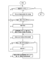
- FIG. 5 is a flowchart showing a flow of operations of the input apparatus 1 according to the embodiment of the present invention.
- the operation reception unit 31 receives an operation signal from the first operation unit 21 (power button).
- the switch control unit 33 controls the switch circuit 60 to control the fixed region in the contact unit 10 to the conductive state (S11).
- the imaging control unit 34 becomes an operation target for the imaging unit 70. Touch panel shooting is started (S13).
- the switch control unit 33 controls the switch circuit 60 based on the state transition pattern of the corresponding operation to control the state of the plurality of regions of the contact unit 10 (S14).
- the image analysis unit 35 analyzes the touch panel image before the start of the control and the touch panel image after the end of the control (S15). As a result of the image analysis, when it is determined that the enlargement / reduction operation is successful (Y in S17), the imaging control unit 34 causes the imaging unit 70 to end imaging of the touch panel (S18). Then, the process proceeds to step S10. If the power-off state is instructed in step S10 (N in S10), the entire process is terminated.
- the switch control unit 33 controls the switch circuit 60 based on the state transition patterns having different sensitivities, and the contact unit 10 The states of the plurality of regions are controlled (S18). Thereafter, the process proceeds to step S15, and the processes after step S16 are repeated.
- the processes in steps S13 and S15 to S18 are not necessary.
- the process shown in FIG. 5 may be executed a plurality of times by pressing the enlargement button a plurality of times.
- the process shown in FIG. 5 may be executed a plurality of times by pressing the reduction button a plurality of times.
- a plurality of pinch-out / in patterns may be prepared, and the pattern to be used may be selected according to the time for pressing the enlarge / reduce button.
- a plurality of patterns having different trajectories may be prepared.
- the user can simply perform an operation corresponding to the multi-touch gesture by simply pressing the operation button of the pen-type input device 1 on the touch panel.
- it is confirmed whether or not the operation content instructed by the multi-touch gesture is installed on the touch panel side by installing the photographing unit 70, and if it is not executed, retry with a state transition pattern having a different sensitivity.
- it can be used with high sensitivity on various types of touch panels.
- the multi-touch gesture on the slight contact surface of the pen tip is more likely to occur when the touch panel device does not recognize the multi-touch gesture as compared with the operation with the finger.
- the main factors are that the transition of the touch position is small and the contact area of the touch position tends to be small.
- a function of determining whether the device on the touch panel side is touched with a finger or operated with the pen-type input device 1 may be installed.
- each threshold value used when determining the multi-touch gesture may be changed to a threshold value suitable for touch detection by the pen-type input device 1.
- the input device to which the present invention is applied is not limited to a pen-type, for example, applied to a finger portion of a glove. Also good.
- the input device 1 may be configured as follows.
- a drive mechanism is provided that can physically move each region of the contact portion 10 up and down individually in the pen axis direction.
- the control unit 30 controls the drive mechanism based on pattern data describing physical state transitions of a plurality of regions of the contact unit 10. In this way, a multi-touch gesture can be realized by physically stimulating the surface of the touch panel rather than electrically stimulating it.
- the resistance value of the portion that receives physical stimulation changes, so that the device on the touch panel side can detect the touch position.
- the capacitance value between the two is changed by individually adjusting the distance between the electrode layer of the touch panel and each electrode member of the contact portion 10 by the drive mechanism, not the switch circuit 60. You may let them.
- a coil may be provided in each region of the contact portion 10 and the energization state of each coil may be individually controlled.
- the present invention can be used for an input device for a touch panel.
Landscapes
- Engineering & Computer Science (AREA)
- General Engineering & Computer Science (AREA)
- Theoretical Computer Science (AREA)
- Human Computer Interaction (AREA)
- Physics & Mathematics (AREA)
- General Physics & Mathematics (AREA)
- User Interface Of Digital Computer (AREA)
- Position Input By Displaying (AREA)
Abstract
接触部(10)は、それぞれ独立にタッチパネルの表面を刺激可能な複数の領域を持つ。制御部(30)は、操作部が操作されると、予め記憶された刺激パターンに基づき複数の領域の状態を個別に制御する。刺激パターンは、ピンチアウトジェスチャやピンチインジェスチャ等のマルチタッチジェスチャの軌跡に対応する複数の領域の状態推移パターンを記述している。
Description
本発明は、タッチパネルを操作するための入力装置および入力方法に関する。
スマートフォン、タブレット、カーナビゲーション装置、携帯型ゲーム機などの電子機器の多くはタッチパネルディスプレイを搭載している。タッチパネルは指で直接操作されることが多いが、スタイラスペンで操作される場合もある。スタイラスペンを使用すると、指で操作するより細かなポインティングが可能となる。またタッチパネルの表面が指紋で汚れることを防止できる。
特許文献1は、ペンに複数のボタンを設け、各ボタンが押された際に対応する制御信号を、タッチパネルを搭載する側の機器に送り、タッチパネルを搭載する側の機器はその制御信号に応じて動作する技術を開示している。
タッチパネルの操作の中には、2点をタッチした後に2点間の間隔を広げるようにタッチ位置を外側に移動させるピンチアウト操作や、2点をタッチした後に2点間の間隔を狭めるようにタッチ位置を内側に移動させるピンチイン操作がある。通常、ピンチアウト操作は拡大操作に使用され、ピンチイン操作は縮小操作に使用される。
このようなタッチパネル上の複数の点を同時にタッチする必要があるマルチタッチジェスチャは、基本的に複数の指で行う必要があり、1本のスタイラスペンで行うことは困難である。このため、ユーザがスタイラスペンを使用して操作している場合にマルチタッチジェスチャを行うときは、一旦スタイラスペンの使用を中止し、指でマルチタッチジェスチャを行い、再度、スタイラスペンの使用を開始しなければならず不便である。
本発明はこうした状況に鑑みてなされたものであり、その目的は、タッチパネルに対して指以外で簡便にマルチタッチジェスチャに対応する操作を行う技術を提供することにある。
上記課題を解決するために、本実施形態のある態様の入力装置(1)は、それぞれ独立にタッチパネルの表面を刺激可能な複数の領域を持つ接触部(10)と、ユーザにより操作される操作部(22、23)と、前記操作部(22、23)が操作されると、予め記憶された刺激パターンに基づき前記複数の領域の状態を個別に制御する制御部(30)と、を備える。
本実施形態の別の態様は、入力方法である。この方法は、接触部(10)と操作部(22、23)を備える入力装置(1)を用いた入力方法であって、前記操作部(22、23)に対するユーザの操作を受け付けるステップと、ユーザの操作を受け付けると、予め記憶された刺激パターンに基づき、前記接触部(10)に形成されたそれぞれ独立にタッチパネルの表面を刺激可能な複数の領域の状態を個別に制御するステップと、を備える。
なお、以上の構成要素の任意の組合せ、本実施形態の表現を方法、装置、システム、記録媒体、コンピュータプログラムなどの間で変換したものもまた、本実施形態の態様として有効である。
本実施形態によれば、タッチパネルに対して指以外で簡便にマルチタッチジェスチャに対応する操作を行うことができる。
図1は、本発明の実施の形態に係るペン型の入力装置1の外観構成を示す図である。入力装置1は、スマートフォン、タブレット、カーナビゲーション装置、携帯型ゲーム機などのタッチパネルを操作するためのポインティングデバイスである。タッチパネルの方式には種々あり、抵抗膜方式、静電容量方式、電磁誘導方式、表面弾性波方式、赤外線方式がある。静電容量方式には表面型と投影型がある。
以下、本実施の形態ではマルチタッチに適した投影型静電容量方式を使用する例を説明する。投影型静電容量方式のタッチパネルは、制御ICを搭載する基板層、透明電極層、保護フィルムが積層されて構成される。基板層はガラスやプラスチック等の透明部材で形成される。電極層は、横方向に複数の透明電極を配列した横方向電極層と縦方向に複数の透明電極を配列した横方向電極層が2層重ねられて形成され、モザイク状の電極パターンを構成する。透明電極は例えば、ITO(Indium Tin Oxide)で構成できる。
保護フィルムの上から電極層に、指などの導電体が近づくと両者の間に容量結合が発生する。容量結合が発生した箇所では、近づいた導電体と電極間の容量値が大きくなる。容量値の変化は各電極に電圧変化として現れるため、制御ICは各電極の電圧を監視することにより、タッチ位置を検出できる。
一般にタッチパネルディスプレイ内に表示された画面を拡大するとき、ピンチアウトジェスチャにより拡大操作がタッチパネル側に伝達される。またタッチパネルディスプレイ内に表示された画面を縮小するとき、ピンチインジェスチャにより縮小操作がタッチパネル側に伝達される。これらのジェスチャはいずれもマルチタッチジェスチャであり、タッチパネル側は多点検出可能なタッチパネルである必要がある。例えば、表面型静電容量方式、表面弾性波方式、赤外線方式では多点検出が難しい。
図1に示すように本実施の形態に係る入力装置1の先端には接触部10が形成される。また入力装置1のボディには第1操作部21、第2操作部22、第3操作部23及び撮影部70が取り付けられる。以下の説明では第1操作部21を電源ボタン、第2操作部22を拡大ボタン、第3操作部23を縮小ボタンとする。
図1に示した第1操作部21、第2操作部22、第3操作部23及び撮影部70の取付位置は任意であり、適宜変更が可能である。例えば撮影部70をクリップに取付けてもよい。また、マルチタッチジェスチャで実現される、拡大操作および縮小操作以外の別の操作を実現する操作ボタンをさらに追加してもよい。あるスマートフォン等では、4点または5点をタッチした後にそれらの点を上方に移動させるジェスチャで、マルチタスク表示画面への切替操作としている。この切替操作を実現する操作ボタンを、第2操作部22及び第3操作部23の近傍に追加してもよい。
図2は、図1の入力装置1の内部システム構成を示す図である。入力装置1は電源部50を備える。電源部50は単4乾電池、ボタン電池などの小型の電池を備える。当該電池は外部から充電可能な蓄電池であってもよい。接触部10は、それぞれ独立にタッチパネルの表面を刺激可能な複数の領域を持つ。本実施の形態では静電容量方式を使用しているため、タッチパネルの表面に電気的な刺激を与える。当該複数の領域は例えば、入力装置1の先端面をマトリクス状に複数のブロックに分割して形成される。隣接するブロック間の境界にはそれぞれ絶縁部材が挿入され、隣接するブロック間はそれぞれ絶縁される。
接触部10を構成する各領域にはそれぞれ電極部材が配置され、各電極部材はスイッチ回路60を介して電源部50(図2では電池の正極)にそれぞれ接続される。接触部10の裏面には絶縁部材11が形成され、接触部10の各電極部材と入力装置1の本体が配線以外で電気的に結合することが阻止される。
スイッチ回路60は、接触部10の各電極部材と電源部50をそれぞれ接続する複数の配線間にそれぞれ挿入される複数のスイッチを含む。スイッチは例えば、MOSFET、IGBT、リレー等を用いることができる。この複数のスイッチが個別にオン/オフ制御されることにより、接触部10の各電極部材の状態が個別に制御される。スイッチがオンされた場合は電極部材は導電状態となり、スイッチがオフされた場合は電極部材は絶縁状態となる。
第1操作部21、第2操作部22及び第3操作部23は、ユーザにより操作されると操作信号を制御部30に出力する。ボタンが使用される場合、ボタンの押下状態を示すオン/オフ信号を制御部30に出力する。
制御部30は操作受付部31、読出部32、スイッチ制御部33、撮影制御部34及び画像解析部35を含む。図2の制御部30の機能ブロックには、本実施の形態で注目する処理に関連する機能ブロックのみを描いている。制御部30の機能はハードウェア資源とソフトウェア資源の協働、又はハードウェア資源のみにより実現できる。ハードウェア資源としてプロセッサ、ROM、RAM、その他のLSIを利用できる。ソフトウェア資源としてファームウェア等のプログラムを利用できる。
記憶部40は不揮発性半導体メモリ等の記憶媒体を備える。本実施の形態では記憶部40はパターンデータ保持部41を含む。図2の記憶部40の機能ブロックにも、本実施の形態で注目する処理に関連する機能ブロックのみを描いている。パターンデータ保持部41は、マルチタッチジェスチャの軌跡に対応する、接触部10の複数の領域の状態推移パターンを記述したパターンデータを予め保持している。即ちパターンデータは各期間において、どの領域を導電状態にするかを記述した時系列データである。
図3(a)、(b)は接触部10の表面と、ピンチアウトパターンを説明するための図である。図3(a)では接触部10の表面をマトリクス状にブロック分割している。X方向のアドレス(A-G)とY方向のアドレス(1-7)の組み合わせでブロック分割された各領域が指定される。
本実施の形態では、ユーザが入力装置1の接触部10をタッチパネルに接触させる際、接触部10の各領域がタッチパネルの表面を電気的に刺激するか否かを個別に制御できる。静電容量方式のタッチパネルに使用される本実施の形態に係る入力装置1では、制御部30は各領域を導電状態とするか絶縁状態とするか個別に制御する。具体的には制御部30は、接触部10の複数の領域の内、タッチパネルの表面を電気的に刺激すべき領域を導電状態に制御し、タッチパネルの表面を電気的に刺激すべきでない領域を絶縁状態に制御する。電気的に刺激すべき領域はタッチパネルの制御回路にタッチと判定させたい位置の領域に対応する。
図3(a)、(b)は、ユーザにより拡大ボタンが押下された際の制御部30による接触部10の複数の領域に対する制御の様子を示した図である。制御部30は期間T1において領域C4、E4の電極部材に通電して導電状態とし、他の領域の電極部材には通電せずに絶縁状態とする。次に期間T2において領域B4、F4の電極部材に通電して導電状態とし、他の領域の電極部材には通電せずに絶縁状態とする。次に期間T3において領域A4、G4の電極部材に通電して導電状態とし、他の領域の電極部材には通電せずに絶縁状態とする。これにより入力装置1の接触部10と容量結合する、タッチパネルの電極が時間経過に伴い矢印の方向に変化する。これによりタッチパネルの制御回路にピンチアウトジェスチャがなされたことを認識させることができる。
ユーザにより縮小ボタンが押下された際は、上述のピンチアウトパターンと逆のピンチインパターンに従い制御部30は、接触部10の複数の領域の状態を制御する。ユーザにより拡大ボタンも縮小ボタンが押下されていない通常の状態では、接触部10の全ての領域を導電状態に制御する。これによりタッチパネルの制御回路に、シングルタッチと認識させる。なお導電状態に制御される領域が一つに固まっていれば、必ずしも全ての領域を導電状態に制御する必要はない。
図2に戻る。制御部30の操作受付部31は、ユーザにより第1操作部21(電源ボタン)、第2操作部22(拡大ボタン)、第3操作部23(縮小ボタン)のいずれかが操作された際、該当する操作部から操作信号を受け付ける。読出部32は、操作信号に応じたパターンデータをパターンデータ保持部41から読み出す。例えば拡大ボタンが押下された場合、パターンデータ保持部41からピンチアウト用のパターンデータを読み出す。縮小ボタンが押下された場合、パターンデータ保持部41からピンチイン用のパターンデータを読み出す。
スイッチ制御部33は、読み出されたパターンデータに基づきスイッチ回路60を制御する。スイッチ回路60は接触部10の複数の領域に繋がる配線毎にスイッチを備えるため、各領域を導電状態とするか絶縁状態とするか個別に切り替えることができる。
タッチパネルの制御回路によっては、パターンデータに基づく導電位置の変位が速すぎたり遅すぎたりして、タッチパネルの制御回路に特定のマルチタッチジェスチャと認識されない場合が発生する。以下、それに対応する構成および処理を説明する。なお以下に説明する構成および処理はオプションであり本実施の形態に係る入力装置1の必須要素ではない。
入力装置1に撮影部70を取り付ける。具体的には入力装置1の先端やクリップに小型のカメラを取り付ける。当該カメラは、接触部10が接触するタッチパネルの表面(当該タッチパネルを備えた装置の表示部)を撮影可能な位置および向きに取り付けられる。当該カメラには、動画モードまたは連写モードを搭載したものを使用する。
撮影部70はCCDイメージセンサ、CMOSイメージセンサ等の固体撮像素子と、当該固体撮像素子から出力される信号を処理する信号処理回路を備える。当該信号処理回路では例えば、ノイズ除去、A/D変換などの信号処理が行われる。撮影部70は撮影した画像を制御部30に出力する。
撮影制御部34は、ユーザにより第2操作部22(拡大ボタン)または第3操作部23(縮小ボタン)が操作されると撮影部70に撮影開始を指示する。撮影部70は当該指示を受けると動画撮影または連写撮影を開始する。これらの処理は、スイッチ制御部33によるパターンデータに基づく接触部10の複数の領域に対する一連の制御が開始される前に行われる。撮影制御部34は、スイッチ制御部33によるパターンデータに基づく接触部10の複数の領域に対する一連の制御が終了すると、撮影部70に撮影終了を指示する。撮影部70は当該指示を受けると動画撮影または連写撮影を終了する。
画像解析部35は、上述の一連の制御が終了した後に撮影部70により撮影されたタッチパネルの画像を解析する。具体的には上述の一連の制御が開始される前に撮影された画像と、当該一連の制御が終了した後に撮影された画像を比較する。画像解析部35は両者の画像を比較して、タッチパネル側で入力装置1から指示した操作内容に基づく処理が実行されたか否か判定する。
画像解析部35は例えば、既存のオブジェクト検出アルゴリズムを用いて、上述の一連の制御が開始される前に撮影された画像内でオブジェクトを検出する。例えば画像内の文字列をオブジェクトとして検出する。画像解析部35は検出したオブジェクトの識別器を生成する。画像解析部35は、上述の一連の制御が終了した後に撮影された画像内において当該識別器を拡大または縮小しながら当該オブジェクトを探索する。
画像解析部35は、上述の一連の制御が終了した後に撮影された画像内において検出されたオブジェクトのサイズを判定して、入力装置1から指示した拡大操作または縮小操作に基づく処理がタッチパネル側で実行されたか否か判定する。指示した操作が実行されていない場合、読出部32は、同じマルチタッチジェスチャを実現する感度の異なる状態推移パターンを記述したパターンデータをパターンデータ保持部41から読み出す。スイッチ制御部33は、読み出されたパターンデータに基づきスイッチ回路60を制御する。感度の異なる状態推移パターンは例えば、導電位置が変位する時間間隔を変更したパターンである。また単位領域の範囲を変更したパターンを使用してもよい。例えば感度を上げるために、隣接する複数の領域(例えば、4領域、9領域)で構成されるブロックを単位領域として扱う。1つのブロック内の複数の領域は全ての同じ状態に制御される。この例はペン先の大きさを変更することに相当する。
図4(a)、(b)は、感度変更前後の状態推移パターンの一例を示す図である。図4(a)の状態遷移パターンは図3(b)の状態遷移パターンに対応する。図4(b)の状態遷移パターンは、図4(a)の状態遷移パターンの導電位置が変位する時間間隔を広げた例である。タッチパネルの制御回路にとって、図4(a)の状態遷移パターンに基づく導電位置の変位速度が速すぎる場合、タッチ位置を追従しきれない場合が発生する。この場合、導電位置が変位する時間間隔を広げることにより、タッチパネルの制御回路がタッチ位置を追従できる可能性が高くなる。なお図4(a)の状態遷移パターンに基づく制御でも、指示した操作がタッチパネル側で実行されていない場合、さらに導電位置が変位する時間間隔を広げた状態遷移パターンに基づき再トライしてもよい。
反対にタッチパネルの制御回路にとって導電位置の変位速度が遅すぎる場合も、一連のジェスチャと認識されない場合が発生する。この場合、導電位置が変位する時間間隔を狭めることにより、タッチパネルの制御回路が一連のジェスチャと認識する可能性が高くなる。なお、感度変更後の状態遷移パターンに基づく制御でも、指示した操作がタッチパネル側で実行されない場合、さらに導電位置が変位する時間間隔を狭めた状態遷移パターンに基づき再トライしてもよい。また導電位置が変位する時間間隔を広げた状態遷移パターンに基づく再トライと、導電位置が変位する時間間隔を狭めた状態遷移パターンに基づく再トライは交互に実行されるとよい。
図5は、本発明の実施の形態に係る入力装置1の動作の流れを示すフローチャートである。操作受付部31は第1操作部21(電源ボタン)からの操作信号を受け付ける。電源オン状態が指示されている場合(S10のY)、スイッチ制御部33は、スイッチ回路60を制御して接触部10内の固定された領域を導電状態に制御する(S11)。操作受付部31は第2操作部22(拡大ボタン)または第3操作部23(縮小ボタン)から操作信号を受け付けると(S12のY)、撮影制御部34は撮影部70に、操作対象となるタッチパネルの撮影を開始させる(S13)。スイッチ制御部33は、対応する操作の状態遷移パターンに基づきスイッチ回路60を制御して、接触部10の複数の領域の状態を制御する(S14)。
画像解析部35は、当該制御開始前のタッチパネルの画像と、当該制御終了後のタッチパネルの画像を解析する(S15)。画像解析の結果、拡大/縮小操作が成功していると判定された場合(S17のY)、撮影制御部34は撮影部70に当該タッチパネルの撮影を終了させる(S18)。その後、ステップS10に遷移する。ステップS10において電源オフ状態が指示されている場合(S10のN)、全体の処理を終了する。
画像解析の結果、拡大/縮小操作が失敗していると判定された場合(S17のN)、スイッチ制御部33は、感度の異なる状態遷移パターンに基づきスイッチ回路60を制御して、接触部10の複数の領域の状態を制御する(S18)。その後、ステップS15に遷移し、ステップS16以降の処理を繰り返す。
なお撮影部70を取り付けない構成では、ステップS13、S15-S18の処理は不要となる。なお拡大率を大きくしたい場合、拡大ボタンを複数回押下することにより、図5に示した処理を複数回実行すればよい。縮小率を大きくしたい場合も同様に、縮小ボタンを複数回押下することにより、図5に示した処理を複数回実行すればよい。またピンチアウト/イン用パターンを複数通り準備して、拡大/縮小ボタンを押下する時間に応じて、使用するパターンを選択してもよい。一般的なタッチパネルでは、タッチされた2点間を拡大/縮小する軌跡が長いほど拡大率/縮小率が大きくなるため、軌跡が異なるパターンを複数通り準備すればよい。
以上説明したように本実施の形態によれば、ユーザは、タッチパネルに対してペン型の入力装置1の操作ボタンを押下するだけで簡便にマルチタッチジェスチャに対応する操作を行うことができる。また撮影部70を搭載してマルチタッチジェスチャで指示する操作内容がタッチパネル側で実行されたかを確認し、実行されていない場合は感度の異なる状態遷移パターンで再トライする。これにより、様々な種類のタッチパネルで感度よく使用できる。
以上、本発明を実施の形態をもとに説明した。この実施の形態は例示であり、それらの各構成要素や各処理プロセスの組合せにいろいろな変形例が可能なこと、またそうした変形例も本発明の範囲にあることは当業者に理解されるところである。
上述したようにペン先の僅かな接触面でのマルチタッチジェスチャは、指での操作と比較して、タッチパネル側の機器にマルチタッチジェスチャと認識されない場合が発生しやすい。タッチ位置の変移が小さかったり、タッチ位置の接触面積が小さくなりがちなのが主な要因である。これに対応するためにタッチパネル側の機器が、指でタッチされているかペン型の入力装置1で操作されているか判定する機能を搭載してもよい。ペン型の入力装置1で操作されている場合、マルチタッチジェスチャを判定する際の各閾値を、ペン型の入力装置1によるタッチの検出に適した閾値に変更してもよい。
上述の説明では、本発明をペン型の入力装置に適用する実施の形態を説明したが、本発明を適用する入力装置はペン型に限らず、例えば手袋の一の指の部分に適用しても良い。
上述の説明では投影型静電容量方式のタッチパネルを例に説明したが、抵抗膜方式のタッチパネルの場合、入力装置1を以下のように構成すればよい。接触部10の各領域を物理的にペン軸方向に個別に上下できる駆動機構を設ける。制御部30は、接触部10の複数の領域の物理的な状態推移を記述したパターンデータに基づき、当該駆動機構を制御する。このようにタッチパネルの表面を電気的に刺激するのはではなく、物理的に刺激することによってマルチタッチジェスチャを実現できる。抵抗膜方式では、物理的な刺激を受けた箇所の抵抗値が変化するため、タッチパネル側の機器がタッチ位置を検出できる。
また投影型静電容量方式のタッチパネルにおいても、スイッチ回路60ではなく当該駆動機構によりタッチパネルの電極層と、接触部10の各電極部材の距離を個別に調整することにより両者間の容量値を変化させてもよい。また電磁誘導方式のタッチパネルの場合、接触部10の各領域にそれぞれコイルを設け、各コイルの通電状態を個別に制御すればよい。
1 入力装置、 10 接触部、 11 絶縁部材、 21 第1操作部、 22 第2操作部、 23 第3操作部、 30 制御部、 31 操作受付部、 32 読出部、 33 スイッチ制御部、 34 撮影制御部、 35 画像解析部、 40 記憶部、 41 パターンデータ保持部、 50 電源部、 60 スイッチ回路、 70 撮影部。
本発明は、タッチパネルに対する入力装置に利用可能である。
Claims (5)
- それぞれ独立にタッチパネルの表面を刺激可能な複数の領域を持つ接触部と、
ユーザにより操作される操作部と、
前記操作部が操作されると、予め記憶された刺激パターンに基づき前記複数の領域の状態を個別に制御する制御部と、
を備えることを特徴とする入力装置。 - 前記刺激パターンは、マルチタッチジェスチャの軌跡に対応する前記複数の領域の状態推移パターンを記述していることを特徴とする請求項1に記載の入力装置。
- 前記接触部が接触するタッチパネルを備えた装置の表示部を撮影するための撮影部をさらに備え、
前記制御部は、前記刺激パターンに基づく前記複数の領域に対する一連の制御の途中又は終了後に撮影された前記タッチパネルの画像を解析し、前記タッチパネル側で操作内容に基づく処理が実行されていないと判定した場合、感度が異なる刺激パターンに基づく前記複数の領域に対する一連の制御を実行することを特徴とする請求項1または2に記載の入力装置。 - 前記制御部は、前記複数の領域の内、前記タッチパネルの表面を刺激すべき領域を導電状態に制御し、前記タッチパネルの表面を刺激すべきでない領域を絶縁状態に制御することを特徴とする請求項1から3のいずれかに記載の入力装置。
- 接触部と操作部を備える入力装置を用いた入力方法であって、
前記操作部に対するユーザの操作を受け付けるステップと、
ユーザの操作を受け付けると、予め記憶された刺激パターンに基づき、前記接触部に形成されたそれぞれ独立にタッチパネルの表面を刺激可能な複数の領域の状態を個別に制御するステップと、
を備えることを特徴とする入力方法。
Priority Applications (1)
| Application Number | Priority Date | Filing Date | Title |
|---|---|---|---|
| US15/658,474 US10409399B2 (en) | 2015-03-05 | 2017-07-25 | Input device and input method |
Applications Claiming Priority (2)
| Application Number | Priority Date | Filing Date | Title |
|---|---|---|---|
| JP2015043293A JP6265154B2 (ja) | 2015-03-05 | 2015-03-05 | 入力装置および入力方法 |
| JP2015-043293 | 2015-03-05 |
Related Child Applications (1)
| Application Number | Title | Priority Date | Filing Date |
|---|---|---|---|
| US15/658,474 Continuation US10409399B2 (en) | 2015-03-05 | 2017-07-25 | Input device and input method |
Publications (1)
| Publication Number | Publication Date |
|---|---|
| WO2016139843A1 true WO2016139843A1 (ja) | 2016-09-09 |
Family
ID=56845348
Family Applications (1)
| Application Number | Title | Priority Date | Filing Date |
|---|---|---|---|
| PCT/JP2015/080575 Ceased WO2016139843A1 (ja) | 2015-03-05 | 2015-10-29 | 入力装置および入力方法 |
Country Status (3)
| Country | Link |
|---|---|
| US (1) | US10409399B2 (ja) |
| JP (1) | JP6265154B2 (ja) |
| WO (1) | WO2016139843A1 (ja) |
Families Citing this family (1)
| Publication number | Priority date | Publication date | Assignee | Title |
|---|---|---|---|---|
| KR20220086896A (ko) * | 2020-12-17 | 2022-06-24 | 삼성전자주식회사 | 필기 입력을 처리하는 전자 장치 및 그 작동 방법 |
Citations (4)
| Publication number | Priority date | Publication date | Assignee | Title |
|---|---|---|---|---|
| JP3175877U (ja) * | 2012-03-14 | 2012-06-07 | 株式会社杉原クラフト | 多機能携帯端末の画面用タッチペン |
| JP2012150693A (ja) * | 2011-01-20 | 2012-08-09 | Seiko Epson Corp | 指示具および情報処理装置 |
| US20120280934A1 (en) * | 2011-05-04 | 2012-11-08 | Apple Inc. | Simulating Single and Multi-Touch Events for Testing A Touch Panel |
| US20140368430A1 (en) * | 2012-01-09 | 2014-12-18 | Youngwoo Choi | Touch stamp for portable terminal employing touchscreen, and authentication system and method using the same |
Family Cites Families (2)
| Publication number | Priority date | Publication date | Assignee | Title |
|---|---|---|---|---|
| JP4857385B2 (ja) | 2010-01-12 | 2012-01-18 | パナソニック株式会社 | 電子ペンシステム |
| US9110543B1 (en) * | 2012-01-06 | 2015-08-18 | Steve Dabell | Method and apparatus for emulating touch and gesture events on a capacitive touch sensor |
-
2015
- 2015-03-05 JP JP2015043293A patent/JP6265154B2/ja active Active
- 2015-10-29 WO PCT/JP2015/080575 patent/WO2016139843A1/ja not_active Ceased
-
2017
- 2017-07-25 US US15/658,474 patent/US10409399B2/en active Active
Patent Citations (4)
| Publication number | Priority date | Publication date | Assignee | Title |
|---|---|---|---|---|
| JP2012150693A (ja) * | 2011-01-20 | 2012-08-09 | Seiko Epson Corp | 指示具および情報処理装置 |
| US20120280934A1 (en) * | 2011-05-04 | 2012-11-08 | Apple Inc. | Simulating Single and Multi-Touch Events for Testing A Touch Panel |
| US20140368430A1 (en) * | 2012-01-09 | 2014-12-18 | Youngwoo Choi | Touch stamp for portable terminal employing touchscreen, and authentication system and method using the same |
| JP3175877U (ja) * | 2012-03-14 | 2012-06-07 | 株式会社杉原クラフト | 多機能携帯端末の画面用タッチペン |
Also Published As
| Publication number | Publication date |
|---|---|
| US20170322638A1 (en) | 2017-11-09 |
| US10409399B2 (en) | 2019-09-10 |
| JP2016162393A (ja) | 2016-09-05 |
| JP6265154B2 (ja) | 2018-01-24 |
Similar Documents
| Publication | Publication Date | Title |
|---|---|---|
| KR102313098B1 (ko) | 포스 터치를 이용한 터치 스크린 전력 모드의 동적 스위칭 | |
| EP2917820B1 (en) | Method and apparatus for creating motion effect for image | |
| US9250790B2 (en) | Information processing device, method of processing information, and computer program storage device | |
| CN105009035B (zh) | 利用手势增强触摸输入 | |
| JP6326001B2 (ja) | カメラの水中操作方法 | |
| CN109428969B (zh) | 双屏终端的边缘触控方法、装置及计算机可读存储介质 | |
| US9298305B2 (en) | Display control apparatus and method | |
| CN106227488A (zh) | 一种提醒消息的显示方法及移动终端 | |
| CN106126101A (zh) | 一种移动终端的操作方法及移动终端 | |
| US9678608B2 (en) | Apparatus and method for controlling an interface based on bending | |
| CN105824553A (zh) | 一种触控方法及移动终端 | |
| CN103472957B (zh) | 双模输入装置 | |
| US20110157023A1 (en) | Multi-touch detection method | |
| CN107346202A (zh) | 一种拍摄方法及移动终端 | |
| CN112445408A (zh) | 信息处理方法、装置、电子设备及存储介质 | |
| KR20100088248A (ko) | 사용자 인터페이스 제어 방법 및 그를 이용한 이동 단말기 | |
| CN110162257A (zh) | 多触点触控方法、装置、设备及计算机可读存储介质 | |
| CN104407774A (zh) | 一种屏幕切换设备、方法以及移动终端 | |
| JP6265154B2 (ja) | 入力装置および入力方法 | |
| US20150020024A1 (en) | Zoom control of screen image in electronic device | |
| CN105005434A (zh) | 触屏显示方法、系统及所适用的触屏、触屏设备 | |
| CN104020956A (zh) | 一种实现移动终端单手握持拍照的方法及系统 | |
| KR101530517B1 (ko) | 촬영 기능을 수행하는 사용자 단말기 및 사용자 단말기의 촬영 아이콘 위치 조정 방법 | |
| JP2017215842A (ja) | 電子機器 | |
| WO2013129304A1 (ja) | タッチパネル装置、情報処理装置、タッチ検出方法及び記憶媒体 |
Legal Events
| Date | Code | Title | Description |
|---|---|---|---|
| 121 | Ep: the epo has been informed by wipo that ep was designated in this application |
Ref document number: 15884009 Country of ref document: EP Kind code of ref document: A1 |
|
| NENP | Non-entry into the national phase |
Ref country code: DE |
|
| 122 | Ep: pct application non-entry in european phase |
Ref document number: 15884009 Country of ref document: EP Kind code of ref document: A1 |