WO2016133064A1 - 推定装置、推定方法、及び記録媒体 - Google Patents
推定装置、推定方法、及び記録媒体 Download PDFInfo
- Publication number
- WO2016133064A1 WO2016133064A1 PCT/JP2016/054373 JP2016054373W WO2016133064A1 WO 2016133064 A1 WO2016133064 A1 WO 2016133064A1 JP 2016054373 W JP2016054373 W JP 2016054373W WO 2016133064 A1 WO2016133064 A1 WO 2016133064A1
- Authority
- WO
- WIPO (PCT)
- Prior art keywords
- domain name
- graph
- node
- address
- data
- Prior art date
- Legal status (The legal status is an assumption and is not a legal conclusion. Google has not performed a legal analysis and makes no representation as to the accuracy of the status listed.)
- Ceased
Links
Images







Classifications
-
- H—ELECTRICITY
- H04—ELECTRIC COMMUNICATION TECHNIQUE
- H04L—TRANSMISSION OF DIGITAL INFORMATION, e.g. TELEGRAPHIC COMMUNICATION
- H04L43/00—Arrangements for monitoring or testing data switching networks
- H04L43/04—Processing captured monitoring data, e.g. for logfile generation
- H04L43/045—Processing captured monitoring data, e.g. for logfile generation for graphical visualisation of monitoring data
-
- H—ELECTRICITY
- H04—ELECTRIC COMMUNICATION TECHNIQUE
- H04L—TRANSMISSION OF DIGITAL INFORMATION, e.g. TELEGRAPHIC COMMUNICATION
- H04L43/00—Arrangements for monitoring or testing data switching networks
- H04L43/02—Capturing of monitoring data
- H04L43/026—Capturing of monitoring data using flow identification
-
- H—ELECTRICITY
- H04—ELECTRIC COMMUNICATION TECHNIQUE
- H04L—TRANSMISSION OF DIGITAL INFORMATION, e.g. TELEGRAPHIC COMMUNICATION
- H04L61/00—Network arrangements, protocols or services for addressing or naming
- H04L61/45—Network directories; Name-to-address mapping
- H04L61/4505—Network directories; Name-to-address mapping using standardised directories; using standardised directory access protocols
- H04L61/4511—Network directories; Name-to-address mapping using standardised directories; using standardised directory access protocols using domain name system [DNS]
-
- H—ELECTRICITY
- H04—ELECTRIC COMMUNICATION TECHNIQUE
- H04L—TRANSMISSION OF DIGITAL INFORMATION, e.g. TELEGRAPHIC COMMUNICATION
- H04L61/00—Network arrangements, protocols or services for addressing or naming
- H04L61/50—Address allocation
- H04L61/5007—Internet protocol [IP] addresses
Definitions
- the present invention relates to an estimation device, an estimation method, and a recording medium.
- CDN Contents Delivery Network
- each IP address of the distribution source server may be shared by a plurality of services.
- the DPI indicates a packet analysis method in general including a payload area of a packet (an area corresponding to layers 5 to 7 in an OSI (Open Systems Interconnection) reference model).
- OSI Open Systems Interconnection
- the service name of the packet can be specified.
- HTTP HyperText Transfer Protocol
- the service name of the packet can be specified by referring to the “HOST field” included in the HTTP header of the HTTP request packet.
- non-cited reference 4 a method of identifying a flow service by matching a DNS (Domain Name System) log and flow information has been proposed (for example, non- (See cited reference 4).
- the DNS log and the flow information are collected at the same point.
- the flow domain name (that is, the service identification name) is estimated by associating the flow transmitted / received by a user with the inquiry domain name of the DNS packet transmitted / received by the user in the immediate vicinity of the flow. Is done.
- This method assumes that flow information and DNS log are collected at the same point, with an estimation accuracy of 75% to 97% for HTTP communication, and 74% to 96% for encrypted communication (TLS (Transport Layer Security)). Indicates accuracy.
- the present invention has been made in view of the above points, and an object of the present invention is to alleviate restrictions on information collection for estimating the traffic volume for each domain name.
- the estimation apparatus uses a first measurement unit that measures the number of DNS requests for each domain name based on a DNS response observed in the network, and a flow observed in the network. For each unit having a common address, a second measuring unit that measures the total number of flows and the amount of data, and a domain name or IP address included in the DNS response as a node, between the domain name and the IP address A generating unit that generates a graph having a correspondence relationship as a branch, a data amount measured by the second measuring unit with respect to each IP address that configures a node of the graph, and a node excluding an intermediate node of the graph Estimate the transformation matrix indicating the relationship with the number of DNS requests measured by the first measurement unit for the domain name A matrix estimation unit, and a relationship that a value obtained by multiplying the number of requests for each domain name by the amount of data for each flow of each domain name is equal to a value obtained by multiplying the conversion matrix by the amount of data for each IP address A calculation unit that calculate
- FIG. 1 is a diagram illustrating a hardware configuration example of an estimation apparatus according to the first embodiment.
- the estimation device 10 in FIG. 1 includes a drive device 100, an auxiliary storage device 102, a memory device 103, a CPU 104, an interface device 105, and the like that are mutually connected by a bus B.
- the program for realizing the processing in the estimation apparatus 10 is provided by a recording medium 101 such as a CD-ROM.
- a recording medium 101 such as a CD-ROM.
- the program is installed from the recording medium 101 to the auxiliary storage device 102 via the drive device 100.
- the program need not be installed from the recording medium 101 and may be downloaded from another computer via a network.
- the auxiliary storage device 102 stores the installed program and also stores necessary files and data.
- the memory device 103 reads the program from the auxiliary storage device 102 and stores it when there is an instruction to start the program.
- the CPU 104 executes a function related to the estimation device 10 according to a program stored in the memory device 103.
- the interface device 105 is used as an interface for connecting to a network.
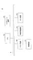
- FIG. 2 is a diagram illustrating a functional configuration example of the estimation device according to the first embodiment.
- the estimation device 10 includes a DNS response collection unit 11, a DNS response statistical processing unit 12, a flow information collection unit 13, a flow information statistical processing unit 14, a graph generation unit 15, a traffic amount estimation unit 16, and an estimated value conversion. Part 17 and the like. Each of these units is realized by processing that one or more programs installed in the estimation apparatus 10 cause the CPU 104 to execute.
- the estimation apparatus 10 also uses a DNS log storage unit 121, a flow information storage unit 122, and a graph information storage unit 123.
- the DNS log storage unit 121, the flow information storage unit 122, and the graph information storage unit 123 can be realized using, for example, the auxiliary storage device 102 in FIG. 1 or a storage device that can be connected to the estimation device 10 via a network. It is.
- the DNS response collection unit 11 collects DNS (Domain Name System) response packets observed on the network.
- DNS response packet collection method is not limited to a specific one.
- DNS response packets may be collected by packet capture from a DNS cache server or a network relay device (for example, a router or a switch).
- the DNS response statistical processing unit 12 performs statistical processing on the DNS response packets collected in a certain period.
- the result of the statistical processing is stored in the DNS log storage unit 121.
- the flow information collection unit 13 collects flow information on an arbitrary flow (for example, a flow between a client and a server) observed on the network (hereinafter referred to as “flow information”) via the network.
- the server is, for example, a Web server or a server that distributes content.
- a flow refers to a set of packets constituting a meaningful message (for example, a request or a response). Therefore, the destinations of packets constituting one flow, the IP address of the transmission source, and the port number are common.
- the flow information may be collected using, for example, a flow information collection function installed in the router. Alternatively, the flow information collection unit 13 may capture a packet and generate flow information from the capture information.
- Examples of the flow information communication protocol include NetFlow (see Non-Patent Document 2) and sFlow (see Non-Patent Document 3). “Source IP address”, “Destination IP address”, “Number of flows”, “Number of bytes” As long as this information can be acquired, the flow information collection method and protocol are not limited to specific ones.
- a flow is handled as a minimum unit of communication, but a packet may be handled as a minimum unit of communication. That is, the flow in the following description may be replaced with a packet.
- the flow information statistical processing unit 14 performs statistical processing on the flow information collected in a certain period.
- the result of the statistical processing is stored in the DNS log storage unit 121.
- the estimation apparatus 10 in the present embodiment may be connected to any network as long as it can collect both DNS response packets and flow information.
- networks include ISP (Internet Service Provider) backbone networks, corporate networks, university networks, data center networks, and the like.
- the graph generation unit 15 includes a graph conversion unit 151, a connected graph extraction unit 152, an attribute information addition unit 153, and the like.
- the graph conversion unit 151 converts information stored in the DNS log storage unit 121 into a directed graph. More specifically, the graph conversion unit 151 uses the domain name (including aliases) or IP address included in the DNS response packet as a node, and shows the correspondence between the domain name and the IP address or the domain names. Generate a directed graph with branches.
- the connected graph extraction unit 152 extracts a connected graph from the directed graph generated by the graph conversion unit 151.
- the connected graph extraction unit 152 decomposes the directed graph generated by the graph conversion unit 151 into one or more connected graph units.
- a connected graph is a set of nodes that can be reached by following branches of a directed graph and branches that connect the nodes.
- a general method of graph theory can be applied to the directed graph partitioning algorithm.
- Attribute information giving unit 153 gives attribute information to each node of each connected graph.
- Each node is a domain name or an IP address. Therefore, information stored in the DNS log storage unit 121 or the flow information storage unit 122 is given to each node as attribute information regarding the domain name or IP address of the node.
- the traffic amount estimation unit 16 estimates the traffic amount for each service based on the directed graph indicated by the information stored in the graph information storage unit 123.
- each service can be identified by a domain name. That is, the domain name is different for each service. However, it is difficult to identify a service by another name. This is because a plurality of aliases may be set for one service. Therefore, in this embodiment, the traffic volume is estimated for each domain name excluding the alias.
- the traffic amount estimation unit 16 includes a flow number distribution estimation unit 161 and a traffic amount calculation unit 162. Details of the functions of these units will be described later.
- the estimated value conversion unit 17 converts the internal representation of the traffic amount for each domain name estimated by the traffic amount estimation unit 16 into an expression format such as text that can be confirmed by a human. For example, the estimated value conversion unit 17 visualizes the amount of traffic for each domain name by the converted expression format.
- FIG. 3 is a flowchart for explaining an example of a processing procedure executed by the graph generation unit.
- the log information storage unit stores the statistical information measured by the DNS response statistical processing unit 12 regarding the DNS response packet collected in the period t11
- the flow information storage unit 122 stores the statistical information.
- Statistical information measured by the flow information statistical processing unit 14 regarding the flow information collected in the period t12 is stored.
- the period t11 and the period t12 may be the same or different. That the period t11 and the period t12 are the same means that the start timing and end timing of each period coincide.
- the difference between the period t11 and the period t12 means that at least one of the start time and the end time of each period is different.
- step S101 the graph conversion unit 151 reads information stored in the DNS log storage unit 121 (hereinafter referred to as “DNS log”).
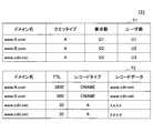
- FIG. 4 is a diagram illustrating a configuration example of the DNS log storage unit. As shown in FIG. 4, the DNS log storage unit 121 stores a DNS request table T1 and a DNS response table T2.
- the DNS request table T1 information described in the Question section of the DNS response (that is, information related to the DNS request) is stored. Specifically, in the DNS request table T1, the number of requests and the number of users are stored for each unit of the observed combination of domain name and query type.
- the domain name (strictly speaking, FQDN (Fully Qualified Domain Name) and the same applies to the following domain names) is the domain name that is the target of the inquiry in the DNS request (that is, the domain name subject to name resolution). is there.
- the query type is a record that is an inquiry target in the DNS request. “A” indicates an A record. Although not shown in FIG. 4, the query type when the AAAA record is the target of the inquiry is “AAAA”.
- the number of requests is the number of DNS responses including a question section corresponding to “domain name” and “query type”. Since one DNS response may be composed of a plurality of DNS response packets, the number of DNS responses is used here.
- the number of users is the number of types of destination IP addresses of a DNS response packet related to a DNS response including a question section corresponding to “domain name” and “query type”. That is, the number of users is the number of types of DNS request sources.
- the number of requests and the number of users for each “domain name” and “query type” are measured by the DNS response statistical processing unit 12. In FIG. 4, the values of the number of requests and the number of users are indicated by symbols for convenience, but are actually numerical values.
- the DNS response table T2 stores information on the A record, AAAA record, CNAME record, etc. described in the Answer section of the DNS response. Specifically, in the DNS response table T2, TTL (Time To Live) is stored for each unit of the combination of the observed domain name, record type, and record data.
- Domain name is the domain name that is the target of name resolution.
- the record type is the type of record included in the DNS response.
- the record data is a value of a record included in the DNS response (that is, a value associated with the domain name).
- the value of the record data is an IP address (IP address of IPv4 or IP address of IPv6).
- the record is a CNAME record (that is, when the record type is “CNAME”)
- the value of the record data is an alias.
- the TTL is an estimated value of the maximum value of the expiration date of the domain name cache.
- the maximum expiration date is a value defined in the zone file setting file of “DNS authoritative server”, and is set by a network administrator or the like. Since the TTL of each record in the observed DNS response packet is the remaining number of seconds at the time of observation of the DNS response packet, it is not necessarily the maximum value. Therefore, the DNS response statistical processing unit 12 is observed for each record in which the domain name, the record type, and the record data overlap among the A records or CNAME records included in the DNS response packet observed in the period t11. The maximum value in the TTL is measured, and the measurement result is estimated as the maximum TTL value of the record.
- the graph conversion unit 151 reads the flow information statistical information (hereinafter referred to as “flow information log”) stored in the flow information storage unit 122 (step S102).
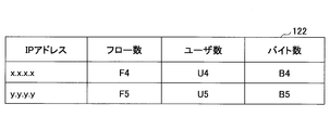
- FIG. 5 is a diagram illustrating a configuration example of the flow information storage unit.
- the flow information storage unit 122 stores the number of flows, the number of users, and bytes for each IP address of the observed flow (that is, for each unit in which the IP address is common for the observed flow). Numbers are stored.
- IP address is the IP address on the server side.
- the server-side IP address is the source IP address or the destination IP address of the observed flow.
- the estimation apparatus 10 When the estimation apparatus 10 is operated by an ISP or the like, the IP address of each client is assigned by the ISP. In other words, the estimation apparatus 10 can maintain a list of client IP addresses.
- the flow information statistical processing unit 14 may specify which of the source IP address and the destination IP address is the IP address of the server based on such a list.
- the number of flows is the number of flows related to “IP address”.
- the number of users is the number of IP addresses on the client side of the flow related to “IP address”.
- the number of bytes is the total (data amount) of the number of bytes of the flow related to the “IP address”.
- the number of flows, the number of users, and the number of bytes are measured by the flow information statistical processing unit 14.
- the values of the number of flows, the number of users, and the number of bytes are indicated by symbols for convenience, but are actually numerical values.
- the graph conversion unit 151 converts the contents of the DNS response table T2 into a directed graph (step S103).
- FIG. 6 is a diagram illustrating an example of a directed graph based on the DNS response table.
- the graph g1 in FIG. 6 corresponds to the DNS response table T2 shown in FIG. That is, each node of the graph g1 is the domain name or record data (IP address or alias) of the DNS response table T2.
- the node n1, the node n2, and the node n3 are domain name nodes.
- Nodes n4 and n5 are IP address nodes.
- the graph g1 shows a correspondence relationship between the domain name and the record data in the DNS response table T2, and includes a directional branch having a direction from the domain name to the record data.
- the connected graph extraction unit 152 decomposes the directed graph generated by the graph conversion unit 151 into units of connected graphs, and extracts each connected graph (step S104).
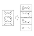
- FIG. 7 is a diagram for explaining extraction of a connected graph. If the directed graph generated in step S103 is surrounded by a broken-line rectangle on the left side of FIG. 7, four connected graphs are extracted as shown on the right side of FIG. In the present embodiment, the graph g1 is extracted as it is as one connected graph.
- the attribute information assigning unit 153 assigns attribute information to each node of each connected graph (step S105).
- FIG. 8 is a diagram for explaining the assignment of attribute information to each node of the connected graph.
- the assigned attribute information is shown in the format of “ ⁇ number of requests> / ⁇ number of users> / ⁇ TTL>”.
- the number of flows, the number of users, and the number of bytes of the record corresponding to the node are given to each node of the IP address in the flow information storage unit 122.
- the assigned attribute information is shown in the format of “ ⁇ number of flows> / ⁇ number of users> / ⁇ number of bytes>”.
- the total number of flows assigned to the nodes (node n4 and node n5) of each IP address There is a possibility that the total number of requests given to the nodes (node n1 and node n2) of the domain name excluding the intermediate node does not match. In this case, there is a possibility that the estimation accuracy of the flow transformation matrix H estimated by the flow number distribution estimation unit 161 described later deteriorates.
- the attribute information assigning unit 153 normalizes the number of requests for each node so that the total number of requests for each domain name excluding the intermediate node is 1 for each connected graph, and the IP address The number of flows of each node of the IP address may be normalized so that the total number of flows of each node is 1.
- graph information information indicating each connected graph generated by the graph generation unit 15 (hereinafter referred to as “graph information”) is stored in the graph information storage unit 123.
- the generation period of the graph information is equal to or longer than the period of the statistical processing of the DNS response packet by the DNS response statistical processing unit 12 and is longer than the period of the statistical processing of the flow information by the flow information statistical processing unit 14. It may be a period.
- the DNS log DNS request table T1 and DNS response table T2 stored last in the DNS log storage unit 121 at the time when the generation time of graph information (hereinafter referred to as “graph generation time”) arrives, and flow information Graph information may be generated using the flow information log stored last in the storage unit 122.
- the graph information generated at each graph generation time is stored in the graph information storage unit 123 in association with the graph generation time. For example, assuming that the graph generation time corresponding to the period t11 and the period t12 is the graph generation time t1, the graph information generated based on the DNS log in the period t11 and the flow information log in the period t12 is the graph generation time t1.
- the graph information is stored in the graph information storage unit 123 in association with each other.
- the DNS log stored in the DNS log storage unit 121 in the period t21, which is a fixed period after the period t11, and the flow information storage unit 122 stored in the period t22, which is a fixed period after the period t12.
- Graph information indicating each connected graph generated based on the flow information log is stored in the graph information storage unit 123 in association with the graph generation time t2 corresponding to the period t21 and the period t22.
- FIG. 9 is a flowchart for explaining an example of a processing procedure executed by the traffic amount estimation unit.
- FIG. 9 is executed for each connected graph, in the present embodiment, the graph g1 of FIG. 6 is the processing target. Further, the execution timing of the process of FIG. 9 may be asynchronous with the execution timing of the process of FIG.
- step S201 the flow number distribution estimation unit 161 substitutes 1 for the variable t.
- the variable t is a variable for identifying the graph generation time to be processed and the number of executions after step S202.
- the flow number distribution estimation unit 161 acquires graph information corresponding to the t-th graph generation time from the graph information storage unit 123 (step S202).
- the graph information indicating the graph g1 in FIG. 8 at the graph generation time t1 is acquired.
- the flow number distribution estimating unit 161 determines the domain based on the shape feature of the graph g1 and the attribute information (that is, the DNS log and the flow information log) assigned to each node of the graph g1.
- a flow transformation matrix H indicating the relationship between the number of requests for each name and the number of flows for each IP address is estimated.
- the flow transformation matrix H is a matrix for estimating how the number of flows known at the nodes n4 and n5 should be distributed to the nodes n1 and n2.
- a connected graph for example, the second connected graph from the upper right and the fourth connected graph from the upper right in FIG. 7 having a single domain name node excluding the intermediate node, the domain name excluding the intermediate node. Since the number of flows of the node can be obtained by simply adding the number of flows of the node of the IP address, the subsequent processing need not be executed.
- step S203 the flow number distribution estimation unit 161 assigns a number to each node of the graph g1. If the number of each node does not overlap in one connected graph, there is no restriction on how to assign the number.
- FIG. 10 is a diagram for explaining allocation of numbers to each node of the connected graph.
- FIG. 10 shows an example in which the numbers (1), (2), (3), (4), and (5) are allocated in the order of the nodes n1, n2, n3, n4, and n5.
- the flow number distribution estimation unit 161 converts the graph g1 into the adjacency matrix A (S204).
- the number of rows and the number of columns of the adjacency matrix A are equal, and the number of rows and the number of columns are equal to the number of numbers assigned in step S203 (that is, the number of nodes in the graph g1).
- FIG. 11 is a diagram illustrating an example of an adjacency matrix based on a connected graph.
- the row direction is the source side (the side where the directional branch comes out), and the column direction is the sink side (the side where the directional branch enters).
- the adjacency matrix A is expanded as shown in the following (a) and (b) with respect to a general adjacency matrix.
- the values of A 11 and A 22 are values assigned based on the above (b). That is, the incoming order is 0 for both the node n1 and the node n2. Therefore, the values of A 11 and A 22 are 1.
- the flow number distribution estimation unit 161 extracts, from the matrix A ′, a component corresponding to the combination of the row corresponding to the node of the domain name excluding the intermediate node in the graph g1 and the column corresponding to the node of the IP address. (S step S206).
- the matrix formed by the extracted components is the initial value H init of the flow transformation matrix H.
- FIG. 12 is a diagram illustrating an example of extracting the initial value of the flow transformation matrix.
- FIG. 12 shows an example in which the components of overlapping portions of (1) rows and (2) rows and (4) columns and (5) columns in the matrix A ′ are extracted as the initial value H init. Yes.
- the flow speed distribution estimation unit 161 the initial and the initial value H init, in the graph g1 and the number of requests granted to a node of a domain name corresponding to each line of the initial value H init (FIG. 8), graph g1
- the flow transformation matrix H is estimated (step S207). Since the flow transformation matrix H is not uniquely determined by the required number and the noise included in the number of flows, in this embodiment, the local solution of the flow transformation matrix H is estimated by solving the optimization problem. Is done. For example, the following equation (1) is an example of formulation for solving the optimization problem.
- ⁇ is a parameter that determines the importance level of the initial state (initial value H init ). That is, when it is desired to obtain a solution as close as possible to the initial value H init for the flow transformation matrix H, the value of ⁇ is increased.
- vector X is an IP add node corresponding to each column of the initial value H init In the graph g1 (node n4, the node n5) Number Flow granted to (F4, F5).
- Vector Y is the domain name of the node corresponding to each row of the initial value H init In the graph g1 (node n1, the node n2) number of requests granted to (Q1, Q2).
- the flow conversion matrix H is a matrix for converting the number of flows for each IP address into the number of flows for each domain name.
- the initial value of the flow transformation matrix H may be an arbitrary value.
- a matrix in which all component values are 0 may be set as the initial value.
- steps S203 to S206 need not be executed.
- a solution conforming to the state of the graph g1 that is, the DNS response packet or the flow information observation state
- equation (1) is an example of formulation when solving as an optimization problem, and a local solution can be obtained by deriving an update equation for the flow transformation matrix H from equation (1).
- a method for solving an optimization problem such as a hill climb method may be applied (see, for example, Non-Patent Document 6).
- the flow number distribution estimating unit 161 determines whether or not the value of the variable t has reached the number of domain name nodes excluding the intermediate node of the graph g1 (step S208).
- the flow number distribution estimation unit 161 adds 1 to the variable t (step S209), and repeats step S202 and subsequent steps. That is, step S202 and subsequent steps are executed for the next graph generation time.
- the number of corresponding nodes is two, that is, the node n1 and the node n2. Accordingly, for example, step S202 and subsequent steps are executed with respect to the generation time t2, and the flow conversion matrix H for the generation time t2 is generated.
- the flow conversion matrix H is generated based on graph information whose graph generation times are different from each other by the number of domain name nodes excluding the intermediate node of the graph g1.
- a flow conversion matrix H1 for the graph generation time t1 and a flow conversion matrix H2 for the graph generation time t2 are generated. The reason for this will be described later.
- step S210 the flow conversion matrix H or the like is used, and the traffic amount calculation unit 162 calculates an estimated value of the traffic amount for each domain name.
- step S210 the traffic amount calculation unit 162 adds the data whose value is unknown (that is, the data whose value is to be estimated) and the data whose value is known (that is, given to each node of the graph g1 as attribute information. Variable for each of the data).
- variables are defined as follows. [Known data] Ra: Number of bytes per flow of each IP address Sa: Number of flows of each IP address Ba: Number of bytes of each IP address Sd: Number of flows of each domain name Note that the number of flows Sd of each domain name is obtained from the DNS log. Although it cannot be approximated by the number of requests, the value is substituted.
- Rd Number of bytes per flow of each domain name
- Bd Number of bytes of each domain name
- the traffic amount calculation unit 162 generates the traffic amount estimation formula (2) using the flow conversion matrix H using the number of bytes per flow Rd of each domain as an unknown variable (step S211).
- the number of unknown variables included in Rd matches the number of domain names excluding intermediate nodes of each adjacency matrix. Simultaneous linear equations can be obtained by developing the estimation equation (2).
- simultaneous linear equations are generated for the number of dimensions of Rd. Specifically, simultaneous linear equations are generated using each of the flow transformation matrices H generated by the number of nodes having domain names excluding intermediate nodes. Therefore, in the present embodiment, the following two simultaneous linear equations (3) are generated for the graph generation time t1 and the graph generation time t2.
- Sd1, H1, and Ba1 are Sd and the flow transformation matrices H and Ba corresponding to the graph generation time t1.
- Sd2, H2, and Ba2 are Sd and the flow transformation matrices H and Ba corresponding to the graph generation time t2.
- steps S202 to S207 are repeated by that number.
- Rd is invariant with respect to time or changes are small.
- Such assumptions are generally considered reasonable. This is because the number of bytes per flow depends on the service, and the degree of dependence on time is considered to be small. For example, if a moving image site is compared with a simple text information site, the moving image site is considered to have a larger number of bytes per flow, and the relationship is more likely to be invariant with respect to time. Therefore, this embodiment is suitable for an environment in which the number of bytes per flow is less dependent on time.
- the traffic amount calculation unit 162 calculates Rd by solving the simultaneous linear equations (3) (step S212).
- Rd may not be uniquely determined due to the effect of observed DNS response packet or flow information noise. In that case, the method of obtaining the local solution of Non-Patent Document 6 may be used.
- the traffic amount calculation unit 162 obtains Bd by multiplying Rd obtained in step S212 by Sd (step S213). That is, the following calculation is executed.
- Bd is the target traffic volume for each domain name.
- Non-Patent Document 5 a method other than the above may be employed as a method for estimating the traffic volume for each domain name.
- element technology such as an optimization algorithm as described in Non-Patent Document 5 may be used.
- the estimated value conversion unit 17 outputs the traffic volume for each domain name estimated as described above, for example, in a format as shown in FIG.
- FIG. 13 is a diagram showing an output example of the traffic volume estimation result for each domain name.
- a graph g2 is shown in addition to the graph g1, a graph g2 is shown.
- the graph g2 is a connected graph extracted together with the graph g1.
- the traffic volume is obtained for the four domain names of the non-intermediate node.
- the estimated value conversion unit 17 visualizes these traffic amounts, for example, in the format shown in the table T3.
- the table T3 shows the estimated traffic volume for each domain name. Note that the arrangement order of the rows in the table T3 may be sorted according to the estimated traffic volume. That is, the ranking of the estimated traffic volume for each domain name may be output.
- the output form is not limited to a predetermined one. For example, it may be displayed on a display device or printed on a printer. Or you may transmit to another computer via a network.
- the statistically input data (DNS log and flow information log) is converted into a directed graph by the graph generation unit 15, and while utilizing the characteristics of the directed graph, the traffic The traffic estimation unit 16 estimates the traffic volume for each domain name based on the statistical information.
- individual users and packet units are not required to be linked. That is, in this embodiment, each DNS response packet and each flow information are not linked one by one, but by associating the DNS response packet statistical information with the flow information statistical information, Traffic volume is estimated. Therefore, it is possible to cope with a case where the DNS log and the flow information transmission user groups differ depending on the collection location and collection time of the DNS response packet and the flow information. Therefore, restrictions on information collection for estimating the traffic volume for each domain name can be relaxed.
- the traffic amount calculation unit 162 in the second embodiment generates the following estimation formula (4) in step S211 of FIG.
- the flow conversion matrix H is not used. Therefore, steps S201 to S208 in FIG. 9 may not be executed. Further, the process of FIG. 3 may not be executed. In this case, the simultaneous linear equations for each graph generation time are as follows.
- the second embodiment is preferably applied when sufficient observation data (DNS response packet and flow information) is accumulated. This is because the more observation data there is, the higher the possibility that the deterioration in the estimation accuracy of the traffic amount for each domain name can be avoided even if the flow transformation matrix H is not used.
- FIG. 14 is a diagram illustrating a functional configuration example of the estimation device according to the third embodiment. 14, the same parts as those in FIG. 2 are denoted by the same reference numerals, and the description thereof is omitted.
- the estimation apparatus 10 further includes a request number correction unit 18 and a flow information correction unit 19.
- the request number correction unit 18 estimates the number of accesses to the server or the number of flows by the client using the number of requests and TTL included in the DNS log, and replaces the number of requests in the DNS log with the estimation result. That is, the number of requests included in the DNS log is different from the number of accesses to the server or the number of flows by the client.
- URL Uniform Resource Locator
- name resolution is attempted for the domain name included in the URL.
- a DNS response caching mechanism stub resolver
- the request number correction unit 18 estimates the number of accesses to the actual server using the TTL and the request number. For example, the number of requests may be corrected by estimating the number of name resolutions performed in the period specified by TTL and adding the estimation result to the initial number of requests.
- the number of requests in the DNS request table T1 shown in FIG. 4 is a value after correction.
- the flow information correction unit 19 corrects the number of flows, the number of users, and the number of bytes in the flow information log. That is, in a general network device such as a router, flow information is collected while performing regular sampling for performance reasons. For example, flow information relating to one packet is collected every 1000 packets. The number of flows, the number of users, and the number of bytes based on the flow information sampled in this way are smaller than the actual values.
- the flow information correction unit 19 estimates the number of flows before sampling, the number of users, and the number of bytes, and corrects the content of the flow information log based on the estimation result. For example, correction may be performed based on the sampling rate. If the sampling rate is 1/1000, correction may be performed by multiplying the values of the number of flows, the number of users, and the number of bytes by 1000. Alternatively, the correction may be performed by other methods.
- the number of requests in the DNS response table T2 shown in FIG. 4 is a value after correction.
- the number of DNS log requests and the value of the flow information log can be brought close to actual values, so that the estimation accuracy of the traffic amount for each domain name is expected to be improved. can do.
- the DNS response statistical processing unit 12 is an example of a first measurement unit.
- the flow information statistical processing unit 14 is an example of a second measurement unit.
- the graph generation unit 15 is an example of a generation unit.
- the flow number distribution estimation unit 161 is an example of a matrix estimation unit.
- the traffic amount calculation unit 162 is an example of a calculation unit.
Landscapes
- Engineering & Computer Science (AREA)
- Computer Networks & Wireless Communication (AREA)
- Signal Processing (AREA)
- Data Mining & Analysis (AREA)
- Data Exchanges In Wide-Area Networks (AREA)
- Maintenance And Management Of Digital Transmission (AREA)
Abstract
推定装置は、観測されるDNS応答に基づいて、ドメイン名ごとのDNS要求の数を計測し、観測されるフローについてIPアドレスごとのフロー数及びデータ量の合計を計測し、前記ドメイン名又はIPアドレスをノードとし、ドメイン名及びIPアドレスの間の対応関係を枝とするグラフを生成し、ノードを構成する各IPアドレスのデータ量と、中間ノードを除くノードを構成するドメイン名のDNS要求の数との関係を示す変換行列を推定し、ドメイン名ごとの要求数に各ドメイン名のフローごとのデータ量を乗じた値が、変換行列にIPアドレスごとのデータ量を乗じた値に等しいとして、各ドメイン名のフローごとのデータ量を求め、当該データ量に、ドメイン名ごとのDNS要求の数を乗じて、ドメイン名ごとのデータ量を推定する。
Description
本発明は、推定装置、推定方法、及び記録媒体に関する。
近年、動画配信サービスをはじめとする、多数のユーザを抱えるインターネット上のサービスにおいて、コンテンツの配信元サーバを地理的、又はネットワーク的に分散させることで、トラヒックの分散、サーバ負荷の分散、あるいは遅延時間の低減を図る仕組みが導入されている。特に、CDN(Contents Delivery Network)は、配信元サーバを分散させることに特化したサービスであり、現在、多くのインターネット・サービスが、CDNを利用してコンテンツの配信を行っている。
一方で、CDNでは配信元サーバの各IPアドレスが複数のサービスで共用される場合がある。この運用形態により、CDN経由のトラヒックの統計情報を知りたい場合において、フロー情報に含まれるIPアドレスの情報では、そのIPアドレスに紐付く配信元サービスを一意に特定することが困難である。
上記の課題を解決する方法の一つとして、DPI(Deep Packet Inspection)が存在する。DPIはパケットのペイロード領域(OSI(Open Systems Interconnection)参照モデルではレイヤ5から7に該当する領域)をも含めたパケット分析方式全般を指す。DPIを用いて、パケットのペイロード領域に含まれるサービス名や識別子を抽出することにより、そのパケットのサービス名の特定が可能である。例えば、HTTP(HyperText Transfer Protocol)パケットの場合は、HTTPリクエスト・パケットのHTTPヘッダに含まれる「HOSTフィールド」を参照することで、そのパケットのサービス名を特定できる。
しかしながら、パケットのペイロード領域にサービスを特定する情報が含まれていない場合には、DPIを適用してサービス名を特定するのは困難である。また、パケットが暗号化されておりペイロード領域を参照できない場合においても、DPIの適用は困難である。更に、DPIでは、全てのパケットについて、ペイロード領域も含めてキャプチャを行い、なおかつ平行して分析を行うため、測定装置のコストと負荷が高く、大容量トラヒックへの適用は現実的には困難である。
一方、DPIを用いずに、かつ、暗号化通信にも適用できる方式として、DNS(Domain Name System)ログとフロー情報とを突合してフローのサービスを識別する方式が提案されている(例えば、非引用文献4参照)。非引用文献4では、DNSログとフロー情報とが同一地点で収集される。その上で、あるユーザが送受信したフローと、該フローの直近に該ユーザが送受信したDNSパケットの問い合わせドメイン名とを紐付けることで、該フローのドメイン名(すなわち、サービスの識別名)が推定される。この方式はフロー情報とDNSログとを同一地点で収集するという条件において、HTTP通信では75%から97%の推定精度、暗号化通信(TLS(Transport Layer Security))では74%から96%の推定精度を示している。
Domain Names:Implementation and Specification,https://www.ietf.org/rfc/rfc1035.txt
Cisco Systems NetFlow Services Export Version9,http://www.ietf.org/rfc/rfc3954.txt
InMon Corporation's sFlow:A Method for Monitoring Traffic in Switched and Routed Networks,https://www.ietf.org/rfc/rfc3176.txt
Bermudez,Ignacio N.,et al,"DNS to the rescue: discerning content and services in a tangled web",In:Proceedings of the 2012 ACM conference on Internet measurement conference,ACM,2012,p.413-426,2012.
P.-A.Absil,et all,(2007),Optimization Algorithms on Matrix Manifolds,pp.10-14,ISBN 978-0-691-13298-3.
Russell,Stuart J.,Norvig Peter,(2003),Artificial Intelligence:A Modern Approach (3rd ed.),Upper Saddle River,New Jersey:Prentice Hall,pp.122-125,ISBN 978-0-13-604259-4.
しかしながら、フロー情報とDNSログとが異なる場所で収集される環境においては、フローと直近のDNSパケットの突合は困難である。したがって、引用文献4に記載された方式では、斯かる環境において収集されたフロー情報とDNSログとに基づいて、サービス名単位(例えば、ドメイン名単位)のトラヒック量を推定するのは困難である。
本発明は、上記の点に鑑みてなされたものであって、ドメイン名ごとのトラヒック量の推定のための情報収集に関する制約を緩和することを目的とする。
そこで上記課題を解決するため、推定装置は、ネットワークにおいて観測されるDNS応答に基づいて、ドメイン名ごとのDNS要求の数を計測する第一の計測部と、ネットワークにおいて観測されるフローについて、IPアドレスが共通する単位ごとに、フロー数及びデータ量の合計を計測する第二の計測部と、前記DNS応答に含まれるドメイン名又はIPアドレスをノードとし、前記ドメイン名及び前記IPアドレスの間の対応関係を枝とするグラフを生成する生成部と、前記グラフのノードを構成する各IPアドレスに関して前記第二の計測部によって計測されたデータ量と、前記グラフの中間ノードを除くノードを構成するドメイン名に関して前記第一の計測部によって計測されたDNS要求の数との関係を示す変換行列を推定する行列推定部と、前記ドメイン名ごとの要求数に前記各ドメイン名のフローごとのデータ量を乗じた値が、前記変換行列に前記IPアドレスごとのデータ量を乗じた値に等しいとする関係に基づいて、前記各ドメイン名のフローごとのデータ量を求め、当該データ量に、ドメイン名ごとのDNS要求の数を乗じて、ドメイン名ごとのデータ量の推定値を算出する算出部と、を有する。
ドメイン名ごとのトラヒック量の推定のための情報収集に関する制約を緩和することができる。
以下、図面に基づいて本発明の実施の形態を説明する。図1は、第一の実施の形態における推定装置のハードウェア構成例を示す図である。図1の推定装置10は、それぞれバスBで相互に接続されているドライブ装置100、補助記憶装置102、メモリ装置103、CPU104、及びインタフェース装置105等を有する。
推定装置10での処理を実現するプログラムは、CD-ROM等の記録媒体101によって提供される。プログラムを記憶した記録媒体101がドライブ装置100にセットされると、プログラムが記録媒体101からドライブ装置100を介して補助記憶装置102にインストールされる。但し、プログラムのインストールは必ずしも記録媒体101より行う必要はなく、ネットワークを介して他のコンピュータよりダウンロードするようにしてもよい。補助記憶装置102は、インストールされたプログラムを格納すると共に、必要なファイルやデータ等を格納する。
メモリ装置103は、プログラムの起動指示があった場合に、補助記憶装置102からプログラムを読み出して格納する。CPU104は、メモリ装置103に格納されたプログラムに従って推定装置10に係る機能を実行する。インタフェース装置105は、ネットワークに接続するためのインタフェースとして用いられる。
図2は、第一の実施の形態における推定装置の機能構成例を示す図である。図2において、推定装置10は、DNS応答収集部11、DNS応答統計処理部12、フロー情報収集部13、フロー情報統計処理部14、グラフ生成部15、トラヒック量推定部16、及び推定値変換部17等を有する。これら各部は、推定装置10にインストールされる1以上のプログラムが、CPU104に実行させる処理により実現される。推定装置10は、また、DNSログ記憶部121、フロー情報記憶部122、及びグラフ情報記憶部123を利用する。DNSログ記憶部121、フロー情報記憶部122、及びグラフ情報記憶部123は、例えば、図1の補助記憶装置102、又は推定装置10にネットワークを介して接続可能な記憶装置等を用いて実現可能である。
DNS応答収集部11は、ネットワーク上において観測されるDNS(Domain Name System)応答パケットを収集する。DNS応答パケットの収集方法は、特定のものに限定されない。例えば、DNSキャッシュサーバ又はネットワーク中継装置(例えば、ルータ、スイッチ)より、パケットキャプチャによってDNS応答パケットが収集されてもよい。
DNS応答統計処理部12は、一定期間において収集されたDNS応答パケットについて統計処理を実行する。統計処理の結果は、DNSログ記憶部121に記憶される。
フロー情報収集部13は、ネットワーク上において観測される任意のフロー(例えば、クライアントとサーバとの間のフロー)に関する情報(以下、「フロー情報」という。)をネットワークを介してフロー情報を収集する。サーバとは、例えば、Webサーバやコンテンツを配信するサーバ等である。フローとは、一つの意味の有るメッセージ(例えば、要求又は応答等)を構成するパケットの集合をいう。したがって、一つのフローを構成するパケットの宛先、送信元のIPアドレス、及びポート番号は共通する。フロー情報は、例えば、ルータに搭載されたフロー情報収集機能を用いて収集されてもよい。又は、フロー情報収集部13がパケットをキャプチャして、キャプチャ情報からフロー情報を生成してもよい。フロー情報の通信プロトコルとしてNetFlow(非特許文献2参照)やsFlow(非特許文献3参照)が挙げられるが、「送信元IPアドレス」、「宛先IPアドレス」、「フロー数」、「バイト数」の情報が取得可能であれば、フロー情報の収集方法やプロトコルは特定のものに限定されない。なお、本実施の形態では、フローが通信の最小単位として扱われるが、パケットが通信の最小単位として扱われてもよい。すなわち、以下の説明におけるフローは、パケットに置き換えられてもよい。
フロー情報統計処理部14は、一定期間において収集されたフロー情報について統計処理を実行する。統計処理の結果は、DNSログ記憶部121に記憶される。
以上から明らかなように、本実施の形態における推定装置10は、DNS応答パケットとフロー情報との両方を収集可能なネットワークであれば、どのようなネットワークに接続されていてもよい。斯かるネットワークの一例として、ISP(Internet Service Provider)のバックボーン・ネットワーク、企業内ネットワーク、大学ネットワーク、データセンタ・ネットワーク等が挙げられる。
グラフ生成部15は、グラフ変換部151、連結グラフ抽出部152、及び属性情報付与部153等を含む。グラフ変換部151は、DNSログ記憶部121に記憶されている情報を、有向グラフに変換する。より詳しくは、グラフ変換部151は、DNS応答パケットに含まれているドメイン名(別名をも含む。)又はIPアドレスをノードとし、当該ドメイン名とIPアドレス、又は当該ドメイン名同士の対応関係を枝とする有向グラフを生成する。
連結グラフ抽出部152は、グラフ変換部151によって生成された有向グラフから、連結グラフを抽出する。すなわち、連結グラフ抽出部152は、グラフ変換部151によって生成された有向グラフを、1以上の連結グラフの単位に分解する。連結グラフとは、有向グラフの枝を辿ることで到達可能な各ノードと、当該各ノード間を接続する枝との集合である。有向グラフの分割アルゴリズムはグラフ理論の一般的な方式が適用可能である。
属性情報付与部153は、各連結グラフの各ノードに属性情報を付与する。各ノードは、ドメイン名又はIPアドレスである。したがって、各ノードには、当該ノードのドメイン名又はIPアドレスに関して、DNSログ記憶部121又はフロー情報記憶部122に記憶されている情報が属性情報として付与される。
なお、グラフ生成部15によって生成された有向グラフ(各連結グラフ)を示す情報は、グラフ情報記憶部123に記憶される。
トラヒック量推定部16は、グラフ情報記憶部123に記憶されている情報が示す有向グラフに基づいて、サービスごとのトラヒック量を推定する。一般的に、ドメイン名によって各サービスを識別することができる。すなわち、サービスごとにドメイン名は異なる。但し、別名によってサービスを識別するのは困難である。一つのサービスに対して複数の別名が設定される可能性が有るからである。したがって、本実施の形態では、別名を除くドメイン名ごとに、トラヒック量が推定される。図2において、トラヒック量推定部16は、フロー数分配推定部161及びトラヒック量算出部162を含む。これら各部の機能の詳細については後述される。
推定値変換部17は、トラヒック量推定部16で推定されたドメイン名ごとのトラヒック量の内部表現を、人間が確認可能なテキスト等の表現形式に変換する。例えば、推定値変換部17は、変換後の表現形式によって、ドメイン名ごとのトラヒック量を可視化する。
以下、推定装置10が実行する処理手順について説明する。図3は、グラフ生成部が実行する処理手順の一例を説明するためのフローチャートである。図3の開始時において、ログ情報記憶部には、期間t11において収集されたDNS応答パケットに関してDNS応答統計処理部12によって計測された統計情報が記憶されており、フロー情報記憶部122には、期間t12において収集されたフロー情報に関してフロー情報統計処理部14によって計測された統計情報が記憶されている。ここで、期間t11と期間t12とは、同じであってもよいし、異なっていてもよい。期間t11と期間t12とが同じであるとは、それぞれの期間の開始時期及び終了時期が一致することをいう。期間t11と期間t12とが異なるとは、それぞれの期間の開始時期及び終了時期の少なくともいずれか一方が異なることをいう。
ステップS101において、グラフ変換部151は、DNSログ記憶部121に記憶されている情報(以下、「DNSログ」という。)を読み出す。
図4は、DNSログ記憶部の構成例を示す図である。図4に示されるように、DNSログ記憶部121には、DNS要求テーブルT1と、DNS応答テーブルT2とが記憶されている。
DNS要求テーブルT1には、DNS応答のQuestionセクションに記述された情報(すなわち、DNS要求に関する情報)が記憶されている。具体的には、DNS要求テーブルT1には、観測されたドメイン名及びクエリタイプの組み合わせの単位ごとに、要求数及びユーザ数が記憶されている。
ドメイン名(厳密にはFQDN(Fully Qualified Domain Name)であり、以下のドメイン名についても同じ。)は、DNS要求において問い合わせの対象とされたドメイン名(すなわち、名前解決の対象のドメイン名)である。クエリタイプは、当該DNS要求において問い合わせの対象とされたレコードである。「A」は、Aレコードを示す。図4には示されていないが、AAAAレコードが問い合わせの対象とされた場合のクエリタイプは、「AAAA」となる。要求数は、「ドメイン名」及び「クエリタイプ」に対応するQuestionセクションを含むDNS応答の数である。なお、1つのDNS応答は、複数のDNS応答パケットによって構成される場合も有るため、ここでは、DNS応答の数としている。ユーザ数は、「ドメイン名」及び「クエリタイプ」に対応するQuestionセクションを含むDNS応答に係るDNS応答パケットの宛先IPアドレスの種類数である。すなわち、ユーザ数は、DNS要求元の種類数である。「ドメイン名」及び「クエリタイプ」ごとの要求数及びユーザ数は、DNS応答統計処理部12によって計測される。なお、図4において、要求数及びユーザ数の値は、便宜上、記号によって示されているが、実際には数値である。
一方、DNS応答テーブルT2には、DNS応答のAnswerセクションに記述されたAレコード、AAAAレコード、又はCNAMEレコード等に関する情報が記憶されている。具体的には、DNS応答テーブルT2には、観測されたドメイン名、レコードタイプ、及びレコードデータの組み合わせの単位ごとに、TTL(Time To Live)が記憶されている。
ドメイン名は、名前解決の対象とされたドメイン名である。レコードタイプは、DNS応答に含まれているレコードのタイプである。レコードデータは、DNS応答に含まれているレコードの値(すなわち、ドメイン名に対して対応付けられている値)である。当該レコードがAレコード又はAAAAレコードである場合(すなわち、レコードタイプが「A」又は「AAAA」である場合)、レコードデータの値はIPアドレス(IPv4のIPアドレス又はIPv6のIPアドレス)である。当該レコードがCNAMEレコードである場合(すなわち、レコードタイプが「CNAME」である場合)、レコードデータの値は、別名である。TTLは、ドメイン名のキャッシュの有効期限の最大値の推定値である。有効期限の最大値とは、「DNS権威サーバ」のゾーンファイルの設定ファイルにおいて定義されている値であり、ネットワーク管理者等によって設定される。観測されるDNS応答パケット内の各レコードのTTLは、当該DNS応答パケットの観測時点での残り秒数であるため、必ずしも最大値ではない。そこで、DNS応答統計処理部12は、期間t11において観測されたDNS応答パケットに含まれているAレコード又はCNAMEレコードのうち、ドメイン名、レコードタイプ、及びレコードデータが重複するレコードごとに、観測されたTTLの中で最大の値を計測し、計測結果を、当該レコードのTTLの最大値として推定する。
続いて、グラフ変換部151は、フロー情報記憶部122に記憶されているフロー情報の統計情報(以下、「フロー情報ログ」という。)を読み出す(ステップS102)。
図5は、フロー情報記憶部の構成例を示す図である。図5に示されるように、フロー情報記憶部122には、観測されたフローのIPアドレスごとに(すなわち、観測されたフローについてIPアドレスが共通する単位ごとに)、フロー数、ユーザ数、バイト数が記憶されている。
IPアドレスは、サーバ側のIPアドレスである。サーバ側のIPアドレスは、観測されたフローの送信元IPアドレス又は宛先IPアドレスである。推定装置10がISP等によって運用される場合、各クライアントのIPアドレスは、ISPによって割り当てられる。換言すれば、推定装置10は、クライアントのIPアドレスの一覧を保持することができる。フロー情報統計処理部14は、斯かる一覧に基づいて、送信元IPアドレス又及び宛先IPアドレスのいずれがサーバのIPアドレスであるのかを特定してもよい。
フロー数は、「IPアドレス」に係るフローの数である。ユーザ数は、「IPアドレス」に係るフローのクライアント側のIPアドレスの数である。バイト数は、「IPアドレス」に係るフローのバイト数の総和(データ量)である。
フロー数、ユーザ数、及びバイト数は、フロー情報統計処理部14によって計測される。なお、図5において、フロー数、ユーザ数、及びバイト数の値は、便宜上、記号によって示されているが、実際には数値である。
続いて、グラフ変換部151は、DNS応答テーブルT2の内容を、有向グラフに変換する(ステップS103)。
図6は、DNS応答テーブルに基づく有向グラフの一例を示す図である。図6のグラフg1は、図4に示したDNS応答テーブルT2に対応する。すなわち、グラフg1の各ノードは、DNS応答テーブルT2のドメイン名又はレコードデータ(IPアドレス若しくは別名)である。具体的には、ノードn1、ノードn2、及びノードn3は、ドメイン名のノードである。ノードn4及びノードn5は、IPアドレスのノードである。
また、グラフg1は、DNS応答テーブルT2におけるドメイン名とレコードデータとの対応関係を示すと共に、ドメイン名からレコードデータへの向きを有する有向枝を含む。
続いて、連結グラフ抽出部152は、グラフ変換部151によって生成された有向グラフを、連結グラフの単位に分解し、各連結グラフを抽出する(ステップS104)。
図7は、連結グラフの抽出を説明するための図である。ステップS103において生成される有向グラフが、仮に、図7の左側の破線の矩形で囲まれたものである場合、図7の右側に示されるように、4つの連結グラフが抽出される。なお、本実施の形態では、グラフg1が、そのまま1つの連結グラフとして抽出される。
続いて、属性情報付与部153は、各連結グラフの各ノードに対して属性情報を付与する(ステップS105)。
図8は、連結グラフの各ノードへの属性情報の付与を説明するための図である。図8に示されるように、ドメイン名の各ノードに対しては、DNS要求テーブルT1において当該ノードに対応するレコードの要求数及びユーザ数と、DNS応答テーブルT2において当該ノードに対応するTTLとが付与される。図8では、「<要求数>/<ユーザ数>/<TTL>」の形式で、付与された属性情報が示されている。
一方、IPアドレスの各ノードに対しては、フロー情報記憶部122において当該ノードに対応するレコードのフロー数、ユーザ数、及びバイト数が付与される。図8では、「<フロー数>/<ユーザ数>/<バイト数>」の形式で、付与された属性情報が示されている。
なお、期間t11と期間t12との時間が相互に異なる場合、又は各期間の時間幅が相互に異なる場合、各IPアドレスのノード(ノードn4及びノードn5)に付与されたフロー数の合計と、中間ノードを除くドメイン名のノード(ノードn1及びノードn2)に付与された要求数の合計とが一致しなくなる可能性が有る。この場合、後述されるフロー数分配推定部161によって推定されるフロー変換行列Hの推定精度が劣化する可能性が有る。そこで、属性情報付与部153は、連結グラフごとに、中間ノードを除く各ドメイン名のノードの要求数の合計が1となるように、当該各ノードの要求数を正規化すると共に、IPアドレスの各ノードのフロー数の合計が1となるように、IPアドレスの各ノードのフロー数を正規化するようにしてもよい。
なお、グラフ生成部15によって生成された各連結グラフを示す情報(以下、「グラフ情報」という。)は、グラフ情報記憶部123に記憶される。グラフ情報の生成周期は、DNS応答統計処理部12によるDNS応答パケットの統計処理の周期以上であり、かつ、フロー情報統計処理部14によるフロー情報の統計処理の周期以上であれば、どのような周期であってもよい。グラフ情報の生成時期(以下、「グラフ生成時期」という。)が訪れた時点において、DNSログ記憶部121に最後に記憶されたDNSログ(DNS要求テーブルT1及びDNS応答テーブルT2)と、フロー情報記憶部122に最後に記憶されたフロー情報ログとが用いられて、グラフ情報が生成されてもよい。
各グラフ生成時期に生成されたグラフ情報は、当該グラフ生成時期に対応付けられてグラフ情報記憶部123に記憶される。例えば、期間t11と期間t12とに対応するグラフ生成時期をグラフ生成時期t1とすると、期間t11におけるDNSログと期間t12におけるフロー情報ログとに基づいて生成されたグラフ情報は、グラフ生成時期t1に対応付けられてグラフ情報記憶部123に記憶される。また、期間t11よりの後の一定期間である期間t21においてDNSログ記憶部121に記憶されたDNSログと、期間t12よりの後の一定期間である期間t22においてフロー情報記憶部122に記憶されたフロー情報ログとに基づいて生成される各連結グラフを示すグラフ情報は、期間t21及び期間t22とに対応するグラフ生成時期t2に対応付けられてグラフ情報記憶部123に記憶される。
続いて、トラヒック量推定部16が実行する処理手順について説明する。図9は、トラヒック量推定部が実行する処理手順の一例を説明するためのフローチャートである。なお、図9は、各連結グラフについて実行されるが、本実施の形態では、図6のグラフg1が処理対象とされる。また、図9の処理の実行のタイミングは、図3の処理の実行タイミングと非同期であってもよい。
ステップS201において、フロー数分配推定部161は、変数tに1を代入する。変数tは、処理対象とするグラフ生成時期と、ステップS202以降の実行回数とを識別するための変数である。
続いて、フロー数分配推定部161は、グラフ情報記憶部123から、t番目のグラフ生成時期に対応するグラフ情報を取得する(ステップS202)。ここでは、グラフ生成時期t1における、図8のグラフg1を示すグラフ情報が取得される。続くステップS203~ステップS207において、フロー数分配推定部161は、グラフg1の形状的特徴と、グラフg1の各ノードに付与された属性情報(すなわち、DNSログ及びフロー情報ログ)とに基づき、ドメイン名ごとの要求数とIPアドレスごとのフロー数との関係を示すフロー変換行列Hを推定する。本実施の形態では、グラフg1において、中間ノードを除くドメイン名のノード(すなわち、別名ではないノード)であるノードn1とノードn2とのそれぞれのトラヒック量を求めるためにそれぞれのフロー数を知りたいところ、フロー変換行列Hは、ノードn4とノードn5とにおいて既知であるフロー数が、ノードn1とノードn2とに対してどのように分配されるべきであるのかを推定するための行列である。なお、中間ノードを除くドメイン名のノードが1つである連結グラフ(例えば、図7の右側の上から2番目の連結グラフ及び上から4番目の連結グラフ)の場合、中間ノードを除くドメイン名のノードのフロー数は、IPアドレスのノードのフロー数を単純に合算することで求めることが可能であるため、以降の処理は実行されなくてもよい。
ステップS203において、フロー数分配推定部161は、グラフg1の各ノードに番号を割り振る。各ノードの番号が1つの連結グラフ内で重複しなければ、番号の割り振り方には制限が無い。
図10は、連結グラフの各ノードへの番号の割り振りを説明するための図である。図10においては、ノードn1、n2、n3、n4、n5の順に、(1)、(2)、(3)、(4)、(5)の番号が割り振られた例が示されている。
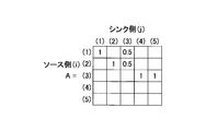
続いて、フロー数分配推定部161は、グラフg1を隣接行列Aに変換する(S204)。隣接行列Aの行数と列数は等しく、かつ、その行数及び列数は、ステップS203において割り振られた番号の個数(すなわち、グラフg1のノードの数)に等しい。
図11は、連結グラフに基づく隣接行列の一例を示す図である。図11に示される隣接行列Aにおいて、行方向がソース側(有向枝が出る側)であり、列方向がシンク側(有向枝が入る側)である。隣接行列Aへの変換方法は、基本的には、一般に知られている汎用的な方法が利用されてよい。但し、本実施の形態において、隣接行列Aは、一般的な隣接行列に対して以下の(a)及び(b)に示される拡張がなされる。
(a)ノードiからノードjに有向枝が存在し,ノードjの入次数がnの場合,Aij=1/nとする。
(b)ノードiの入次数が0の場合,ノードiの対角成分であるAii=1とする。
(a)ノードiからノードjに有向枝が存在し,ノードjの入次数がnの場合,Aij=1/nとする。
(b)ノードiの入次数が0の場合,ノードiの対角成分であるAii=1とする。
なお、図11において、0である成分の値は、便宜上、空欄とされている。
例えば、A13、A23、A34、及びA35の値は、上記(a)に基づいて割り当てられた値である。すなわち、A13、A23は、それぞれ、ノードn1からノードn3への有向枝、ノードn2からノードn3への有向枝に対応するが、ノードn3の入次数(ノードn3に入ってくる有向枝の数)は、2である。したがって、A13及びA23の値は、1/2=0.5となる。また、A34、A35は、それぞれ、ノードn3からノードn4への有向枝、ノードn3からノードn4への有向枝に対応するが、ノードn4及びノードn5のいずれについても入次数は1である。したがって、A13及びA23の値は、1/1=1となる。
一方、A11及びA22の値は、上記(b)に基づいて割り当てられた値である。すなわち、ノードn1及びノードn2のいずれについても、入次数は0である。したがって、A11及びA22の値は1とされている。
続いて、フロー数分配推定部161は、グラフg1の最大ホップ長の数だけ隣接行列Aを掛け合わせて、行列A'を求める(ステップS205)。すなわち、フロー数分配推定部161は、A'=Anを演算する(nはグラフg1の最大ホップ長)。なお、隣接行列Aをn乗ずる意義は、一般的なグラフ理論に詳しい。
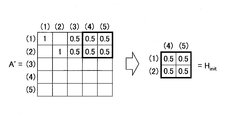
続いて、フロー数分配推定部161は、行列A'から、グラフg1における中間ノードを除くドメイン名のノードに対応する行と、IPアドレスのノードに対応する列との組み合わせに対応する成分を抽出する(SステップS206)。抽出された成分が構成する行列は、フロー変換行列Hの初期値Hinitとされる。
図12は、フロー変換行列の初期値の抽出例を示す図である。図12では、行列A'における、(1)行及び(2)行と、(4)列及び(5)列との重複部分の成分が、初期値Hinitとして抽出される例が示されている。
続いて、フロー数分配推定部161は、初期値Hinitと、グラフg1(図8)において初期値Hinitの各行に対応するドメイン名のノードに付与されている要求数と、グラフg1において初期値Hinitの各列に対応するIPアドレスに対応するノードに付与されているフロー数とに基づいて、フロー変換行列Hを推定する(ステップS207)。フロー変換行列Hは、当該要求数及び当該フロー数に含まれるノイズ等により一意に定まるものではないため、本実施の形態では、最適化問題を解くことにより、フロー変換行列Hの局所解が推定される。例えば、以下の式(1)は、最適化問題を解く場合の定式化の一例である。

また、αは、初期状態(初期値Hinit)の重視度を決めるパラメータである。すなわち、フロー変換行列Hについて、初期値Hinitにできるだけ近い解を得たい場合に、αの値は大きくされる。
更に、ベクトルXは、グラフg1において初期値Hinitの各列に対応するIPアドノード(ノードn4、ノードn5)に付与されているフロー数(F4、F5)である。ベクトルYは、グラフg1において初期値Hinitの各行に対応するドメイン名のノード(ノードn1、ノードn2)に付与されている要求数(Q1、Q2)である。
すなわち、フロー変換行列Hは、IPアドレスごとのフロー数を、ドメイン名ごとのフロー数に変換するための行列である。
なお、最適化問題を解く場合、フロー変換行列Hの初期値は、任意の値であってもよい。例えば、全ての成分の値が0である行列が初期値とされてもよい。この場合、ステップS203~S206は実行されなくてもよい。但し、本実施の形態のように、初期値Hinitを求めることで、フロー変換行列Hについて、グラフg1の状態(すなわち、DNS応答パケットやフロー情報の観測状態)に即した解が得られる可能性を高めることができる。その結果、ドメイン名ごとのトラヒック量の推定精度の向上を期待することができる。
なお、式(1)は、最適化問題として解く場合の定式化の一例であり、式(1)からフロー変換行列Hに関する更新式を導出することで局所解を求めることができる。他の例として、ヒルクライム法等の最適化問題を解く方式が適用されてもよい(例えば、非特許文献6参照)。
続いて、フロー数分配推定部161は、変数tの値が、グラフg1の中間ノードを除くドメイン名のノードの数に達したか否かを判定する(ステップS208)。変数t1の値が該当ノードの数に達していない場合(ステップS208でNo)、フロー数分配推定部161は、変数tに1を加算して(ステップS209)、ステップS202以降を繰り返す。すなわち、次のグラフ生成時期に関して、ステップS202以降が実行される。本実施の形態において、該当ノードの数は、ノードn1とノードn2との2つである。したがって、例えば、生成時期t2に関してステップS202以降が実行され、生成時期t2に対するフロー変換行列Hが生成される。
このように、フロー変換行列Hは、グラフg1の中間ノードを除くドメイン名のノードの数だけ、グラフ生成時期が相互に異なるグラフ情報に基づいて生成される。例えば、本実施の形態では、グラフ生成時期t1に対するフロー変換行列H1と、グラフ生成時期t2に対するフロー変換行列H2とが生成される。この理由については後述される。
ステップS210以降では、フロー変換行列H等が用いられて、トラヒック量算出部162によって、ドメイン名ごとのトラヒック量の推定値が算出される。
ステップS210において、トラヒック量算出部162は、値が未知であるデータ(すなわち、値が推定されるべきデータ)、及び値が既知のデータ(すなわち、グラフg1の各ノードに属性情報として付与されているデータ)のそれぞれについて変数を定義する。本実施の形態では、以下のように変数が定義される。
[既知のデータ]
Ra:各IPアドレスのフロー毎バイト数
Sa:各IPアドレスのフロー数
Ba:各IPアドレスのバイト数
Sd:各ドメイン名のフロー数
なお、各ドメイン名のフロー数Sdは、DNSログからは得られないものの、要求数で近似可能であるため、その値が代入される。
[未知のデータ]
Rd:各ドメイン名のフロー毎バイト数
Bd:各ドメイン名のバイト数
本実施の形態において、既知の各データの値は、以下の通りとなる。
Ra=(B4/F4,B5/F5)
Sa=(F4,F5)
Ba=(B4,Q5)
Sd=(Q1,Q2)
なお、グラフg1に関して、中間ノードを除くドメイン名のノードの数は2であるため、Rd及びBdの次元数は2である。
[既知のデータ]
Ra:各IPアドレスのフロー毎バイト数
Sa:各IPアドレスのフロー数
Ba:各IPアドレスのバイト数
Sd:各ドメイン名のフロー数
なお、各ドメイン名のフロー数Sdは、DNSログからは得られないものの、要求数で近似可能であるため、その値が代入される。
[未知のデータ]
Rd:各ドメイン名のフロー毎バイト数
Bd:各ドメイン名のバイト数
本実施の形態において、既知の各データの値は、以下の通りとなる。
Ra=(B4/F4,B5/F5)
Sa=(F4,F5)
Ba=(B4,Q5)
Sd=(Q1,Q2)
なお、グラフg1に関して、中間ノードを除くドメイン名のノードの数は2であるため、Rd及びBdの次元数は2である。
続いて、トラヒック量算出部162は、各ドメインのフロー毎バイト数Rdを未知変数として、フロー変換行列Hを用いてトラヒック量の推定式(2)を生成する(ステップS211)。
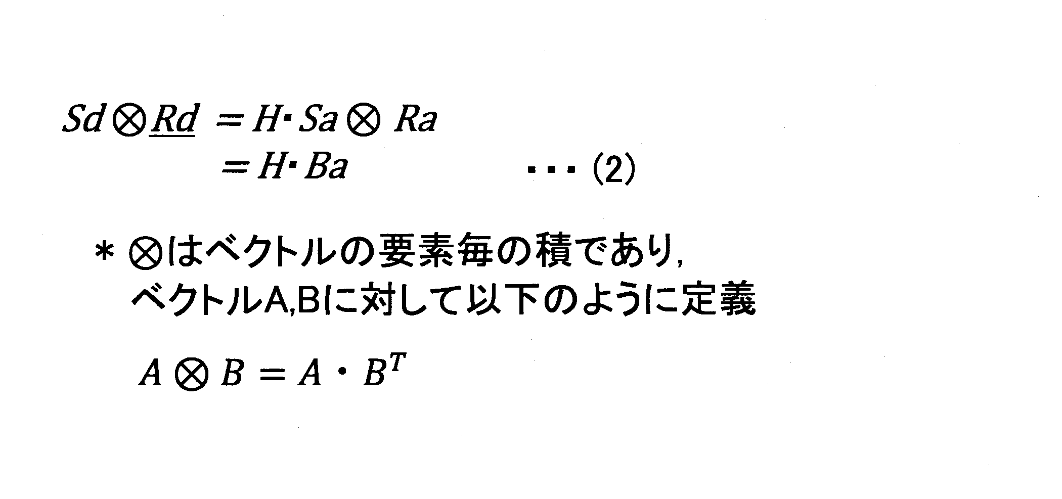
なお、連立一次方程式は、Rdの次元数分生成される。具体的には、中間ノードを除くドメイン名のノードの数だけ生成されているフロー変換行列Hのそれぞれが用いられて、連立一次方程式が生成される。したがって、本実施の形態では、グラフ生成時期t1とグラフ生成時期t2とに対する以下の2つの連立一次方程式(3)が生成される。

なお、ここでは、Rdが時刻に対して不変であること又は変化が小さいことが仮定されている。斯かる仮定は、一般的に妥当であるものと考えられる。フロー毎バイト数は、サービスに依存するものであり、時刻に対する依存度は小さいと考えられるからである。例えば、動画サイトと単なるテキスト情報のサイトとを比較すれば、動画サイトの方がフロー毎バイト数が大きいと考えられ、その関係は、時刻に対して不変である可能性が高いと考えられる。したがって、本実施の形態は、フロー毎バイト数について、時刻に対する依存度が低い環境に対して好適である。
続いて、トラヒック量算出部162は、連立一次方程式(3)を解くことで、Rdを求める(ステップS212)。但し、観測されるDNS応答パケットやフロー情報のノイズの影響等によりRdは一意に定まらない場合が有る。その場合には、非特許文献6の局所解を求める方法が利用されてもよい。
続いて、トラヒック量算出部162は、ステップS212において得られたRdに対して、Sdを乗算することにより、Bdを求める(ステップS213)。すなわち、以下の演算が実行される。

なお、ドメイン名ごとのトラヒック量の推定方法として、上記以外の方法が採用されてもよい。例えば、非特許文献5のような最適化アルゴリズム等の要素技術が用いられてもよい。
推定値変換部17は、上記のように推定された、ドメイン名ごとのトラヒック量を、例えば、図13に示されるような形式で出力する。
図13は、ドメイン名ごとのトラヒック量の推定結果の出力例を示す図である。図13では、グラフg1の他に、グラフg2が示されている。グラフg2は、グラフg1と共に抽出された連結グラフであるとする。この場合、非中間ノードの4つのドメイン名について、トラヒック量が得られる。推定値変換部17は、これらのトラヒック量を、例えば、テーブルT3に示される形式で可視化する。テーブルT3には、ドメイン名ごとに推定トラヒック量が示されている。なお、テーブルT3における行の配列順序は、推定トラヒック量によってソートされてもよい。すなわち、ドメイン名ごとの推定トラヒック量のランキングが出力されてもよい。出力形態は、所定のものに限定されない。例えば、表示装置に表示されてもよいし、プリンタに印刷されてもよい。又は、ネットワークを介して他のコンピュータに送信されてもよい。
上述したように、第一の実施の形態によれば、統計化された入力データ(DNSログ及びフロー情報ログ)が、グラフ生成部15によって有向グラフに変換され、その有向グラフの特性を活かしつつ、トラヒック量推定部16によって、統計情報に基づいてドメイン名ごとのトラヒック量が推定される。これら一連の処理の中では、個々のユーザやパケット単位の紐付けは必要とされない。すなわち、本実施の形態では、各DNS応答パケットと各フロー情報とを一つずつ紐付けるのではなく、DNS応答パケットの統計情報と、フロー情報の統計情報とを関連付けることにより、ドメイン名ごとのトラヒック量が推定される。したがって、DNS応答パケット及びフロー情報のそれぞれの収集場所や収集時刻の違いによりDNSログとフロー情報のそれぞれの送信ユーザ群が異なるケースにおいても対応可能である。よって、ドメイン名ごとのトラヒック量の推定のための情報収集に関する制約を緩和することができる。
その結果、例えば、DNS応答パケットとフロー情報とを異なる場所及び時間で収集せざるを得ない制約が有る大規模ネットワークにおいて、運用者は、サービス単位のトラヒック量を容易に把握することができ、ネットワーク監視・運用コストの削減、回線輻輳時の原因の切り分けの迅速化、あるいはネットワークの設備投資の最適化等の応用的な効果を期待することができる。
次に、第二の実施の形態について説明する。第二の実施の形態では第一の実施の形態と異なる点について説明する。第二の実施の形態において特に言及されない点については、第一の実施の形態と同様でもよい。
第二の実施の形態でのトラヒック量算出部162は、は、図9のステップS211において、以下の推定式(4)を生成する。


第二の実施の形態は、十分な観測データ(DNS応答パケット及びフロー情報)が蓄積されている場合に適用されることが好ましい。観測データが多ければ多いほど、フロー変換行列Hが利用されなくても、ドメイン名ごとのトラヒック量の推定精度の劣化が大きくなるのを回避できると可能性が高くなるからである。
次に、第三の実施の形態について説明する。第三の実施の形態では第一又は第二の実施の形態と異なる点について説明する。第三の実施の形態において特に言及されない点については、第一又は第二の実施の形態と同様でもよい。
図14は、第三の実施の形態における推定装置の機能構成例を示す図である。図14中、図2と同一部分には同一符号を付し、その説明は省略する。図14において、推定装置10は、更に、要求数補正部18及びフロー情報補正部19を有する。
要求数補正部18は、DNSログに含まれる要求数とTTLとを用いて、クライアントによるサーバへのアクセス数又はフロー数を推定し、推定結果によって、DNSログ内の要求数を置き換える。すなわち、DNSログに含まれる要求数は、クライアントによるサーバへのアクセス数又はフロー数とは異なる。通常、ユーザがWebページを閲覧するなどして、あるURL(Uniform Resource Locator)にアクセスする際には、当該URLに含まれるドメイン名に対して名前解決が試みられる。但し、一般にユーザの端末にはDNS応答をキャッシュする仕組み(スタブリゾルバ)が存在するため、クライアントによるWebページへのアクセス数に対して、観測されるDNS応答パケットは大幅に少なくなる。
そこで、要求数補正部18は、TTLと要求数とを用いて、実際のサーバへのアクセス数を推定する。例えば、TTLによって特定される期間において行われた名前解決の回数を推定し、推定結果を当初の要求数に加算することで、当該要求数が補正されてもよい。
したがって、第三の実施の形態において、図4に示されるDNS要求テーブルT1の要求数は、補正後の値となる。
一方、フロー情報補正部19は、フロー情報ログのフロー数、ユーザ数、及びバイト数を補正する。すなわち、ルータ等の一般的なネットワーク機器では、性能上の理由により定常的にサンプリングを行いながらフロー情報が収集される。例えば、1000パケットごとに1パケットに関するフロー情報が収集される。このようにサンプリングされたフロー情報に基づくフロー数、ユーザ数、及びバイト数は、実際の値よりも小さいものとなる。
そこで、フロー情報補正部19は、サンプリング前のフロー数、ユーザ数、及びバイト数を推定し、推定結果によって、フロー情報ログの内容を補正する。例えば、サンプリングの割合に基づいて補正が行われてもよい。サンプリングの割合が1/1000であれば、フロー数、ユーザ数、及びバイト数の値を1000倍することにより、補正が行われてもよい。又は他の方法によって補正が行われてもよい。
したがって、第三の実施の形態において、図4に示されるDNS応答テーブルT2の要求数は、補正後の値となる。
上述したように、第三の実施の形態によれば、DNSログの要求数やフロー情報ログの値を実際の値に近づけることができるため、ドメイン名ごとのトラヒック量の推定精度の向上を期待することができる。
なお、上記各実施の形態において、DNS応答統計処理部12は、第一の計測部の一例である。フロー情報統計処理部14は、第二の計測部の一例である。グラフ生成部15は、生成部の一例である。フロー数分配推定部161は、行列推定部の一例である。トラヒック量算出部162は、算出部の一例である。
以上、本発明の実施例について詳述したが、本発明は斯かる特定の実施形態に限定されるものではなく、特許請求の範囲に記載された本発明の要旨の範囲内において、種々の変形・変更が可能である。
本出願は、2015年2月17日に出願された日本国特許出願第2015-028744号に基づきその優先権を主張するものであり、同日本国特許出願の全内容を参照することにより本願に援用する。
10 推定装置
11 DNS応答収集部
12 DNS応答統計処理部
13 フロー情報収集部
14 フロー情報統計処理部
15 グラフ生成部
16 トラヒック量推定部
17 推定値変換部
18 要求数補正部
19 フロー情報補正部
100 ドライブ装置
101 記録媒体
102 補助記憶装置
103 メモリ装置
104 CPU
105 インタフェース装置
121 DNSログ記憶部
122 フロー情報記憶部
123 グラフ情報記憶部
151 グラフ変換部
152 連結グラフ抽出部
153 属性情報付与部
161 フロー数分配推定部
162 トラヒック量算出部
B バス
11 DNS応答収集部
12 DNS応答統計処理部
13 フロー情報収集部
14 フロー情報統計処理部
15 グラフ生成部
16 トラヒック量推定部
17 推定値変換部
18 要求数補正部
19 フロー情報補正部
100 ドライブ装置
101 記録媒体
102 補助記憶装置
103 メモリ装置
104 CPU
105 インタフェース装置
121 DNSログ記憶部
122 フロー情報記憶部
123 グラフ情報記憶部
151 グラフ変換部
152 連結グラフ抽出部
153 属性情報付与部
161 フロー数分配推定部
162 トラヒック量算出部
B バス
Claims (7)
- ネットワークにおいて観測されるDNS応答に基づいて、ドメイン名ごとのDNS要求の数を計測する第一の計測部と、
ネットワークにおいて観測されるフローについて、IPアドレスが共通する単位ごとに、フロー数及びデータ量の合計を計測する第二の計測部と、
前記DNS応答に含まれるドメイン名又はIPアドレスをノードとし、前記ドメイン名及び前記IPアドレスの間の対応関係を枝とするグラフを生成する生成部と、
前記グラフのノードを構成する各IPアドレスに関して前記第二の計測部によって計測されたデータ量と、前記グラフの中間ノードを除くノードを構成するドメイン名に関して前記第一の計測部によって計測されたDNS要求の数との関係を示す変換行列を推定する行列推定部と、
前記ドメイン名ごとの要求数に前記各ドメイン名のフローごとのデータ量を乗じた値が、前記変換行列に前記IPアドレスごとのデータ量を乗じた値に等しいとする関係に基づいて、前記各ドメイン名のフローごとのデータ量を求め、当該データ量に、ドメイン名ごとのDNS要求の数を乗じて、ドメイン名ごとのデータ量の推定値を算出する算出部と、
を有することを特徴とする推定装置。 - 前記行列推定部は、前記グラフを隣接行列に変換し、前記隣接行列を前記グラフの最大ホップ長の数だけ掛け合わせて得られる行列のうち、前記グラフの中間ノードを除くドメイン名のノードとIPアドレスのノードとの組み合わせに対応する成分を前記変換行列の初期値として抽出し、抽出された初期値と、前記グラフのノードを構成する各IPアドレスに関して前記第二の計測部によって計測されたデータ量と、前記グラフの中間ノードを除くノードを構成するドメイン名に関して前記第一の計測部によって計測されたDNS要求の数とに基づいて、前記変換行列を推定し、
前記隣接行列は、入次数が0であるノードの対角成分の値を1とし、入次数が1以上であるノードに入る枝に対応する成分の値を、当該枝の数で1を除すことにより得られる値とする、
ことを特徴とする請求項1記載の推定装置。 - 前記生成部は、前記DNS応答に含まれるドメイン名又はIPアドレスをノードとし、前記ドメイン名及び前記IPアドレスの間の対応関係を枝とする1以上の連結グラフを生成し、
前記行列推定部は、前記連結グラフごとに、前記変換行列を推定し、
前記算出部は、前記連結グラフごとに、当該連結グラフの中間ノードを除くノードを構成するドメイン名ごとの推定値を算出する、
ことを特徴とする請求項1又は2記載の推定装置。 - ネットワークにおいて観測されるDNS応答に基づいて、ドメイン名ごとのDNS要求の数を計測する第一の計測部と、
ネットワークにおいて観測されるフローについて、IPアドレスが共通する単位ごとに、フロー数及びデータ量の合計を計測する第二の計測部と、
前記ドメイン名ごとの要求数に前記各ドメイン名のフローごとのデータ量を乗じた値が、前記IPアドレスごとのデータ量に等しいとする関係に基づいて、前記各ドメイン名のフローごとのデータ量を求め、当該データ量に、ドメイン名ごとのDNS要求の数を乗じて、ドメイン名ごとのデータ量の推定値を算出する算出部と、
を有することを特徴とする推定装置。 - コンピュータが、
ネットワークにおいて観測されるDNS応答に基づいて、ドメイン名ごとのDNS要求の数を計測する第一の計測手順と、
ネットワークにおいて観測されるフローについて、IPアドレスが共通する単位ごとに、フロー数及びデータ量の合計を計測する第二の計測手順と、
前記DNS応答に含まれるドメイン名又はIPアドレスをノードとし、前記ドメイン名及び前記IPアドレスの間の対応関係を枝とするグラフを生成する生成手順と、
前記グラフのノードを構成する各IPアドレスに関して前記第二の計測手順によって計測されたデータ量と、前記グラフの中間ノードを除くノードを構成するドメイン名に関して前記第一の計測手順によって計測されたDNS要求の数との関係を示す変換行列を推定する行列推定手順と、
前記ドメイン名ごとの要求数に前記各ドメイン名のフローごとのデータ量を乗じた値が、前記変換行列に前記IPアドレスごとのデータ量を乗じた値に等しいとする関係に基づいて、前記各ドメイン名のフローごとのデータ量を求め、当該データ量に、ドメイン名ごとのDNS要求の数を乗じて、ドメイン名ごとのデータ量の推定値を算出する算出手順と、
を実行することを特徴とする推定方法。 - コンピュータが、
ネットワークにおいて観測されるDNS応答に基づいて、ドメイン名ごとのDNS要求の数を計測する第一の計測手順と、
ネットワークにおいて観測されるフローについて、IPアドレスが共通する単位ごとに、フロー数及びデータ量の合計を計測する第二の計測手順と、
前記ドメイン名ごとの要求数に前記各ドメイン名のフローごとのデータ量を乗じた値が、前記IPアドレスごとのデータ量に等しいとする関係に基づいて、前記各ドメイン名のフローごとのデータ量を求め、当該データ量に、ドメイン名ごとのDNS要求の数を乗じて、ドメイン名ごとのデータ量の推定値を算出する算出手順と、
を実行することを特徴とする推定方法。 - 請求項1乃至4いずれか一項記載の各部としてコンピュータを機能させるためのプログラムを記録したコンピュータ読み取り可能な記録媒体。
Priority Applications (1)
| Application Number | Priority Date | Filing Date | Title |
|---|---|---|---|
| US15/550,966 US10511500B2 (en) | 2015-02-17 | 2016-02-16 | Estimation device, estimation method, and recording medium |
Applications Claiming Priority (2)
| Application Number | Priority Date | Filing Date | Title |
|---|---|---|---|
| JP2015028744A JP6198195B2 (ja) | 2015-02-17 | 2015-02-17 | 推定装置、推定方法、及びプログラム |
| JP2015-028744 | 2015-02-17 |
Publications (1)
| Publication Number | Publication Date |
|---|---|
| WO2016133064A1 true WO2016133064A1 (ja) | 2016-08-25 |
Family
ID=56689007
Family Applications (1)
| Application Number | Title | Priority Date | Filing Date |
|---|---|---|---|
| PCT/JP2016/054373 Ceased WO2016133064A1 (ja) | 2015-02-17 | 2016-02-16 | 推定装置、推定方法、及び記録媒体 |
Country Status (3)
| Country | Link |
|---|---|
| US (1) | US10511500B2 (ja) |
| JP (1) | JP6198195B2 (ja) |
| WO (1) | WO2016133064A1 (ja) |
Cited By (2)
| Publication number | Priority date | Publication date | Assignee | Title |
|---|---|---|---|---|
| WO2019159822A1 (ja) * | 2018-02-13 | 2019-08-22 | 日本電信電話株式会社 | アクセス元分類装置、アクセス元分類方法及びプログラム |
| WO2023276054A1 (ja) * | 2021-06-30 | 2023-01-05 | 日本電信電話株式会社 | トラヒック監視装置及びトラヒック監視方法 |
Families Citing this family (6)
| Publication number | Priority date | Publication date | Assignee | Title |
|---|---|---|---|---|
| JP6589223B2 (ja) * | 2016-08-31 | 2019-10-16 | 日本電信電話株式会社 | サービス推定装置、サービス推定方法、及びプログラム |
| US10541967B2 (en) * | 2017-02-28 | 2020-01-21 | Roqos, Inc. | System and method for estimating and limiting usage of network applications |
| US20190319881A1 (en) * | 2018-04-13 | 2019-10-17 | Microsoft Technology Licensing, Llc | Traffic management based on past traffic arrival patterns |
| CN109889626A (zh) * | 2019-03-20 | 2019-06-14 | 湖南快乐阳光互动娱乐传媒有限公司 | 获取ip地址和dns地址的对应关系的方法及装置、系统 |
| US11770318B2 (en) * | 2021-03-15 | 2023-09-26 | T-Mobile Usa, Inc. | Systems and methods for estimating throughput |
| CN113259199B (zh) * | 2021-05-18 | 2022-08-12 | 中国互联网络信息中心 | 一种域名信用监控方法及装置 |
Citations (4)
| Publication number | Priority date | Publication date | Assignee | Title |
|---|---|---|---|---|
| JP2005348416A (ja) * | 2004-06-04 | 2005-12-15 | Lucent Technol Inc | フロー単位のトラフィック推定 |
| JP2006013876A (ja) * | 2004-06-25 | 2006-01-12 | Nippon Telegr & Teleph Corp <Ntt> | トラフィック行列生成装置並びにそのコンピュータプログラム及び通信装置並びにそのコンピュータプログラム |
| JP2006129533A (ja) * | 1998-11-24 | 2006-05-18 | Niksun Inc | 通信データを収集して分析する装置および方法 |
| JP2013157931A (ja) * | 2012-01-31 | 2013-08-15 | Nippon Telegr & Teleph Corp <Ntt> | 送信元・宛先組織特定装置及び方法及びプログラム |
Family Cites Families (5)
| Publication number | Priority date | Publication date | Assignee | Title |
|---|---|---|---|---|
| US7460487B2 (en) | 2004-06-04 | 2008-12-02 | Lucent Technologies Inc. | Accelerated per-flow traffic estimation |
| US9608886B2 (en) * | 2012-08-26 | 2017-03-28 | At&T Intellectual Property I, L.P. | Methods, systems, and products for monitoring domain name servers |
| US9904944B2 (en) * | 2013-08-16 | 2018-02-27 | Go Daddy Operating Company, Llc. | System and method for domain name query metrics |
| CN106063204A (zh) * | 2014-04-03 | 2016-10-26 | 英派尔科技开发有限公司 | 域名服务器业务量估计 |
| US10075467B2 (en) * | 2014-11-26 | 2018-09-11 | Verisign, Inc. | Systems, devices, and methods for improved network security |
-
2015
- 2015-02-17 JP JP2015028744A patent/JP6198195B2/ja active Active
-
2016
- 2016-02-16 WO PCT/JP2016/054373 patent/WO2016133064A1/ja not_active Ceased
- 2016-02-16 US US15/550,966 patent/US10511500B2/en active Active
Patent Citations (4)
| Publication number | Priority date | Publication date | Assignee | Title |
|---|---|---|---|---|
| JP2006129533A (ja) * | 1998-11-24 | 2006-05-18 | Niksun Inc | 通信データを収集して分析する装置および方法 |
| JP2005348416A (ja) * | 2004-06-04 | 2005-12-15 | Lucent Technol Inc | フロー単位のトラフィック推定 |
| JP2006013876A (ja) * | 2004-06-25 | 2006-01-12 | Nippon Telegr & Teleph Corp <Ntt> | トラフィック行列生成装置並びにそのコンピュータプログラム及び通信装置並びにそのコンピュータプログラム |
| JP2013157931A (ja) * | 2012-01-31 | 2013-08-15 | Nippon Telegr & Teleph Corp <Ntt> | 送信元・宛先組織特定装置及び方法及びプログラム |
Cited By (5)
| Publication number | Priority date | Publication date | Assignee | Title |
|---|---|---|---|---|
| WO2019159822A1 (ja) * | 2018-02-13 | 2019-08-22 | 日本電信電話株式会社 | アクセス元分類装置、アクセス元分類方法及びプログラム |
| US11290384B2 (en) * | 2018-02-13 | 2022-03-29 | Nippon Telegraph And Telephone Corporation | Access origin classification apparatus, access origin classification method and program |
| WO2023276054A1 (ja) * | 2021-06-30 | 2023-01-05 | 日本電信電話株式会社 | トラヒック監視装置及びトラヒック監視方法 |
| JPWO2023276054A1 (ja) * | 2021-06-30 | 2023-01-05 | ||
| JP7529161B2 (ja) | 2021-06-30 | 2024-08-06 | 日本電信電話株式会社 | トラヒック監視装置及びトラヒック監視方法 |
Also Published As
| Publication number | Publication date |
|---|---|
| JP2016152501A (ja) | 2016-08-22 |
| US10511500B2 (en) | 2019-12-17 |
| US20180026862A1 (en) | 2018-01-25 |
| JP6198195B2 (ja) | 2017-09-20 |
Similar Documents
| Publication | Publication Date | Title |
|---|---|---|
| JP6198195B2 (ja) | 推定装置、推定方法、及びプログラム | |
| US10284516B2 (en) | System and method of determining geographic locations using DNS services | |
| US9843554B2 (en) | Methods for dynamic DNS implementation and systems thereof | |
| EP4221132B1 (en) | System and method for identifying ott applications and services | |
| WO2019165468A4 (en) | Apparatus and methods for packetized content routing and delivery | |
| CN105491173B (zh) | 一种dns解析方法、服务器及网络系统 | |
| EP2495940A1 (en) | Collaboration between an internet service provider (ISP) and a content distribution system as well as among plural ISP | |
| JP2018528695A5 (ja) | ||
| US11283757B2 (en) | Mapping internet routing with anycast and utilizing such maps for deploying and operating anycast points of presence (PoPs) | |
| KR20190012928A (ko) | 부하분산 장치 및 방법 | |
| CN103119903A (zh) | 网络服务器之间的负载平衡 | |
| CN105959219A (zh) | 数据处理方法和装置 | |
| US10608981B2 (en) | Name identification device, name identification method, and recording medium | |
| Mori et al. | SFMap: Inferring services over encrypted web flows using dynamical domain name graphs | |
| WO2017177437A1 (zh) | 一种域名解析方法、装置及系统 | |
| CN103401799A (zh) | 负载均衡的实现方法和装置 | |
| JP5770652B2 (ja) | 送信元・宛先組織特定装置及び方法及びプログラム | |
| WO2016082627A1 (zh) | 多用户共享上网的检测方法及装置 | |
| WO2017184528A3 (en) | Content routing in an ip network that implements information centric networking | |
| Konopa et al. | Using machine learning for DNS over HTTPS detection | |
| CN101656762A (zh) | 域名服务器信息的发送方法、装置和系统 | |
| Mori et al. | Statistical estimation of the names of HTTPS servers with domain name graphs | |
| JP5921991B2 (ja) | 中継装置及びその運用方法 | |
| JP6109645B2 (ja) | サービス推定装置及び方法 | |
| JP6387332B2 (ja) | アクセス数推定装置、アクセス数推定方法、及びプログラム |
Legal Events
| Date | Code | Title | Description |
|---|---|---|---|
| 121 | Ep: the epo has been informed by wipo that ep was designated in this application |
Ref document number: 16752450 Country of ref document: EP Kind code of ref document: A1 |
|
| WWE | Wipo information: entry into national phase |
Ref document number: 15550966 Country of ref document: US |
|
| NENP | Non-entry into the national phase |
Ref country code: DE |
|
| 122 | Ep: pct application non-entry in european phase |
Ref document number: 16752450 Country of ref document: EP Kind code of ref document: A1 |