WO2016121866A1 - Digital holography recording device, digital holography playback device, digital holography recording method, and digital holography playback method - Google Patents
Digital holography recording device, digital holography playback device, digital holography recording method, and digital holography playback method Download PDFInfo
- Publication number
- WO2016121866A1 WO2016121866A1 PCT/JP2016/052487 JP2016052487W WO2016121866A1 WO 2016121866 A1 WO2016121866 A1 WO 2016121866A1 JP 2016052487 W JP2016052487 W JP 2016052487W WO 2016121866 A1 WO2016121866 A1 WO 2016121866A1
- Authority
- WO
- WIPO (PCT)
- Prior art keywords
- light
- image
- hologram
- fluorescence
- digital holography
- Prior art date
Links
- 238000001093 holography Methods 0.000 title claims description 79
- 238000000034 method Methods 0.000 title claims description 48
- 230000001678 irradiating effect Effects 0.000 claims abstract description 9
- 238000003384 imaging method Methods 0.000 claims description 126
- 238000001228 spectrum Methods 0.000 claims description 92
- 238000002073 fluorescence micrograph Methods 0.000 claims description 65
- 230000003287 optical effect Effects 0.000 claims description 56
- 238000005286 illumination Methods 0.000 claims description 54
- OAICVXFJPJFONN-UHFFFAOYSA-N Phosphorus Chemical compound [P] OAICVXFJPJFONN-UHFFFAOYSA-N 0.000 claims description 37
- 230000010363 phase shift Effects 0.000 claims description 30
- 230000001131 transforming effect Effects 0.000 claims description 7
- 238000009826 distribution Methods 0.000 description 57
- 238000001454 recorded image Methods 0.000 description 57
- 238000004088 simulation Methods 0.000 description 26
- 238000010586 diagram Methods 0.000 description 17
- 238000012545 processing Methods 0.000 description 14
- 239000000284 extract Substances 0.000 description 7
- 230000005284 excitation Effects 0.000 description 6
- 238000005259 measurement Methods 0.000 description 6
- 230000001427 coherent effect Effects 0.000 description 5
- 230000005540 biological transmission Effects 0.000 description 3
- 239000003086 colorant Substances 0.000 description 3
- 238000005094 computer simulation Methods 0.000 description 3
- 238000012986 modification Methods 0.000 description 3
- 230000004048 modification Effects 0.000 description 3
- 238000011158 quantitative evaluation Methods 0.000 description 3
- 230000008929 regeneration Effects 0.000 description 3
- 238000011069 regeneration method Methods 0.000 description 3
- 238000004458 analytical method Methods 0.000 description 2
- 238000007796 conventional method Methods 0.000 description 2
- 238000005516 engineering process Methods 0.000 description 2
- 238000011156 evaluation Methods 0.000 description 2
- 230000006870 function Effects 0.000 description 2
- 230000001172 regenerating effect Effects 0.000 description 2
- 239000004065 semiconductor Substances 0.000 description 2
- 241000251468 Actinopterygii Species 0.000 description 1
- 230000015572 biosynthetic process Effects 0.000 description 1
- WUKWITHWXAAZEY-UHFFFAOYSA-L calcium difluoride Chemical compound [F-].[F-].[Ca+2] WUKWITHWXAAZEY-UHFFFAOYSA-L 0.000 description 1
- 230000015556 catabolic process Effects 0.000 description 1
- 238000004891 communication Methods 0.000 description 1
- 230000000295 complement effect Effects 0.000 description 1
- 238000012937 correction Methods 0.000 description 1
- 238000006731 degradation reaction Methods 0.000 description 1
- 230000001066 destructive effect Effects 0.000 description 1
- 235000013399 edible fruits Nutrition 0.000 description 1
- 230000000694 effects Effects 0.000 description 1
- 238000001917 fluorescence detection Methods 0.000 description 1
- 239000010436 fluorite Substances 0.000 description 1
- 239000011521 glass Substances 0.000 description 1
- 238000003331 infrared imaging Methods 0.000 description 1
- 238000005305 interferometry Methods 0.000 description 1
- LFEUVBZXUFMACD-UHFFFAOYSA-H lead(2+);trioxido(oxo)-$l^{5}-arsane Chemical compound [Pb+2].[Pb+2].[Pb+2].[O-][As]([O-])([O-])=O.[O-][As]([O-])([O-])=O LFEUVBZXUFMACD-UHFFFAOYSA-H 0.000 description 1
- 238000000691 measurement method Methods 0.000 description 1
- 229910044991 metal oxide Inorganic materials 0.000 description 1
- 150000004706 metal oxides Chemical class 0.000 description 1
- 239000003973 paint Substances 0.000 description 1
- 230000010287 polarization Effects 0.000 description 1
- 230000001902 propagating effect Effects 0.000 description 1
- 238000000926 separation method Methods 0.000 description 1
- 239000000126 substance Substances 0.000 description 1
- 238000003786 synthesis reaction Methods 0.000 description 1
- 230000002194 synthesizing effect Effects 0.000 description 1
- 230000009466 transformation Effects 0.000 description 1
- 239000012780 transparent material Substances 0.000 description 1
Images


Classifications
-
- G—PHYSICS
- G01—MEASURING; TESTING
- G01N—INVESTIGATING OR ANALYSING MATERIALS BY DETERMINING THEIR CHEMICAL OR PHYSICAL PROPERTIES
- G01N21/00—Investigating or analysing materials by the use of optical means, i.e. using sub-millimetre waves, infrared, visible or ultraviolet light
- G01N21/62—Systems in which the material investigated is excited whereby it emits light or causes a change in wavelength of the incident light
- G01N21/63—Systems in which the material investigated is excited whereby it emits light or causes a change in wavelength of the incident light optically excited
- G01N21/64—Fluorescence; Phosphorescence
-
- G—PHYSICS
- G03—PHOTOGRAPHY; CINEMATOGRAPHY; ANALOGOUS TECHNIQUES USING WAVES OTHER THAN OPTICAL WAVES; ELECTROGRAPHY; HOLOGRAPHY
- G03H—HOLOGRAPHIC PROCESSES OR APPARATUS
- G03H1/00—Holographic processes or apparatus using light, infrared or ultraviolet waves for obtaining holograms or for obtaining an image from them; Details peculiar thereto
- G03H1/04—Processes or apparatus for producing holograms
- G03H1/08—Synthesising holograms, i.e. holograms synthesized from objects or objects from holograms
- G03H1/0866—Digital holographic imaging, i.e. synthesizing holobjects from holograms
-
- G—PHYSICS
- G01—MEASURING; TESTING
- G01H—MEASUREMENT OF MECHANICAL VIBRATIONS OR ULTRASONIC, SONIC OR INFRASONIC WAVES
- G01H1/00—Measuring characteristics of vibrations in solids by using direct conduction to the detector
- G01H1/04—Measuring characteristics of vibrations in solids by using direct conduction to the detector of vibrations which are transverse to direction of propagation
- G01H1/06—Frequency
-
- G—PHYSICS
- G03—PHOTOGRAPHY; CINEMATOGRAPHY; ANALOGOUS TECHNIQUES USING WAVES OTHER THAN OPTICAL WAVES; ELECTROGRAPHY; HOLOGRAPHY
- G03H—HOLOGRAPHIC PROCESSES OR APPARATUS
- G03H1/00—Holographic processes or apparatus using light, infrared or ultraviolet waves for obtaining holograms or for obtaining an image from them; Details peculiar thereto
- G03H1/04—Processes or apparatus for producing holograms
- G03H1/0443—Digital holography, i.e. recording holograms with digital recording means
-
- G—PHYSICS
- G03—PHOTOGRAPHY; CINEMATOGRAPHY; ANALOGOUS TECHNIQUES USING WAVES OTHER THAN OPTICAL WAVES; ELECTROGRAPHY; HOLOGRAPHY
- G03H—HOLOGRAPHIC PROCESSES OR APPARATUS
- G03H1/00—Holographic processes or apparatus using light, infrared or ultraviolet waves for obtaining holograms or for obtaining an image from them; Details peculiar thereto
- G03H1/22—Processes or apparatus for obtaining an optical image from holograms
-
- G—PHYSICS
- G03—PHOTOGRAPHY; CINEMATOGRAPHY; ANALOGOUS TECHNIQUES USING WAVES OTHER THAN OPTICAL WAVES; ELECTROGRAPHY; HOLOGRAPHY
- G03H—HOLOGRAPHIC PROCESSES OR APPARATUS
- G03H1/00—Holographic processes or apparatus using light, infrared or ultraviolet waves for obtaining holograms or for obtaining an image from them; Details peculiar thereto
- G03H1/26—Processes or apparatus specially adapted to produce multiple sub- holograms or to obtain images from them, e.g. multicolour technique
- G03H1/2645—Multiplexing processes, e.g. aperture, shift, or wavefront multiplexing
- G03H1/265—Angle multiplexing; Multichannel holograms
-
- G—PHYSICS
- G03—PHOTOGRAPHY; CINEMATOGRAPHY; ANALOGOUS TECHNIQUES USING WAVES OTHER THAN OPTICAL WAVES; ELECTROGRAPHY; HOLOGRAPHY
- G03H—HOLOGRAPHIC PROCESSES OR APPARATUS
- G03H1/00—Holographic processes or apparatus using light, infrared or ultraviolet waves for obtaining holograms or for obtaining an image from them; Details peculiar thereto
- G03H1/04—Processes or apparatus for producing holograms
- G03H1/0443—Digital holography, i.e. recording holograms with digital recording means
- G03H2001/0445—Off-axis recording arrangement
-
- G—PHYSICS
- G03—PHOTOGRAPHY; CINEMATOGRAPHY; ANALOGOUS TECHNIQUES USING WAVES OTHER THAN OPTICAL WAVES; ELECTROGRAPHY; HOLOGRAPHY
- G03H—HOLOGRAPHIC PROCESSES OR APPARATUS
- G03H1/00—Holographic processes or apparatus using light, infrared or ultraviolet waves for obtaining holograms or for obtaining an image from them; Details peculiar thereto
- G03H1/04—Processes or apparatus for producing holograms
- G03H1/0443—Digital holography, i.e. recording holograms with digital recording means
- G03H2001/0447—In-line recording arrangement
-
- G—PHYSICS
- G03—PHOTOGRAPHY; CINEMATOGRAPHY; ANALOGOUS TECHNIQUES USING WAVES OTHER THAN OPTICAL WAVES; ELECTROGRAPHY; HOLOGRAPHY
- G03H—HOLOGRAPHIC PROCESSES OR APPARATUS
- G03H1/00—Holographic processes or apparatus using light, infrared or ultraviolet waves for obtaining holograms or for obtaining an image from them; Details peculiar thereto
- G03H1/04—Processes or apparatus for producing holograms
- G03H1/0443—Digital holography, i.e. recording holograms with digital recording means
- G03H2001/0452—Digital holography, i.e. recording holograms with digital recording means arranged to record an image of the object
-
- G—PHYSICS
- G03—PHOTOGRAPHY; CINEMATOGRAPHY; ANALOGOUS TECHNIQUES USING WAVES OTHER THAN OPTICAL WAVES; ELECTROGRAPHY; HOLOGRAPHY
- G03H—HOLOGRAPHIC PROCESSES OR APPARATUS
- G03H1/00—Holographic processes or apparatus using light, infrared or ultraviolet waves for obtaining holograms or for obtaining an image from them; Details peculiar thereto
- G03H1/04—Processes or apparatus for producing holograms
- G03H1/0443—Digital holography, i.e. recording holograms with digital recording means
- G03H2001/0454—Arrangement for recovering hologram complex amplitude
- G03H2001/0456—Spatial heterodyne, i.e. filtering a Fourier transform of the off-axis record
-
- G—PHYSICS
- G03—PHOTOGRAPHY; CINEMATOGRAPHY; ANALOGOUS TECHNIQUES USING WAVES OTHER THAN OPTICAL WAVES; ELECTROGRAPHY; HOLOGRAPHY
- G03H—HOLOGRAPHIC PROCESSES OR APPARATUS
- G03H1/00—Holographic processes or apparatus using light, infrared or ultraviolet waves for obtaining holograms or for obtaining an image from them; Details peculiar thereto
- G03H1/04—Processes or apparatus for producing holograms
- G03H1/0443—Digital holography, i.e. recording holograms with digital recording means
- G03H2001/0454—Arrangement for recovering hologram complex amplitude
- G03H2001/0458—Temporal or spatial phase shifting, e.g. parallel phase shifting method
-
- G—PHYSICS
- G03—PHOTOGRAPHY; CINEMATOGRAPHY; ANALOGOUS TECHNIQUES USING WAVES OTHER THAN OPTICAL WAVES; ELECTROGRAPHY; HOLOGRAPHY
- G03H—HOLOGRAPHIC PROCESSES OR APPARATUS
- G03H1/00—Holographic processes or apparatus using light, infrared or ultraviolet waves for obtaining holograms or for obtaining an image from them; Details peculiar thereto
- G03H1/04—Processes or apparatus for producing holograms
- G03H1/08—Synthesising holograms, i.e. holograms synthesized from objects or objects from holograms
- G03H1/0866—Digital holographic imaging, i.e. synthesizing holobjects from holograms
- G03H2001/0883—Reconstruction aspect, e.g. numerical focusing
-
- G—PHYSICS
- G03—PHOTOGRAPHY; CINEMATOGRAPHY; ANALOGOUS TECHNIQUES USING WAVES OTHER THAN OPTICAL WAVES; ELECTROGRAPHY; HOLOGRAPHY
- G03H—HOLOGRAPHIC PROCESSES OR APPARATUS
- G03H1/00—Holographic processes or apparatus using light, infrared or ultraviolet waves for obtaining holograms or for obtaining an image from them; Details peculiar thereto
- G03H1/26—Processes or apparatus specially adapted to produce multiple sub- holograms or to obtain images from them, e.g. multicolour technique
- G03H1/2645—Multiplexing processes, e.g. aperture, shift, or wavefront multiplexing
- G03H2001/266—Wavelength multiplexing
-
- G—PHYSICS
- G03—PHOTOGRAPHY; CINEMATOGRAPHY; ANALOGOUS TECHNIQUES USING WAVES OTHER THAN OPTICAL WAVES; ELECTROGRAPHY; HOLOGRAPHY
- G03H—HOLOGRAPHIC PROCESSES OR APPARATUS
- G03H2222/00—Light sources or light beam properties
- G03H2222/10—Spectral composition
- G03H2222/17—White light
- G03H2222/18—RGB trichrome light
Definitions
- the present invention relates to a digital holography apparatus and a digital holography method.
- Interferometry technology using optical interference is one of the measurement methods that have been attracting attention in recent years because it can obtain three-dimensional information of an object in a non-contact and non-destructive manner.
- Digital holography is a technology for reproducing an image of a three-dimensional object using a computer from interference fringes obtained by light irradiation on the three-dimensional object.
- an interference fringe formed by object light obtained by light irradiation on a three-dimensional object and reference light that is coherent with the object light is represented by a CCD (charge-coupled device) or CMOS.
- Recording is performed using an image sensor such as (complementary metal oxide semiconductor). Based on the recorded interference fringes, a computer reproduces an image of a three-dimensional object.
- Patent Document 1 an interferometer signal obtained by digital holography, a measurement and recording step for sequentially measuring and recording a fluorescence signal from a sample, and a three-dimensional image are reconstructed from the interferometer signal and the fluorescence signal.
- a technique for performing the combining step is described.
- Patent Document 2 describes a technique for optically detecting fluorescence from an object.
- Patent Document 3 describes a technique for measuring the polarization component of fluorescence emitted from a sample.
- Patent Documents 4 to 7 describe techniques using fluorescence detection.
- the hologram by the object light including the three-dimensional shape information of the object and the fluorescence from the object are individually imaged. For example, at a first time, object light is generated from an object using a laser light source, and a hologram formed by interference between the object light and the reference light is imaged. Next, at the second time, the laser light source is turned off, fluorescence is generated from the object using the excitation light source, and only the fluorescence is imaged. As described above, in the conventional technique, the hologram and the fluorescence are individually imaged using individual light sources. Therefore, it is impossible to capture both hologram and fluorescent moving images at the camera frame rate.
- both hologram and fluorescence can be imaged simultaneously in a state where they can be separated and reproduced.
- a digital holography recording apparatus includes a light source that irradiates an object with object illumination light so that object light is generated, a hologram formed by interference between reference light and the object light, and a fluorescence image.
- the object illumination light also excites a phosphor contained in the object.
- the digital holography recording apparatus includes a light source that irradiates an object with object illumination light, a hologram formed by interference between reference light and object light from the object, and a phosphor included in the object.
- An imaging device that captures an image superimposed with an image of the emitted fluorescence.
- the digital holography reproducing device uses a spatial phase shift method to obtain the object light from an image formed by superimposing a hologram formed by interference between reference light and object light and an image of incoherent light. Is obtained, the intensity of the hologram is obtained from the complex amplitude of the object light, and the hologram is removed from the image, thereby obtaining an image of the incoherent light.
- the digital holography reproducing device performs Fourier transform on an image formed by superimposing a hologram formed by interference between reference light and object light and an image of incoherent light, and from the Fourier transformed image,
- the spatial spectrum of the object light is extracted, and the extracted spatial spectrum of the object light is subjected to inverse Fourier transform to obtain a complex amplitude of the object light, and a zero-order diffracted light component is obtained from the complex amplitude of the object light,
- a zero-order diffracted light component is removed from the Fourier-transformed image, and a spatial spectrum of the incoherent light image is extracted from the Fourier-transformed image from which the zero-order diffracted light component is removed.
- the digital holography reproducing device performs Fourier transform on an image formed by superimposing a hologram formed by interference between reference light and object light and an image of incoherent light, and from the Fourier transformed image, Extracting the spatial spectrum of the object light, inverse Fourier transform the extracted spatial spectrum of the object light, to determine the complex amplitude of the object light, to determine the intensity of the hologram from the complex amplitude of the object light,
- the incoherent light image is obtained by removing the hologram from the image.
- the object illumination is generated by irradiating the object with the object illumination light emitted from the light source, and the phosphor included in the object is excited by the object illumination light. Capturing a hologram formed by the interference between the reference light and the object light, and a fluorescence image emitted by the phosphor.
- a digital holography recording method includes a step of irradiating an object with illumination light, a hologram formed by interference between reference light and object light from the object, and a phosphor included in the object. Capturing an image on which an image of emitted fluorescence is superimposed.
- the digital holography reproducing method uses a spatial phase shift method to obtain the object light from an image formed by superimposing a hologram formed by interference between reference light and object light and an image of incoherent light.
- the digital holography reproducing method includes a step of Fourier transforming an image formed by superimposing a hologram formed by interference between reference light and object light and an image of incoherent light, and the Fourier transformed image
- the step of extracting the spatial spectrum of the object light the step of obtaining the complex amplitude of the object light by performing inverse Fourier transform on the extracted spatial spectrum of the object light, and 0 from the complex amplitude of the object light
- the digital holography reproducing method includes a step of Fourier transforming an image formed by superimposing a hologram formed by interference between reference light and object light and an image of incoherent light, and the Fourier transformed image From the step of extracting the spatial spectrum of the object light, obtaining the complex amplitude of the object light by performing an inverse Fourier transform on the extracted spatial spectrum of the object light, and from the complex amplitude of the object light Obtaining an intensity of the hologram, and removing the hologram from the image to obtain an image of the incoherent light.
- the object light and the fluorescence image can be separated and reproduced from the image in which the hologram and the fluorescence image are superimposed.
- An image of the subject recognized by a normal camera is shown.
- (A) shows a recorded image in the simulation, and (b) shows an enlarged part thereof.
- (A) shows a Fourier transform image
- (b) shows a reproduced reflected light image
- (c) shows a reproduced phase distribution.
- a state in which the zero-order diffracted light component is subtracted from the recorded image is shown.
- (A) shows the Fourier-transform image from which the 0th-order diffracted light component was removed, and (b) shows the reproduced fluorescence image.
- (A) shows the R channel image of the reflected light of the subject used in the simulation based on still another embodiment of the present invention,
- (b) shows the G channel image of the reflected light of the subject, and (c) shows the subject.
- (D) shows a reflected light image of a subject in which RGB colors are synthesized.
- (A) shows the fluorescent R channel image of the subject
- (b) shows the fluorescent G channel image of the subject
- (c) shows the fluorescent B channel image of the subject
- (d) shows RGB Indicates a fluorescent image of the subject subjected to color synthesis. The height distribution of the subject is shown. An image of the subject recognized by a normal camera is shown.
- (A), (b), and (c) are a reflected light image (reproduced image), a fluorescent image (reproduced image), and a phase distribution, respectively, obtained from the R channel recorded image.
- (A), (b), and (c) are a reflected light image (reproduced image), a fluorescent image (reproduced image), and a phase distribution, respectively, obtained from the G channel recorded image.
- (A), (b), and (c) are a reflected light image (reproduced image), a fluorescence image (reproduced image), and a phase distribution, respectively, obtained from the B channel recorded image.
- (A) is a schematic diagram explaining the relationship between the pixel of an imaging device and reference light
- (b) is a schematic diagram explaining the phase shift amount of the reference light in a part of imaging surface of an imaging device. It is a figure which shows the flow of the reproduction
- Embodiment 1 relates to a digital holography apparatus that simultaneously records object light information and fluorescence information with a single exposure.
- the digital holography apparatus can reproduce the object light information and the fluorescence information separately from each other using the recorded hologram.
- FIG. 1 is a schematic diagram showing a configuration of a digital holography device 1 of the present embodiment.
- the digital holography device 1 is an off-axis type digital holography device.
- the digital holography device 1 includes a recording device 10 (digital holography recording device) and a reproduction device 11 (digital holography reproduction device).
- the recording device 10 includes an imaging device 12, a laser light source LS1 (first light source) having a wavelength ⁇ 1, and an optical system.
- the playback device 11 can be configured by a computer such as a computer.
- As the laser light not only visible light but also invisible light (infrared rays, ultraviolet rays, X-rays, etc.) can be used.
- the optical system includes a plurality of optical elements such as mirrors, and guides laser light (coherent light) having a wavelength ⁇ 1 to the subject 13 (object) and the imaging device 12.
- the optical system includes beam splitters BS1 to BS2, mirrors M1 to M3, beam expanders BE1 to BE2, and an imaging element 15 (imaging optical element) as a plurality of optical elements.
- Each of the beam expanders BE1 to BE2 includes an objective lens BEa, a pinhole BEb, and a collimator lens BEc.
- the beam splitters BS1 and BS2 are half mirrors.
- the imaging element 15 includes a lens. However, the present invention is not limited to this, and any optical element for forming an image can be used as the imaging element 15.
- the imaging device 12 has an imaging surface in which a plurality of pixels for imaging are arranged in the x direction and the y direction, and records the intensity of light reaching the imaging surface.
- the x direction is perpendicular to the y direction.
- the z direction is perpendicular to the x and y directions.
- the imaging device 12 has an imaging element such as a CCD or a CMOS.
- the imaging device 12 records interference fringes formed on the imaging surface. This interference fringe is a hologram having information on object light.
- One pixel has a finite light receiving area. Therefore, the light intensity detected by one pixel is an integral of the light intensity of interference fringes in the light receiving region.
- the imaging device 12 does not include a color filter, one pixel of the imaging device 12 can simultaneously receive light having a plurality of wavelengths. That is, the imaging device 12 is a monochrome imaging device.
- the imaging device 12 outputs image data indicating the captured image to the playback device 11. Details of the playback device 11 will be described later.
- the laser light having the wavelength ⁇ 1 emitted from the laser light source LS1 is divided into reference light and object illumination light by the beam splitter BS1.
- the object illumination light having the wavelength ⁇ 1 divided by the beam splitter BS1 is irradiated onto the subject 13 via the mirror M1.
- the object illumination light is scattered (reflected or transmitted) or diffracted by the object 13.
- the reflected light from the subject 13 is used as the object light, but the object illumination light may be irradiated from the back of the subject 13 and the light transmitted through the subject 13 may be used as the object light.
- Object light generated by irradiating the object 13 with object illumination light passes through the imaging element 15 and the beam splitter BS2 and enters the imaging surface of the imaging device 12.
- the subject 13 includes a phosphor 14.
- the object illumination light having the wavelength ⁇ 1 also serves to excite the phosphor 14.
- the phosphor 14 excited by the object illumination light having the wavelength ⁇ 1 emits fluorescence having a predetermined wavelength corresponding to the fluorescent molecule.
- the wavelength ⁇ 1 is shorter than the wavelength of fluorescence.
- the wavelength ⁇ 1 can be equal to or greater than the wavelength of fluorescence.
- the fluorescence emitted from the phosphor 14 passes through the imaging element 15 and the beam splitter BS2 and enters the imaging surface of the imaging device 12.
- the reference light of wavelength ⁇ 1 divided by the beam splitter BS1 is reflected by the beam splitter BS2 via the mirror M2, the beam expander BE2, and the mirror M3, and enters the imaging surface of the imaging device 12.
- the angles at which the object light and the reference light are incident on the imaging surface can be adjusted by an optical element (beam splitter, mirror, etc.) included in the optical system.
- the object light from the center of the subject 13 is incident perpendicularly to the center of the imaging surface of the imaging device 12.
- the center of the subject 13 is located on a line that passes through the center of the imaging surface and is perpendicular to the imaging surface.
- the reference light is incident obliquely on the imaging surface. That is, there is an angle difference between the optical axis of the object light incident on the imaging surface and the optical axis of the reference light.
- the object light and the fluorescence are imaged by the imaging element 15 so as to form an image on the imaging surface of the imaging device 12.
- the object light interferes with the reference light to form a hologram (imaging hologram) on the imaging surface.
- fluorescence is light with low coherency called incoherent light. Further, the fluorescence has a wavelength different from that of the object light and the reference light. Therefore, the fluorescence does not interfere with the object light and the reference light.
- the imaging device 12 captures an image in which the hologram and the formed fluorescent image are superimposed. Note that an optical filter or the like that attenuates the light having the wavelength of the laser light and transmits the light having the fluorescence wavelength may be provided in front of the imaging surface.
- the intensity of the fluorescence generated from the phosphor 14 is very small compared to the intensity of the object light, the intensity of the object light or the reference light or both the object light and the reference light is optically controlled so that the fluorescence image is not buried in the hologram. It may be reduced by a filter.
- FIG. 2 is a diagram showing a flow of a reproduction process performed by the reproduction apparatus 11 of the present embodiment.
- the playback device 11 uses the image (hologram + fluorescence) recorded by the imaging device 12 to reproduce the image of the subject 13 and the fluorescence image.
- the recorded image is an image in which a hologram including object light information (that is, three-dimensional shape information of the subject 13) and fluorescence are superimposed, it cannot be reproduced as it is by a known digital holography technique. .
- the value of each pixel of the recorded image is the sum of the light intensity Ih of the hologram and the light intensity If of the fluorescence. Ih and If are different for each pixel. Since the fluorescence is imaged on the imaging surface, the light intensity If of the fluorescence represents the distribution of fluorescence viewed from the imaging device 12.
- 2 is the intensity of the object light,
- 2 is the intensity of the reference light, and ⁇ is the position of the object light with respect to the reference light.
- , and ⁇ may vary from pixel to pixel.
- the reference light is a plane wave obtained by stretching the laser light, the intensity of the reference light may be assumed (estimated) to be a uniform value or a predetermined distribution (for example, Gaussian distribution).
- the intensity distribution of only the reference light may be measured in advance or after the fact. Measuring the intensity distribution of the reference light corresponds to calibration for increasing the reproduction accuracy. Therefore,
- 2 can be treated as a known value.
- the playback device 11 performs a two-dimensional Fourier transform on the recorded image (S1).
- the hologram includes interference fringes of various intervals formed by interference between the reference light and the object light.
- the spectrums of the object light wave first-order diffracted light
- the 0th-order diffracted light and the conjugate image ( ⁇ 1st-order diffracted light) appear according to the stripe interval.
- the plane after the two-dimensional Fourier transform is called a spatial frequency plane
- the spectrum is called a spatial spectrum.
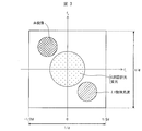
- FIG. 3 is a diagram schematically showing a two-dimensional Fourier transform of a recorded image.
- the horizontal axis represents the x-axis spatial frequency fx
- the vertical axis represents the y-axis spatial frequency fy.
- the spatial spectrum of the 0th-order diffracted light of wavelength ⁇ 1 the spatial spectrum of the object light wave (first-order diffracted light) of wavelength ⁇ 1
- the conjugate image ⁇ 1st-order diffracted light
- the spatial spectrum of the conjugate image appears at a position symmetrical to the origin with respect to the spatial spectrum of the object light wave.
- each spatial spectrum is circular.
- Such a spatial spectrum can be obtained when a light transmission filter (aperture or aperture) having a similar shape is disposed in the path of the object light.
- the spatial frequency band that can be recorded in the imaging apparatus is a range of width 1 / d centered on the origin on the spatial frequency plane. d is a pixel interval.
- the spatial spectrum of 0th order diffracted light is distributed around the origin. Many of the spatial spectra of fluorescence are also distributed around the origin. Therefore, the spatial spectrum of the zero-order diffracted light and the spatial spectrum of the fluorescence are distributed at least partially overlapping each other in the spatial frequency plane.
- the recording apparatus 10 by arranging an aperture or a stop between the subject 13 and the imaging device 12 (for example, in the vicinity of the imaging element 15), the high frequency component of the fluorescence spatial spectrum can be cut. Thereby, the spatial spectrum of fluorescence can be located mainly in the low frequency region (near the origin).
- the spatial spectrum of the object light wave of ⁇ 1 appears on the higher frequency side than the spatial spectrum of the 0th-order diffracted light.
- the interval between the interference fringes is shortened, so that the spatial spectrum of the object light wave is shifted to the high frequency side.
- the playback device 11 extracts the spatial spectrum of the object light wave from the Fourier transformed image (S2). For example, the playback device 11 extracts a predetermined range as a spatial spectrum of the object light wave from the Fourier-transformed image.
- the range in which the spatial spectrum of the object light wave is distributed depends on the wavelength of the object light, the incident angles of the object light and the reference light, and the viewing angle of the subject 13 viewed from the imaging device 12 (can be limited by an aperture or a diaphragm). To do. Therefore, the range in which the spatial spectrum of the object light wave is distributed can be known in advance.
- the reproducing device 11 performs inverse Fourier transform on the extracted spatial spectrum of the object light wave. Further, the phase modulation amount corresponding to the tilt angle of the reference light is corrected. Accordingly, the reproducing device 11 obtains the complex amplitude (the phase in which the modulation amount by the reference light is corrected from
- the result of the inverse Fourier transform represents the recorded image (hologram + fluorescence) excluding the 0th-order diffracted light, the conjugate image, and the fluorescence.
- the phase of the reference light is different for each pixel (if the reference light is a plane wave, the phase of the reference light changes periodically).
- correcting the phase modulation amount means that the phase modulation amount (according to the phase of the reference light) included in ⁇ of the object light obtained from the result of the inverse Fourier transform is determined according to the phase distribution of the reference light. Means correction (cancellation).
- the reproducing device 11 obtains
- 2 is known as described above.
- the reproducing device 11 obtains the 0th-order diffracted light component (
- the reproducing apparatus 11 subtracts the 0th-order diffracted light component (
- the reproducing device 11 performs Fourier transform on the image from which the 0th-order diffracted light component is removed (S5).
- the reproducing device 11 can extract a spatial spectrum of fluorescence by extracting a predetermined range centering on the origin from the Fourier-transformed image from which the 0th-order diffracted light component is removed.
- the reproducing device 11 obtains the fluorescence intensity distribution (fluorescence image) by performing inverse Fourier transform on the extracted fluorescence spatial spectrum (S6).
- the 0th-order diffracted light component may be subtracted from the recorded image, or the Fourier-transformed 0th-order diffracted light component may be subtracted from the Fourier-transformed image.
- the removal of the zero-order diffracted light component can be performed in either real space or Fourier space.
- the reproducing device 11 can separate and reproduce the fluorescent image from the image in which the hologram and the fluorescent image are superimposed. Further, the playback device 11 can play back the image of the subject 13 from the complex amplitude of the object light, and obtain three-dimensional shape information of the subject 13.
- a known technique can be used as a method for reproducing an image from the extracted spatial spectrum of the object light wave.
- the recording apparatus 10 generates object light and excites the phosphor 14 with object illumination light emitted from a single laser light source LS1. Since it is not necessary to separately provide a light source only for exciting the phosphor 14, the recording apparatus 10 can be downsized.
- the recording apparatus 10 simultaneously captures the hologram and the fluorescence image so that the object light and the fluorescence can be separated and reproduced by tilting the optical axis of the reference light with respect to the optical axis of the object light. That is, the recording apparatus 10 captures an image so that the spatial spectrum of the object light wave and the spatial spectrum of the 0th-order diffracted light and fluorescence are separated on the spatial frequency plane. From the hologram thus recorded, the reproducing device 11 separates and reproduces the object light and the fluorescence as described above. Since the digital holography device 1 captures the hologram and the fluorescence as one image at the same time, it is possible to record a moving image at the frame rate of the imaging device 12.
- the optical system of the recording apparatus 10 may be a transmissive optical system instead of the reflective optical system, and records light including transmitted light, diffracted light, or scattered light instead of reflected light. You can also.
- the digital holography apparatus 1 analyzes, for example, analysis of the movement of a target in a cell, high-speed characteristic evaluation of a transparent material such as fluorite or paint, and high-speed characteristic evaluation of a rough surface body or a scatterer such as fish, plant, or fruit. Etc. can be used.
- a color imaging device can also be used as the imaging device 12.
- the color imaging apparatus records RGB (red, green, and blue) color images.
- RGB red, green, and blue
- the reproduction device 11 performs the above-described separation and reproduction of the object light and the fluorescence in each color image of RGB. For example, three reproduction images corresponding to RGB are obtained for fluorescence.
- a digital holography device using a color imaging device can be used for, for example, simultaneous analysis of reflected light and fluorescence wavelength spectra of a substance.
- the fluorescence is invisible light having a wavelength longer than that of the object illumination light.
- an infrared imaging device can be used.
- a different wavelength selection filter (a filter that selectively transmits the wavelength of the invisible light region) is provided for each pixel of the imaging device, such as a color imaging device, so that object light, reference light, and fluorescence that are invisible light are provided. You may image.
- the recording apparatus 10 records (captures) an image in which a hologram formed by coherent light and a subject image formed by incoherent light emitted from the subject are superimposed.
- the reproducing device 11 reproduces the image of the subject formed by the incoherent light from the image.
- the incoherent light emitted from the subject is fluorescent has been described as an example, but of course, the incoherent light emitted from the subject is not limited to fluorescence, and any incoherent light (phosphorescence or discharge) is used. Light emission, etc.). The same applies to other embodiments.
- the reproducing device 11 may obtain the light intensity Ih of the hologram from the obtained complex amplitude of the object light.
- the reproducing device 11 can extract only the fluorescence image by subtracting the light intensity Ih of the hologram from the recorded image.
- the reproducing apparatus 11 can omit the second Fourier transform (S5) / inverse Fourier transform (S6).
- S5 second Fourier transform
- S6 inverse Fourier transform
- a mirror or a reference object is placed in the object optical path, or a plane wave or a spherical wave propagating in a direction along the optical axis is set as the object light, and the hologram is set in advance.
- the recorded hologram is Fourier transformed to extract the spatial spectrum of the object light to obtain phase information. If the light has an uncomplicated phase distribution such as a plane wave, it is easy to extract information on the amount of phase modulation by the reference light, and the angle difference can be measured (calculated) with higher accuracy. If the measurement or estimation is not accurate, the accuracy of the calculated light intensity of the hologram will be low.
- the accuracy of the obtained fluorescence image is lowered.
- the intensity of the 0th-order diffracted light can be obtained regardless of the phase of the reference light. Therefore, by performing processing as in the flow of FIG. 2, the accuracy of the obtained fluorescence image can be increased.
- the reproduction method of the present embodiment can increase the accuracy of the fluorescence image as compared with the reproduction method of Embodiment 4 described later.
- the recording apparatus 10 may perform imaging in a state where object light, reference light, and fluorescence are not generated (shielded), and output the image to the reproducing apparatus 11 as an image for calibration.
- This image is an image of stray light that becomes noise.
- the reproduction apparatus 11 may use a subtracted pixel value of the stray light image from the pixel value (intensity) of the recorded image as a calibrated recorded image. According to this, the influence of noise such as stray light can be eliminated, and the reproduction accuracy can be further increased.
- FIG. 4 is a schematic diagram showing the configuration of the digital holography device 2 of the present embodiment.
- the digital holography device 2 is an off-axis type digital holography device.
- the digital holography device 2 includes a recording device 20 (digital holography recording device) and a reproducing device 11.
- the recording device 20 includes an imaging device 12, a laser light source LS1 having a wavelength ⁇ 1, a laser light source LS2 (first light source) having a wavelength ⁇ 2, a laser light source LS3 (second light source) having a wavelength ⁇ 3, and an optical system.
- the optical system includes a plurality of optical elements such as mirrors, and guides laser light (coherent light) having wavelengths ⁇ 1 to ⁇ 3 to the subject 13 and the imaging device 12.
- the optical system includes beam splitters BS1 to BS2, mirrors M1 to M9, beam expanders BE1 to BE4, and imaging element 15 as a plurality of optical elements.
- the mirrors M5 to M9 may be composed of dichroic mirrors or polarizing beam splitters.
- the laser beams of wavelengths ⁇ 1 to ⁇ 3 are coaxially aligned by mirrors M4 and M5 and beam splitter BS1.
- Laser light having wavelengths ⁇ 1 to ⁇ 3 is split into object illumination light and reference light by beam splitter BS1.
- the object illumination light with wavelengths ⁇ 1 to ⁇ 3 is applied to the subject 13.
- the object light having the wavelengths ⁇ 1 to ⁇ 3 from the subject 13 passes through the imaging element 15 and the beam splitter BS2 and enters the imaging surface of the imaging device 12.
- the object illumination light having wavelengths ⁇ 2 and ⁇ 3 also serves to excite the phosphor 14 (the role of excitation light).
- the phosphor 14 may be excited by object illumination light having a wavelength ⁇ 1. Since the phosphor 14 is excited by a plurality of object illumination lights, the intensity of the emitted fluorescence is enhanced. Like the object light, the fluorescence emitted from the phosphor 14 passes through the imaging element 15 and the beam splitter BS2 and enters the imaging surface of the imaging device 12.
- the reference light having the wavelength ⁇ 1 passes through the mirrors M6 and M7, passes through the mirror M2, the beam expander BE2, and the mirror M3, passes through the mirrors M9 and M8, is reflected by the beam splitter BS2, and is reflected on the imaging surface of the imaging device 12. Is incident on.
- the reference light of wavelength ⁇ 2 passes through the mirror M6, is reflected by the mirror M7, passes through the beam expander BE3, is reflected by the mirror M9, passes through the mirror M8, is reflected by the beam splitter BS2, and is reflected by the imaging device 12. Incident on the imaging surface.
- the reference light of wavelength ⁇ 3 is reflected by the mirror M6, passes through the beam expander BE4, is reflected by the mirror M8, is reflected by the beam splitter BS2, and enters the imaging surface of the imaging device 12.
- the recording device 20 divides the path of the reference light for each wavelength so that the reference light is incident on the imaging surface at different incident angles (incident angle on the xz plane and incident angle on the yz plane) for each wavelength.
- the imaging device 12 is a monochrome imaging device.
- the imaging device 12 captures an image in which a plurality of holograms corresponding to a plurality of wavelengths and the formed fluorescence image are superimposed.
- FIG. 5 is a diagram schematically showing a two-dimensional Fourier transform of a recorded image.
- the horizontal axis represents the x-axis spatial frequency fx
- the vertical axis represents the y-axis spatial frequency fy.
- the playback device 11 obtains a Fourier-transformed image (FIG. 5) by performing a two-dimensional Fourier transform on the recorded image.
- the spatial spectrum of the 0th order diffracted light of each wavelength ⁇ 1 to ⁇ 3 the spatial spectrum of the object light wave (first order diffracted light) of each wavelength ⁇ 1 to ⁇ 3, and each wavelength ⁇ 1 to ⁇ 3
- the spatial spectrum of the 0th-order diffracted light of each wavelength ⁇ 1 to ⁇ 3 is distributed around the origin and overlaps each other. Many of the spatial spectra of fluorescence are also distributed around the origin. Therefore, the spatial spectrum of the zero-order diffracted light and the spatial spectrum of the fluorescence are distributed at least partially overlapping each other in the spatial frequency plane.
- the spatial spectrum of the object light wave of ⁇ 1 to ⁇ 3 appears at different positions depending on the incident angle of the reference light of each wavelength (the angle between the optical axis of the object light and the optical axis of the reference light). For example, if the reference light incident on the imaging surface is tilted in the x-axis direction, a spatial spectrum of the object light wave appears on the high frequency side of fx. Similarly, if the reference light incident on the imaging surface is inclined in the y-axis direction, a spatial spectrum of the object light wave appears on the high frequency side of fy.
- the recording apparatus 20 is configured so that the incident angles of the respective wavelengths are different so that the spatial spectra of the object light waves of the respective wavelengths can be separated (so as not to overlap).
- the playback device 11 extracts the spatial spectrum of the object light wave for each wavelength from the Fourier-transformed image. Therefore, the reproducing apparatus 11 can obtain the complex amplitude of the object light of each pixel from the extracted spatial spectrum of the object light wave for each wavelength.
- the reproducing device 11 can extract the spatial spectrum of the fluorescence by obtaining the 0th-order diffracted light component of each wavelength and removing the 0th-order diffracted light component of each wavelength from the Fourier transformed image. In this way, even when a hologram having a plurality of wavelengths and a fluorescence image are superimposed, the reproducing device 11 can separate and reproduce the object light and the fluorescence having each wavelength.
- the digital holography device 2 can perform three-dimensional color imaging of the subject 13 and obtain a fluorescent image (monochrome). Further, even when the incident angles of the reference light of each wavelength are the same, the spatial spectrum of the object light wave of each wavelength may be separated using the fact that the spatial frequency differs according to the wavelength difference. Further, when the spatial spectrum of the object light and fluorescence or the object light of each wavelength is partially overlapped, the image may be reproduced by extracting the spatial spectrum excluding the overlapping portion.
- FIG. 6 is a schematic diagram showing a configuration of the digital holography device 3 of the present embodiment.
- the digital holography device 3 is an off-axis type digital holography device.
- the digital holography device 3 includes a recording device 30 (digital holography recording device) and a reproducing device 11.
- the recording device 30 includes an imaging device 32, a laser light source LS1 having a wavelength ⁇ 1, a laser light source LS2 having a wavelength ⁇ 2, a laser light source LS3 having a wavelength ⁇ 3, and an optical system.
- the optical system includes a plurality of optical elements such as mirrors, and guides laser light (coherent light) having wavelengths ⁇ 1 to ⁇ 3 to the subject 13 and the imaging device 32.
- the optical system includes beam splitters BS1 to BS2, mirrors M1 to M5, beam expanders BE1 to BE2, and an imaging element 15 as a plurality of optical elements.
- Object illumination light, object light, and fluorescence paths are the same as in the second embodiment.
- reference lights having wavelengths ⁇ 1 to ⁇ 3 pass through the same path and are incident on the imaging surface coaxially with each other. However, there is an angle difference between the optical axis of the object light and the optical axis of the reference light.
- the imaging device 32 is a color imaging device.
- the imaging device 32 performs imaging for each of R (red), G (green), and B (blue) sub-pixels to generate a color image.
- the color image includes R channel information, G channel information, and B channel information, and an image of each color can be separated from the color image.
- light of wavelength ⁇ 1 is recorded only on the R channel
- light of wavelength ⁇ 2 is recorded only on the G channel
- light of wavelength ⁇ 3 is recorded only on the B channel. Fluorescence is recorded in one or more channels depending on its wavelength.
- the R channel image is an image in which a hologram having a wavelength of wavelength ⁇ 1 and a fluorescence image are superimposed.
- the G-channel image is an image in which a hologram having a wavelength of wavelength ⁇ 2 and a fluorescence image are superimposed.
- the B channel image is an image including only a hologram having a wavelength of wavelength ⁇ 3.
- the reproduction device 11 can separate and reproduce the object light having the wavelength ⁇ 1 and the fluorescence from the R channel image, as in the above embodiment. The same applies to the G channel image.
- the reproduction apparatus 11 can reproduce the object light having the wavelength ⁇ 3 from the B channel image, and as a result, obtain a dark image as the fluorescence image.
- the reproduction device 11 can obtain a color reproduction image by synthesizing RGB reproduction images with respect to object light or fluorescence.
- the digital holography device 3 can perform color imaging of a three-dimensional shape of the subject 13 and obtain a fluorescent color image.
- the B channel image is an image in which a hologram having a wavelength of wavelength ⁇ 3 and a fluorescence image are superimposed, a fluorescent color image can be obtained in the same manner.
- the reproducing device 11 obtains the complex amplitude of the object light using the spatial phase shift method when the phase of the reference light is spatially different (the phase of the reference light is different for each pixel on the imaging surface).
- the recording apparatus can have the same configuration as that of the first embodiment. This will be specifically described below.
- FIG. 20A is a schematic diagram for explaining the relationship between the pixels of the imaging device and the reference light
- FIG. 20B is a diagram of reference light on a part of the imaging surface (or recorded image) of the imaging device. It is a schematic diagram explaining the amount of phase shifts.
- One rectangle in FIG. 20B corresponds to one pixel.
- a plurality of pixels 12a are arranged on the imaging surface of the imaging device.
- the phase of the reference light is different for each pixel 12a in the x-axis direction.
- the phase of the reference light is 0 along the x-axis direction when the phase of the reference light in a certain pixel 12a is defined as a reference (0).
- Pixels that are ⁇ / 2, ⁇ , and 3 ⁇ / 2 are arranged.
- d is the pixel pitch. This phase shift from the reference is called a phase shift amount.
- the phase shift amount of the reference light in the hologram of the recorded image is as shown in FIG.
- the phase of the reference light is shifted obliquely.
- the difference in the amount of phase shift is not limited to ⁇ / 2.
- a spatial light modulation element array an array of elements that shift the phase, such as glass or a wave plate, a diffraction element that causes a Talbot effect, or
- a recorded image of the phase distribution of the reference light as shown in FIG. 20C may be obtained using a polarizer array or the like.
- the object light may be shifted in phase by tilting the optical axis of the object light or providing a phase shift element array in the object light path.
- FIG. 21 is a diagram showing a flow of a reproduction process performed by the reproduction apparatus 11 of the present embodiment.
- FIG. 22 is a diagram showing an outline of the flow of the reproduction process.
- a rectangle in FIG. 22 represents a pixel of an image that is partially enlarged, and a numerical value in the rectangle indicates a phase shift amount.
- the difference in phase shift amount is 2 ⁇ / 3 between adjacent pixels in the x-axis direction (horizontal direction) will be described as an example.
- a hologram in which the object light and the reference light whose phase is shifted interferes with the fluorescent image and is recorded.
- the playback device 11 extracts pixels having the same phase shift amount from the recorded image, and obtains a plurality of images for each phase shift amount.
- the playback device 11 interpolates pixel values between pixels for a plurality of images, and obtains a plurality of interpolated images (S11).
- the reproducing device 11 obtains a complex amplitude distribution of object light from a plurality of interpolated images having different phase shift amounts using a spatial phase shift method (S12). At this time, a known formula of a spatial phase shift method for obtaining the complex amplitude of the object light only from the hologram can be used.
- the playback device 11 can obtain a playback image of the subject from the complex amplitude distribution of the object light.
- the reproducing apparatus 11 obtains the distribution of the light intensity Ih of the hologram from the complex amplitude distribution of the object light, the known intensity distribution of the reference light, and the phase shift amount of the reference light (S13).
- the reproducing device 11 obtains a fluorescence image by subtracting the light intensity distribution of the hologram from the recorded image (removing the hologram) (S14). In this way, the reproducing device 11 can reproduce the object light and the fluorescent image from the recorded image in which the hologram and the fluorescent image are superimposed.
- the Fourier transform process is computationally intensive. According to the present embodiment, since Fourier transformation is not required in the reproduction process, the object light and the fluorescence image can be separated and reproduced at high speed. Therefore, the playback device 11 of the present embodiment enables playback of moving images in real time of object light and fluorescence images.
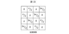
- FIG. 23 is a diagram showing the phase shift amount of the reference light in a part of the enlarged recorded image.
- the optical axis of the reference light is tilted in both the x-axis and y-axis directions, the distribution of the phase shift amount of the reference light is as shown in FIG.
- the pixel value I (x, y) of the recorded image is the sum of the light intensity If (x, y) of the fluorescence image and the light intensity Ih (x, y) of the hologram.
- x and y indicate pixel coordinates.
- Ao and Ar represent amplitudes, and ⁇ o and ⁇ r represent phases.
- j is an imaginary unit.
- M is the number of pixels in the x-axis direction
- N is the number of pixels in the y-axis direction
- the reproducing device 11 can obtain the complex amplitude of the object light.
- the reproducing device 11 obtains the distribution of the light intensity Ih of the hologram from the complex amplitude distribution of the object light, the known reference light intensity distribution, and the phase shift amount of the reference light (reference light phase). From Expression (2), the reproducing device 11 obtains the light intensity If of the fluorescence image by subtracting the light intensity Ih of the hologram from the pixel value I of the recorded image. If the intensity distribution of the reference light is uneven, the spatial phase shift method may be calculated after subtracting the intensity distribution of the reference light from the recorded image. This can alleviate the problem of image quality degradation of the output image due to unevenness of the reference light intensity.
- Simulation 1 A simulation result of hologram recording and reproduction based on Embodiment 1 of the present invention will be described. Here, it is assumed that the digital holography apparatus 1 shown in FIG. 1 is used.
- FIG. 7 shows a subject used for the simulation.
- 7A shows the reflected light image of the subject (object light image of wavelength ⁇ 1)
- FIG. 7B shows the fluorescent image of the subject
- FIG. 7C shows the subject.
- the height distribution of is shown.
- the object light having the wavelength ⁇ 1 is hardly reflected, but the fluorescence is emitted strongly.
- the image shown in FIG. 8 is recognized, and the reflected light (object light) and fluorescence cannot be separated and identified.
- the height of the subject (the height toward the imaging device in the z direction) is expressed in light and dark. The bright spot is higher than the dark spot.
- the simulation conditions are as follows.
- the number of pixels of the image sensor is 2048 ⁇ 2048 (horizontal ⁇ vertical), and the pixel pitch is 2.2 ⁇ m in the horizontal direction and 2.2 ⁇ m in the vertical direction.
- the incident angle of the reference beam is 6.05 ⁇ 10 ⁇ 2 from the z axis to the x axis (in the xz plane) and from the y axis (in the yz plane).
- the intensity ratio between the object illumination light and the reference light is 1: 1.
- the reference light intensity distribution image is recorded before or after measurement.
- the intensity of reflected light and fluorescence is 0 to 255 (the number of gradations is 256).
- the maximum height of the object is 200 nm.
- the following conditions are set in this simulation. It is assumed that the total energy of reflected light and fluorescence is less than the energy of object illumination light.
- the light emitted from the single light source serves as the excitation light and the role of generating reflected light and its hologram.
- a filter for shielding the object light or the fluorescence for separating the object light and the fluorescence is not provided. Therefore, bright image recording can be expected without loss of the amount of fluorescent light caused by the filter.
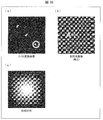
- the computer recorded the recorded image shown in FIG. 9A and performed a simulation for calculating the reproduced image by the reproducing device 11.
- Hologram recording is also performed by computer simulation.
- the recorded image is an image in which a hologram and a fluorescent image are superimposed.
- FIG. 9B shows an enlarged part of the recorded image.
- interference fringes holograms
- an image (Fourier transformed image) shown in FIG. 10A is obtained. Since the reflected light component is recorded as a hologram, it can be obtained separately from the fluorescent image component. An inverse Fourier transform is performed on the extracted spatial spectrum of the reflected light component (range in the lower right circle) from the Fourier transform image. From the inverse Fourier transformed image, a reflected light image (reproduced image) shown in FIG. 10B and a phase distribution shown in FIG. 10C are obtained. The phase distribution is represented by the phase of light using the height of the subject. Since the phase distribution includes information on a three-dimensional shape, the height information of the subject can be found from FIG.
- the zero-order diffracted light component is subtracted from the recorded image (FIG. 9A), and Fourier transform is performed to obtain the image of FIG.
- the distribution of the spatial spectrum at the center of the image changes. This indicates that only the spatial spectrum of the fluorescence image remains in the center due to the removal of the 0th-order diffracted light component. That is, by extracting only the spatial spectrum of the fluorescence image (the range of the circle in the center) from the Fourier transform image of FIG. 12A and performing the inverse Fourier transform on the extracted spatial spectrum, FIG. A fluorescent image (reproduced image) was obtained.
- the mean square error of the reconstructed image, the cross-correlation coefficient, and the signal-to-noise ratio for the original image were calculated.
- the mean square error of the reflected light image (reproduced image) was 8.6 ⁇ 10 ⁇ 2
- the cross-correlation coefficient was 1.00
- the signal-to-noise ratio was 56 dB.
- the mean square error of the fluorescent image (reproduced image) was 8.5 ⁇ 10 ⁇ 2
- the cross-correlation coefficient was 1.00
- the signal-to-noise ratio was 48 dB.
- the mean square error of the height distribution was 2.7 ⁇ 10 ⁇ 2 nm, the cross-correlation coefficient was 1.00, and the signal-to-noise ratio was 79 dB.
- FIG. 13 shows a reflected light image of a subject used for the simulation.
- 13A shows an image of the R (red) channel of the reflected light of the subject
- FIG. 13B shows an image of the G (green) channel of the reflected light of the subject
- FIG. 13C shows an image of the B (blue) channel of the reflected light of the subject
- FIG. 13D shows a reflected light image of the subject in which RGB colors are synthesized.
- FIG. 13D since each color is displayed as a single color (gray), the RB component of the color-combined image looks light, but FIG. 13D shows the image in which each color image is synthesized. It is. The same applies to other color-synthesized images.
- FIG. 14 shows a fluorescent image of the subject used for the simulation.
- 14A shows an image of the fluorescent R channel of the subject
- FIG. 14B shows an image of the fluorescent G channel of the subject
- FIG. 14C shows the fluorescent image of the subject.
- a B channel image is shown
- FIG. 14D shows a fluorescent image of a subject in which RGB colors are synthesized.
- FIG. 15 shows the height distribution of the subject.
- the height of the subject is expressed in light and dark.
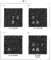
- the image shown in FIG. 16 is recognized, and the reflected light (object light) and fluorescence cannot be separated and identified.
- the simulation conditions are as follows.
- a color image sensor provided with a Bayer type color filter array is used as the imaging device 32.
- Each channel of the color filter array blocks light of two wavelengths out of the three wavelengths ⁇ 1, ⁇ 2, and ⁇ 3.
- the number of pixels of the image sensor is 2048 ⁇ 2048 (horizontal ⁇ vertical), and the pixel pitch is 1.4 ⁇ m in the horizontal direction and 1.4 ⁇ m in the vertical direction.
- the incident angle of the reference light is 6.05 ⁇ 10 ⁇ 2 rad for each of the x-axis and the y-axis.
- the intensity ratio between the object illumination light and the reference light is 1: 1.
- the intensity distribution image of the reference light of each wavelength is recorded independently for each wavelength before or after measurement.
- the intensity of the reflected light and fluorescence is 0 to 255 (the number of gradations is 256).
- the maximum height of the subject is 240 nm. It is assumed that reflected light is obtained by the light from each light source, and the phosphor is excited by light from two of the three light sources.
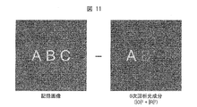
- the total energy of reflected light and fluorescence is less than the energy of object illumination light in each light source. Further, it is assumed that the reflected light and the fluorescence have the same wavelength. For example, it is assumed that the fluorescence generated by ⁇ 3 and the reflected light by ⁇ 1 include equal wavelength components. That is, it is assumed that the reflected light and the fluorescence cannot be separated by the wavelength filter.
- the object illumination light having the wavelength ⁇ 3 causes cyan fluorescence (letter “A”), yellow-green fluorescence (letter “0”), yellow fluorescence (letter “B”), and red fluorescence (letter “1”). “2”) occurs. It is assumed that yellow-green fluorescence, yellow fluorescence, and red fluorescence are generated by the object illumination light having the wavelength ⁇ 2. It is assumed that the object illumination light having the wavelength ⁇ 1 does not excite the phosphor.
- a computer recorded a RGB recorded image on each channel of the color image sensor and performed a simulation to calculate a reproduced image.
- Hologram recording is also performed by computer simulation.
- Each recorded image is an image in which a hologram and a fluorescent image are superimposed.
- the reflected light image, the fluorescence image, and the height distribution (phase distribution) are reproduced for each color from the recorded image of each color recorded by the RGB channels of the color image sensor by the same procedure as in the simulation 1.
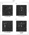
- the image shown in FIG. 17 was obtained from the recorded image of the R channel.
- the image shown in FIG. 18 was obtained from the recorded image of the G channel.
- the image shown in FIG. 19 was obtained from the recorded image of the B channel.
- FIG. 17A is a reflected light image (reproduced image) obtained from an R channel recorded image
- FIG. 17B is a fluorescence image (reproduced image) obtained from an R channel recorded image
- FIG. 17C shows the phase distribution obtained from the recorded image of the R channel.
- (A), (b), and (c) in FIG. 18 are a reflected light image (reproduced image), a fluorescent image (reproduced image), and a phase distribution, respectively, obtained from the G channel recorded image.
- (A), (b), and (c) in FIG. 19 are a reflected light image (reproduced image), a fluorescent image (reproduced image), and a phase distribution, respectively, obtained from the B channel recorded image.
- the center is displayed dark because the phase is folded (the phase changes from bright to dark at a position exceeding 2 ⁇ ). Even from these phase distributions, three-dimensional shape information can be obtained by phase connection.
- the mean square error, cross-correlation coefficient, and signal-to-noise ratio of the reconstructed image in each channel relative to the original image were calculated.
- the mean square error of the reflected light image of the R channel was 5.8 ⁇ 10 ⁇ 1
- the cross-correlation coefficient was 1.00
- the signal-to-noise ratio was 30 dB.
- the mean square error of the fluorescence image of the R channel was 9.6 ⁇ 10 ⁇ 1 , the cross-correlation coefficient was 1.00, and the signal-to-noise ratio was 29 dB.
- the mean square error of the reflected light image of the G channel was 6.0 ⁇ 10 ⁇ 1 , the cross-correlation coefficient was 1.00, and the signal-to-noise ratio was 31 dB.
- the mean square error of the G channel fluorescence image was 1.0, the cross-correlation coefficient was 1.00, and the signal-to-noise ratio was 30 dB.
- the mean square error of the reflected light image of the B channel was 6.9 ⁇ 10 ⁇ 1 , the cross-correlation coefficient was 1.00, and the signal-to-noise ratio was 30 dB.
- the mean square error of the B channel fluorescence image was 5.9 ⁇ 10 ⁇ 1 , the cross-correlation coefficient was 1.00, and the signal-to-noise ratio was 29 dB.
- the mean square error of the height distribution (phase distribution) was 3.4 ⁇ 10 ⁇ 1 nm, the cross-correlation coefficient was 1.00, and the signal-to-noise ratio was 58 dB.
- the subject (reflected light image, fluorescent image, and height distribution) used for the simulation is the same as that of simulation 1 (FIG. 7).
- the simulation conditions for recording are also the same as those for simulation 1. That is, the recorded image used for this simulation is the same as that of simulation 1 (FIG. 9).
- the computer recorded the recorded image shown in FIG. 9A and performed a simulation for calculating the reproduced image by the reproducing device 11.
- Hologram recording is also performed by computer simulation.
- the recorded image is an image in which a hologram and a fluorescent image are superimposed.
- the reproduction apparatus 11 obtained the complex amplitude (distribution) of the object light from the recorded image by using the spatial phase shift method (the above formulas (4) to (7)).
- 24A is a reflected light image (reproduced image) of a subject reproduced using the complex amplitude of the object light
- FIG. 24B is a phase distribution calculated using the complex amplitude of the object light. It is.
- the reflected light image and phase distribution components (object light information) are recorded as holograms, which can be separated from the fluorescence image and obtained by performing signal processing of the spatial phase shift method. Since the phase distribution includes three-dimensional shape information, the height information of the subject can be found from FIG.
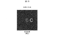
- the reproduction device 11 obtained a hologram image (hologram light intensity) from the complex amplitude of the object light, the intensity distribution of the reference light, and the phase of the reference light. Then, the fluorescence image (reproduction) shown in FIG. 25 was obtained by subtracting the hologram image from the recorded image. This corresponds to a process of removing the hologram component from the recorded image in which the hologram and the fluorescence image are superimposed. As described above, the reproduction device 11 can reproduce the reflected light image (reproduced image of object light) and the fluorescent image separately from the recorded image in which the hologram and the fluorescent image are superimposed.
- the mean square error of the reconstructed image, the cross-correlation coefficient, and the signal-to-noise ratio for the original image were calculated.
- the mean square error of the reflected light image was 5.8 ⁇ 10 ⁇ 1
- the cross-correlation coefficient was 0.999
- the signal-to-noise ratio was 39 dB.
- the mean square error of the fluorescence image was 7.5 ⁇ 10 ⁇ 1
- the cross-correlation coefficient was 0.999
- the signal-to-noise ratio was 29 dB.
- the mean square error of the height distribution was 3.4 ⁇ 10 ⁇ 1 nm, the cross-correlation coefficient was 1.00, and the signal-to-noise ratio was 57 dB.
- an instantaneous reflected light image, fluorescent image, and three-dimensional information of a dynamic object can be obtained with high accuracy by a single light source recording apparatus.
- the processing of the playback device 11 may be realized by a logic circuit (hardware) formed in an integrated circuit (IC chip) or the like, or may be realized by software using a CPU (Central Processing Unit).
- a logic circuit hardware formed in an integrated circuit (IC chip) or the like
- a CPU Central Processing Unit
- the playback device 11 includes a CPU that executes instructions of a program that is software that implements each function, a ROM (Read Only Memory) in which the program and various data are recorded so as to be readable by a computer (or CPU), or A storage device (these are referred to as “recording media”), a RAM (Random Access Memory) for expanding the program, and the like are provided.
- recording media a “non-temporary tangible medium” such as a tape, a disk, a card, a semiconductor memory, a programmable logic circuit, or the like can be used.
- the program may be supplied to the computer via an arbitrary transmission medium (such as a communication network or a broadcast wave) that can transmit the program.
- a transmission medium such as a communication network or a broadcast wave
- the present invention can also be realized in the form of a data signal embedded in a carrier wave in which the program is embodied by electronic transmission.
- a digital holography recording device includes a light source that irradiates an object with object illumination light so that object light is generated, a hologram that is formed by interference between reference light and the object light, An imaging device that captures an image, and the object illumination light also excites a phosphor included in the object.
- both the hologram and the fluorescence image can be simultaneously captured in a state where they can be separated and reproduced.
- the object illumination light emitted from one light source serves both as a role for generating the object light and a role as excitation light for exciting the phosphor. Therefore, the digital holography recording apparatus is advantageous for downsizing.
- the light source may be configured to emit the object illumination light having a single wavelength.
- the imaging device may be configured to capture an image in which a hologram formed by interference between the object light and the reference light and a fluorescent image emitted from the phosphor are superimposed.
- It may be configured to include an imaging optical element that forms an image of the fluorescence on the imaging surface of the imaging device.
- the fluorescent image formed from the recorded image can be reproduced.
- the imaging device may be a monochrome imaging device that does not use a color filter.
- object light and fluorescence can be separated and reproduced without using a color filter.
- the imaging apparatus can record a bright image without loss of the amount of fluorescent light due to the color filter.
- the light source is a first light source that irradiates the object with object illumination light of a first wavelength, and the object illumination of the second wavelength is generated on the object so that object light of a second wavelength different from the first wavelength is generated.
- a second light source that emits light; and the imaging device captures the first wavelength hologram, the second wavelength hologram, and the fluorescence image, and the first wavelength object illumination light and the first wavelength hologram Both the object illumination lights of the second wavelength may be configured to excite the phosphor.
- the phosphor can be excited by object illumination light having two wavelengths, the intensity of the fluorescence emitted by the phosphor can be enhanced.
- the optical axis of the reference light incident on the imaging device may be inclined with respect to the optical axis of the object light incident on the imaging device.
- the spatial spectrum of the object light wave can be accurately extracted on the spatial frequency plane of the recorded image. Therefore, the accuracy of reproducing object light can be increased.
- a digital holography recording apparatus includes a light source that irradiates an object with object illumination light, a hologram that is formed by interference between reference light and object light from the object, and the object.
- An imaging device that captures an image superimposed with an image of fluorescence emitted from the phosphor.
- both the hologram and the fluorescence image can be simultaneously captured in a state where they can be separated and reproduced.
- a digital holography reproducing device uses a spatial phase shift method from an image in which a hologram formed by interference of reference light and object light and a fluorescence image are superimposed.
- a spatial phase shift method uses a spatial phase shift method from an image in which a hologram formed by interference of reference light and object light and a fluorescence image are superimposed.
- object light information and fluorescence information can be separated at high speed from an image in which a hologram and a fluorescence image are superimposed.
- a digital holography reproducing device performs Fourier transform on an image in which a hologram formed by interference between reference light and object light and a fluorescence image are superimposed, and the Fourier transformed image
- the spatial spectrum of the object light is extracted, and the extracted spatial spectrum of the object light is subjected to inverse Fourier transform to obtain a complex amplitude of the object light, and a zero-order diffracted light component is obtained from the complex amplitude of the object light.
- the zero-order diffracted light component is removed from the Fourier-transformed image, and the spatial spectrum of the fluorescence image is extracted from the Fourier-transformed image from which the zero-order diffracted light component is removed.
- object light information and fluorescence information can be accurately separated from an image in which a hologram and a fluorescence image are superimposed.
- the digital holography reproducing device may be configured to obtain the fluorescence image by performing inverse Fourier transform on the extracted spatial spectrum of the fluorescence image.
- the object light and the fluorescence image can be separated and reproduced from the image in which the hologram and the fluorescence image are superimposed.
- a digital holography reproducing device performs Fourier transform on an image in which a hologram formed by interference between reference light and object light and a fluorescence image are superimposed, and the Fourier transformed image Extracting the spatial spectrum of the object light, inverse Fourier transforming the extracted spatial spectrum of the object light, obtaining the complex amplitude of the object light, and obtaining the intensity of the hologram from the complex amplitude of the object light
- the fluorescence image is obtained by removing the hologram from the image.
- a digital holography recording method generates object light by irradiating an object with illumination light emitted from a light source, and excites a phosphor included in the object with the object illumination light. And a step of capturing a hologram formed by interference between the reference light and the object light, and a fluorescence image emitted from the phosphor.
- a digital holography recording method includes a step of irradiating an object with object illumination light, a hologram formed by interference of reference light and object light from the object, and the object Capturing an image on which a fluorescent image emitted from the phosphor is superimposed.
- a digital holography reproduction method includes a method in which a spatial phase shift method is used to generate an image obtained by superimposing a hologram formed by interference between reference light and object light and a fluorescence image. Obtaining a complex amplitude of the light; obtaining an intensity of the hologram from the complex amplitude of the object light; and obtaining the fluorescence image by removing the hologram from the image.
- a digital holography reproduction method includes a step of Fourier transforming an image in which a hologram formed by interference between reference light and object light and a fluorescent image are superimposed, Extracting the spatial spectrum of the object light from the image, obtaining the complex amplitude of the object light by performing inverse Fourier transform on the extracted spatial spectrum of the object light, and from the complex amplitude of the object light Obtaining a zero-order diffracted light component, removing the zero-order diffracted light component from the Fourier-transformed image, and extracting the spatial spectrum of the fluorescence image from the Fourier-transformed image from which the zero-order diffracted light component has been removed. Steps.
- a digital holography reproduction method includes a step of Fourier transforming an image in which a hologram formed by interference between reference light and object light and a fluorescent image are superimposed, Extracting the spatial spectrum of the object light from the image, obtaining the complex amplitude of the object light by performing inverse Fourier transform on the extracted spatial spectrum of the object light, and from the complex amplitude of the object light Obtaining the intensity of the hologram, and removing the hologram from the image to obtain the fluorescence image.
- the present invention can be used for a digital holography apparatus, a high-speed 3D camera, a fluorescent three-dimensional microscope, and the like.
- Digital holography device 10 20, 30 Recording device (digital holography recording device) 11 Playback device (digital holography playback device) 12, 32 Imaging device 13 Subject (object) 14 Phosphor 15 Imaging element (imaging optical element) LS1 to LS3 Laser light source (first light source, second light source)
Abstract
Description
本実施形態は、物体光の情報と蛍光の情報とを単一露光で同時に記録するデジタルホログラフィ装置に関する。そして、デジタルホログラフィ装置は、記録したホログラムを用いて、物体光の情報と蛍光の情報とを互いに分離して再生することができる。
The present embodiment relates to a digital holography apparatus that simultaneously records object light information and fluorescence information with a single exposure. The digital holography apparatus can reproduce the object light information and the fluorescence information separately from each other using the recorded hologram.
図1は、本実施形態のデジタルホログラフィ装置1の構成を示す模式図である。デジタルホログラフィ装置1は、軸外し型(off-axis型)のデジタルホログラフィ装置である。デジタルホログラフィ装置1は、記録装置10(デジタルホログラフィ記録装置)と再生装置11(デジタルホログラフィ再生装置)とを備える。記録装置10は、撮像装置12、波長λ1のレーザ光源LS1(第1光源)、および光学系を備える。再生装置11は、コンピュータ等の計算機によって構成することができる。なお、レーザ光としては、可視光のみならず、不可視光(赤外線、紫外線、X線等)も利用することができる。 (Configuration of digital holography apparatus 1)
FIG. 1 is a schematic diagram showing a configuration of a
レーザ光源LS1から出射された波長λ1のレーザ光は、ビームスプリッタBS1によって参照光と物体照明光とに分けられる。 (Object light, reference light and fluorescence)
The laser light having the wavelength λ1 emitted from the laser light source LS1 is divided into reference light and object illumination light by the beam splitter BS1.
図2は、本実施形態の再生装置11が行う再生処理のフローを示す図である。再生装置11は、撮像装置12によって記録された画像(ホログラム+蛍光)を用いて、被写体13の像の再生および蛍光の像の再生を行う。ただし、記録された画像は、物体光の情報(すなわち被写体13の3次元形状情報)を含むホログラムと、蛍光とが重畳した画像であるので、そのままでは公知のデジタルホログラフィ技術で再生することができない。 (Configuration of playback device 11)
FIG. 2 is a diagram showing a flow of a reproduction process performed by the
Ih=|O|2+|R|2+2|O||R|cosφ (1)
ここで、|O|は物体光の振幅、|R|は参照光の振幅、|O|2は物体光の強度、|R|2は参照光の強度、φは参照光に対する物体光の位相差である。|O|、|R|、およびφは、画素毎に異なり得る。なお、参照光はレーザ光を引き伸ばした平面波であるので、参照光の強度は一様な値または所定の分布(例えばガウス分布)の値であると仮定(推定)してもよい。なお、より精度よく像を再生するために、事前または事後に参照光のみの強度分布を測定してもよい。参照光の強度分布を測定することは再生の精度を上げるためのキャリブレーションに相当する。それゆえ|R|2は既知の値として扱うことができる。 Here, the value of each pixel of the recorded image is the sum of the light intensity Ih of the hologram and the light intensity If of the fluorescence. Ih and If are different for each pixel. Since the fluorescence is imaged on the imaging surface, the light intensity If of the fluorescence represents the distribution of fluorescence viewed from the
Ih = | O | 2 + | R | 2 +2 | O || R | cosφ (1)
Where | O | is the amplitude of the object light, | R | is the amplitude of the reference light, | O | 2 is the intensity of the object light, | R | 2 is the intensity of the reference light, and φ is the position of the object light with respect to the reference light. It is a phase difference. | O |, | R |, and φ may vary from pixel to pixel. Since the reference light is a plane wave obtained by stretching the laser light, the intensity of the reference light may be assumed (estimated) to be a uniform value or a predetermined distribution (for example, Gaussian distribution). In order to reproduce an image with higher accuracy, the intensity distribution of only the reference light may be measured in advance or after the fact. Measuring the intensity distribution of the reference light corresponds to calibration for increasing the reproduction accuracy. Therefore, | R | 2 can be treated as a known value.
本実施形態では、複数の波長のレーザ光源を用いる場合について説明する。 [Embodiment 2]
In this embodiment, a case where laser light sources having a plurality of wavelengths are used will be described.
図4は、本実施形態のデジタルホログラフィ装置2の構成を示す模式図である。デジタルホログラフィ装置2は、軸外し型(off-axis型)のデジタルホログラフィ装置である。デジタルホログラフィ装置2は、記録装置20(デジタルホログラフィ記録装置)と再生装置11とを備える。記録装置20は、撮像装置12、波長λ1のレーザ光源LS1、波長λ2のレーザ光源LS2(第1光源)、波長λ3のレーザ光源LS3(第2光源)、および光学系を備える。 (Recording of object light and fluorescence)
FIG. 4 is a schematic diagram showing the configuration of the
図5は、記録された画像を2次元フーリエ変換したものを概略的に示す図である。図5において、横軸はx軸の空間周波数fxを示し、縦軸はy軸の空間周波数fyを示す。 (Reproduction of object light and fluorescence)
FIG. 5 is a diagram schematically showing a two-dimensional Fourier transform of a recorded image. In FIG. 5, the horizontal axis represents the x-axis spatial frequency fx, and the vertical axis represents the y-axis spatial frequency fy.
本実施形態では、複数の波長のレーザ光源およびカラー撮像装置を用いる場合について説明する。 [Embodiment 3]
In this embodiment, a case where a laser light source having a plurality of wavelengths and a color imaging device are used will be described.
図6は、本実施形態のデジタルホログラフィ装置3の構成を示す模式図である。デジタルホログラフィ装置3は、軸外し型(off-axis型)のデジタルホログラフィ装置である。デジタルホログラフィ装置3は、記録装置30(デジタルホログラフィ記録装置)と再生装置11とを備える。記録装置30は、撮像装置32、波長λ1のレーザ光源LS1、波長λ2のレーザ光源LS2、波長λ3のレーザ光源LS3、および光学系を備える。 (Recording of object light and fluorescence)
FIG. 6 is a schematic diagram showing a configuration of the
本実施形態では、フーリエ変換を用いない再生方法について説明する。本実施形態の再生装置11は、参照光の位相が空間的に異なる(撮像面の画素毎に参照光の位相が異なる)場合に、空間的位相シフト法を用いて物体光の複素振幅を求める。なお、記録装置は、実施形態1と同様の構成とすることができる。以下に具体的に説明する。 [Embodiment 4]
In this embodiment, a reproduction method that does not use Fourier transform will be described. The reproducing
図20の(a)は、撮像装置の画素と参照光との関係を説明する模式図であり、図20の(b)は撮像装置の撮像面(または記録画像)の一部における参照光の位相シフト量を説明する模式図である。図20の(b)の1つの矩形は1つの画素に対応する。 (Recording device)
20A is a schematic diagram for explaining the relationship between the pixels of the imaging device and the reference light, and FIG. 20B is a diagram of reference light on a part of the imaging surface (or recorded image) of the imaging device. It is a schematic diagram explaining the amount of phase shifts. One rectangle in FIG. 20B corresponds to one pixel.
図21は、本実施形態の再生装置11が行う再生処理のフローを示す図である。図22は、再生処理のフローの概要を示す図である。図22における矩形は一部を拡大して示される画像の画素を表し、矩形の中の数値は位相シフト量を示す。ここでは、x軸方向(水平方向)の隣接画素において、位相シフト量の差が2π/3である場合を例にして説明する。記録画像には、物体光および位相がシフトした参照光が干渉したホログラムと、蛍光の像とが重畳して記録されている。 (Playback device)
FIG. 21 is a diagram showing a flow of a reproduction process performed by the
上記では、画素を抽出・補間する場合を例に挙げて説明した。さらなる再生処理負荷の低減を目的として、補間処理を行わずに物体光と蛍光の像とを分離・再生する例について説明する。 (Modification)
In the above description, the case of extracting and interpolating pixels has been described as an example. An example of separating and reproducing the object light and the fluorescence image without performing the interpolation process for the purpose of further reducing the reproduction processing load will be described.
I(x,y)=If(x,y)+Ih(x,y) (2)
Ih(x,y)=|Uo(x,y)|2+|Ur(x,y)|2
+2Ao(x,y)Ar(x,y)cos{φo(x,y)-φr(x,y)} (3)
ここで、物体光の複素振幅をUo(x,y)=Ao(x,y)exp{jφo(x,y)}とし、参照光の複素振幅をUr(x,y)=Ar(x,y)exp{jφr(x,y)}とした。Ao、Arは振幅を表し、φo、φrは位相を表す。jは虚数単位である。Mをx軸方向の画素数、Nをy軸方向の画素数とし、0≦x≦M-1、0≦y≦N-1とする(x、yは画素番地(整数))。 The pixel value I (x, y) of the recorded image is the sum of the light intensity If (x, y) of the fluorescence image and the light intensity Ih (x, y) of the hologram. x and y indicate pixel coordinates.
I (x, y) = If (x, y) + Ih (x, y) (2)
Ih (x, y) = | Uo (x, y) | 2 + | Ur (x, y) | 2
+ 2Ao (x, y) Ar (x, y) cos {φo (x, y) −φr (x, y)} (3)
Here, the complex amplitude of the object beam is Uo (x, y) = Ao (x, y) exp {jφo (x, y)}, and the complex amplitude of the reference beam is Ur (x, y) = Ar (x, y) exp {jφr (x, y)}. Ao and Ar represent amplitudes, and φo and φr represent phases. j is an imaginary unit. M is the number of pixels in the x-axis direction, N is the number of pixels in the y-axis direction, and 0 ≦ x ≦ M−1 and 0 ≦ y ≦ N−1 (x and y are pixel addresses (integers)).
・(x+y)÷4の余りが0のとき、
Uo(x,y)=
[{I(x,y)-I(x+1,y+1)}+j{I(x+1,y)+I(x,y+1)-I(x,y)-I(x+1,y+1)}]
/{4Ar(x,y)} (4)
・(x+y)÷4の余りが1のとき、
Uo(x,y)=
[-{I(x+1,y)+I(x,y+1)-I(x,y)-I(x+1,y+1)}+j{I(x,y)-I(x+1,y+1)}]
/{4Ar(x,y)} (5)
・(x+y)÷4の余りが2のとき、
Uo(x,y)=
[-{I(x,y)-I(x+1,y+1)}-j{I(x+1,y)+I(x,y+1)-I(x,y)-I(x+1,y+1)}]
/{4Ar(x,y)} (6)
・(x+y)÷4の余りが3のとき、
Uo(x,y)=
[{I(x+1,y)+I(x,y+1)-I(x,y)-I(x+1,y+1)}-j{I(x,y)-I(x+1,y+1)}]
/{4Ar(x,y)} (7)
となる。これによって、再生装置11は、物体光の複素振幅を求めることができる。再生装置11は、物体光の複素振幅分布と既知の参照光の強度分布と参照光の位相シフト量(参照光の位相)とから、ホログラムの光強度Ihの分布を求める。式(2)より、再生装置11は、記録画像の画素値Iからホログラムの光強度Ihを減算することにより、蛍光の像の光強度Ifを求める。また、参照光の強度分布にむらがある場合、記録画像から参照光の強度分布を減算した後に空間的位相シフト法の計算をしてもよい。これにより、参照光の強度のむらによる出力される像の画質劣化の問題を緩和することができる。 The reproducing
・ When the remainder of (x + y) ÷ 4 is 0,
Uo (x, y) =
[{I (x, y) −I (x + 1, y + 1)} + j {I (x + 1, y) + I (x, y + 1) −I (x, y) −I (x + 1, y + 1)}]
/ {4Ar (x, y)} (4)
・ When the remainder of (x + y) ÷ 4 is 1,
Uo (x, y) =
[− {I (x + 1, y) + I (x, y + 1) −I (x, y) −I (x + 1, y + 1)} + j {I (x, y) −I (x + 1, y + 1)}]
/ {4Ar (x, y)} (5)
・ When the remainder of (x + y) ÷ 4 is 2,
Uo (x, y) =
[− {I (x, y) −I (x + 1, y + 1)} − j {I (x + 1, y) + I (x, y + 1) −I (x, y) −I ( x + 1, y + 1)}]
/ {4Ar (x, y)} (6)
・ When the remainder of (x + y) ÷ 4 is 3,
Uo (x, y) =
[{I (x + 1, y) + I (x, y + 1) −I (x, y) −I (x + 1, y + 1)} − j {I (x, y) −I (x + 1, y + 1)}]
/ {4Ar (x, y)} (7)
It becomes. Thereby, the reproducing
本発明の実施形態1に基づくホログラムの記録および再生のシミュレーション結果について説明する。ここでは、図1に示すデジタルホログラフィ装置1を用いると仮定する。 [Simulation 1]
A simulation result of hologram recording and reproduction based on
本発明の実施形態3に基づくホログラムの記録および再生のシミュレーション結果について説明する。ここでは、図6に示すデジタルホログラフィ装置3を使用すると仮定する。 [Simulation 2]
A simulation result of hologram recording and reproduction based on
本発明の実施形態4に基づくホログラムの記録および再生のシミュレーション結果について説明する。ここでは、図1に示すデジタルホログラフィ装置1を使用すると仮定する。 [Simulation 3]
A simulation result of hologram recording and reproduction based on Embodiment 4 of the present invention will be described. Here, it is assumed that the
再生装置11の処理は、集積回路(ICチップ)等に形成された論理回路(ハードウェア)によって実現してもよいし、CPU(Central Processing Unit)を用いてソフトウェアによって実現してもよい。 [Example of software implementation]
The processing of the
本発明の一態様に係るデジタルホログラフィ記録装置は、物体光が生じるように物体に物体照明光を照射する光源と、参照光と前記物体光とが干渉することにより形成されるホログラムと、蛍光の像とを撮像する撮像装置とを備え、前記物体照明光はまた、前記物体に含まれる蛍光体を励起する。 [Summary]
A digital holography recording device according to one embodiment of the present invention includes a light source that irradiates an object with object illumination light so that object light is generated, a hologram that is formed by interference between reference light and the object light, An imaging device that captures an image, and the object illumination light also excites a phosphor included in the object.
10、20、30 記録装置(デジタルホログラフィ記録装置)
11 再生装置(デジタルホログラフィ再生装置)
12、32 撮像装置
13 被写体(物体)
14 蛍光体
15 結像素子(結像光学素子)
LS1~LS3 レーザ光源(第1光源、第2光源) 1-3
11 Playback device (digital holography playback device)
12, 32
14
LS1 to LS3 Laser light source (first light source, second light source)
Claims (17)
- 物体光が生じるように物体に物体照明光を照射する光源と、
参照光と前記物体光とが干渉することにより形成されるホログラムと、蛍光の像とを撮像する撮像装置とを備え、
前記物体照明光はまた、前記物体に含まれる蛍光体を励起することを特徴とするデジタルホログラフィ記録装置。 A light source that irradiates the object with illumination light so that the object light is generated;
An imaging device that captures a hologram formed by interference between reference light and the object light, and a fluorescence image;
The digital holography recording apparatus, wherein the object illumination light also excites a phosphor contained in the object. - 前記光源は、単一波長の前記物体照明光を出射することを特徴とする請求項1に記載のデジタルホログラフィ記録装置。 The digital holography recording apparatus according to claim 1, wherein the light source emits the object illumination light having a single wavelength.
- 前記撮像装置は、前記物体光と参照光とが干渉することにより形成されるホログラムと、前記蛍光体が発する蛍光の像とが重畳した画像を撮像することを特徴とする請求項1または2に記載のデジタルホログラフィ記録装置。 The image pickup apparatus picks up an image in which a hologram formed by interference between the object light and reference light and a fluorescent image emitted from the phosphor are superimposed on each other. The digital holographic recording device described.
- 前記蛍光を前記撮像装置の撮像面に結像させる結像光学素子を備えることを特徴とする請求項3に記載のデジタルホログラフィ記録装置。 The digital holography recording apparatus according to claim 3, further comprising an imaging optical element that forms an image of the fluorescence on an imaging surface of the imaging apparatus.
- 前記撮像装置は、カラーフィルタを用いないモノクロ撮像装置であることを特徴とする請求項1から4のいずれか一項に記載のデジタルホログラフィ記録装置。 5. The digital holography recording apparatus according to claim 1, wherein the imaging apparatus is a monochrome imaging apparatus that does not use a color filter.
- 前記光源は、前記物体に第1波長の物体照明光を照射する第1光源であり、
前記第1波長とは異なる第2波長の物体光が生じるように前記物体に前記第2波長の物体照明光を照射する第2光源を備え、
前記撮像装置は、前記第1波長のホログラムと、前記第2波長のホログラムと、前記蛍光の像とを撮像し、
前記第1波長の物体照明光および前記第2波長の物体照明光の両方は、前記蛍光体を励起することを特徴とする請求項1から5のいずれか一項に記載のデジタルホログラフィ記録装置。 The light source is a first light source that irradiates the object with object illumination light having a first wavelength;
A second light source for irradiating the object illumination light of the second wavelength to the object so that object light of a second wavelength different from the first wavelength is generated;
The imaging device captures the hologram of the first wavelength, the hologram of the second wavelength, and the fluorescence image,
6. The digital holography recording apparatus according to claim 1, wherein both the object illumination light having the first wavelength and the object illumination light having the second wavelength excite the phosphor. - 前記撮像装置に入射する前記物体光の光軸に対して、前記撮像装置に入射する前記参照光の光軸は傾いていることを特徴とする請求項1から6のいずれか一項に記載のデジタルホログラフィ記録装置。 7. The optical axis of the reference light incident on the imaging device is tilted with respect to the optical axis of the object light incident on the imaging device. 7. Digital holography recording device.
- 物体に物体照明光を照射する光源と、
参照光と前記物体からの物体光とが干渉することにより形成されるホログラムと、前記物体に含まれる蛍光体が発する蛍光の像とが重畳した画像を撮像する撮像装置とを備えることを特徴とするデジタルホログラフィ記録装置。 A light source that irradiates an object with object illumination light;
An imaging device that captures an image in which a hologram formed by interference between reference light and object light from the object and a fluorescent image emitted by a phosphor included in the object are superimposed on each other; Digital holography recording device. - 参照光と物体光とが干渉することにより形成されるホログラムと、インコヒーレント光の像とが重畳した画像から、空間的位相シフト法を用いて前記物体光の複素振幅を求め、
前記物体光の複素振幅から前記ホログラムの強度を求め、
前記画像から前記ホログラムを除去することにより、前記インコヒーレント光の像を得ることを特徴とするデジタルホログラフィ再生装置。 From the image formed by superimposing the hologram formed by the interference of the reference light and the object light and the image of the incoherent light, the complex amplitude of the object light is obtained using a spatial phase shift method,
Obtain the intensity of the hologram from the complex amplitude of the object light,
A digital holography reproducing apparatus, wherein an image of the incoherent light is obtained by removing the hologram from the image. - 参照光と物体光とが干渉することにより形成されるホログラムと、インコヒーレント光の像とが重畳した画像をフーリエ変換し、
フーリエ変換された前記画像から、前記物体光の空間スペクトルを抽出し、
抽出された前記物体光の空間スペクトルを逆フーリエ変換することで、前記物体光の複素振幅を求め、
前記物体光の複素振幅から0次回折光成分を求め、フーリエ変換された前記画像から0次回折光成分を除去し、
0次回折光成分が除去されたフーリエ変換された前記画像から、前記インコヒーレント光の像の空間スペクトルを抽出することを特徴とするデジタルホログラフィ再生装置。 Fourier transform the image formed by superimposing the hologram formed by the interference of the reference light and the object light and the image of the incoherent light,
Extracting the spatial spectrum of the object light from the Fourier transformed image,
By performing inverse Fourier transform on the extracted spatial spectrum of the object light, the complex amplitude of the object light is obtained,
Obtaining a zero-order diffracted light component from the complex amplitude of the object light, removing the zero-order diffracted light component from the Fourier-transformed image;
A digital holography reproducing apparatus, wherein a spatial spectrum of the image of the incoherent light is extracted from the Fourier-transformed image from which the 0th-order diffracted light component is removed. - 抽出された前記インコヒーレント光の像の空間スペクトルを逆フーリエ変換することで、前記インコヒーレント光の像を得ることを特徴とする請求項10に記載のデジタルホログラフィ再生装置。 The digital holography reproducing device according to claim 10, wherein an image of the incoherent light is obtained by performing inverse Fourier transform on a spatial spectrum of the extracted image of the incoherent light.
- 参照光と物体光とが干渉することにより形成されるホログラムと、インコヒーレント光の像とが重畳した画像をフーリエ変換し、
フーリエ変換された前記画像から、前記物体光の空間スペクトルを抽出し、
抽出された前記物体光の空間スペクトルを逆フーリエ変換することで、前記物体光の複素振幅を求め、
前記物体光の複素振幅から前記ホログラムの強度を求め、前記画像から前記ホログラムを除去することにより、前記インコヒーレント光の像を得ることを特徴とするデジタルホログラフィ再生装置。 Fourier transform the image formed by superimposing the hologram formed by the interference of the reference light and the object light and the image of the incoherent light,
Extracting the spatial spectrum of the object light from the Fourier transformed image,
By performing inverse Fourier transform on the extracted spatial spectrum of the object light, the complex amplitude of the object light is obtained,
A digital holography reproduction device characterized in that an image of the incoherent light is obtained by obtaining an intensity of the hologram from a complex amplitude of the object light and removing the hologram from the image. - 光源から出射された物体照明光を物体に照射することにより物体光を生じさせるとともに、前記物体照明光によって前記物体に含まれる蛍光体を励起するステップと、
参照光と前記物体光とが干渉することにより形成されるホログラムと、前記蛍光体が発する蛍光の像とを撮像するステップとを含むことを特徴とするデジタルホログラフィ記録方法。 Irradiating the object with the object illumination light emitted from the light source to generate the object light, and exciting the phosphor included in the object with the object illumination light;
A digital holography recording method, comprising: a step of capturing a hologram formed by interference between reference light and the object light; and a fluorescence image emitted from the phosphor. - 物体照明光を物体に照射するステップと、
参照光と前記物体からの物体光とが干渉することにより形成されるホログラムと、前記物体に含まれる蛍光体が発する蛍光の像とが重畳した画像を撮像するステップとを含むことを特徴とするデジタルホログラフィ記録方法。 Irradiating an object with illumination light;
And a step of capturing an image formed by superimposing a hologram formed by interference between reference light and object light from the object, and a fluorescence image emitted from a phosphor included in the object. Digital holography recording method. - 参照光と物体光とが干渉することにより形成されるホログラムと、インコヒーレント光の像とが重畳した画像から、空間的位相シフト法を用いて前記物体光の複素振幅を求めるステップと、
前記物体光の複素振幅から前記ホログラムの強度を求めるステップと、
前記画像から前記ホログラムを除去することにより、前記インコヒーレント光の像を得るステップとを含むことを特徴とするデジタルホログラフィ再生方法。 Obtaining a complex amplitude of the object light using a spatial phase shift method from an image formed by superimposing a hologram formed by interference between the reference light and the object light and an image of the incoherent light;
Obtaining the intensity of the hologram from the complex amplitude of the object light;
And removing the hologram from the image to obtain an image of the incoherent light. - 参照光と物体光とが干渉することにより形成されるホログラムと、インコヒーレント光の像とが重畳した画像をフーリエ変換するステップと、
フーリエ変換された前記画像から、前記物体光の空間スペクトルを抽出するステップと、
抽出された前記物体光の空間スペクトルを逆フーリエ変換することで、前記物体光の複素振幅を求めるステップと、
前記物体光の複素振幅から0次回折光成分を求め、フーリエ変換された前記画像から0次回折光成分を除去するステップと、
0次回折光成分が除去されたフーリエ変換された前記画像から、前記インコヒーレント光の像の空間スペクトルを抽出するステップとを含むことを特徴とするデジタルホログラフィ再生方法。 Fourier transforming an image in which a hologram formed by interference between reference light and object light and an image of incoherent light are superimposed;
Extracting a spatial spectrum of the object light from the Fourier transformed image;
Obtaining a complex amplitude of the object light by performing an inverse Fourier transform on the extracted spatial spectrum of the object light; and
Obtaining a zero-order diffracted light component from the complex amplitude of the object light and removing the zero-order diffracted light component from the Fourier-transformed image;
Extracting the spatial spectrum of the image of the incoherent light from the Fourier-transformed image from which the 0th-order diffracted light component has been removed. - 参照光と物体光とが干渉することにより形成されるホログラムと、インコヒーレント光の像とが重畳した画像をフーリエ変換するステップと、
フーリエ変換された前記画像から、前記物体光の空間スペクトルを抽出するステップと、
抽出された前記物体光の空間スペクトルを逆フーリエ変換することで、前記物体光の複素振幅を求めるステップと、
前記物体光の複素振幅から前記ホログラムの強度を求め、前記画像から前記ホログラムを除去することにより、前記インコヒーレント光の像を得るステップとを含むことを特徴とするデジタルホログラフィ再生方法。 Fourier transforming an image in which a hologram formed by interference between reference light and object light and an image of incoherent light are superimposed;
Extracting a spatial spectrum of the object light from the Fourier transformed image;
Obtaining a complex amplitude of the object light by performing an inverse Fourier transform on the extracted spatial spectrum of the object light; and
Obtaining the intensity of the hologram from the complex amplitude of the object light, and removing the hologram from the image, thereby obtaining an image of the incoherent light.
Priority Applications (3)
| Application Number | Priority Date | Filing Date | Title |
|---|---|---|---|
| EP16743469.5A EP3252537A4 (en) | 2015-01-28 | 2016-01-28 | Digital holography recording device, digital holography playback device, digital holography recording method, and digital holography playback method |
| US15/546,651 US10006860B2 (en) | 2015-01-28 | 2016-01-28 | Digital holography recording device, digital holography playback device, digital holography recording method, and digital holography playback method |
| JP2016572142A JP6628103B2 (en) | 2015-01-28 | 2016-01-28 | Digital holographic recording device, digital holographic reproducing device, digital holographic recording method, and digital holographic reproducing method |
Applications Claiming Priority (2)
| Application Number | Priority Date | Filing Date | Title |
|---|---|---|---|
| JP2015014802 | 2015-01-28 | ||
| JP2015-014802 | 2015-01-28 |
Publications (1)
| Publication Number | Publication Date |
|---|---|
| WO2016121866A1 true WO2016121866A1 (en) | 2016-08-04 |
Family
ID=56543471
Family Applications (1)
| Application Number | Title | Priority Date | Filing Date |
|---|---|---|---|
| PCT/JP2016/052487 WO2016121866A1 (en) | 2015-01-28 | 2016-01-28 | Digital holography recording device, digital holography playback device, digital holography recording method, and digital holography playback method |
Country Status (4)
| Country | Link |
|---|---|
| US (1) | US10006860B2 (en) |
| EP (1) | EP3252537A4 (en) |
| JP (1) | JP6628103B2 (en) |
| WO (1) | WO2016121866A1 (en) |
Cited By (2)
| Publication number | Priority date | Publication date | Assignee | Title |
|---|---|---|---|---|
| JP2018137029A (en) * | 2017-02-24 | 2018-08-30 | 学校法人東京理科大学 | Hologram recording and reproducing device |
| CN115984314A (en) * | 2022-11-25 | 2023-04-18 | 哈尔滨理工大学 | Image edge detection method and system based on second-order differential of computer generated hologram |
Families Citing this family (5)
| Publication number | Priority date | Publication date | Assignee | Title |
|---|---|---|---|---|
| JP6791645B2 (en) * | 2016-03-29 | 2020-11-25 | 本田技研工業株式会社 | Optical communication equipment, optical communication system, and optical communication method |
| CN105954992B (en) * | 2016-07-22 | 2018-10-30 | 京东方科技集团股份有限公司 | Display system and display methods |
| CN110030944B (en) * | 2019-04-03 | 2021-09-21 | 中国科学院光电技术研究所 | Large-gradient free-form surface measuring method |
| WO2021121733A1 (en) | 2019-12-17 | 2021-06-24 | Asml Netherlands B.V. | Dark field digital holographic microscope and associated metrology method |
| EP3839635A1 (en) | 2019-12-17 | 2021-06-23 | ASML Netherlands B.V. | Dark field digital holographic microscope and associated metrology method |
Citations (4)
| Publication number | Priority date | Publication date | Assignee | Title |
|---|---|---|---|---|
| JP2004538451A (en) * | 2001-06-29 | 2004-12-24 | ユニベルスィテ リーブル ドゥ ブリュッセル | Method and device for obtaining a sample by three-dimensional microscopy |
| JP2013507647A (en) * | 2009-10-08 | 2013-03-04 | ユニヴェルシテ リブル ドゥ ブリュッセル | Off-axis interferometer |
| JP2013508775A (en) * | 2009-10-20 | 2013-03-07 | ザ リージェンツ オブ ザ ユニバーシティ オブ カリフォルニア | On-chip incoherent lens-free holography and microscopy |
| JP2013054336A (en) * | 2011-09-02 | 2013-03-21 | Mitsutoyo Corp | Apparatus for exact reconstruction of object wave in off-axis digital holography |
Family Cites Families (10)
| Publication number | Priority date | Publication date | Assignee | Title |
|---|---|---|---|---|
| US6512385B1 (en) * | 1999-07-26 | 2003-01-28 | Paul Pfaff | Method for testing a device under test including the interference of two beams |
| US7217573B1 (en) | 1999-10-05 | 2007-05-15 | Hitachi, Ltd. | Method of inspecting a DNA chip |
| JP3729043B2 (en) | 2000-08-09 | 2005-12-21 | 株式会社日立製作所 | Fluorescence image detection method, DNA inspection method and apparatus |
| JP2002072835A (en) | 2000-08-31 | 2002-03-12 | Dainippon Printing Co Ltd | Information recording element with light diffraction structure with invisible information, label for manufacturing the same information recording element, and transfer sheet for manufacturing information recording element |
| DE10332073A1 (en) | 2003-07-11 | 2005-02-10 | Carl Zeiss Jena Gmbh | Arrangement for the optical detection of light radiation with double objective arrangement excited and / or backscattered in a sample |
| JP5162733B2 (en) * | 2006-11-10 | 2013-03-13 | 兵庫県 | Holographic image recording apparatus and image recording method |
| JP5189301B2 (en) | 2007-03-12 | 2013-04-24 | オリンパス株式会社 | Laser scanning microscope |
| KR20120130164A (en) | 2009-11-17 | 2012-11-29 | 바치야 콘웨이 | Method and apparatus to detect coronary artery calcification or disease |
| JP5351081B2 (en) | 2010-03-09 | 2013-11-27 | 株式会社四国総合研究所 | Oil leakage remote monitoring device and method |
| JP6245551B2 (en) | 2013-06-18 | 2017-12-13 | 学校法人 関西大学 | Hologram recording apparatus and hologram recording method |
-
2016
- 2016-01-28 US US15/546,651 patent/US10006860B2/en active Active
- 2016-01-28 JP JP2016572142A patent/JP6628103B2/en active Active
- 2016-01-28 WO PCT/JP2016/052487 patent/WO2016121866A1/en active Application Filing
- 2016-01-28 EP EP16743469.5A patent/EP3252537A4/en not_active Withdrawn
Patent Citations (4)
| Publication number | Priority date | Publication date | Assignee | Title |
|---|---|---|---|---|
| JP2004538451A (en) * | 2001-06-29 | 2004-12-24 | ユニベルスィテ リーブル ドゥ ブリュッセル | Method and device for obtaining a sample by three-dimensional microscopy |
| JP2013507647A (en) * | 2009-10-08 | 2013-03-04 | ユニヴェルシテ リブル ドゥ ブリュッセル | Off-axis interferometer |
| JP2013508775A (en) * | 2009-10-20 | 2013-03-07 | ザ リージェンツ オブ ザ ユニバーシティ オブ カリフォルニア | On-chip incoherent lens-free holography and microscopy |
| JP2013054336A (en) * | 2011-09-02 | 2013-03-21 | Mitsutoyo Corp | Apparatus for exact reconstruction of object wave in off-axis digital holography |
Non-Patent Citations (1)
| Title |
|---|
| See also references of EP3252537A4 * |
Cited By (2)
| Publication number | Priority date | Publication date | Assignee | Title |
|---|---|---|---|---|
| JP2018137029A (en) * | 2017-02-24 | 2018-08-30 | 学校法人東京理科大学 | Hologram recording and reproducing device |
| CN115984314A (en) * | 2022-11-25 | 2023-04-18 | 哈尔滨理工大学 | Image edge detection method and system based on second-order differential of computer generated hologram |
Also Published As
| Publication number | Publication date |
|---|---|
| EP3252537A1 (en) | 2017-12-06 |
| JPWO2016121866A1 (en) | 2017-12-21 |
| US20180011022A1 (en) | 2018-01-11 |
| US10006860B2 (en) | 2018-06-26 |
| EP3252537A4 (en) | 2019-02-13 |
| JP6628103B2 (en) | 2020-01-15 |
Similar Documents
| Publication | Publication Date | Title |
|---|---|---|
| WO2016121866A1 (en) | Digital holography recording device, digital holography playback device, digital holography recording method, and digital holography playback method | |
| JP5691082B2 (en) | Polarization imaging apparatus and polarization imaging method | |
| KR101634170B1 (en) | Digital holographic microscopy and method for generating digital holographic image | |
| JP5914340B2 (en) | Off-axis interferometer | |
| JP5339535B2 (en) | Digital holography device and phase plate array | |
| JP5648193B2 (en) | Interference measuring apparatus and interference measuring method | |
| JP5352763B2 (en) | Complex amplitude in-line hologram generation method and image recording apparatus using the method | |
| JP6052950B2 (en) | Device for accurate restoration of object waves in off-axis digital holography | |
| JP4294526B2 (en) | Digital holography apparatus and image reproduction method using digital holography | |
| US10845760B2 (en) | Digital holographic reconstruction device and method using single generation phase shifting method | |
| KR101990009B1 (en) | An Improved Holographic Reconstruction Apparatus and Method | |
| KR102426103B1 (en) | An Improved Holographic Reconstruction Apparatus and Method | |
| US10120334B2 (en) | Self-reference holographic imaging system | |
| US11016443B2 (en) | Holographic reconstruction apparatus and method | |
| US20220214647A1 (en) | Holographic reconstruction apparatus and method | |
| JP6309384B2 (en) | Digital holography apparatus and digital holography method | |
| KR20190072020A (en) | Apparatus and Method For Detecting Defects | |
| TWI537876B (en) | Image processing method | |
| KR20170079441A (en) | Device and method for recording and reconstructing digital hologram of high step sample with vibrant environment | |
| KR20180093855A (en) | Digital Holographic Reconstruction Apparatus and Method Using Single Generated Phase Shifting Method | |
| JP2020190616A (en) | Hologram recording/reproducing device and stereoscopic image reproducing method |
Legal Events
| Date | Code | Title | Description |
|---|---|---|---|
| 121 | Ep: the epo has been informed by wipo that ep was designated in this application |
Ref document number: 16743469 Country of ref document: EP Kind code of ref document: A1 |
|
| ENP | Entry into the national phase |
Ref document number: 2016572142 Country of ref document: JP Kind code of ref document: A |
|
| WWE | Wipo information: entry into national phase |
Ref document number: 15546651 Country of ref document: US |
|
| NENP | Non-entry into the national phase |
Ref country code: DE |
|
| REEP | Request for entry into the european phase |
Ref document number: 2016743469 Country of ref document: EP |