WO2016121857A1 - Far-infrared lens system, optical imaging device, and digital apparatus - Google Patents
Far-infrared lens system, optical imaging device, and digital apparatus Download PDFInfo
- Publication number
- WO2016121857A1 WO2016121857A1 PCT/JP2016/052457 JP2016052457W WO2016121857A1 WO 2016121857 A1 WO2016121857 A1 WO 2016121857A1 JP 2016052457 W JP2016052457 W JP 2016052457W WO 2016121857 A1 WO2016121857 A1 WO 2016121857A1
- Authority
- WO
- WIPO (PCT)
- Prior art keywords
- lens
- far
- infrared
- lens system
- infinity
- Prior art date
Links
- 238000012634 optical imaging Methods 0.000 title 1
- 239000000463 material Substances 0.000 claims abstract description 53
- 230000014509 gene expression Effects 0.000 claims abstract description 46
- 230000003287 optical effect Effects 0.000 claims description 64
- 238000003384 imaging method Methods 0.000 claims description 35
- 239000006185 dispersion Substances 0.000 claims description 16
- 230000004075 alteration Effects 0.000 description 62
- 238000010586 diagram Methods 0.000 description 45
- 230000005499 meniscus Effects 0.000 description 35
- 239000006059 cover glass Substances 0.000 description 29
- 239000011247 coating layer Substances 0.000 description 19
- 238000012937 correction Methods 0.000 description 16
- 230000001681 protective effect Effects 0.000 description 16
- 230000006870 function Effects 0.000 description 14
- 238000012545 processing Methods 0.000 description 10
- 238000012905 input function Methods 0.000 description 8
- 206010010071 Coma Diseases 0.000 description 7
- 238000013461 design Methods 0.000 description 7
- 229910052710 silicon Inorganic materials 0.000 description 7
- XUIMIQQOPSSXEZ-UHFFFAOYSA-N Silicon Chemical compound [Si] XUIMIQQOPSSXEZ-UHFFFAOYSA-N 0.000 description 6
- 238000007493 shaping process Methods 0.000 description 6
- 239000010703 silicon Substances 0.000 description 6
- 150000001875 compounds Chemical class 0.000 description 5
- 229910052732 germanium Inorganic materials 0.000 description 5
- IJGRMHOSHXDMSA-UHFFFAOYSA-N Atomic nitrogen Chemical compound N#N IJGRMHOSHXDMSA-UHFFFAOYSA-N 0.000 description 4
- FAPWRFPIFSIZLT-UHFFFAOYSA-M Sodium chloride Chemical compound [Na+].[Cl-] FAPWRFPIFSIZLT-UHFFFAOYSA-M 0.000 description 4
- 238000001816 cooling Methods 0.000 description 4
- 230000000694 effects Effects 0.000 description 4
- GNPVGFCGXDBREM-UHFFFAOYSA-N germanium atom Chemical compound [Ge] GNPVGFCGXDBREM-UHFFFAOYSA-N 0.000 description 4
- 230000004297 night vision Effects 0.000 description 4
- IOLCXVTUBQKXJR-UHFFFAOYSA-M potassium bromide Chemical compound [K+].[Br-] IOLCXVTUBQKXJR-UHFFFAOYSA-M 0.000 description 4
- 230000004907 flux Effects 0.000 description 3
- 239000011295 pitch Substances 0.000 description 3
- 239000011347 resin Substances 0.000 description 3
- 229920005989 resin Polymers 0.000 description 3
- 238000001931 thermography Methods 0.000 description 3
- 238000009529 body temperature measurement Methods 0.000 description 2
- 230000008859 change Effects 0.000 description 2
- 239000002131 composite material Substances 0.000 description 2
- 238000010276 construction Methods 0.000 description 2
- 238000001514 detection method Methods 0.000 description 2
- 238000005516 engineering process Methods 0.000 description 2
- 239000007788 liquid Substances 0.000 description 2
- 238000004519 manufacturing process Methods 0.000 description 2
- 238000000034 method Methods 0.000 description 2
- 229910052757 nitrogen Inorganic materials 0.000 description 2
- 210000001747 pupil Anatomy 0.000 description 2
- SBIBMFFZSBJNJF-UHFFFAOYSA-N selenium;zinc Chemical compound [Se]=[Zn] SBIBMFFZSBJNJF-UHFFFAOYSA-N 0.000 description 2
- 239000011780 sodium chloride Substances 0.000 description 2
- 239000000126 substance Substances 0.000 description 2
- YCKRFDGAMUMZLT-UHFFFAOYSA-N Fluorine atom Chemical compound [F] YCKRFDGAMUMZLT-UHFFFAOYSA-N 0.000 description 1
- 241001465754 Metazoa Species 0.000 description 1
- 206010073261 Ovarian theca cell tumour Diseases 0.000 description 1
- -1 Polyethylene Polymers 0.000 description 1
- 239000004698 Polyethylene Substances 0.000 description 1
- XHCLAFWTIXFWPH-UHFFFAOYSA-N [O-2].[O-2].[O-2].[O-2].[O-2].[V+5].[V+5] Chemical compound [O-2].[O-2].[O-2].[O-2].[O-2].[V+5].[V+5] XHCLAFWTIXFWPH-UHFFFAOYSA-N 0.000 description 1
- 229910021417 amorphous silicon Inorganic materials 0.000 description 1
- 201000009310 astigmatism Diseases 0.000 description 1
- 230000036760 body temperature Effects 0.000 description 1
- 239000000919 ceramic Substances 0.000 description 1
- 238000006243 chemical reaction Methods 0.000 description 1
- 238000004891 communication Methods 0.000 description 1
- 230000006835 compression Effects 0.000 description 1
- 238000007906 compression Methods 0.000 description 1
- 239000013078 crystal Substances 0.000 description 1
- 230000007423 decrease Effects 0.000 description 1
- 230000007123 defense Effects 0.000 description 1
- 238000011156 evaluation Methods 0.000 description 1
- 239000011737 fluorine Substances 0.000 description 1
- 229910052731 fluorine Inorganic materials 0.000 description 1
- 238000003331 infrared imaging Methods 0.000 description 1
- 229910010272 inorganic material Inorganic materials 0.000 description 1
- 239000011147 inorganic material Substances 0.000 description 1
- 229910052500 inorganic mineral Inorganic materials 0.000 description 1
- 239000010410 layer Substances 0.000 description 1
- HFGPZNIAWCZYJU-UHFFFAOYSA-N lead zirconate titanate Chemical compound [O-2].[O-2].[O-2].[O-2].[O-2].[Ti+4].[Zr+4].[Pb+2] HFGPZNIAWCZYJU-UHFFFAOYSA-N 0.000 description 1
- 229910052451 lead zirconate titanate Inorganic materials 0.000 description 1
- 239000004973 liquid crystal related substance Substances 0.000 description 1
- 230000007246 mechanism Effects 0.000 description 1
- 239000011707 mineral Substances 0.000 description 1
- 239000005304 optical glass Substances 0.000 description 1
- 230000002093 peripheral effect Effects 0.000 description 1
- 229920000573 polyethylene Polymers 0.000 description 1
- 230000008569 process Effects 0.000 description 1
- 239000002994 raw material Substances 0.000 description 1
- 239000003507 refrigerant Substances 0.000 description 1
- 239000004065 semiconductor Substances 0.000 description 1
- 230000035945 sensitivity Effects 0.000 description 1
- 208000001644 thecoma Diseases 0.000 description 1
- 229910001935 vanadium oxide Inorganic materials 0.000 description 1
- 230000004304 visual acuity Effects 0.000 description 1
Images
Classifications
-
- G—PHYSICS
- G02—OPTICS
- G02B—OPTICAL ELEMENTS, SYSTEMS OR APPARATUS
- G02B13/00—Optical objectives specially designed for the purposes specified below
- G02B13/14—Optical objectives specially designed for the purposes specified below for use with infrared or ultraviolet radiation
-
- G—PHYSICS
- G02—OPTICS
- G02B—OPTICAL ELEMENTS, SYSTEMS OR APPARATUS
- G02B13/00—Optical objectives specially designed for the purposes specified below
- G02B13/001—Miniaturised objectives for electronic devices, e.g. portable telephones, webcams, PDAs, small digital cameras
- G02B13/0015—Miniaturised objectives for electronic devices, e.g. portable telephones, webcams, PDAs, small digital cameras characterised by the lens design
- G02B13/002—Miniaturised objectives for electronic devices, e.g. portable telephones, webcams, PDAs, small digital cameras characterised by the lens design having at least one aspherical surface
- G02B13/003—Miniaturised objectives for electronic devices, e.g. portable telephones, webcams, PDAs, small digital cameras characterised by the lens design having at least one aspherical surface having two lenses
-
- G—PHYSICS
- G02—OPTICS
- G02B—OPTICAL ELEMENTS, SYSTEMS OR APPARATUS
- G02B13/00—Optical objectives specially designed for the purposes specified below
- G02B13/001—Miniaturised objectives for electronic devices, e.g. portable telephones, webcams, PDAs, small digital cameras
- G02B13/008—Miniaturised objectives for electronic devices, e.g. portable telephones, webcams, PDAs, small digital cameras designed for infrared light
-
- G—PHYSICS
- G02—OPTICS
- G02B—OPTICAL ELEMENTS, SYSTEMS OR APPARATUS
- G02B9/00—Optical objectives characterised both by the number of the components and their arrangements according to their sign, i.e. + or -
- G02B9/04—Optical objectives characterised both by the number of the components and their arrangements according to their sign, i.e. + or - having two components only
- G02B9/06—Optical objectives characterised both by the number of the components and their arrangements according to their sign, i.e. + or - having two components only two + components
-
- G—PHYSICS
- G02—OPTICS
- G02B—OPTICAL ELEMENTS, SYSTEMS OR APPARATUS
- G02B13/00—Optical objectives specially designed for the purposes specified below
- G02B13/18—Optical objectives specially designed for the purposes specified below with lenses having one or more non-spherical faces, e.g. for reducing geometrical aberration
Definitions
- the present invention relates to a far-infrared lens system, an imaging optical device, and a digital device.
- a far-infrared lens system used in the far-infrared band (wavelength 8 to 12 ⁇ m band)
- aberration correction is performed satisfactorily with only two lenses, especially at a wide angle where the half angle of view ⁇ is greater than 30 °.
- a far-infrared lens system that can be used in an inexpensive camera system, an imaging optical device that captures far-infrared images obtained by the far-infrared lens system with a far-infrared sensor, and an image input function equipped with a far-infrared lens system And digital devices.
- Patent Documents 1 to 4 propose a relatively wide-angle far-infrared lens system including two lenses.
- the focal length of the first lens normalized by the focal length of the entire system takes a positive value.
- the focal length of the first lens is a small positive value, and the positive power is relatively strong (power: an amount defined by the reciprocal of the focal length).
- power an amount defined by the reciprocal of the focal length.
- outward coma due to positive power occurs in the first lens, but aberration correction is not so much performed in the second lens, so that a good performance cannot be obtained with a small number of lenses.
- the lens back is too short.
- the focal length of the first lens takes a large positive value, and the positive power is weak.
- the power burden of the second lens becomes too large and aberrations are generated, and the performance is particularly affected by off-axis inward coma. It gets worse.
- the focal length of the first lens normalized by the focal length of the entire system takes a small negative value, and the negative power is strong. If the negative power is too strong, the power condensed by the second lens becomes stronger, and as a result, the performance deteriorates.
- the back focus normalized by the focal length is long.
- the F number is brighter than 2 and the off-axis light beam is not cut as much as possible.
- the F-number light beam passes through a high position from the optical axis of the second lens. The burden will increase.
- the on-axis light beam and the off-axis light beam pass through almost the same height, it is difficult to effectively correct off-axis performance (correction of curvature of field, etc.). For this reason, sufficient performance cannot be obtained with a system having a small number of lenses.
- a lens having a relatively weak meniscus degree is arranged as a first lens with a concave surface facing the object side.
- the meniscus degree is determined by the paraxial curvature radius of the front surface and the rear surface of the lens, and is represented by (R1 + R2) / (R1-R2) where R1 is the curvature radius of the front surface and R2 is the curvature radius of the rear surface.
- R1 is the curvature radius of the front surface
- R2 is the curvature radius of the rear surface.
- the positive lens has a weak meniscus degree and a high power, and the first lens also generates spherical aberration and curvature of field due to the positive power.
- the aberration due to the positive power in the second lens is slightly reduced, the first lens does not actively correct the aberration, so the aberration cannot be reduced sufficiently with a small number of lenses, and the performance is deteriorated particularly in a wide-angle lens system. It is easy to do.
- the first lens is a negative lens.
- the negative power is strong.
- the negative power is too strong, so that the light passes through a higher position from the optical axis in the second lens and becomes larger. Aberrations are generated, and a wide-angle lens system deteriorates the performance.
- the present invention has been made in view of such a situation, and an object of the present invention is to provide a high-performance and inexpensive far-off lens in which aberrations are satisfactorily corrected for an on-axis light beam and an off-axis light beam even with a small number of two lenses.
- An object of the present invention is to provide an infrared lens system, an imaging optical device including the infrared lens system, and a digital device.
- the far-infrared lens system of the first invention is a lens system used in the far-infrared band
- the first lens having positive power and the second lens having positive power are composed of two lenses, and the refractive index of the lens material constituting the largest core thickness in each lens is It is greater than 2.0 and less than or equal to 3.9 at a wavelength of 10 ⁇ m, satisfies the following conditional expression (1), and has a half angle of view greater than 30 °. 2.50 ⁇ f1 / f ⁇ 7.40 (1)
- f1 focal length of the first lens
- f focal length of the entire far-infrared lens system, It is.
- the far-infrared lens system of the second invention is the above-described first invention, wherein the dispersion ⁇ at a wavelength of 8 to 12 ⁇ m is defined by the following formula (FD), and the largest core in each of the first and second lenses:
- the dispersion ⁇ of the lens material constituting the thickness is greater than 100.
- ⁇ (N10-1) / (N8-N12) (FD)
- N10 refractive index at a wavelength of 10 ⁇ m
- N8 refractive index at a wavelength of 8 ⁇ m
- N12 refractive index at a wavelength of 12 ⁇ m
- a far-infrared lens system is characterized in that, in the first or second aspect of the invention, the following conditional expression (2) is satisfied. 0.11 ⁇ f2 / f1 ⁇ 0.60 (2) However, f1: focal length of the first lens, f2: focal length of the second lens, It is.
- a far-infrared lens system of a fourth invention is characterized in that, in any one of the first to third inventions, the following conditional expression (3) is satisfied. -9.40 ⁇ (R1 + R2) / (R1-R2) ⁇ 3.65 (3) However, R1: radius of curvature of the most object side surface of the first lens, R2: radius of curvature of the image side of the first lens, It is.
- a far-infrared lens system is characterized in that, in any one of the first to fourth inventions, the following conditional expression (4) is satisfied. 0.34 ⁇ D1 / f ⁇ 0.89 (4) However, D1: Total core thickness on the axis from the most object side surface to the most image side surface of the first lens; f: focal length of the entire far infrared lens system, It is.
- a far-infrared lens system is characterized in that, in any one of the first to fifth inventions, the following conditional expression (5) is satisfied. 0.2 ⁇ LB / f ⁇ 1.1 (5)
- LB a length obtained by converting the distance from the most image side surface of the second lens to the image surface in terms of air
- f focal length of the entire far-infrared lens system, It is.
- An imaging optical device is a far-infrared lens system according to any one of the first to sixth aspects, and a far-infrared optical image formed on the imaging surface is converted to an electrical signal.
- An infrared sensor, and the far-infrared lens system is provided so that a far-infrared optical image of a subject is formed on an imaging surface of the far-infrared sensor.
- the digital apparatus is characterized in that at least one of a still image photographing and a moving image photographing function of a subject is added by including the imaging optical device according to the seventh invention.
- a far-infrared camera system is characterized by including the far-infrared lens system according to any one of the first to sixth aspects.
- the present invention it becomes possible to perform positive aberration correction on the on-axis light beam and off-axis light beam even with a small number of lenses, ie, two lenses.
- This makes it possible to deal with newly manufactured inexpensive far-infrared sensors. Therefore, it is possible to realize an inexpensive but high-performance far-infrared lens system and an imaging optical device including the same.
- a digital device such as a night vision device, a thermography, a portable terminal, a camera system (for example, a digital camera, a surveillance camera, a security camera, an in-vehicle camera). Therefore, it is possible to add a high-performance far-infrared image input function to a digital device at a low cost and in a compact manner.
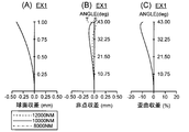
- FIG. 6 is an aberration diagram of Example 1.
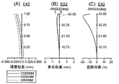
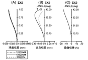
- FIG. 6 is an aberration diagram of Example 2.
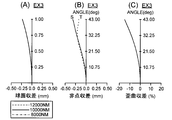
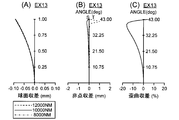
- FIG. 6 is an aberration diagram of Example 3.
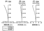
- FIG. 6 is an aberration diagram of Example 4.
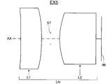
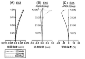
- FIG. 6 is an aberration diagram of Example 5.
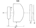
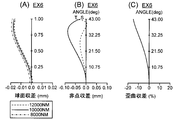
- FIG. 10 is an aberration diagram of Example 6.
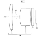
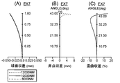
- FIG. 10 is an aberration diagram of Example 7.
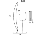
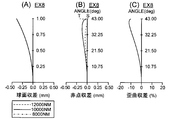
- FIG. 10 is an aberration diagram of Example 8.
- FIG. 10 is an aberration diagram of Example 9.
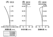
- FIG. 10 is an aberration diagram of Example 10.
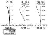
- FIG. 10 shows aberration diagrams of Example 11.
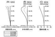
- FIG. 10 is an aberration diagram of Example 12.
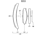
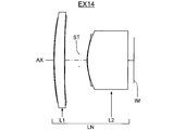
- Aberration diagram of Example 13 The lens block diagram of 14th Embodiment (Example 14).
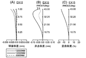
- FIG. 18 shows aberration diagrams of Example 15.
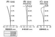
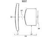
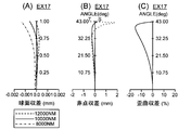
- Aberration diagram of Example 16 The lens block diagram of 17th Embodiment (Example 17).
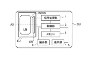
- the schematic diagram which shows the schematic structural example of the digital apparatus carrying a far-infrared lens system.
- the far-infrared lens system according to the present invention is a lens system used in the far-infrared band, and includes a first lens having a positive power and a second lens having a positive power in order from the object side.
- the refractive index of the lens material that is composed of a single lens and has the largest core thickness in each lens is greater than 2.0 and less than or equal to 3.9 at a wavelength of 10 ⁇ m, satisfying the following conditional expression (1), It is characterized by an angle of view larger than 30 °. 2.50 ⁇ f1 / f ⁇ 7.40 (1)
- f1 focal length of the first lens
- f focal length of the entire far-infrared lens system, It is.
- the positive power first and second lenses are a single lens element that functions as a single lens. Therefore, not only a single lens made of a uniform optical material but also a lens core surface made of a uniform optical material may be coated with a coating layer made of a thin layer of a material different from the lens core (for example, a resin material). .
- the lens having a coating layer include a composite lens such as a composite aspherical lens. If an attempt is made to make use of the characteristics of the material constituting the lens core (for example, silicon), it is necessary to reduce the thickness of the coating layer. However, a thin material that does not impair the optical characteristics of the main lens material may be optically bonded.
- the optically bonded material has a sufficient thickness in the far-infrared band, and any material can be used as long as the integral structure with the main lens material functions as a single lens.
- the two lenses of Example 1 and Examples 3 to 11 described later and the first lens of Example 2 are both single lenses, the second lens of Example 2, and the two lenses of Examples 12 to 17. This lens is a compound lens.
- the refractive index is the ratio of the light traveling speed in the substance to the vacuum, and is displayed for the d-line (587 nm) in the visible region.
- the refractive index for a wavelength of 10 ⁇ m is typically representative.
- the material constituting the lens core and the single lens is a lens material constituting the largest core thickness in each of the first and second lenses.
- the first and second lenses are characterized in that the refractive index of the lens core or single lens is greater than 2.0 and less than or equal to 3.9 at a wavelength of 10 ⁇ m. That is, a material having a refractive index greater than 2.0 and less than or equal to 3.9 at a wavelength of 10 ⁇ m among the far-infrared optical materials is used as a lens material that is the main of the first and second lenses.
- germanium (Ge) having a refractive index larger than 3.9 at a wavelength of 10 ⁇ m is well known, and is used in many infrared optical systems. Although it has a high refractive index, it is advantageous for aberration correction. However, since it is a rare mineral, the material cost is very high, which is an obstacle to the widespread use of far-infrared cameras. Further, as far-infrared lens materials having a refractive index smaller than 2.0, inorganic crystal materials such as sodium chloride (NaCl) and potassium bromide (KBr) are known. These are inexpensive materials, but their refractive index is too low, which is disadvantageous for aberration correction, and it is difficult to construct a photographic lens system with a small number of lenses.
- NaCl sodium chloride
- KBr potassium bromide
- silicon (Si, refractive index: 3.4178) is a representative material having a refractive index at a wavelength of 10 ⁇ m of more than 2.0 and 3.9 or less.
- silicon does not have the same refractive index as germanium, it has a relatively high refractive index among far-infrared lens materials, so it is sufficiently advantageous for aberration correction and constitutes an optical system with excellent performance with a small number of sheets. Is possible.
- a material having a refractive index larger than 2.0 at a wavelength of 10 ⁇ m all the curvatures of the lens can be relaxed.
- a lens system with a wide angle and a short focal length can reduce spherical aberration and It is possible to satisfactorily correct on-axis and off-axis aberrations such as field curvature. Further, by using a material having a refractive index of 3.9 or less at a wavelength of 10 ⁇ m, a lens system can be manufactured with an inexpensive material that does not contain germanium, which is a rare raw material.
- the first lens has a configuration in which the focal length f1 satisfies the conditional expression (1).
- This configuration has a longer focal length as compared with a conventional wide-angle lens system having two positive lenses.
- the focal length is shortened and the lens back is also shortened.
- Most non-cooled far infrared sensors do not require cooling, but in order to increase sensitivity, the front of the light receiving surface is sealed with a window material, and a vacuum is applied between the window material and the light receiving surface. ing. Since this structure is the same for a sensor having a small number of pixels and a small screen size, the lens system for a small sensor requires a larger lens back than the focal length.
- Far infrared rays are mainly infrared rays having a wavelength in the range of 7 to 14 ⁇ m.
- the body temperature of humans and animals is emitted light having a wavelength of 8 to 12 ⁇ m, and most of the far infrared optical system is used at a wavelength of 8 to 12 ⁇ m.
- the far-infrared region with a wavelength of 8 to 12 ⁇ m is the range in which the temperature of a substance can be detected, and there are many things that can be applied, such as temperature measurement, human detection in the dark, and security.
- far-infrared cameras are not widely used because lens materials that transmit far-infrared rays are materials containing expensive rare materials or materials that are difficult to process. This is because the lens system used is expensive.
- far-infrared sensor manufacturing technology has advanced, and inexpensive thermopiles, uncooled microbolometers, and the like have been manufactured, and an inexpensive lens system that is compatible with these is desired.
- the first lens and the second lens are formed in order from the object side, and the lens system has a small number of lenses, thereby reducing the processing cost of the lens system and reducing the cost. It is possible to provide a lens system.
- conditional expression (1a) it is desirable to satisfy the following conditional expression (1a), and it is more desirable to satisfy the conditional expression (1b). 2.50 ⁇ f1 / f ⁇ 6.76 (1a) 3.73 ⁇ f1 / f ⁇ 6.01 (1b)
- conditional expressions (1a) and (1b) define more preferable condition ranges based on the above viewpoints, etc., among the condition ranges defined by the conditional expression (1). Therefore, the above effect can be further enhanced by preferably satisfying conditional expression (1a), more preferably satisfying conditional expression (1b).
- the dispersion ⁇ at a wavelength of 8 to 12 ⁇ m is defined by the following formula (FD)
- FD dispersion ⁇ of the lens material constituting the largest core thickness in each of the first and second lenses
- ⁇ (N10-1) / (N8-N12) (FD)
- N10 refractive index at a wavelength of 10 ⁇ m
- N8 refractive index at a wavelength of 8 ⁇ m
- N12 refractive index at a wavelength of 12 ⁇ m
- the Abbe number ⁇ d of d-line is used for visible light.
- Nd the refractive index at the d line
- Nf the refractive index at the F line
- Nc the refractive index at the C line. Rate.
- the lens material having the largest core thickness of each lens has a value of dispersion ⁇ larger than 100.
- a far-infrared lens system that needs to perform color correction in a wide wavelength band such as a wavelength of 8 to 12 ⁇ m and, depending on the application, a wavelength of 7 to 14 ⁇ m, is quite advantageous in terms of chromatic aberration. Design becomes possible. Even for applications that require high-performance lenses, it is possible to obtain a lens system with sufficient performance with as few as two without performing special color correction using a diffraction grating, etc. Can be Further, since Si is cheaper than Ge, Si can be further reduced in cost.
- the dispersion ⁇ is made of a highly dispersed material smaller than 100, chromatic aberration correction may be insufficient. Even if a large number of aspheric surfaces are used and the aberration at a wavelength of 10 ⁇ m is kept small, the spot diameter becomes several to ten times the pixel pitch, and the far-infrared image that can be acquired becomes blurred, thereby obtaining sufficient resolution. It becomes difficult.
- the focal length range of the first lens is defined by the conditional expression (1) so that a sufficient lens back can be secured even for a far-infrared sensor having a small screen size at a low cost.
- conditional expression (2) that defines the focal length ratio between the first lens and the second lens, the aberration correction burden is appropriately shared by each lens even in a wide-angle lens system, and a lens system with good performance can be obtained. This can be realized with as few as two sheets.
- the distance between the first lens and the second lens is set to be a wide-angle lens system. It is difficult to obtain a sufficient space for placing a lens barrel part or a diaphragm between the first lens and the second lens, making it difficult to construct a lens system. Further, since the light flux passes through the same height between the first lens and the second lens, it is difficult to sufficiently correct the curvature of field when the axial performance such as spherical aberration is ensured.
- conditional expression (2) if the lower limit of conditional expression (2) is exceeded and the focal length of the second lens becomes smaller than the focal length of the first lens, the total length of the lens system increases and the second lens is an axial light beam. A large spherical aberration is generated, and the off-axis light beam is strongly refracted inward to generate coma aberration, making it difficult to obtain good optical performance.
- conditional expression (2a) It is desirable to satisfy the following conditional expression (2a), and it is more desirable to satisfy conditional expression (2b). 0.12 ⁇ f2 / f1 ⁇ 0.40 (2a) 0.12 ⁇ f2 / f1 ⁇ 0.25 (2b)
- conditional expressions (2a) and (2b) define more preferable condition ranges based on the above viewpoints, etc., among the condition ranges defined by the conditional expression (2). Therefore, the above effect can be further enhanced by preferably satisfying conditional expression (2a), more preferably satisfying conditional expression (2b).
- Conditional expression (3) (R1 + R2) / (R1-R2) is called a “shaping factor” indicating the shape of one lens.
- the sign plus or minus differs depending on the direction of the lens surface, but if the curvature radii on both sides are close to each other, including the sign, the lens will have a strong meniscus and the absolute value of the shaping factor will be large.
- the curvature radius R1 has a positive value convex toward the object side, and the first lens has a positive power. Therefore, the larger the negative value, the stronger the meniscus degree.
- the first lens has spherical aberration and curvature of field. Such correction is mainly performed, and the aberration due to the positive power generated in the second lens can be offset, thereby improving the performance.
- the shaping factor increases beyond the upper limit of conditional expression (3), the meniscus degree of the positive lens becomes extremely weak, and off-axis rays are refracted greatly before and after the first lens, resulting in coma aberration on the outside. It tends to deteriorate the performance.
- the shaping factor decreases beyond the lower limit of conditional expression (3), the meniscus degree of the positive lens increases, and off-axis rays pass through a higher position on the object side surface of the first lens. It tends to increase and degrade performance.
- D1 Total core thickness on the axis from the most object side surface to the most image side surface of the first lens
- f focal length of the entire far-infrared lens system
- the thickness of the first lens on which the off-axis light beam is incident at a large angle greatly affects the performance. Therefore, in the far-infrared lens system according to the present invention, the first standard normalized by the focal length of the entire system. It is preferable to set the total core thickness of the lens within a predetermined range, and the conditional expression (4) defines the range. If the core thickness of the first lens is reduced beyond the lower limit of the conditional expression (4), the off-axis light beam has the same height on the most object side surface and the most image side surface of the first lens and has a similar curvature.
- the curvature of field generated by the first lens reaches the second lens without being sufficiently corrected, and finally the aberration cannot be sufficiently satisfactorily corrected. It becomes difficult to obtain good performance.
- the distance from the object side surface to the stop increases the most, and the off-axis light beam passes through the high position of the first lens. Coma aberration is generated, and it is difficult to obtain a lens system with good performance with a small number of lenses of two.
- LB a length obtained by converting the distance from the most image side surface of the second lens to the image surface in terms of air
- f focal length of the entire far-infrared lens system
- the lens back becomes smaller than the lower limit of conditional expression (5), it will be difficult to secure a space for inserting a cover glass or the like located in front of the sensor light receiving surface even if the number of optical members is reduced as much as possible. Becomes difficult. At this time, the periphery of the light receiving surface of the sensor cannot be sealed in a vacuum, and the heat of the sensor itself rides on the image as noise, and there is a possibility that a clear image cannot be obtained.
- the lens back increases beyond the upper limit of conditional expression (5), the total lens length increases, and the off-axis luminous flux passes through the high position of the lens and accordingly corrects off-axis coma and curvature of field. It becomes difficult to do. As a result, it is difficult to construct a good lens system with as few as two.
- the far-infrared lens system according to the present invention is suitable as an imaging lens system for a far-infrared camera system.
- a far-infrared camera system As described above, one of the reasons why far-infrared cameras are not widespread is that lens materials and lens processing are expensive.
- a diffraction grating may be provided on at least one of the lens surfaces of the first and second lenses.
- a diffraction grating By providing a diffraction grating, it is possible to satisfactorily correct axial chromatic aberration and the like.
- a cross-sectional shape of the diffraction grating a step shape or a kinoform may be used in addition to the binary shape.
- the cover glass attached to the far-infrared sensor is made of silicon, but germanium may be used.
- the same material as the cover glass may be used for the second lens, a different material from the cover glass, and
- the image surface side of the second lens may be a flat surface and may be disposed close to the cover glass.
- far-infrared lens systems or imaging optical devices for digital devices such as night vision devices, thermography, portable terminals, camera systems (for example, digital cameras, surveillance cameras, security cameras, in-vehicle cameras) makes high performance for digital devices.
- a far-infrared image input function with high performance can be added at a low cost and in a compact manner, contributing to the compactness, high performance, high functionality, and the like.
- lens materials and lens processing are expensive. Therefore, a simple two-lens lens system is used as the far-infrared lens system. Accordingly, it is possible to realize a low-cost camera system that can reduce the processing cost of the lens.
- the far-infrared lens system according to the present invention is suitable for use as an imaging optical system for a digital device with a far-infrared image input function (for example, a portable terminal, a drive recorder, etc.). By combining them, it is possible to configure a far-infrared imaging optical device that optically captures a far-infrared image of a subject and outputs it as an electrical signal.
- the imaging optical device is an optical device that constitutes a main component of a camera used for still image shooting or moving image shooting of a subject. For example, a far-infrared ray that forms a far-infrared optical image of an object in order from the object (that is, subject) side.
- It comprises a lens system and a far infrared sensor (imaging device) that converts a far infrared optical image formed by the far infrared lens system into an electrical signal.
- the far-infrared lens system having the above-described characteristic configuration is arranged so that the far-infrared optical image of the subject is formed on the light-receiving surface (that is, the imaging surface) of the far-infrared sensor. Therefore, it is possible to realize an imaging optical device having high performance and a digital device including the same.
- Examples of digital devices with a far-infrared image input function include camera systems such as infrared cameras, surveillance cameras, security cameras, in-vehicle cameras, aircraft cameras, digital cameras, video cameras, videophone cameras, and personal computers. , Night vision devices, thermography, portable digital devices (for example, small and portable information device terminals such as mobile phones, smart phones (high-function mobile phones), tablet terminals, mobile computers, etc.), and peripheral devices (scanners, printers) , Mouse, etc.), other digital devices (drive recorders, defense devices, etc.), etc., which have a camera function built in or externally mounted.
- camera systems such as infrared cameras, surveillance cameras, security cameras, in-vehicle cameras, aircraft cameras, digital cameras, video cameras, videophone cameras, and personal computers.
- Night vision devices thermography
- portable digital devices for example, small and portable information device terminals such as mobile phones, smart phones (high-function mobile phones), tablet terminals, mobile computers, etc.
- peripheral devices scanners, printers
- an infrared camera system by using an imaging optical device for far infrared rays, but also to provide an infrared camera function and a night vision function by installing the imaging optical device in various devices.
- a temperature measurement function can be added.
- a digital device having a far-infrared image input function such as a smartphone with an infrared camera can be configured.
- FIG. 35 shows a schematic configuration example of the digital device DU in a schematic cross section.
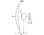
- the imaging optical device LU mounted on the digital device DU shown in FIG. 35 is a far-infrared lens system LN (AX: light) that forms a far-infrared optical image (image plane) IM of an object in order from the object (that is, subject) side.
- Axis and a far infrared sensor (imaging device) SR that converts an optical image IM formed on the light receiving surface (imaging surface) SS by the far infrared lens system LN into an electrical signal.
- the imaging optical device LU On the image plane IM side of the far-infrared lens system LN, the cover glass of the far-infrared sensor SR, an optical filter arranged as necessary, and the like are positioned as parallel plates (not shown).
- the imaging optical device LU When a digital device DU with an image input function is constituted by this imaging optical device LU, the imaging optical device LU is usually arranged inside the body, but when necessary to realize the camera function, a form as necessary is adopted. Is possible.
- the unitized imaging optical device LU can be configured to be detachable or rotatable with respect to the main body of the digital device DU.
- the far-infrared lens system LN is a two-lens single-focus lens composed of two lenses of a first lens and a second lens in order from the object side.
- the light-receiving surface of the far-infrared sensor SR As described above, the light-receiving surface of the far-infrared sensor SR.
- An optical image IM composed of far infrared rays is formed on the SS.
- the far-infrared sensor SR for example, a far-infrared image sensor (thermosensor or the like) having a plurality of pixels (for example, several thousand to several hundred thousand pixels) and using a wavelength of about 8 to 12 ⁇ m is used.
- the far-infrared lens system LN is provided so that the optical image IM of the subject is formed on the light receiving surface SS which is a photoelectric conversion unit of the far-infrared sensor SR, the optical image formed by the far-infrared lens system LN. IM is converted into an electrical signal by the far-infrared sensor SR.
- the far infrared sensor SR include a pyroelectric sensor, a microbolometer, and a thermopile.
- the pyroelectric sensor uses a pyroelectric effect in which ceramic containing lead zirconate titanate or the like spontaneously polarizes due to a change in temperature. In most cases, the pyroelectric sensor has a single light receiving surface and is an inexpensive temperature sensor.
- the microbolometer is a temperature sensor that has a light receiving surface in which heat sensitive materials such as amorphous silicon and vanadium oxide are two-dimensionally arranged by a microfabrication technique and detects a change in resistance value due to a temperature rise.
- thermopile is a temperature sensor that uses thermocouples capable of converting heat into electric energy in series or in parallel to form a sensor surface, and is the second cheapest sensor after a pyroelectric sensor.
- the digital device DU includes a signal processing unit 1, a control unit 2, a memory 3, an operation unit 4, a display unit 5 and the like in addition to the imaging optical device LU.
- the signal generated by the far-infrared sensor SR is subjected to predetermined digital image processing, image compression processing, and the like as required by the signal processing unit 1 and recorded as a digital video signal in the memory 3 (semiconductor memory, optical disk, etc.).
- the signal is transmitted to another device via a cable or converted into an infrared signal or the like (for example, a communication function of a mobile phone).
- the control unit 2 is composed of a microcomputer, and performs control of functions such as a photographing function (still image photographing function, moving image photographing function, etc.), an image reproduction function, and the like; and a lens moving mechanism for focusing.
- the control unit 2 controls the imaging optical device LU so as to perform at least one of still image shooting and moving image shooting of a subject.
- the display unit 5 includes a display such as a liquid crystal monitor, and performs image display using an image signal converted by the far infrared sensor SR or image information recorded in the memory 3.
- the operation unit 4 is a part including operation members such as an operation button (for example, a release button) and an operation dial (for example, a shooting mode dial), and transmits information input by the operator to the control unit 2.
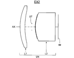
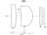
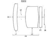
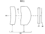
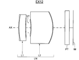
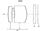
- FIGS. 1, 3,..., 31 and 33 show first to seventeenth embodiments of the far-infrared lens system LN in an infinitely focused state in optical cross sections.
- the far-infrared lens system LN of the first to seventeenth embodiments includes, in order from the object side, a first lens L1 having a positive power and a second lens L2 having a positive power.
- the first lens L1 and the second lens L2 are both single lenses.
- the first lens L1 is a single lens
- the second lens L2 is a compound lens.
- both the first lens L1 and the second lens L2 are compound lenses.
- the compound lens has a structure in which the entire lens core (up to the edge of the lens) made of an inorganic material is covered with a coating layer made of a relatively thin resin material, but the effective area (effective diameter from the optical axis AX). Since the coating layer other than the range up to the position does not affect the optical performance, the coating layer other than the effective region is not shown in each lens configuration diagram.
- the far-infrared lens system LN corresponds to the protective cover glass of the far-infrared sensor SR on the image plane IM side.
- a parallel plate PT is arranged.
- the second lens L2 and the protective cover glass of the far-infrared sensor SR are integrated.
- Examples 1 to 17 (EX1 to 17) listed here are numerical examples corresponding to the first to seventeenth embodiments, respectively, and are lens configuration diagrams showing the first to seventeenth embodiments. (FIG. 1, FIG. 3,..., FIG. 33) show optical configurations such as the lens cross-sectional shape and lens arrangement of the corresponding Examples 1 to 17, respectively.
- the surface with * in the surface number i is an aspheric surface, and the surface shape is defined by the following formula (AS) using a local orthogonal coordinate system (x, y, z) with the surface vertex as the origin.
- z (c ⁇ h 2 ) / [1 + ⁇ ⁇ 1 ⁇ (1 + K) ⁇ c 2 ⁇ h 2 ⁇ ] + ⁇ (Aj ⁇ h j ) (AS)
- z the amount of sag in the direction of the optical axis AX at the position of the height h (based on the surface vertex)
- c curvature at the surface vertex (reciprocal of paraxial radius of curvature r)
- K conic constant
- Aj j-order aspheric coefficient ( ⁇ represents the sum of the fourth to ⁇ orders for j), It is.
- the refractive index and dispersion data of the optical material constituting each lens are as follows: Show.
- the parallel plate PT in front of the image plane IM is a silicon protective plate (cover glass) of the far-infrared sensor SR.
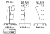
- the spherical aberration diagram (A) shows the amount of spherical aberration at a design wavelength (evaluation wavelength) of 10000 nm indicated by a solid line, the amount of spherical aberration at a wavelength of 8000 nm indicated by a dashed line, and the amount of spherical aberration at a wavelength of 12000 nm indicated by a broken line.
- the vertical axis represents a value obtained by normalizing the incident height to the pupil by the maximum height (that is, the relative pupil height).
- the broken line T is the tangential image plane at the design wavelength of 10000 nm
- the solid line S is the sagittal image plane at the design wavelength of 10000 nm
- the vertical axis represents the half angle of view ⁇ (ANGLE, °).
- the horizontal axis represents the distortion (%) at the design wavelength of 10000 nm
- the vertical axis represents the half angle of view ⁇ (ANGLE, °).
- the maximum value of the half field angle ⁇ corresponds to the maximum image height Y ′ (half the diagonal length of the light receiving surface SS of the far-infrared sensor SR) on the image plane IM.
- the far-infrared lens system LN (FIG. 1) of Example 1 (EX1) is configured by a positive power first lens L1, an aperture stop ST, and a positive power second lens L2 in order from the object side. Yes.
- the first lens L1 is a positive meniscus lens convex on the object side
- the second lens L2 is a positive meniscus lens convex on the image side.
- the parallel flat plates PT constituting the sixth surface and the seventh surface are protective cover glasses attached to the far-infrared sensor SR.
- the far-infrared lens system LN (FIG. 3) of Example 2 (EX2) includes, in order from the object side, a first lens L1 having a positive power, an aperture stop ST, and a second lens having a positive power having a coating layer on the object side. L2.
- the first lens L1 is a positive meniscus lens convex toward the object side
- the second lens L2 is a positive meniscus lens convex toward the object side.
- the most object side surface of the second lens L2 is an aspherical surface.
- a cover glass for the far-infrared sensor SR is integrated with the second lens L2 constituting the fourth surface to the sixth surface.
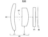
- the far-infrared lens system LN (FIG. 5) of Example 3 (EX3) is configured by a positive power first lens L1, an aperture stop ST, and a positive power second lens L2 in order from the object side. Yes.
- the first lens L1 is a positive meniscus lens convex on the object side
- the second lens L2 is a positive meniscus lens convex on the image side.
- the parallel flat plates PT constituting the sixth surface and the seventh surface are protective cover glasses attached to the far-infrared sensor SR.
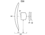
- the far-infrared lens system LN (FIG. 7) of Example 4 is configured by a positive power first lens L1, an aperture stop ST, and a positive power second lens L2 in order from the object side. Yes.
- the first lens L1 is a positive meniscus lens convex on the object side
- the second lens L2 is a positive meniscus lens convex on the image side.
- the parallel flat plates PT constituting the sixth surface and the seventh surface are protective cover glasses attached to the far-infrared sensor SR.
- the far-infrared lens system LN (FIG. 9) of Example 5 is configured by a positive power first lens L1, an aperture stop ST, and a positive power second lens L2 in order from the object side. Yes.
- the first lens L1 is a biconvex positive lens
- the second lens L2 is a positive plano-convex lens with a convex surface facing the object side. Both surfaces of the first lens L1 and the object side surface of the second lens L2 are aspheric.
- a cover glass for the far-infrared sensor SR is integrated with the second lens L2 constituting the fourth surface and the fifth surface.
- the far-infrared lens system LN (FIG. 11) of Example 6 (EX6) includes, in order from the object side, a first lens L1 having a positive power, an aperture stop ST, and a second lens L2 having a positive power. Yes.
- the first lens L1 is a positive meniscus lens convex on the object side
- the second lens L2 is a positive meniscus lens convex on the image side. Both surfaces of the first lens L1 and both surfaces of the second lens L2 are aspheric.
- the parallel flat plates PT constituting the sixth surface and the seventh surface are protective cover glasses attached to the far-infrared sensor SR.
- the far-infrared lens system LN (FIG. 13) of Example 7 (EX7) is composed of, in order from the object side, a positive lens first lens L1, an aperture stop ST, and a positive power second lens L2. Yes.
- the first lens L1 is a positive meniscus lens convex toward the object side
- the second lens L2 is a biconvex positive lens. Both surfaces of the first lens L1 and both surfaces of the second lens L2 are aspheric.
- the parallel flat plates PT constituting the sixth surface and the seventh surface are protective cover glasses attached to the far-infrared sensor SR.
- the far-infrared lens system LN (FIG. 15) of Example 8 (EX8) includes, in order from the object side, a first lens L1 having a positive power, an aperture stop ST, and a second lens L2 having a positive power. Yes.
- the first lens L1 is a positive meniscus lens convex on the object side
- the second lens L2 is a positive meniscus lens convex on the image side.
- the parallel flat plates PT constituting the sixth surface and the seventh surface are protective cover glasses attached to the far-infrared sensor SR.
- the far-infrared lens system LN (FIG. 17) of Example 9 (EX9) includes, in order from the object side, a first lens L1 having a positive power, an aperture stop ST, and a second lens L2 having a positive power. Yes.
- the first lens L1 is a biconvex positive lens
- the second lens L2 is a positive meniscus lens convex to the image side. Both surfaces of the first lens L1 and both surfaces of the second lens L2 are aspheric.
- the parallel flat plates PT constituting the sixth surface and the seventh surface are protective cover glasses attached to the far-infrared sensor SR.
- the far-infrared lens system LN (FIG. 19) of Example 10 (EX10) includes, in order from the object side, a first lens L1 having a positive power, an aperture stop ST, and a second lens L2 having a positive power. Yes.
- the first lens L1 is a positive meniscus lens convex toward the object side
- the second lens L2 is a biconvex positive lens. Both surfaces of the first lens L1 and both surfaces of the second lens L2 are aspheric.
- the parallel flat plates PT constituting the sixth surface and the seventh surface are protective cover glasses attached to the far-infrared sensor SR.
- the far-infrared lens system LN (FIG. 21) of Example 11 (EX11) includes, in order from the object side, a first lens L1 having a positive power, an aperture stop ST, and a second lens L2 having a positive power. Yes.
- the first lens L1 is a positive meniscus lens convex on the image side
- the second lens L2 is a positive meniscus lens convex on the image side. Both surfaces of the first lens L1 and both surfaces of the second lens L2 are aspheric.
- the parallel flat plates PT constituting the sixth surface and the seventh surface are protective cover glasses attached to the far-infrared sensor SR.
- the far-infrared lens system LN (FIG. 23) of Example 12 is a positive power first lens L1 having a coating layer on both surfaces, an aperture stop ST, and a positive lens having a coating layer on both surfaces in order from the object side.
- a second lens L2 for power When each lens is viewed with a paraxial surface shape, the first lens L1 is a positive meniscus lens convex on the object side, and the second lens L2 is a positive meniscus lens convex on the image side. Both surfaces of the first lens L1 and both surfaces of the second lens L2 are aspheric.
- the parallel flat plates PT constituting the tenth surface and the eleventh surface are protective cover glasses attached to the far-infrared sensor SR.
- a positive-power first lens L1 having a coating layer on both surfaces in order from the object side, a positive-power first lens L1 having a coating layer on both surfaces, an aperture stop ST, and a positive lens having a coating layer on both surfaces.
- a second lens L2 for power when each lens is viewed with a paraxial surface shape, the first lens L1 is a positive meniscus lens convex toward the object side, and the second lens L2 is a biconvex positive lens. Both surfaces of the first lens L1 and both surfaces of the second lens L2 are aspheric.
- the parallel flat plates PT constituting the tenth surface and the eleventh surface are protective cover glasses attached to the far-infrared sensor SR.
- the far-infrared lens system LN (FIG. 27) of Example 14 has, in order from the object side, a positive-power first lens L1 having a coating layer on both surfaces, an aperture stop ST, and a coating layer on the object side surface. And a positive power second lens L2.
- the first lens L1 is a biconvex positive lens
- the second lens L2 is a positive meniscus lens convex toward the object side. Both surfaces of the first lens L1 and the object side surface of the second lens L2 are aspheric.
- a cover glass for the far-infrared sensor SR is integrated with the second lens L2 constituting the sixth surface to the eighth surface.
- the far-infrared lens system LN (FIG. 29) of Example 15 (EX15) includes, in order from the object side, a first lens L1 having a positive power having a coating layer on both surfaces, an aperture stop ST, and a positive lens having a coating layer on both surfaces.
- a second lens L2 for power When each lens is viewed with a paraxial surface shape, the first lens L1 is a positive meniscus lens convex on the object side, and the second lens L2 is a positive meniscus lens convex on the image side. Both surfaces of the first lens L1 and both surfaces of the second lens L2 are aspheric.
- the parallel flat plates PT constituting the tenth and eleventh surfaces are protective cover glasses attached to the far infrared sensor SR.
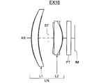
- the far-infrared lens system LN (FIG. 31) of Example 16 (EX16) is, in order from the object side, a positive-power first lens L1 having a coating layer on both surfaces, an aperture stop ST, and a positive lens having a coating layer on both surfaces.
- a second lens L2 for power When each lens is viewed with a paraxial surface shape, the first lens L1 is a positive meniscus lens convex toward the object side, and the second lens L2 is a biconvex positive lens. Both surfaces of the first lens L1 and both surfaces of the second lens L2 are aspheric.
- the parallel flat plates PT constituting the tenth surface and the eleventh surface are protective cover glasses attached to the far-infrared sensor SR.
- the far-infrared lens system LN (FIG. 33) of Example 17 (EX17) has, in order from the object side, a positive-power first lens L1 having a coating layer on both surfaces, an aperture stop ST, and a coating layer on the object side surface. And a positive power second lens L2.
- the first lens L1 is a biconvex positive lens
- the second lens L2 is a positive plano-convex lens with a convex surface facing the object side. Both surfaces of the first lens L1 and the object side surface of the second lens L2 are aspheric.
- a cover glass for the far-infrared sensor SR is integrated with the second lens L2 constituting the sixth surface to the eighth surface.
- Example 1 Unit mm Surface data i r d N10 ⁇ OB INFINITY INFINITY 1 27.49962 2.389440 3.4178 1860 2 41.17168 3.929118 3 (ST) INFINITY 0.178644 4 -14.13077 5.000000 3.4178 1860 5 -6.66742 2.500000 6 INFINITY 1.000000 3.4178 1860 7 INFINITY 0.900000 IM INFINITY 0.000000
- Example 2 Unit mm Surface data i r d N10 ⁇ OB INFINITY INFINITY 1 15.19286 1.500000 3.4178 1860 2 21.45350 2.112804 3 (ST) INFINITY 1.000000 4 * 7.47915 0.100000 1.5226 15.10 5 10.15462 6.000000 3.4178 1860 6 1.0E15 0.900000 IM INFINITY 0.000000
- Example 3 Unit mm Surface data i r d N10 ⁇ OB INFINITY INFINITY 1 13.11422 1.500000 3.4178 1860 2 16.49414 2.006408 3 (ST) INFINITY 1.043581 4 -72.07863 2.590280 3.4178 1860 5 -8.85877 1.795882 6 INFINITY 1.000000 3.4178 1860 7 INFINITY 0.900000 IM INFINITY 0.000000
- Example 4 Unit mm Surface data i r d N10 ⁇ OB INFINITY INFINITY 1 25.38763 2.176300 3.4178 1860 2 38.15760 3.547059 3 (ST) INFINITY 0.188329 4 -14.22854 5.000000 3.4178 1860 5 -6.73748 2.500000 6 INFINITY 1.000000 3.4178 1860 7 INFINITY 0.900000 IM INFINITY 0.000000
- Example 5 Unit mm Surface data i r d N10 ⁇ OB INFINITY INFINITY 1 * 77.48277 3.457975 3.4178 1860 2 * -38.26964 1.500000 3 (ST) INFINITY 1.490901 4 * 10.20600 6.000000 3.4178 1860 5 INFINITY 0.900000 IM INFINITY 0.000000
- Example 6 Unit mm Surface data i r d N10 ⁇ OB INFINITY INFINITY 1 * 23.79133 1.500000 3.4178 1860 2 * 140.25331 0.632176 3 (ST) INFINITY 1.129165 4 * -8.95626 4.918622 3.4178 1860 5 * -6.59171 3.047744 6 INFINITY 1.000000 3.4178 1860 7 INFINITY 0.900000 IM INFINITY 0.000000
- Example 7 Unit mm Surface data i r d N10 ⁇ OB INFINITY INFINITY 1 * 28.12955 1.500000 3.4178 1860 2 * 60.79737 2.038139 3 (ST) INFINITY 1.421250 4 * 13.13338 5.000000 3.4178 1860 5 * -10.29980 0.389890 6 INFINITY 1.000000 3.4178 1860 7 INFINITY 0.900000 IM INFINITY 0.000000
- Example 8 Unit mm Surface data i r d N10 ⁇ OB INFINITY INFINITY 1 22.65998 2.006645 3.4178 1860 2 33.99470 3.086700 3 (ST) INFINITY 0.187460 4 -14.06617 5.000000 3.4178 1860 5 -6.78391 2.500000 6 INFINITY 1.000000 3.4178 1860 7 INFINITY 0.900000 IM INFINITY 0.000000
- Example 9 Unit mm Surface data i r d N10 ⁇ OB INFINITY INFINITY 1 * 43.76343 2.221565 3.4178 1860 2 * -206.24886 1.472347 3 (ST) INFINITY 0.901371 4 * -8.38086 5.000000 3.4178 1860 5 * -6.35757 3.263241 6 INFINITY 1.000000 3.4178 1860 7 INFINITY 0.900000 IM INFINITY 0.000000
- Example 10 Unit mm Surface data i r d N10 ⁇ OB INFINITY INFINITY 1 * 24.39058 1.500000 3.4178 1860 2 * 50.47864 1.708722 3 (ST) INFINITY 1.463890 4 * 11.95186 5.000000 3.4178 1860 5 * -11.29497 0.271594 6 INFINITY 1.000000 3.4178 1860 7 INFINITY 0.900000 IM INFINITY 0.000000
- Example 11 Unit mm Surface data i r d N10 ⁇ OB INFINITY INFINITY 1 * -33.26351 2.607340 3.4178 1860 2 * -18.95000 1.552262 3 (ST) INFINITY 1.350176 4 * -9.20889 5.000000 3.4178 1860 5 * -6.76124 3.590222 6 INFINITY 1.000000 3.4178 1860 7 INFINITY 0.900000 IM INFINITY 0.000000
- Example 12 Unit mm Surface data i r d N10 ⁇ OB INFINITY INFINITY 1 * 14.22191 0.100000 1.5226 15.10 2 14.12191 1.500000 3.4178 1860 3 26.10156 0.100000 1.5226 15.10 4 * 26.00156 0.545922 5 (ST) INFINITY 0.587787 6 * -11.63910 0.100000 1.5226 15.10 7 -11.73910 5.000000 3.4178 1860 8 -7.14015 0.100000 1.5226 15.10 9 * -7.24015 2.754097 10 INFINITY 1.000000 3.4178 1860 11 INFINITY 0.900000 IM INFINITY 0.000000
- Example 13 Unit mm Surface data i r d N10 ⁇ OB INFINITY INFINITY 1 * 13.15744 0.100000 1.5226 15.10 2 13.05744 1.651328 3.4178 1860 3 17.47125 0.100000 1.5226 15.10 4 * 17.37125 2.332330 5 (ST) INFINITY 1.162452 6 * 24.77130 0.100000 1.5226 15.10 7 24.67130 2.162416 3.4178 1860 8 -9.25400 0.100000 1.5226 15.10 9 * -9.35400 0.819559 10 INFINITY 1.000000 3.4178 1860 11 INFINITY 0.900000 IM INFINITY 0.000000
- Example 14 Unit mm Surface data i r d N10 ⁇ OB INFINITY INFINITY 1 * 39.60693 0.100000 1.5226 15.10 2 37.84099 1.500000 3.4178 1860 3 132.96439 0.100000 1.5226 15.10 4 * -74.31562 2.114237 5 (ST) INFINITY 1.123688 6 * 6.43904 0.100000 1.5226 15.10 7 9.49876 6.000000 3.4178 1860 8 1.0E15 0.900000 IM INFINITY 0.000000
- Example 15 Unit mm Surface data i r d N10 ⁇ OB INFINITY INFINITY 1 * 13.34570 0.100000 1.6700 22.33 2 13.24570 1.500000 3.4178 1860 3 24.67262 0.100000 1.6700 22.33 4 * 24.57262 0.584695 5 (ST) INFINITY 0.459801 6 * -11.71626 0.100000 1.5226 15.10 7 -11.81626 5.000000 3.4178 1860 8 -7.20363 0.100000 1.5226 15.10 9 * -7.30363 2.675682 10 INFINITY 1.000000 3.4178 1860 11 INFINITY 0.900000 IM INFINITY 0.000000
- Example 16 Unit mm Surface data i r d N10 ⁇ OB INFINITY INFINITY 1 * 13.15744 0.100000 1.5226 15.10 2 13.05744 1.530806 3.4178 1860 3 16.39283 0.100000 1.5226 15.10 4 * 16.29283 2.322649 5 (ST) INFINITY 1.216746 6 * 178.79265 0.100000 1.6700 22.33 7 178.69265 1.944737 3.4178 1860 8 -6.64235 0.100000 1.6700 22.33 9 * -6.74235 0.917302 10 INFINITY 1.000000 3.4178 1860 11 INFINITY 0.900000 IM INFINITY 0.000000
- Example 17 Unit mm Surface data i r d N10 ⁇ OB INFINITY INFINITY 1 * 34.89934 0.100000 1.5226 15.10 2 33.69657 1.500000 3.4178 1860 3 82.42368 0.100000 1.5226 15.10 4 * -120.08738 2.114237 5 (ST) INFINITY 1.123688 6 * 6.98192 0.100000 1.6700 22.33 7 9.23780 6.000000 3.4178 1860 8 INFINITY 0.900000 IM INFINITY 0.000000
Abstract
Description
物体側から順に、正のパワーを持つ第1レンズと、正のパワーを持つ第2レンズと、の2枚のレンズで構成され、各レンズにおいて最も大きい芯厚を構成するレンズ材料の屈折率が波長10μmで2.0より大きく3.9以下であり、以下の条件式(1)を満足し、半画角が30°よりも大きいことを特徴とする。
2.50<f1/f<7.40 …(1)
ただし、
f1:第1レンズの焦点距離、
f:遠赤外線レンズ系全体の焦点距離、
である。 To achieve the above object, the far-infrared lens system of the first invention is a lens system used in the far-infrared band,
In order from the object side, the first lens having positive power and the second lens having positive power are composed of two lenses, and the refractive index of the lens material constituting the largest core thickness in each lens is It is greater than 2.0 and less than or equal to 3.9 at a wavelength of 10 μm, satisfies the following conditional expression (1), and has a half angle of view greater than 30 °.
2.50 <f1 / f <7.40 (1)
However,
f1: focal length of the first lens,
f: focal length of the entire far-infrared lens system,
It is.
ν=(N10-1)/(N8-N12) …(FD)
ただし、
N10:波長10μmでの屈折率、
N8:波長8μmでの屈折率、
N12:波長12μmでの屈折率、
である。 The far-infrared lens system of the second invention is the above-described first invention, wherein the dispersion ν at a wavelength of 8 to 12 μm is defined by the following formula (FD), and the largest core in each of the first and second lenses: The dispersion ν of the lens material constituting the thickness is greater than 100.
ν = (N10-1) / (N8-N12) (FD)
However,
N10: refractive index at a wavelength of 10 μm,
N8: refractive index at a wavelength of 8 μm,
N12: refractive index at a wavelength of 12 μm,
It is.
0.11<f2/f1<0.60 …(2)
ただし、
f1:第1レンズの焦点距離、
f2:第2レンズの焦点距離、
である。 A far-infrared lens system according to a third aspect of the invention is characterized in that, in the first or second aspect of the invention, the following conditional expression (2) is satisfied.
0.11 <f2 / f1 <0.60 (2)
However,
f1: focal length of the first lens,
f2: focal length of the second lens,
It is.
-9.40<(R1+R2)/(R1-R2)<3.65 …(3)
ただし、
R1:第1レンズの最も物体側面の曲率半径、
R2:第1レンズの最も像側面の曲率半径、
である。 A far-infrared lens system of a fourth invention is characterized in that, in any one of the first to third inventions, the following conditional expression (3) is satisfied.
-9.40 <(R1 + R2) / (R1-R2) <3.65 (3)
However,
R1: radius of curvature of the most object side surface of the first lens,
R2: radius of curvature of the image side of the first lens,
It is.
0.34<D1/f<0.89 …(4)
ただし、
D1:第1レンズの最も物体側面から最も像側面までの軸上の合計芯厚、
f:遠赤外線レンズ系全体の焦点距離、
である。 A far-infrared lens system according to a fifth invention is characterized in that, in any one of the first to fourth inventions, the following conditional expression (4) is satisfied.
0.34 <D1 / f <0.89 (4)
However,
D1: Total core thickness on the axis from the most object side surface to the most image side surface of the first lens;
f: focal length of the entire far infrared lens system,
It is.
0.2<LB/f<1.1 …(5)
ただし、
LB:第2レンズの最も像側面から像面までの距離を空気換算した長さ、
f:遠赤外線レンズ系全体の焦点距離、
である。 A far-infrared lens system according to a sixth invention is characterized in that, in any one of the first to fifth inventions, the following conditional expression (5) is satisfied.
0.2 <LB / f <1.1 (5)
However,
LB: a length obtained by converting the distance from the most image side surface of the second lens to the image surface in terms of air,
f: focal length of the entire far-infrared lens system,
It is.
2.50<f1/f<7.40 …(1)
ただし、
f1:第1レンズの焦点距離、
f:遠赤外線レンズ系全体の焦点距離、
である。 Hereinafter, the far-infrared lens system, the imaging optical device, the digital device, and the like according to the present invention will be described. The far-infrared lens system according to the present invention is a lens system used in the far-infrared band, and includes a first lens having a positive power and a second lens having a positive power in order from the object side. The refractive index of the lens material that is composed of a single lens and has the largest core thickness in each lens is greater than 2.0 and less than or equal to 3.9 at a wavelength of 10 μm, satisfying the following conditional expression (1), It is characterized by an angle of view larger than 30 °.
2.50 <f1 / f <7.40 (1)
However,
f1: focal length of the first lens,
f: focal length of the entire far-infrared lens system,
It is.
2.50<f1/f<6.76 …(1a)
3.73<f1/f<6.01 …(1b)
これらの条件式(1a),(1b)は、前記条件式(1)が規定している条件範囲のなかでも、前記観点等に基づいた更に好ましい条件範囲を規定している。したがって、好ましくは条件式(1a)、更に好ましくは条件式(1b)を満たすことにより、上記効果をより一層大きくすることができる。 Regarding the focal length of the first lens, it is desirable to satisfy the following conditional expression (1a), and it is more desirable to satisfy the conditional expression (1b).
2.50 <f1 / f <6.76 (1a)
3.73 <f1 / f <6.01 (1b)
These conditional expressions (1a) and (1b) define more preferable condition ranges based on the above viewpoints, etc., among the condition ranges defined by the conditional expression (1). Therefore, the above effect can be further enhanced by preferably satisfying conditional expression (1a), more preferably satisfying conditional expression (1b).
ν=(N10-1)/(N8-N12) …(FD)
ただし、
N10:波長10μmでの屈折率、
N8:波長8μmでの屈折率、
N12:波長12μmでの屈折率、
である。 When the dispersion ν at a wavelength of 8 to 12 μm is defined by the following formula (FD), it is desirable that the dispersion ν of the lens material constituting the largest core thickness in each of the first and second lenses is larger than 100.
ν = (N10-1) / (N8-N12) (FD)
However,
N10: refractive index at a wavelength of 10 μm,
N8: refractive index at a wavelength of 8 μm,
N12: refractive index at a wavelength of 12 μm,
It is.
0.11<f2/f1<0.60 …(2)
ただし、
f1:第1レンズの焦点距離、
f2:第2レンズの焦点距離、
である。 It is desirable to satisfy the following conditional expression (2).
0.11 <f2 / f1 <0.60 (2)
However,
f1: focal length of the first lens,
f2: focal length of the second lens,
It is.
0.12<f2/f1<0.40 …(2a)
0.12<f2/f1<0.25 …(2b)
これらの条件式(2a),(2b)は、前記条件式(2)が規定している条件範囲のなかでも、前記観点等に基づいた更に好ましい条件範囲を規定している。したがって、好ましくは条件式(2a)、更に好ましくは条件式(2b)を満たすことにより、上記効果をより一層大きくすることができる。 It is desirable to satisfy the following conditional expression (2a), and it is more desirable to satisfy conditional expression (2b).
0.12 <f2 / f1 <0.40 (2a)
0.12 <f2 / f1 <0.25 (2b)
These conditional expressions (2a) and (2b) define more preferable condition ranges based on the above viewpoints, etc., among the condition ranges defined by the conditional expression (2). Therefore, the above effect can be further enhanced by preferably satisfying conditional expression (2a), more preferably satisfying conditional expression (2b).
-9.40<(R1+R2)/(R1-R2)<3.65 …(3)
ただし、
R1:第1レンズの最も物体側面の曲率半径、
R2:第1レンズの最も像側面の曲率半径、
である。 It is desirable to satisfy the following conditional expression (3).
-9.40 <(R1 + R2) / (R1-R2) <3.65 (3)
However,
R1: radius of curvature of the most object side surface of the first lens,
R2: radius of curvature of the image side of the first lens,
It is.
0.34<D1/f<0.89 …(4)
ただし、
D1:第1レンズの最も物体側面から最も像側面までの軸上の合計芯厚、
f:遠赤外線レンズ系全体の焦点距離、
である。なお、物体側からi番目の軸上面間隔をdiとすると、第1レンズが単レンズの場合、D1=d1(第1レンズの軸上の芯厚)、第1レンズが複合レンズの場合、D1=d1+d2+d3…(第1レンズの軸上芯厚の合計)である。 It is desirable to satisfy the following conditional expression (4).
0.34 <D1 / f <0.89 (4)
However,
D1: Total core thickness on the axis from the most object side surface to the most image side surface of the first lens;
f: focal length of the entire far-infrared lens system,
It is. If the distance between the i-th axial upper surface from the object side is di, when the first lens is a single lens, D1 = d1 (core thickness on the axis of the first lens), and when the first lens is a compound lens, D1. = D1 + d2 + d3 (total axial thickness of the first lens).
0.2<LB/f<1.1 …(5)
ただし、
LB:第2レンズの最も像側面から像面までの距離を空気換算した長さ、
f:遠赤外線レンズ系全体の焦点距離、
である。 It is desirable to satisfy the following conditional expression (5).
0.2 <LB / f <1.1 (5)
However,
LB: a length obtained by converting the distance from the most image side surface of the second lens to the image surface in terms of air,
f: focal length of the entire far-infrared lens system,
It is.
z=(c・h2)/[1+√{1-(1+K)・c2・h2}]+Σ(Aj・hj) …(AS)
ただし、
h:z軸(光軸AX)に対して垂直な方向の高さ(h2=x2+y2)、
z:高さhの位置での光軸AX方向のサグ量(面頂点基準)、
c:面頂点での曲率(近軸曲率半径rの逆数)、
K:円錐定数、
Aj:j次の非球面係数(Σはjについて4次から∞次の総和を表す。)、
である。 The surface with * in the surface number i is an aspheric surface, and the surface shape is defined by the following formula (AS) using a local orthogonal coordinate system (x, y, z) with the surface vertex as the origin. The As aspheric data, an aspheric coefficient or the like is shown. It should be noted that the coefficient of the term not described in the aspherical data of each embodiment is 0, and En = × 10 −n for all data.
z = (c · h 2 ) / [1 + √ {1− (1 + K) · c 2 · h 2 }] + Σ (Aj · h j ) (AS)
However,
h: height in the direction perpendicular to the z axis (optical axis AX) (h 2 = x 2 + y 2 ),
z: the amount of sag in the direction of the optical axis AX at the position of the height h (based on the surface vertex),
c: curvature at the surface vertex (reciprocal of paraxial radius of curvature r),
K: conic constant,
Aj: j-order aspheric coefficient (Σ represents the sum of the fourth to ∞ orders for j),
It is.
シリコン(Si) …N10=3.4178,ν=1860
ポリエチレン …N10=1.5226,ν=15.10
フッ素系樹脂 …N10=1.6700,ν=22.33 As the refractive index and dispersion data of the optical material constituting each lens, the refractive index N10 at a wavelength of 10 μm and the dispersion ν = (N10-1) / (N8-N12) at a wavelength of 8 to 12 μm are as follows: Show. The parallel plate PT in front of the image plane IM is a silicon protective plate (cover glass) of the far-infrared sensor SR.
Silicon (Si): N10 = 3.4178, ν = 1860
Polyethylene: N10 = 1.5226, ν = 15.10
Fluorine resin: N10 = 1.6700, ν = 22.33
単位:mm
面データ
i r d N10 ν
OB INFINITY INFINITY
1 27.49962 2.389440 3.4178 1860
2 41.17168 3.929118
3(ST) INFINITY 0.178644
4 -14.13077 5.000000 3.4178 1860
5 -6.66742 2.500000
6 INFINITY 1.000000 3.4178 1860
7 INFINITY 0.900000
IM INFINITY 0.000000 Example 1
Unit: mm
Surface data i r d N10 ν
OB INFINITY INFINITY
1 27.49962 2.389440 3.4178 1860
2 41.17168 3.929118
3 (ST) INFINITY 0.178644
4 -14.13077 5.000000 3.4178 1860
5 -6.66742 2.500000
6 INFINITY 1.000000 3.4178 1860
7 INFINITY 0.900000
IM INFINITY 0.000000
λ0 10000.0nm
f 4.1270
FNO 1.8000
TL 14.9972
ω 43.0000° Various data λ0 10000.0nm
f 4.1270
FNO 1.8000
TL 14.9972
ω 43.0000 °
単位:mm
面データ
i r d N10 ν
OB INFINITY INFINITY
1 15.19286 1.500000 3.4178 1860
2 21.45350 2.112804
3(ST) INFINITY 1.000000
4* 7.47915 0.100000 1.5226 15.10
5 10.15462 6.000000 3.4178 1860
6 1.0E15 0.900000
IM INFINITY 0.000000 Example 2
Unit: mm
Surface data i r d N10 ν
OB INFINITY INFINITY
1 15.19286 1.500000 3.4178 1860
2 21.45350 2.112804
3 (ST) INFINITY 1.000000
4 * 7.47915 0.100000 1.5226 15.10
5 10.15462 6.000000 3.4178 1860
6 1.0E15 0.900000
IM INFINITY 0.000000
λ0 10000.0nm
f 4.0287
FNO 1.8000
TL 10.7128
ω 43.0000° Various data λ0 10000.0nm
f 4.0287
FNO 1.8000
TL 10.7128
ω 43.0000 °
非球面:i=4*
K = 0.000000
A4 = -0.192121E-02
A6 = 0.000000E+00
A8 = 0.000000E+00
A10= 0.000000E+00 Aspheric data Aspheric surface: i = 4 *
K = 0.000000
A4 = -0.192121E-02
A6 = 0.000000E + 00
A8 = 0.000000E + 00
A10 = 0.000000E + 00
単位:mm
面データ
i r d N10 ν
OB INFINITY INFINITY
1 13.11422 1.500000 3.4178 1860
2 16.49414 2.006408
3(ST) INFINITY 1.043581
4 -72.07863 2.590280 3.4178 1860
5 -8.85877 1.795882
6 INFINITY 1.000000 3.4178 1860
7 INFINITY 0.900000
IM INFINITY 0.000000 Example 3
Unit: mm
Surface data i r d N10 ν
OB INFINITY INFINITY
1 13.11422 1.500000 3.4178 1860
2 16.49414 2.006408
3 (ST) INFINITY 1.043581
4 -72.07863 2.590280 3.4178 1860
5 -8.85877 1.795882
6 INFINITY 1.000000 3.4178 1860
7 INFINITY 0.900000
IM INFINITY 0.000000
λ0 10000.0nm
f 4.3769
FNO 1.8000
TL 9.9362
ω 43.0000° Various data λ0 10000.0nm
f 4.3769
FNO 1.8000
TL 9.9362
ω 43.0000 °
単位:mm
面データ
i r d N10 ν
OB INFINITY INFINITY
1 25.38763 2.176300 3.4178 1860
2 38.15760 3.547059
3(ST) INFINITY 0.188329
4 -14.22854 5.000000 3.4178 1860
5 -6.73748 2.500000
6 INFINITY 1.000000 3.4178 1860
7 INFINITY 0.900000
IM INFINITY 0.000000 Example 4
Unit: mm
Surface data i r d N10 ν
OB INFINITY INFINITY
1 25.38763 2.176300 3.4178 1860
2 38.15760 3.547059
3 (ST) INFINITY 0.188329
4 -14.22854 5.000000 3.4178 1860
5 -6.73748 2.500000
6 INFINITY 1.000000 3.4178 1860
7 INFINITY 0.900000
IM INFINITY 0.000000
λ0 10000.0nm
f 4.1471
FNO 1.8000
TL 14.4117
ω 43.0000° Various data λ0 10000.0nm
f 4.1471
FNO 1.8000
TL 14.4117
ω 43.0000 °
単位:mm
面データ
i r d N10 ν
OB INFINITY INFINITY
1* 77.48277 3.457975 3.4178 1860
2* -38.26964 1.500000
3(ST) INFINITY 1.490901
4* 10.20600 6.000000 3.4178 1860
5 INFINITY 0.900000
IM INFINITY 0.000000 Example 5
Unit: mm
Surface data i r d N10 ν
OB INFINITY INFINITY
1 * 77.48277 3.457975 3.4178 1860
2 * -38.26964 1.500000
3 (ST) INFINITY 1.490901
4 * 10.20600 6.000000 3.4178 1860
5 INFINITY 0.900000
IM INFINITY 0.000000
λ0 10000.0nm
f 3.9010
FNO 1.8000
TL 12.4489
ω 43.0000° Various data λ0 10000.0nm
f 3.9010
FNO 1.8000
TL 12.4489
ω 43.0000 °
非球面:i=1*
K = 12.752963
A4 = -0.682344E-03
A6 = 0.000000E+00
A8 = 0.000000E+00
A10= 0.000000E+00 Aspheric data Aspheric surface: i = 1 *
K = 12.752963
A4 = -0.682344E-03
A6 = 0.000000E + 00
A8 = 0.000000E + 00
A10 = 0.000000E + 00
非球面:i=2*
K = 41.419433
A4 = -0.441651E-03
A6 = 0.755177E-05
A8 = 0.000000E+00
A10= 0.000000E+00 Aspheric data Aspheric surface: i = 2 *
K = 41.419433
A4 = -0.441651E-03
A6 = 0.755177E-05
A8 = 0.000000E + 00
A10 = 0.000000E + 00
非球面:i=4*
K = -1.527898
A4 = -0.254883E-03
A6 = 0.000000E+00
A8 = 0.000000E+00
A10= 0.000000E+00 Aspheric data Aspheric surface: i = 4 *
K = -1.527898
A4 = -0.254883E-03
A6 = 0.000000E + 00
A8 = 0.000000E + 00
A10 = 0.000000E + 00
単位:mm
面データ
i r d N10 ν
OB INFINITY INFINITY
1* 23.79133 1.500000 3.4178 1860
2* 140.25331 0.632176
3(ST) INFINITY 1.129165
4* -8.95626 4.918622 3.4178 1860
5* -6.59171 3.047744
6 INFINITY 1.000000 3.4178 1860
7 INFINITY 0.900000
IM INFINITY 0.000000 Example 6
Unit: mm
Surface data i r d N10 ν
OB INFINITY INFINITY
1 * 23.79133 1.500000 3.4178 1860
2 * 140.25331 0.632176
3 (ST) INFINITY 1.129165
4 * -8.95626 4.918622 3.4178 1860
5 * -6.59171 3.047744
6 INFINITY 1.000000 3.4178 1860
7 INFINITY 0.900000
IM INFINITY 0.000000
λ0 10000.0nm
f 4.2924
FNO 1.8000
TL 12.2277
ω 43.0000° Various data λ0 10000.0nm
f 4.2924
FNO 1.8000
TL 12.2277
ω 43.0000 °
非球面:i=1*
K =-50.000000
A4 = -0.641911E-03
A6 = -0.575438E-04
A8 = 0.000000E+00
A10= 0.000000E+00 Aspheric data Aspheric surface: i = 1 *
K = -50.000000
A4 = -0.641911E-03
A6 = -0.575438E-04
A8 = 0.000000E + 00
A10 = 0.000000E + 00
非球面:i=2*
K = 50.000000
A4 = -0.148514E-02
A6 = -0.155208E-04
A8 = 0.000000E+00
A10= 0.000000E+00 Aspheric data Aspheric surface: i = 2 *
K = 50.000000
A4 = -0.148514E-02
A6 = -0.155208E-04
A8 = 0.000000E + 00
A10 = 0.000000E + 00
非球面:i=4*
K = 6.372835
A4 = -0.340632E-02
A6 = -0.525122E-03
A8 = 0.000000E+00
A10= 0.000000E+00 Aspheric data Aspheric surface: i = 4 *
K = 6.372835
A4 = -0.340632E-02
A6 = -0.525122E-03
A8 = 0.000000E + 00
A10 = 0.000000E + 00
非球面:i=5*
K = -0.128600
A4 = -0.313785E-03
A6 = -0.914653E-05
A8 = 0.000000E+00
A10= 0.000000E+00 Aspheric data Aspheric surface: i = 5 *
K = -0.128600
A4 = -0.313785E-03
A6 = -0.914653E-05
A8 = 0.000000E + 00
A10 = 0.000000E + 00
単位:mm
面データ
i r d N10 ν
OB INFINITY INFINITY
1* 28.12955 1.500000 3.4178 1860
2* 60.79737 2.038139
3(ST) INFINITY 1.421250
4* 13.13338 5.000000 3.4178 1860
5* -10.29980 0.389890
6 INFINITY 1.000000 3.4178 1860
7 INFINITY 0.900000
IM INFINITY 0.000000 Example 7
Unit: mm
Surface data i r d N10 ν
OB INFINITY INFINITY
1 * 28.12955 1.500000 3.4178 1860
2 * 60.79737 2.038139
3 (ST) INFINITY 1.421250
4 * 13.13338 5.000000 3.4178 1860
5 * -10.29980 0.389890
6 INFINITY 1.000000 3.4178 1860
7 INFINITY 0.900000
IM INFINITY 0.000000
λ0 10000.0nm
f 3.1761
FNO 1.8000
TL 11.3493
ω 43.0000° Various data λ0 10000.0nm
f 3.1761
FNO 1.8000
TL 11.3493
ω 43.0000 °
非球面:i=1*
K = 4.570682
A4 = -0.529627E-04
A6 = 0.893239E-05
A8 = -0.448333E-08
A10= 0.000000E+00 Aspheric data Aspheric surface: i = 1 *
K = 4.570682
A4 = -0.529627E-04
A6 = 0.893239E-05
A8 = -0.448333E-08
A10 = 0.000000E + 00
非球面:i=2*
K = 47.714661
A4 = 0.973790E-05
A6 = 0.122833E-04
A8 = 0.000000E+00
A10= 0.000000E+00 Aspheric data Aspheric surface: i = 2 *
K = 47.714661
A4 = 0.973790E-05
A6 = 0.122833E-04
A8 = 0.000000E + 00
A10 = 0.000000E + 00
非球面:i=4*
K = 8.835246
A4 = -0.822041E-03
A6 = 0.400491E-04
A8 = -0.258298E-05
A10= 0.000000E+00 Aspheric data Aspheric surface: i = 4 *
K = 8.835246
A4 = -0.822041E-03
A6 = 0.400491E-04
A8 = -0.258298E-05
A10 = 0.000000E + 00
非球面:i=5*
K =-50.000000
A4 = -0.296185E-02
A6 = 0.246764E-03
A8 = 0.997977E-06
A10= 0.000000E+00 Aspheric data Aspheric surface: i = 5 *
K = -50.000000
A4 = -0.296185E-02
A6 = 0.246764E-03
A8 = 0.997977E-06
A10 = 0.000000E + 00
単位:mm
面データ
i r d N10 ν
OB INFINITY INFINITY
1 22.65998 2.006645 3.4178 1860
2 33.99470 3.086700
3(ST) INFINITY 0.187460
4 -14.06617 5.000000 3.4178 1860
5 -6.78391 2.500000
6 INFINITY 1.000000 3.4178 1860
7 INFINITY 0.900000
IM INFINITY 0.000000 Example 8
Unit: mm
Surface data i r d N10 ν
OB INFINITY INFINITY
1 22.65998 2.006645 3.4178 1860
2 33.99470 3.086700
3 (ST) INFINITY 0.187460
4 -14.06617 5.000000 3.4178 1860
5 -6.78391 2.500000
6 INFINITY 1.000000 3.4178 1860
7 INFINITY 0.900000
IM INFINITY 0.000000
λ0 10000.0nm
f 4.1634
FNO 1.8000
TL 13.7808
ω 43.0000° Various data λ0 10000.0nm
f 4.1634
FNO 1.8000
TL 13.7808
ω 43.0000 °
単位:mm
面データ
i r d N10 ν
OB INFINITY INFINITY
1* 43.76343 2.221565 3.4178 1860
2* -206.24886 1.472347
3(ST) INFINITY 0.901371
4* -8.38086 5.000000 3.4178 1860
5* -6.35757 3.263241
6 INFINITY 1.000000 3.4178 1860
7 INFINITY 0.900000
IM INFINITY 0.000000 Example 9
Unit: mm
Surface data i r d N10 ν
OB INFINITY INFINITY
1 * 43.76343 2.221565 3.4178 1860
2 * -206.24886 1.472347
3 (ST) INFINITY 0.901371
4 * -8.38086 5.000000 3.4178 1860
5 * -6.35757 3.263241
6 INFINITY 1.000000 3.4178 1860
7 INFINITY 0.900000
IM INFINITY 0.000000
λ0 10000.0nm
f 4.2933
FNO 1.8000
TL 13.8585
ω 43.0000° Various data λ0 10000.0nm
f 4.2933
FNO 1.8000
TL 13.8585
ω 43.0000 °
非球面:i=1*
K =-50.000000
A4 = -0.490031E-03
A6 = -0.135950E-04
A8 = 0.000000E+00
A10= 0.000000E+00 Aspheric data Aspheric surface: i = 1 *
K = -50.000000
A4 = -0.490031E-03
A6 = -0.135950E-04
A8 = 0.000000E + 00
A10 = 0.000000E + 00
非球面:i=2*
K =-50.000000
A4 = -0.809774E-03
A6 = 0.200388E-05
A8 = 0.000000E+00
A10= 0.000000E+00 Aspheric data Aspheric surface: i = 2 *
K = -50.000000
A4 = -0.809774E-03
A6 = 0.200388E-05
A8 = 0.000000E + 00
A10 = 0.000000E + 00
非球面:i=4*
K = 11.565136
A4 = -0.253542E-02
A6 = -0.599919E-03
A8 = 0.000000E+00
A10= 0.000000E+00 Aspheric data Aspheric surface: i = 4 *
K = 11.565136
A4 = -0.253542E-02
A6 = -0.599919E-03
A8 = 0.000000E + 00
A10 = 0.000000E + 00
非球面:i=5*
K = 0.208177
A4 = -0.158079E-03
A6 = -0.645216E-05
A8 = 0.000000E+00
A10= 0.000000E+00 Aspheric data Aspheric surface: i = 5 *
K = 0.208177
A4 = -0.158079E-03
A6 = -0.645216E-05
A8 = 0.000000E + 00
A10 = 0.000000E + 00
単位:mm
面データ
i r d N10 ν
OB INFINITY INFINITY
1* 24.39058 1.500000 3.4178 1860
2* 50.47864 1.708722
3(ST) INFINITY 1.463890
4* 11.95186 5.000000 3.4178 1860
5* -11.29497 0.271594
6 INFINITY 1.000000 3.4178 1860
7 INFINITY 0.900000
IM INFINITY 0.000000 Example 10
Unit: mm
Surface data i r d N10 ν
OB INFINITY INFINITY
1 * 24.39058 1.500000 3.4178 1860
2 * 50.47864 1.708722
3 (ST) INFINITY 1.463890
4 * 11.95186 5.000000 3.4178 1860
5 * -11.29497 0.271594
6 INFINITY 1.000000 3.4178 1860
7 INFINITY 0.900000
IM INFINITY 0.000000
λ0 10000.0nm
f 3.1791
FNO 1.8000
TL 10.9442
ω 43.0000° Various data λ0 10000.0nm
f 3.1791
FNO 1.8000
TL 10.9442
ω 43.0000 °
非球面:i=1*
K = 6.112421
A4 = -0.255356E-04
A6 = 0.852556E-05
A8 = 0.271040E-08
A10= 0.000000E+00 Aspheric data Aspheric surface: i = 1 *
K = 6.112421
A4 = -0.255356E-04
A6 = 0.852556E-05
A8 = 0.271040E-08
A10 = 0.000000E + 00
非球面:i=2*
K = 50.000000
A4 = 0.859158E-04
A6 = 0.116900E-04
A8 = 0.000000E+00
A10= 0.000000E+00 Aspheric data Aspheric surface: i = 2 *
K = 50.000000
A4 = 0.859158E-04
A6 = 0.116900E-04
A8 = 0.000000E + 00
A10 = 0.000000E + 00
非球面:i=4*
K = 5.630439
A4 = -0.379398E-03
A6 = -0.168516E-04
A8 = 0.582155E-06
A10= 0.000000E+00 Aspheric data Aspheric surface: i = 4 *
K = 5.630439
A4 = -0.379398E-03
A6 = -0.168516E-04
A8 = 0.582155E-06
A10 = 0.000000E + 00
非球面:i=5*
K =-50.000000
A4 = -0.147977E-02
A6 = 0.864720E-04
A8 = 0.889825E-05
A10= 0.000000E+00 Aspheric data Aspheric surface: i = 5 *
K = -50.000000
A4 = -0.147977E-02
A6 = 0.864720E-04
A8 = 0.889825E-05
A10 = 0.000000E + 00
単位:mm
面データ
i r d N10 ν
OB INFINITY INFINITY
1* -33.26351 2.607340 3.4178 1860
2* -18.95000 1.552262
3(ST) INFINITY 1.350176
4* -9.20889 5.000000 3.4178 1860
5* -6.76124 3.590222
6 INFINITY 1.000000 3.4178 1860
7 INFINITY 0.900000
IM INFINITY 0.000000 Example 11
Unit: mm
Surface data i r d N10 ν
OB INFINITY INFINITY
1 * -33.26351 2.607340 3.4178 1860
2 * -18.95000 1.552262
3 (ST) INFINITY 1.350176
4 * -9.20889 5.000000 3.4178 1860
5 * -6.76124 3.590222
6 INFINITY 1.000000 3.4178 1860
7 INFINITY 0.900000
IM INFINITY 0.000000
λ0 10000.0nm
f 4.2912
FNO 1.8000
TL 15.1000
ω 43.0000° Various data λ0 10000.0nm
f 4.2912
FNO 1.8000
TL 15.1000
ω 43.0000 °
非球面:i=1*
K =-50.000000
A4 = -0.216985E-03
A6 = -0.154562E-04
A8 = 0.000000E+00
A10= 0.000000E+00 Aspheric data Aspheric surface: i = 1 *
K = -50.000000
A4 = -0.216985E-03
A6 = -0.154562E-04
A8 = 0.000000E + 00
A10 = 0.000000E + 00
非球面:i=2*
K =-50.000000
A4 = -0.634781E-03
A6 = 0.309010E-06
A8 = 0.000000E+00
A10= 0.000000E+00 Aspheric data Aspheric surface: i = 2 *
K = -50.000000
A4 = -0.634781E-03
A6 = 0.309010E-06
A8 = 0.000000E + 00
A10 = 0.000000E + 00
非球面:i=4*
K = 7.127641
A4 = -0.231988E-02
A6 = -0.342624E-03
A8 = 0.000000E+00
A10= 0.000000E+00 Aspheric data Aspheric surface: i = 4 *
K = 7.127641
A4 = -0.231988E-02
A6 = -0.342624E-03
A8 = 0.000000E + 00
A10 = 0.000000E + 00
非球面:i=5*
K = 0.073038
A4 = -0.152926E-03
A6 = -0.573821E-05
A8 = 0.000000E+00
A10= 0.000000E+00 Aspheric data Aspheric surface: i = 5 *
K = 0.073038
A4 = -0.152926E-03
A6 = -0.573821E-05
A8 = 0.000000E + 00
A10 = 0.000000E + 00
単位:mm
面データ
i r d N10 ν
OB INFINITY INFINITY
1* 14.22191 0.100000 1.5226 15.10
2 14.12191 1.500000 3.4178 1860
3 26.10156 0.100000 1.5226 15.10
4* 26.00156 0.545922
5(ST) INFINITY 0.587787
6* -11.63910 0.100000 1.5226 15.10
7 -11.73910 5.000000 3.4178 1860
8 -7.14015 0.100000 1.5226 15.10
9* -7.24015 2.754097
10 INFINITY 1.000000 3.4178 1860
11 INFINITY 0.900000
IM INFINITY 0.000000 Example 12
Unit: mm
Surface data i r d N10 ν
OB INFINITY INFINITY
1 * 14.22191 0.100000 1.5226 15.10
2 14.12191 1.500000 3.4178 1860
3 26.10156 0.100000 1.5226 15.10
4 * 26.00156 0.545922
5 (ST) INFINITY 0.587787
6 * -11.63910 0.100000 1.5226 15.10
7 -11.73910 5.000000 3.4178 1860
8 -7.14015 0.100000 1.5226 15.10
9 * -7.24015 2.754097
10 INFINITY 1.000000 3.4178 1860
11 INFINITY 0.900000
IM INFINITY 0.000000
λ0 10000.0nm
f 4.2998
FNO 1.8000
TL 11.7878
ω 43.0000° Various data λ0 10000.0nm
f 4.2998
FNO 1.8000
TL 11.7878
ω 43.0000 °
非球面:i=1*
K =-18.158430
A4 = -0.644862E-03
A6 = 0.266056E-04
A8 = 0.773686E-05
A10= -0.294774E-05 Aspheric data Aspheric surface: i = 1 *
K = -18.158430
A4 = -0.644862E-03
A6 = 0.266056E-04
A8 = 0.773686E-05
A10 = -0.294774E-05
非球面:i=4*
K =-50.000000
A4 = -0.126239E-02
A6 = 0.544942E-03
A8 = -0.193078E-03
A10= 0.943235E-05 Aspheric data Aspheric surface: i = 4 *
K = -50.000000
A4 = -0.126239E-02
A6 = 0.544942E-03
A8 = -0.193078E-03
A10 = 0.943235E-05
非球面:i=6*
K = 15.581953
A4 = -0.827233E-02
A6 = -0.405632E-02
A8 = 0.204924E-02
A10= -0.376907E-03 Aspheric data Aspheric surface: i = 6 *
K = 15.581953
A4 = -0.827233E-02
A6 = -0.405632E-02
A8 = 0.204924E-02
A10 = -0.376907E-03
非球面:i=9*
K =-12.328512
A4 = -0.324527E-02
A6 = -0.480705E-06
A8 = 0.154860E-04
A10= -0.654897E-06 Aspheric data Aspheric surface: i = 9 *
K = -12.328512
A4 = -0.324527E-02
A6 = -0.480705E-06
A8 = 0.154860E-04
A10 = -0.654897E-06
単位:mm
面データ
i r d N10 ν
OB INFINITY INFINITY
1* 13.15744 0.100000 1.5226 15.10
2 13.05744 1.651328 3.4178 1860
3 17.47125 0.100000 1.5226 15.10
4* 17.37125 2.332330
5(ST) INFINITY 1.162452
6* 24.77130 0.100000 1.5226 15.10
7 24.67130 2.162416 3.4178 1860
8 -9.25400 0.100000 1.5226 15.10
9* -9.35400 0.819559
10 INFINITY 1.000000 3.4178 1860
11 INFINITY 0.900000
IM INFINITY 0.000000 Example 13
Unit: mm
Surface data i r d N10 ν
OB INFINITY INFINITY
1 * 13.15744 0.100000 1.5226 15.10
2 13.05744 1.651328 3.4178 1860
3 17.47125 0.100000 1.5226 15.10
4 * 17.37125 2.332330
5 (ST) INFINITY 1.162452
6 * 24.77130 0.100000 1.5226 15.10
7 24.67130 2.162416 3.4178 1860
8 -9.25400 0.100000 1.5226 15.10
9 * -9.35400 0.819559
10 INFINITY 1.000000 3.4178 1860
11 INFINITY 0.900000
IM INFINITY 0.000000
λ0 10000.0nm
f 3.5048
FNO 1.8000
TL 9.5281
ω 43.0000° Various data λ0 10000.0nm
f 3.5048
FNO 1.8000
TL 9.5281
ω 43.0000 °
非球面:i=1*
K = 1.223274
A4 = -0.923286E-03
A6 = 0.230194E-04
A8 = -0.139009E-06
A10= -0.115818E-08 Aspheric data Aspheric surface: i = 1 *
K = 1.223274
A4 = -0.923286E-03
A6 = 0.230194E-04
A8 = -0.139009E-06
A10 = -0.115818E-08
非球面:i=4*
K = 6.121884
A4 = -0.734652E-03
A6 = 0.201799E-04
A8 = 0.316692E-07
A10= -0.855988E-08 Aspheric data Aspheric surface: i = 4 *
K = 6.121884
A4 = -0.734652E-03
A6 = 0.201799E-04
A8 = 0.316692E-07
A10 = -0.855988E-08
非球面:i=6*
K = 50.000000
A4 = 0.234517E-02
A6 = -0.219853E-02
A8 = 0.286905E-03
A10= -0.115304E-04 Aspheric data Aspheric surface: i = 6 *
K = 50.000000
A4 = 0.234517E-02
A6 = -0.219853E-02
A8 = 0.286905E-03
A10 = -0.115304E-04
非球面:i=9*
K = 1.157313
A4 = 0.657767E-02
A6 = -0.244609E-02
A8 = 0.247673E-03
A10= -0.698199E-05 Aspheric data Aspheric surface: i = 9 *
K = 1.157313
A4 = 0.657767E-02
A6 = -0.244609E-02
A8 = 0.247673E-03
A10 = -0.698199E-05
単位:mm
面データ
i r d N10 ν
OB INFINITY INFINITY
1* 39.60693 0.100000 1.5226 15.10
2 37.84099 1.500000 3.4178 1860
3 132.96439 0.100000 1.5226 15.10
4* -74.31562 2.114237
5(ST) INFINITY 1.123688
6* 6.43904 0.100000 1.5226 15.10
7 9.49876 6.000000 3.4178 1860
8 1.0E15 0.900000
IM INFINITY 0.000000 Example 14
Unit: mm
Surface data i r d N10 ν
OB INFINITY INFINITY
1 * 39.60693 0.100000 1.5226 15.10
2 37.84099 1.500000 3.4178 1860
3 132.96439 0.100000 1.5226 15.10
4 * -74.31562 2.114237
5 (ST) INFINITY 1.123688
6 * 6.43904 0.100000 1.5226 15.10
7 9.49876 6.000000 3.4178 1860
8 1.0E15 0.900000
IM INFINITY 0.000000
λ0 10000.0nm
f 3.6325
FNO 1.8000
TL 11.0379
ω 43.0000° Various data λ0 10000.0nm
f 3.6325
FNO 1.8000
TL 11.0379
ω 43.0000 °
非球面:i=1*
K = 16.143505
A4 = 0.204064E-03
A6 = -0.223411E-04
A8 = 0.807985E-06
A10= -0.930981E-08 Aspheric data Aspheric surface: i = 1 *
K = 16.143505
A4 = 0.204064E-03
A6 = -0.223411E-04
A8 = 0.807985E-06
A10 = -0.930981E-08
非球面:i=4*
K =-48.697510
A4 = 0.670615E-03
A6 = -0.289117E-04
A8 = 0.100785E-05
A10= -0.133182E-07 Aspheric data Aspheric surface: i = 4 *
K = -48.697510
A4 = 0.670615E-03
A6 = -0.289117E-04
A8 = 0.100785E-05
A10 = -0.133182E-07
非球面:i=6*
K = 0.000000
A4 = -0.353136E-02
A6 = 0.317065E-04
A8 = 0.000000E+00
A10= 0.000000E+00 Aspheric data Aspheric surface: i = 6 *
K = 0.000000
A4 = -0.353136E-02
A6 = 0.317065E-04
A8 = 0.000000E + 00
A10 = 0.000000E + 00
単位:mm
面データ
i r d N10 ν
OB INFINITY INFINITY
1* 13.34570 0.100000 1.6700 22.33
2 13.24570 1.500000 3.4178 1860
3 24.67262 0.100000 1.6700 22.33
4* 24.57262 0.584695
5(ST) INFINITY 0.459801
6* -11.71626 0.100000 1.5226 15.10
7 -11.81626 5.000000 3.4178 1860
8 -7.20363 0.100000 1.5226 15.10
9* -7.30363 2.675682
10 INFINITY 1.000000 3.4178 1860
11 INFINITY 0.900000
IM INFINITY 0.000000 Example 15
Unit: mm
Surface data i r d N10 ν
OB INFINITY INFINITY
1 * 13.34570 0.100000 1.6700 22.33
2 13.24570 1.500000 3.4178 1860
3 24.67262 0.100000 1.6700 22.33
4 * 24.57262 0.584695
5 (ST) INFINITY 0.459801
6 * -11.71626 0.100000 1.5226 15.10
7 -11.81626 5.000000 3.4178 1860
8 -7.20363 0.100000 1.5226 15.10
9 * -7.30363 2.675682
10 INFINITY 1.000000 3.4178 1860
11 INFINITY 0.900000
IM INFINITY 0.000000
λ0 10000.0nm
f 4.3011
FNO 1.8000
TL 11.6202
ω 43.0000° Various data λ0 10000.0nm
f 4.3011
FNO 1.8000
TL 11.6202
ω 43.0000 °
非球面:i=1*
K =-20.544412
A4 = -0.563745E-03
A6 = 0.140882E-04
A8 = -0.937490E-05
A10= -0.637631E-06 Aspheric data Aspheric surface: i = 1 *
K = -20.544412
A4 = -0.563745E-03
A6 = 0.140882E-04
A8 = -0.937490E-05
A10 = -0.637631E-06
非球面:i=4*
K = -9.650146
A4 = -0.181841E-02
A6 = 0.157839E-03
A8 = -0.932152E-04
A10= 0.613617E-05 Aspheric data Aspheric surface: i = 4 *
K = -9.650146
A4 = -0.181841E-02
A6 = 0.157839E-03
A8 = -0.932152E-04
A10 = 0.613617E-05
非球面:i=6*
K = 17.618795
A4 = -0.956305E-02
A6 = -0.330015E-02
A8 = 0.201726E-02
A10= -0.429521E-03 Aspheric data Aspheric surface: i = 6 *
K = 17.618795
A4 = -0.956305E-02
A6 = -0.330015E-02
A8 = 0.201726E-02
A10 = -0.429521E-03
非球面:i=9*
K =-11.726827
A4 = -0.327076E-02
A6 = 0.186078E-04
A8 = 0.151055E-04
A10= -0.655504E-06 Aspheric data Aspheric surface: i = 9 *
K = -11.726827
A4 = -0.327076E-02
A6 = 0.186078E-04
A8 = 0.151055E-04
A10 = -0.655504E-06
単位:mm
面データ
i r d N10 ν
OB INFINITY INFINITY
1* 13.15744 0.100000 1.5226 15.10
2 13.05744 1.530806 3.4178 1860
3 16.39283 0.100000 1.5226 15.10
4* 16.29283 2.322649
5(ST) INFINITY 1.216746
6* 178.79265 0.100000 1.6700 22.33
7 178.69265 1.944737 3.4178 1860
8 -6.64235 0.100000 1.6700 22.33
9* -6.74235 0.917302
10 INFINITY 1.000000 3.4178 1860
11 INFINITY 0.900000
IM INFINITY 0.000000 Example 16
Unit: mm
Surface data i r d N10 ν
OB INFINITY INFINITY
1 * 13.15744 0.100000 1.5226 15.10
2 13.05744 1.530806 3.4178 1860
3 16.39283 0.100000 1.5226 15.10
4 * 16.29283 2.322649
5 (ST) INFINITY 1.216746
6 * 178.79265 0.100000 1.6700 22.33
7 178.69265 1.944737 3.4178 1860
8 -6.64235 0.100000 1.6700 22.33
9 * -6.74235 0.917302
10 INFINITY 1.000000 3.4178 1860
11 INFINITY 0.900000
IM INFINITY 0.000000
λ0 10000.0nm
f 3.2179
FNO 1.8000
TL 9.3322
ω 43.0000° Various data λ0 10000.0nm
f 3.2179
FNO 1.8000
TL 9.3322
ω 43.0000 °
非球面:i=1*
K = 0.630947
A4 = -0.923430E-04
A6 = 0.127395E-04
A8 = -0.147111E-06
A10= -0.376346E-08 Aspheric data Aspheric surface: i = 1 *
K = 0.630947
A4 = -0.923430E-04
A6 = 0.127395E-04
A8 = -0.147111E-06
A10 = -0.376346E-08
非球面:i=4*
K = 5.215548
A4 = -0.174525E-03
A6 = 0.689998E-05
A8 = -0.421758E-06
A10= -0.106114E-08 Aspheric data Aspheric surface: i = 4 *
K = 5.215548
A4 = -0.174525E-03
A6 = 0.689998E-05
A8 = -0.421758E-06
A10 = -0.106114E-08
非球面:i=6*
K = 50.000000
A4 = -0.103688E-02
A6 = -0.260659E-02
A8 = 0.502069E-03
A10= -0.259026E-04 Aspheric data Aspheric surface: i = 6 *
K = 50.000000
A4 = -0.103688E-02
A6 = -0.260659E-02
A8 = 0.502069E-03
A10 = -0.259026E-04
非球面:i=9*
K = -0.022005
A4 = 0.387988E-02
A6 = -0.206699E-02
A8 = 0.270460E-03
A10= -0.946983E-05 Aspheric data Aspheric surface: i = 9 *
K = -0.022005
A4 = 0.387988E-02
A6 = -0.206699E-02
A8 = 0.270460E-03
A10 = -0.946983E-05
単位:mm
面データ
i r d N10 ν
OB INFINITY INFINITY
1* 34.89934 0.100000 1.5226 15.10
2 33.69657 1.500000 3.4178 1860
3 82.42368 0.100000 1.5226 15.10
4* -120.08738 2.114237
5(ST) INFINITY 1.123688
6* 6.98192 0.100000 1.6700 22.33
7 9.23780 6.000000 3.4178 1860
8 INFINITY 0.900000
IM INFINITY 0.000000 Example 17
Unit: mm
Surface data i r d N10 ν
OB INFINITY INFINITY
1 * 34.89934 0.100000 1.5226 15.10
2 33.69657 1.500000 3.4178 1860
3 82.42368 0.100000 1.5226 15.10
4 * -120.08738 2.114237
5 (ST) INFINITY 1.123688
6 * 6.98192 0.100000 1.6700 22.33
7 9.23780 6.000000 3.4178 1860
8 INFINITY 0.900000
IM INFINITY 0.000000
λ0 10000.0nm
f 3.6014
FNO 1.8000
TL 11.0379
ω 43.0000° Various data λ0 10000.0nm
f 3.6014
FNO 1.8000
TL 11.0379
ω 43.0000 °
非球面:i=1*
K =-16.455627
A4 = 0.538322E-03
A6 = -0.297063E-04
A8 = 0.715168E-06
A10= -0.635510E-08 Aspheric data Aspheric surface: i = 1 *
K = -16.455627
A4 = 0.538322E-03
A6 = -0.297063E-04
A8 = 0.715168E-06
A10 = -0.635510E-08
非球面:i=4*
K = 50.000000
A4 = 0.758016E-03
A6 = -0.335280E-04
A8 = 0.850851E-06
A10= -0.856451E-08 Aspheric data Aspheric surface: i = 4 *
K = 50.000000
A4 = 0.758016E-03
A6 = -0.335280E-04
A8 = 0.850851E-06
A10 = -0.856451E-08
非球面:i=6*
K = 0.000000
A4 = -0.253484E-02
A6 = 0.809611E-05
A8 = 0.000000E+00
A10= 0.000000E+00 Aspheric data Aspheric surface: i = 6 *
K = 0.000000
A4 = -0.253484E-02
A6 = 0.809611E-05
A8 = 0.000000E + 00
A10 = 0.000000E + 00

LU 撮像光学装置
LN 遠赤外線レンズ系
L1 第1レンズ
L2 第2レンズ
ST 開口絞り(絞り)
SR 遠赤外線センサー(撮像素子)
SS 受光面(撮像面)
IM 像面(光学像)
AX 光軸
1 信号処理部
2 制御部
3 メモリー
4 操作部
5 表示部 DU digital equipment (camera system)
LU imaging optical device LN far-infrared lens system L1 first lens L2 second lens ST aperture stop (stop)
SR far-infrared sensor (image sensor)
SS Photosensitive surface (imaging surface)
IM image plane (optical image)
Claims (9)
- 遠赤外線帯で使用されるレンズ系であって、
物体側から順に、正のパワーを持つ第1レンズと、正のパワーを持つ第2レンズと、の2枚のレンズで構成され、各レンズにおいて最も大きい芯厚を構成するレンズ材料の屈折率が波長10μmで2.0より大きく3.9以下であり、以下の条件式(1)を満足し、半画角が30°よりも大きいことを特徴とする遠赤外線レンズ系;
2.50<f1/f<7.40 …(1)
ただし、
f1:第1レンズの焦点距離、
f:遠赤外線レンズ系全体の焦点距離、
である。 A lens system used in the far-infrared band,
In order from the object side, the first lens having positive power and the second lens having positive power are composed of two lenses, and the refractive index of the lens material constituting the largest core thickness in each lens is A far-infrared lens system characterized in that it is greater than 2.0 and less than or equal to 3.9 at a wavelength of 10 μm, satisfies the following conditional expression (1), and has a half angle of view greater than 30 °;
2.50 <f1 / f <7.40 (1)
However,
f1: focal length of the first lens,
f: focal length of the entire far-infrared lens system,
It is. - 波長8~12μmでの分散νを以下の式(FD)で定義すると、前記第1,第2レンズのそれぞれにおいて最も大きい芯厚を構成するレンズ材料の分散νが100よりも大きいことを特徴とする請求項1記載の遠赤外線レンズ系;
ν=(N10-1)/(N8-N12) …(FD)
ただし、
N10:波長10μmでの屈折率、
N8:波長8μmでの屈折率、
N12:波長12μmでの屈折率、
である。 When the dispersion ν at a wavelength of 8 to 12 μm is defined by the following formula (FD), the dispersion ν of the lens material constituting the largest core thickness in each of the first and second lenses is greater than 100. The far-infrared lens system according to claim 1;
ν = (N10-1) / (N8-N12) (FD)
However,
N10: refractive index at a wavelength of 10 μm,
N8: refractive index at a wavelength of 8 μm,
N12: refractive index at a wavelength of 12 μm,
It is. - 以下の条件式(2)を満足することを特徴とする請求項1又は2記載の遠赤外線レンズ系;
0.11<f2/f1<0.60 …(2)
ただし、
f1:第1レンズの焦点距離、
f2:第2レンズの焦点距離、
である。 The far-infrared lens system according to claim 1, wherein the following conditional expression (2) is satisfied:
0.11 <f2 / f1 <0.60 (2)
However,
f1: focal length of the first lens,
f2: focal length of the second lens,
It is. - 以下の条件式(3)を満足することを特徴とする請求項1~3のいずれか1項に記載の遠赤外線レンズ系;
-9.40<(R1+R2)/(R1-R2)<3.65 …(3)
ただし、
R1:第1レンズの最も物体側面の曲率半径、
R2:第1レンズの最も像側面の曲率半径、
である。 The far-infrared lens system according to any one of claims 1 to 3, wherein the following conditional expression (3) is satisfied:
-9.40 <(R1 + R2) / (R1-R2) <3.65 (3)
However,
R1: radius of curvature of the most object side surface of the first lens,
R2: radius of curvature of the image side of the first lens,
It is. - 以下の条件式(4)を満足することを特徴とする請求項1~4のいずれか1項に記載の遠赤外線レンズ系;
0.34<D1/f<0.89 …(4)
ただし、
D1:第1レンズの最も物体側面から最も像側面までの軸上の合計芯厚、
f:遠赤外線レンズ系全体の焦点距離、
である。 The far-infrared lens system according to any one of claims 1 to 4, wherein the following conditional expression (4) is satisfied:
0.34 <D1 / f <0.89 (4)
However,
D1: Total core thickness on the axis from the most object side surface to the most image side surface of the first lens;
f: focal length of the entire far-infrared lens system,
It is. - 以下の条件式(5)を満足することを特徴とする請求項1~5のいずれか1項に記載の遠赤外線レンズ系;
0.2<LB/f<1.1 …(5)
ただし、
LB:第2レンズの最も像側面から像面までの距離を空気換算した長さ、
f:遠赤外線レンズ系全体の焦点距離、
である。 The far-infrared lens system according to any one of claims 1 to 5, wherein the following conditional expression (5) is satisfied:
0.2 <LB / f <1.1 (5)
However,
LB: a length obtained by converting the distance from the most image side surface of the second lens to the image surface in terms of air,
f: focal length of the entire far-infrared lens system,
It is. - 請求項1~6のいずれか1項に記載の遠赤外線レンズ系と、撮像面上に形成された遠赤外線光学像を電気的な信号に変換する遠赤外線センサーと、を備え、前記遠赤外線センサーの撮像面上に被写体の遠赤外線光学像が形成されるように前記遠赤外線レンズ系が設けられていることを特徴とする撮像光学装置。 A far-infrared lens system according to any one of claims 1 to 6, and a far-infrared sensor that converts a far-infrared optical image formed on an imaging surface into an electrical signal, wherein the far-infrared sensor An imaging optical apparatus, wherein the far-infrared lens system is provided so that a far-infrared optical image of a subject is formed on the imaging surface.
- 請求項7記載の撮像光学装置を備えることにより、被写体の静止画撮影,動画撮影のうちの少なくとも一方の機能が付加されたことを特徴とするデジタル機器。 8. A digital device comprising the imaging optical device according to claim 7 to which at least one function of still image shooting and moving image shooting of a subject is added.
- 請求項1~6のいずれか1項に記載の遠赤外線レンズ系を備えたことを特徴とする遠赤外線用カメラシステム。 A far-infrared camera system comprising the far-infrared lens system according to any one of claims 1 to 6.
Priority Applications (2)
| Application Number | Priority Date | Filing Date | Title |
|---|---|---|---|
| JP2016572133A JPWO2016121857A1 (en) | 2015-01-29 | 2016-01-28 | Far-infrared lens system, imaging optical device and digital equipment |
| US15/544,202 US20180267276A1 (en) | 2015-01-29 | 2016-01-28 | Far-Infrared Lens System, Optical Imaging Device, And Digital Apparatus |
Applications Claiming Priority (2)
| Application Number | Priority Date | Filing Date | Title |
|---|---|---|---|
| JP2015-015427 | 2015-01-29 | ||
| JP2015015427 | 2015-01-29 |
Publications (1)
| Publication Number | Publication Date |
|---|---|
| WO2016121857A1 true WO2016121857A1 (en) | 2016-08-04 |
Family
ID=56543462
Family Applications (1)
| Application Number | Title | Priority Date | Filing Date |
|---|---|---|---|
| PCT/JP2016/052457 WO2016121857A1 (en) | 2015-01-29 | 2016-01-28 | Far-infrared lens system, optical imaging device, and digital apparatus |
Country Status (3)
| Country | Link |
|---|---|
| US (1) | US20180267276A1 (en) |
| JP (1) | JPWO2016121857A1 (en) |
| WO (1) | WO2016121857A1 (en) |
Cited By (2)
| Publication number | Priority date | Publication date | Assignee | Title |
|---|---|---|---|---|
| JP2019008271A (en) * | 2017-06-27 | 2019-01-17 | キヤノン株式会社 | Optical system and imaging apparatus having the same |
| US10634872B2 (en) | 2017-06-27 | 2020-04-28 | Canon Kabushiki Kaisha | Optical system and image pickup apparatus including the same |
Families Citing this family (3)
| Publication number | Priority date | Publication date | Assignee | Title |
|---|---|---|---|---|
| US20130208353A1 (en) * | 2012-01-23 | 2013-08-15 | Jeremy Huddleston | Lwir imaging lens, image capturing system having the same, and associated methods |
| WO2017094744A1 (en) * | 2015-12-03 | 2017-06-08 | 京セラオプテック株式会社 | Infrared image-forming lens |
| CN112904582A (en) * | 2021-02-19 | 2021-06-04 | 南昌欧菲光电技术有限公司 | Optical lens assembly, optical module and equipment |
Citations (7)
| Publication number | Priority date | Publication date | Assignee | Title |
|---|---|---|---|---|
| JP2000075203A (en) * | 1998-08-27 | 2000-03-14 | Fuji Photo Optical Co Ltd | Infrared lens |
| KR20080037175A (en) * | 2006-10-25 | 2008-04-30 | 현동훈 | Optical system for thermal sensing device of ultra compact using aspherical |
| JP4631753B2 (en) * | 2006-03-10 | 2011-02-16 | 住友電気工業株式会社 | Infrared lens and infrared camera |
| JP2011128538A (en) * | 2009-12-21 | 2011-06-30 | Fujifilm Corp | Infrared imaging lens and imaging apparatus |
| JP2011237669A (en) * | 2010-05-12 | 2011-11-24 | Fujifilm Corp | Infrared imaging lens and imaging apparatus |
| JP2012103461A (en) * | 2010-11-10 | 2012-05-31 | Topcon Corp | Infrared optical system |
| JP2014149430A (en) * | 2013-02-01 | 2014-08-21 | Konica Minolta Inc | Image forming optical system for far infrared ray, imaging optical device, and digital equipment |
-
2016
- 2016-01-28 US US15/544,202 patent/US20180267276A1/en not_active Abandoned
- 2016-01-28 JP JP2016572133A patent/JPWO2016121857A1/en active Pending
- 2016-01-28 WO PCT/JP2016/052457 patent/WO2016121857A1/en active Application Filing
Patent Citations (7)
| Publication number | Priority date | Publication date | Assignee | Title |
|---|---|---|---|---|
| JP2000075203A (en) * | 1998-08-27 | 2000-03-14 | Fuji Photo Optical Co Ltd | Infrared lens |
| JP4631753B2 (en) * | 2006-03-10 | 2011-02-16 | 住友電気工業株式会社 | Infrared lens and infrared camera |
| KR20080037175A (en) * | 2006-10-25 | 2008-04-30 | 현동훈 | Optical system for thermal sensing device of ultra compact using aspherical |
| JP2011128538A (en) * | 2009-12-21 | 2011-06-30 | Fujifilm Corp | Infrared imaging lens and imaging apparatus |
| JP2011237669A (en) * | 2010-05-12 | 2011-11-24 | Fujifilm Corp | Infrared imaging lens and imaging apparatus |
| JP2012103461A (en) * | 2010-11-10 | 2012-05-31 | Topcon Corp | Infrared optical system |
| JP2014149430A (en) * | 2013-02-01 | 2014-08-21 | Konica Minolta Inc | Image forming optical system for far infrared ray, imaging optical device, and digital equipment |
Cited By (3)
| Publication number | Priority date | Publication date | Assignee | Title |
|---|---|---|---|---|
| JP2019008271A (en) * | 2017-06-27 | 2019-01-17 | キヤノン株式会社 | Optical system and imaging apparatus having the same |
| US10634872B2 (en) | 2017-06-27 | 2020-04-28 | Canon Kabushiki Kaisha | Optical system and image pickup apparatus including the same |
| JP7098347B2 (en) | 2017-06-27 | 2022-07-11 | キヤノン株式会社 | Optical system and an image pickup device having it |
Also Published As
| Publication number | Publication date |
|---|---|
| JPWO2016121857A1 (en) | 2017-11-09 |
| US20180267276A1 (en) | 2018-09-20 |
Similar Documents
| Publication | Publication Date | Title |
|---|---|---|
| JP6845484B2 (en) | Imaging optical system, lens unit and imaging device | |
| JP6740904B2 (en) | Imaging lens and imaging device | |
| US9310589B2 (en) | Image pickup apparatus | |
| WO2016121857A1 (en) | Far-infrared lens system, optical imaging device, and digital apparatus | |
| WO2017213109A1 (en) | Image pickup optical system, lens unit, and image pickup device | |
| JP6583407B2 (en) | Infrared optical system, imaging optical device, and digital equipment | |
| WO2016027786A1 (en) | Far-infrared lens, imaging optical device and digital equipment | |
| JP6191628B2 (en) | Imaging optical system, imaging optical device and digital equipment | |
| US10509211B2 (en) | Optical system and image pickup apparatus having the same | |
| WO2017090495A1 (en) | Infrared optical system, image pickup optical device, and digital apparatus | |
| JP6848967B2 (en) | Infrared optics, imaging optics and digital equipment | |
| JP6222116B2 (en) | Imaging optical system, imaging optical device and digital equipment | |
| WO2019044934A1 (en) | Single-focus imaging optical system, lens unit, and imaging device | |
| JP2014149431A (en) | Image forming optical system for far infrared ray, imaging optical device, and digital equipment | |
| US20150370044A1 (en) | Imaging Optical System, Imaging Optical Device, and Digital Apparatus | |
| WO2015029645A1 (en) | Far infrared lens, photographing lens system and camera system | |
| EP3029504B1 (en) | Imaging optical system, imaging optical device, and digital appliance | |
| JP6608738B2 (en) | Imaging lens, imaging optical device, and digital device | |
| WO2016027783A1 (en) | Far-infrared lens, image-acquisition optical device, and digital equipment | |
| WO2016027784A1 (en) | Far-infrared lens, image-acquisition optical device, and digital equipment | |
| JP2019124744A (en) | Image capturing optical system and image capturing device | |
| JP2016139093A (en) | Lens, far-infrared lens system, image capturing optical device, and digital device | |
| WO2016072294A1 (en) | Far infrared optical system, image-capturing optical device, and digital equipment | |
| CN110709748B (en) | Zoom lens and imaging device | |
| WO2017195731A1 (en) | Infrared optical system, imaging optical device and digital device |
Legal Events
| Date | Code | Title | Description |
|---|---|---|---|
| 121 | Ep: the epo has been informed by wipo that ep was designated in this application |
Ref document number: 16743460 Country of ref document: EP Kind code of ref document: A1 |
|
| ENP | Entry into the national phase |
Ref document number: 2016572133 Country of ref document: JP Kind code of ref document: A |
|
| WWE | Wipo information: entry into national phase |
Ref document number: 15544202 Country of ref document: US |
|
| NENP | Non-entry into the national phase |
Ref country code: DE |
|
| 122 | Ep: pct application non-entry in european phase |
Ref document number: 16743460 Country of ref document: EP Kind code of ref document: A1 |