WO2016120424A1 - Method and apparatus for encoding and decoding high dynamic range (hdr) videos - Google Patents
Method and apparatus for encoding and decoding high dynamic range (hdr) videos Download PDFInfo
- Publication number
- WO2016120424A1 WO2016120424A1 PCT/EP2016/051877 EP2016051877W WO2016120424A1 WO 2016120424 A1 WO2016120424 A1 WO 2016120424A1 EP 2016051877 W EP2016051877 W EP 2016051877W WO 2016120424 A1 WO2016120424 A1 WO 2016120424A1
- Authority
- WO
- WIPO (PCT)
- Prior art keywords
- hdr
- picture
- modulation value
- sdr
- video
- Prior art date
- Legal status (The legal status is an assumption and is not a legal conclusion. Google has not performed a legal analysis and makes no representation as to the accuracy of the status listed.)
- Ceased
Links
Classifications
-
- H—ELECTRICITY
- H04—ELECTRIC COMMUNICATION TECHNIQUE
- H04N—PICTORIAL COMMUNICATION, e.g. TELEVISION
- H04N19/00—Methods or arrangements for coding, decoding, compressing or decompressing digital video signals
- H04N19/30—Methods or arrangements for coding, decoding, compressing or decompressing digital video signals using hierarchical techniques, e.g. scalability
-
- H—ELECTRICITY
- H04—ELECTRIC COMMUNICATION TECHNIQUE
- H04N—PICTORIAL COMMUNICATION, e.g. TELEVISION
- H04N19/00—Methods or arrangements for coding, decoding, compressing or decompressing digital video signals
- H04N19/46—Embedding additional information in the video signal during the compression process
Definitions
- This invention relates to a method and an apparatus for encoding and decoding a High Dynamic Range (HDR) video, and more particularly, to a method and an apparatus for conveying illumination information for an HDR video.
- HDR High Dynamic Range
- the dynamic range of luminance in a picture can be defined as a ratio between the highest luminance value of an image and the lowest luminance value of the image:
- r bright/dark (1) where "bright” denotes the highest luminance value of the image and "dark” denotes the lowest luminance value of the image.
- the dynamic range "r” is generally expressed as a number of power of two, called f-stops or equivalently stops. For instance, a ratio 1000 is about 10 f-stops, which is the typical dynamic range of standard non-HDR videos, also called SDR (Standard Dynamic Range) videos or equivalently LDR (Low Dynamic Range) videos.
- Video signals used in the current consumer market are usually represented by 8 bits, and can handle up to 10 f-stops as shown below.
- An 8-bit video can represent a higher dynamic range than the obvious 8 f-stops if the video signal is not represented linearly but uses a non-linear dynamic compression curve.
- a BT.709 OETF (Opto-Electronic Transfer Function) curve on a linear light video signal, defined by the ITU-R and approximately equivalent to a gamma (power function) 1/2.2 to 8-bit video signals, would allow a dynamic range of more than 10 f-stops.
- the inverse OETF curve is represented as
- the exact dynamic range that an HDR video application supports may vary.
- the SMPTE Society of Motion Picture and Television Engineers
- PQ EOTF Electro-Optical Transfer Function
- non-linear transfer curve preferably coded on 12 bits, which may code the luminance on the range from 0.005 nits to 10000 nits (nit is a term referring to candela per square meter units or cd/m 2 ), leading to a ratio of 2 million or about 21 f-stops.
- HDR High Dynamic Range
- an SDR video has a bit depth of 8 or 10 bits
- an HDR video has a bit depth of 10 bits and higher.
- an SDR video can be a 4:2:0 Y'CbCr 10-bit video
- an HDR video can be a PQ OETF Y'CbCr 12-bit video.
- a method for decoding a bitstream including a High Dynamic Range (HDR) picture comprising: determining a modulation value from at least one syntax element included in the bitstream; and determining the HDR picture responsive to the determined modulation value and a Standard Dynamic Range (SDR) picture included in the bitstream.
- HDR High Dynamic Range
- an apparatus for decoding a bitstream including a High Dynamic Range (HDR) picture comprising: a communication interface configured to access the bitstream; and a decoder configured to determine a modulation value from at least one syntax element included in the bitstream, and determine the HDR picture responsive to the determined modulation value and a Standard
- a non-transitory computer readable storage medium having stored thereon instructions for decoding a bitstream including a High Dynamic Range (HDR) picture is presented, the instructions causing a processor to perform at least: determining a modulation value from at least one syntax element included in the bitstream; and determining the HDR picture responsive to the determined modulation value and a Standard Dynamic Range (SDR) picture included in the bitstream.
- HDR High Dynamic Range
- FIG. 1 illustrates an exemplary SDR/HDR distribution workflow.
- FIG. 2 illustrate an exemplary method for encoding an HDR video according to an embodiment of the present principles.
- FIG. 3 illustrate an exemplary method for decoding an HDR video according to an embodiment of the present principles.
- FIG. 4 illustrates pictorial examples of functions mapping HDR luminance to SDR luminance according to an embodiment of the present principles.
- FIG. 5 illustrates a block diagram depicting an exemplary system in which various aspects of the exemplary embodiments of the present principles may be implemented.
- FIG. 6 illustrates a block diagram depicting an example of a video processing system that may be used with one or more implementations.
- FIG. 7 illustrates a block diagram depicting another example of a video processing system that may be used with one or more implementations.
- SDR video coding standards and video codecs
- MPEG-2 High definition video coding standards
- H.264/AVC High Definition Video Coding
- H.265/HEVC High Definition Video Coding
- codecs that are conformed to these standards.
- the various encoders, decoders and devices that support SDR videos, but not HDR videos are referred to as SDR (or non-HDR) encoders, decoders and devices, respectively, and the various encoders,
- HDR encoders 3 decoders and devices that support HDR videos are referred to as HDR encoders, decoders and devices, respectively.
- the system can also provide backward compatibility to the devices or services that only support SDR videos.
- a system that handles HDR videos with backward compatibility with SDR videos as an SDR/HDR system.
- an SDR decoder within an SDR/HDR system should be able to generate an associated SDR video representative of the HDR video, but with a more limited dynamic range than the HDR video.
- Another solution is to reduce the dynamic range of an HDR video into a limited number of bits (for example, 10 bits) using a non-linear function, compress the reduced HDR video (for example, using the Main 10 profile of H.265/HEVC), and distribute the compressed video stream.
- exemplary non-linear functions for reducing the dynamic range of an HDR video include PQ OETF, gamma compensation curves and BT.709/BT.2020 OETF ITU-R curves.
- an HDR video may be converted to an SDR video using an "absolute" non-linear mapping curve, where "absolute” should be understood as the mapped SDR value corresponds to a unique HDR input brightness, i.e., the curve is not adapted to the content.
- the reduced HDR video usually does not provide a good viewability (i.e., preserve the overall perceived brightness (i.e., dark vs. bright scenes) and perceived colors (for instance, preservation of hues and perceived saturation, also called colorfulness) of the corresponding HDR video) as an SDR video, and thus this solution lacks backward compatibility. In addition, the compression performance is usually poor.
- FIG. 1 illustrates an exemplary SDR/HDR distribution workflow 100 that transmits HDR videos while providing backward compatibility with SDR decoders.
- an HDR frame is processed to obtain a corresponding SDR frame and illumination information (110).
- an illumination frame also called illumination map or backlight frame/image
- the term backlight is used by analogy with TV sets made of a color panel, such as an LCD panel, and a rear illumination apparatus, such as an LED array.
- the rear apparatus usually generating white light, is used to illuminate the color panel to provide more brightness to the TV.
- the luminance of the TV is the product of the luminance of rear illuminator and the luminance of the color panel. This rear illuminator is often called "backlight.”
- a residual frame (i.e., the SDR frame) is then obtained by dividing the HDR frame by the illumination map.
- the SDR frame could be understood as the response of the (SDR) color panel.
- both the illumination information and the SDR frame are encoded (120) into a bitstream, using, for example, but not limited to, an H.264/AVC or H.265/HEVC encoder.
- the encoder When encoding an HDR frame using such an approach, the encoder encodes two components: an SDR frame (the residual frame), which may be a viewable frame, and associated HDR illumination information. These two components may have different formats from each other, for example, the associated illumination information may be
- each component may use a Y'CbCr or an RGB format.
- each component can have different formats (for example, Y'CbCr, YUV, RGB and XYZ).
- the SDR frame can be decoded using an SDR decoder for backward compatibility (130), which provides a decoded SDR video as output.
- both the SDR frame and the illumination information can be decoded using an HDR decoder (140).
- the SDR frame can be mapped back to a decoded HDR frame (150).
- the mapping from SDR to HDR (150) can also be performed by the HDR decoder (140).
- the encoder may choose a frame packing approach, where the illumination map and the SDR frame are placed together to form a single picture before encoding.
- the encoder may use auxiliary picture coding, which may require for instance an SHVC (scalable HEVC) framework even if only a single layer of coding is used, i.e., no scalable layer is used.
- SHVC scalable HEVC
- the SHVC standard is needed only to define the auxiliary picture syntax as such pictures are not defined in the non-scalable HEVC standard.
- auxiliary pictures are defined in addition to the so-called "primary coded pictures," which correspond to the main video of the content.
- the illumination map is encoded as an auxiliary picture, while the SDR frame is conveyed as a corresponding primary coded picture.
- the encoder decouples the input HDR signal format from the output SDR signal formats, and conveys the indication of these two signal formats using the VUI (Video Usability Information) and an accompanying SEI (Supplemental Enhancement Information) message containing information needed for reconstruction of the output HDR signal.
- VUI Video Usability Information
- SEI Supplemental Enhancement Information
- SEI message embeds PSF (Point Spread Function) model, which needs an extra processing step to reconstruct the illumination map from the PSF model.
- an HDR video into two components, namely, an SDR video and an associated illumination map, in order to distribute the HDR video while preserving backward compatibility.
- we may determine only a single modulation value (also called illumination value or backlight value, denoted as Ba), rather than an illumination map, for a whole frame.
- a corresponding SDR frame may be obtained for an HDR frame, for example, using a non-linear mapping function that basically performs normalization by the modulation value and a logarithm function.
- mappings that depend on illumination information are "relative" in the sense that several input HDR sample values can correspond to a unique SDR mapped value depending on the value Ba.
- the de-mapping from SDR to HDR is performed using the received Ba value and the inverse functions g _1 (Ba, LS DR ). Note that in the present application, the mapping process from the SDR to HDR video is also sometimes referred to as "de-mapping".
- the workflow 100 would process an HDR frame to obtain the single modulation value as the illumination information and an SDR frame based on the single modulation value at 110.
- FIG. 2 illustrates an exemplary method 200 for encoding an HDR video according to the present principles.
- Method 200 starts at step 205.
- it determines a modulation value Ba for an individual frame in the HDR video.
- Different methods can be used to calculate the modulation value, for example, but not limited to, using an average, median, minimum or maximum value of the HDR luminance. These operations may be performed in the linear HDR luminance domain ⁇ , ⁇ or in a non-linear domain like Zn(Y H DR,iin) or ⁇ , ⁇ 7 with ⁇ 1.
- step 220 based on the modulation value Ba, it maps the HDR picture onto an SDR picture represented in a format compatible with an SDR encoder.
- step 230 it encodes the obtained SDR picture and the modulation value Ba.
- step 240 it checks whether more frames in the HDR video need to be processed. If yes, it returns control to step 210; otherwise, it outputs the bitstream at step 250. Method 200 ends at step 299.
- FIG. 3 illustrate an exemplary method 300 for decoding an HDR video according to the present principles.
- Method 300 starts at step 305.
- it accesses a bitstream, for example, one generated according to method 200.
- it decodes the bitstream to obtain a decoded SDR picture and a modulation value for the picture.
- the decoded SDR picture is mapped to an HDR picture based on the modulation value.
- the de-mapping (i.e., SDR-to-HDR mapping) process used at step 330 should be the inverse of the HDR-to-SDR mapping processing (for example, the mapping used at step 220), used at the encoder side.
- it checks whether more frames in the bitstream need to be processed. If yes, it returns control to step 320; otherwise, it outputs the recovered HDR video at step 350.
- Method 300 ends at step 399.
- step 240 may be performed before step 230. That is, all frames in the HDR video would be processed to get the modulation values for all frames and the associated SDR video before they are encoded.
- steps in method 300 may proceed at a different order from what is shown in FIG. 3, for example, step 340 may be performed before step 330. That is, modulation values for all frames and an SDR video would be decoded before the SDR to HDR mapping.
- mapping function can be used to reduce the dynamic range and map an HDR picture to an SDR picture:
- PHDR peak luminance of the HDR workflow
- MSDR is the maximum SDR luma or luminance value
- LSDR is the luminance of the SDR picture
- YHDR is the luminance of the HDR picture
- f() is a function.
- f can be a Slog function of the form
- YHDR Ba x f _1 ( f (PHDR/B a) LSDR/MSDR) (5) where, in the case of the Slog function f, its inverse f 1 is
- an HDR picture can be reduced to an SDR picture by the following steps:
- RSDR g(Ba,R H DR)
- GSDR g(Ba,GHDR)
- BSDR g(Ba,BHDR) and deduce UVSDR as linear combinations of RGBSDR, similarly to what is done in the standard SDR workflow by using the BT.709 or BT.2020 RGB to YUV matrices.
- various numeric values are discussed in different operations. These numeric values are for exemplary purposes and can be adjusted based on applications. For example, when the SDR video was discussed above mainly as a 10-bit video, the SDR video can also take other dynamic ranges or bit depths
- the techniques according to the present principles are also not limited to the color format of the HDR video or SDR video.
- the mapping process was mainly discussed above using the YUV format
- the mapping can also be applied to other color formats, for example, but not limited to, YCbCr, RGB and XYZ formats.
- a modulation value is used for the entire frame
- the modulation value is converted to a binary representation Ba_bin through a conversion method.
- This conversion may take the form of a simple scalar quantization of the Ba value, followed by a unary binary reprentation of the quatized value.
- This conversion may also consist in applying a logarithm function followed by a quantization step.
- the techniques according to the present principles can be used in HDR video distribution for example, using H.265/HEVC, H.264/AVC or any other video codecs, for broadcast and OTT (Over The Top), which is backward compatible with SDR.
- log2_modulation_val_denom specifies the base 2 logarithm of the denominator for the modulation value.
- the value of log2_modulation_val_denom shall be in the range of 0 to 17, inclusive. When not present, the value of log2_modulation_val_denom is inferred to be equal to 0.
- modulation_val_minusl plus 1 specifies the value of the modulation value.
- the value of modulation_val_minusl shall be in the range of 0 to 2 log2 - modulation - val - denom - 1, inclusive. When not present, the value of modulation_val_minus 1 is inferred to be equal to 0.
- a decoder may proceed by:
- Ba_bin modulation_val_minusl + 1 + modValRndOffset (8)
- This derivation tyically corresponds to the reciprocal operation of the Ba to Ba_bin transformation function at the encoder side. For example, if the Ba to Ba_bin conversion consists in applying a logarithm function followed by a quantization step. The reverse process (Ba_bin to Ba) then consists in an exponential function that is the
- a decoder Based on the modulation value, a decoder than can map the decoded SDR picture to an HDR picture, for example, using Eq. (5).
- the mapping function can be obtained from a standard that defines modulation value reconstruction, for example, in a system level standard such as MPEG system, BDA (Blu-ray Disc Association), ATSC and DVB.
- the syntax elements are encoded using ue(v), such as defined in H.264/AVC or H.265/HEVC standards.
- the syntax elements may be coded using other methods, for example, but not limited to, u(v), u(17), ae(v), se(v) or u(X), X being between 1 and 17, such as defined in H.264/AVC or H.265/HEVC standards.
- modulation_val_minus 1 is transmitted using a fixed number of bits (i.e., 17 bits).
- modulation_val_id contains an identifying number that may be used to identify the purpose of the modulation value information.
- the value of modulation_val_id shall be in the range of 0 to 2 32 - 2, inclusive.
- modulation_val_cancel_flag 1 indicates that the modulation value information SEI message cancels the persistence of any previous modulation information SEI message in output order that applies to the current layer.
- modulation_val_cancel_flag 0 indicates that modulation value information follows.
- modulation_val_persistence_flag specifies the persistence of the modulation value information SEI message for the current layer.
- modulation_val_persistence_flag specifies that the modulation value information applies to the current picture only.
- modulation_val_persistence_flag 1 specifies that the modulation value information persists for the current layer in output order until either of the following conditions is true:
- a picture picB in the current layer in an access unit containing a modulation value information SEI message with the same value of modulation_val_id and applicable to the current layer is output for which PicOrderCnt( picB ) is greater than PicOrderCnt( picA ), where PicOrderCnt( picB ) and PicOrderCnt( picA ) are the PicOrderCntVal values of picB and picA, respectively, immediately after the invocation of the decoding process for picture order count for picB.
- modulation_val_video_signal_info_present_flag 1 specifies that syntax elements modulation_val_full_range_flag, modulation_val_primaries,
- modulation_val_transfer_function and modulation_val_matrix_coefficients are present
- modulation_val_video_signal_info_present_flag 0 specifies that syntax elements modulation_val_full_range_flag, modulation_val_primaries, modulation_val_transfer_function and modulation_val_matrix_coefficients are not present.
- modulation_val_full_range_flag has the same semantics as specified in clause E.3.1 of H.265/HEVC standard for the video_full_range_flag syntax element, except that modulation_val_full_range_flag specifies the colour space of the mapped reconstructed picture, rather than the colour space used for the CLVS.
- modulation_val_full_range_flag When not present, the value of modulation_val_full_range_flag is inferred to be equal to the value of video_full_range_flag.
- modulation_val_primaries has the same semantics as specified in clause E.3.1 of H.265/HEVC standard for the colour_primaries syntax element, except that modulation_val_primaries specifies the colour space of the mapped reconstructed picture, rather than the colour space used for the CLVS. When not present, the value of modulation_val_primaries is inferred to be equal to the value of colour_primaries.
- modulation_val_transfer_function has the same semantics as specified in clause E.3.1 of H.265/HEVC standard for the transfer_characteristics syntax element, except that modulation_val_transfer_function specifies the colour space of the mapped reconstructed picture, rather than the colour space used for the CLVS. When not present, the value of modulation_val_transfer_function is inferred to be equal to the value of transfer_characteristics.
- modulation_val_matrix_coefficients has the same semantics as specified in clause E.3.1 of H.265/HEVC standard for the matrix_coeffs syntax element, except that modulation_val_matrix_coefficients specifies the colour space of the mapped reconstructed picture, rather than the colour space used for the CLVS. When not present, the value of modulation_val_matrix_coefficients is inferred to be equal to the value of matrix_coeffs.
- TABLE 3 and TABLE 4 describe other exemplary embodiments of inserting the modulation value into an SEI message.
- TABLE 5 describes an exemplary embodiment of inserting the modulation value into the Picture Parameter Set (PPS).
- PPS Picture Parameter Set
- pps_hdr_extension_flag 1 specifies that the pps_hdr_extension( ) syntax structure is present in the PPS RBSP syntax structure.
- pps_hdr_extension_flag 0 specifies that this syntax structure is not present. When not present, the value of pps_hdr_extension_flag is inferred to be equal to 0.
- extension flags such as pps_extension_5bits provides flexibility for the standard to extend while keeping backward compatibility for devices implementing a previous version of the standard. New features added in extension parts will be read by new devices implementing the new standard while legacy devices implementing former standard versions will just discard those flags.
- the modulation value information can also be inserted into Sequence Parameter Set as depicted in TABLE 7 and TABLE 8. Because using Picture Parameter Set to embed the modulation value information provides frame level flexibility, it may be preferable to use Picture Parameter Set over Sequence Parameter Set for sending modulation value information. In addition, Sequence Parameter Set is usually used to enable features at a sequence level rather than providing parameters values.
- TABLE 6 can be modified as shown in TABLE 9 to insert modulation value into a header:
- modulation_val_present_flag 1 specifies that log2_modulation_val_denom and modulation_val_minusl are present in the slice segment headers referring to the PPS.
- modulation_val_present_flag 0 specifies that log2_modulation_val_denom and modulation_val_minusl are not present in the slice segment headers referring to the PPS.
- the value of modulation_val_present_flag is inferred to be equal to 0.
- the modulation value can also be inserted into a header as shown in TABLE 10.
- VUI is already defined in an existing standard (for example, H.264/AVC or HEVC) without extension potential
- inserting the modulation value information into VUI may break compliance with existing devices unlike previous embodiments.
- VUI is defined as part of SPS, it may not have the temporal flexibility to achieve picture- wise adaptation.
- FIG. 5 illustrates a block diagram of an exemplary system in which various aspects of the exemplary embodiments of the present principles may be implemented.
- System 500 may be embodied as a device including the various components described below and is configured to perform the processes described above. Examples of such devices, include, but are not limited to, personal computers, laptop computers, smartphones, tablet computers, digital multimedia set top boxes, digital television receivers, personal video recording systems, connected home appliances, and servers.
- System 500 may be communicatively coupled to other similar systems, and to a display via a communication channel as shown in FIG. 5 and as known by those skilled in the art to implement the exemplary video system described above.
- the system 500 may include at least one processor 510 configured to execute
- Processor 510 may include embedded memory, input output interface and various other circuitries as known in the art.
- the system 500 may also include at least one memory 520 (e.g., a volatile memory device, a non-volatile memory device).
- System 500 may additionally include a storage device 540, which may include non- volatile memory, including, but not limited to, EEPROM, ROM, PROM, RAM, DRAM, SRAM, flash, magnetic disk drive, and/or optical disk drive.
- the storage device 540 may comprise an internal storage device, an attached storage device and/or a network accessible storage device, as non-limiting examples.
- System 500 may also include an encoder/decoder module 530 configured to process data to provide an encoded video or decoded video.
- Encoder/decoder module 530 represents the module(s) that may be included in a device to perform the encoding and/or decoding functions. As is known, a device may include one or both of the encoding and decoding modules. Additionally, encoder/decoder module 530 may be implemented as a separate element of system 500 or may be incorporated within processors 510 as a combination of hardware and software as known to those skilled in the art.
- Program code to be loaded onto processors 510 to perform the various processes described hereinabove may be stored in storage device 540 and subsequently loaded onto memory 520 for execution by processors 510.
- one or more of the processor(s) 510, memory 520, storage device 540 and encoder/decoder module 530 may store one or more of the various items during the performance of the processes discussed herein above, including, but not limited to the modulation value, the SDR video, the HDR video, equations, formula, matrices, variables, operations, and operational logic.
- the system 500 may also include communication interface 550 that enables communication with other devices via communication channel 560.
- the communication interface 550 may include, but is not limited to a transceiver configured to transmit and receive data from communication channel 560.
- the communication interface may include, but is not limited to, a modem or network card and the communication channel may be implemented within a wired and/or wireless medium.
- the various components of system 500 may be connected or communicatively coupled together using various suitable connections, including, but not limited to internal buses, wires, and printed circuit boards.
- the exemplary embodiments according to the present principles may be carried out by computer software implemented by the processor 510 or by hardware, or by a combination of hardware and software.
- the exemplary embodiments according to the present principles may be implemented by one or more integrated circuits.
- the memory 520 may be of any type appropriate to the technical environment and may be implemented using any appropriate data storage technology, such as optical memory devices, magnetic memory devices, semiconductor-based memory devices, fixed memory and removable memory, as non-limiting examples.
- the processor 510 may be of any type appropriate to the technical environment, and may encompass one or more of microprocessors, general purpose computers, special purpose computers and processors based on a multi-core architecture, as non-limiting examples.
- the data transmission system 600 may be, for example, a head-end or transmission system for transmitting a signal using any of a variety of media, such as, satellite, cable, telephone-line, or terrestrial broadcast.
- the data transmission system 600 also may be used to provide a signal for storage.
- the transmission may be provided over the Internet or some other network.
- the data transmission system 600 is capable of generating and delivering, for example, video content and other content.
- the data transmission system 600 receives processed data and other information from a processor 601.
- the processor 601 generates the HDR video and/or represents an HDR picture using a single modulation value and an SDR picture representative of the HDR picture.
- the processor 601 may also provide metadata to 600 indicating, for example, the function used in the mapping curves or the values of constants.
- the data transmission system or apparatus 600 includes an encoder 602 and a transmitter 604 capable of transmitting the encoded signal.
- the encoder 602 receives data information from the processor 601.
- the encoder 602 generates an encoded signal(s). Then encoder 602 may use, for example, method 200 as described in FIG. 2.
- the encoder 602 may include sub-modules, including for example an assembly unit for receiving and assembling various pieces of information into a structured format for storage or transmission.
- the various pieces of information may include, for example, coded or uncoded video, and coded or uncoded elements.
- the encoder may include, for example, coded or uncoded video, and coded or uncoded elements.
- 20 602 includes the processor 601 and therefore performs the operations of the processor 601.
- the transmitter 604 receives the encoded signal(s) from the encoder 602 and transmits the encoded signal(s) in one or more output signals.
- the transmitter 604 may be, for example, adapted to transmit a program signal having one or more bitstreams representing encoded pictures and/or information related thereto.
- Typical transmitters perform functions such as, for example, one or more of providing error-correction coding, interleaving the data in the signal, randomizing the energy in the signal, and modulating the signal onto one or more carriers using a modulator 606.
- the transmitter 604 may include, or interface with, an antenna (not shown). Further, implementations of the transmitter 604 may be limited to the modulator 606.
- the data transmission system 600 is also communicatively coupled to a storage unit 608.
- the storage unit 608 is coupled to the encoder 602, and stores an encoded bitstream from the encoder 602.
- the storage unit 608 is coupled to the transmitter 604, and stores a bitstream from the transmitter 604.
- the bitstream from the transmitter 604 may include, for example, one or more encoded bitstreams that have been further processed by the transmitter 604.
- the storage unit 608 is, in different implementations, one or more of a standard DVD, a Blu-Ray disc, a hard drive, or some other storage device.
- the data receiving system 700 may be configured to receive signals over a variety of media, such as storage device, satellite, cable, telephone-line, or terrestrial broadcast.
- the signals may be received over the Internet or some other network.
- the data receiving system 700 may be, for example, a cell-phone, a computer, a set-top box, a television, or other device that receives encoded video and provides, for example, decoded video signal for display (display to a user, for example), for processing, or for storage. Thus, the data receiving system 700 may provide its output to, for example, a screen of a television, a computer monitor, a computer (for storage, processing, or display), or some other storage, processing, or display device. [80] The data receiving system 700 is capable of receiving and processing data information.
- the data receiving system or apparatus 700 includes a receiver 702 for receiving an encoded
- the receiver 702 may receive, for example, a signal providing one or more of the HDR and SDR videos, or a signal output from the data transmission system 600 of FIG. 6.
- the receiver 702 may be, for example, adapted to receive a program signal having a plurality of bitstreams representing encoded HDR pictures. Typical receivers perform functions such as, for example, one or more of receiving a modulated and encoded data signal, demodulating the data signal from one or more carriers using a demodulator 704, de-randomizing the energy in the signal, de-interleaving the data in the signal, and error-correction decoding the signal.
- the receiver 702 may include, or interface with, an antenna (not shown). Implementations of the receiver 702 may be limited to the demodulator 704.
- the data receiving system 700 includes a decoder 706.
- the receiver 702 provides a received signal to the decoder 706.
- the signal provided to the decoder 706 by the receiver 702 may include one or more encoded bitstreams.
- the decoder 706 outputs a decoded signal, such as, for example, decoded video signals including video information.
- the data receiving system or apparatus 700 is also communicatively coupled to a storage unit 707.
- the storage unit 707 is coupled to the receiver 702, and the receiver 702 accesses a bitstream from the storage unit 707.
- the storage unit 707 is coupled to the decoder 706, and the decoder 706 accesses a bitstream from the storage unit 707.
- the bitstream accessed from the storage unit 707 includes, in different implementations, one or more encoded bitstreams.
- the storage unit 707 is, in different implementations, one or more of a standard DVD, a Blu-Ray disc, a hard drive, or some other storage device.
- the output data from the decoder 706 is provided, in one implementation, to a processor 708.
- the processor 708 is, in one implementation, a processor configured for performing the SDR to HDR mapping.
- the decoder 706 includes the processor 708 and therefore performs the operations of the processor 708.
- the processor 708 is part of a downstream device such as, for example, a set-top box or a television.
- the implementations described herein may be implemented in, for example, a method or a process, an apparatus, a software program, a data stream, or a signal. Even if only
- An apparatus may be implemented in, for example, appropriate hardware, software, and firmware.
- the methods may be implemented in, for example, an apparatus such as, for example, a processor, which refers to processing devices in general, including, for example, a computer, a microprocessor, an integrated circuit, or a programmable logic device.
- processors also include communication devices, such as, for example, computers, cell phones, portable/personal digital assistants ("PDAs"), and other devices that facilitate communication of information between end-users.
- PDAs portable/personal digital assistants
- the appearances of the phrase “in one embodiment” or “in an embodiment” or “in one implementation” or “in an implementation”, as well any other variations, appearing in various places throughout the specification are not necessarily all referring to the same embodiment.
- Determining the information may include one or more of, for example, estimating the information, calculating the information, predicting the information, or retrieving the information from memory.
- Accessing the information may include one or more of, for example, receiving the information, retrieving the information (for example, from memory), storing the information, processing the information, transmitting the information, moving the information, copying the information, erasing the information, calculating the information, determining the information, predicting the information, or estimating the information.
- Receiving is, as with “accessing”, intended to be a broad term. Receiving the information may include one or more of, for example, accessing the information, or retrieving the information (for example, from memory). Further, “receiving” is typically involved, in one way or another, during operations such as, for example, storing the information,
- processing the information transmitting the information, moving the information, copying the information, erasing the information, calculating the information, determining the information, predicting the information, or estimating the information.
- implementations may produce a variety of signals formatted to carry information that may be, for example, stored or transmitted.
- the information may include, for example, instructions for performing a method, or data produced by one of the described implementations.
- a signal may be formatted to carry the bitstream of a described embodiment.
- Such a signal may be formatted, for example, as an electromagnetic wave (for example, using a radio frequency portion of spectrum) or as a baseband signal.
- the formatting may include, for example, encoding a data stream and modulating a carrier with the encoded data stream.
- the information that the signal carries may be, for example, analog or digital information.
- the signal may be transmitted over a variety of different wired or wireless links, as is known.
- the signal may be stored on a processor-readable medium.
Landscapes
- Engineering & Computer Science (AREA)
- Multimedia (AREA)
- Signal Processing (AREA)
- Compression Or Coding Systems Of Tv Signals (AREA)
Abstract
To preserve backward compatibility with a non-HDR device or service, an HDR picture may be represented using a modulation value and an SDR picture representative of the HDR picture. The modulation value and the SDR picture can then be encoded into the bitstream. At the receiving side, the modulation value and the SDR picture can be decoded. Based on the modulation value, the SDR picture can be mapped to a decoded HDR picture. For a non-HDR device or service, the modulation value information may be discarded and only the SDR picture is decoded. In particular, the modulation value may be explicitly signaled through an SEI (Supplemental Enhancement Information), a Parameter Set (PPS or SPS), a header, or a VUI (Video Usability Information).
Description
Method and Apparatus for Encoding and Decoding High Dynamic Range
(HDR) Videos
TECHNICAL FIELD [1] This invention relates to a method and an apparatus for encoding and decoding a High Dynamic Range (HDR) video, and more particularly, to a method and an apparatus for conveying illumination information for an HDR video.
BACKGROUND
[2] This section is intended to introduce the reader to various aspects of art, which may be related to various aspects of the present invention that are described and/or claimed below. This discussion is believed to be helpful in providing the reader with background information to facilitate a better understanding of the various aspects of the present invention. Accordingly, it should be understood that these statements are to be read in this light, and not as admissions of prior art. [3] The dynamic range of luminance in a picture can be defined as a ratio between the highest luminance value of an image and the lowest luminance value of the image:
r = bright/dark (1) where "bright" denotes the highest luminance value of the image and "dark" denotes the lowest luminance value of the image. The dynamic range "r" is generally expressed as a number of power of two, called f-stops or equivalently stops. For instance, a ratio 1000 is about 10 f-stops, which is the typical dynamic range of standard non-HDR videos, also called SDR (Standard Dynamic Range) videos or equivalently LDR (Low Dynamic Range) videos.
[4] Video signals used in the current consumer market are usually represented by 8 bits, and can handle up to 10 f-stops as shown below. An 8-bit video can represent a higher dynamic range than the obvious 8 f-stops if the video signal is not represented linearly but uses a non-linear dynamic compression curve. For instance, applying a BT.709 OETF (Opto-Electronic Transfer Function) curve on a linear light video signal, defined by the ITU-R and approximately equivalent to a gamma (power function) 1/2.2 to 8-bit video signals, would allow a dynamic range of more than 10 f-stops. In particular, the inverse OETF curve is represented as
1

on the input range VG [0, 1] . The peak at V=l outputs the brightest value at L=l, and the lowest non-zero coded value 7=1/255 outputs the darkest value at 1=0.00087. Thus, the dynamic range for an 8-bit video signal using the OETF curve is r = 1/0.00087 = 1147, roughly 10 f-stops. Since 8-bit video signals can have a dynamic range around 10 f-stops, an HDR video usually refers to a video with a dynamic range noticeably higher than 10 f-stops.
[5] The exact dynamic range that an HDR video application supports may vary. For example, the SMPTE (Society of Motion Picture and Television Engineers) defines a Perceptual Quantizer EOTF (Electro-Optical Transfer Function) also known as PQ EOTF (defined in SMPTE ST. 2084) non-linear transfer curve, preferably coded on 12 bits, which may code the luminance on the range from 0.005 nits to 10000 nits (nit is a term referring to candela per square meter units or cd/m2), leading to a ratio of 2 million or about 21 f-stops. Practically, first deployments of HDR at home may be expected to be TV sets providing not much more than a peak brightness of 1000 nits and a dynamic range of 15 f-stops, preferably on 10 bits data format if possible. This restricted HDR is also referred to as Extended Dynamic Range (EDR). Typically, an SDR video has a bit depth of 8 or 10 bits, and an HDR video has a bit depth of 10 bits and higher. For example, an SDR video can be a 4:2:0 Y'CbCr 10-bit video, and an HDR video can be a PQ OETF Y'CbCr 12-bit video. SUMMARY
[6] According to an aspect of the present principles, a method for decoding a bitstream including a High Dynamic Range (HDR) picture is presented, comprising: determining a modulation value from at least one syntax element included in the bitstream; and determining the HDR picture responsive to the determined modulation value and a Standard Dynamic Range (SDR) picture included in the bitstream.
[7] According to another aspect of the present principles, an apparatus for decoding a bitstream including a High Dynamic Range (HDR) picture is presented, comprising: a communication interface configured to access the bitstream; and a decoder configured to determine a modulation value from at least one syntax element included in the bitstream, and determine the HDR picture responsive to the determined modulation value and a Standard
2
Dynamic Range (SDR) picture included in the bitstream.
[8] According to another aspect of the present principles, a non-transitory computer readable storage medium having stored thereon instructions for decoding a bitstream including a High Dynamic Range (HDR) picture is presented, the instructions causing a processor to perform at least: determining a modulation value from at least one syntax element included in the bitstream; and determining the HDR picture responsive to the determined modulation value and a Standard Dynamic Range (SDR) picture included in the bitstream.
BRIEF DESCRIPTION OF THE DRAWINGS [9] FIG. 1 illustrates an exemplary SDR/HDR distribution workflow.
[10] FIG. 2 illustrate an exemplary method for encoding an HDR video according to an embodiment of the present principles.
[11] FIG. 3 illustrate an exemplary method for decoding an HDR video according to an embodiment of the present principles. [12] FIG. 4 illustrates pictorial examples of functions mapping HDR luminance to SDR luminance according to an embodiment of the present principles.
[13] FIG. 5 illustrates a block diagram depicting an exemplary system in which various aspects of the exemplary embodiments of the present principles may be implemented.
[14] FIG. 6 illustrates a block diagram depicting an example of a video processing system that may be used with one or more implementations.
[15] FIG. 7 illustrates a block diagram depicting another example of a video processing system that may be used with one or more implementations.
DETAILED DESCRIPTION
[16] Many video coding standards and video codecs have been developed for SDR videos, for example, but not limited to, MPEG-2, H.264/AVC, H.265/HEVC standards and codecs that are conformed to these standards. In the present application, the various encoders, decoders and devices that support SDR videos, but not HDR videos, are referred to as SDR (or non-HDR) encoders, decoders and devices, respectively, and the various encoders,
3
decoders and devices that support HDR videos are referred to as HDR encoders, decoders and devices, respectively. In the present application, we use the terms "frame" and "picture" interchangeably to identify a sample array, often containing values for multiple components.
[17] When handling HDR videos, for example, encoding or distributing HDR videos, it is desirable that the system can also provide backward compatibility to the devices or services that only support SDR videos. In the present application, we call a system that handles HDR videos with backward compatibility with SDR videos as an SDR/HDR system. In particular, with backward compatibility, an SDR decoder within an SDR/HDR system should be able to generate an associated SDR video representative of the HDR video, but with a more limited dynamic range than the HDR video.
[18] A straightforward solution of designing an SDR/HDR distribution system could be simulcasting both SDR and HDR video streams on the distribution infrastructure, which virtually doubles the needed bandwidth compared to an infrastructure distributing only the SDR videos. When the bandwidth is limited, the SDR/HDR distribution system usually should take the bandwidth consumption into consideration.
[19] Another solution is to reduce the dynamic range of an HDR video into a limited number of bits (for example, 10 bits) using a non-linear function, compress the reduced HDR video (for example, using the Main 10 profile of H.265/HEVC), and distribute the compressed video stream. Exemplary non-linear functions for reducing the dynamic range of an HDR video include PQ OETF, gamma compensation curves and BT.709/BT.2020 OETF ITU-R curves. More generally, an HDR video may be converted to an SDR video using an "absolute" non-linear mapping curve, where "absolute" should be understood as the mapped SDR value corresponds to a unique HDR input brightness, i.e., the curve is not adapted to the content. Using an "absolute" mapping curve, the reduced HDR video usually does not provide a good viewability (i.e., preserve the overall perceived brightness (i.e., dark vs. bright scenes) and perceived colors (for instance, preservation of hues and perceived saturation, also called colorfulness) of the corresponding HDR video) as an SDR video, and thus this solution lacks backward compatibility. In addition, the compression performance is usually poor. [20] In view of the drawbacks in the existing solutions, we consider that the following constraints should generally be taken into account when designing an SDR/HDR distribution
4
system with backward compatibility with SDR devices and services:
Minimizing the bitrate of the SDR/HDR distribution system;
Ensuring good quality of both SDR and HDR decoded videos;
Providing backward compatibility such that the SDR video is decodable and viewable for users only having access to SDR decoders; and
Providing good viewability for the decoded SDR video, in particular, the SDR video should preserve the overall perceived brightness (i.e., dark vs. bright scenes) and perceived colors (for instance, preservation of hues and perceived saturation, also called colorfulness) of the corresponding HDR video. [21] FIG. 1 illustrates an exemplary SDR/HDR distribution workflow 100 that transmits HDR videos while providing backward compatibility with SDR decoders. In workflow 100, an HDR frame is processed to obtain a corresponding SDR frame and illumination information (110). For example, an illumination frame (also called illumination map or backlight frame/image) can be determined from the HDR frame to represent the backlight of the HDR content.
[22] Here, the term backlight is used by analogy with TV sets made of a color panel, such as an LCD panel, and a rear illumination apparatus, such as an LED array. The rear apparatus, usually generating white light, is used to illuminate the color panel to provide more brightness to the TV. As a consequence, the luminance of the TV is the product of the luminance of rear illuminator and the luminance of the color panel. This rear illuminator is often called "backlight."
[23] Given the illumination frame, a residual frame (i.e., the SDR frame) is then obtained by dividing the HDR frame by the illumination map. Referring back to the analogy where HDR is equal to SDR times backlight, the SDR frame could be understood as the response of the (SDR) color panel. Subsequently, both the illumination information and the SDR frame are encoded (120) into a bitstream, using, for example, but not limited to, an H.264/AVC or H.265/HEVC encoder.
[24] When encoding an HDR frame using such an approach, the encoder encodes two components: an SDR frame (the residual frame), which may be a viewable frame, and associated HDR illumination information. These two components may have different formats from each other, for example, the associated illumination information may be
5
monochrome and the SDR frame may use a Y'CbCr or an RGB format. Also, each component can have different formats (for example, Y'CbCr, YUV, RGB and XYZ).
[25] At the decoding side, the SDR frame can be decoded using an SDR decoder for backward compatibility (130), which provides a decoded SDR video as output. Alternatively, both the SDR frame and the illumination information can be decoded using an HDR decoder (140). Using the decoded SDR frame and illumination information, the SDR frame can be mapped back to a decoded HDR frame (150). The mapping from SDR to HDR (150) can also be performed by the HDR decoder (140).
[26] When the illumination information is represented by an illumination map, different methods can be used to encode the illumination information and the SDR frame. In one example, the encoder may choose a frame packing approach, where the illumination map and the SDR frame are placed together to form a single picture before encoding.
[27] In another example, the encoder may use auxiliary picture coding, which may require for instance an SHVC (scalable HEVC) framework even if only a single layer of coding is used, i.e., no scalable layer is used. Unlike H.264/AVC, here, the SHVC standard is needed only to define the auxiliary picture syntax as such pictures are not defined in the non-scalable HEVC standard. Generally, auxiliary pictures are defined in addition to the so-called "primary coded pictures," which correspond to the main video of the content. In one embodiment, the illumination map is encoded as an auxiliary picture, while the SDR frame is conveyed as a corresponding primary coded picture.
[28] In yet another example, the encoder decouples the input HDR signal format from the output SDR signal formats, and conveys the indication of these two signal formats using the VUI (Video Usability Information) and an accompanying SEI (Supplemental Enhancement Information) message containing information needed for reconstruction of the output HDR signal. Specifically, SEI message embeds PSF (Point Spread Function) model, which needs an extra processing step to reconstruct the illumination map from the PSF model.
[29] In the above, we discussed splitting an HDR video into two components, namely, an SDR video and an associated illumination map, in order to distribute the HDR video while preserving backward compatibility. In another embodiment, we may determine only a single modulation value (also called illumination value or backlight value, denoted as Ba), rather than an illumination map, for a whole frame. Based on the single modulation value, a
corresponding SDR frame may be obtained for an HDR frame, for example, using a non-linear mapping function that basically performs normalization by the modulation value and a logarithm function. In one embodiment, the SDR luminance data may be determined through a set of mappings LSDR = g(Ba,YHDR) that depends on the modulation value Ba and the input HDR luminance YHDR.
[30] The mappings that depend on illumination information are "relative" in the sense that several input HDR sample values can correspond to a unique SDR mapped value depending on the value Ba. On the decoder side, the de-mapping from SDR to HDR is performed using the received Ba value and the inverse functions g_1(Ba, LSDR). Note that in the present application, the mapping process from the SDR to HDR video is also sometimes referred to as "de-mapping".
[31] Referring back to FIG. 1 as an exemplary SDR/HDR distribution workflow, if a single modulation value is used, the workflow 100 would process an HDR frame to obtain the single modulation value as the illumination information and an SDR frame based on the single modulation value at 110.
[32] FIG. 2 illustrates an exemplary method 200 for encoding an HDR video according to the present principles. Method 200 starts at step 205. At step 210, it determines a modulation value Ba for an individual frame in the HDR video. Different methods can be used to calculate the modulation value, for example, but not limited to, using an average, median, minimum or maximum value of the HDR luminance. These operations may be performed in the linear HDR luminance domain Υιπκ,ΐίη or in a non-linear domain like Zn(YHDR,iin) or Υιπκ,ΐίη7 with γ<1.
[33] At step 220, based on the modulation value Ba, it maps the HDR picture onto an SDR picture represented in a format compatible with an SDR encoder. At step 230, it encodes the obtained SDR picture and the modulation value Ba. At step 240, it checks whether more frames in the HDR video need to be processed. If yes, it returns control to step 210; otherwise, it outputs the bitstream at step 250. Method 200 ends at step 299.
[34] FIG. 3 illustrate an exemplary method 300 for decoding an HDR video according to the present principles. Method 300 starts at step 305. At step 310, it accesses a bitstream, for example, one generated according to method 200. At step 320, it decodes the bitstream to obtain a decoded SDR picture and a modulation value for the picture. At step 330, the
decoded SDR picture is mapped to an HDR picture based on the modulation value. The de-mapping (i.e., SDR-to-HDR mapping) process used at step 330 should be the inverse of the HDR-to-SDR mapping processing (for example, the mapping used at step 220), used at the encoder side. At step 340, it checks whether more frames in the bitstream need to be processed. If yes, it returns control to step 320; otherwise, it outputs the recovered HDR video at step 350. Method 300 ends at step 399.
[35] When the HDR bitstream is to be decoded by an SDR decoder, the modulation value could be discarded and only the SDR video would be decoded from the bitstream.
[36] The steps in method 200 may proceed at a different order from what is shown in FIG. 2, for example, step 240 may be performed before step 230. That is, all frames in the HDR video would be processed to get the modulation values for all frames and the associated SDR video before they are encoded. Similarly, the steps in method 300 may proceed at a different order from what is shown in FIG. 3, for example, step 340 may be performed before step 330. That is, modulation values for all frames and an SDR video would be decoded before the SDR to HDR mapping.
[37] In one embodiment, the following mapping function can be used to reduce the dynamic range and map an HDR picture to an SDR picture:
LSDR = g(Ba, YHDR) = MSDR f ( YHDR B a)/f (PHDR/B a) (3) where PHDR is the peak luminance of the HDR workflow, MSDR is the maximum SDR luma or luminance value, LSDR is the luminance of the SDR picture, YHDR is the luminance of the HDR picture, and f() is a function. In one example, f can be a Slog function of the form
f(z) = a Zn(b+z) + c with f(0)=0. (4)
[38] Examples of mapping functions g(Ba,YHDR) defined by f as a Slog function are shown in FIG. 4 for a peak PHDR =5000 nits and a mapping to an SDR video of 10 bits, i.e., MSDR =1023.
[39] The inverse process (i.e., SDR to HDR mapping) at the decoder side can then be derived as:
YHDR = Ba x f_1( f (PHDR/B a) LSDR/MSDR) (5) where, in the case of the Slog function f, its inverse f 1 is
f1(z) = exp((z-c)/a)-b. (6)
8
[40] Given the dynamic reduction curve (i.e., HDR to SDR mapping), an HDR picture can be reduced to an SDR picture by the following steps:
1. Step 1: luminance dynamic range reduction. Reduction of the HDR luminance YHDR dynamic range to get luminance LSDR, for example at 10 bits, can be performed as LSDR = g(Ba,YHDR);
2. Step 2: construction of two chroma components U (or Cb) and V (or Cr). Similar to the luma component, HDR chroma components can be reduced using USDR = g(Bau,UHDR) and VSDR = g(Bav,VHDR), where Bau = Bay = Ba in case of a monochrome modulation value. This completes the mapping process and the SDR video has three components: LSDR, USDR and VSDR. In another embodiment, one can reduce the RGBHDR components by RSDR = g(Ba,RHDR), GSDR = g(Ba,GHDR), BSDR = g(Ba,BHDR) and deduce UVSDR as linear combinations of RGBSDR, similarly to what is done in the standard SDR workflow by using the BT.709 or BT.2020 RGB to YUV matrices. [41] In the above, various numeric values are discussed in different operations. These numeric values are for exemplary purposes and can be adjusted based on applications. For example, when the SDR video was discussed above mainly as a 10-bit video, the SDR video can also take other dynamic ranges or bit depths. The techniques according to the present principles are also not limited to the color format of the HDR video or SDR video. For example, when the mapping process was mainly discussed above using the YUV format, the mapping can also be applied to other color formats, for example, but not limited to, YCbCr, RGB and XYZ formats. In addition, when we discussed that a modulation value is used for the entire frame, we can also have a modulation value for a picture area, for example, a slice or a tile when the picture has a very high resolution. [42] Modulation Value Signaling
[43] To convey the modulation value, the modulation value is converted to a binary representation Ba_bin through a conversion method. This conversion may take the form of a simple scalar quantization of the Ba value, followed by a unary binary reprentation of the quatized value. This conversion may also consist in applying a logarithm function followed by a quantization step.
[44] In the following, we describe different methods that can be used to signal the
9
modulation value. The techniques according to the present principles can be used in HDR video distribution for example, using H.265/HEVC, H.264/AVC or any other video codecs, for broadcast and OTT (Over The Top), which is backward compatible with SDR.
[45] Explicit Signaling [46] The following general syntax and semantics are proposed to convey the modulation value:
TABLE 1 General Syntax

[47] Semantics: log2_modulation_val_denom specifies the base 2 logarithm of the denominator for the modulation value. The value of log2_modulation_val_denom shall be in the range of 0 to 17, inclusive. When not present, the value of log2_modulation_val_denom is inferred to be equal to 0. modulation_val_minusl plus 1 specifies the value of the modulation value. The value of modulation_val_minusl shall be in the range of 0 to 2log2-modulation-val-denom - 1, inclusive. When not present, the value of modulation_val_minus 1 is inferred to be equal to 0.
[48] To reconstruct the HDR signal using syntax elements described in TABLE 1, a decoder may proceed by:
(1) Derive the binary representation of the modulation value as follows: modValRndOffset = log2_ modulation_val _denom = = 0 ? 0: 1 « ( log2_
modulation_val _denom - 1 ) (7)
Ba_bin = modulation_val_minusl + 1 + modValRndOffset (8)
(2) Derive a single modulation value Ba from the binary representation Ba_bin obtained from Eq. (8).
This derivation tyically corresponds to the reciprocal operation of the Ba to Ba_bin transformation function at the encoder side. For example, if the Ba to Ba_bin conversion consists in applying a logarithm function followed by a quantization step. The reverse process (Ba_bin to Ba) then consists in an exponential function that is the
10
reciprocal function of that logarithm function.
Based on the modulation value, a decoder than can map the decoded SDR picture to an HDR picture, for example, using Eq. (5). The mapping function can be obtained from a standard that defines modulation value reconstruction, for example, in a system level standard such as MPEG system, BDA (Blu-ray Disc Association), ATSC and DVB.
[49] In TABLE 1, the syntax elements are encoded using ue(v), such as defined in H.264/AVC or H.265/HEVC standards. In a variation, the syntax elements may be coded using other methods, for example, but not limited to, u(v), u(17), ae(v), se(v) or u(X), X being between 1 and 17, such as defined in H.264/AVC or H.265/HEVC standards. For example, if u(17) is used as the coding method, modulation_val_minus 1 is transmitted using a fixed number of bits (i.e., 17 bits).
[50] According to another embodiment, only the syntax element modulation_val_minus 1 is transmitted and Ba_bin is derived as Ba_bin = modulation_val_minusl + 1. [51] The general syntax elements described in TABLE 1 can be inserted into different syntax structures in the bitstream, for example, in an Supplemental Enhancement Information (SEI) message, a Parameter Set (for example, Sequence Parameter Set, Picture Parameter Set), a "header" (for example, a slice segment header), and Video Usability Information (VUI), in order of preference, as described in further detail below. [52] TABLE 2 describes an exemplary embodiment of inserting the modulation value into the SEI message. To differentiate the new syntax elements from existing ones, we provide the new syntax elements in shaded rows in the tables.
TABLE 2 Modulation value information SEI message syntax

11

[53] Semantics
The semantics can be similar to the Colour Remapping Information SEI message of H.265/HEVC standard (defined in JCTVC-R1013v6) except the two new syntax elements defined in TABLE 1. modulation_val_id contains an identifying number that may be used to identify the purpose of the modulation value information. The value of modulation_val_id shall be in the range of 0 to 232 - 2, inclusive. modulation_val_cancel_flag equal to 1 indicates that the modulation value information SEI message cancels the persistence of any previous modulation information SEI message in output order that applies to the current layer. modulation_val_cancel_flag equal to 0 indicates that modulation value information follows. modulation_val_persistence_flag specifies the persistence of the modulation value information SEI message for the current layer. modulation_val_persistence_flag equal to 0 specifies that the modulation value information applies to the current picture only.
Let picA be the current picture. modulation_val_persistence_flag equal to 1 specifies that the modulation value information persists for the current layer in output order until either of the following conditions is true:
- A new CLVS of the current layer begins.
- The bitstream ends.
- A picture picB in the current layer in an access unit containing a modulation value information SEI message with the same value of modulation_val_id and applicable to the current layer is output for which PicOrderCnt( picB ) is greater than PicOrderCnt( picA ), where PicOrderCnt( picB ) and PicOrderCnt( picA ) are the PicOrderCntVal values of picB and picA, respectively, immediately after the invocation of the decoding process for picture order count for picB. modulation_val_video_signal_info_present_flag equal to 1 specifies that syntax elements modulation_val_full_range_flag, modulation_val_primaries,
12
modulation_val_transfer_function and modulation_val_matrix_coefficients are present, modulation_val_video_signal_info_present_flag equal to 0 specifies that syntax elements modulation_val_full_range_flag, modulation_val_primaries, modulation_val_transfer_function and modulation_val_matrix_coefficients are not present. modulation_val_full_range_flag has the same semantics as specified in clause E.3.1 of H.265/HEVC standard for the video_full_range_flag syntax element, except that modulation_val_full_range_flag specifies the colour space of the mapped reconstructed picture, rather than the colour space used for the CLVS. When not present, the value of modulation_val_full_range_flag is inferred to be equal to the value of video_full_range_flag. modulation_val_primaries has the same semantics as specified in clause E.3.1 of H.265/HEVC standard for the colour_primaries syntax element, except that modulation_val_primaries specifies the colour space of the mapped reconstructed picture, rather than the colour space used for the CLVS. When not present, the value of modulation_val_primaries is inferred to be equal to the value of colour_primaries. modulation_val_transfer_function has the same semantics as specified in clause E.3.1 of H.265/HEVC standard for the transfer_characteristics syntax element, except that modulation_val_transfer_function specifies the colour space of the mapped reconstructed picture, rather than the colour space used for the CLVS. When not present, the value of modulation_val_transfer_function is inferred to be equal to the value of transfer_characteristics. modulation_val_matrix_coefficients has the same semantics as specified in clause E.3.1 of H.265/HEVC standard for the matrix_coeffs syntax element, except that modulation_val_matrix_coefficients specifies the colour space of the mapped reconstructed picture, rather than the colour space used for the CLVS. When not present, the value of modulation_val_matrix_coefficients is inferred to be equal to the value of matrix_coeffs.
[54] TABLE 3 and TABLE 4 describe other exemplary embodiments of inserting the modulation value into an SEI message.
TABLE 3 Modulation value information SEI message syntax - Variation 1

13

TABLE 4 Modulation value information SEI message syntax - Variation

[55] TABLE 5 describes an exemplary embodiment of inserting the modulation value into the Picture Parameter Set (PPS).
TABLE 5 Modulation value in PPS

[56] Semantics
pps_hdr_extension_flag equal to 1 specifies that the pps_hdr_extension( ) syntax structure is present in the PPS RBSP syntax structure. pps_hdr_extension_flag equal to 0 specifies that this syntax structure is not present. When not present, the value of pps_hdr_extension_flag is inferred to be equal to 0.
14
pps_extension_5bits: Because we add 1 bit for pps_hdr_extension_flag. We change pps_extension_6bit in H.265/HEVC specification to pps_extension_5bits for the purpose of byte alignment.
Note that extension flags such as pps_extension_5bits provides flexibility for the standard to extend while keeping backward compatibility for devices implementing a previous version of the standard. New features added in extension parts will be read by new devices implementing the new standard while legacy devices implementing former standard versions will just discard those flags.
[57] TABLE 6 describes the Picture parameter set high dynamic range extension syntax.
TABLE 6 Picture parameter set high dynamic range extension syntax

[58] In another embodiment, the modulation value information can also be inserted into Sequence Parameter Set as depicted in TABLE 7 and TABLE 8. Because using Picture Parameter Set to embed the modulation value information provides frame level flexibility, it may be preferable to use Picture Parameter Set over Sequence Parameter Set for sending modulation value information. In addition, Sequence Parameter Set is usually used to enable features at a sequence level rather than providing parameters values.
TABLE 7 General sequence parameter set syntax
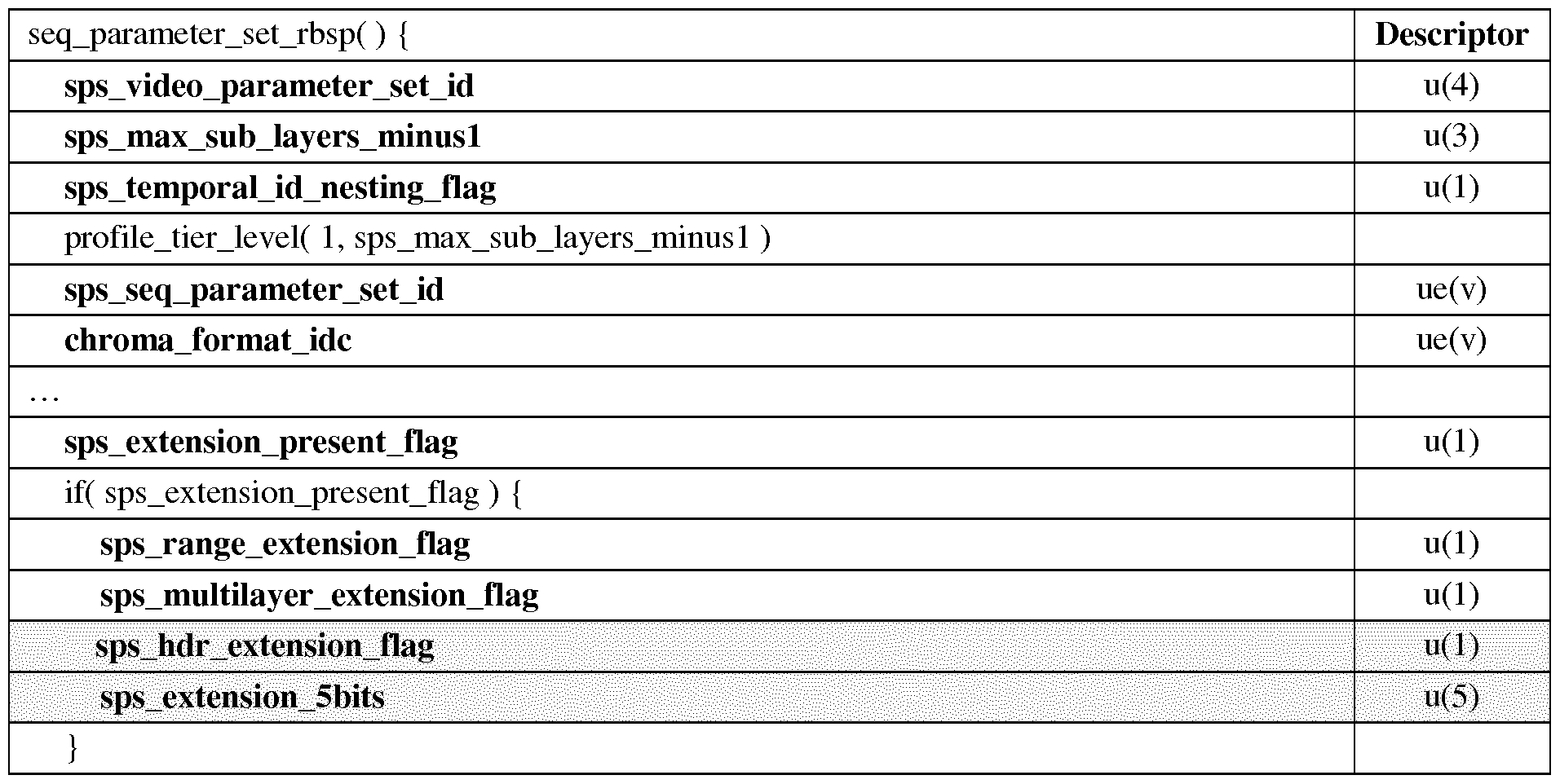
15
if( sps_range_extension_flag )
sps_range_extension( )
if( sps_multilayer_extension_flag )
sps_multilayer_extension( ) /* specified in Annex F */
if( sps_hdr_extension_flag )
sps_hdr_extension( ) /* specified in Annex X */
if( sps_extension_5bits )
while( more_rbsp_data( ) )
sps_extension_data_flag u(l) rbsp_trailing_bits( )
}
TABLE 8 Sequence parameter set high dynamic range extension syntax

[59] TABLE 6 can be modified as shown in TABLE 9 to insert modulation value into a header:
TABLE 9 Picture parameter set high dynamic range extension syntax

[60] Semantics modulation_val_present_flag equal to 1 specifies that log2_modulation_val_denom and modulation_val_minusl are present in the slice segment headers referring to the PPS. modulation_val_present_flag equal to 0 specifies that log2_modulation_val_denom and modulation_val_minusl are not present in the slice segment headers referring to the PPS. When not present the value of modulation_val_present_flag is inferred to be equal to 0.
[61] In another embodiment, the modulation value can also be inserted into a header as shown in TABLE 10.
TABLE 10 General slice se ment header s ntax

16

[62] TABLE 11 describes an example of inserting the modulation value into VUI. When VUI is already defined in an existing standard (for example, H.264/AVC or HEVC) without extension potential, inserting the modulation value information into VUI may break compliance with existing devices unlike previous embodiments. In addition, as VUI is defined as part of SPS, it may not have the temporal flexibility to achieve picture- wise adaptation.
TABLE 11 General Video Usability Information syntax

17

[63] In the above, we discussed inserting the modulation value into various syntax structures, using H.265/HEVC as an example. The present principles can be applied to other standards. [64] Except the VUI implementation, a decoder in a non-HDR architecture or service is able to get the SDR video just by decoding the SDR bitstream without decoding modulation values. Advantageously, the coded Ba is by design discarded by SDR decoders, in order to preserve full backward compatibility with the existing or deployed SDR workflow.
[65] Syntax and semantics for signaling modulation values are discussed above. As understood by those skilled in the art, they could be used to guide the decoding process and/or encoding process of the modulation value information, for example, they could be used to guide the encoding at step 230 of method 200, and to guide the decoding at step 320 of method 300.
[66] FIG. 5 illustrates a block diagram of an exemplary system in which various aspects of the exemplary embodiments of the present principles may be implemented. System 500 may be embodied as a device including the various components described below and is configured to perform the processes described above. Examples of such devices, include, but are not limited to, personal computers, laptop computers, smartphones, tablet computers, digital multimedia set top boxes, digital television receivers, personal video recording systems, connected home appliances, and servers. System 500 may be communicatively coupled to other similar systems, and to a display via a communication channel as shown in FIG. 5 and as known by those skilled in the art to implement the exemplary video system described above.
[67] The system 500 may include at least one processor 510 configured to execute
18
instructions loaded therein for implementing the various processes as discussed above. Processor 510 may include embedded memory, input output interface and various other circuitries as known in the art. The system 500 may also include at least one memory 520 (e.g., a volatile memory device, a non-volatile memory device). System 500 may additionally include a storage device 540, which may include non- volatile memory, including, but not limited to, EEPROM, ROM, PROM, RAM, DRAM, SRAM, flash, magnetic disk drive, and/or optical disk drive. The storage device 540 may comprise an internal storage device, an attached storage device and/or a network accessible storage device, as non-limiting examples. System 500 may also include an encoder/decoder module 530 configured to process data to provide an encoded video or decoded video.
[68] Encoder/decoder module 530 represents the module(s) that may be included in a device to perform the encoding and/or decoding functions. As is known, a device may include one or both of the encoding and decoding modules. Additionally, encoder/decoder module 530 may be implemented as a separate element of system 500 or may be incorporated within processors 510 as a combination of hardware and software as known to those skilled in the art.
[69] Program code to be loaded onto processors 510 to perform the various processes described hereinabove may be stored in storage device 540 and subsequently loaded onto memory 520 for execution by processors 510. In accordance with the exemplary embodiments of the present principles, one or more of the processor(s) 510, memory 520, storage device 540 and encoder/decoder module 530 may store one or more of the various items during the performance of the processes discussed herein above, including, but not limited to the modulation value, the SDR video, the HDR video, equations, formula, matrices, variables, operations, and operational logic. [70] The system 500 may also include communication interface 550 that enables communication with other devices via communication channel 560. The communication interface 550 may include, but is not limited to a transceiver configured to transmit and receive data from communication channel 560. The communication interface may include, but is not limited to, a modem or network card and the communication channel may be implemented within a wired and/or wireless medium. The various components of system 500 may be connected or communicatively coupled together using various suitable connections, including, but not limited to internal buses, wires, and printed circuit boards.
19
[71] The exemplary embodiments according to the present principles may be carried out by computer software implemented by the processor 510 or by hardware, or by a combination of hardware and software. As a non-limiting example, the exemplary embodiments according to the present principles may be implemented by one or more integrated circuits. The memory 520 may be of any type appropriate to the technical environment and may be implemented using any appropriate data storage technology, such as optical memory devices, magnetic memory devices, semiconductor-based memory devices, fixed memory and removable memory, as non-limiting examples. The processor 510 may be of any type appropriate to the technical environment, and may encompass one or more of microprocessors, general purpose computers, special purpose computers and processors based on a multi-core architecture, as non-limiting examples.
[72] Referring to FIG. 6, a data transmission system 600 is shown, to which the features and principles described above may be applied. The data transmission system 600 may be, for example, a head-end or transmission system for transmitting a signal using any of a variety of media, such as, satellite, cable, telephone-line, or terrestrial broadcast. The data transmission system 600 also may be used to provide a signal for storage. The transmission may be provided over the Internet or some other network. The data transmission system 600 is capable of generating and delivering, for example, video content and other content.
[73] The data transmission system 600 receives processed data and other information from a processor 601. In one implementation, the processor 601 generates the HDR video and/or represents an HDR picture using a single modulation value and an SDR picture representative of the HDR picture. The processor 601 may also provide metadata to 600 indicating, for example, the function used in the mapping curves or the values of constants.
[74] The data transmission system or apparatus 600 includes an encoder 602 and a transmitter 604 capable of transmitting the encoded signal. The encoder 602 receives data information from the processor 601. The encoder 602 generates an encoded signal(s). Then encoder 602 may use, for example, method 200 as described in FIG. 2.
[75] The encoder 602 may include sub-modules, including for example an assembly unit for receiving and assembling various pieces of information into a structured format for storage or transmission. The various pieces of information may include, for example, coded or uncoded video, and coded or uncoded elements. In some implementations, the encoder
20
602 includes the processor 601 and therefore performs the operations of the processor 601.
[76] The transmitter 604 receives the encoded signal(s) from the encoder 602 and transmits the encoded signal(s) in one or more output signals. The transmitter 604 may be, for example, adapted to transmit a program signal having one or more bitstreams representing encoded pictures and/or information related thereto. Typical transmitters perform functions such as, for example, one or more of providing error-correction coding, interleaving the data in the signal, randomizing the energy in the signal, and modulating the signal onto one or more carriers using a modulator 606. The transmitter 604 may include, or interface with, an antenna (not shown). Further, implementations of the transmitter 604 may be limited to the modulator 606.
[77] The data transmission system 600 is also communicatively coupled to a storage unit 608. In one implementation, the storage unit 608 is coupled to the encoder 602, and stores an encoded bitstream from the encoder 602. In another implementation, the storage unit 608 is coupled to the transmitter 604, and stores a bitstream from the transmitter 604. The bitstream from the transmitter 604 may include, for example, one or more encoded bitstreams that have been further processed by the transmitter 604. The storage unit 608 is, in different implementations, one or more of a standard DVD, a Blu-Ray disc, a hard drive, or some other storage device.
[78] Referring to FIG. 7, a data receiving system 700 is shown to which the features and principles described above may be applied. The data receiving system 700 may be configured to receive signals over a variety of media, such as storage device, satellite, cable, telephone-line, or terrestrial broadcast. The signals may be received over the Internet or some other network.
[79] The data receiving system 700 may be, for example, a cell-phone, a computer, a set-top box, a television, or other device that receives encoded video and provides, for example, decoded video signal for display (display to a user, for example), for processing, or for storage. Thus, the data receiving system 700 may provide its output to, for example, a screen of a television, a computer monitor, a computer (for storage, processing, or display), or some other storage, processing, or display device. [80] The data receiving system 700 is capable of receiving and processing data information. The data receiving system or apparatus 700 includes a receiver 702 for receiving an encoded
21
signal, such as, for example, the signals described in the implementations of this application. The receiver 702 may receive, for example, a signal providing one or more of the HDR and SDR videos, or a signal output from the data transmission system 600 of FIG. 6.
[81] The receiver 702 may be, for example, adapted to receive a program signal having a plurality of bitstreams representing encoded HDR pictures. Typical receivers perform functions such as, for example, one or more of receiving a modulated and encoded data signal, demodulating the data signal from one or more carriers using a demodulator 704, de-randomizing the energy in the signal, de-interleaving the data in the signal, and error-correction decoding the signal. The receiver 702 may include, or interface with, an antenna (not shown). Implementations of the receiver 702 may be limited to the demodulator 704.
[82] The data receiving system 700 includes a decoder 706. The receiver 702 provides a received signal to the decoder 706. The signal provided to the decoder 706 by the receiver 702 may include one or more encoded bitstreams. The decoder 706 outputs a decoded signal, such as, for example, decoded video signals including video information.
[83] The data receiving system or apparatus 700 is also communicatively coupled to a storage unit 707. In one implementation, the storage unit 707 is coupled to the receiver 702, and the receiver 702 accesses a bitstream from the storage unit 707. In another implementation, the storage unit 707 is coupled to the decoder 706, and the decoder 706 accesses a bitstream from the storage unit 707. The bitstream accessed from the storage unit 707 includes, in different implementations, one or more encoded bitstreams. The storage unit 707 is, in different implementations, one or more of a standard DVD, a Blu-Ray disc, a hard drive, or some other storage device.
[84] The output data from the decoder 706 is provided, in one implementation, to a processor 708. The processor 708 is, in one implementation, a processor configured for performing the SDR to HDR mapping. In some implementations, the decoder 706 includes the processor 708 and therefore performs the operations of the processor 708. In other implementations, the processor 708 is part of a downstream device such as, for example, a set-top box or a television. [85] The implementations described herein may be implemented in, for example, a method or a process, an apparatus, a software program, a data stream, or a signal. Even if only
22
discussed in the context of a single form of implementation (for example, discussed only as a method), the implementation of features discussed may also be implemented in other forms (for example, an apparatus or program). An apparatus may be implemented in, for example, appropriate hardware, software, and firmware. The methods may be implemented in, for example, an apparatus such as, for example, a processor, which refers to processing devices in general, including, for example, a computer, a microprocessor, an integrated circuit, or a programmable logic device. Processors also include communication devices, such as, for example, computers, cell phones, portable/personal digital assistants ("PDAs"), and other devices that facilitate communication of information between end-users. [86] Reference to "one embodiment" or "an embodiment" or "one implementation" or "an implementation" of the present principles, as well as other variations thereof, mean that a particular feature, structure, characteristic, and so forth described in connection with the embodiment is included in at least one embodiment of the present principles. Thus, the appearances of the phrase "in one embodiment" or "in an embodiment" or "in one implementation" or "in an implementation", as well any other variations, appearing in various places throughout the specification are not necessarily all referring to the same embodiment.
[87] Additionally, this application or its claims may refer to "determining" various pieces of information. Determining the information may include one or more of, for example, estimating the information, calculating the information, predicting the information, or retrieving the information from memory.
[88] Further, this application or its claims may refer to "accessing" various pieces of information. Accessing the information may include one or more of, for example, receiving the information, retrieving the information (for example, from memory), storing the information, processing the information, transmitting the information, moving the information, copying the information, erasing the information, calculating the information, determining the information, predicting the information, or estimating the information.
[89] Additionally, this application or its claims may refer to "receiving" various pieces of information. Receiving is, as with "accessing", intended to be a broad term. Receiving the information may include one or more of, for example, accessing the information, or retrieving the information (for example, from memory). Further, "receiving" is typically involved, in one way or another, during operations such as, for example, storing the information,
23
processing the information, transmitting the information, moving the information, copying the information, erasing the information, calculating the information, determining the information, predicting the information, or estimating the information.
[90] As will be evident to one of skill in the art, implementations may produce a variety of signals formatted to carry information that may be, for example, stored or transmitted. The information may include, for example, instructions for performing a method, or data produced by one of the described implementations. For example, a signal may be formatted to carry the bitstream of a described embodiment. Such a signal may be formatted, for example, as an electromagnetic wave (for example, using a radio frequency portion of spectrum) or as a baseband signal. The formatting may include, for example, encoding a data stream and modulating a carrier with the encoded data stream. The information that the signal carries may be, for example, analog or digital information. The signal may be transmitted over a variety of different wired or wireless links, as is known. The signal may be stored on a processor-readable medium.
24
Claims
1. A method for decoding a bitstream including a High Dynamic Range (HDR) picture, comprising:
determining (320) a modulation value from at least one syntax element included in the bitstream; and
determining (330) the HDR picture responsive to the determined modulation value and a Standard Dynamic Range (SDR) picture included in the bitstream.
2. The method of claim 1, wherein the at least one syntax element is included in at least one of a Picture Parameter Set, a Sequence Parameter Set, a Supplemental
Enhancement Information (SEI) message, a Video Usability Information (VUI), and a header.
3. The method of claim 1, wherein the HDR picture is included in an HDR video, and wherein the modulation value is decoded for each HDR picture in the HDR video.
4. The method of claim 1, wherein the determining the modulation value comprises:
decoding a first syntax element and a second syntax element, the first syntax element indicative of a base-2 logarithm of a denominator for the modulation value, and the second syntax element indicative of a numerator for the modulation value; and
determining the modulation value responsive to the first syntax element and the second syntax element.
5. The method of claim 1, wherein a single modulation value is determined from the bitstream for one of (1) the HDR picture; (2) a slice of the HDR picture; and (3) a tile of the HDR picture.
6. The method of claim 1, wherein the SDR picture is representative of the HDR picture.
7. An apparatus for decoding a bitstream including a High Dynamic Range (HDR) picture, comprising:
a communication interface (550) configured to access the bitstream; and
25
a decoder (530) configured to
determine a modulation value from at least one syntax element included in the bitstream, and
determine the HDR picture responsive to the determined modulation value and a Standard Dynamic Range (SDR) picture included in the bitstream.
8. The apparatus of claim 7, wherein the at least one syntax element is included in at least one of a Picture Parameter Set, a Sequence Parameter Set, a Supplemental Enhancement Information (SEI) message, a Video Usability Information (VUI), and a header.
9. The apparatus of claim 7, wherein the HDR picture is included in an HDR video, and wherein the modulation value is decoded for each HDR picture in the HDR video.
10. The apparatus of claim 7, wherein the decoder is configured to decode a first syntax element and a second syntax element in order to determine the modulation value, the first syntax element indicative of a base-2 logarithm of a denominator for the modulation value, and the second syntax element indicative of a numerator for the modulation value.
11. The apparatus of claim 7, wherein a single modulation value is determined from the bitstream for one of (1) the HDR picture; (2) a slice of the HDR picture; and (3) a tile of the HDR picture.
12. The apparatus of claim 7, wherein the SDR picture is representative of the HDR picture.
13. A non-transitory computer readable storage medium having stored thereon instructions for decoding a bitstream including a High Dynamic Range (HDR) picture, the instructions causing a processor to perform at least:
determining a modulation value from at least one syntax element included in the bitstream; and
determining the HDR picture responsive to the determined modulation value and a Standard Dynamic Range (SDR) picture included in the bitstream.
26
Applications Claiming Priority (2)
| Application Number | Priority Date | Filing Date | Title |
|---|---|---|---|
| EP15305108.1 | 2015-01-30 | ||
| EP15305108.1A EP3051486A1 (en) | 2015-01-30 | 2015-01-30 | Method and apparatus for encoding and decoding high dynamic range (HDR) videos |
Publications (1)
| Publication Number | Publication Date |
|---|---|
| WO2016120424A1 true WO2016120424A1 (en) | 2016-08-04 |
Family
ID=52473825
Family Applications (1)
| Application Number | Title | Priority Date | Filing Date |
|---|---|---|---|
| PCT/EP2016/051877 Ceased WO2016120424A1 (en) | 2015-01-30 | 2016-01-29 | Method and apparatus for encoding and decoding high dynamic range (hdr) videos |
Country Status (3)
| Country | Link |
|---|---|
| EP (1) | EP3051486A1 (en) |
| TW (1) | TW201638879A (en) |
| WO (1) | WO2016120424A1 (en) |
Cited By (6)
| Publication number | Priority date | Publication date | Assignee | Title |
|---|---|---|---|---|
| CN108513134A (en) * | 2017-02-24 | 2018-09-07 | 汤姆逊许可公司 | According to the method and apparatus of decoded image data reconstructed image data |
| CN111667418A (en) * | 2016-08-22 | 2020-09-15 | 华为技术有限公司 | Method and apparatus for image processing |
| US10803562B2 (en) * | 2016-03-18 | 2020-10-13 | Koninklijke Philips N.V. | Encoding and decoding HDR videos |
| TWI713354B (en) * | 2016-08-09 | 2020-12-11 | 美商高通公司 | Color remapping information sei message signaling for display adaptation |
| WO2023125467A1 (en) * | 2021-12-30 | 2023-07-06 | 北京字跳网络技术有限公司 | Image processing method and apparatus, electronic device and readable storage medium |
| WO2025081582A1 (en) * | 2023-10-17 | 2025-04-24 | 华为技术有限公司 | Video metadata transmission method and device |
Families Citing this family (8)
| Publication number | Priority date | Publication date | Assignee | Title |
|---|---|---|---|---|
| KR102308192B1 (en) * | 2017-03-09 | 2021-10-05 | 삼성전자주식회사 | Display apparatus and control method thereof |
| CN108933768B (en) * | 2017-05-27 | 2021-06-08 | 成都鼎桥通信技术有限公司 | Method and device for acquiring sending frame rate of video frame |
| CN108074220B (en) * | 2017-12-11 | 2020-07-14 | 上海顺久电子科技有限公司 | Image processing method and device and television |
| CN108573287B (en) * | 2018-05-11 | 2021-10-29 | 浙江工业大学 | A training method of image codec based on deep neural network |
| CN109218095B (en) * | 2018-09-18 | 2021-07-23 | 鹰视云(深圳)科技有限公司 | An intelligent wireless cloud SDR platform architecture and its reconstruction method |
| WO2021170091A1 (en) * | 2020-02-29 | 2021-09-02 | Beijing Bytedance Network Technology Co., Ltd. | Constrains for high level syntax elements |
| WO2021208896A1 (en) | 2020-04-13 | 2021-10-21 | Beijing Bytedance Network Technology Co., Ltd. | Signalling of flags in picture parameter set |
| WO2021233449A1 (en) | 2020-05-22 | 2021-11-25 | Beijing Bytedance Network Technology Co., Ltd. | Reserved bits in general constraint information of a video |
Citations (2)
| Publication number | Priority date | Publication date | Assignee | Title |
|---|---|---|---|---|
| EP1827024A1 (en) * | 2006-02-24 | 2007-08-29 | Sharp Kabushiki Kaisha | High dynamic range video coding |
| EP2406959A1 (en) * | 2009-03-13 | 2012-01-18 | Dolby Laboratories Licensing Corporation | Layered compression of high dynamic range, visual dynamic range, and wide color gamut video |
-
2015
- 2015-01-30 EP EP15305108.1A patent/EP3051486A1/en not_active Withdrawn
-
2016
- 2016-01-29 WO PCT/EP2016/051877 patent/WO2016120424A1/en not_active Ceased
- 2016-01-30 TW TW105103049A patent/TW201638879A/en unknown
Patent Citations (2)
| Publication number | Priority date | Publication date | Assignee | Title |
|---|---|---|---|---|
| EP1827024A1 (en) * | 2006-02-24 | 2007-08-29 | Sharp Kabushiki Kaisha | High dynamic range video coding |
| EP2406959A1 (en) * | 2009-03-13 | 2012-01-18 | Dolby Laboratories Licensing Corporation | Layered compression of high dynamic range, visual dynamic range, and wide color gamut video |
Non-Patent Citations (1)
| Title |
|---|
| SEGALL A ET AL: "Tone mapping SEI", 19. JVT MEETING; 31-03-2006 - 07-04-2006; GENEVA, CH; (JOINT VIDEOTEAM OF ISO/IEC JTC1/SC29/WG11 AND ITU-T SG.16 ),, no. JVT-S087, 1 April 2006 (2006-04-01), XP030006466, ISSN: 0000-0409 * |
Cited By (10)
| Publication number | Priority date | Publication date | Assignee | Title |
|---|---|---|---|---|
| US10803562B2 (en) * | 2016-03-18 | 2020-10-13 | Koninklijke Philips N.V. | Encoding and decoding HDR videos |
| US11593922B2 (en) | 2016-03-18 | 2023-02-28 | Koninklijke Philips N.V. | Encoding and decoding HDR videos |
| US11887285B2 (en) | 2016-03-18 | 2024-01-30 | Koninklijke Philips N.V. | Encoding and decoding HDR videos |
| TWI713354B (en) * | 2016-08-09 | 2020-12-11 | 美商高通公司 | Color remapping information sei message signaling for display adaptation |
| CN111667418A (en) * | 2016-08-22 | 2020-09-15 | 华为技术有限公司 | Method and apparatus for image processing |
| CN108513134A (en) * | 2017-02-24 | 2018-09-07 | 汤姆逊许可公司 | According to the method and apparatus of decoded image data reconstructed image data |
| CN108513134B (en) * | 2017-02-24 | 2023-05-26 | 交互数字Vc控股公司 | Method and device for reconstructing image data from decoded image data |
| WO2023125467A1 (en) * | 2021-12-30 | 2023-07-06 | 北京字跳网络技术有限公司 | Image processing method and apparatus, electronic device and readable storage medium |
| US12439012B2 (en) | 2021-12-30 | 2025-10-07 | Beijing Zitiao Network Technology Co., Ltd. | Image processing method and apparatus, electronic device and readable storage medium |
| WO2025081582A1 (en) * | 2023-10-17 | 2025-04-24 | 华为技术有限公司 | Video metadata transmission method and device |
Also Published As
| Publication number | Publication date |
|---|---|
| TW201638879A (en) | 2016-11-01 |
| EP3051486A1 (en) | 2016-08-03 |
Similar Documents
| Publication | Publication Date | Title |
|---|---|---|
| US10356444B2 (en) | Method and apparatus for encoding and decoding high dynamic range (HDR) videos | |
| EP3051486A1 (en) | Method and apparatus for encoding and decoding high dynamic range (HDR) videos | |
| US12028523B2 (en) | System and method for reshaping and adaptation of high dynamic range video data | |
| JP7053722B2 (en) | A method and apparatus for signaling a picture / video format of an LDR picture within a bitstream and a picture / video format of a decoded HDR picture obtained from this LDR picture and an illumination picture. | |
| US10999607B2 (en) | Methods, systems and apparatus for electro-optical and opto-electrical conversion of images and video | |
| CN111316625B (en) | Method and apparatus for generating a second image from a first image | |
| CN107258082B (en) | Method and apparatus for encoding color mapping information and processing images based on color mapping information | |
| CN111434114B (en) | Processing images | |
| EP3051823A1 (en) | Methods, systems and aparatus for electro-optical and opto-electrical conversion of images and video | |
| EP3054417A1 (en) | Method and apparatus for encoding and decoding high dynamic range images | |
| CN116508054B (en) | Methods, apparatus, and devices for avoiding chroma clipping in tone mappers while maintaining saturation and preserving hue. | |
| KR102280094B1 (en) | Method for generating a bitstream relative to image/video signal, bitstream carrying specific information data and method for obtaining such specific information | |
| EP4637148A1 (en) | Method and device for encoding and decoding attenuation map for energy aware images | |
| CN120419190A (en) | Method and apparatus for encoding and decoding an attenuation map for an energy-aware image | |
| EP4696022A1 (en) | Method and device for encoding and decoding attenuation map based on green mpeg for energy aware images | |
| WO2024213421A1 (en) | Method and device for energy reduction of visual content based on attenuation map using mpeg display adaptation | |
| EP3528201A1 (en) | Method and device for controlling saturation in a hdr image |
Legal Events
| Date | Code | Title | Description |
|---|---|---|---|
| 121 | Ep: the epo has been informed by wipo that ep was designated in this application |
Ref document number: 16702094 Country of ref document: EP Kind code of ref document: A1 |
|
| NENP | Non-entry into the national phase |
Ref country code: DE |
|
| 122 | Ep: pct application non-entry in european phase |
Ref document number: 16702094 Country of ref document: EP Kind code of ref document: A1 |