WO2016118499A1 - Visual localization within lidar maps - Google Patents
Visual localization within lidar maps Download PDFInfo
- Publication number
- WO2016118499A1 WO2016118499A1 PCT/US2016/013896 US2016013896W WO2016118499A1 WO 2016118499 A1 WO2016118499 A1 WO 2016118499A1 US 2016013896 W US2016013896 W US 2016013896W WO 2016118499 A1 WO2016118499 A1 WO 2016118499A1
- Authority
- WO
- WIPO (PCT)
- Prior art keywords
- lidar
- camera
- localization
- data
- map information
- Prior art date
Links
- 230000004807 localization Effects 0.000 title claims abstract description 49
- 230000000007 visual effect Effects 0.000 title claims abstract description 29
- 238000000034 method Methods 0.000 claims abstract description 34
- 238000012545 processing Methods 0.000 claims abstract description 9
- 238000005259 measurement Methods 0.000 description 11
- 238000002310 reflectometry Methods 0.000 description 11
- 238000013459 approach Methods 0.000 description 9
- 238000013507 mapping Methods 0.000 description 6
- 238000009826 distribution Methods 0.000 description 4
- 238000002474 experimental method Methods 0.000 description 4
- 238000001914 filtration Methods 0.000 description 4
- 238000005457 optimization Methods 0.000 description 4
- 230000008569 process Effects 0.000 description 3
- 230000000135 prohibitive effect Effects 0.000 description 3
- HPTJABJPZMULFH-UHFFFAOYSA-N 12-[(Cyclohexylcarbamoyl)amino]dodecanoic acid Chemical compound OC(=O)CCCCCCCCCCCNC(=O)NC1CCCCC1 HPTJABJPZMULFH-UHFFFAOYSA-N 0.000 description 2
- 230000008901 benefit Effects 0.000 description 2
- 230000000875 corresponding effect Effects 0.000 description 2
- 238000005516 engineering process Methods 0.000 description 2
- 239000011159 matrix material Substances 0.000 description 2
- 238000011160 research Methods 0.000 description 2
- 239000007787 solid Substances 0.000 description 2
- 230000003068 static effect Effects 0.000 description 2
- 238000009825 accumulation Methods 0.000 description 1
- 230000003190 augmentative effect Effects 0.000 description 1
- 238000010276 construction Methods 0.000 description 1
- 238000012937 correction Methods 0.000 description 1
- 230000002596 correlated effect Effects 0.000 description 1
- 230000007812 deficiency Effects 0.000 description 1
- 238000001514 detection method Methods 0.000 description 1
- 238000002059 diagnostic imaging Methods 0.000 description 1
- 239000006185 dispersion Substances 0.000 description 1
- 230000000694 effects Effects 0.000 description 1
- 238000011156 evaluation Methods 0.000 description 1
- 238000009472 formulation Methods 0.000 description 1
- 238000009499 grossing Methods 0.000 description 1
- 238000005286 illumination Methods 0.000 description 1
- 239000003550 marker Substances 0.000 description 1
- 239000000203 mixture Substances 0.000 description 1
- 238000012986 modification Methods 0.000 description 1
- 230000004048 modification Effects 0.000 description 1
- 230000008447 perception Effects 0.000 description 1
- 238000009877 rendering Methods 0.000 description 1
- 230000004044 response Effects 0.000 description 1
- 230000003319 supportive effect Effects 0.000 description 1
- 230000001629 suppression Effects 0.000 description 1
- 238000012360 testing method Methods 0.000 description 1
- 238000012546 transfer Methods 0.000 description 1
- 230000001131 transforming effect Effects 0.000 description 1
- 230000007704 transition Effects 0.000 description 1
- 238000013519 translation Methods 0.000 description 1
- 238000012800 visualization Methods 0.000 description 1
Classifications
-
- G—PHYSICS
- G05—CONTROLLING; REGULATING
- G05D—SYSTEMS FOR CONTROLLING OR REGULATING NON-ELECTRIC VARIABLES
- G05D1/00—Control of position, course or altitude of land, water, air, or space vehicles, e.g. automatic pilot
- G05D1/02—Control of position or course in two dimensions
- G05D1/021—Control of position or course in two dimensions specially adapted to land vehicles
- G05D1/0231—Control of position or course in two dimensions specially adapted to land vehicles using optical position detecting means
- G05D1/0246—Control of position or course in two dimensions specially adapted to land vehicles using optical position detecting means using a video camera in combination with image processing means
- G05D1/0248—Control of position or course in two dimensions specially adapted to land vehicles using optical position detecting means using a video camera in combination with image processing means in combination with a laser
-
- G—PHYSICS
- G05—CONTROLLING; REGULATING
- G05D—SYSTEMS FOR CONTROLLING OR REGULATING NON-ELECTRIC VARIABLES
- G05D1/00—Control of position, course or altitude of land, water, air, or space vehicles, e.g. automatic pilot
- G05D1/02—Control of position or course in two dimensions
- G05D1/021—Control of position or course in two dimensions specially adapted to land vehicles
- G05D1/0268—Control of position or course in two dimensions specially adapted to land vehicles using internal positioning means
- G05D1/0274—Control of position or course in two dimensions specially adapted to land vehicles using internal positioning means using mapping information stored in a memory device
-
- G—PHYSICS
- G06—COMPUTING; CALCULATING OR COUNTING
- G06T—IMAGE DATA PROCESSING OR GENERATION, IN GENERAL
- G06T7/00—Image analysis
- G06T7/70—Determining position or orientation of objects or cameras
- G06T7/73—Determining position or orientation of objects or cameras using feature-based methods
- G06T7/74—Determining position or orientation of objects or cameras using feature-based methods involving reference images or patches
-
- G—PHYSICS
- G06—COMPUTING; CALCULATING OR COUNTING
- G06T—IMAGE DATA PROCESSING OR GENERATION, IN GENERAL
- G06T7/00—Image analysis
- G06T7/70—Determining position or orientation of objects or cameras
- G06T7/73—Determining position or orientation of objects or cameras using feature-based methods
- G06T7/75—Determining position or orientation of objects or cameras using feature-based methods involving models
-
- G—PHYSICS
- G06—COMPUTING; CALCULATING OR COUNTING
- G06T—IMAGE DATA PROCESSING OR GENERATION, IN GENERAL
- G06T2207/00—Indexing scheme for image analysis or image enhancement
- G06T2207/10—Image acquisition modality
- G06T2207/10016—Video; Image sequence
-
- G—PHYSICS
- G06—COMPUTING; CALCULATING OR COUNTING
- G06T—IMAGE DATA PROCESSING OR GENERATION, IN GENERAL
- G06T2207/00—Indexing scheme for image analysis or image enhancement
- G06T2207/10—Image acquisition modality
- G06T2207/10028—Range image; Depth image; 3D point clouds
-
- G—PHYSICS
- G06—COMPUTING; CALCULATING OR COUNTING
- G06T—IMAGE DATA PROCESSING OR GENERATION, IN GENERAL
- G06T2207/00—Indexing scheme for image analysis or image enhancement
- G06T2207/20—Special algorithmic details
- G06T2207/20072—Graph-based image processing
-
- G—PHYSICS
- G06—COMPUTING; CALCULATING OR COUNTING
- G06T—IMAGE DATA PROCESSING OR GENERATION, IN GENERAL
- G06T2207/00—Indexing scheme for image analysis or image enhancement
- G06T2207/20—Special algorithmic details
- G06T2207/20076—Probabilistic image processing
-
- G—PHYSICS
- G06—COMPUTING; CALCULATING OR COUNTING
- G06T—IMAGE DATA PROCESSING OR GENERATION, IN GENERAL
- G06T2207/00—Indexing scheme for image analysis or image enhancement
- G06T2207/30—Subject of image; Context of image processing
- G06T2207/30244—Camera pose
-
- G—PHYSICS
- G06—COMPUTING; CALCULATING OR COUNTING
- G06T—IMAGE DATA PROCESSING OR GENERATION, IN GENERAL
- G06T2207/00—Indexing scheme for image analysis or image enhancement
- G06T2207/30—Subject of image; Context of image processing
- G06T2207/30248—Vehicle exterior or interior
-
- G—PHYSICS
- G06—COMPUTING; CALCULATING OR COUNTING
- G06T—IMAGE DATA PROCESSING OR GENERATION, IN GENERAL
- G06T2207/00—Indexing scheme for image analysis or image enhancement
- G06T2207/30—Subject of image; Context of image processing
- G06T2207/30248—Vehicle exterior or interior
- G06T2207/30252—Vehicle exterior; Vicinity of vehicle
Definitions
- the present disclosure relates to visual localization and, more particularly, relates to visual localization within LIDAR maps using correlated real-time visual images.
- GPU GPU
- 3D prior maps constructed by a survey vehicle equipped with 3D LIDAR scanners are used for vehicle automation.
- a vehicle is localized by comparing imagery from a monocular camera against several candidate views, seeking to maximize normalized mutual information (NMI) (as outlined in Fig. 1 ).
- NMI normalized mutual information
- a GPU implementation that can provide real-time localization at ⁇ 10 Hz is provided.
- FIG. 1 illustrates an overview of our proposed visual localization system.
- FIG. 2 is a factor graph of the pose-graph SLAM problem that we solve in the off-line mapping stage to develop a prior map for localization.
- FIGS. 3A-3C illustrate a sample ground mesh used to generate synthetic views of the environment.
- FIG. 3A shows a 400 m x 300 m ground mesh colored by surface reflectivity, with a zoomed in view shown in FIG. 3B (this region is highlighted in red in FIG. 3A)).
- FIG. 4 are photos of sample synthetic views generated by our OpenGL pipeline.
- FIG. 5 are photos of sample pre-warping applied to images to reduce the overall search space for image registration.
- FIGS. 6A-6C are successful image registrations.
- FIGS. 7A-7C are failure modes of image registration.
- FIGS. 8A-8B are longitudinal and lateral errors in our image registration, sampled at each second of our trajectory; larger and brighter markers indicate regions where image registration produced higher errors longitudinally (FIG. 8A) or laterally (FIG. 8B).
- FIG. 9 are histograms of longitudinal and lateral errors.
- FIGS. 10A-10B show localization accuracy in terms of longitudinal and lateral error relative to SLAM-optimized ground-truth over time.
- Example embodiments are provided so that this disclosure will be thorough, and will fully convey the scope to those who are skilled in the art. Numerous specific details are set forth such as examples of specific components, devices, and methods, to provide a thorough understanding of embodiments of the present disclosure. It will be apparent to those skilled in the art that specific details need not be employed, that example embodiments may be embodied in many different forms and that neither should be construed to limit the scope of the disclosure. In some example embodiments, well-known processes, well-known device structures, and well-known technologies are not described in detail.
- first, second, third, etc. may be used herein to describe various elements, components, regions, layers and/or sections, these elements, components, regions, layers and/or sections should not be limited by these terms. These terms may be only used to distinguish one element, component, region, layer or section from another region, layer or section. Terms such as “first,” “second,” and other numerical terms when used herein do not imply a sequence or order unless clearly indicated by the context. Thus, a first element, component, region, layer or section discussed below could be termed a second element, component, region, layer or section without departing from the teachings of the example embodiments.
- Spatially relative terms such as “inner,” “outer,” “beneath,” “below,” “lower,” “above,” “upper,” and the like, may be used herein for ease of description to describe one element or feature's relationship to another element(s) or feature(s) as illustrated in the figures. Spatially relative terms may be intended to encompass different orientations of the device in use or operation in addition to the orientation depicted in the figures. For example, if the device in the figures is turned over, elements described as “below” or “beneath” other elements or features would then be oriented “above” the other elements or features. Thus, the example term “below” can encompass both an orientation of above and below. The device may be otherwise oriented (rotated 90 degrees or at other orientations) and the spatially relative descriptors used herein interpreted accordingly.
- Next-Generation Automated Driving Platform research of the present teachings has enabled precise, lane-level localization supportive of automated driving or active-safety applications by using commodity cameras.
- the position of the vehicle is corrected to centimeter-level accuracy using map matching of live camera imagery to a 3D prior map information.
- the proposed method leverages a graphics processing unit (GPU) so that several synthetic, pin-hole camera images can be generated, which can then be directly compared against streaming vehicle imagery.
- GPU graphics processing unit
- the first part of our localization framework is the offline mapping stage, which generates the map to be used for online localization.
- Our goal here is to generate a map that is metrically accurate to the surrounding structure.
- our survey vehicle Prior to the offline mapping stage, our survey vehicle has no a priori knowledge of the environment, thus, we employ SLAM to build a model of the environment.
- GPS global positioning system
- Algorithm 1 Pose-Graph to Ground-Mesh
- the goal of our image registration problem is to, given some initial pose prior x k , find some relative offset ⁇ ; that optimally aligns the projected map, Pj, against our camera measurements, C k .
- This optimization is framed as a local search problem within the vicinity of x k and could be done in a brute-force manner by generating a predicted view for the entire dom(x) x dom(y) x dom(6) search volume to avoid local maxima of hill-climbing searches.
- the remainder of this section details our method for generating these predicted views (Pj) and our NMI evaluation metric.
- Mutual information has been successfully used in various fields for registering data from multi-modal sources.
- Mutual information provides a way to statistically measure the mutual dependence between two random variables, A and B.
- mutual information is defined in terms of the marginal and joint entropies of each:
- MI(A, B) H(A) + H(B) - H(A, B)
- EKF Extended Kalman Filter
- ⁇ 3 ⁇ 4 j3 ⁇ 4 + K k (z k - h k (p k ))
- ⁇ k (I - K k H k ) ⁇ k (I - K k H k ) T + K k R k Ki
- F k represents our plant model that integrates measurements from an Applanix IMU with uncertainty Q k _i
- H k is a linear observation model (identity matrix)
- K k is the corrective Kalman gain induced by our image registration measurement z k (with uncertainty R k ).
- the measurement z k is exactly the output of our image registration in (10) and R k is estimated by fitting a covariance to the explored cost surface.
- Our filter is initialized in a global frame from a single dual-antenna GPS measurement with high uncertainty, which provides a rough initial guess of global pose with orientation.
- This dynamic approach allows us to perform an expensive, exhaustive search to initially align to our prior map while avoiding local maxima, then iteratively reduce the search space as our posterior confidence increases.
- Algorithms were implemented using OpenCV, OpenGL, and
Abstract
An apparatus and method for visual localization of a visual camera system outputting real-time visual camera data and a graphics processing unit receiving the real-time visual camera data. The graphics processing unit accesses a database of prior map information and generates a synthetic image that is then compared to the real-time visual camera data to determine corrected position data. The graphics processing unit determines a camera position based on the corrected position data. A corrective system for applying navigation of the vehicle based on the determined camera position can be used in some embodiments.
Description
VISUAL LOCALIZATION WITHIN LIDAR MAPS
CROSS-REFERENCE TO RELATED APPLICATIONS
[0001] This application claims priority to U.S. Utility Application No. 15/000,169, filed on January 19, 2016 and also claims the benefit of U.S. Provisional Application No. 62/104,915, filed on January 19, 2015. The entire disclosures of the above applications are incorporated herein by reference.
FIELD
[0002] The present disclosure relates to visual localization and, more particularly, relates to visual localization within LIDAR maps using correlated real-time visual images.
BACKGROUND AND SUMMARY
[0003] This section provides background information related to the present disclosure which is not necessarily prior art. This section provides a general summary of the disclosure, and is not a comprehensive disclosure of its full scope or all of its features.
[0004] I. Introduction
[0005] In recent years, fully autonomous, self-driving cars have grown into a reality with progress in the simultaneous localization and mapping (SLAM) research community and the advent of consumer-grade three-dimensional (3D) light detection and ranging (LIDAR) scanners. Systems such as the Google driverless car use these LIDAR scanners, combined with high accuracy GPS/INS systems, to enable cars to drive hundreds of thousands of miles without user control.
[0006] In order to navigate autonomously, these robots require precise localization within an a priori known map. Rather than using the vehicle's sensors to explicitly perceive lane markings, traffic signs, etc., metadata is embedded into a prior map, which transforms the difficult perception tasks into a localization problem. State-of-the-art methods use reflectivity measurements from 3D LIDAR scanners to create an orthographic map of ground-plane
reflectivities. Online localization is then performed with the current 3D LIDAR scans and an inertial measurement unit (IMU).
[0007] The cost of 3D LIDAR scanners is prohibitive for consumer grade automobiles. Quite likely the greatest near-term enabler for self-driving cars is the increased use of camera systems in place of expensive LIDAR scanners. Cameras provide a low-cost means to generate extremely rich, dense data that is suitable for localization.
[0008] The present teachings leverage a graphics processing unit
(GPU) so that one can generate several synthetic, pin-hole camera images, which we can then directly compare against streaming vehicle imagery. This differs from other visual localization approaches, which rely on sophisticated feature points. This significantly simpler approach avoids over-engineering the problem by formulating a slightly more computationally expensive solution that is still real-time tractable on a mobile-grade GPU and capable of high accuracy localization.
[0009] According to the present teachings, 3D prior maps (augmented with surface reflectivities) constructed by a survey vehicle equipped with 3D LIDAR scanners are used for vehicle automation. A vehicle is localized by comparing imagery from a monocular camera against several candidate views, seeking to maximize normalized mutual information (NMI) (as outlined in Fig. 1 ). In some embodiments, contributions of the present teachings include:
[0010] · A multi-modal approach that allows the use of LIDAR-based ground maps, which accurately depicts the metric and surface reflectivity of the ground.
[0011] · A projective framework that can predict and evaluate appearance with a single, monocular camera.
[0012] · Benchmarks of visual localization methods with state-of-the- art LIDAR-based localization strategies are provided.
[0013] · A GPU implementation that can provide real-time localization at ~10 Hz is provided.
[0014] Further areas of applicability will become apparent from the description provided herein. The description and specific examples in this
summary are intended for purposes of illustration only and are not intended to limit the scope of the present disclosure.
DRAWINGS
[0015] The drawings described herein are for illustrative purposes only of selected embodiments and not all possible implementations, and are not intended to limit the scope of the present disclosure.
[0016] FIG. 1 illustrates an overview of our proposed visual localization system.
[0017] FIG. 2 is a factor graph of the pose-graph SLAM problem that we solve in the off-line mapping stage to develop a prior map for localization.
[0018] FIGS. 3A-3C illustrate a sample ground mesh used to generate synthetic views of the environment. FIG. 3A shows a 400 m x 300 m ground mesh colored by surface reflectivity, with a zoomed in view shown in FIG. 3B (this region is highlighted in red in FIG. 3A)). We show the same zoomed view, colored by z-height to demonstrate the height variation we are able to capture with our ground-mesh in FIG. 3C - yellow-to-red represents Δζ = 30 cm.
[0019] FIG. 4 are photos of sample synthetic views generated by our OpenGL pipeline.
[0020] FIG. 5 are photos of sample pre-warping applied to images to reduce the overall search space for image registration.
[0021 ] FIGS. 6A-6C are successful image registrations.
[0022] FIGS. 7A-7C are failure modes of image registration.
[0023] FIGS. 8A-8B are longitudinal and lateral errors in our image registration, sampled at each second of our trajectory; larger and brighter markers indicate regions where image registration produced higher errors longitudinally (FIG. 8A) or laterally (FIG. 8B).
[0024] FIG. 9 are histograms of longitudinal and lateral errors.
[0025] FIGS. 10A-10B show localization accuracy in terms of longitudinal and lateral error relative to SLAM-optimized ground-truth over time.
[0026] Corresponding reference numerals indicate corresponding parts throughout the several views of the drawings.
DETAILED DESCRIPTION
[0027] Example embodiments will now be described more fully with reference to the accompanying drawings.
[0028] Example embodiments are provided so that this disclosure will be thorough, and will fully convey the scope to those who are skilled in the art. Numerous specific details are set forth such as examples of specific components, devices, and methods, to provide a thorough understanding of embodiments of the present disclosure. It will be apparent to those skilled in the art that specific details need not be employed, that example embodiments may be embodied in many different forms and that neither should be construed to limit the scope of the disclosure. In some example embodiments, well-known processes, well-known device structures, and well-known technologies are not described in detail.
[0029] The terminology used herein is for the purpose of describing particular example embodiments only and is not intended to be limiting. As used herein, the singular forms "a," "an," and "the" may be intended to include the plural forms as well, unless the context clearly indicates otherwise. The terms "comprises," "comprising," "including," and "having," are inclusive and therefore specify the presence of stated features, integers, steps, operations, elements, and/or components, but do not preclude the presence or addition of one or more other features, integers, steps, operations, elements, components, and/or groups thereof. The method steps, processes, and operations described herein are not to be construed as necessarily requiring their performance in the particular order discussed or illustrated, unless specifically identified as an order of performance. It is also to be understood that additional or alternative steps may be employed.
[0030] When an element or layer is referred to as being "on," "engaged to," "connected to," or "coupled to" another element or layer, it may be directly on, engaged, connected or coupled to the other element or layer, or intervening elements or layers may be present. In contrast, when an element is referred to as being "directly on," "directly engaged to," "directly connected to," or "directly coupled to" another element or layer, there may be no intervening elements or layers present. Other words used to describe the relationship between elements
should be interpreted in a like fashion (e.g., "between" versus "directly between," "adjacent" versus "directly adjacent," etc.). As used herein, the term "and/or" includes any and all combinations of one or more of the associated listed items.
[0031] Although the terms first, second, third, etc. may be used herein to describe various elements, components, regions, layers and/or sections, these elements, components, regions, layers and/or sections should not be limited by these terms. These terms may be only used to distinguish one element, component, region, layer or section from another region, layer or section. Terms such as "first," "second," and other numerical terms when used herein do not imply a sequence or order unless clearly indicated by the context. Thus, a first element, component, region, layer or section discussed below could be termed a second element, component, region, layer or section without departing from the teachings of the example embodiments.
[0032] Spatially relative terms, such as "inner," "outer," "beneath," "below," "lower," "above," "upper," and the like, may be used herein for ease of description to describe one element or feature's relationship to another element(s) or feature(s) as illustrated in the figures. Spatially relative terms may be intended to encompass different orientations of the device in use or operation in addition to the orientation depicted in the figures. For example, if the device in the figures is turned over, elements described as "below" or "beneath" other elements or features would then be oriented "above" the other elements or features. Thus, the example term "below" can encompass both an orientation of above and below. The device may be otherwise oriented (rotated 90 degrees or at other orientations) and the spatially relative descriptors used herein interpreted accordingly.
[0033] Self-driving cars have become a frequent occurrence on roadways and are a certainty to become a consumer product in the near future. Systems such as the Google driverless car use these LIDAR scanners, combined with highly accurate GPS/INS systems, to enable cars to drive hundreds of thousands of miles without user control. However, one of the most significant road-blocks to autonomous vehicles is the prohibitive cost of the sensor suites necessary for localization.
[0034] Existing state-of-art methods use reflectivity measurements from 3D LIDAR scanners which are often cost prohibitive for consumer grade automobiles. On the other hand, cameras provide a low-cost means to generate extremely rich, dense data that is suitable for localization. Quite likely the greatest near-term enabler for self-driving cars is the increased use of camera systems in place of expensive LIDAR scanners. Therefore, capitalizing on efficient use of camera systems for autonomous driving can have important impact on the autonomous driving vehicles market which is expected to have 3 million automated vehicles by 2025.
[0035] Next-Generation Automated Driving Platform research of the present teachings has enabled precise, lane-level localization supportive of automated driving or active-safety applications by using commodity cameras. The position of the vehicle is corrected to centimeter-level accuracy using map matching of live camera imagery to a 3D prior map information. The proposed method leverages a graphics processing unit (GPU) so that several synthetic, pin-hole camera images can be generated, which can then be directly compared against streaming vehicle imagery. This significantly simpler approach avoids over-engineering the problem by formulating a slightly more computationally expensive solution that is still real-time tractable on a mobile-grade GPU and capable of high accuracy localization. Results from experiments with 3.0 km and a 1 .5 km trajectories show that the proposed GPU implementation approach can provide real-time localization at ~ 10 Hz. Benchmarks with the state-of-art LIDAR-only automated vehicle localization have proven that the proposed technology's ability to use cameras for live sensor data represents a low-cost solution for achieving precise, lane level localization with an error rate of similar order of magnitude.
[0036] II. Related Work
[0037] Early visual SLAM methodologies employ filtering frameworks in either an extended Kalman filter (EKF) or FastSLAM framework, to generate a probability distribution over the belief pose and map of point features. In order to accurately localize within these point feature maps, one relies on co-observing
these features. However, these features frequently vary with time of day and weather conditions, and cannot be used without an intricate observability model.
[0038] In the context of autonomous vehicles, Wu and Ranganathan try to circumvent this by identifying and extracting higher fidelity features from road markings in images that are far more robust and representative of static infrastructure. Their method is able to densely and compactly represent a map by using a sparse collection of features for localization. However, their method assumes a flat ground, whereas our projective registration allows for more complex ground geometries and vertical structures.
[0039] Rather than relying on specific image features in our prior map
(and complicated, hand-tuned feature extractors), our method is motivated by the desire to circumvent point features entirely and do whole image registration onto a static, 3D map captured by survey vehicles.
[0040] In work by Stewart and Newman, the use of a 3D map for featureless camera-based localization that exploits the 3D structure of the environment was explored. They were able to localize a monocular camera by minimizing normalized information distance between the appearance of 3D LIDAR points projected into multiple camera views. Further, McManus et al. used a similar 3D map with reflectivity information to generate synthetic views for visual distraction suppression.
[0041] This approach has been previously considered, but methods thus far rely on the reconstruction of the local ground plane from a stereo camera pair. Senlet and Elgammal create a local top-view image from a stereo pair and use chamfer matching to align their reconstruction to publicly available satellite imagery. Similarly, Napier and Newman use mutual information to align a live camera stream to pre-mapped local orthographic images generated from the same stereo camera. With both of these methods, small errors in stereo pair matching can lead to oddly distorted orthographic reconstructions, thus confusing the localization pipeline. Further, our multi-modal approach allows us to take advantage of LIDAR scanners to actively capture the true reflectivity of our map, meaning our prior map is not susceptible to time of day changes in lighting and shadows.
[0042] The use of mutual information for multi-modal image registration has been widely used in the medical imaging domain for several decades. More recently, the idea has been transferred to robotics for calibration of visual cameras to LIDAR scanners. This sensor registration has mostly been considered an offline task due to the expense of generating synthetic views for calibration.
[0043] To move this into real-time localization, we propose using a GPU to generate synthetic views, which we can then use a normalized measure of mutual information to optimize over our vehicle's pose. The GPU has been frequently used in robot localization for precisely this reason, including: Kinect depth-SLAM, image feature correspondence search for SIFT features, and line features.
[0044] II. PRIOR MAP
[0045] The first part of our localization framework is the offline mapping stage, which generates the map to be used for online localization. Our goal here is to generate a map that is metrically accurate to the surrounding structure. Prior to the offline mapping stage, our survey vehicle has no a priori knowledge of the environment, thus, we employ SLAM to build a model of the environment.
[0046] We use the state-of-the-art in nonlinear least-squares, pose-graph SLAM and measurements from our survey vehicle's 3D LIDAR scanners to produce a map of the 3D structure in a self-consistent frame. We construct a pose-graph to solve the full SLAM problem, as shown in Fig. 2, where nodes in the graph are poses (X) and edges are either odometry constraints (U), laser scan-matching constraints (Z), or GPS prior constraints (G). These constraints are modeled as Gaussian random variables; resulting in a nonlinear least-squares optimization problem that we solve with the incremental smoothing and mapping (iSAM) algorithm.
[0047] Since map construction is an offline task, we do not have to construct our pose-graph temporally. Instead, we first construct a graph with only odometry and global positioning system (GPS) prior constraints. With this skeleton pose-graph in the near vicinity of the global optimum, we use Segal et
al.'s generalized iterative closest point (GICP) to establish 6-degree of freedom (DOF) laser scan-matching constraints between poses; adding both odometry constraints (temporally neighboring poses) and loop closure constraints (spatially neighboring poses) to our pose-graph. Moreover, we augment our GPS prior constraints with an artificial height prior (z = 0) to produce a near-planar graph.
[0048] Constraining the graph to a plane simplifies localization to a 3-DOF search over x, y, and Θ.
[0049] From the optimized pose-graph, we construct a dense ground- plane mesh using Algorithm 1 . Our algorithm is logically equivalent to extracting the ground-plane at each pose and draping an orthographic texture over a varying z-height map. A sample prior map can be seen in Fig. 3.
Algorithm 1 Pose-Graph to Ground-Mesh
Input: Optimized pose-graph, G = {x0, xi, ... XM-I, XM)
Output: Triangle ground-mesh, T = {t0, ... , tN}
1 : Initialize 10 cm sparse grid, grid
2: for Xj in G do
3: // Extract ground point cloud (pj and η correspond to
4: // metric location and reflectivity, respectively)
5: {{po, ... pn} {r0, ... rn}} = ExtractGround (Xj)
6:
7: // Drop extracted ground points into surface grid
8: for j = 0→ n do
9: Add {pj, i"j} to running mean at grid [pj]
10: end for
1 1 : end for
12: Spatially connect grid to form 10 cm triangle mesh, T
[0050] Note that our system is not limited to ground-only maps. We originally intended to incorporate the full 3D structure in our prior map, including
buildings, street poles, etc., but found that the added structure did not appreciably increase registration quality enough to warrant the additional rendering cost (the 3D structure doubled scene prediction time). However, we did find that it was extremely important to use a mesh-surface as opposed to a strict planar texture because the planar texture did not accurately depict the curvature of the road (e.g., gutters sunken), as can be seen in the map colored by z-height in Fig. 3C.
[0051] IV. PROJECTIVE IMAGE REGISTRATION
[0052] The goal of our image registration problem is to, given some initial pose prior xk, find some relative offset Δχ; that optimally aligns the projected map, Pj, against our camera measurements, Ck. This optimization is framed as a local search problem within the vicinity of xk and could be done in a brute-force manner by generating a predicted view for the entire dom(x) x dom(y) x dom(6) search volume to avoid local maxima of hill-climbing searches. The remainder of this section details our method for generating these predicted views (Pj) and our NMI evaluation metric.
[0053] A. Generating Predicted Views
[0054] Given a query camera pose parameterized as [R|t], where R and t are the camera's rotation and translation, respectively, our goal is to provide a synthetic view of our world from that vantage point. We Use OpenGL, which is commonly used for visualization utilities, in a robotics context to simulate a pin-hole camera model.
[0055] All of our ground-mesh triangles are drawn in a world frame using indexed vertex buffer objects. These triangles are incrementally passed to the GPU as necessary as the robot traverses the environment— though the maps in our test set can easily fit within GPU memory. We pass the projection matrix, rR ti
P = M - K -
Lo 1.
(1 ) to our OpenGL Shading Language (GLSL) vertex shader for transforming world vertex coordinates to frame coordinate. Here,
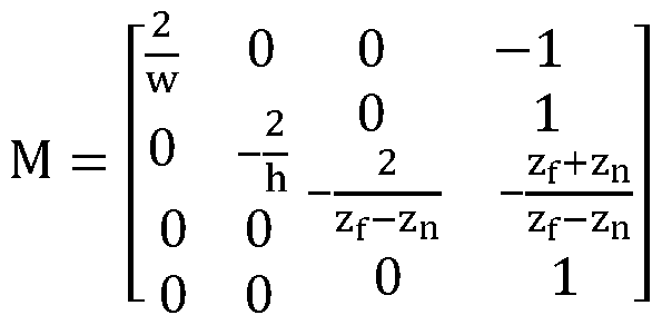
(2) and
a -cx 0
0 ,y 0
K =
0 0 zf + zn zf x zn
0 0 -1 0
(3) where w and h are the image's width and height, zn and zf are the near and far clipping planes, and the elements of K correspond to the standard pinhole camera model. Note that the negative values in K's third column are the result of inverting the z-axis to ensure proper OpenGL clipping.
[0056] For efficient handling of these generated textures, we render to an offscreen framebuffer that we then directly transfer into a CUDA buffer for processing using the CUDA-OpenGL interoperability. Sample synthetic views can be seen in Fig. 4.
[0057] B. Simplified Rotational Search
[0058] A naive approach to this local search problem would be to use the OpenGL pipeline to generate a synthetic view for each discrete step within the search volume, dom(x) x dom(y) x dom(0). However, this would result in generating nx x ny x ηθ synthetic views. Because the predicted view rasterization is the primary bottleneck of the system (taking nearly 1 ms for each render), here we propose an alternative method of pre-warping the camera measurement to explore the space (warpings can be performed at 0.1 ms instead and can be parallelized with the serial OpenGL rasterizations).
[0059] We can leverage the infinite homography, H∞ = KRK-1, and apply a bank of precomputed rotational mappings to the source image,
u'' = KRK-
(4) [0060] This technique allows us to use the OpenGL pipeline to generate only nx x ny synthetic views, first, then compare each against ηθ (warped) measurements. We still evaluate the same number of candidate pairs, though we significantly reduce our OpenGL pipeline overhead. A sample of these rotations can be seen in Fig. 5.
[0061] C. Normalized Mutual Information Image Registration
[0062] Mutual information has been successfully used in various fields for registering data from multi-modal sources. Mutual information provides a way to statistically measure the mutual dependence between two random variables, A and B. Most commonly, mutual information is defined in terms of the marginal and joint entropies of each:
MI(A, B) = H(A) + H(B) - H(A, B)
(5) where these entropies can be realized by evaluating the Shannon entropy over the random variables A and B:
H(A) = - ^ p(a) log p(a)
aeA
(6)
H(B) = - p(b) logp(b)
beB
(7)
, B) = - ^ ^ p(a, b) logp(a, b)
aeA beB
(8)
[0063] This mutual information formulation clearly demonstrates that maximization of mutual information is achieved through the minimization of the joint entropy of A and B. This optimality coincides with minimizing the dispersion of the two random variable's joint histogram.
[0064] By viewing the problem in this information theoretic way, we are able to capture more interdependency between random variables than with simple similarity or correlation-based measures. For example, tar strips in the road frequently appear dark in LIDAR reflectivity, yet bright in visual imagery. Correlative methods can only measure either a negative or positive correlation and often fails under varying illumination. However, because maximization of mutual information is concerned with seeking tightly compact joint distributions, we can successfully capture this mutual dependence (see Fig. 6B). Note that it would be quite difficult to create a hand-tuned feature detector that could identify this type of information for localization.
[0065] Because our source imagery and predicted views have varying amount of overlap (largely due to our pre-warping technique), we instead employ a normalized mutual information measure. The amount of overlap between two candidate images can bias the standard mutual information measure toward lower overlap image pairs. To avoid these effects, Studholme et al. proposed an overlap invariant measure of mutual information, normalized mutual information (NMI):
H(A) + H(B)
Ν Μ Ι(Α, Β) =
H(A, B)
(9)
This measure shares the same desirable qualities of the typical mutual information shown in (5), but is more robust to overlap changes.
[0066] In summary, our image registration amounts to the following optimization:
( >yk> e"i) = argmax N M I ( , Pk)
(10)
where Θ spans the pre-warping of source imagery, Cj, and (xkjk) explores the local search around our prior belief by generating synthetic views, Pk.
[0067] V. FILTERING FRAMEWORK
[0068] Our image registration is fairly agnostic to any particular filtering framework, so here we briefly present an Extended Kalman Filter (EKF) localization framework. Due to the near-planar surface model, we are able to treat localization as a 3-DOF optimization, with the state vector μιζ = {xk,yk< 9 }.
[0069] We define a discrete time process model and incorporate only image registration corrections into our state filter.
Predict Pk = Fk-il^k-i
Update Kk =∑kHT(Hk∑kHT + Rk)"1
μ¾ = j¾ + Kk(zk - hk(pk))
∑k = (I - KkHk)∑k(I - KkHk)T + KkRkKi
Here, Fk represents our plant model that integrates measurements from an Applanix IMU with uncertainty Qk_i, Hk is a linear observation model (identity matrix), and Kk is the corrective Kalman gain induced by our image registration measurement zk (with uncertainty Rk). The measurement zk is exactly the output of our image registration in (10) and Rk is estimated by fitting a covariance to the explored cost surface.
[0070] Our filter is initialized in a global frame from a single dual-antenna GPS measurement with high uncertainty, which provides a rough initial guess of global pose with orientation. We adaptively update our search bounds to ensure that we explore a 3-σ window around our posterior distribution. This dynamic approach allows us to perform an expensive, exhaustive search to initially align to our prior map while avoiding local maxima, then iteratively reduce the search space as our posterior confidence increases. We restrict the finest search resolution to be 20 cm over + 1 m. Note that aside from using GPS for
initializing the filter, this proposed localization method only uses input from inertial sensors, a wheel encoder, and a monocular camera.
[0071] VI. RESULTS
[0072] We evaluated our theory through data collected on our autonomous platform, a TORC ByWire XGV, as seen in Fig. 1 . This automated vehicle is equipped with four Velodyne HDL-32E 3D LIDAR scanners, a single Point Grey Flea3 monocular camera, and an Applanix POS-LV 420 inertial navigation system (INS).
[0073] Algorithms were implemented using OpenCV, OpenGL, and
CUDA and all experiments were run on a laptop equipped with a Core i7-3820QM central processing unit (CPU) and mid-range mobile GPU (NVIDIA Quadro K2000M).
[0074] In collecting each dataset, we made two passes through the same environment (on separate days) and aligned the two together using our offline SLAM procedure outlined in §lll. This allowed us to build a prior map ground-mesh on the first pass through the environment. Then, the subsequent pass would be well localized with respect to the ground-mesh, providing sufficiently accurate ground-truth in the experiment (accuracy an order or magnitude greater than our localization errors). Experiments are presented on two primary datasets:
[0075] · Downtown: 3.0 km trajectory through downtown Ann Arbor, Michigan in which multiple roads are traversed from both directions and the dataset contains several dynamic obstacles.
[0076] · Stadium: 1 .5 km trajectory around Michigan Stadium in Ann
Arbor, Michigan. This dataset presents a complicated environment for localization as half of the dataset is through a parking lot with infrequent lane markings.
[0077] A. Image Registration
[0078] Since our odometry source has significantly low drift-rates, image registration deficiencies can be masked by a well-tuned filtering
framework. Thus, we first look directly at the unfiltered image registration within the vicinity of ground-truth results.
[0079] To evaluate our image registration alone, we took our ground truth pose belief over the Downtown dataset and tried to perform an image registration to our map once a second. Ideally, we should be able to perfectly register our prior map, however, due to noise or insufficient visual variety in the environment, we end up with a distribution of lateral and longitudinal errors.
[0080] We present these results in two ways. First, we show our vehicle's trajectory through the prior map in which we color our longitudinal and lateral errors at each ground-truth pose, shown in Fig. 8. In this figure, larger and brighter markers indicate a larger error in registration at that point. One can immediately notice that we are not perfectly aligned longitudinally on long, straight stretches; during these stretches, the system frequently relies on a double, solid lane marking to localize off of. To maintain accuracy, the system requires occasional cross-streets, which provide more signal for constraining our pose belief.
[0081] Second, we show the same results in histogram form, as can be seen in Fig. 9, where we see that our registration is primarily concentrated within + 30 cm of our ground-truth. A common mode can be found in the tails of the histograms. This is caused by areas that are visually feature poor or obstructed by significant obstacles; for example, lane markings can often be perceived by the survey vehicle's LIDAR scanners and captured in our prior map, yet the subtle transition between pavement and faded lane markings cannot be observed by our camera. In these scenarios, the optimal normalized mutual information will try to pull the registration toward the edges of our prior map— the edges are often feature poor as well, and this alignment minimizes the joint entropy of the two signals.
[0082] Finally, we present several scenarios of our image registration succeeding (Fig. 6) and common causes of failure (Fig. 7). These figures were generated by exploring within a local window around known ground truth.
[0083] B. Filtered Localization
[0084] We next looked at filtered response of our system that incorporates the projective image registration into an EKF localization framework. Moreover, we compare our localization performance against our own implementation of the state-of-the-art LIDAR-based localization proposed by Levinson et al. Our LIDAR-based localizer builds orthographic ground images using the four Velodyne HDL-32E's onboard; these orthographic ground images can then be aligned to an orthographic prior map built using an accumulation of these scans.
[0085] We present longitudinal and lateral errors over time for GPS, LIDAR-based localization, and our proposed single camera algorithm within the Downtown and Stadium datasets (see Fig. 10). Our proposed solution is able to maintain error levels at a similar order of magnitude as the LIDAR-based options, while using a sensor that is several orders of magnitude cheaper.
[0086] Note that the Stadium results show a rather large variance in longitudinal error; this is because half of the dataset is through a parking lot containing little visual variation. Also, we are slow to initially converge longitudinally because the first 20 s of the run is on a two-lane road containing only a double, solid lane marker.
[0087] These results are also summarized in Table I. Here we show that we are able to achieve longitudinal and lateral root mean square (RMS) errors of 19.1 cm and 14.3 cm, respectively, on the Downtown dataset. Further, we obtain longitudinal and lateral RMS errors of 45.4 cm and 20.5 cm, respectively, on the Stadium dataset.
Downtown RMS Error Stadium RMS Error
Method Longitudinal Lateral Longitudinal Lateral
GPS 91 .0 cm 100.5 cm 81 .7 cm 73.4 cm
LIDAR-based 12.4 cm 8.0 cm 14.3 cm 10.9 cm
Proposed 19.1 cm 14.3 cm 45.4 cm 20.5 cm
TABLE 1 : Comparison of RMS errors for GPS, LIDAR-based localization, and our proposed vision-only localization. Our method is able to maintain sufficiently well localized for use in an automated vehicle.
[0088] VII. CONCLUSION
[0089] In this patent disclosure, we showed that a single monocular camera can be used as an information source for visual localization in a 3D LIDAR map containing surface reflectivities. By maximizing normalized mutual information, we are able to register a video stream to our prior map. Our system is aided by a GPU implementation, leveraging OpenGL to generate synthetic views of the environment; this implementation is able to provide corrective positional updates at -10 Hz. Moreover, we compared our algorithm against the state-of-the-art LIDAR-only automated vehicle localization, revealing that the present teachings can achieve a similar order of magnitude error rate, with a sensor that is several orders of magnitude cheaper.
[0090] The foregoing description of the embodiments has been provided for purposes of illustration and description. It is not intended to be exhaustive or to limit the disclosure. Individual elements or features of a particular embodiment are generally not limited to that particular embodiment, but, where applicable, are interchangeable and can be used in a selected embodiment, even if not specifically shown or described. The same may also be varied in many ways. Such variations are not to be regarded as a departure from the disclosure, and all such modifications are intended to be included within the scope of the disclosure.
Claims
1 . A method of visual localization using a visual camera system, the method comprising:
outputting real-time visual camera data from a visual camera system; accessing a database of LIDAR-generated prior map information and generating a synthetic image;
comparing the synthetic image to the real-time visual camera data to determine corrected position data to determine a camera position based on the corrected position data; and
applying corrected navigation information of the camera based on the determined camera position.
2. The method according to Claim 1 wherein the visual camera system is a monocular camera system.
3. The method according to Claim 1 wherein the LIDAR-generated prior map information is three-dimensional map information.
4. The method according to Claim 1 wherein the LIDAR-generated prior map information comprises odometry and global positioning system prior constraints.
5. The method according to Claim 1 wherein the LIDAR-generated prior map information is constrained to produce a near-planar graph.
6. The method according to Claim 1 , further comprising:
producing the LIDAR-generated prior map information by extracting a ground-plane at each pose and draping an orthographic texture over a varying z- height map.
7. The method according to Claim 1 wherein the step of comparing the synthetic image to the real-time visual camera data to determine corrected position data to determine a camera position based on the corrected position data comprises:
determining a relative offset; and
aligning the LIDAR-generated prior map to the visual camera data.
8. The method according to Claim 1 further comprising:
receiving the real-time visual camera data via a graphics processing unit, said graphics processing unit performing the step of accessing a database of LIDAR-generated prior map information and generating a synthetic image.
Priority Applications (1)
| Application Number | Priority Date | Filing Date | Title |
|---|---|---|---|
| EP16740584.4A EP3248029A4 (en) | 2015-01-19 | 2016-01-19 | Visual localization within lidar maps |
Applications Claiming Priority (4)
| Application Number | Priority Date | Filing Date | Title |
|---|---|---|---|
| US201562104915P | 2015-01-19 | 2015-01-19 | |
| US62/104,915 | 2015-01-19 | ||
| US15/000,169 | 2016-01-19 | ||
| US15/000,169 US9989969B2 (en) | 2015-01-19 | 2016-01-19 | Visual localization within LIDAR maps |
Publications (1)
| Publication Number | Publication Date |
|---|---|
| WO2016118499A1 true WO2016118499A1 (en) | 2016-07-28 |
Family
ID=56407836
Family Applications (1)
| Application Number | Title | Priority Date | Filing Date |
|---|---|---|---|
| PCT/US2016/013896 WO2016118499A1 (en) | 2015-01-19 | 2016-01-19 | Visual localization within lidar maps |
Country Status (3)
| Country | Link |
|---|---|
| US (1) | US9989969B2 (en) |
| EP (1) | EP3248029A4 (en) |
| WO (1) | WO2016118499A1 (en) |
Cited By (3)
| Publication number | Priority date | Publication date | Assignee | Title |
|---|---|---|---|---|
| WO2019169348A1 (en) * | 2018-03-02 | 2019-09-06 | DeepMap Inc. | Visualization of high definition map data |
| EP3893074A1 (en) | 2020-04-06 | 2021-10-13 | General Electric Company | Localization method for mobile remote inspection and/or manipulation tools in confined spaces and associated system |
| FR3117253A1 (en) * | 2020-12-03 | 2022-06-10 | Psa Automobiles Sa | Method and device for transmitting guidance elements by a first vehicle |
Families Citing this family (69)
| Publication number | Priority date | Publication date | Assignee | Title |
|---|---|---|---|---|
| US11370422B2 (en) * | 2015-02-12 | 2022-06-28 | Honda Research Institute Europe Gmbh | Method and system in a vehicle for improving prediction results of an advantageous driver assistant system |
| DE102016214868A1 (en) * | 2016-08-10 | 2018-02-15 | Volkswagen Aktiengesellschaft | Method and device for creating or supplementing a map for a motor vehicle |
| KR102406502B1 (en) * | 2016-12-14 | 2022-06-10 | 현대자동차주식회사 | Apparatus and method for controlling narrow road driving of vehicle |
| DE102016225595A1 (en) * | 2016-12-20 | 2018-06-21 | Siemens Aktiengesellschaft | Method and arrangement for calibrating at least one sensor of a rail vehicle |
| US10078790B2 (en) | 2017-02-16 | 2018-09-18 | Honda Motor Co., Ltd. | Systems for generating parking maps and methods thereof |
| US10430968B2 (en) | 2017-03-14 | 2019-10-01 | Ford Global Technologies, Llc | Vehicle localization using cameras |
| JP6870604B2 (en) * | 2017-03-16 | 2021-05-12 | 株式会社デンソー | Self-position estimator |
| US11175146B2 (en) * | 2017-05-11 | 2021-11-16 | Anantak Robotics Inc. | Autonomously moving machine and method for operating an autonomously moving machine |
| CN107084716A (en) * | 2017-05-16 | 2017-08-22 | 苏州艾吉威机器人有限公司 | A kind of localization method of the areflexia plate laser navigation of use adminicle |
| US10282860B2 (en) * | 2017-05-22 | 2019-05-07 | Honda Motor Co., Ltd. | Monocular localization in urban environments using road markings |
| US10866101B2 (en) | 2017-06-13 | 2020-12-15 | Tusimple, Inc. | Sensor calibration and time system for ground truth static scene sparse flow generation |
| US20180356831A1 (en) * | 2017-06-13 | 2018-12-13 | TuSimple | Sparse image point correspondences generation and correspondences refinement method for ground truth static scene sparse flow generation |
| US10360686B2 (en) * | 2017-06-13 | 2019-07-23 | TuSimple | Sparse image point correspondences generation and correspondences refinement system for ground truth static scene sparse flow generation |
| US11367354B2 (en) * | 2017-06-22 | 2022-06-21 | Apollo Intelligent Driving Technology (Beijing) Co., Ltd. | Traffic prediction based on map images for autonomous driving |
| US10579067B2 (en) * | 2017-07-20 | 2020-03-03 | Huawei Technologies Co., Ltd. | Method and system for vehicle localization |
| US10565457B2 (en) | 2017-08-23 | 2020-02-18 | Tusimple, Inc. | Feature matching and correspondence refinement and 3D submap position refinement system and method for centimeter precision localization using camera-based submap and LiDAR-based global map |
| US10762673B2 (en) | 2017-08-23 | 2020-09-01 | Tusimple, Inc. | 3D submap reconstruction system and method for centimeter precision localization using camera-based submap and LiDAR-based global map |
| US10223806B1 (en) * | 2017-08-23 | 2019-03-05 | TuSimple | System and method for centimeter precision localization using camera-based submap and LiDAR-based global map |
| DE112017007967T5 (en) | 2017-08-28 | 2020-06-10 | Intel Corporation | POSITION ESTIMATION FOR MOBILE AUTONOMOUS DEVICE IN PART PERIODS OF A FULL SENSOR SCAN |
| AU2018326401C1 (en) | 2017-09-04 | 2023-07-13 | Commonwealth Scientific And Industrial Research Organisation | Method and system for use in performing localisation |
| CN111492403A (en) | 2017-10-19 | 2020-08-04 | 迪普迈普有限公司 | Lidar to camera calibration for generating high definition maps |
| US10635116B2 (en) | 2017-10-19 | 2020-04-28 | Ford Global Technologies, Llc | Video calibration with illumination invariant image |
| CN107909608A (en) * | 2017-10-30 | 2018-04-13 | 北京航天福道高技术股份有限公司 | The moving target localization method and device suppressed based on mutual information and local spectrum |
| CN109840448A (en) * | 2017-11-24 | 2019-06-04 | 百度在线网络技术(北京)有限公司 | Information output method and device for automatic driving vehicle |
| CN108121347B (en) * | 2017-12-29 | 2020-04-07 | 北京三快在线科技有限公司 | Method and device for controlling movement of equipment and electronic equipment |
| CN108364014A (en) * | 2018-01-08 | 2018-08-03 | 东南大学 | A kind of multi-sources Information Fusion Method based on factor graph |
| US10739459B2 (en) | 2018-01-12 | 2020-08-11 | Ford Global Technologies, Llc | LIDAR localization |
| WO2019169358A1 (en) | 2018-03-02 | 2019-09-06 | DeepMap Inc. | Camera based localization for autonomous vehicles |
| US10445913B2 (en) * | 2018-03-05 | 2019-10-15 | Faro Technologies, Inc. | System and method of scanning and editing two dimensional floorplans |
| US10830871B2 (en) * | 2018-03-21 | 2020-11-10 | Zoox, Inc. | Sensor calibration |
| CN112292582A (en) * | 2018-04-20 | 2021-01-29 | 文远知行有限公司 | Method and system for generating high definition map |
| US11035933B2 (en) | 2018-05-04 | 2021-06-15 | Honda Motor Co., Ltd. | Transition map between lidar and high-definition map |
| US11188089B2 (en) | 2018-06-21 | 2021-11-30 | Ford Global Technologies, Llc | Localization for autonomous vehicles using gaussian mixture models |
| US11015940B2 (en) | 2018-07-13 | 2021-05-25 | Toyota Motor Engineering & Manufacturing North America, Inc. | Systems and methods for longitudinal position correction of a vehicle using mapped landmarks |
| CN108846867A (en) * | 2018-08-29 | 2018-11-20 | 安徽云能天智能科技有限责任公司 | A kind of SLAM system based on more mesh panorama inertial navigations |
| US10955857B2 (en) | 2018-10-02 | 2021-03-23 | Ford Global Technologies, Llc | Stationary camera localization |
| US10962984B2 (en) | 2018-11-20 | 2021-03-30 | Toyota Research Institute, Inc. | Sensor-agnostic detection using high-level feature extraction |
| US11127162B2 (en) | 2018-11-26 | 2021-09-21 | Ford Global Technologies, Llc | Method and apparatus for improved location decisions based on surroundings |
| US10704918B2 (en) | 2018-11-26 | 2020-07-07 | Ford Global Technologies, Llc | Method and apparatus for improved location decisions based on surroundings |
| US11175156B2 (en) | 2018-12-12 | 2021-11-16 | Ford Global Technologies, Llc | Method and apparatus for improved location decisions based on surroundings |
| CN113661505A (en) | 2019-02-19 | 2021-11-16 | 克朗设备公司 | System and method for calibrating attitude of sensor associated with materials handling vehicle |
| US11430206B1 (en) * | 2019-04-16 | 2022-08-30 | Apple Inc. | Branch-and-bound search algorithm for 4D camera localization |
| DE102019206036A1 (en) | 2019-04-26 | 2020-10-29 | Volkswagen Aktiengesellschaft | Method and device for determining the geographical position and orientation of a vehicle |
| US11960297B2 (en) * | 2019-05-03 | 2024-04-16 | Lg Electronics Inc. | Robot generating map based on multi sensors and artificial intelligence and moving based on map |
| KR20210155833A (en) * | 2019-05-16 | 2021-12-24 | 엘지전자 주식회사 | A method to create a map based on multiple sensors and artificial intelligence, establish correlation between nodes, and create a robot and map that travel using the map |
| KR102220564B1 (en) * | 2019-05-30 | 2021-02-25 | 엘지전자 주식회사 | A method for estimating a location using multi-sensors and a robot implementing the same |
| KR102246236B1 (en) * | 2019-06-14 | 2021-04-28 | 엘지전자 주식회사 | How to update a map in Fusion Slam and a robot that implements it |
| CN110414418B (en) * | 2019-07-25 | 2022-06-03 | 电子科技大学 | Road detection method for multi-scale fusion of image-laser radar image data |
| US11556000B1 (en) | 2019-08-22 | 2023-01-17 | Red Creamery Llc | Distally-actuated scanning mirror |
| US20210095980A1 (en) * | 2019-09-30 | 2021-04-01 | Gm Cruise Holdings Llc | Enhanced localization |
| US10969232B1 (en) | 2019-12-06 | 2021-04-06 | Ushr Inc. | Alignment of standard-definition and High-Definition maps |
| US11315266B2 (en) * | 2019-12-16 | 2022-04-26 | Robert Bosch Gmbh | Self-supervised depth estimation method and system |
| US11288522B2 (en) | 2019-12-31 | 2022-03-29 | Woven Planet North America, Inc. | Generating training data from overhead view images |
| US11037328B1 (en) * | 2019-12-31 | 2021-06-15 | Lyft, Inc. | Overhead view image generation |
| US11244500B2 (en) | 2019-12-31 | 2022-02-08 | Woven Planet North America, Inc. | Map feature extraction using overhead view images |
| US11320272B2 (en) * | 2020-07-07 | 2022-05-03 | Waymo Llc | Localization adaptation based on weather estimation |
| CN112034706B (en) * | 2020-08-17 | 2021-07-27 | 华中科技大学 | Mobile robot fault-tolerant control method and equipment based on multi-mode switching |
| CN114200481A (en) * | 2020-08-28 | 2022-03-18 | 华为技术有限公司 | Positioning method, positioning system and vehicle |
| CN112328715B (en) * | 2020-10-16 | 2022-06-03 | 浙江商汤科技开发有限公司 | Visual positioning method, training method of related model, related device and equipment |
| TWI768548B (en) * | 2020-11-19 | 2022-06-21 | 財團法人資訊工業策進會 | System and method for generating basic information for positioning and self-positioning determination device |
| CN112489091B (en) * | 2020-12-18 | 2022-08-12 | 湖南华南光电(集团)有限责任公司 | Full strapdown image seeker target tracking method based on direct-aiming template |
| US11508089B2 (en) * | 2021-03-05 | 2022-11-22 | Black Sesame Technologies Inc. | LiDAR assisted wheel encoder to camera calibration |
| CN113190002B (en) * | 2021-04-25 | 2022-09-30 | 上海工程技术大学 | Method for realizing automatic inspection by high-speed rail box girder inspection robot |
| US20220358671A1 (en) * | 2021-05-07 | 2022-11-10 | Tencent America LLC | Methods of estimating pose graph and transformation matrix between cameras by recognizing markers on the ground in panorama images |
| CN113340295B (en) * | 2021-06-16 | 2021-12-21 | 广东工业大学 | Unmanned ship near-shore real-time positioning and mapping method with multiple ranging sensors |
| US20230126833A1 (en) * | 2021-10-21 | 2023-04-27 | Argo AI, LLC | System and method for simultaneous online lidar intensity calibration and road marking change detection |
| WO2023212575A1 (en) * | 2022-04-25 | 2023-11-02 | Virginia Tech Intellectual Properties, Inc. | Automated objects labeling in video data for machine learning and other classifiers |
| CN114719843B (en) * | 2022-06-09 | 2022-09-30 | 长沙金维信息技术有限公司 | High-precision positioning method in complex environment |
| US20230400306A1 (en) * | 2022-06-14 | 2023-12-14 | Volvo Car Corporation | Localization for autonomous movement using vehicle sensors |
Citations (4)
| Publication number | Priority date | Publication date | Assignee | Title |
|---|---|---|---|---|
| US20050190972A1 (en) * | 2004-02-11 | 2005-09-01 | Thomas Graham A. | System and method for position determination |
| US20080312824A1 (en) * | 2005-06-14 | 2008-12-18 | Mun Ho Jung | Matching camera-photographed image with map data in portable terminal and travel route guidance method |
| US20140022262A1 (en) * | 2012-07-19 | 2014-01-23 | Honeywell International Inc. | Method of correlating images with terrain elevation maps for navigation |
| US20140098107A1 (en) * | 2010-02-04 | 2014-04-10 | Microsoft Corporation | Transitioning Between Top-Down Maps and Local Navigation of Reconstructed 3-D Scenes |
Family Cites Families (22)
| Publication number | Priority date | Publication date | Assignee | Title |
|---|---|---|---|---|
| US7006881B1 (en) | 1991-12-23 | 2006-02-28 | Steven Hoffberg | Media recording device with remote graphic user interface |
| US7418346B2 (en) | 1997-10-22 | 2008-08-26 | Intelligent Technologies International, Inc. | Collision avoidance methods and systems |
| US7162338B2 (en) | 2002-12-17 | 2007-01-09 | Evolution Robotics, Inc. | Systems and methods for computing a relative pose for global localization in a visual simultaneous localization and mapping system |
| US7363157B1 (en) * | 2005-02-10 | 2008-04-22 | Sarnoff Corporation | Method and apparatus for performing wide area terrain mapping |
| US7570783B2 (en) | 2005-07-01 | 2009-08-04 | Deere & Company | Method and system for vehicular guidance using a crop image |
| US20080033645A1 (en) | 2006-08-03 | 2008-02-07 | Jesse Sol Levinson | Pobabilistic methods for mapping and localization in arbitrary outdoor environments |
| KR100926783B1 (en) | 2008-02-15 | 2009-11-13 | 한국과학기술연구원 | Method for self-localization of a robot based on object recognition and environment information around the recognized object |
| US8126642B2 (en) | 2008-10-24 | 2012-02-28 | Gray & Company, Inc. | Control and systems for autonomously driven vehicles |
| US8364334B2 (en) | 2008-10-30 | 2013-01-29 | Honeywell International Inc. | System and method for navigating an autonomous vehicle using laser detection and ranging |
| US8301374B2 (en) | 2009-08-25 | 2012-10-30 | Southwest Research Institute | Position estimation for ground vehicle navigation based on landmark identification/yaw rate and perception of landmarks |
| US8318012B2 (en) | 2010-06-04 | 2012-11-27 | Gulp Oil Skimmers, L.L.C. | Barge oil skimmer |
| US8704887B2 (en) * | 2010-12-02 | 2014-04-22 | GM Global Technology Operations LLC | Multi-object appearance-enhanced fusion of camera and range sensor data |
| US8711206B2 (en) | 2011-01-31 | 2014-04-29 | Microsoft Corporation | Mobile camera localization using depth maps |
| WO2012142587A1 (en) * | 2011-04-15 | 2012-10-18 | Irobot Corporation | Method for path generation for an end effector of a robot |
| US20120300020A1 (en) | 2011-05-27 | 2012-11-29 | Qualcomm Incorporated | Real-time self-localization from panoramic images |
| GB201116958D0 (en) | 2011-09-30 | 2011-11-16 | Bae Systems Plc | Use of synthetic overhead images for vehicle localisation |
| KR101703144B1 (en) | 2012-02-09 | 2017-02-06 | 한국전자통신연구원 | Apparatus and method for autonomous driving |
| US8612135B1 (en) | 2012-02-14 | 2013-12-17 | Google Inc. | Method and apparatus to localize an autonomous vehicle using convolution |
| GB2501466A (en) | 2012-04-02 | 2013-10-30 | Univ Oxford | Localising transportable apparatus |
| US8798357B2 (en) | 2012-07-09 | 2014-08-05 | Microsoft Corporation | Image-based localization |
| US8473144B1 (en) | 2012-10-30 | 2013-06-25 | Google Inc. | Controlling vehicle lateral lane positioning |
| US9251590B2 (en) | 2013-01-24 | 2016-02-02 | Microsoft Technology Licensing, Llc | Camera pose estimation for 3D reconstruction |
-
2016
- 2016-01-19 US US15/000,169 patent/US9989969B2/en active Active
- 2016-01-19 WO PCT/US2016/013896 patent/WO2016118499A1/en active Application Filing
- 2016-01-19 EP EP16740584.4A patent/EP3248029A4/en not_active Withdrawn
Patent Citations (4)
| Publication number | Priority date | Publication date | Assignee | Title |
|---|---|---|---|---|
| US20050190972A1 (en) * | 2004-02-11 | 2005-09-01 | Thomas Graham A. | System and method for position determination |
| US20080312824A1 (en) * | 2005-06-14 | 2008-12-18 | Mun Ho Jung | Matching camera-photographed image with map data in portable terminal and travel route guidance method |
| US20140098107A1 (en) * | 2010-02-04 | 2014-04-10 | Microsoft Corporation | Transitioning Between Top-Down Maps and Local Navigation of Reconstructed 3-D Scenes |
| US20140022262A1 (en) * | 2012-07-19 | 2014-01-23 | Honeywell International Inc. | Method of correlating images with terrain elevation maps for navigation |
Non-Patent Citations (2)
| Title |
|---|
| R. W. WOLCOTT ET AL.: "Visual localization within LIDAR maps for automated u rban driving", INTELLIGENT ROBOTS AND SYSTEMS (IROS 2014), 2014 IEEE /RSJ INTERNATIONAL CONFERENCE ON., 14 September 2014 (2014-09-14), pages 176 - 183, XP032676885 * |
| See also references of EP3248029A4 * |
Cited By (6)
| Publication number | Priority date | Publication date | Assignee | Title |
|---|---|---|---|---|
| WO2019169348A1 (en) * | 2018-03-02 | 2019-09-06 | DeepMap Inc. | Visualization of high definition map data |
| US11365976B2 (en) | 2018-03-02 | 2022-06-21 | Nvidia Corporation | Semantic label based filtering of objects in an image generated from high definition map data |
| US11566903B2 (en) | 2018-03-02 | 2023-01-31 | Nvidia Corporation | Visualization of high definition map data |
| EP3893074A1 (en) | 2020-04-06 | 2021-10-13 | General Electric Company | Localization method for mobile remote inspection and/or manipulation tools in confined spaces and associated system |
| US11579097B2 (en) | 2020-04-06 | 2023-02-14 | Baker Hughes Holdings Llc | Localization method and system for mobile remote inspection and/or manipulation tools in confined spaces |
| FR3117253A1 (en) * | 2020-12-03 | 2022-06-10 | Psa Automobiles Sa | Method and device for transmitting guidance elements by a first vehicle |
Also Published As
| Publication number | Publication date |
|---|---|
| US20160209846A1 (en) | 2016-07-21 |
| EP3248029A4 (en) | 2018-10-03 |
| US9989969B2 (en) | 2018-06-05 |
| EP3248029A1 (en) | 2017-11-29 |
Similar Documents
| Publication | Publication Date | Title |
|---|---|---|
| US9989969B2 (en) | Visual localization within LIDAR maps | |
| Wolcott et al. | Visual localization within lidar maps for automated urban driving | |
| Heng et al. | Project autovision: Localization and 3d scene perception for an autonomous vehicle with a multi-camera system | |
| EP2660777B1 (en) | Image registration of multimodal data using 3D geoarcs | |
| Senlet et al. | A framework for global vehicle localization using stereo images and satellite and road maps | |
| Meilland et al. | A spherical robot-centered representation for urban navigation | |
| Senlet et al. | Satellite image based precise robot localization on sidewalks | |
| WO2013045935A1 (en) | Localising a vehicle along a route | |
| Dawood et al. | Harris, SIFT and SURF features comparison for vehicle localization based on virtual 3D model and camera | |
| Nagy et al. | Online targetless end-to-end camera-LiDAR self-calibration | |
| Hu et al. | Accurate global trajectory alignment using poles and road markings | |
| Tao et al. | Automated processing of mobile mapping image sequences | |
| Zhu et al. | Fusing GNSS/INS/vision with a priori feature map for high-precision and continuous navigation | |
| Khoshelham et al. | Vehicle positioning in the absence of GNSS signals: Potential of visual-inertial odometry | |
| Shi et al. | Fusion of a panoramic camera and 2D laser scanner data for constrained bundle adjustment in GPS-denied environments | |
| Hoang et al. | Combining edge and one-point ransac algorithm to estimate visual odometry | |
| Jende et al. | Fully automatic feature-based registration of mobile mapping and aerial nadir images for enabling the adjustment of mobile platform locations in GNSS-denied urban environments | |
| Jende et al. | Low-level tie feature extraction of mobile mapping data (mls/images) and aerial imagery | |
| Fanta‐Jende et al. | Co‐registration of panoramic mobile mapping images and oblique aerial images | |
| Jonas et al. | IMAGO: Image-guided navigation for visually impaired people | |
| Park et al. | Localization of an unmanned ground vehicle based on hybrid 3D registration of 360 degree range data and DSM | |
| Velasco-Sánchez et al. | LiLO: Lightweight and low-bias LiDAR Odometry method based on spherical range image filtering | |
| Park et al. | Localization of an unmanned ground vehicle using 3D registration of laser range data and DSM | |
| Gakne et al. | Skyline-based positioning in urban canyons using a narrow fov upward-facing camera | |
| Leung et al. | Cost-effective Camera Localization Aided by Prior Point Clouds Maps for Level 3 Autonomous Driving Vehicles |
Legal Events
| Date | Code | Title | Description |
|---|---|---|---|
| 121 | Ep: the epo has been informed by wipo that ep was designated in this application |
Ref document number: 16740584 Country of ref document: EP Kind code of ref document: A1 |
|
| NENP | Non-entry into the national phase |
Ref country code: DE |
|
| REEP | Request for entry into the european phase |
Ref document number: 2016740584 Country of ref document: EP |