WO2016102089A1 - Hermetic compressor with heat pipe - Google Patents
Hermetic compressor with heat pipe Download PDFInfo
- Publication number
- WO2016102089A1 WO2016102089A1 PCT/EP2015/072535 EP2015072535W WO2016102089A1 WO 2016102089 A1 WO2016102089 A1 WO 2016102089A1 EP 2015072535 W EP2015072535 W EP 2015072535W WO 2016102089 A1 WO2016102089 A1 WO 2016102089A1
- Authority
- WO
- WIPO (PCT)
- Prior art keywords
- compressor
- stator
- heat
- intermediate member
- casing
- Prior art date
- Legal status (The legal status is an assumption and is not a legal conclusion. Google has not performed a legal analysis and makes no representation as to the accuracy of the status listed.)
- Ceased
Links
Images




Classifications
-
- F—MECHANICAL ENGINEERING; LIGHTING; HEATING; WEAPONS; BLASTING
- F04—POSITIVE - DISPLACEMENT MACHINES FOR LIQUIDS; PUMPS FOR LIQUIDS OR ELASTIC FLUIDS
- F04B—POSITIVE-DISPLACEMENT MACHINES FOR LIQUIDS; PUMPS
- F04B35/00—Piston pumps specially adapted for elastic fluids and characterised by the driving means to their working members, or by combination with, or adaptation to, specific driving engines or motors, not otherwise provided for
- F04B35/04—Piston pumps specially adapted for elastic fluids and characterised by the driving means to their working members, or by combination with, or adaptation to, specific driving engines or motors, not otherwise provided for the means being electric
-
- H—ELECTRICITY
- H02—GENERATION; CONVERSION OR DISTRIBUTION OF ELECTRIC POWER
- H02K—DYNAMO-ELECTRIC MACHINES
- H02K9/00—Arrangements for cooling or ventilating
- H02K9/22—Arrangements for cooling or ventilating by solid heat conducting material embedded in, or arranged in contact with, the stator or rotor, e.g. heat bridges
- H02K9/225—Heat pipes
-
- F—MECHANICAL ENGINEERING; LIGHTING; HEATING; WEAPONS; BLASTING
- F04—POSITIVE - DISPLACEMENT MACHINES FOR LIQUIDS; PUMPS FOR LIQUIDS OR ELASTIC FLUIDS
- F04B—POSITIVE-DISPLACEMENT MACHINES FOR LIQUIDS; PUMPS
- F04B39/00—Component parts, details, or accessories, of pumps or pumping systems specially adapted for elastic fluids, not otherwise provided for in, or of interest apart from, groups F04B25/00 - F04B37/00
- F04B39/06—Cooling; Heating; Prevention of freezing
-
- F—MECHANICAL ENGINEERING; LIGHTING; HEATING; WEAPONS; BLASTING
- F28—HEAT EXCHANGE IN GENERAL
- F28D—HEAT-EXCHANGE APPARATUS, NOT PROVIDED FOR IN ANOTHER SUBCLASS, IN WHICH THE HEAT-EXCHANGE MEDIA DO NOT COME INTO DIRECT CONTACT
- F28D15/00—Heat-exchange apparatus with the intermediate heat-transfer medium in closed tubes passing into or through the conduit walls ; Heat-exchange apparatus employing intermediate heat-transfer medium or bodies
- F28D15/02—Heat-exchange apparatus with the intermediate heat-transfer medium in closed tubes passing into or through the conduit walls ; Heat-exchange apparatus employing intermediate heat-transfer medium or bodies in which the medium condenses and evaporates, e.g. heat pipes
- F28D15/0275—Arrangements for coupling heat-pipes together or with other structures, e.g. with base blocks; Heat pipe cores
Definitions
- the present invention relates to a hermetic compressor, the performance of which is increased by cooling the electric motor.
- the electric motor that is used for driving the crankshaft-piston rod, cylinder-piston mechanism and crankshaft-piston mechanism are situated in a leak-proof casing.
- the loss occurring due to the motor efficiency being 70-80% and the mechanical losses occurring at the bearings cause the components in the compressor to heat up and cause the temperature of the refrigerant to increase before entering the cylinder, thus decreasing volumetric efficiency.
- the increase in the temperature of the refrigerant during the compression process in the cylinder also causes heat transfer from the cylinder region into the casing. Since the compressor input power increases in cases wherein the cylinder is not cooled efficiently, performance decreases.
- the entire thermal energy generated due to mechanical losses and the compression process is transferred to the environment via the casing when the steady state is reached.
- the increase in the temperatures of the electric motor and other components decreases the volumetric efficiency since the density of the refrigerant received into the cylinder is decreased, while increasing the work load required during the compression since the temperature of the cylinder increases.
- cooling the electric motor plays a significant role in the performance of the compressor.
- the evaporator end of the heat pipe is placed into a hole bored on the cylinder and the condenser end thereof extends out of the casing.
- the evaporator end of the heat pipe is immersed in to the lubricant while the condenser end is outside the casing.
- the aim of the present invention is the realization of a compressor wherein the compressor motor is cooled so as to increase the performance of the compressor and to decrease the energy consumption thereof.
- heat pipes are used, that have a heat absorbing end and a heat dissipating end, or as they are known in the state of the art, an evaporator region and a condenser region.
- the heat absorbing end of the heat pipe is mounted onto the stator of the motor while the heat dissipating end thereof extends towards the casing.
- the heat pipe enables the heat of the stator, thus of the motor, to be discharged out of the casing.
- the efficiency of the compressor is enabled to be increased by decreasing the temperature of the electric motor reaching high temperatures in the compressor.
- the refrigerant fluid that is in the liquid phase at the evaporator region, changes into the gas phase by drawing heat from the electric motor and draws the heat required for meeting the evaporation latent heat from the high temperature stator, thus enabling the temperature of the high temperature motor lamination sheets inside the compressor, thus the temperature of the motor, to be decreased. Since the cooling of the electric motor will decrease the heat transfer to the body bearing the movable components in the compressor, this situation also enables the volumetric efficiency and the motor efficiency to increase.
- the present invention since the temperature of the motor, that is one of the most important heat sources in the compressor, is decreased, the increase in the temperature of the lubricant is limited. Thus, the lubrication feature of the compressor is improved.
- the heat pipe is mounted onto the stator by means of an intermediate member.
- the heat pipes are enabled to be fixed onto the stator without making any changes on the laminations.
- springs are disposed between the stator and the intermediate member whereon the heat pipe is mounted.
- the heat pipe is enabled to be affected by the vibrations generated due to the operation of the compressor at minimum.
- the intermediate members while being mounted onto the stator, are fixed to each other by means of connection members.
- connection members comprise recesses and protrusions that are oppositely provided on the adjacent edges of the intermediate members.
- connection members comprise the recesses oppositely provided on the adjacent edges of the intermediate member and the springs that connect these recesses to each other.
- connection member comprises the protrusions oppositely provided on the adjacent edges of the intermediate members and the springs that connect these protrusions to each other.
- the intermediate members are fixed onto the stator so as to be affected by the vibrations generated due to the operation of the motor at minimum.
- the stator laminations of the electric motor are enabled to be cooled.
- the gas temperature inside the compressor is decreased, thus the volumetric efficiency is increased.
- the COP of the compressor is increased to enable the latter to be operated in a more efficient manner, thereby decreasing the energy consumption of the refrigerator.
- the compressor lubricant temperature is decreased and the bearings are enabled to be lubricated more efficiently, thus decreasing mechanical losses and minimizing abrasion risks.
- the heat pipe is enabled to be affected from the compressor vibrations at minimum.
- Figure 1 – is the schematic view of a compressor.
- Figure 2 – is the exploded view of a compressor.
- Figure 3 — is the top view of the casing of a compressor and the body disposed therein.
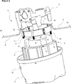
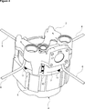
- Figure 4 – is the detailed view of the stator, the body, the heat pipe and the intermediate member.
- Figure 5 — is the detailed view of the segmented intermediate members and the connection members joining the intermediate members.
- Figure 6 — is the detailed view of the connection members in another embodiment of the present invention.
- Figure 7 — is the detailed view of the connection members in yet another embodiment of the present invention.
- the hermetic compressor (1) comprises a body (2) wherein the crankshaft-piston rod and cylinder-piston mechanisms (M) are borne; a crankshaft (16) that rotates in the body (2); a motor (4) that provides the rotation of the crankshaft (16) and that has a ring-shaped core, a doughnut-shaped stator (5) composed of copper wire windings (S) arranged on the core and furthermore a rotor (17) that is passed through the gap at the center of the stator (5) to be mounted to the crankshaft (16) and that rotates inside the stator (5); and a casing (3) wherein the body (2) and the motor (4) are placed.
- the compressor (1) of the present invention comprises one or more than one heat pipe (6) that has a heat absorbing end (18) mounted onto the stator (5) and a heat dissipating end (19) extending towards the casing (3) ( Figure 1, Figure 2, Figure 3 and Figure 4).
- the refrigerant fluid that is in the liquid phase at the heat absorbing end (18) (evaporator region) in the heat pipe (6) changes into the gas phase by drawing heat from the stator (5), thus from the motor (4).
- the heat required for meeting the evaporation latent heat is drawing from the high temperature stator (5).
- the temperature of the high temperature stator (5) inside the compressor, thus of the motor (4) is decreased. Since the cooling of the motor (4) will decrease the heat transfer to the body (2), the volumetric efficiency is enabled to be increased. Moreover, the decrease in the motor (4) temperature enables the efficiency of the motor (4) to be increased.
- the heat absorbing end (18) of the heat pump (6) mounted onto the stator (5) is U-shaped and bent like a hook while the heat dissipating end (19) is flat.
- the stator (5) core is composed of stacked laminations and the heat absorbing end (18) of the heat pipe (6) is mounted to the last lamination at the upper or lower side of the stator (5) core.
- the compressor (1) comprises one or more than one intermediate member (7) that enables the heat pipe (6) to be mounted onto the stator (5) and that is disposed between the stator (5) and the body (2).
- the intermediate member (7) can be in form of a single piece ring surround the windings (S) at the surface of the stator (5) facing the body (2) or in form of segments in a number equal to the number of the heat pipes (6), surrounding the windings (S) at the surface of the stator (5) facing the body (2).
- four intermediate members (7) are used for four heat pipes (6).
- the intermediate member (7) is produced from plastic material.
- the intermediate member (7) comprises a housing (8) at its upper edge, wherein the heat absorbing end (18) of the heat pipe (6) is mounted and a pin (9) that is disposed at the lower edge of the intermediate member (7) and that extends towards the upper surface of the stator (5).
- the compressor (1) comprises a channel (10) that opens vertically on the stator (5).
- the compressor (1) comprises four heat pipes (6) and four intermediate members (7).
- the channels (10) with a 90o angle therebetween are arranged on the stator (5) and the pins (9) on the intermediate member (7) are fitted into the said channels (10), thus enabling the intermediate member (7) to be mounted onto the stator (5).
- the compressor (1) comprises a spring (11) that is placed into each channel (10) on the stator (5).
- the springs (11) are fitted over the pins (9) on the intermediate member (7), thus enabling the intermediate member (7) to be mounted onto the stator (5).
- the heat pipe (6) is enabled to be affected from the vibrations generated during the operation of the motor (4) at minimum.
- the compressor (1) comprises one or more than one hole (15) that is bored on the casing (3) and that enables the heat dissipating end (19), extending towards the casing (3), of the heat pipe (6) to extend out of the casing (3).
- the heat of the motor (4) is enabled to be discharged to the outside by extending the heat pipe (6) out of the casing (3).
- the heat dissipating end (19) of the heat pipe (6), the heat absorbing end (18) of which is mounted to the stator (5), extends towards the outside by passing through the hole (15) on the casing (3), thus the heat carried by the heat pipe (6) can be discharged out of the casing (3).
- the heat pipe (6) and the holes (15) arranged on the casing (3) have rectangular cross-sections.
- the compressor (1) comprises connection members (12) that are oppositely provided on the adjacent edges of the intermediate members (7) so as to fix the latter to each other ( Figure 5, Figure 6 and Figure 7).
- connection member (12) comprises recesses (13) that are oppositely provided on the adjacent edges of the intermediate members (7) and protrusions (14) that enter the said recesses (13).
- the springs (11) are disposed into the recesses (13).
- the protrusions (14) enter the spring (11) disposed in the recess (13) and the intermediate members (7) are fixed onto the stator (5) so as to be affected by the vibrations generated due to the operation of the motor (4) at minimum ( Figure 5).
- connection member (12) comprises the recesses (13) that are oppositely provided on the adjacent edges of the intermediate members (7) and the springs (11) that connect the said recesses (13) by being placed into the said recesses (13).
- the intermediate members (7) are fixed onto the stator (5) so as to be affected by the vibrations generated due to the operation of the motor (4) at minimum ( Figure 6).
- connection member (12) comprises the protrusions (14) that are oppositely provided on the adjacent edges of the intermediate members (7) and the springs (11) that connect the said protrusions (14) by being placed into the said protrusions (14).
- the intermediate members (7) are fixed onto the stator (5) so as to be affected by the vibrations generated due to the operation of the motor (4) at minimum ( Figure 7).
- the intermediate member (7) is resilient.
- the performance thereof is increased and as a result of this, the energy consumption thereof is enabled to be decreased.
Landscapes
- Engineering & Computer Science (AREA)
- Mechanical Engineering (AREA)
- General Engineering & Computer Science (AREA)
- Power Engineering (AREA)
- Life Sciences & Earth Sciences (AREA)
- Sustainable Development (AREA)
- Physics & Mathematics (AREA)
- Thermal Sciences (AREA)
- Compressor (AREA)
Abstract
The present invention relates to a hermetic compressor (1 ) comprising a body (2) wherein the movable components are borne; a crankshaft (16) that rotates in the body (2); a motor (4) that provides the rotation of the crankshaft (16) and that has a ring-shaped core, a doughnut-shaped stator (5) composed of windings (S) arranged on the core and furthermore a rotor (17) that is passed through the gap at the center of the stator (5) to be mounted to the crankshaft (16) and that rotates inside the stator (5); and a casing (3) wherein the body (2) and the motor (4) are placed.
Description
The present invention relates to a hermetic compressor, the performance of which is increased by cooling the electric motor.
In hermetic compressors, the electric motor that is used for driving the crankshaft-piston rod, cylinder-piston mechanism and crankshaft-piston mechanism are situated in a leak-proof casing. The loss occurring due to the motor efficiency being 70-80% and the mechanical losses occurring at the bearings cause the components in the compressor to heat up and cause the temperature of the refrigerant to increase before entering the cylinder, thus decreasing volumetric efficiency. In addition to the thermal energy generated due to the operation of the electric motor and the mechanical losses, the increase in the temperature of the refrigerant during the compression process in the cylinder also causes heat transfer from the cylinder region into the casing. Since the compressor input power increases in cases wherein the cylinder is not cooled efficiently, performance decreases. In the electric motor the entire thermal energy generated due to mechanical losses and the compression process is transferred to the environment via the casing when the steady state is reached. The increase in the temperatures of the electric motor and other components decreases the volumetric efficiency since the density of the refrigerant received into the cylinder is decreased, while increasing the work load required during the compression since the temperature of the cylinder increases. Thus, cooling the electric motor plays a significant role in the performance of the compressor.
In the state of the art International Patent Application No. WO2007014443, in order to cool the cylinder head that reaches high temperatures depending on the compression process during the operation of the compressor, the evaporator end of a heat pipe is positioned so as to align with the cylinder head and the condenser end thereof with the lubricant. The evaporator end of the second heat pipe is submerged into the lubricant while the condenser end thereof is positioned so as to protrude from the casing. In the second embodiment of the same patent application, the evaporator end of the heat pipe is placed to the cylinder head and the condenser end thereof extends towards the outside of the casing.
Another state of the art embodiment is explained in the Japanese Patent Application No. JP2002048066. According to this document, in order to cool the cylinder head reaching high temperatures depending on the compression process during the operation of the compressor, a heat pipe is positioned so that its evaporator end remains on the cylinder and its condenser end remains in the casing, and a fan is used for increasing the amount of heat transferred from the condenser region into the casing. In the second embodiment, the evaporator end of the heat pipe is again situated on the cylinder and the condenser end thereof extends towards the outside of the casing.
In another state of the art document, the Japanese Patent application no JP3175194, the evaporator end of the heat pipe is placed into a hole bored on the cylinder and the condenser end thereof extends out of the casing. In the second embodiment disclosed in this document, the evaporator end of the heat pipe is immersed in to the lubricant while the condenser end is outside the casing.
The aim of the present invention is the realization of a compressor wherein the compressor motor is cooled so as to increase the performance of the compressor and to decrease the energy consumption thereof.
In the compressor realized in order to attain the aim of the present invention, explicated in the first claim and the respective claims thereof, for the cooling of the motor, heat pipes are used, that have a heat absorbing end and a heat dissipating end, or as they are known in the state of the art, an evaporator region and a condenser region. The heat absorbing end of the heat pipe is mounted onto the stator of the motor while the heat dissipating end thereof extends towards the casing. The heat pipe enables the heat of the stator, thus of the motor, to be discharged out of the casing.
By means of the present invention, the efficiency of the compressor is enabled to be increased by decreasing the temperature of the electric motor reaching high temperatures in the compressor.
By mounting four heat pipes to the stator, the refrigerant fluid, that is in the liquid phase at the evaporator region, changes into the gas phase by drawing heat from the electric motor and draws the heat required for meeting the evaporation latent heat from the high temperature stator, thus enabling the temperature of the high temperature motor lamination sheets inside the compressor, thus the temperature of the motor, to be decreased. Since the cooling of the electric motor will decrease the heat transfer to the body bearing the movable components in the compressor, this situation also enables the volumetric efficiency and the motor efficiency to increase.
By means of the present invention, since the temperature of the motor, that is one of the most important heat sources in the compressor, is decreased, the increase in the temperature of the lubricant is limited. Thus, the lubrication feature of the compressor is improved.
In an embodiment of the present invention, the heat pipe is mounted onto the stator by means of an intermediate member. Thus, the heat pipes are enabled to be fixed onto the stator without making any changes on the laminations.
In another embodiment of the present invention, springs are disposed between the stator and the intermediate member whereon the heat pipe is mounted. Thus, the heat pipe is enabled to be affected by the vibrations generated due to the operation of the compressor at minimum.
In another embodiment of the present invention, while being mounted onto the stator, the intermediate members are fixed to each other by means of connection members.
In an embodiment of the present invention, the connection members comprise recesses and protrusions that are oppositely provided on the adjacent edges of the intermediate members.
In another embodiment of the present invention, the connection members comprise the recesses oppositely provided on the adjacent edges of the intermediate member and the springs that connect these recesses to each other.
In another embodiment of the present invention, the connection member comprises the protrusions oppositely provided on the adjacent edges of the intermediate members and the springs that connect these protrusions to each other. Thus, the intermediate members are fixed onto the stator so as to be affected by the vibrations generated due to the operation of the motor at minimum.
By means of the present invention, the stator laminations of the electric motor are enabled to be cooled. By cooling the compressor body, the gas temperature inside the compressor is decreased, thus the volumetric efficiency is increased. Thus, in refrigerator embodiments, in temporary cases wherein the ambient temperatures are high, the refrigerator is loaded or is operated with its door open, the COP of the compressor is increased to enable the latter to be operated in a more efficient manner, thereby decreasing the energy consumption of the refrigerator. Under heavy operation conditions, the compressor lubricant temperature is decreased and the bearings are enabled to be lubricated more efficiently, thus decreasing mechanical losses and minimizing abrasion risks. Moreover, by means of the springs provided, the heat pipe is enabled to be affected from the compressor vibrations at minimum.
The compressor realized in order to attain the aim of the present invention is illustrated in the attached figures, where:
Figure 1 – is the schematic view of a compressor.
Figure 2 – is the exploded view of a compressor.
Figure 3 – is the top view of the casing of a compressor and the body disposed therein.
Figure 4 – is the detailed view of the stator, the body, the heat pipe and the intermediate member.
Figure 5 – is the detailed view of the segmented intermediate members and the connection members joining the intermediate members.
Figure 6 – is the detailed view of the connection members in another embodiment of the present invention.
Figure 7 – is the detailed view of the connection members in yet another embodiment of the present invention.
The elements illustrated in the figures are numbered as follows:
- Compressor
- Body
- Casing
- Motor
- Stator
- Heat pipe
- Intermediate member
- Housing
- Pin
- Channel
- Spring
- Connection members
- Recess
- Protrusion
- Hole
- Crankshaft
- Rotor
- Heat absorbing end
- Heat dissipating end
The hermetic compressor (1) comprises a body (2) wherein the crankshaft-piston rod and cylinder-piston mechanisms (M) are borne; a crankshaft (16) that rotates in the body (2); a motor (4) that provides the rotation of the crankshaft (16) and that has a ring-shaped core, a doughnut-shaped stator (5) composed of copper wire windings (S) arranged on the core and furthermore a rotor (17) that is passed through the gap at the center of the stator (5) to be mounted to the crankshaft (16) and that rotates inside the stator (5); and a casing (3) wherein the body (2) and the motor (4) are placed.
The compressor (1) of the present invention comprises one or more than one heat pipe (6) that has a heat absorbing end (18) mounted onto the stator (5) and a heat dissipating end (19) extending towards the casing (3) (Figure 1, Figure 2, Figure 3 and Figure 4).
In the compressor (1) of the present invention, the refrigerant fluid that is in the liquid phase at the heat absorbing end (18) (evaporator region) in the heat pipe (6) changes into the gas phase by drawing heat from the stator (5), thus from the motor (4). In this case, the heat required for meeting the evaporation latent heat is drawing from the high temperature stator (5). Thus, the temperature of the high temperature stator (5) inside the compressor, thus of the motor (4), is decreased. Since the cooling of the motor (4) will decrease the heat transfer to the body (2), the volumetric efficiency is enabled to be increased. Moreover, the decrease in the motor (4) temperature enables the efficiency of the motor (4) to be increased.
In an embodiment of the present invention, the heat absorbing end (18) of the heat pump (6) mounted onto the stator (5) is U-shaped and bent like a hook while the heat dissipating end (19) is flat.
In another embodiment of the present invention, the stator (5) core is composed of stacked laminations and the heat absorbing end (18) of the heat pipe (6) is mounted to the last lamination at the upper or lower side of the stator (5) core.
In another embodiment of the present invention, the compressor (1) comprises one or more than one intermediate member (7) that enables the heat pipe (6) to be mounted onto the stator (5) and that is disposed between the stator (5) and the body (2). In this embodiment, the intermediate member (7) can be in form of a single piece ring surround the windings (S) at the surface of the stator (5) facing the body (2) or in form of segments in a number equal to the number of the heat pipes (6), surrounding the windings (S) at the surface of the stator (5) facing the body (2). For example, four intermediate members (7) are used for four heat pipes (6).
In another embodiment of the present invention, the intermediate member (7) is produced from plastic material.
In another embodiment of the present invention, the intermediate member (7) comprises a housing (8) at its upper edge, wherein the heat absorbing end (18) of the heat pipe (6) is mounted and a pin (9) that is disposed at the lower edge of the intermediate member (7) and that extends towards the upper surface of the stator (5). In this embodiment of the present invention, the compressor (1) comprises a channel (10) that opens vertically on the stator (5). By inserting the pin (9) on the intermediate member (7) into the said channel (10) arranged on the stator (5), the intermediate member (7) is enabled to be fixed onto the stator (5), thus the heat pipe (6) is enabled to be mounted onto the stator (5).
In another embodiment of the present invention, the compressor (1) comprises four heat pipes (6) and four intermediate members (7). In this embodiment, the channels (10) with a 90º angle therebetween are arranged on the stator (5) and the pins (9) on the intermediate member (7) are fitted into the said channels (10), thus enabling the intermediate member (7) to be mounted onto the stator (5).
In another embodiment of the present invention, the compressor (1) comprises a spring (11) that is placed into each channel (10) on the stator (5). The springs (11) are fitted over the pins (9) on the intermediate member (7), thus enabling the intermediate member (7) to be mounted onto the stator (5). Thus, the heat pipe (6) is enabled to be affected from the vibrations generated during the operation of the motor (4) at minimum.
In an embodiment of the present invention, the compressor (1) comprises one or more than one hole (15) that is bored on the casing (3) and that enables the heat dissipating end (19), extending towards the casing (3), of the heat pipe (6) to extend out of the casing (3). In this embodiment, the heat of the motor (4) is enabled to be discharged to the outside by extending the heat pipe (6) out of the casing (3). The heat dissipating end (19) of the heat pipe (6), the heat absorbing end (18) of which is mounted to the stator (5), extends towards the outside by passing through the hole (15) on the casing (3), thus the heat carried by the heat pipe (6) can be discharged out of the casing (3). In an embodiment of the present invention, the heat pipe (6) and the holes (15) arranged on the casing (3) have rectangular cross-sections.
In another embodiment of the present invention, the compressor (1) comprises connection members (12) that are oppositely provided on the adjacent edges of the intermediate members (7) so as to fix the latter to each other (Figure 5, Figure 6 and Figure 7).
In a version of this embodiment, the connection member (12) comprises recesses (13) that are oppositely provided on the adjacent edges of the intermediate members (7) and protrusions (14) that enter the said recesses (13). In this embodiment of the present invention, the springs (11) are disposed into the recesses (13). Thus, the protrusions (14) enter the spring (11) disposed in the recess (13) and the intermediate members (7) are fixed onto the stator (5) so as to be affected by the vibrations generated due to the operation of the motor (4) at minimum (Figure 5).
In another version of the embodiment comprising the connection member (12), the connection member (12) comprises the recesses (13) that are oppositely provided on the adjacent edges of the intermediate members (7) and the springs (11) that connect the said recesses (13) by being placed into the said recesses (13). Thus, the intermediate members (7) are fixed onto the stator (5) so as to be affected by the vibrations generated due to the operation of the motor (4) at minimum (Figure 6).
In yet another version of the embodiment comprising the connection member (12), the connection member (12) comprises the protrusions (14) that are oppositely provided on the adjacent edges of the intermediate members (7) and the springs (11) that connect the said protrusions (14) by being placed into the said protrusions (14). Thus, the intermediate members (7) are fixed onto the stator (5) so as to be affected by the vibrations generated due to the operation of the motor (4) at minimum (Figure 7).
In an embodiment of the present invention, the intermediate member (7) is resilient.
By means of the present invention, by cooling especially the electric motor (4) of the hermetic compressor (1) used in cooling devices, the performance thereof is increased and as a result of this, the energy consumption thereof is enabled to be decreased.
Claims (15)
- A compressor (1) comprising a body (2) wherein the crankshaft-piston rod and cylinder-piston mechanisms (M) are borne; a crankshaft (16) that rotates in the body (2); a motor (4) that provides the rotation of the crankshaft (16) and that has a core, a stator (5) composed of windings (S) and a rotor (17) that rotates inside the stator (5); and a casing (3) wherein the body (2) and the motor (4) are placed, characterized in that one or more than one heat pipe (6) that has a heat absorbing end (18) mounted onto the stator (5) and a heat dissipating end (19) extending towards the casing (3).
- A compressor (1) as in Claim 1, characterized in that the heat pump (6), the heat absorbing end (18), mounted onto the stator (5), of which is U-shaped and bent like a hook and the heat dissipating end (19) of which is flat.
- A compressor (1) as in Claim 1 or 2, characterized in that the stator (5) core that is composed of stacked laminations and the heat pump (6), the heat absorbing end (18) of which is mounted the lamination at the upper or lower side of the stator (5) core.
- A compressor (1) as in any one of the above claims, characterized in that one or more than one intermediate member (7) that enables the heat pipe (6) to be mounted onto the stator (5) and that is disposed between the stator (5) and the body (2).
- A compressor (1) as in Claim 4, characterized in that the intermediate member (7) in form of a single piece ring surrounding the windings (S) at the surface of the stator (5) facing the body (2).
- A compressor (1) as in Claim 4, characterized in that the intermediate member (7) in form of segments in a number equal to the number of the heat pipes (6), surrounding the windings (S) at the surface of the stator (5) facing the body (2).
- A compressor (1) as in any one of the Claims 4 to 6, characterized in that the intermediate member (7) that is produced from plastic material.
- A compressor (1) as in any one of the claims 4 to 7, characterized in that the intermediate member (7) that comprises a housing (8) arranged at its upper edge, wherein the heat absorbing end (18) of the heat pipe (6) is mounted and a pin (9) that is disposed at the lower edge of the intermediate member (7) and that extends towards the upper surface of the stator (5).
- A compressor (1) as in Claim 8, characterized in that a channel (10) that is arranged on the upper surface of the stator (5) and where the pin (9) on the intermediate member (7) enters.
- A compressor (1) as in Claim 9, characterized in that a spring (11) that is fitted over the pin (9) on the intermediate member (7) and that enters the channel (10) arranged on the stator (5).
- A compressor (1) as in any one of the above claims, characterized in that one or more than one hole (15) that is bored on the casing (3) and that enables the heat pipe (6) to extend out of the casing (3).
- A compressor (1) as in Claim 4 and 6, characterized in that connection members (12) that are oppositely provided on the adjacent edges of the intermediate members (7) so as to fix the latter to each other.
- A compressor (1) as in Claim 12, characterized in that the connection members (12) that comprises recesses (13) that are oppositely provided on the adjacent edges of the intermediate members (7) and protrusions (14) that enter the said recesses (13).
- A compressor (1) as in Claim 12, characterized in that the connection members (12) that comprises the recesses (13) that are oppositely provided on the adjacent edges of the intermediate members (7) and the springs (11) that are placed into the said recesses (13) to join the opposite recesses (13) to each other.
- A compressor (1) as in Claim 12, characterized in that the connection members (12) that comprises the protrusions (14) that are oppositely provided on the adjacent edges of the intermediate members (7) and the springs (11) that join the said protrusions (14) to each other.
Applications Claiming Priority (2)
| Application Number | Priority Date | Filing Date | Title |
|---|---|---|---|
| TRA2014/15808 | 2014-12-25 | ||
| TR201415808 | 2014-12-25 |
Publications (1)
| Publication Number | Publication Date |
|---|---|
| WO2016102089A1 true WO2016102089A1 (en) | 2016-06-30 |
Family
ID=54199684
Family Applications (1)
| Application Number | Title | Priority Date | Filing Date |
|---|---|---|---|
| PCT/EP2015/072535 Ceased WO2016102089A1 (en) | 2014-12-25 | 2015-09-30 | Hermetic compressor with heat pipe |
Country Status (1)
| Country | Link |
|---|---|
| WO (1) | WO2016102089A1 (en) |
Cited By (1)
| Publication number | Priority date | Publication date | Assignee | Title |
|---|---|---|---|---|
| WO2020057826A1 (en) * | 2018-09-17 | 2020-03-26 | Arcelik Anonim Sirketi | A compressor comprising a suction muffler |
Citations (7)
| Publication number | Priority date | Publication date | Assignee | Title |
|---|---|---|---|---|
| US3801843A (en) * | 1972-06-16 | 1974-04-02 | Gen Electric | Rotating electrical machine having rotor and stator cooled by means of heat pipes |
| JPS58214032A (en) * | 1982-06-08 | 1983-12-13 | Mitsubishi Electric Corp | Flywheel device |
| JPH0233417A (en) * | 1988-07-22 | 1990-02-02 | Sanyo Denshi Kogyo Kk | Cooling and soundproofing method for exothermic and noisy device |
| JP3175194B2 (en) | 1991-05-23 | 2001-06-11 | 住友電気工業株式会社 | Resin-coated electric wire |
| JP2002048066A (en) | 2000-08-04 | 2002-02-15 | Matsushita Refrig Co Ltd | Hermetic compressor |
| US20070024132A1 (en) * | 2005-07-29 | 2007-02-01 | Salamah Samir A | Methods and apparatus for cooling wind turbine generators |
| WO2007014443A1 (en) | 2005-08-01 | 2007-02-08 | Whirlpool S.A. | Hermetic compressor with a heat dissipation system |
-
2015
- 2015-09-30 WO PCT/EP2015/072535 patent/WO2016102089A1/en not_active Ceased
Patent Citations (7)
| Publication number | Priority date | Publication date | Assignee | Title |
|---|---|---|---|---|
| US3801843A (en) * | 1972-06-16 | 1974-04-02 | Gen Electric | Rotating electrical machine having rotor and stator cooled by means of heat pipes |
| JPS58214032A (en) * | 1982-06-08 | 1983-12-13 | Mitsubishi Electric Corp | Flywheel device |
| JPH0233417A (en) * | 1988-07-22 | 1990-02-02 | Sanyo Denshi Kogyo Kk | Cooling and soundproofing method for exothermic and noisy device |
| JP3175194B2 (en) | 1991-05-23 | 2001-06-11 | 住友電気工業株式会社 | Resin-coated electric wire |
| JP2002048066A (en) | 2000-08-04 | 2002-02-15 | Matsushita Refrig Co Ltd | Hermetic compressor |
| US20070024132A1 (en) * | 2005-07-29 | 2007-02-01 | Salamah Samir A | Methods and apparatus for cooling wind turbine generators |
| WO2007014443A1 (en) | 2005-08-01 | 2007-02-08 | Whirlpool S.A. | Hermetic compressor with a heat dissipation system |
Cited By (1)
| Publication number | Priority date | Publication date | Assignee | Title |
|---|---|---|---|---|
| WO2020057826A1 (en) * | 2018-09-17 | 2020-03-26 | Arcelik Anonim Sirketi | A compressor comprising a suction muffler |
Similar Documents
| Publication | Publication Date | Title |
|---|---|---|
| US10110101B2 (en) | Single-phase induction motor, hermetic compressor, and refrigeration cycle device | |
| EP2977612B1 (en) | Linear compressor | |
| US11225958B2 (en) | Linear compressor | |
| CN103527489B (en) | Rotary type compressor and refrigeration circulating device with same | |
| KR101892405B1 (en) | Compressor and method for manufacturing compressor | |
| EP3176437B1 (en) | Closed compressor and refrigeration device | |
| KR101465867B1 (en) | Hermetic compressor and refrigeration cycle device including same | |
| JPWO2016031477A1 (en) | Electric motor, compressor and refrigeration cycle apparatus | |
| EP3168474A1 (en) | Sealed compressor and refrigeration device using the same | |
| JP2016084718A (en) | Compressor manufacturing apparatus and compressor manufacturing method | |
| KR102320908B1 (en) | Compressors and refrigeration cycle units | |
| US11378080B2 (en) | Compressor | |
| JP6556342B2 (en) | Stator, motor, compressor and refrigeration cycle equipment | |
| WO2019129432A1 (en) | A hermetic compressor | |
| KR102043153B1 (en) | Linear compressor | |
| KR20110097067A (en) | Heat dissipation part of cryogenic freezer | |
| KR101992586B1 (en) | Compressor and refrigeration cycle unit | |
| WO2020057826A1 (en) | A compressor comprising a suction muffler | |
| WO2019129431A1 (en) | A heat pipe | |
| JP2012215159A (en) | Hermetic rotary compressor and refrigerating cycle device using the same | |
| JP2007239635A (en) | Hermetic compressor | |
| JP2010242565A (en) | Hermetic compressor and refrigerator equipped with the same | |
| WO2020015901A1 (en) | A cylinder head of a hermetic reciprocating compressor | |
| WO2020085427A1 (en) | Sealed compressor and refrigeration device | |
| JP2014098329A (en) | Sealed type compressor |
Legal Events
| Date | Code | Title | Description |
|---|---|---|---|
| 121 | Ep: the epo has been informed by wipo that ep was designated in this application |
Ref document number: 15771130 Country of ref document: EP Kind code of ref document: A1 |
|
| NENP | Non-entry into the national phase |
Ref country code: DE |
|
| 122 | Ep: pct application non-entry in european phase |
Ref document number: 15771130 Country of ref document: EP Kind code of ref document: A1 |