WO2016100897A1 - Thiadiazolyl-oximinoacetic acid derivative compounds - Google Patents
Thiadiazolyl-oximinoacetic acid derivative compounds Download PDFInfo
- Publication number
- WO2016100897A1 WO2016100897A1 PCT/US2015/066839 US2015066839W WO2016100897A1 WO 2016100897 A1 WO2016100897 A1 WO 2016100897A1 US 2015066839 W US2015066839 W US 2015066839W WO 2016100897 A1 WO2016100897 A1 WO 2016100897A1
- Authority
- WO
- WIPO (PCT)
- Prior art keywords
- compound
- int
- sample
- solution
- standard
- Prior art date
- Legal status (The legal status is an assumption and is not a legal conclusion. Google has not performed a legal analysis and makes no representation as to the accuracy of the status listed.)
- Ceased
Links
- 0 *C(*)(C(OP)=O)ON=C([C@]1N=C(N)SN1)C(O)=O Chemical compound *C(*)(C(OP)=O)ON=C([C@]1N=C(N)SN1)C(O)=O 0.000 description 4
- KJNBRRUGLUJWNR-NSIKDUERSA-N CC(C)(C)OC(C(C)(C)O/N=C(/C(N)=N)\C(O)=O)=O Chemical compound CC(C)(C)OC(C(C)(C)O/N=C(/C(N)=N)\C(O)=O)=O KJNBRRUGLUJWNR-NSIKDUERSA-N 0.000 description 1
- YASWCUBRBQCPSN-JYRVWZFOSA-N CC(C)(C)OCCC(C(C)(C)OCC/C=C(\C(OC)=O)/C#N)=O Chemical compound CC(C)(C)OCCC(C(C)(C)OCC/C=C(\C(OC)=O)/C#N)=O YASWCUBRBQCPSN-JYRVWZFOSA-N 0.000 description 1
Classifications
-
- C—CHEMISTRY; METALLURGY
- C07—ORGANIC CHEMISTRY
- C07D—HETEROCYCLIC COMPOUNDS
- C07D285/00—Heterocyclic compounds containing rings having nitrogen and sulfur atoms as the only ring hetero atoms, not provided for by groups C07D275/00 - C07D283/00
- C07D285/01—Five-membered rings
- C07D285/02—Thiadiazoles; Hydrogenated thiadiazoles
- C07D285/04—Thiadiazoles; Hydrogenated thiadiazoles not condensed with other rings
- C07D285/08—1,2,4-Thiadiazoles; Hydrogenated 1,2,4-thiadiazoles
-
- A—HUMAN NECESSITIES
- A61—MEDICAL OR VETERINARY SCIENCE; HYGIENE
- A61K—PREPARATIONS FOR MEDICAL, DENTAL OR TOILETRY PURPOSES
- A61K31/00—Medicinal preparations containing organic active ingredients
- A61K31/33—Heterocyclic compounds
- A61K31/395—Heterocyclic compounds having nitrogen as a ring hetero atom, e.g. guanethidine or rifamycins
- A61K31/41—Heterocyclic compounds having nitrogen as a ring hetero atom, e.g. guanethidine or rifamycins having five-membered rings with two or more ring hetero atoms, at least one of which being nitrogen, e.g. tetrazole
- A61K31/4196—1,2,4-Triazoles
Definitions
- This disclosure relates to the synthesis of chemical compounds, including intermediates such as thiadiazolyl-oximinoacetic acid derivatives useful in the manufacture of cephalosporins such as ceftolozane.
- Ceftolozane is a cephalosporin antibacterial agent of the beta-lactam class ( ⁇ -lactams), also referred to as CXA-101 , FR264205, or by chemical names such as (6R,7R)-5-thia-l - azabicyclo[4.2.0]oct-2-ene-carboxylic acid, 3-[[4-[[[(2-aminoethyl)amino]carbamoyl]amino]-2,3- dihydro-3 mino-2-methyl-l H-pyrazol-l-yl]methyl]-7-[[(2Z)-2-(5-amino-l,2,4-thiadiazol-3-yl)-2-[(l - carboxy-l-methylethoxy)imino]acetyl]amino]-8-oxo; or (6R,7R)-3-[(5-amino-4- ⁇ [(2- aminoethyl)carb
- Ceftolozane sulfate is also referred to as: 1 H-Pyrazolium, 5-amino-4-[[[(2- aminoethyl)amino]carbonyl]amino]-2-[[(6R,7R)-7-[[(2Z)-2-(5-amino-l,2,4-thiadiazol-3-yl)-2-[(l- carboxy-l-methylethoxy)imino]acetyl]amino]-2-carboxy-8-oxo-5-thia-l-azabicyclo[4.2.0]oct-2-en-3- yl]methyl]-l -methyl-, sulfate (1 : 1 ); or 7 -[(Z)-2-(5-amino-l ,2,4-thiadiazol-3-yl)-2-(l-carboxy-l - methylethoxyimino)acetamido]-3- ⁇ 3-amino
- Ceftolozane can be obtained as disclosed in US patent 7, 129,232 and in Toda et al, "Synthesis and SAR of novel parenteral anti- pseudomonal cephalosporins: Discovery of FR264205," Bioorganic & Medicinal Chemistry Letters, 18, 4849-4852 (2008), incorporated herein by reference.
- the antibacterial activity of ceftolozane is believed to result from its interaction with penicillin binding proteins (PBPs) to inhibit the biosynthesis of the bacterial cell wall which acts to stop bacterial replication.
- PBPs penicillin binding proteins
- ceftolozane can be performed via activation of the thiadiazolyl-oximinoacetic acid derivative (I) with methanesulfonyl chloride and .2CO3 in DMA at 10 "C, followed by coupling with the 7-aminocephem (II) by means of Et3N in cold EtOAc/I-bO, affords amide (III).
- Compound (1) (TATD) is commercially available (CAS No. 76028-96-1). It has now been discovered that the thiadiazolyl-oximinoacetic acid derivative compound (I) (TATD) can be prepared from dimethyl malonate (SM 1, CAS No. 108-59-8) according to methods described herein, e.g., the method depicted in Scheme 1 A or Scheme 2 (the methods of the invention). The methods provide product having desirable purity.
- a crystal form of compound (I) characterized by an X-ray powder diffraction (XRPD) pattern having peaks at angles (2 theta ⁇ 0.2) of 7.5, 7.9, 1 1.5, 15.7, 17.3, and 23.2.
- XRPD X-ray powder diffraction
- Compounds useful in the synthesis of a compound of formula (Z-I), e.g., compound (I), include: (1 ) the compound identified as Int C in Scheme 2, and (2) the compound identified as Int E in Scheme 2.
- Processes useful in the synthesis of compound (I) include: (3) the formation of the compound Int C from the compound identified as Int B, and (4) the formation of the compound Int E from the compound Int B (e.g., including processes that increase the stability of a compound identified as Int E l in Scheme 2 in situ during conversion of Int D to Int E).
- Compound Int C is a mono-ester, mono-amide compound resulting from the selective amidation of one ester moiety of the diester compound Int B.
- the selectivity of the amidation is critical to obtaining high yields of a single oxime stereoisomer.
- compound Int C is prepared with unexpectedly high selectivity by using a reaction temperature of ⁇ 0 °C, and using conditions comprising ammonium hydroxide (e.g.,
- Compound Int C can be converted to compound Int D by dehydration of the primary amide of Int C via processes that include reaction with phosphorous pentachloride and pyridine.
- Compound Int D is converted to the imidate compound Int El and then to the amidine compounds Int El and Int E.
- Steps in the conversion of Int D to Int E can include: (1) conversion of Int D to Int El using conditions comprising sodium methoxide and methanol; (2) conversion of Int El to Int E2 using conditions comprising acetic acid and ammonium chloride; and (3) conversion of Int E2 to Int E using conditions comprising sodium hydroxide and hydrochloric acid.
- Int C, Int D, and Int E as well as the processes employing one or more of these compounds are useful, for example, in the manufacture of the compound of formula Z-I, e.g., compound (I) (TATD).
- Int E can be converted to compound (I) by processes that include the use of and H4SCN (e.g., as described herein).
- Figure 1 shows a synthetic scheme to prepare compound (VI) (ceftolozane sulfate).
- Figure 2 shows a synthetic scheme to prepare intermediate compound (IV).
- Figure 3 shows an HPLC trace for compound Int A.
- Figure 4 shows an HPLC trace for compound Int B.
- Figure 5 shows an HPLC trace for compound Int C.
- Figure 6 shows an HPLC trace for compound Int D.
- Figure 7 shows an HPLC trace for compound Int E.
- Figure 8 shows an HPLC trace for compound (I) (TATD).
- Figure 9 shows a ⁇ -NMR spectrum of Int C.
- Figure 10 shows a 'H-NMR spectrum of Int D.
- Figure 11 shows a ⁇ -NMR spectrum of Int E.
- Figure 12 shows an X-ray powder diffraction (XRPD) pattern for compound (I).
- Figures 13A and 13B show a listing of peaks for the XRPD pattern of compound (I).
- GC gas chromatography
- FID flame ionization detector
- HPLC high performance liquid chromatography
- PDA photodiode array
- RSD relative standard deviation
- ACN acetonitrile
- TFA trifluoroacetic acid.
- C x . y alkyl refers to unsubstituted saturated hydrocarbon groups, including straight- chain alkyl and branched-chain alkyl groups that contain from x to y carbons in the chain.
- G-6 alkyl is an alkyl group having two to six carbons.
- a "linear C x . y alkyl” refers to the "n” form of the alkyl group, for example, a “linear C6 alkyl” is n-hexyl.
- hydroxyalkyl refers to an alkyl group having one or more, e.g., one, two, or three, hydroxy (i.e., -OH) substituents.
- a "protecting group” is a moiety that masks the chemical reactivity of a functional group during one or more reactions.
- a nitrogen protecting group such as tert-butoxycarbonyl (i.e., tert-butyloxycarbonyl, Boc, or BOC) can be introduced at one step to mask the chemical reactivity of a protected nitrogen during one reaction then removed under acidic conditions to allow the formerly protected nitrogen to undergo reaction, e.g., alkylation.
- a protecting group can be any one known in the art, such as those described in Wuts, P. G. .; Greene, T. W. Greene's Protective Groups in Organic Synthesis, 4 th ed; John Wiley & Sons: Hoboken, New Jersey, 2007, or can be one that is developed in the future.
- Oxygen and nitrogen protecting groups are known to those of skill in the art.
- Oxygen protecting groups include, but are not limited to, methyl ethers, substituted methyl ethers (e.g., MOM (methoxymethyl ether), MTM (methylthiomethyl ether), BOM (benzyloxymethyl ether), PMBM or MPM (p-methoxybenzyloxymethyl ether), to name a few), substituted ethyl ethers, substituted benzyl ethers, silyl ethers (e.g., TMS (trimethylsilyl ether), TES (triethylsilylether), TIPS (triisopropylsilyl ether), TBDMS (t-butyldimethylsilyl ether), tribenzyl silyl ether, TBDPS (t-butyldiphenyl silyl ether), to name a few), esters (e.g., formate, acetate, benzoate (Bz
- Nitrogen protecting groups include, but are not limited to, carbamates (including methyl, ethyl and substituted ethyl carbamates (e.g., Troc), to name a few), amides, cyclic imide derivatives, N-alkyl and N-aryl amines, benzyl amines, substituted benzyl amines, trityl amines, imine derivatives, and enamine derivatives, for example.
- the oxygen protecting group is a base-labile protecting group (i.e., one that can be removed under basic conditions), such as a methyl group when used as an ester to protect a carboxylic acid.
- the oxygen protecting group is an acid-labile oxygen protecting group (i.e., one that can be removed under acid conditions), such as tert-butyl, 4- methoxybenzyl, or triphenylmethyl.
- the oxygen protecting group is an oxidation-reduction sensitive oxygen protecting group, such as a benzyl ether which is removed under catalytic hydrogenation conditions.
- the oxygen protecting group is a silyl ether, such as TBDMS, TIPS, or TES, which is removed with nucleophilic fluoride.
- the nitrogen protecting group is a base-labile nitrogen protecting group (i.e., one that is removed under basic conditions), such as 9-fluorenylmethyl carbamate (Fmoc).
- the nitrogen protecting group is an acid-labile nitrogen protecting group (i.e., one that is removed under acid conditions), such as triphenylmethyl, tert-butyl, tert-butoxycarbonyl, 2-trimethylsilylethoxycarbonyl (Teoc), or 4-methoxybenzyloxycarbonyl.
- the nitrogen protecting group is an oxidation-reduction sensitive nitrogen protecting group, such as a benzyl, which can be removed under catalytic hydrogenation conditions.
- amine and “amino” are art-recognized and refer to both unsubstituted and substituted amines and salts thereof, e.g., a moiety that can be represented by the general formulae:
- R°, R d , and R e each independently represent a hydrogen, an alkyl, an alkenyl, -(CH2) m -R', or R c and R d taken together with the N atom to which they are attached complete a heterocycle having from 4 to 8 atoms in the ring structure;
- R f represents an aryl, a cycloalkyl, a cycloalkenyl, a heterocyclyl or a polycyclyl; and m is zero or an integer from 1 to 8.
- only one of R c and R d is a carbonyl, e.g., R c , R d , and the nitrogen together do not form an imide.
- R c and R d each independently represent a hydrogen, an alkyl, an alkenyl, or -(CH2) m -R f .
- the amino group is basic, meaning the protonated form has a p a > 7.00.
- an "organic base” is an organic compound comprising at least one basic amino group.
- the organic base may comprise an alkyl amine, such as triethylamine, diethylamine, and/or diisopropylethylamine, and/or a cyclic amine, such as morpholine, piperidine, piperazine, pyrrolidine, cyclobutylamine, and/or cycloheptylamine.
- an alcohol includes an organic compound that is or comprises a hydroxyalkyl group.
- Exemplary alcohols include methanol, ethanol, isopropanol, n-propanol, n-butanol, sec- butanol, tert-butanol, and n-pentanol.
- an alcohol can comprise, consist essentially of, or consist of methanol.
- Compound (I) is also known as 'TATD" and "(Z)-2-(5-amino-l ,2,4-thiadiazol-3-yl)-2-(((l - (tert-butoxy)-2-methyl-l-oxopropan-2-yl)oxy)imino)acetic acid” and has the structure shown below.
- a general sequence to make a compound of formula (Z-I), e.g., compound (I), is shown in Scheme 1A below.
- a suitable starting material of a compound of formula SM Z-1 is a malonate.
- R 1 and R 2 are each independently Ci-6 alkyl, preferably C1-3 alkyl, for example, Me, Et, or iPr.
- R 1 and R can be the same or different.
- the compound of formula SM Z-1 is converted into an isonitrosomalonate of formula Int Z- A by contacting the compound of formula SM Z-1 with an NO source.
- an NO source such as that described in Organic Syntheses 1960, 40, 21, which describes using sodium nitrite in aqueous acetic acid as an NO source, can be used to afford Int Z-A.
- the method optionally comprises a general aqueous workup procedure, such as addition of brine solution and extraction with an ethereal solvent, such as diethyl ether or methyl tert-butyl ether
- the compound of formula SM Z-1 has the structure of compound SM 1 as described herein.
- the compound of formula Int Z-A has the structure of compound Int
- the compound of formula Int Z-A is admixed with a compound of formula Int Z-Al and, optionally, an organic base, such as triethylamine or diisopropylethylamine, in an appropriate solvent, such as tetrahydrofuran (THF), dimethylformamide (DMF) or dimethylacetamide (DMA), for alkylation of the nitroso oxygen to afford a compound of formula Int Z-B.
- an organic base such as triethylamine or diisopropylethylamine
- an appropriate solvent such as tetrahydrofuran (THF), dimethylformamide (DMF) or dimethylacetamide (DMA), for alkylation of the nitroso oxygen to afford a compound of formula Int Z-B.
- X is halo, such as CI or Br.
- R 3 and R 4 are each independently Ci-6 alkyl, preferably C1-3 alkyl, for example, Me, Et, or iPr. R 3 and R 4 can be the same or different. In some embodiments, R 3 is methyl. In some embodiments, R 4 is methyl.
- R 3 and R 4 taken together is a C3-7 cycloalkyl, such as cyclopentyl or cyclohexyl.
- P is an oxygen protecting group, preferably an acid-labile oxygen- protecting group, such as tert-butyl.
- the compound of fonnula Int Z-Al has the structure of compound SM 2 as described below.
- the compound of fonnula Int Z-B has the structure of compound Int B.
- the compound of formula Int Z-B can be converted to a compound of formula Int Z-C by any one of appropriate methods to synthesize a primary amide from an ester, such as contacting the compound of formula Int Z-B with ammonia, optionally in the presence of an alcohol R'OH.
- the compound of formula Int Z-C has the structure of compound Int C.
- the compound of formula Int Z-C is then dehydrated to a nitrile of formula Int Z-D by any method to dehydrate a primary amide to a nitrile.
- a number of methods using reagents, such as phosphorus pentachloride in pyridine, phosphorus oxychloride, or oxalyl chloride, are known in the art to be able to dehydrate a primary amide to a nitrile.
- the compound of formula Int Z-D has the structure of compound Int D.
- the compound of formula Int Z-D is then contacted with a compound of fonnula MOR 5 in an alcohol R 5 OH to form an imidate of formula Int Z-El .
- R 5 is Ci-6 alkyl, preferably C 1 -3 alkyl, for example, Me or Et.
- the compound of fonnula MOR 5 is a metal alkoxide, wherein M is a metal.
- M is an alkali metal, e.g., lithium, sodium, or potassium.
- the compound of formula Int Z-El has the structure of compound Int El.
- the compound of formula Int Z-El is admixed with an ammonia source to give an amidine of formula Int Z-E2, which can then be contacted with a base to saponify an ester.
- saponification of a compound of formula Int Z-E2 and subsequent workup can occur by contacting with sodium hydroxide followed by hydrochloric acid to afford an acid of formula Int Z-E.
- the ammonia source can be ammonia (introduced either as a free gas or already dissolved in a liquid solvent, e.g., methanol) or an ammonium salt, such as ammonium chloride, ammonium bromide, or ammonium acetate.
- the compound of fonnula Int Z-E2 has the structure of compound Int E2.
- Scheme IB depicts an alternate sequence to make a compound of formula Int Z-E from a compound of formula Int Z-El .
- the compound of formula Int Z-El is converted to a compound of formula Int Z-E by first saponification (e.g., by admixing the compound of formula Z-El with a base, such as an aqueous base, for example, a sodium hydroxide solution) to provide a compound of formula Int Z-E3, and then contacting the admixture with an ammonia source.
- a base such as an aqueous base, for example, a sodium hydroxide solution
- the conversion of the compound of formula Int Z-E l to a compound of formula Int Z-E comprises any combination of the aforementioned processes (e.g., partial conversion of the compound of fonnula Int Z-El by saponification and then admixing with ammonia as shown in Scheme IB, then a sequence comprising admixing ammonia followed by saponification as shown in Scheme 1 A to effect complete conversion).
- the compound of formula Int Z-E has the structure of compound Int E.
- an oxidant such as chlorine, bromine, or iodine
- a thiocyanate salt e.g., ammonium thiocyanate, sodium thiocyanate, or potassium thiocyanate
- organic base such as triethylamine
- the compound of formula (Z-I) has the structure of compound (I).
- the method of making compound (I) (TATD) comprises the steps shown in Scheme 2. [0065] Scheme 2
- the process parameters for the preparation of compound Int A are as listed in Table 1. [0069] Table 1 : Process parameters for the preparation of Int A
- the process parameters for the isolation of compound Int A are as listed in Table 2.
- Table 2 Process parameters for the quench and workup of Int A
- the process parameters for the isolation of compound Int B are as listed in Table 4.
- the process parameters for the preparation of compound Int C are as listed in Table 5.
- the process parameters for the isolation of compound Int C are as listed in Table 6.
- the process parameters for the preparation of compound Int D are as listed in Table 8.
- the process parameters for the isolation of compound Int D are as listed in Table 9.
- w/w % percentage by equivalent weight ratio (i.e., kg agent per kg Int D * 100)
- Table 10 describes certain analytical data measured during the preparation of compound Int D from compound Int C according to the synthetic scheme detailed in Scheme 2 above. [0088] Table 10: List of in-process controls for Int D
- the process parameters for the preparation of compound Int D are as listed in Table 1 1.
- w/w % percentage by equivalent weight ratio (i.e., kg agent per kg Int E * 100)
- Table 13 describes certain analytical data measured during the preparation of compound Int E from compound Int D according to the synthetic scheme detailed in Scheme 2 above.
- Compound (I) (TATD) has the following structural formula:
- the process parameters for the preparation of compound (I) are as listed in Table 14B.
- the process parameters for the isolation of compound (I) are as listed in Table 15 A. [0104] Table 15 A: Exemplary process parameters for the isolation of compound (1) (TATD)
- w/w % percentage by equivalent weight ratio (i.e., kg agent per kg compound (I) x 100)
- the process parameters for the isolation of compound (I) are as listed in Table 15B. [0106J Table 15B: Exemplary process parameters for the isolation of compound (I) (TATD)
- the compound Int C is also provided is a method of making compound Int C comprising the step of converting compound Int B into compound Int C.
- the step of converting compound Int B into compound Int C comprises contacting, e.g., admixing or combining, Int B with N3 ⁇ 4. In another embodiment, it comprises the step of contacting, e.g., admixing or combining, Int B with N3 ⁇ 4, 3 ⁇ 40 and CH3OH.
- compound Int B is produced by a method comprising the steps of: (a) converting compound SM 1 into compound Int A, and (b) converting compound Int A into compound Int B.
- compound Int C is converted into compound (I) by a method comprising the steps of: (a) converting compound Int C into compound Int D, (b) converting compound Int D into compound Int El , (c) converting compound Int El into compound Int E2, (d) converting compound Int E2 into compound Int E, and (e) converting compound Int E into compound (I) ⁇
- step (a) comprises the steps of: (1) combining compound Int E2 with a solution comprising an hydroxide salt; (2) agitating the combination of step (1); (3) addition of acid; and (d) obtaining compound Int E.
- step (b) comprises the steps of: (1 ) forming a mixture comprising methanol and compound Int E; (2) adding triethylamine; (3) adding bromine; (4) adding a thiocyanate salt; (5) adjusting the pH of the reaction mixture to 2.5 with an aqueous solution of hydrochloric acid; and (6) obtaining compound (I).
- compound Int E2 is produced by a method comprising the steps of: (a) converting compound Int D into compound Int El , and (b) converting compound Int El into compound Int E2.
- step (a) comprises converting compound Int D into compound Int El at a temperature between about 0 °C and 18 °C
- step (b) comprises converting compound Int E 1 into compound Int E2 at a temperature between about 15 °C and 18 °C.
- step (a) comprises the step of forming a reaction mixture comprising methanol, sodium methoxide, and compound Int D, thereby forming compound Int El .
- step (b) comprises the step of adjusting the pH of the reaction mixture to 6.5 with acetic acid and admixing, e.g., adding, ammonium chloride, thereby converting compound Int El into compound Int E2.
- compound Int D is produced by a method comprising the steps of: (a) converting compound Int B into compound Int C, and (b) converting compound Int C into compound Int D.
- step (a) comprises the steps of: (1) contacting, e.g., combining, compound Int B with ammonia, water and methanol; (2) adjusting the pH of the reaction mixture to a pH of about 5 with hydrochloric acid; and (3) obtaining compound Int C.
- step (b) comprises the steps of: ( 1) forming a reaction mixture comprising methyl tert-buty] ether, phosphorus pentachloride and pyridine; (2) combining compound Int C with the reaction mixture of step ( 1); (3) adding an aqueous solution of methanol; and (4) obtaining compound Int D.
- compound Int B is produced by a method comprising the steps of: (a) converting compound SM 1 into compound Int A, and (b) converting compound Int A into compound Int B.
- step (a) comprises the steps of: ( 1) forming a reaction mixture comprising water, sodium nitrite, acetic acid and compound SM 1 ; (2) adjusting the pH of the reaction mixture to about 6.5 with acetic acid; and (3) obtaining compound Int A.
- step (b) comprises the steps of: (1) combining compound Int A with compound SM 2, triethylamine and dimethylformamide; and (2) obtaining compound Int B. 6.4. Crystalline Form of Compound (1)
- crystal form of compound (I) characterized by an X-ray powder diffraction (XRPD) pattern having peaks at angles (2 theta ⁇ 0.2) of 7.5, 7.9, 1 1.5, 15.7, 17.3, and 23.2.
- the crystal form of compound (1) is characterized by an X-ray powder diffraction (XRPD) pattern having further peaks at angles (2 theta ⁇ 0.2) of 14.1, 14.7, 16.2, 19.9, 20.7, 23.5, and 29.9.
- the crystal form of compound (I) is characterized by an X-ray powder diffraction (XRPD) pattern having peaks at angles (2 theta ⁇ 0.2) of7.5, 7.9, 10.2, 11.5, 15.7, 17.3, 23.2 and 29.9.
- XRPD X-ray powder diffraction
- the crystal form of compound (I) is characterized by an X-ray powder diffraction (XRPD) pattern having peaks at angles (2 theta ⁇ 0.2) of 7.5, 7.9, 10.2, 1 1.5, 14.1 ,
- the crystal form of compound (I) is characterized by an X-ray powder diffraction (XRPD) pattern having one or more, two or more, three or more, four or more, or five or more peaks at angles (2 theta ⁇ 0.2) of 7.5, 7.9, 10.2, 1 1.5, 14.1 , 14.7, 15.1, 15.7, 16.2, 17.3,
- XRPD X-ray powder diffraction
- the crystal form of compound (I) is characterized by an X-ray powder diffraction (XRPD) pattern having peaks at the angles (2 theta ⁇ 0.2) listed in the Table of Figure 13.
- XRPD X-ray powder diffraction
- the crystal form of compound (I) is characterized by an X-ray powder diffraction (XRPD) pattern substantially corresponding to Figure 12.
- Compound (I) is a useful intermediate in the production of antibiotics, particularly cettolozane, and salts thereof.
- Compositions comprising compound (I) and intermediates are provided herein. Also provided are compositions produced or occurring during the methods of making compound (I).
- compositions comprising compounds SM 1 (dimethyl malonate) and Int A; a composition comprising Int A and Int B; a composition comprising Int B and Int C; a composition comprising SM 1, Int A and Int B; a composition comprising Int A, Int B and Int C; a composition comprising SM 1, Int A, Int B and Int C.
- composition may be produced during the methods of the invention to prepare intermediate D (Int D): a composition comprising compounds Int C and Int D.
- compositions comprising compounds Int D and Int El a composition comprising compounds Int E l and Int E2; a composition comprising compounds Int E2 and Int E; a composition comprising compounds Int D, Int El and Int E2; a composition comprising compounds Int El, Int E2 and Int E; and a composition comprising compounds Int D, Int El, Int E2 and Int E.
- composition may be produced during the methods of the invention to prepare compound (I) (TATD): a composition comprising compounds Int E and compound (I).
- Holding tank 1 was charged with J3 ⁇ 40 (300 kg, 1.50 vol) and NaN0 2 ( 161.3 kg, 1.54 equiv), and agitated for 30 minutes at a temperature between 20 and 25 °C.
- Reactor 1 was charged with acetic acid (202.3 kg, 2.22 equiv) and the temperature was adjusted to a range between 20 and 30 °C. Then, reactor 1 was charged with SM 1 (200.6 kg, 1.00 eq) at a temperature between 20 and 30 °C. The solution in holding tank 1 was transferred to reactor 1 at a temperature between 20 and 30 °C over the course of 2 to 3 hours. The contents of reactor 1 were agitated for 12 to 13 hours at a temperature between 20 and 30 °C.
- Reactor 1 was charged with a 25% NaCl solution (214 kg, 0.89 vol), followed by methyl tert- butyl ether (MTBE) (447.6 kg, 3.02 vol), and the batch was agitated for 30 minutes at a temperature between 20 and 30 °C. The agitation was stopped, and the batch was allowed to stand for 30 minutes until the phases separated. The lower aqueous phase was transferred to holding tank 1. The upper organic layer was transferred to holding tank 2. The lower aqueous phase in holding tank 1 was transferred back to reactor 1, and reactor 1 was charged with MTBE (452.0g, 3.05 vol). The contents of reactor 1 were agitated for 60 minutes at a temperature between 20 and 30 °C.
- MTBE methyl tert- butyl ether
- reactor 1 was charged with NaHCC (105.4 kg, 0.83 eq) to adjust pH to 6.9, and the batch was agitated for 30 minutes at a temperature between 20 and 30 °C. The agitation was stopped, and the batch was allowed to stand for 30 minutes until the phases separated. The lower aqueous phase was transferred to holding tank 2. A portion of the 25% NaCl solution (205.0 kg, 0.85 vol) was charged to reactor 1 , and the batch was agitated for 30 minutes at a temperature between 20 and 30 °C. The agitation was stopped, and the batch was allowed to stand for 30 minutes until the phases separated. The lower aqueous phase was transferred to holding tank 2.
- NaHCC 105.4 kg, 0.83 eq
- Reactor 1 was charged with NEt 3 (295.2 kg, 1.92 eq), followed by SM 2 (350.0 g, 1.03 eq) at a temperature between 20 and 30 °C. Then the batch was adjusted to a temperature between 45 and 50 °C and agitated for 20 to 25 hours, while maintaining this temperature.
- Reactor 1 was charged with MTBE (308.2 kg. 2.08 vol), and the batch was agitated for 30 minutes. Then the agitation was stopped and the batch was allowed to stand for 30 minutes until the phases separated. The lower aqueous layer was transferred to holding tank 1. The organic layer in holding tank 2 was transferred to reactor 1. Then, reactor 1 was charged with a 25% NaCl (466.0 g, 1.94 vol) solution. The contents of reactor 1 were agitated for 30 minutes. Then the agitation was stopped, and the batch was allowed to stand for 30 minutes until the phases separated. The lower aqueous layer was transferred to holding tank 1. Reactor 1 was charged with a 25% NaCl (449.0 kg, 1.87 vol) solution. The contents of reactor 1 were agitated for 30 minutes.
- compound Int C can be prepared with unexpectedly high selectivity by selection of the reaction temperature (e.g., at or below about 0 °C) and using conditions comprising ammonium hydroxide (e.g., as disclosed herein).
- concentration e.g., at or below about 0 °C
- ammonium hydroxide e.g., as disclosed herein.
- the batch comprising Int B was transferred to reactor 3. Then reactor 3 was charged with methanol (MeOH, 411.0 kg, 2.60 vol), and the batch was adjusted to a temperature between -5 and -2 °C. A 25% (w/w%) NH 3 /H 2 0 (185.8 kg, 1.02 vol) solution was charged to reactor 3, while maintaining the batch at a temperature between -5 and 5 °C. The batch was agitated for 3 to 6 hours at a temperature between -5 and 5 °C, then the batch was adjust to a temperature between -10 and O °C.
- Pre-cooled water (790 kg, 3.95 vol) at 0 to 5 °C was transferred to reactor 3, while maintaining the batch temperature at -10 to 5 °C.
- Pre-cooled 2N HC1 (771 kg, 3.50 vol) at 0 to 5 °C was transferred to reactor 3 to achieve a pH of 5, while maintaining the batch temperature between - 10 and 5 °C.
- the batch was concentrated ( 1800 to 2200 L, 9.00-11.00 vol) under reduced pressure, while maintaining the batch temperature below 40 °C.
- the batch was agitated for 1 to 2 hours at a temperature between 15 and 25 °C.
- Reactor 1 was charged with MTBE (600.0 kg, 2.70 vol) and the temperature was adjusted to a range between -10 and 0 °C. Then reactor 1 was charged with PCI5 (264.7 kg, 1.22 eq).
- reactor 1 was charged with Int C (300.4 kg, 1.00 eq) via portion-wise addition, while maintaining the batch temperature below 20 °C.
- the contents of reactor I were agitated for 10 to 18 hours at a temperature between 15 and 20 °C.
- Reactor 2 was charged with 3 ⁇ 40 (930 kg, 3.10 vol), and the temperature was adjusted to a range between 0 and 3 °C. The contents of reactor 1 were transferred to reactor 2, while maintaining the temperature of reactor 2 below 20 °C. The contents of reactor 2 were agitated for 60 to 90 minutes at a temperature between 10 and 20 °C, or until the pH value was 3. The agitation was stopped, and the batch was allowed to stand for 2 to 3 hours until the phases separated. The lower aqueous layer was transferred to holding tank 1. Reactor 2 was charged with a 25% NaCl (600 kg, 1.67 vol) solution, followed by MeOH (71 kg, 0.30 vol), and the batch was adjusted to a temperature between 20 and 30 °C.
- the batch was agitated for 30 minutes. Then the agitation was stopped, and the batch was allowed to stand for 45 to 60 minutes until the phases separated.
- the lower aqueous layer was transferred to holding tank 1.
- Reactor 2 was charged with a 25% NaCl (572 kg, 1.59 vol) solution, followed by MeOH (36 kg, 0.15 vol), and the batch was adjusted to a temperature between 20 and 30 °C.
- the batch was agitated for 30 minutes. Then the agitation was stopped, and the batch was allowed to stand for 45 to 60 minutes until the phases separated.
- the lower aqueous layer was transferred to holding tank 1.
- the batch (in reactor 2) was charged with active carbon (60 kg).
- reactor 2 The contents of reactor 2 were adjusted to a temperature between 50 to 55 °C and then were agitated for 30 to 60 minutes at this temperature.
- the batch temperature is adjusted to 20 to 30 °C then filtered through a pad of diatomite into reactor 3.
- the batch in reactor 3 was concentrated under reduced pressure to 301 to 452 L (1.0-1.5 vol) while maintaining the temperature below 40 °C.
- Reactor 3 was charged with MeOH (290.0 kg, 1.22 vol).
- the batch was concentrated under reduced pressure to 301-452 L, 1.0-1.5 vol), while maintaining the batch temperature below 40 °C.
- the water content was deemed acceptable when ⁇ 0.2% water remained by Karl Fischer (KF) titration (method: TWI- QC-020.01).
- the temperature of reaction step 1) above is maintained at a temperature effective to increase the yield of the Int E compound from Int D (including desirably high rates of conversion of Int D to Int El).
- the compounds Int El and Int E2 can be formed in situ, and Int E is isolated from the reaction mixture at the conclusion of the process described as Step 3 above.
- MeONa is used in the conversion of Int D to Int El in the reaction scheme above, other embodiments include the use of any suitable alcohol (e.g., ethanol, isopropanol) or suitable salts thereof (e.g., sodium salts) in place of or in addition to the MeONa reagent.
- the suitable alcohol can be used with any suitable leaving group (e.g., HCI).
- the temperature of the reaction of Int D is preferably selected to maximize the yield of Int E, including temperatures that maximize the yield for the conversion of Int D to Int El .
- the temperature for the reaction of Int D is preferably 17 degrees C or lower (e.g., 0 degrees C, or lower), although the reaction(s) can be perfonned at other temperatures (e.g., 0-18 °C).
- processes include the saponification of Int E substrate (i.e., Int E2).
- the order of reaction can affect the yield of the product.
- reactor 1 was charged with a 47 % NaOH (245.0 kg, 0.63 vol) solution slowly, while maintaining the batch at a temperature between 0 and 20 °C. Then the batch was adjusted to a temperature between 15 and 20 °C, and agitated for 2 to 4 hours at this temperature. The batch was adjusted to a temperature between 5 and 10 °C. Then reactor 1 was charged with 3N HCI (675.0 kg, 2.58 vol) via dropwise addition to adjust pH to 7, while maintaining the batch temperature between 5 and 20 °C.
- 3N HCI 675.0 kg, 2.58 vol
- the solution yield was unexpectedly high at room temperature, although lower reaction temperatures can increase stability and yields.
- the intermediate E 1 was found to be unstable at elevated reaction temperatures, as can be seen in Table 17 above.
- the solution yield and solution assay are constant for up to 25 hours at 0 °C. However if the reaction is performed at 17 °C the solution yield drops from the 1 hour time point of 75.9% to 63.6% at 5 hours. If the reaction is maintained at 30 °C, the solution yield decreases from 59.9% to 37.1 % over the same time period. From this data the reaction should be performed below 10 °C, preferably below 0 °C, although other embodiments include temperatures at or below about 17 °C.
- Activated charcoal (10.6 kg) was charged to reactor 1 and the temperature was adjusted to a value between 30 and 40 °C. Then the batch was agitated the aforementioned temperature for 30 to 60 minutes. The batch in reactor 1 was charged with diatomite (12.8kg). Then the batch was centrifuged and the filtrate was transferred to reactor 1. The batch was concentrated under reduced pressure to a volume between 555 to 777 L (5-7 vol), while maintaining the temperature below 40 °C. The batch was adjusted to a temperature between 10 and 20 °C. 1 N HC1 (464 kg, 4.2 vol) was charged to reactor 1 to adjust pH to 2.5. The batch was agitated for 30 to 60 minutes at a temperature between 10 and 20 °C.
- the batch was centrifuged to afford the product as a wet cake, and then the wet cake was transferred to reactor 1.
- Reactor 1 was charged with THF (972.0 kg, 9.9 vol) followed by H2O (44.6 kg, 0.4 vol).
- the batch temperature was adjusted to a temperature between 50 and 60 °C and then agitated for 30 to 60 minutes at a temperature between 50 and 60 °C.
- the batch was adjusted to a temperature between 40 and 50 °C and then was charged with activated charcoal (5.0 kg).
- the batch was adjusted to a temperature between 50 and 60 °C, and then the batch was agitated for 30 to 60 minutes at this temperature.
- the batch was filtered, and the filtrate was transferred to reactor 2.
- reactor 2 The contents of reactor 2 were concentrated to a volume between 222 and 444 L (2-4 vol), while maintaining the temperature below 40 °C. The batch was adjusted to a temperature between 50 and 60 °C, and then reactor 2 was charged with MTBE (318.0 kg, 3.87 vol) via dropwise addition. The batch was cooled to a temperature between 0 and 5 °C, and the batch was agitated for 1 to 2 hours.
- Compound Int E can be converted to TATD according to the reaction scheme above.
- the resulting TATD in solution can be precipitated by addition of a strong acid (e.g., HC1).
- a strong acid e.g., HC1
- Adding an alcohol and water e.g., MeOH and water
- the amount of water is selected to maintain solubility temperature less than the degradation of TATD.
- the speed of cooling can affect the particle size of the solid TATD, with faster cooling resulting in smaller particles.
- Table 18 details some of the key differences between Method Al and Method A2 at multikilogram scale.
- Method A2 reduces the number of operations and the amount of waste material generated by the process.
- the protocol change from Method Al to Method A2 results in a lower amount of by-products.
- the modification in Method A2 as compared to the corresponding procedure in Method Al leads to shorter reaction time or reactor cleaning time, thus reducing overall cycle time and overall cost.
- Table 19 details the average molar yield, cycle time, and waste generated (kg waste per kg product [kg/kg]) in a multikilogram synthesis of compound (I) from compound Int C using Method Al or Method A2.
- Method Al proceeds to desired compound (I) in 31% overall yield; a more preferred Method A2 proceeds in the higher overall yield of 46% overall.
- Some key characteristics of the Method A2 as compared with Method Al include a higher yield of the conversion from compound Int D to Int E (59% vs. 43% in Method Al), and a higher yield of the conversion from compound Int E to compound (I) (86% vs. 78% in Method Al).
- Method A2 the waste generated in certain conversions is reduced in Method A2 as compared with the corresponding conversion in Method Al : (1) from Int C to Int D (24 kg/kg vs. 45 kg/kg in Method Al), and (2) from Int D to Int E (20 kg/kg vs. 38 kg/kg in Method Al). Also, incremental improvements in the cycle time for certain conversions in Method A2 compared with the corresponding conversion in Method Al afford a significant reduction in overall cycle time for the process from compound Int C to compound (I) (32 days vs. 40 days in Method Al). [0160] Table 20: Quality testing of batches of compound (I) from Method Al and Method A2
- Table 20 demonstrates that both Method Al and Method A2 affords high quality batches of compound (I) that meet desired specification criteria. All batches gave off-white to white solid. The water content (by Karl-Fischer (KF) analysis) (target ⁇ 0.5%), assay (target > 98.0%), purity (target > 99.0%), and individual unspecified impurities (target ⁇ 0.20% each) met target criteria in each case. No new impurities were detected in Method A2 compared to Method Al .
- Table 21 Residual solvent analysis of compound (1) batches
- Tables 21 and 22 show further analyses of selected batches prepared by Method Al and Method A2.
- compound (I) showed residual solvent levels below target criteria ( ⁇ 1500 ppm THF, ⁇ 300 ppm methanol, ⁇ 500 ppm MTBE, and ⁇ 200 ppm pyridine) (Table 21).
- Additional batch analysis demonstrated that each batch also showed low residual levels of impurities such as heavy metals ( ⁇ 20 ppm), salts ( ⁇ 1000 ppm bromide, ⁇ 100 ppm nitrite, and ⁇ 150 ppm thiocyanate), and phosphorus ( ⁇ 10 ppm) (Table 22).
- each batch showed an acceptable residue on ignition ( ⁇ 0.2%) and a melting point within the accepted range.
- the hold time at 250 °C can be extended according to the different characteristic of the sample.
- WSTD represents the weight of C 1 1030405-SM 1 in standard solution (mg)
- Ws represents the weight of sample (mg)
- VSTD represents the dilution volume of C I 1030405-SMl in standard solution (mL)
- Vs represents the dilution volume of sample (mL)
- ASTD represents the peak area of CI 1030405-SM l in standard solution
- Pw represents the assay value of CI 1030405-SMl reference standard
- Mobile Phase A (0.05%TFA -H 2 0): Accurately transfer 0.5 mL TFA into 1000 mL purified water and mix well. The solution should be filtrated and degassed before use.
- Mobile Phase B (0.05%TFA -ACN): Accurately transfer 0.5 mL TFA into 1000 mL acetonitrile and mix well.
- WSTD represents the weight of CI 1030405-A in standard solution (mg)
- Ws represents the weight of sample (mg)
- VsTD represents the dilution volume of CI 1030405-A in standard solution (mL)
- Vs represents the dilution volume of sample (mL)
- a STD represents the peak area of CI 1030405-A in standard solution
- Pw die assay value of CI 1030405-A reference standard
- W STD represents the weight of C 1 1030405-A in standard solution (mg)
- Ws represents the weight of sample (mg)
- V STD represents the dilution volume of CI 1030405-A in standard solution (mL)
- Vs represents the dilution volume of sample (mL)
- a S TD represents the peak area of CI 1030405-A in standard solution
- Pw represents the assay value of CI 1030405-A reference standard
- the blank should not contain peaks that may interfere with the quantitation of the relevant solvents. If the signal to noise (S N) of interference peak is >10, the peak area must be revised before it is used to calculate the relevant residual solvent in the sample.
- S N signal to noise
- WSTD represents the weight of specified solvent in standard solution (mg)
- Ws represents the weight of sample (mg)
- VSTD represents the dilution volume of specified solvent in standard solution (mL)
- Vs represents the dilution volume of sample (mL)
- ASTD represents the revised peak area of specified solvent in standard solutions
- HPLC equipped with PDA detector and auto-sampler
- Mobile Phase A (0.05% TFA-H 2 0): Accurately transfer 0.5 mL TFA into 1000 mL purified water and mix well. The solution should be filtrated and degassed before use.
- Mobile Phase B (0.05% TFA-ACN): Accurately transfer 0.5 mL TFA into 1000 mL acetonitnle and mix well.
- A/B % ⁇ x l00%
- SA represents the peak area of C 11030405-A in sample solution
- S B represents the peak area of CI 1030405-B in sample solution
- W STD represents the weight of CI 1030405-B in standard solution (mg)
- Ws represents the weight of sample (mg)
- VSTD represents the dilution volume of CI 1030405-B in standard solution (mL)
- Vs represents the dilution volume of sample (mL)
- ASTD represents the peak area of C1 1030405-B in standard solution
- Pw represents the assay value of CI 1030405-B reference standard
- Residual Compound B (g/L) WsT » x Pw x A s ⁇ K
- WSTD represents the weight of C 1 1030405-B in standard solution (mg)
- s represents the weight of sample (mg)
- VSTD represents the dilution volume of CI 1030405-B in standard solution (mL)
- Vs represents the dilution volume of sample (mL)
- ASTD represents the peak area of C I 1030405-B in standard solution
- Pw represents the assay value of C I 1030405-B reference standard
- CI 1030405-B If an interference peak is observed, it should be ⁇ 0.1 % peak area of CI 1030405-B in
- Wi represents the weight of CI 1030405-B in 1# standard solution (mg)
- W2 represents the weight of CI 1030405-B in 2# standard solution (mg)
- A2 represents the peak area of CI 1030405-B in 2# standard solution
- Ai represents the peak area of C I 1030405-B in 1# standard solution
- ASTD represents the peak area of C 11030405-B in standard solution
- VSTD represents the dilution volume of standard solution (mL)
- WSTD represents the weight of C I 1030405-B in standard solution (mg)
- Pw represents the assay value of C I 1030405-B reference standard
- Ws represents the weight of sample (mg)
- Vs represents the dilution volume of sample (mL)
- RF represents the average value of RF for two standard solutions
- HPLC equipped with PDA detector and auto-sampler
- Mobile Phase A (0.05%TFA -H20): Accurately transfer 0.5 mL TFA into 1000 mL purified water and mix well. The solution should be filtrated and degassed before use.
- Mobile Phase B (0.05%TFA -ACN): Accurately transfer 0.5 mL TFA into 1000 mL acetonitrile and mix well.
- S B represents the peak area of CI 1030405-B in sample solution
- Sc represents the peak area of CI 1030405-C in sample solution
- W S TD represents the weight of C 11030405-C in standard solution (mg)
- Ws represents the weight of sample (mg)
- V S TD represents the dilution volume of C I 1030405-C in standard solution (mL)
- Vs represents the dilution volume of sample (mL)
- a STD represents the peak area of CI 1030405-C in standard solution
- Pw represents the assay value of CI 1030405-C reference standard represents the dilution ratio
- WSTD represents the weight of C 11030405-C in standard solution (mg)
- Ws represents the weight of sample (mg)
- V STD represents the dilution volume of C 11030405-C in standard solution (mL)
- Vs represents the dilution volume of sample (mL)
- a S TD represents the peak area of C I 1030405-C in standard solution
- Pw represents the assay value of CI 1030405-C reference standard represents the dilution ratio
- sample Accurately weigh approximately 30 mg sample into a 100 mL volumetric flask, dissolve and dilute to the volume with diluent, mix well. The weight of sample may be adjusted to reach equivalent intensity of C I 1030405-C in the sample as it is in the standard. Two sample solutions should be prepared in parallel and labeled as 1# sample solution and 2# sample solution.
- CI 1030405-C If an interference peak is observed, it should be ⁇ 0.05% peak area of CI 1030405-C in
- Wi represents the weight of CI 1030405-C in 1 # standard solution (mg)
- W 2 represents the weight of CI 1030405-C in 2# standard solution (mg)
- A2 represents the peak area of CI 1030405-C in 2# standard solution
- Ai represents the peak area of CI 1030405-C in 1# standard solution
- a STD represents the peak area of CI 1030405-C in standard solution
- VSTD represents the dilution volume of standard solution (mL)
- WSTD represents the weight of CI 1030405-C in standard solution (mg)
- Pw represents the assay value of CI 1030405-C reference standard
- Ws represents the weight of sample (mg)
- Vs represents the dilution volume of sample (mL)
- RF represents the average value of RF for two standard solutions
- HPLC equipped with PDA detector and auto-sampler
- Mobile Phase A (0.05%TFA -H20): Accurately transfer 0.5 mL TFA into 1000 mL purified water and mix well. The solution should be filtrated and degassed before use.
- Sc represents the peak area of C I 1030405-C in sample solution
- WSTD represents the weight of CI 1030405-D in standard solution (mg)
- Ws represents the weight of sample (mg)
- V S TD represents the dilution volume of CI 1030405-D in standard solution (mL)
- Vs represents the dilution volume of sample (mL)
- ASTD represents the peak area of CI 1030405-D in standard solution
- Pw represents the assay value of CI 1030405-D reference standard represents the dilution ratio
- aqueous phase Inject sample solution directly. If the concentration is too high, dilute to appropriate concentration with diluent 2 to reach equivalent intensity of CI 1030405-D in the sample as it is in the standard.
- active carbon Accurately weigh approximately 0.5 g sample into a 10 mL volumetric flask, dissolve and dilute to the volume with diluent 1, mix well. Degas and filter using a 0.45 ⁇ filter. The weight of sample may be adjusted to reach equivalent intensity of CI 1030405-D in the sample as it is in the standard.
- WSTD represents the weight of C 11030405-D in standard solution (mg)
- Ws represents the weight of sample (mg)
- V S T D represents the dilution volume of CI 1030405-D in standard solution (mL)
- Vs represents the dilution volume of sample (mL)
- a STD represents the peak area of CI 1030405-D in standard solution
- Pw represents the assay value of CI 1030405-D reference standard represents the dilution ratio
- sample Accurately weigh approximately 50 mg sample into a 100 mL volumetric flask, dissolve and dilute to the volume with diluent, mix well. The weight of sample may be adjusted to reach equivalent intensity of CI 1030405-D in the sample as it is in the standard. Two sample solutions should be prepared in parallel and labeled as ⁇ # sample solution and 2# sample solution.
- CI 1030405-D If an interference peak is observed, it should be ⁇ 0.05% peak area of CI 1030405-D in
- W represents the weight of CI 1030405-D in 1# standard solution (mg)
- W2 represents the weight of CI 1030405-D in 2# standard solution (mg)
- A2 represents the peak area of CI 1030405-D in 2# standard solution
- Ai represents the peak area of CI 1030405-D in 1# standard solution
- ASTD represents the peak area of CI 1030405-D in standard solution
- VSTD represents the dilution volume of standard solution (mL)
- WSTD represents the weight of CI 1030405-D in standard solution (mg)
- Pw represents the assay value of CI 1030405-D reference standard
- Ws represents the weight of sample (mg)
- Vs represents the dilution volume of sample (mL)
- Mobile Phase A (0.05%TFA -H20): Accurately transfer 1.0 mL TFA into 2000 mL purified water and mix well. The solution should be filtrated and degassed before use.
- S D represents the peak area of C 1 1030405-D in sample solution
- S EI represents the peak area of CI 1030405-E 1 in sample solution (the peak should be confirmed by the project leader)
- SEI represents the peak area of C 11030405-E2 in sample solution (the peak should be confirmed by the project leader)
- S E represents the peak area of C 1 1030405-E in sample solution
- W S TD represents the weight of C I 1030405-E in 2#standard solution (mg)
- Ws represents the weight of sample (mg)
- VSTD represents the dilution volume of CI 1030405-E in 2# standard solution (mL)
- Vs represents the dilution volume of sample (mL)
- ASTD represents the peak area of CI 1030405-E in 2# standard solution
- Pw represents the assay value of CI 1030405-E reference standard
- Residual Compound E (%, w/w) W m * p * ⁇ v , * A s ⁇ 1 0QO/o
- Residual Compound E (mg/g) W s TO * Pw y V s x j QQ Q
- Residual Compound E (g/g) W -> x Pw v ⁇ x A >
- WSTD represents the weight of CI 1030405-E in standard solution (mg)
- Ws represents the weight of sample (mg)
- VSTD represents the dilution volume of CI 1030405-E in standard solution (mL)
- Vs represents the dilution volume of sample (mL)
- ASTD represents the peak area of CI 1030405-E in standard solution
- Pw represents the assay value of CI 1030405-E reference standard
- K represents the dilution ratio
- the blank should not contain peaks that may interfere with the determination of CI 1030405-E. If an interference peak is observed, it should be ⁇ 0.05% peak area of CI 1030405-E in 1# standard solution.
- W i represents the weight of CI 1030405-E in 1 # standard solution (mg '
- W2 represents the weight of CI 1 030405-E in 2# standard solution (mg)
- A2 represents the peak area of C I 1030405-E in 2# standard solution
- Ai represents the peak area of CI 1030405-E in 1 # standard solution
Landscapes
- Chemical & Material Sciences (AREA)
- Organic Chemistry (AREA)
- Health & Medical Sciences (AREA)
- Medicinal Chemistry (AREA)
- Pharmacology & Pharmacy (AREA)
- Epidemiology (AREA)
- Life Sciences & Earth Sciences (AREA)
- Animal Behavior & Ethology (AREA)
- General Health & Medical Sciences (AREA)
- Public Health (AREA)
- Veterinary Medicine (AREA)
- Pharmaceuticals Containing Other Organic And Inorganic Compounds (AREA)
Abstract
Thiadiazolyl-oximinoacetic acid derivatives have been synthesized, which are useful in the manufacture of cephalosporin antibiotic compounds. Compound (1 ) (TATD) is commercially available (CAS No. 76028-96-1 ). It has now been discovered that the thiadiazolyl-oximinoacetic acid derivative compound (1 ) (TATD) can be prepared from dimethyl malonate (SM 1, CAS No. 108-59-8) according to methods described herein. The methods provide products having desirable purity.
Description
THIADIAZOLYL-OXIMINOACETIC ACID DERIVATIVE COMPOUNDS
1. CROSS REFERENCE TO RELATED APPLICATIONS
[0001] This application claims the benefit under 35 U.S.C. § 1 19(e) of U.S. Provisional Application nos. 62/093,775, filed December 18, 2014; and 62/097,861, filed December 30, 2014; the contents of both of which are incorporated herein in their entireties by reference thereto.
2. TECHNICAL FIELD
[0002] This disclosure relates to the synthesis of chemical compounds, including intermediates such as thiadiazolyl-oximinoacetic acid derivatives useful in the manufacture of cephalosporins such as ceftolozane.
3. BACKGROUND
[0003] Ceftolozane is a cephalosporin antibacterial agent of the beta-lactam class (β-lactams), also referred to as CXA-101 , FR264205, or by chemical names such as (6R,7R)-5-thia-l - azabicyclo[4.2.0]oct-2-ene-carboxylic acid, 3-[[4-[[[(2-aminoethyl)amino]carbamoyl]amino]-2,3- dihydro-3 mino-2-methyl-l H-pyrazol-l-yl]methyl]-7-[[(2Z)-2-(5-amino-l,2,4-thiadiazol-3-yl)-2-[(l - carboxy-l-methylethoxy)imino]acetyl]amino]-8-oxo; or (6R,7R)-3-[(5-amino-4-{[(2- aminoethyl)carbamoyl] amino} - 1 -methyl-1 H-pyrazol-2-ium-2-yl)methyl]-7-( {(2Z)-2-(5-amino- 1 ,2,4- thiadiazol-3-yl)-2-[(l-carboxy-l -methylethoxy)imino]acetyl}amino)-8-oxo-5-thia-l- azabicyclo[4.2.0]oct-2-ene-2-carboxylate, and 7 -[(Z)-2-(5-amino-l ,2,4-thiadiazol-3-yl)-2-(l- carboxy-I-methylethoxyimino)acetamido]-3-{3-amino-4-[3-(2-aminoethyl)ureido]-2-methyl-l- pyrazolio}methyl-3-cephem-4-carboxylate. Ceftolozane sulfate is a pharmaceutically acceptable ceftolozane salt of formula (VI) that can be formulated for intravenous administration or infusion.

[0004] Ceftolozane sulfate is also referred to as: 1 H-Pyrazolium, 5-amino-4-[[[(2- aminoethyl)amino]carbonyl]amino]-2-[[(6R,7R)-7-[[(2Z)-2-(5-amino-l,2,4-thiadiazol-3-yl)-2-[(l- carboxy-l-methylethoxy)imino]acetyl]amino]-2-carboxy-8-oxo-5-thia-l-azabicyclo[4.2.0]oct-2-en-3-
yl]methyl]-l -methyl-, sulfate (1 : 1 ); or 7 -[(Z)-2-(5-amino-l ,2,4-thiadiazol-3-yl)-2-(l-carboxy-l - methylethoxyimino)acetamido]-3- {3-amino-4-[3-(2-aminoethyl)ureido]-2 -methyl- 1 - pyrazolio}methyl-3-cephem-4-carboxylic acid hydrogen sulfate. Ceftolozane can be obtained as disclosed in US patent 7, 129,232 and in Toda et al, "Synthesis and SAR of novel parenteral anti- pseudomonal cephalosporins: Discovery of FR264205," Bioorganic & Medicinal Chemistry Letters, 18, 4849-4852 (2008), incorporated herein by reference. The antibacterial activity of ceftolozane is believed to result from its interaction with penicillin binding proteins (PBPs) to inhibit the biosynthesis of the bacterial cell wall which acts to stop bacterial replication.
[0005J Referring to Figure 1 , synthesis of ceftolozane can be performed via activation of the thiadiazolyl-oximinoacetic acid derivative (I) with methanesulfonyl chloride and .2CO3 in DMA at 10 "C, followed by coupling with the 7-aminocephem (II) by means of Et3N in cold EtOAc/I-bO, affords amide (III). See US patents 7, 129,232 and 7,192,943, as well as Toda et al, "Synthesis and SAR of novel parenteral anti-pseudomonal cephalosporins: Discovery of FR264205," Bioorganic & Medicinal Chemistry Letters, 18, 4849-4852 (2008). Substitution of the allylic chloride of compound
(III) with 4-[(N-Boc-aminoethyl)carbamoylamino]-l-methyl-5-tritylaminopyrazole (IV) in the presence of l ,3-bis(trimethylsilyl)urea (BSU) and KI in DMF then affords the protected pyrazolium adduct (V), which, after full deprotection with trifluoroacetic acid in anisole/CFUCh, can be isolated as the hydrogen sulfate salt by treatment with H2SO4 in ί-ΡΓ0Η/Η20. The pyrazolyl urea intermediate
(IV) can be prepared as follows referring to Figure 2. Treatment of 5-amino-l -methylpyrazole (VII) with NaNOz/HCl in water at 5 °C gives the 4-nitrosopyrazole derivative (VIII), which can be reduced to the diaminopyrazole (IX) by catalytic hydrogenation over Pd/C in the presence of H2SO4.
Selective acylation of the 4-amino group of compound (IX) with phenyl chloroformate in the presence of NaOH in F O/dioxane at 10 °C then yields the phenyl carbamate (X). After protection of the free amine group of carbamate (X) with chlorotriphenylmethane in the presence of Et.iN in THF, the resulting N-trityl derivative (XI) can be coupled with N-Boc-ethylenediamine in the presence of EhN in DMF to afford pyrazolyl urea (IV).
[0006] The thiadiazolyl-oximinoacetic acid derivative compound (I) is commercially available. However, compound (I) is commercially available in limited quantities on the scale of milligrams to grams. Accordingly, there is a need for methods of manufacturing compound (I) on a kilogram scale in high yield and high purity.
.1.
4. SUMMARY
[0007] Compound (1) (TATD) is commercially available (CAS No. 76028-96-1). It has now been discovered that the thiadiazolyl-oximinoacetic acid derivative compound (I) (TATD) can be prepared from dimethyl malonate (SM 1, CAS No. 108-59-8) according to methods described herein, e.g., the method depicted in Scheme 1 A or Scheme 2 (the methods of the invention). The methods provide product having desirable purity.
[0008] Provided herein is a method of making a compound of formula (Z-l), e.g., compound (I), from a compound of formula SM Z-l, e.g., compound SM 1.
[0009] Also provided herein is a crystal form of compound (I) characterized by an X-ray powder diffraction (XRPD) pattern having peaks at angles (2 theta ± 0.2) of 7.5, 7.9, 1 1.5, 15.7, 17.3, and 23.2.
[0010] Compounds useful in the synthesis of a compound of formula (Z-I), e.g., compound (I), include: (1 ) the compound identified as Int C in Scheme 2, and (2) the compound identified as Int E in Scheme 2. Processes useful in the synthesis of compound (I) include: (3) the formation of the compound Int C from the compound identified as Int B, and (4) the formation of the compound Int E from the compound Int B (e.g., including processes that increase the stability of a compound identified as Int E l in Scheme 2 in situ during conversion of Int D to Int E).
[00111 Compound Int C is a mono-ester, mono-amide compound resulting from the selective amidation of one ester moiety of the diester compound Int B. The selectivity of the amidation is critical to obtaining high yields of a single oxime stereoisomer. In a preferred embodiment of the amidation reaction, compound Int C is prepared with unexpectedly high selectivity by using a reaction temperature of < 0 °C, and using conditions comprising ammonium hydroxide (e.g.,
[0012] Compound Int C can be converted to compound Int D by dehydration of the primary amide of Int C via processes that include reaction with phosphorous pentachloride and pyridine. Compound Int D is converted to the imidate compound Int El and then to the amidine compounds Int El and Int E. Steps in the conversion of Int D to Int E can include: (1) conversion of Int D to Int El using conditions comprising sodium methoxide and methanol; (2) conversion of Int El to Int E2 using conditions comprising acetic acid and ammonium chloride; and (3) conversion of Int E2 to Int E using conditions comprising sodium hydroxide and hydrochloric acid. The conversion of Int E2 to Int E (i.e., saponification of the ester of Int E2 to yield the carboxylic acid of Int E) is critical to the
viability of the synthesis procedure because the ester is difficult to saponify after formation of the thiadiazole ring.
[0013] The compounds Int C, Int D, and Int E, as well as the processes employing one or more of these compounds are useful, for example, in the manufacture of the compound of formula Z-I, e.g., compound (I) (TATD). For example, Int E can be converted to compound (I) by processes that include the use of and H4SCN (e.g., as described herein).
5. BRIEF DESCRIPTION OF THE FIGURES
[0014] Figure 1 shows a synthetic scheme to prepare compound (VI) (ceftolozane sulfate).
[0015] Figure 2 shows a synthetic scheme to prepare intermediate compound (IV).
[0016] Figure 3 shows an HPLC trace for compound Int A.
[0017] Figure 4 shows an HPLC trace for compound Int B.
[0018] Figure 5 shows an HPLC trace for compound Int C.
[0019] Figure 6 shows an HPLC trace for compound Int D.
[0020] Figure 7 shows an HPLC trace for compound Int E.
[0021] Figure 8 shows an HPLC trace for compound (I) (TATD).
[0022] Figure 9 shows a Ή-NMR spectrum of Int C.
[0023] Figure 10 shows a 'H-NMR spectrum of Int D.
[0024] Figure 11 shows a Ή-NMR spectrum of Int E.
[0025] Figure 12 shows an X-ray powder diffraction (XRPD) pattern for compound (I).
[00261 Figures 13A and 13B show a listing of peaks for the XRPD pattern of compound (I).
6. DETAILED DESCRIPTION
6.1. Definitions
[0027] Unless otherwise defined herein, scientific and technical terms used in connection with the present disclosure shall have the meanings that are commonly understood by those of ordinary skill in the art.
[0028] Abbreviations: GC = gas chromatography; FID = flame ionization detector; F = Karl- Fischer analysis; HPLC = high performance liquid chromatography; PDA = photodiode array; RSD = relative standard deviation; ACN = acetonitrile; TFA = trifluoroacetic acid.
|0029] The term "Cx.y alkyl" refers to unsubstituted saturated hydrocarbon groups, including straight- chain alkyl and branched-chain alkyl groups that contain from x to y carbons in the chain. For example, G-6 alkyl is an alkyl group having two to six carbons. A "linear Cx.y alkyl" refers to the "n" form of the alkyl group, for example, a "linear C6 alkyl" is n-hexyl.
[0030] The term "hydroxyalkyl" refers to an alkyl group having one or more, e.g., one, two, or three, hydroxy (i.e., -OH) substituents.
[0031] As used herein, a "protecting group" is a moiety that masks the chemical reactivity of a functional group during one or more reactions. In an illustrative example, a nitrogen protecting group such as tert-butoxycarbonyl (i.e., tert-butyloxycarbonyl, Boc, or BOC) can be introduced at one step to mask the chemical reactivity of a protected nitrogen during one reaction then removed under acidic conditions to allow the formerly protected nitrogen to undergo reaction, e.g., alkylation. A protecting group can be any one known in the art, such as those described in Wuts, P. G. .; Greene, T. W. Greene's Protective Groups in Organic Synthesis, 4th ed; John Wiley & Sons: Hoboken, New Jersey, 2007, or can be one that is developed in the future.
[0032] Oxygen and nitrogen protecting groups are known to those of skill in the art. Oxygen protecting groups include, but are not limited to, methyl ethers, substituted methyl ethers (e.g., MOM (methoxymethyl ether), MTM (methylthiomethyl ether), BOM (benzyloxymethyl ether), PMBM or MPM (p-methoxybenzyloxymethyl ether), to name a few), substituted ethyl ethers, substituted benzyl ethers, silyl ethers (e.g., TMS (trimethylsilyl ether), TES (triethylsilylether), TIPS (triisopropylsilyl ether), TBDMS (t-butyldimethylsilyl ether), tribenzyl silyl ether, TBDPS (t-butyldiphenyl silyl ether), to name a few), esters (e.g., formate, acetate, benzoate (Bz), trifluoroacetate, dichloroacetate, to name a few), carbonates, cyclic acetals and ketals. Nitrogen protecting groups include, but are not limited to, carbamates (including methyl, ethyl and substituted ethyl carbamates (e.g., Troc), to name a few), amides, cyclic imide derivatives, N-alkyl and N-aryl amines, benzyl amines, substituted benzyl amines, trityl amines, imine derivatives, and enamine derivatives, for example.
[0033] In some embodiments, the oxygen protecting group is a base-labile protecting group (i.e., one that can be removed under basic conditions), such as a methyl group when used as an ester to protect a carboxylic acid. In some embodiments, the oxygen protecting group is an acid-labile oxygen
protecting group (i.e., one that can be removed under acid conditions), such as tert-butyl, 4- methoxybenzyl, or triphenylmethyl. In some embodiments, the oxygen protecting group is an oxidation-reduction sensitive oxygen protecting group, such as a benzyl ether which is removed under catalytic hydrogenation conditions. In some embodiments, the oxygen protecting group is a silyl ether, such as TBDMS, TIPS, or TES, which is removed with nucleophilic fluoride.
[0034] In some embodiments, the nitrogen protecting group is a base-labile nitrogen protecting group (i.e., one that is removed under basic conditions), such as 9-fluorenylmethyl carbamate (Fmoc). In some embodiments, the nitrogen protecting group is an acid-labile nitrogen protecting group (i.e., one that is removed under acid conditions), such as triphenylmethyl, tert-butyl, tert-butoxycarbonyl, 2-trimethylsilylethoxycarbonyl (Teoc), or 4-methoxybenzyloxycarbonyl. In some embodiments, the nitrogen protecting group is an oxidation-reduction sensitive nitrogen protecting group, such as a benzyl, which can be removed under catalytic hydrogenation conditions.
[0035] The terms "amine" and "amino" are art-recognized and refer to both unsubstituted and substituted amines and salts thereof, e.g., a moiety that can be represented by the general formulae:

wherein R°, Rd, and Re each independently represent a hydrogen, an alkyl, an alkenyl, -(CH2)m-R', or Rc and Rd taken together with the N atom to which they are attached complete a heterocycle having from 4 to 8 atoms in the ring structure; Rf represents an aryl, a cycloalkyl, a cycloalkenyl, a heterocyclyl or a polycyclyl; and m is zero or an integer from 1 to 8. In preferred embodiments, only one of Rc and Rd is a carbonyl, e.g., Rc, Rd, and the nitrogen together do not form an imide. In even more preferred embodiments, Rc and Rd (and optionally Re) each independently represent a hydrogen, an alkyl, an alkenyl, or -(CH2)m-Rf. In certain embodiments, the amino group is basic, meaning the protonated form has a p a > 7.00.
[0036] As used herein, an "organic base" is an organic compound comprising at least one basic amino group. The organic base may comprise an alkyl amine, such as triethylamine, diethylamine, and/or diisopropylethylamine, and/or a cyclic amine, such as morpholine, piperidine, piperazine, pyrrolidine, cyclobutylamine, and/or cycloheptylamine.
[0037] As used herein, an alcohol includes an organic compound that is or comprises a hydroxyalkyl group. Exemplary alcohols include methanol, ethanol, isopropanol, n-propanol, n-butanol, sec- butanol, tert-butanol, and n-pentanol. In an illustrative example, an alcohol can comprise, consist essentially of, or consist of methanol.
[0038] Compound (I) is also known as 'TATD" and "(Z)-2-(5-amino-l ,2,4-thiadiazol-3-yl)-2-(((l - (tert-butoxy)-2-methyl-l-oxopropan-2-yl)oxy)imino)acetic acid" and has the structure shown below.
H

(I)
6.2. General Method of Making a Compound of Formula (Z-1)
[0039] A general sequence to make a compound of formula (Z-I), e.g., compound (I), is shown in Scheme 1A below. A suitable starting material of a compound of formula SM Z-1 is a malonate. In some embodiments, R1 and R2 are each independently Ci-6 alkyl, preferably C1-3 alkyl, for example, Me, Et, or iPr. R1 and R: can be the same or different. In some embodiments, a compound of formula SM Z-1 is dimethyl malonate (R1 = R2 = Me) or diethyl malonate (R1 = R2 = Et).
[0040] The compound of formula SM Z-1 is converted into an isonitrosomalonate of formula Int Z- A by contacting the compound of formula SM Z-1 with an NO source. Any one of appropriate conditions using an NO source, such as that described in Organic Syntheses 1960, 40, 21, which describes using sodium nitrite in aqueous acetic acid as an NO source, can be used to afford Int Z-A. The method optionally comprises a general aqueous workup procedure, such as addition of brine solution and extraction with an ethereal solvent, such as diethyl ether or methyl tert-butyl ether
(MTBE).
[0041] In some embodiments, the compound of formula SM Z-1 has the structure of compound SM 1 as described herein.
[0042[ In some embodiments, the compound of formula Int Z-A has the structure of compound Int
A.
[0043J Scheme 1A
RJ R4
R OOC NO source COOR1 x o
R2OOC — ** R2OOcAr°H lnt Z-A1

SM Z-1 organic base
Int Z-A
solvent IntZ-B
primary amide
formation
*■

Int Z-C Int Z-D
 lntZ-RE31 lntZ-E2 Int Z-E

[0044] The compound of formula Int Z-A is admixed with a compound of formula Int Z-Al and, optionally, an organic base, such as triethylamine or diisopropylethylamine, in an appropriate solvent, such as tetrahydrofuran (THF), dimethylformamide (DMF) or dimethylacetamide (DMA), for alkylation of the nitroso oxygen to afford a compound of formula Int Z-B.
[0045] In some embodiments, X is halo, such as CI or Br.
[0046] In some embodiments, R3 and R4 are each independently Ci-6 alkyl, preferably C1-3 alkyl, for example, Me, Et, or iPr. R3 and R4 can be the same or different. In some embodiments, R3 is methyl. In some embodiments, R4 is methyl.
[0047] In other embodiments, R3 and R4 taken together is a C3-7 cycloalkyl, such as cyclopentyl or cyclohexyl.
[0048] In some embodiments, P is an oxygen protecting group, preferably an acid-labile oxygen- protecting group, such as tert-butyl.
[0049] In some embodiments, the compound of fonnula Int Z-Al has the structure of compound SM 2 as described below.
[0050] In some embodiments, the compound of fonnula Int Z-B has the structure of compound Int B.
[0051] The compound of formula Int Z-B can be converted to a compound of formula Int Z-C by any one of appropriate methods to synthesize a primary amide from an ester, such as contacting the compound of formula Int Z-B with ammonia, optionally in the presence of an alcohol R'OH.
[0052] In some embodiments, the compound of formula Int Z-C has the structure of compound Int C.
[0053] The compound of formula Int Z-C is then dehydrated to a nitrile of formula Int Z-D by any method to dehydrate a primary amide to a nitrile. A number of methods using reagents, such as phosphorus pentachloride in pyridine, phosphorus oxychloride, or oxalyl chloride, are known in the art to be able to dehydrate a primary amide to a nitrile.
[0054] In some embodiments, the compound of formula Int Z-D has the structure of compound Int D.
[0055] The compound of formula Int Z-D is then contacted with a compound of fonnula MOR5 in an alcohol R5OH to form an imidate of formula Int Z-El . In some embodiments, R5 is Ci-6 alkyl, preferably C1-3 alkyl, for example, Me or Et. The compound of fonnula MOR5 is a metal alkoxide, wherein M is a metal. In some embodiments, M is an alkali metal, e.g., lithium, sodium, or potassium.
[0056] In some embodiments, the compound of formula Int Z-El has the structure of compound Int El.
[0057] The compound of formula Int Z-El is admixed with an ammonia source to give an amidine of formula Int Z-E2, which can then be contacted with a base to saponify an ester. In an illustrative example, saponification of a compound of formula Int Z-E2 and subsequent workup can occur by contacting with sodium hydroxide followed by hydrochloric acid to afford an acid of formula Int Z-E. The ammonia source can be ammonia (introduced either as a free gas or already dissolved in a liquid solvent, e.g., methanol) or an ammonium salt, such as ammonium chloride, ammonium bromide, or
ammonium acetate. In some embodiments, the compound of fonnula Int Z-E2 has the structure of compound Int E2.
[0058] Scheme IB

int Z-E1 Int Z-E3 lnt Z"E
[0059] Scheme IB depicts an alternate sequence to make a compound of formula Int Z-E from a compound of formula Int Z-El . In some embodiments, the compound of formula Int Z-El is converted to a compound of formula Int Z-E by first saponification (e.g., by admixing the compound of formula Z-El with a base, such as an aqueous base, for example, a sodium hydroxide solution) to provide a compound of formula Int Z-E3, and then contacting the admixture with an ammonia source. As shown in Scheme IB, in such cases, Int Z-El can be converted to Int Z-E without proceeding through Int Z-E2.
[0060] In some embodiments, the conversion of the compound of formula Int Z-E l to a compound of formula Int Z-E comprises any combination of the aforementioned processes (e.g., partial conversion of the compound of fonnula Int Z-El by saponification and then admixing with ammonia as shown in Scheme IB, then a sequence comprising admixing ammonia followed by saponification as shown in Scheme 1 A to effect complete conversion).
[0061] In some embodiments, the compound of formula Int Z-E has the structure of compound Int E.
[0062] Admixing the amidine portion of a compound of formula Int Z-E under appropriate conditions with an oxidant, such as chlorine, bromine, or iodine, and a thiocyanate salt, e.g., ammonium thiocyanate, sodium thiocyanate, or potassium thiocyanate, optionally with an organic base such as triethylamine, gives a compound of formula (Z-I).
|0063| In some embodiments, the compound of formula (Z-I) has the structure of compound (I).
6.3. Method of Making Compound (I)
[0064] In some embodiments, the method of making compound (I) (TATD) comprises the steps shown in Scheme 2.
[0065] Scheme 2
H3COOC NH3/H2Q
H3COOC;> CH3OH
SM 1 83% yield
H3COOC f-Bu 0cT O- N

Int C »* D

ln E2 over 3 steps 50% yield
[0066] Step 1: Preparation of Intermediate C (Int C)
[0067] Intermediate C (Int C) is a compound of the following structural formula:

Int C
[0068] In some embodiments, the process parameters for the preparation of compound Int A are as listed in Table 1.
[0069] Table 1 : Process parameters for the preparation of Int A

[0070] In some embodiments, the process parameters for the isolation of compound Int A are as listed in Table 2.
[0071] Table 2: Process parameters for the quench and workup of Int A

[ 0072] In some embodiments, the process parameters for the preparation of compound Int B are as listed in Table 3.
[0073] Table 3: Process parameters for the preparation of Int B

|0074] In some embodiments, the process parameters for the isolation of compound Int B are as listed in Table 4.
[0075] Table 4: Process parameters for the quench and workup of Int B

[0077] Table 5: Process parameters for the preparation of Int C

[0078] In some embodiments, the process parameters for the isolation of compound Int C are as listed in Table 6.
[0079] Table 6: Process parameters for the quench and workup of Int C

w/w % = percentage by equivalent weight ratio (i.e., kg agent per kg compound Int C χ 100)
[0080] Table 7 describes certain analytical data measured during the preparation of compound Int C from compound SM 1 according to the synthetic scheme detailed in Scheme 2 above.
[0081] Table 7: List of in-process controls for Int C

[0082] Step 2: Preparation of Intermediate D (Int D)
[0083] Intermediate D (Int D) is a compound of the following structural formula:

Int D
[0084] In some embodiments, the process parameters for the preparation of compound Int D are as listed in Table 8.
[0085] Table 8: Process parameters for the preparation of Int D

Process Parameter Target
(high, medium, low) Range
Reaction Temperature (°C) medium 15-20 17
[0086] In some embodiments, the process parameters for the isolation of compound Int D are as listed in Table 9.
Table 9: Process parameters for the quench and workup of Int D

w/w % = percentage by equivalent weight ratio (i.e., kg agent per kg Int D * 100)
[0087 J Table 10 describes certain analytical data measured during the preparation of compound Int D from compound Int C according to the synthetic scheme detailed in Scheme 2 above.
[0088] Table 10: List of in-process controls for Int D

[0089] Step 3: Preparation of Intermediate E (Int E)
[0090] Intermediate E (Int E) is a compound of the following structural formula:

Int E
[0091] In some embodiments, the process parameters for the preparation of compound Int D are as listed in Table 1 1.
[0092] Table 1 1 : Process parameters for the preparation of Int E

w/w % = percentage by equivalent weight ratio (i.e., kg agent per kg Int E * 100)
[0093] In some embodiments, the process parameters for the isolation of compound Int E are as listed in Table 12.
[0094] Table 12: Process parameters for the isolation of Int E

[0095] Table 13 describes certain analytical data measured during the preparation of compound Int E from compound Int D according to the synthetic scheme detailed in Scheme 2 above.
(0096] Table 13: List of in-process controls for Int E

[0097] Step 4: Preparation of Compound (I) (TATD)
[0098] Compound (I) (TATD) has the following structural formula:

(I)
[0099] In some embodiments, the process parameters for the preparation of compound (I) are as listed in Table 14A.
[OlOOJ Table 14A: Exemplary process parameters for the preparation of compound (I) (TATD)

[0101] In some embodiments, the process parameters for the preparation of compound (I) are as listed in Table 14B.
[0102] Table 14B: Exemplary process parameters for the preparation of compound (I) (TATD)

PAR = proven acceptable range; NOR = normal operating range
[0103] In some embodiments, the process parameters for the isolation of compound (I) are as listed in Table 15 A.
[0104] Table 15 A: Exemplary process parameters for the isolation of compound (1) (TATD)

w/w % = percentage by equivalent weight ratio (i.e., kg agent per kg compound (I) x 100)
[0105] In some embodiments, the process parameters for the isolation of compound (I) are as listed in Table 15B.
[0106J Table 15B: Exemplary process parameters for the isolation of compound (I) (TATD)

*Parameters assessed by linear experiments
PAR = proven acceptable range; NOR = normal operating range
| 0107| Table 16: List of in-process controls for compound (1) (TATD)

Analytical Test Target Results Typical Result
Method
Peroxide < 50 ppm Peroxide = 33 ppm
> 99%, single
Purity of compound (I) (TATD)
HPLC unspecified 100% in wet cake
impurity< 0.2%
> 99%, single
Assay of compound (I) HPLC unspecified 100%
impurity< 0.2%
KF < 0.5% F = 0.3%
THF% = Report THF% = 491 ppm
Residual solvent GC
MeOH% = Report MeOH% = 36 ppm MTBE% = Report MTBE% = 18 ppm
[0108] Provided herein is the compound Int C. Also provided is a method of making compound Int C comprising the step of converting compound Int B into compound Int C. In one embodiment, the step of converting compound Int B into compound Int C comprises contacting, e.g., admixing or combining, Int B with N¾. In another embodiment, it comprises the step of contacting, e.g., admixing or combining, Int B with N¾, ¾0 and CH3OH.
[0109] In one embodiment, compound Int B is produced by a method comprising the steps of: (a) converting compound SM 1 into compound Int A, and (b) converting compound Int A into compound Int B.
[0110] In another embodiment, compound Int C is converted into compound (I) by a method comprising the steps of: (a) converting compound Int C into compound Int D, (b) converting compound Int D into compound Int El , (c) converting compound Int El into compound Int E2, (d) converting compound Int E2 into compound Int E, and (e) converting compound Int E into compound (I)·
[0111] In another aspect, provided herein is a method of making compound (I) comprising the steps of: (a) converting compound Int E2 into compound it E, and (b) converting compound Int E into compound (I). In a particular embodiment, step (a) comprises the steps of: (1) combining compound Int E2 with a solution comprising an hydroxide salt; (2) agitating the combination of step (1); (3)
addition of acid; and (d) obtaining compound Int E. In another particular embodiment, step (b) comprises the steps of: (1 ) forming a mixture comprising methanol and compound Int E; (2) adding triethylamine; (3) adding bromine; (4) adding a thiocyanate salt; (5) adjusting the pH of the reaction mixture to 2.5 with an aqueous solution of hydrochloric acid; and (6) obtaining compound (I).
10112] In another embodiment, compound Int E2 is produced by a method comprising the steps of: (a) converting compound Int D into compound Int El , and (b) converting compound Int El into compound Int E2. In a particular embodiment, step (a) comprises converting compound Int D into compound Int El at a temperature between about 0 °C and 18 °C, and step (b) comprises converting compound Int E 1 into compound Int E2 at a temperature between about 15 °C and 18 °C. In another particular embodiment, step (a) comprises the step of forming a reaction mixture comprising methanol, sodium methoxide, and compound Int D, thereby forming compound Int El . In another particular embodiment, step (b) comprises the step of adjusting the pH of the reaction mixture to 6.5 with acetic acid and admixing, e.g., adding, ammonium chloride, thereby converting compound Int El into compound Int E2.
[0113J m another embodiment, compound Int D is produced by a method comprising the steps of: (a) converting compound Int B into compound Int C, and (b) converting compound Int C into compound Int D. In a particular embodiment, step (a) comprises the steps of: (1) contacting, e.g., combining, compound Int B with ammonia, water and methanol; (2) adjusting the pH of the reaction mixture to a pH of about 5 with hydrochloric acid; and (3) obtaining compound Int C. In another particular embodiment, step (b) comprises the steps of: ( 1) forming a reaction mixture comprising methyl tert-buty] ether, phosphorus pentachloride and pyridine; (2) combining compound Int C with the reaction mixture of step ( 1); (3) adding an aqueous solution of methanol; and (4) obtaining compound Int D.
[0114J In another embodiment, compound Int B is produced by a method comprising the steps of: (a) converting compound SM 1 into compound Int A, and (b) converting compound Int A into compound Int B. In a particular embodiment, step (a) comprises the steps of: ( 1) forming a reaction mixture comprising water, sodium nitrite, acetic acid and compound SM 1 ; (2) adjusting the pH of the reaction mixture to about 6.5 with acetic acid; and (3) obtaining compound Int A. In another particular embodiment, step (b) comprises the steps of: (1) combining compound Int A with compound SM 2, triethylamine and dimethylformamide; and (2) obtaining compound Int B.
6.4. Crystalline Form of Compound (1)
[0115] Provided herein is a crystal form of compound (I) characterized by an X-ray powder diffraction (XRPD) pattern having peaks at angles (2 theta ±0.2) of 7.5, 7.9, 1 1.5, 15.7, 17.3, and 23.2. In one embodiment, the crystal form of compound (1) is characterized by an X-ray powder diffraction (XRPD) pattern having further peaks at angles (2 theta ±0.2) of 14.1, 14.7, 16.2, 19.9, 20.7, 23.5, and 29.9.
[0116] In another embodiment, the crystal form of compound (I) is characterized by an X-ray powder diffraction (XRPD) pattern having peaks at angles (2 theta ±0.2) of7.5, 7.9, 10.2, 11.5, 15.7, 17.3, 23.2 and 29.9.
[0117] In another embodiment, the crystal form of compound (I) is characterized by an X-ray powder diffraction (XRPD) pattern having peaks at angles (2 theta ±0.2) of 7.5, 7.9, 10.2, 1 1.5, 14.1 ,
14.7, 15.1, 15.7, 16.2, 17.3, 17.8, 18.3, 18.9, 19.3, 19.9, 20.7, 21.3, 22.7, 23.2, 23.5, 23.9, 25.2, 25.7, 25.9, 26.3, 26.9, 28.7, 29.3, 29.9, 30.5, 31.3, 31.8, 32.2, 32.4, 33.2, 33.8, 34.8, 35.2, 36.6, 37.1, 38.1 , 41.6, 42.1, 42.5, 43.2, 45.1, 46.5, 47.5, and 47.9.
[0118] In another embodiment, the crystal form of compound (I) is characterized by an X-ray powder diffraction (XRPD) pattern having one or more, two or more, three or more, four or more, or five or more peaks at angles (2 theta ±0.2) of 7.5, 7.9, 10.2, 1 1.5, 14.1 , 14.7, 15.1, 15.7, 16.2, 17.3,
17.8, 18.3, 18.9, 19.3, 19.9, 20.7, 21.3, 22.7, 23.2, 23.5, 23.9, 25.2, 25.7, 25.9, 26.3, 26.9, 28.7, 29.3,
29.9, 30.5, 31.3, 31.8, 32.2, 32.4, 33.2, 33.8, 34.8, 35.2, 36.6, 37.1, 38.1, 41.6, 42.1, 42.5, 43.2, 45.1, 46.5, 47.5, and 47.9.
[0119] In another embodiment, the crystal form of compound (I) is characterized by an X-ray powder diffraction (XRPD) pattern having peaks at the angles (2 theta ±0.2) listed in the Table of Figure 13.
[0120] In another embodiment, the crystal form of compound (I) is characterized by an X-ray powder diffraction (XRPD) pattern substantially corresponding to Figure 12.
6.5. Synthetic Compositions
[0121] Compound (I) is a useful intermediate in the production of antibiotics, particularly cettolozane, and salts thereof. Compositions comprising compound (I) and intermediates are provided herein. Also provided are compositions produced or occurring during the methods of making compound (I).
[0122] The following composition may be produced during the methods of the invention to prepare intermediate C (Int C): a composition comprising compounds SM 1 (dimethyl malonate) and Int A; a composition comprising Int A and Int B; a composition comprising Int B and Int C; a composition comprising SM 1, Int A and Int B; a composition comprising Int A, Int B and Int C; a composition comprising SM 1, Int A, Int B and Int C.
[0123] The following composition may be produced during the methods of the invention to prepare intermediate D (Int D): a composition comprising compounds Int C and Int D.
[0124] The following composition may be produced during the methods of the invention to prepare intermediate E (Int E): a composition comprising compounds Int D and Int El ; a composition comprising compounds Int E l and Int E2; a composition comprising compounds Int E2 and Int E; a composition comprising compounds Int D, Int El and Int E2; a composition comprising compounds Int El, Int E2 and Int E; and a composition comprising compounds Int D, Int El, Int E2 and Int E.
[0125] The following composition may be produced during the methods of the invention to prepare compound (I) (TATD): a composition comprising compounds Int E and compound (I).
7. EXAMPLES
Example 1 : Preparation of (Z)-2-(5-amino-l,2,4-thiadiazol-3-yl)-2-(((l-(tert- butoxy)-2-methyl-l-oxopropan-2-yl)oxy)imino)acetic acid (TATD)
7.1. Step 1 : Preparation of Intermediate C (Int C)
3) Reaction

7.1.1. Step 1 -A: Preparation of Intermediate A (Int A)
10127] Holding tank 1 was charged with J¾0 (300 kg, 1.50 vol) and NaN02 ( 161.3 kg, 1.54 equiv), and agitated for 30 minutes at a temperature between 20 and 25 °C.
|0128] Reactor 1 was charged with acetic acid (202.3 kg, 2.22 equiv) and the temperature was adjusted to a range between 20 and 30 °C. Then, reactor 1 was charged with SM 1 (200.6 kg, 1.00 eq) at a temperature between 20 and 30 °C. The solution in holding tank 1 was transferred to reactor 1 at a temperature between 20 and 30 °C over the course of 2 to 3 hours. The contents of reactor 1 were agitated for 12 to 13 hours at a temperature between 20 and 30 °C.
[0129] Reactor 1 was charged with a 25% NaCl solution (214 kg, 0.89 vol), followed by methyl tert- butyl ether (MTBE) (447.6 kg, 3.02 vol), and the batch was agitated for 30 minutes at a temperature between 20 and 30 °C. The agitation was stopped, and the batch was allowed to stand for 30 minutes until the phases separated. The lower aqueous phase was transferred to holding tank 1. The upper organic layer was transferred to holding tank 2. The lower aqueous phase in holding tank 1 was transferred back to reactor 1, and reactor 1 was charged with MTBE (452.0g, 3.05 vol). The contents of reactor 1 were agitated for 60 minutes at a temperature between 20 and 30 °C. The agitation was stopped, and the batch was allowed to stand for 30 minutes until the phases separated. The lower aqueous phase was transferred to holding tank 1. The upper organic layer in holding tank 2 was transferred to reactor 1. Then, reactor 1 was charged with H20 (445 kg, 2.23 vol), and the batch is agitated at a temperature between 20 and 30 °C.
[0130] Subsequently, reactor 1 was charged with NaHCC (105.4 kg, 0.83 eq) to adjust pH to 6.9, and the batch was agitated for 30 minutes at a temperature between 20 and 30 °C. The agitation was stopped, and the batch was allowed to stand for 30 minutes until the phases separated. The lower aqueous phase was transferred to holding tank 2. A portion of the 25% NaCl solution (205.0 kg, 0.85 vol) was charged to reactor 1 , and the batch was agitated for 30 minutes at a temperature between 20 and 30 °C. The agitation was stopped, and the batch was allowed to stand for 30 minutes until the phases separated. The lower aqueous phase was transferred to holding tank 2. The batch in reactor 1 was concentrated under reduced pressure at a temperature below 40 °C to a volume of 200 to 300 L (1.35-2.03 vol). Int A was used in the preparation of intermediate B (Int B) without further work-up or purification. See HPLC trace of Int A in Figure 3.
7.1.2. Step 1-B: Preparation of lntennediate B (Int B)
[0131] The temperature of the batch in reactor I was adjusted to below 30 °C. Reactor 1 was charged with DMF (868.0 kg, 4.62 vol), while maintaining the batch temperature below 30 °C. The contents of reactor 1 were agitated for 30 minutes at a temperature between 20 and 30 °C.
[0132] Reactor 1 was charged with NEt3 (295.2 kg, 1.92 eq), followed by SM 2 (350.0 g, 1.03 eq) at a temperature between 20 and 30 °C. Then the batch was adjusted to a temperature between 45 and 50 °C and agitated for 20 to 25 hours, while maintaining this temperature.
[0133] Subsequently, the batch was adjusted to a temperature between 20 and 30 °C. Reactor 1 was charged with MTBE (606.2 kg, 4.09 vol), and the temperature was adjusted and maintained at a range between 0 and 10 °C. Subsequently, ¾0 (460.0 kg, 2.30 vol) was charged to the batch, followed by 2N HCl (652 kg, 2.96 vol) to adjust the pH to 6. The batch was agitated for 30 minutes. Then the agitation was stopped, and the batch was allowed to stand for 30 minutes until the phases separated. The lower aqueous layer was transferred to holding tank 1. The upper organic layer was transferred to holding tank 2. The aqueous layer in holding tank 1 was transferred to reactor 1. Reactor 1 was charged with MTBE (308.2 kg. 2.08 vol), and the batch was agitated for 30 minutes. Then the agitation was stopped and the batch was allowed to stand for 30 minutes until the phases separated. The lower aqueous layer was transferred to holding tank 1. The organic layer in holding tank 2 was transferred to reactor 1. Then, reactor 1 was charged with a 25% NaCl (466.0 g, 1.94 vol) solution. The contents of reactor 1 were agitated for 30 minutes. Then the agitation was stopped, and the batch was allowed to stand for 30 minutes until the phases separated. The lower aqueous layer was transferred to holding tank 1. Reactor 1 was charged with a 25% NaCl (449.0 kg, 1.87 vol) solution. The contents of reactor 1 were agitated for 30 minutes. Then the agitation was stopped, and the batch was allowed to stand for 60 minutes until the phases separated. The batch was concentrated under reduced pressure to a volume between 440 and 500 L (2.0-2.3 vol), while maintaining the batch temperature below 40 °C. The batch comprising Int B was used in the preparation of intermediate C (Int C) without further work-up or purification. See HPLC trace of Int B in Figure 4.
7.1.3. Step 1 -C: Preparation of Intermediate C (Int C)
[0134] In one preferred process, compound Int C can be prepared with unexpectedly high selectivity by selection of the reaction temperature (e.g., at or below about 0 °C) and using conditions comprising ammonium hydroxide (e.g., as disclosed herein).
[0135] After concentration, the batch comprising Int B was transferred to reactor 3. Then reactor 3 was charged with methanol (MeOH, 411.0 kg, 2.60 vol), and the batch was adjusted to a temperature between -5 and -2 °C. A 25% (w/w%) NH3/H20 (185.8 kg, 1.02 vol) solution was charged to reactor 3, while maintaining the batch at a temperature between -5 and 5 °C. The batch was agitated for 3 to 6 hours at a temperature between -5 and 5 °C, then the batch was adjust to a temperature between -10 and O °C.
[0136] Pre-cooled water (790 kg, 3.95 vol) at 0 to 5 °C was transferred to reactor 3, while maintaining the batch temperature at -10 to 5 °C. Pre-cooled 2N HC1 (771 kg, 3.50 vol) at 0 to 5 °C was transferred to reactor 3 to achieve a pH of 5, while maintaining the batch temperature between - 10 and 5 °C. The batch was concentrated ( 1800 to 2200 L, 9.00-11.00 vol) under reduced pressure, while maintaining the batch temperature below 40 °C. The batch was agitated for 1 to 2 hours at a temperature between 15 and 25 °C. The batch was filtered to afford the product as a wet cake, and the wet cake was washed with ¾0 (42 kg, 0.21 vol) followed by a 1 :4 (w/w) solution of MeOH and ¾0 (68 kg, 0.36 vol). The solid was dried under reduced pressure for 40 to 70 hours at a temperature between 60 and 65 °C. Then the solid was further dried under vacuum for 10 to 15 hours at a temperature between 60 and 65 °C. Int C was isolated as an off-white to white solid. Yield = 301.15 kg (68.8%). See HPLC trace in Figure 5 and Ή-NMR spectrum in Figure 9. The Ή-NMR spectrum was obtained using a 400 MHz instrument and CDC .
7.2. Step 2: Preparation of Intermediate D (Int D)

[0137] The process parameters for the preparation of Int D are described in Tables 8-9 and the in- process controls for Int D are listed in Table 10.
[0138] Reactor 1 was charged with MTBE (600.0 kg, 2.70 vol) and the temperature was adjusted to a range between -10 and 0 °C. Then reactor 1 was charged with PCI5 (264.7 kg, 1.22 eq).
Subsequently, pyridine (600.3 kg, 7.28 eq) was added to reactor 1 , while maintaining the batch temperature below 30 °C. The batch was agitated for 30 minutes at a temperature between -10 and 20 °C. Then, reactor 1 was charged with Int C (300.4 kg, 1.00 eq) via portion-wise addition, while
maintaining the batch temperature below 20 °C. The contents of reactor I were agitated for 10 to 18 hours at a temperature between 15 and 20 °C.
[0139] Reactor 2 was charged with ¾0 (930 kg, 3.10 vol), and the temperature was adjusted to a range between 0 and 3 °C. The contents of reactor 1 were transferred to reactor 2, while maintaining the temperature of reactor 2 below 20 °C. The contents of reactor 2 were agitated for 60 to 90 minutes at a temperature between 10 and 20 °C, or until the pH value was 3. The agitation was stopped, and the batch was allowed to stand for 2 to 3 hours until the phases separated. The lower aqueous layer was transferred to holding tank 1. Reactor 2 was charged with a 25% NaCl (600 kg, 1.67 vol) solution, followed by MeOH (71 kg, 0.30 vol), and the batch was adjusted to a temperature between 20 and 30 °C. The batch was agitated for 30 minutes. Then the agitation was stopped, and the batch was allowed to stand for 45 to 60 minutes until the phases separated. The lower aqueous layer was transferred to holding tank 1. Reactor 2 was charged with a 25% NaCl (572 kg, 1.59 vol) solution, followed by MeOH (36 kg, 0.15 vol), and the batch was adjusted to a temperature between 20 and 30 °C. The batch was agitated for 30 minutes. Then the agitation was stopped, and the batch was allowed to stand for 45 to 60 minutes until the phases separated. The lower aqueous layer was transferred to holding tank 1. The batch (in reactor 2) was charged with active carbon (60 kg). The contents of reactor 2 were adjusted to a temperature between 50 to 55 °C and then were agitated for 30 to 60 minutes at this temperature. The batch temperature is adjusted to 20 to 30 °C then filtered through a pad of diatomite into reactor 3. The batch in reactor 3 was concentrated under reduced pressure to 301 to 452 L (1.0-1.5 vol) while maintaining the temperature below 40 °C. Reactor 3 was charged with MeOH (290.0 kg, 1.22 vol). The batch was concentrated under reduced pressure to 301-452 L, 1.0-1.5 vol), while maintaining the batch temperature below 40 °C. The water content was deemed acceptable when < 0.2% water remained by Karl Fischer (KF) titration (method: TWI- QC-020.01). MeOH ( 150.6-301.2 kg, 0.63-1.25 vol) was charged to reactor 3, and the batch was concentrated under reduced pressure to 301-452 L (1.0-1.5 vol), while maintaining the batch temperature below 40 °C. Int D was isolated as a brown oil. Yield: 268.7 kg (95.4%). See HPLC trace in Figure 6 and Ή-NMR spectrum in Figure 10. The Ή-NMR spectrum was obtained using a 400 MHz instrument and CDCb.
7.3. Step 3: Preparation of Intermediate E (Int E)
action H, NH4CI

[0140] In a preferred process, the temperature of reaction step 1) above is maintained at a temperature effective to increase the yield of the Int E compound from Int D (including desirably high rates of conversion of Int D to Int El). The compounds Int El and Int E2 can be formed in situ, and Int E is isolated from the reaction mixture at the conclusion of the process described as Step 3 above. While MeONa is used in the conversion of Int D to Int El in the reaction scheme above, other embodiments include the use of any suitable alcohol (e.g., ethanol, isopropanol) or suitable salts thereof (e.g., sodium salts) in place of or in addition to the MeONa reagent. The suitable alcohol can be used with any suitable leaving group (e.g., HCI). The temperature of the reaction of Int D is preferably selected to maximize the yield of Int E, including temperatures that maximize the yield for the conversion of Int D to Int El . The temperature for the reaction of Int D is preferably 17 degrees C or lower (e.g., 0 degrees C, or lower), although the reaction(s) can be perfonned at other temperatures (e.g., 0-18 °C).
[0141] The process parameters for the preparation of Int E are described in Tables 11-12 and the in- process controls for Int E are listed in Table 13.
[0142] MeOH (940.0 kg, 4.84 vol) was charged to reactor 1 followed by Int D (261.7 kg, 1.00 eq), and the batch was agitated. The batch was adjusted to a temperature between 0 and 5 °C. A solution of 27% MeONa in MeOH (43.6 kg, 0.23 eq) was charged to reactor 1 at a temperature between 0 and 18 °C. The batch was adjusted to a temperature between 15 and 18 °C and then was agitated for 1 to 2 hours.
[0143] AcOH (15.4 kg, 0.26 eq) was charged to the batch to adjust the pH to 6.5, while maintaining the batch at a temperature between 15 and 18 °C. NH4CI (56.4 kg, 1.09eq) was charged to the batch. The batch was agitated for 20 to 22 hours at a temperature between 15 and 18 °C.
[0144] Preferably, processes include the saponification of Int E substrate (i.e., Int E2). The order of reaction can affect the yield of the product. For example, reactor 1 was charged with a 47 % NaOH (245.0 kg, 0.63 vol) solution slowly, while maintaining the batch at a temperature between 0 and 20 °C. Then the batch was adjusted to a temperature between 15 and 20 °C, and agitated for 2 to 4 hours at this temperature. The batch was adjusted to a temperature between 5 and 10 °C. Then reactor 1 was charged with 3N HCI (675.0 kg, 2.58 vol) via dropwise addition to adjust pH to 7, while maintaining the batch temperature between 5 and 20 °C. The batch was concentrated under reduced pressure to a volume between 1309 and 1570 L (5.0-6.0 vol), while maintaining the batch temperature below 40 °C. The batch was gradually adjusted to a temperature between 20 and 25 °C over the course of 1 to 2 hours. Then the batch was agitated at this temperature for 15 to 30 minutes. The product was filtered, and the resulting wet cake was transferred to reactor 1. Then reactor 1 was charged with MTBE (522.6 kg, 2.7 vol). The batch was agitated for 0.5 to 1 hour at a temperature between 0 and 5 °C. The product was filtered, and the wet cake was dried under reduced pressure over the course of 40 to 60 hours, while maintaining the jacket temperature below 63 °C. Int E was isolated as a light yellow solid. Yield: 129.95 kg, (44.8%). See HPLC trace in Figure 7 and 'H-NMR spectrum in Figure 11. The Ή-NMR spectrum was obtained using a 400 MHz instrument and
[0145] Table 17. Screening of reaction temperature for El

7.4. Step 4: Preparation of Compound (I) (TATD)
HOOC NH2 ^ Reaction H2N

Compound (I)
(TATD)
[0147] The process parameters for the preparation of compound (I) (TATD) are described in Tables 14-15 and the in-process controls for compound (1) (TATD) are listed in Table 16.
[0148] MeOH (1042 kg, 11.4 vol) was charged to reactor 1 followed by Int E (1 10.4 kg, 1.0 eq). The batch in reactor 1 was charged with NEt3 (165.0 kg, 4.0 eq). Then the batch was adjusted to a temperature between -10 and 0 °C, and this temperature was maintained until the reaction was deemed complete. The batch was charged with Br2 (bromine, 90.9 kg, 1.41 eq) via dropwise addition, and then the batch was agitated for 10 to 20 minutes. MeOH (350.0 kg, 3.8 vol) was charged to reactor 2 followed by portionwise addition of potassium thiocyanate (KSCN, 54.5 kg, 1.39 eq). The contents of reactor 2 were agitated for 30 minutes. The KSCN methanolic solution in reactor 2 was transferred to reactor 1. Subsequently the batch in reactor 1 was agitated for 1 to 2 hours.
[0149] Activated charcoal (10.6 kg) was charged to reactor 1 and the temperature was adjusted to a value between 30 and 40 °C. Then the batch was agitated the aforementioned temperature for 30 to 60 minutes. The batch in reactor 1 was charged with diatomite (12.8kg). Then the batch was centrifuged and the filtrate was transferred to reactor 1. The batch was concentrated under reduced pressure to a volume between 555 to 777 L (5-7 vol), while maintaining the temperature below 40 °C.
The batch was adjusted to a temperature between 10 and 20 °C. 1 N HC1 (464 kg, 4.2 vol) was charged to reactor 1 to adjust pH to 2.5. The batch was agitated for 30 to 60 minutes at a temperature between 10 and 20 °C.
[0150] The batch was centrifuged to afford the product as a wet cake, and then the wet cake was transferred to reactor 1. Reactor 1 was charged with THF (972.0 kg, 9.9 vol) followed by H2O (44.6 kg, 0.4 vol). The batch temperature was adjusted to a temperature between 50 and 60 °C and then agitated for 30 to 60 minutes at a temperature between 50 and 60 °C. The batch was adjusted to a temperature between 40 and 50 °C and then was charged with activated charcoal (5.0 kg). The batch was adjusted to a temperature between 50 and 60 °C, and then the batch was agitated for 30 to 60 minutes at this temperature. The batch was filtered, and the filtrate was transferred to reactor 2. The contents of reactor 2 were concentrated to a volume between 222 and 444 L (2-4 vol), while maintaining the temperature below 40 °C. The batch was adjusted to a temperature between 50 and 60 °C, and then reactor 2 was charged with MTBE (318.0 kg, 3.87 vol) via dropwise addition. The batch was cooled to a temperature between 0 and 5 °C, and the batch was agitated for 1 to 2 hours.
10151] The batch was centrifuged to afford the product as a wet cake, and the wet cake transferred to reactor 2. MeOH (360.0 kg, 4.14 vol) was charged to reactor 2 followed by H20 (450.0 kg, 4.09 vol). The batch was adjusted to a temperature between 50 and 60 °C, and the batch was agitated for 3 to 4 hours at this temperature. Subsequently, the batch was adjusted to a temperature between 20 and 30 °C and agitated for 30 to 60 minutes. The batch was centrifuged.
[0152] The batch was dried under reduced pressure for 18 to 20 hours with a jacket temperature below 60 °C. TATD was isolated. Yield: 106.5 kg (79.8%). See HPLC trace in Figure 8.
[0153] Ή NMR data: δ 13.77 ppm (s, 1H, COOH), 8.23 ppm (s, 2H, NH2), 1.43 ppm (s, 6H,
C(CHJ)2), 1.38 ppm (s, 9H, C(CH3)3).
[0154] Compound Int E can be converted to TATD according to the reaction scheme above. The resulting TATD in solution can be precipitated by addition of a strong acid (e.g., HC1). Adding an alcohol and water (e.g., MeOH and water) can result in formation of crystalline TATD from the solution. The amount of water is selected to maintain solubility temperature less than the degradation of TATD. The speed of cooling can affect the particle size of the solid TATD, with faster cooling resulting in smaller particles.
[0155] The comparison of Method A2 as described above in the Steps of the present Example to another embodiment (Method Al) is shown in Tables 18 and 19.
[0156] Table 28: Summary of differences between two methods to make compound (I) from compound Int C

[0158] Table 19: Summary of two methods at multikilogram scale

[0159] Table 19 details the average molar yield, cycle time, and waste generated (kg waste per kg product [kg/kg]) in a multikilogram synthesis of compound (I) from compound Int C using Method Al or Method A2. Method Al proceeds to desired compound (I) in 31% overall yield; a more preferred Method A2 proceeds in the higher overall yield of 46% overall. Some key characteristics of the Method A2 as compared with Method Al include a higher yield of the conversion from compound Int D to Int E (59% vs. 43% in Method Al), and a higher yield of the conversion from compound Int E to compound (I) (86% vs. 78% in Method Al). Additionally, the waste generated in certain conversions is reduced in Method A2 as compared with the corresponding conversion in Method Al : (1) from Int C to Int D (24 kg/kg vs. 45 kg/kg in Method Al), and (2) from Int D to Int E (20 kg/kg vs. 38 kg/kg in Method Al). Also, incremental improvements in the cycle time for certain conversions in Method A2 compared with the corresponding conversion in Method Al afford a significant reduction in overall cycle time for the process from compound Int C to compound (I) (32 days vs. 40 days in Method Al).
[0160] Table 20: Quality testing of batches of compound (I) from Method Al and Method A2

relative retention time 1.00 under HPLC conditions described in Example 7.
[0161] Table 20 demonstrates that both Method Al and Method A2 affords high quality batches of compound (I) that meet desired specification criteria. All batches gave off-white to white solid. The water content (by Karl-Fischer (KF) analysis) (target < 0.5%), assay (target > 98.0%), purity (target > 99.0%), and individual unspecified impurities (target < 0.20% each) met target criteria in each case. No new impurities were detected in Method A2 compared to Method Al .
[0162] Table 21 : Residual solvent analysis of compound (1) batches

[0163] Table 22: Additional compound (I) batch analysis

[0164] Tables 21 and 22 show further analyses of selected batches prepared by Method Al and Method A2. In all batches tested, compound (I) showed residual solvent levels below target criteria (< 1500 ppm THF, < 300 ppm methanol, < 500 ppm MTBE, and < 200 ppm pyridine) (Table 21). Additional batch analysis demonstrated that each batch also showed low residual levels of impurities
such as heavy metals (< 20 ppm), salts (< 1000 ppm bromide, < 100 ppm nitrite, and < 150 ppm thiocyanate), and phosphorus (< 10 ppm) (Table 22). Moreover, each batch showed an acceptable residue on ignition (< 0.2%) and a melting point within the accepted range.
Example 2: In-process Controls (IPC) for Synthesis of Compound Int A
(C1 1030405-A)
7.2.1. Method 1
[0165] 1.1 Instrument
[0166] Karl Fischer Titrator
f 0167) 1.2 Type of titration solutions
[0168] HYDRANAL Composite 5
[0169] Methanol (HPLC Grade)
[0170] 1 ,3 Analytical procedure
[0171] After pre-titration is stabilized, take approximately 0.2 g of solid sample or 1 mL of liquid sample to determine the water content. Two samples should be tested in parallel. Report the average value if both of test results meet principle of the method. (The amount of sample can be added or reduced according to the actual water content, but the reason must be recorded.)
[0172] 1.4 Testing item: Water content (KF)
7.2.2. Method 2
[0173] 2.1 Instrument
[0174] GC, equipped with FID detector
[0175] Electronic analytical balance
[0176] 2.2 Reagent
[0177] Methanol (AR Grade)
[0178] 2.3 Chromatographic Conditions
 H2: 40 mL/min
Air: 400 mL/min
Make up ( N2) Flow : 30 mL/min
50 °C (3 min)→ 20 "C /min→ 120 °C (8 min)→ 20 °C /min→
Temperature Program:
250 °C (1 min)
Injector Temperature: 250 °C
Split Ratio: 50: 1
Carrier Gas: N2
Control Mode: Linear Velocity
Linear Velocity: 30 cm/sec
Injection Volume: 1.0 μΐ
Diluent: Methanol
Needle Wash: Methanol
[01791 NOTE:
[0180] 1. In order to elute strongly retained components from the GC column and ensure the reproducibility of continuous sample injections, the hold time at 250 °C can be extended according to the different characteristic of the sample.
[0181] 2. In order to ensure proper recovery of the residual solvents in the sample, the Linear Velocity must be tightly controlled.
[0182] 2.4 Reference Retention Times (MT-1 1 -0501 -01)

[0183J 2.5 (IPC)Testing Item: Residual SM 1
[0184] 2.5.1 Preparation of solutions
[0185] 2.5.1.1 Preparation of standard solution
[0186] Accurately weigh approximately 100 mg CI 1030405-SM1 standard into a 100 mL volumetric flask, dissolve and dilute to volume with diluent, mix well.
[0187] 2.5.1.2 Preparation of sample solution
[0188] For example: weigh approximately 1.0 g sample into a 10 mL volumetric flask, dissolve and dilute to volume with diluent, mix well.
10189] 2.5.2 Sample analysis
[0190] Set up instrument condition, after baseline is stabilized, the following injection procedure should be followed:

[0191] 2.5.3 Calculation
[0192J As per external standard method, calculate the residual compound C I 1030405-SMl as follows:
Residual Compound SM 1 (%, w/w) = WiSTD X ?w x V* x A x 100%
V x A W
W¾TN X Pw
Or Residual Compound SM 1 (g/L) = ^2— x As x K
VSTD x A STD
[0193] Where: WSTD represents the weight of C 1 1030405-SM 1 in standard solution (mg)
Ws represents the weight of sample (mg)
VSTD represents the dilution volume of C I 1030405-SMl in standard solution (mL)
Vs represents the dilution volume of sample (mL)
As represents the peak area of CI 1030405-SMl in sample solution
ASTD represents the peak area of CI 1030405-SM l in standard solution
Pw represents the assay value of CI 1030405-SMl reference standard
K represents the dilution ratio
7.2.3. Method 3
10194] 3.1 Instrument
[0195] HPLC, equipped with PDA detector and auto-sampler
[0196] Electronic analytical balance
10197] Pure water generator
[0198] 3.2 Reagent
10199] Acetonitrile (HPLC Grade)
[0200] 3.3 Chromatographic Conditions

Mobile Phase A (0.05%TFA -H20): Accurately transfer 0.5 mL TFA into 1000 mL purified water and mix well. The solution should be filtrated and degassed before use.
Mobile Phase B (0.05%TFA -ACN): Accurately transfer 0.5 mL TFA into 1000 mL acetonitrile and mix well.
Gradient Program:
Time ( min ) A% B%
0.0 95 5
15.0 5 95
18.0 5 95
18.01 95 5
24.0 stop
[0201] NOTE: The chromatographic conditions were developed with Shimadzu LC-20A series HPLC. Some chromatographic conditions such as re-equilibrium time can be adjusted according to actual conditions.
[0202] 3.4 Reference Retention Times (MT- 11 -0502-01 )

[0203] 3.5 (IPC) Testing Item: Related substances and Assay of C 1 1030405-A
[0204] 3.5.1 Preparation of solutions
[0205] 3.5.1.1 Preparation of standard solution
[0206] Accurately weigh approximately 20 mg C I 1030405-A standard into a 100 mL volumetric flask, dissolve and dilute to volume with diluent, mix well.
[0207] 3.5.1.3 Preparation of sample solution
[0208] For example: For solid: Accurately weigh approximately 20 mg sample into a 100 mL volumetric flask, dissolve and dilute to the volume with diluent, mix well. The weight of sample may be adjusted to reach equivalent intensity of C I 1030405-A in the sample as it is in the standard.
[0209] For liquid: Accurately transfer 1.0 mL sample into a 100 mL volumetric flask containing 20 mL of diluent, dissolve and dilute to the volume with diluent, mix well, accurately transfer this solution 1.0 mL into a 25 mL volumetric flask, dilute to volume with diluent, mix well. If the concentration is too high, dilute to appropriate concentration with diluent to reach equivalent intensity of C I 1030405-A in the sample as it is in the standard.
J0210] 3.5.2 Sample analysis
]0211] Set up instrument condition, after baseline is stabilized, the following injection procedure should be followed:

[0212] 3.5.3 Calculation
[0213] 3.5.3.1 Identification: The retention time range for identification of CI 1030405-A in the sample solution should be ±5.0 % of the retention time of CI 1030405-A in standard solution.
[0214] 3.5.3.2 Label the known impurities in the sample chromatogram refer to the standard chromatogram.
[0215] 3.5.3.3 Do not integrate all the peaks with the retention time in the first 3 minutes, and only integrate the peaks >0.05 in sample chromatogram, then calculate the peak area percentage (HPLC Area %) of CI 1030405-A.
[0216] 3.5.3.4 As per external standard method, calculate the assay (%, w/w) of sample as follows:
Assay ( % , w/w) = W"» * Pw x V* x A> x 100%
V x A W
Or Assay (g/L) = Ws™x Pvv x A , χ K
[0217] Where: WSTD represents the weight of CI 1030405-A in standard solution (mg)
Ws represents the weight of sample (mg)
VsTD represents the dilution volume of CI 1030405-A in standard solution (mL) Vs represents the dilution volume of sample (mL)
As represents the peak area of CI 1030405-A in sample solution
ASTD represents the peak area of CI 1030405-A in standard solution
Pw represents die assay value of CI 1030405-A reference standard
K represents the dilution ratio
[0218] 3.6 ( IPC) Testing Item: Residual Compound CI 1030405-A
[0219] 3.6.1 Preparation of solutions
[0220] 3.6.1.1 Preparation of standard solution
[0221] Accurately weigh approximately 20 mg CI 1030405-A standard into a 100 mL volumetric flask, dissolve and dilute to volume with diluent, mix well.
[0222] 3.6.1.2 Preparation of sample solution
[0223] Inject sample solution directly. If the concentration is too high, dilute to appropriate concentration with diluent to reach equivalent intensity of CI 1030405-A in the sample as it is in the standard.
[0224] 3.6.2 Sample analysis
[0225] Set up instrument condition, after baseline is stabilized, the following injection procedure should be followed:

[0226] 3.6.3 Calculation
|0227] As per external standard method, calculate the residual compound CI 1030405-A as follows:
Residual Compound A (%, w/w) = W∞X P' X V* X A> X I QQO/0
V x A W
Or Residual Compound A (g/L) = W-ST» x Pw x AS χ K
X A STN
[0228] Where: WSTD represents the weight of C 1 1030405-A in standard solution (mg)
Ws represents the weight of sample (mg)
VSTD represents the dilution volume of CI 1030405-A in standard solution (mL)
Vs represents the dilution volume of sample (mL)
As represents the peak area of CI 1030405-A in sample solution
ASTD represents the peak area of CI 1030405-A in standard solution
Pw represents the assay value of CI 1030405-A reference standard
K represents the dilution ratio
7.2.4. Method 4
[0229] 4.1 Instrument
[0230] GC, equipped with FID detector
[0231 J Electronic analytical balance
[0232] 4.2 Reagent
[0233] DMF (HPLC Grade)
[0234] 4.3 Chromatographic Conditions

[0235] NOTE:
(0236) 1. In order to elute strongly retained components from the GC column and ensure the reproducibility of continuous sample injections, the hold time at 220 °C can be extended according to the different characteristic of the sample.
[0237] 2. In order to ensure proper recovery of the residual solvents in the sample, the Linear Velocity must be tightly controlled.
[0238] 4.4 Reference Retention Times (MT-12-0830-01 )
 [0239] 4.5 (IPC) Testing Item: Residual Solvents (Acetic acid)
[0240] 4.5.1 Preparation of solutions
[0241] 4.5.1.1 Preparation of standard solution
[0242] Accurately weigh approximately 100 mg Acetic acid into a 100 mL volumetric flask, dissolve and dilute to the volume with diluent. Accurately transfer 5 mL of this solution into a 50 mL volumetric flask, dilute to the volume with diluent, and mix well.
[0243] 4.5.1.2 Preparation of sample solution (lOmg/mL)
[0244] For example: accurately weigh approximately 100 mg sample into a 10 mL volumetric flask, dissolve and dilute to the volume with diluent, mix well.
[0245] 4.5.2 Sample analysis
[0246] Set up instrument condition, after baseline is stabilized, the following injection procedure should be followed:

[0247] 4.5.3 Calculation
[0248] The blank should not contain peaks that may interfere with the quantitation of the relevant solvents. If the signal to noise (S N) of interference peak is >10, the peak area must be revised before it is used to calculate the relevant residual solvent in the sample.
[0249J As per external standard method, calculate the value of individual residual solvent as follows:
W V x A
Individual Residual Solvent (ppm) = 22 x— . L χ 1 o(>
V x A W
W V x A
Or Individual Residual Solvent (%, w/w) = —∑z χ— ≥. x 100%
V x A W
[0250] Where: WSTD represents the weight of specified solvent in standard solution (mg)
Ws represents the weight of sample (mg)
VSTD represents the dilution volume of specified solvent in standard solution (mL) Vs represents the dilution volume of sample (mL)
As represents the revised peak area of specified solvent in sample solution
ASTD represents the revised peak area of specified solvent in standard solutions
Example 3: In-process Controls (IPC) for Synthesis of Compound Int B
(C1 1030405-B)
7.3.1. Method 1
[02511 1.1 Instrument
[0252] Karl Fischer Titrator
[0253] 1.2 Type of titration solutions
[02541 HYDRANAL Composite 5
[0255] Methanol (HPLC Grade)
[0256] 1.3 Analytical procedure
[0257J After pre-titration is stabilized, take approximately 0.2 g of solid sample or 1 mL of liquid sample to determine the water content. Two samples should be tested in parallel. Report the average value if both of test results meet principle of the method. (The amount of sample can be added or reduced according to the actual water content, but the reason must be recorded)
[0258] 1.4 Testing item: Water content (KF)
7.3.2. Method 2
[0259] 2.1 Instrument
[0260] HPLC, equipped with PDA detector and auto-sampler
[0261] Electronic analytical balance
[0262] Pure water generator
[0263] 2.2 Reagent
[0264] Acetonitrile (HPLC Grade)
[0265] TFA (HPLC Grade)
[0266] Methanol (HPLC Grade)
I0267J 2.3 Chromatographic Conditions

Mobile Phase A (0.05% TFA-H20): Accurately transfer 0.5 mL TFA into 1000 mL purified water and mix well. The solution should be filtrated and degassed before use.
Mobile Phase B (0.05% TFA-ACN): Accurately transfer 0.5 mL TFA into 1000 mL acetonitnle and mix well.
Gradient Program:
Time (min) A% B%
0.0 95 5
3.0 95 5
26.0 10 90
28.0 10 90
28.1 95 5
35.0 stop
[0268] NOTE: The chromatographic conditions were developed with Shimadzu LC-20A series HPLC.
[02691 2.4 Reference Retention Times (MT-14-0017-01)
 RRT 0.45 1.00 1.07
[0270] 2.5 ( IPC) Testing Item: A/B %
[0271] 2.5.1 Preparation of solutions
[0272] 2.5.1.1 Preparation of standard solution
[0273] For example: Weigh approximately 2 mg CI 1030405-A and 35 mg C I 1030405-B standard into a 100 mL volumetric flask, dissolve and dilute to the volume with diluent, mix well.
[0274] 2.5.1.2 Preparation of sample solution
[0275] Dilute the reaction solution about 500 times with diluent and mix well. The dilution ratio may be adjusted to reach equivalent intensity of CI 1030405-B in the sample as it is in the standard.
[0276] 2.5.2 Sample analysis
[0277] Set up instrument condition, after baseline is stabilized, the following injection procedure should be followed:

[0278] 2.5.3 Calculation
[0279] As per peak area of specified compound, calculate the value of A/B% as follows:
S
A/B %= ^ x l00%
S
[0280] Where: SA represents the peak area of C 11030405-A in sample solution
SB represents the peak area of CI 1030405-B in sample solution
[0281] 2.6 (IPC) Testing Item: Related substances and Assay of CI 1030405-B
[0282] 2.6.1 Preparation of solutions
[0283] 2.6.1.1 Preparation of marker standard solution for related substances determination
[0284] For example: Weigh approximately 35 mg CI 1030405-SM2, 2 mg CI 1030405-A and 35 mg CI 1030405-B standard into a 100 mL volumetric flask, dissolve and dilute to the volume with diluent, mix well. Label it as 1 # standard solution.
[0285] 2.6.1.2 Preparation of standard solution for assay determination
[0286] Accurately weigh approximately 88 mg CI 1030405-B standard into a 25 mL volumetric flask, dissolve and dilute to volume with diluent, mix well. Accurately transfer this solution 1.0 mL into a 10 mL volumetric flask, dilute to volume with diluent, mix well. Label it as 2# standard solution.
|0287) 2.6.1.3 Preparation of sample solution
[0288] For example: For solid: Accurately weigh approximately 88 mg sample into a 25 mL volumetric flask, dissolve and dilute to the volume with diluent, mix well. Accurately transfer this solution 1.0 mL into a 10 mL volumetric flask, dilute to volume with diluent, mix well. The weight of sample may be adjusted to reach equivalent intensity of C I 1030405-B in the sample as it is in the standard.
[0289] For liquid: Accurately transfer 1.0 mL sample into a 100 mL volumetric flask containing 20 mL of diluent, dissolve and dilute to the volume with diluent, mix well, accurately transfer this solution 1.0 mL into a 25 mL volumetric flask, dilute to volume with diluent, mix well. If the concentration is too high, dilute to appropriate concentration with diluent to reach equivalent intensity of C I 1030405-B in the sample as it is in the standard.
[02901 2.6.2 Sample analysis
[0291] Set up instrument condition, after baseline is stabilized, the following injection procedure should be followed:
[0292] For related substance determination:

[0293] For assay determination:
Serial No. Sample Name No. of Injection
1 Blank (sample diluent) 1 or more
2 2# standard solution 1
3 Sample solution 1
For related substance and assay determination:
Serial No. Sample Name No. of Injection
1 Blank (sample diluent) 1 or more
2 1# standard solution 1
3 2# standard solution 1
4 Sample solution 1
[0295J 2.6.3 Calculation
[0296] 2.6.3.1 Identification: The retention time range for identification of C I 1030405-B in the sample solution should be ±5.0 % of the retention time of CI 1030405-B in 1# standard solution.
[0297] 2.6.3.2 Label the known impurities in the sample chromatogram refer to 1# standard chromatogram.
[0298| 2.6.3.3 Only integrate the peaks >0.05% in sample chromatogram, then calculate the peak area percentage (HPLC Area %) of CI 1030405-B.
[0299] 2.6.3.4 As per external standard method, calculate the assay (%, w/w) of sample as follows:
Assay (%, w/w) = W > x Pw x v s x A x 100o/o
<iu x Aa„ \V
Or Assay (g/L) = W* X PW X , χ K
VSTO x A STD
[0300] Where: WSTD represents the weight of CI 1030405-B in standard solution (mg)
Ws represents the weight of sample (mg)
VSTD represents the dilution volume of CI 1030405-B in standard solution (mL)
Vs represents the dilution volume of sample (mL)
As represents the peak area of CI 1030405-B in sample solution
ASTD represents the peak area of C1 1030405-B in standard solution
Pw represents the assay value of CI 1030405-B reference standard
represents the dilution ratio
[0301] 2.7 (IPC) Testing Item: Residual Compound C I 1030405-B
[0302] 2.7. 1 Preparation of solutions
[0303] 2.7.1. 1 Preparation of standard solution
[0304] Accurately weigh approximately 88 mg C I 1030405-B standard into a 25 mL volumetric flask, dissolve and dilute to volume with diluent, mix well. Accurately transfer this solution 1 .0 mL into a 10 mL volumetric flask, dilute to volume with diluent, mix well.
[0305] 2.7. 1 .2 Preparation of sample solution
[0306] Inject sample solution directly. If the concentration is too high, dilute to appropriate concentration with diluent to reach equivalent intensity of C I 1030405-B in the sample as it is in the standard.
[0307] 2.7.2 Sample analysis
[0308] Set up instrument condition, after baseline is stabilized, the following injection procedure should be followed:

[0309] 2.7.3 Calculation
[0310] As per external standard method, calculate the residual compound C 1 1 030405-B as follows: Residual Compound B (%, w/w) = Ws.,> x P* x Vs * s x l 0Qo/o
Or Residual Compound B (g/L) = WsT» x Pw x As χ K
VSTD x A STD
[0311 ] Where: WSTD represents the weight of C 1 1030405-B in standard solution (mg)
s represents the weight of sample (mg)
VSTD represents the dilution volume of CI 1030405-B in standard solution (mL)
Vs represents the dilution volume of sample (mL)
As represents the peak area of C I 1030405-B in sample solution
ASTD represents the peak area of C I 1030405-B in standard solution Pw represents the assay value of C I 1030405-B reference standard
represents the dilution ratio
[0312] 2.8 (IPC test for intermediate) Testing Item: Related substances and Assay of C I 1030405-B
[0313] 2.8.1 Preparation of solutions
[0314] 2.8.1.1 Preparation of standard solution
[0315| Accurately weigh approximately 88 mg CI 1030405-B standard into a 25 mL volumetric flask, dissolve and dilute to volume with diluent, mix well. Accurately transfer this solution 1.0 mL into a 10 mL volumetric flask, dilute to volume with diluent, mix well. Two standard solutions should be prepared in parallel and labeled as 1 # and 2# standard solution.
[0316] 2.8.1.2 Preparation of resolution solution
[0317] For example: Weigh approximately 35 mg CI 1030405-SM2, 2 mg CI 1030405-A and 35 mg CI 1030405-B standard into a 100 mL volumetric flask, dissolve and dilute to the volume with diluent, mix well. Label it as 3# standard solution.
[0318] 2.8.1.3 Preparation of sample solution
[0319] For solid sample: Accurately weigh approximately 88 mg sample into a 25 mL volumetric flask, dissolve and dilute to the volume with diluent, mix well. Accurately transfer this solution 1.0 mL into a 10 mL volumetric flask, dilute to volume with diluent, mix well. The weight of sample may be adjusted to reach equivalent intensity of C 11030405-B in the sample as it is in the standard. Two sample solutions should be prepared in parallel and labeled as 1# sample solution and 2# sample solution.
[0320] For liquid sample: Accurately transfer 1.0 mL sample into a 100 mL volumetric flask containing 20 mL of diluent, dissolve and dilute to the volume with diluent, mix well, accurately transfer this solution 1.0 mL into a 25 mL volumetric flask, dilute to volume with diluent, mix well. If the concentration is too high, dilute to appropriate concentration with diluent to reach equivalent intensity of C I 1030405-B in the sample as it is in the standard. Two sample solutions should be prepared in parallel and labeled as 1# sample solution and 2# sample solution.
[0321] 2.8.2 Sample analysis
[0322] Set up instrument condition, after baseline is stabilized, the following injection procedure should be followed:
[0323] For related substance determination:

[0325] 2.8.3 System suitability
[0326] 2.8.3.1 The blank should not contain peaks that may interfere with the determination of
CI 1030405-B. If an interference peak is observed, it should be <0.1 % peak area of CI 1030405-B in
1# standard solution.
[0327] 2.8.3.2 The tailing factor of CI 1030405-B in all standard solutions should be within 0.8-2.0.
[0328[ 2.8.3.3 The resolution between CI 1030405-B and its adjacent peaks in the 3# standard solution should be > 1.5.
[0329] 2.8.3.4 Calculate %Recovery of 2# STD as per the following calculation formula, %Recovery should be within 98.0%~102.0%.
% Recovery of Check standard = W| * A" ); 1 QQ° ,
W; xA,
[0330] Where: Wi represents the weight of CI 1030405-B in 1# standard solution (mg)
W2 represents the weight of CI 1030405-B in 2# standard solution (mg) A2 represents the peak area of CI 1030405-B in 2# standard solution
Ai represents the peak area of C I 1030405-B in 1# standard solution
[0331] 2.8.4 Calculation
[0332] 2.8.4.1 Identification: The retention time range for identification of CI 1030405-B in the sample solution should be ±5.0 % of the retention time of CI 1030405-B in 3# standard solution.
[0333] 2.8.4.2 Related substances:
[0334] 2.8.4.2.1 Label the known impurities in the sample chromatogram refer to 3# standard chromatogram.
[03351 2.8.4.2.2 Only integrate the peaks >0.05% in sample chromatogram, then calculate the peak area percentage (HPLC Area %) of C I 1030405-B. If two testing results are within specification limit and the RSD of two results is no more than 2.0 %, the average result should be reported as the final result for purity (HPLC Area %).
[03361 2.8.4.3 Response factor
[0337] Calculate the RF in 1# and 2# standard solutions as follows:
^STD x ^sro
^sro x
[0338] Where: ASTD represents the peak area of C 11030405-B in standard solution
VSTD represents the dilution volume of standard solution (mL)
WSTD represents the weight of C I 1030405-B in standard solution (mg) Pw represents the assay value of C I 1030405-B reference standard
[0339] 2.8.4.4 Assay (%, w/w) of sample
[0340] Calculate the assay (%, w/w) of sample as follows:
Assay (%, w/w) = V¾ x A* x 100%
Ws x RF
[0341] Where: Ws represents the weight of sample (mg)
Vs represents the dilution volume of sample (mL)
As represents the peak area of CI 1030405-B in sample solution
RF represents the average value of RF for two standard solutions
[0342] If two testing results are within specification limit and the RSD of two results is no more than 2.0 %, the average result should be reported as the final result for Assay (%, w/w).
Example 4: In-process Controls (IPC) for Synthesis of Compound Int C
(C1 1030405-C)
7.4.1. Method 1
[0343] 1.1 Instrument
[0344] Karl Fischer Titrator
[0345] 1.2 Type of titration solutions
[0346] HYDRANAL Composite 5
[0347] Methanol (HPLC Grade)
[0348] 1.3 Analytical procedure
[0349] After pre-titration is stabilized, take approximately 0.2 g of solid sample or 1 mL of liquid sample to determine the water content. Two samples should be tested in parallel. Report the average value if both of test results meet principle of the method. (The amount of sample can be added or reduced according to the actual water content, but the reason must be recorded.)
10350] 1.4 Testing item: Water content (KF)
7.4.2. Method 2
[0351] 2.1 Instrument
[0352] HPLC, equipped with PDA detector and auto-sampler
[0353] Electronic analytical balance
[0354] Pure water generator
10355] 2.2 Reagent
[0356] Acetonitrile (HPLC Grade)
[0357) 2.3 Chromatographic Conditions

Mobile Phase A (0.05%TFA -H20): Accurately transfer 0.5 mL TFA into 1000 mL purified water and mix well. The solution should be filtrated and degassed before use.
Mobile Phase B (0.05%TFA -ACN): Accurately transfer 0.5 mL TFA into 1000 mL acetonitrile and mix well.
Gradient Program:
Time ( min ) A% B%
0.0 95 5
5.0 95 5
24.0 10 90
27.00 10 90
27.10 95 5
33.0 stop
[0358] NOTE: The chromatographic conditions were developed with Agilent 1200 series HPLC.
[0359] 2.4 Reference Retention Times (MT-1 1 -0516-01, Agilent)
CI 1030405-C C11030405-B
Compound ID
RT ( min) 14.8 17.2
RRT 1.00 1.16
[0360] 2.5 (IPC) Testing Item: B/C %
[0361] 2.5.1 Preparation of solutions
[0362] 2.5.1.1 Preparation of standard solution
[0363] For example: Weigh approximately 5 mg CI 1030405-B and 30 mg CI 1030405-C standard into a 100 mL volumetric flask, dissolve and dilute to the volume with diluent, mix well.
|0364] 2.5.1.2 Preparation of sample solution
[0365] Dilute the reaction solution about 1000 times with diluent and mix well. The dilution ratio may be adjusted to reach equivalent intensity of CI 1030405-C in the sample as it is in the standard.
[0366] 2.5.2 Sample analysis
[0367] Set up instrument condition, after baseline is stabilized, the following injection procedure should be followed:

[0368] 2.5.3 Calculation
[0369] As per peak area of specified compound, calculate the value of B/C% as follows:
S
B/C %= -^-x l00%
S
[0370] Where: SB represents the peak area of CI 1030405-B in sample solution
Sc represents the peak area of CI 1030405-C in sample solution
[0371] 2.6 (IPC) Testing Item: Related substances and Assay of CI 1030405-C
[0372] 2.6.1 Preparation of solutions
[0373] 2.6.1.1 Preparation of marker standard solution for related substances determination
[0374] For example: Weigh approximately 5 mg CI 1030405-B and 30 mg CI 1030405-C standard into a 100 mL volumetric flask, dissolve and dilute to the volume with diluent, mix well. Label it as W standard solution.
[0375] 2.6.1.2 Preparation of standard solution for assay determination
[0376] Accurately weigh approximately 30 mg CI 1030405-C standard into a 100 mL volumetric flask, dissolve and dilute to volume with diluent, mix well. Label it as 2# standard solution.
[0377] 2.6.1.3 Preparation of sample solution
[0378] For example: Accurately weigh approximately 30 mg sample into a 100 mL volumetric flask, dissolve and dilute to the volume with diluent, mix well. The weight of sample may be adjusted to reach equivalent intensity of CI 1030405-C in the sample as it is in the standard.
[0379] 2.6.2 Sample analysis
(0380) Set up instrument condition, after baseline is stabilized, the following injection procedure should be followed:

2 1# standard solution 1
3 2# standard solution 1
4 Sample solution 1
[0384] 2.6.3 Calculation
[0385] 2.6.3.1 Identification: The retention time range for identification of CI 1030405-C in the sample solution should be ±5.0 % of the retention time of CI 1030405-C in 1# standard solution.
[0386] 2.6.3.2 Label the known impurities in the sample chromatogram refer to 1# standard chromatogram.
[0387] 2.6.3.3 Calculate the peak area percentage (HPLC Area %) of CI 1030405-C.
[0388] 2.6.3.4 As per external standard method, calculate the assay (%, w/w) of sample as follows:
Assay (%, w/w) = W x Pw x V* x A x 100%
VSTB x Am Ws
Or Assay (g/L) = W* x Pw χ . x A'
VSTD x A STD
[0389] Where: WSTD represents the weight of C 11030405-C in standard solution (mg)
Ws represents the weight of sample (mg)
VSTD represents the dilution volume of C I 1030405-C in standard solution (mL) Vs represents the dilution volume of sample (mL)
As represents the peak area of CI 1030405-C in sample solution
ASTD represents the peak area of CI 1030405-C in standard solution Pw represents the assay value of CI 1030405-C reference standard represents the dilution ratio
[0390] 2.7 (IPC)Testing Item: Residual Compound CI 1030405-C
[0391J 2.7.1 Preparation of solutions
[0392] 2.7.1.1 Preparation of standard solution
[0393] Accurately weigh approximately 30 mg CI 1030405-C standard into a 100 mL volumetric flask, dissolve and dilute to volume with diluent, mix well.
[0394] 2.7.1.2 Preparation of sample solution
[0395] Inject sample solution directly. If the concentration is too high, dilute to appropriate concentration with diluent to reach equivalent intensity of CI 1030405-C in the sample as it is in the standard.
[0396] 2.7.2 Sample analysis
[0397] Set up instrument condition, after baseline is stabilized, the following injection procedure should be followed:

[0398] 2.7.3 Calculation
[0399] As per external standard method, calculate the residual compound CI 1030405-C as follows:
Residual Compound C (%, w/w) = W"» x Pt¾ x V x A> x \ oo%
V x A W
Or Residual Compound C (g/L) = WSTD X PW X AS χ K
^STD X STD
[0400] Where: WSTD represents the weight of C 11030405-C in standard solution (mg)
Ws represents the weight of sample (mg)
VSTD represents the dilution volume of C 11030405-C in standard solution (mL) Vs represents the dilution volume of sample (mL)
As represents the peak area of C I 1030405-C in sample solution
ASTD represents the peak area of C I 1030405-C in standard solution Pw represents the assay value of CI 1030405-C reference standard represents the dilution ratio
[0401] 2.8 (IPC test for intermediate) Testing Item: Related substances and Assay of CI 1030405-C
[0402] 2.8.1 Preparation of solutions
[0403] 2.8.1.1 Preparation of standard solution
[0404] Accurately weigh approximately 30 mg CI 1030405-C standard into a 100 mL volumetric flask, dissolve and dilute to volume with diluent, mix well. Two standard solutions should be prepared in parallel and labeled as 1# and 2# standard solution.
[0405] 2.8.1.2 Preparation of resolution solution
(0406] For example: Weigh approximately 5 mg CI 1030405-B and 30 mg CI 1030405-C standard into a 100 mL volumetric flask, dissolve and dilute to the volume with diluent, mix well. Label it as 3# standard solution.
[0407] 2.8.1.3 Preparation of sample solution
[0408] For solid sample: Accurately weigh approximately 30 mg sample into a 100 mL volumetric flask, dissolve and dilute to the volume with diluent, mix well. The weight of sample may be adjusted to reach equivalent intensity of C I 1030405-C in the sample as it is in the standard. Two sample solutions should be prepared in parallel and labeled as 1# sample solution and 2# sample solution.
[0409] 2.8.2 Sample analysis
[0410] Set up instrument condition, after baseline is stabilized, the following injection procedure should be followed:

6 2# sample solution 1
[0413] 2.8.3 System suitability
[0414] 2.8.3.1 The blank should not contain peaks that may interfere with the determination of
CI 1030405-C. If an interference peak is observed, it should be <0.05% peak area of CI 1030405-C in
1 # standard solution.
[0415] 2.8.3.2 The tailing factor of CI 1030405-C in all standard solutions should be within 0.8-2.0.
[0416] 2.8.3.3 The resolution between CI 1030405-C and its adjacent peaks in the 3# standard solution should be 1.5.
[0417] 2.8.3.4 Calculate %Recovery of 2# STD used as Check STD as per the following calculation formula, %Recovery should be within 98.0%~102.0%.

[0418] Where: Wi represents the weight of CI 1030405-C in 1 # standard solution (mg)
W2 represents the weight of CI 1030405-C in 2# standard solution (mg)
A2 represents the peak area of CI 1030405-C in 2# standard solution
Ai represents the peak area of CI 1030405-C in 1# standard solution
[0419] 2.8.4 Calculation
[04201 2.8.4.1 Identification: The retention time range for identification of CI 1030405-C in the sample solution should be ±5.0 % of the retention time of CI 1030405-C in 3# standard solution.
[04211 2.8.4.2 Related substances:
[0422] 2.8.4.2.1 Label the known impurities in the sample chromatogram refer to 3# standard chromatogram.
[0423] 2.8.4.2.2 As per peak area percentage, calculate the peak area percentage (HPLC Area %) of CI 1030405-C. If two testing results are within specification limit and the RSD of two results is no more than 2.0 %, the average result should be reported as the final result for purity (HPLC Area %) of CI 1030405-C.
[0424] 2.8.4.3 Response factor
[0425) Calculate the RF in 1# and 2# standard solutions as follows:

[0426] Where: ASTD represents the peak area of CI 1030405-C in standard solution
VSTD represents the dilution volume of standard solution (mL)
WSTD represents the weight of CI 1030405-C in standard solution (mg)
Pw represents the assay value of CI 1030405-C reference standard
[04271 2.8.4.4 Assay (%, w/w) of sample
[0428] Calculate the assay (%, w/w) of sample as follows:
Assay (%, w/w) = V* x A* x 100%
Ws x Rf
[0429] Where: Ws represents the weight of sample (mg)
Vs represents the dilution volume of sample (mL)
As represents the peak area of CI 1030405-C in sample solution
RF represents the average value of RF for two standard solutions
[0430] If two testing results are within specification limit and the RSD of two results is no more than 2.0 %, the average result should be reported as the final result for Assay (%, w/w).
Example 5: In-process Controls (IPC) for Synthesis of Compound Int D
(C1 1030405-D)
7.5.1. Method 1
[0431] 1.1 Instrument
[0432] Karl Fischer Titrator
[0433] 1.2 Type of titration solutions
[0434] HYDRANAL Composite 5
[0435J Methanol (HPLC Grade)
[0436] 1.3 Analytical procedure
[0437] After pre-titration is stabilized, take approximately 0.2 g of solid sample or 1 mL of liquid sample to determine the water content. Two samples should be tested in parallel. Report the average value if both of test results meet principle of the method. (The amount of sample can be added or reduced according to the actual water content, but the reason must be recorded.)
[0438] 1.4 Testing item: Water content (KF)
7.5.2. Method 2
[0439] 2.1 Instrument
[0440] HPLC, equipped with PDA detector and auto-sampler
[0441] Electronic analytical balance
[0442] Pure water generator
[0443] 2.2 Reagent
10444] Acetonitrile (HPLC Grade)
[0445] 2.3 Chromatographic Conditions

Mobile Phase A (0.05%TFA -H20): Accurately transfer 0.5 mL TFA into 1000 mL purified water and mix well. The solution should be filtrated and degassed before use.
Mobile Phase B (0.05%TFA -ACN): Accurately transfer 0.5 mL TFA into 1000 mL acetonitrile and mix well.
Gradient Program:
Time ( A% B%
0.0 95 5
5.0 95 5
24.0 10 90
27.00 10 90
27.10 95 5
33.0 stop
[0446] NOTE: The chromatographic conditions were developed with Shimadzu LC-20A series HPLC.
[0447] 2.4 Reference Retention Times (MT-1 1-0517-01)

[0448] 2.5 (IPC) Testing Item: C/D %
[0449] 2.5.1 Preparation of solutions
|0450] 2.5.1.1 Preparation of standard solution
[0451] For example: Weigh approximately 5 mg C I 1030405-C and 25 mg C I 1030405-D standard into a 50 mL volumetric flask, dissolve and dilute to the volume with diluent 1, mix well.
[0452] 2.5.1.2 Preparation of sample solution
[0453] Dilute the reaction solution about 400 times with diluent 1 and mix well. The dilution ratio may be adjusted to reach equivalent intensity of CI 1030405-D in the sample as it is in the standard.
[0454] 2.5.2 Sample analysis
[0455] Set up instrument condition, after baseline is stabilized, the following injection procedure should be followed:
Serial No. Sample Name No. of Injection
1 Blank (sample diluent) 1 or more
2 Standard solution 1
3 Sample solution 1
[0456] 2.5.3 Calculation
[0457] As per peak area of specified compound, calculate the value of C/D% as follows:
S
C/D%= -^- x l 00%
S
[0458] Where: Sc represents the peak area of C I 1030405-C in sample solution
So represents the peak area of CI 1030405-D in sample solution
[0459] 2.6 (IPC) Testing Item: Related substances and Assay of CI 1030405-D
[0460] 2.6.1 Preparation of solutions
[0461] 2.6.1 .1 Preparation of marker standard solution for related substances determination
[0462] For example: Weigh approximately 5 mg CI 1030405-C and 25 mg CI 1030405-D standard into a 50 mL volumetric flask, dissolve and dilute to the volume with diluent 1 , mix well. Label it as 1 # standard solution.
[0463] 2.6.1.2 Preparation of standard solution for assay determination
[0464] Accurately weigh approximately 50 mg CI 1030405-D standard into a 100 mL volumetric flask, dissolve and dilute to volume with diluent 1 , mix well. Label it as 2# standard solution.
[0465] 2.6.1.3 Preparation of sample solution
[0466] For example: Accurately weigh approximately 50 mg sample into a 100 mL volumetric flask, dissolve and dilute to the volume with diluent 1, mix well. The weight of sample may be adjusted to reach equivalent intensity of C I 1030405-D in the sample as it is in the standard.
[0467] 2.6.2 Sample analysis
[0468] Set up instrument condition, after baseline is stabilized, the following injection procedure should be followed:
[0469] For related substance determination:

[0472] 2.6.3 Calculation
[0473] 2.6.3.1 Label the known impurities in the sample chromatogram refer to l # standard chromatogram.
[0474] 2.6.3.2 As per peak area percentage, calculate the peak area percentage (HPLC Area %) of C1 1Q30405-D.
[0475] 2.6.3.3 As per external standard method, calculate the assay (%, w/w) of sample as follows:
Assay (%, w/w) l00%
Or Assay (g L)

[0476] Where: WSTD represents the weight of CI 1030405-D in standard solution (mg)
Ws represents the weight of sample (mg)
VSTD represents the dilution volume of CI 1030405-D in standard solution (mL) Vs represents the dilution volume of sample (mL)
As represents the peak area of CI 1030405-D in sample solution
ASTD represents the peak area of CI 1030405-D in standard solution Pw represents the assay value of CI 1030405-D reference standard represents the dilution ratio
[0477] 2.7 (IPC)Testing Item: Residual Compound CI 1030405-D
[0478] 2.7.1 Preparation of solutions
[0479] 2.7.1.1 Preparation of standard solution
[0480] Accurately weigh approximately 50 mg CI 1030405-D standard into a 100 mL volumetric flask, dissolve and dilute to volume with diluent 1, mix well.
[0481 J 2.7.1.2 Preparation of sample solution
[0482] For aqueous phase: Inject sample solution directly. If the concentration is too high, dilute to appropriate concentration with diluent 2 to reach equivalent intensity of CI 1030405-D in the sample as it is in the standard.
[0483] For active carbon: Accurately weigh approximately 0.5 g sample into a 10 mL volumetric flask, dissolve and dilute to the volume with diluent 1, mix well. Degas and filter using a 0.45 μιη filter. The weight of sample may be adjusted to reach equivalent intensity of CI 1030405-D in the sample as it is in the standard.
[0484] 2.7.2 Sample analysis
[0485] Set up instrument condition, after baseline is stabilized, the following injection procedure should be followed:

[0486] 2.7.3 Calculation
[0487] As per external standard method, calculate the residual compound CI 1030405-D as follows:
Residual Compound D (%, w/w) = W"» x p* x ¼ x As χ { 0Qo/o
V x A W
Or Residual Compound D (g/L) = Wstd X Pw x AS χ ΛΓ
x STD
(0488] Where: WSTD represents the weight of C 11030405-D in standard solution (mg)
Ws represents the weight of sample (mg)
VSTD represents the dilution volume of CI 1030405-D in standard solution (mL)
Vs represents the dilution volume of sample (mL)
As represents the peak area of CI 1030405-D in sample solution ASTD represents the peak area of CI 1030405-D in standard solution
Pw represents the assay value of CI 1030405-D reference standard represents the dilution ratio
10489] 2.8 (IPC test for intermediate) Testing Item: Related substances and Assay of CI 1030405-D
[0490] 2.8.1 Preparation of solutions
[0491] 2.8.1.1 Preparation of standard solution
[0492] Accurately weigh approximately 50 mg CI 1030405-D standard into a 100 mL volumetric flask, dissolve and dilute to volume with diluent, mix well. Two standard solutions should be prepared in parallel and labeled as 1# and 2# standard solution.
[0493] 2.8.1.2 Preparation of resolution solution
[0494] For example: Weigh approximately 5 mg CI 1030405-C and 25 mg CI 1030405-D standard into a 50 mL volumetric flask, dissolve and dilute to the volume with diluent, mix well. Label it as 3# standard solution.
[0495] 2.8.1.3 Preparation of sample solution
[0496] For solid sample: Accurately weigh approximately 50 mg sample into a 100 mL volumetric flask, dissolve and dilute to the volume with diluent, mix well. The weight of sample may be adjusted to reach equivalent intensity of CI 1030405-D in the sample as it is in the standard. Two sample solutions should be prepared in parallel and labeled as \# sample solution and 2# sample solution.
[0497] 2.8.2 Sample analysis
[0498] Set up instrument condition, after baseline is stabilized, the following injection procedure should be followed:
[0499] For related substance determination:

[0501J 2.8.3 System suitability
[0502] 2.8.3.1 The blank should not contain peaks that may interfere with the determination of
CI 1030405-D. If an interference peak is observed, it should be <0.05% peak area of CI 1030405-D in
1# standard solution.
[0503] 2.8.3.2 The tailing factor of CI 1030405-D in all standard solutions should be within 0.8-2.0.
[0504] 2.8.3.3 The resolution between C 11030405-D and its adjacent peaks in the 3# standard solution should be >1.2.
[0505] 2.8.3.4 Calculate %Recovery of 2# STD used as Check STD as per the following calculation formula, %Recovery should be within 98.0%~102.0%.
%Recovery of Check standard = W' x ^ x 100%
W2 x A,
[0506] Where: W, represents the weight of CI 1030405-D in 1# standard solution (mg)
W2 represents the weight of CI 1030405-D in 2# standard solution (mg)
A2 represents the peak area of CI 1030405-D in 2# standard solution
Ai represents the peak area of CI 1030405-D in 1# standard solution
[0507] 2.8.4 Calculation
[0508] 2.8.4.1 Identification: The retention time range for identification of C 11030405-D in the sample solution should be ±5.0 % of the retention time of CI 1030405-D in 3# standard solution.
[0509] 2.8.4.2 Related substances:
[0510] 2.8.4.2.1 Label the known impurities in the sample chromatogram refer to 3# standard chromatogram.
[0511] 2.8.4.2.2 As per peak area percentage, calculate the peak area percentage (HPLC Area %) of CI 1030405-D. If two testing results are within specification limit and the RSD of two results is no more than 2.0 %, the average result should be reported as the final result for purity (HPLC Area %) of CI 1030405-D.
[0512] 2.8.4.3 Response factor
[0513] Calculate the RF in 1# and 2# standard solutions as follows:
A x V
W x P
[0514] Where: ASTD represents the peak area of CI 1030405-D in standard solution
VSTD represents the dilution volume of standard solution (mL)
WSTD represents the weight of CI 1030405-D in standard solution (mg)
Pw represents the assay value of CI 1030405-D reference standard
[0515] 2.8.4.4 Assay (%, w/w) of sample
[0516] Calculate the assay (%, w/w) of sample as follows:
Assay (%, w/w) = V* χ 100%
Ws x Rf
[0517] Where: Ws represents the weight of sample (mg)
Vs represents the dilution volume of sample (mL)
As represents the peak area of CI 1030405-D in sample solution
R represents the average value of RF for two standard solutions
[0518] If two testing results are within specification limit and the RSD of two results is no more than 2.0 %, the average result should be reported as the final result for Assay (%, w/w).
7.5.3. Method 3
[0519] 3.1 Instrument
[0520] Karl Fischer Titrator
[0521 J 3.2 Type of titration solutions
[0522] HYDRANAL Composite 5
[0523] Methanol (HPLC Grade)
[0524] 3.3 Analysis method
[0525] After pre-titration is stabilized, take approximately 3 g or 3 mL sample and determine the water content. (The amount of sample can be added or reduced according to the actual water content, but the reason must be recorded.)
[0526] 3.4 Testing item: Water content for material (KF)
Example 6: In-process Controls (IPC) for Synthesis of Compound Int E
(C11030405-E)
7.6.1. Method 1
[0527] 1.1 Instrument
[0528] Karl Fischer Titrator
[0529] 1.2 Type of titration solutions
[0530] HYDRANAL Composite 5
[0531 J Methanol (HPLC Grade)
[0532] 1.3 Analytical procedure
[0533] After pre-titration is stabilized, take approximately 0.1 g of solid sample or 1 mL of liquid sample to determine the water content. Two samples should be tested in parallel. Report the average
value if both of test results meet principle of the method. (The amount of sample can be added or reduced according to the actual water content, but the reason must be recorded.)
[0534] 1.4 Testing item: Water content (KF)
7.6.2. Method 2
[0535] 2.1 Instrument
[0536] HPLC, equipped with PDA detector and auto-sampler
[0537] Electronic analytical balance
[0538] Pure water generator
[0539] 2.2 Reagent
10540] Acetonitrile (HPLC Grade)
10541] 2.3 Chromatographic Conditions

[0542] Mobile Phase A (0.05%TFA -H20): Accurately transfer 1.0 mL TFA into 2000 mL purified water and mix well. The solution should be filtrated and degassed before use.
[0543] Mobile Phase B (0.05%TFA -ACN): Accurately transfer 1.0 mL TFA into 2000 mL acetonitrile and mix well.
[0544] Gradient Program:
Time ( min) A% B%
0.0 95 5
5.0 95 5
24.0 10 90
27.0 10 90
27.1 95 5
33.0 stop
[0545] NOTE: The chromatographic conditions were developed with Agilent 1200 series HPLC. |0546] 2.4 Reference Retention Times
[0547] (MT-1 1-0711-01 )
C I 1030405-E CI 1030405-D
Compound ID
RT (min) 9.5 17.4
RRT 1.00 1.83
[0548] (AM-C11030405-E-01 Draft 00)

[0549] 2.5 (IPC) Testing Item: D/El %
[0550] 2.5.1 Preparation of solutions
[0551] 2.5.1.1 Preparation of standard solution
[0552] For example: Weigh approximately 10 mg CI 1030405-D and 25 mg CI 1030405-E standard into a 100 mL volumetric flask, dissolve and dilute to the volume with diluent, mix well.
[0553] 2.5.1.2 Preparation of sample solution
[0554] Dilute the reaction solution about 300 times with diluent and mix well. The dilution ratio may be adjusted to reach equivalent intensity of CI 1030405-E in the sample as it is in the standard.
[0555] 2.5.2 Sample analysis
[0556] Set up instrument condition, after baseline is stabilized, the following injection procedure should be followed:

[0557] 2.5.3 Calculation
[0558| As per peak area of specified compound, calculate the value of D/E1% as follows:
S
D/El%= -a-x l00%
S
[0559J Where: SD represents the peak area of C 1 1030405-D in sample solution
SEI represents the peak area of CI 1030405-E 1 in sample solution (the peak should be confirmed by the project leader)
[0560] 2.6 (IPC)Testing Item: E2%
[0561] 2.6.1 Preparation of solutions
[0562] 2.6.1.1 Preparation of standard solution
[0563] For example: Weigh approximately 10 mg C 11030405-D and 25 mg C 11030405-E standard into a 100 niL volumetric flask, dissolve and dilute to the volume with diluent, mix well.
[0564] 2.6.1.2 Preparation of sample solution
[0565] Dilute the reaction solution about 300 times with diluent and mix well. The dilution ratio may be adjusted to reach equivalent intensity of CI 1030405-E in the sample as it is in the standard.
[0566] 2.6.2 Sample analysis
[0567] Set up instrument condition, after baseline is stabilized, the following injection procedure should be followed:

[0568] 2.6.3 Calculation
[0569] 2.6.3.1 Label the known impurities in the sample chromatogram refer to the standard chromatogram.
[0570] 2.6.3.2 Do not integrate all the peaks with RT in first 2.5 minutes, calculate the peak area percentage (HPLC Area %) of CI 1030405-E2.
[0571] 2.7 ( IPC ) Testing Item: E2/E%
[0572] 2.7.1 Preparation of solutions
[0573] 2.7.1.1 Preparation of standard solution
[0574] For example: Weigh approximately 10 mg CI 1030405-D and 25 mg CI 1030405-E standard into a 100 niL volumetric flask, dissolve and dilute to the volume with diluent, mix well.
[0575] 2.7.1.2 Preparation of sample solution
[0576] Dilute the reaction solution about 300 times with diluent and mix well. The dilution ratio may be adjusted to reach equivalent intensity of CI 1030405-E in the sample as it is in the standard.
[0577] 2.7.2 Sample analysis
[0578] Set up instrument condition, after baseline is stabilized, the following injection procedure should be followed:

[0580] As per peak area of specified compound, calculate the value of E2/E% as follows:
S
E2/E%= -^ x l00%
S
[0581] Where: SEI represents the peak area of C 11030405-E2 in sample solution (the peak should be confirmed by the project leader)
SE represents the peak area of C 1 1030405-E in sample solution
[0582] 2.8 (IPC) Testing Item: Related substances and Assay of C I 1030405-E
[0583] 2.8.1 Preparation of solutions
[0584] 2.8.1.1 Preparation of marker standard solution for related substances determination
[05851 For example: Weigh approximately 10 mg C I 1030405-D and 25 mg CI 1030405-E standard into a 100 mL volumetric flask, dissolve and dilute to the volume with diluent, mix well. Label it as 1 # standard solution.
[0586] 2.8.1.2 Preparation of standard solution for assay determination
|0587] Accurately weigh approximately 25 mg C I 1030405-E standard into a 100 mL volumetric flask, dissolve and dilute to volume with diluent, mix well. Label it as 2# standard solution.
[0588] 2.8.1.3 Preparation of sample solution
[0589] For example: Accurately weigh approximately 25 mg sample into a 100 mL volumetric flask, dissolve and dilute to the volume with diluent, mix well. The weight of sample may be adjusted to reach equivalent intensity of CI 1030405-E in the sample as it is in the standard.
[0590] 2.8.2 Sample analysis
[0591] Set up instrument condition, after baseline is stabilized, the following injection procedure should be followed:
[0592] For related substance determination:
 Serial No. Sample Name No. of Injection
2 1# standard solution 1
3 Sample solution 1
For assay determination:
Serial No. Sample Name No. of Injection
1 Blank (sample diluent) 1 or more
2 2# standard solution 1
3 Sample solution 1
For related substance and assay determination:
Serial No. Sample Name No. of Injection
1 Blank (sample diluent) 1 or more
2 1# standard solution 1
3 2# standard solution 1
4 Sample solution 1
10595] 2.8.3 Calculation
[0596] 2.8.3. 1 Label the known impurities in the sample chromatogram refer to 1# standard chromatogram.
[0597] 2.8.3.2 As per peak area percentage, calculate the peak area percentage (HPLC Area %) of CI 1030405-E.
[0598] 2.8.3.3 As per external standard method, calculate the assay (%, w/w) of sample as follows:
Assay (%, w/w) l 00%

Or Assay (g/L) = W* x Pw χ Αχ Χ Κ
VSTD * AST
[0599] Where: WSTD represents the weight of C I 1030405-E in 2#standard solution (mg)
Ws represents the weight of sample (mg)
VSTD represents the dilution volume of CI 1030405-E in 2# standard solution (mL) Vs represents the dilution volume of sample (mL)
As represents the peak area of CI 1030405-E in sample solution ASTD represents the peak area of CI 1030405-E in 2# standard solution Pw represents the assay value of CI 1030405-E reference standard
represents the dilution ratio
[0600] 2.9 (IPC)Testing Item: Residual Compound C 1 1030405-E
[0601] 2.9.1 Preparation of solutions
[0602] 2.9.1.1 Preparation of standard solution
[0603] Accurately weigh approximately 25 mg CI 1030405-E standard into a 100 mL volumetric flask, dissolve and dilute to volume with diluent, mix well.
[0604] 2.9.1.2 Preparation of sample solution
[0605] Inject sample solution directly. If the concentration is too high, dilute to appropriate concentration with diluent to reach equivalent intensity of CI 1030405-E in the sample as it is in the standard.
[0606] 2.9.2 Sample analysis
[0607] Set up instrument condition, after baseline is stabilized, the following injection procedure should be followed:

[0608] 2.9.3 Calculation
[0609] As per external standard method, calculate the residual compound CI 1030405-E as follows:
Residual Compound E (%, w/w) = W m * p* χ v, * As χ 1 0QO/o
V x A W
Or Residual Compound E (g/L)

V x A W
Residual Compound E (g/g) = W -> x Pw v^ x A>
V .sin x A ^sm W , T s
[0610] Where: WSTD represents the weight of CI 1030405-E in standard solution (mg)
Ws represents the weight of sample (mg)
VSTD represents the dilution volume of CI 1030405-E in standard solution (mL) Vs represents the dilution volume of sample (mL)
As represents the peak area of CI 1030405-E in sample solution
ASTD represents the peak area of CI 1030405-E in standard solution Pw represents the assay value of CI 1030405-E reference standard K represents the dilution ratio
[0611 J 2.10 (IPC test for intermediate) Testing Item: Related substances and Assay of C 1 1030405-E
[0612] 2.10.1 Preparation of solutions
[0613] 2.10.1.1 Preparation of standard solution
[0614] Accurately weigh approximately 25 mg CI 1030405-E standard into a 100 mL volumetric flask, dissolve and dilute to volume with diluent, mix well. Two standard solutions should be prepared in parallel and labeled as 1# and 2# standard solution.
[0615] 2.10.1.2 Preparation of resolution solution
[0616] For example: Weigh approximately 10 mg CI 1030405-D and 25 mg CI 1030405-E standard into a 100 mL volumetric flask, dissolve and dilute to the volume with diluent, mix well. Label it as 3# standard solution.
[0617J 2.10.1.3 Preparation of sample solution
|0618] Accurately weigh approximately 25 mg sample into a 100 mL volumetric flask, dissolve and dilute to the volume with diluent, mix well. The weight of sample may be adjusted to reach equivalent intensity of CI 1030405-E in the sample as it is in the standard. Two sample solutions should be prepared in parallel and labeled as 1# sample solution and 2# sample solution.
[0619] 2.10.2 Sample analysis
[0620] Set up instrument condition, after baseline is stabilized, the following injection procedure should be followed:
[0621] For related substance determination:

[0623] 2.10.3 System suitability
[0624] 2.10.3.1 The blank should not contain peaks that may interfere with the determination of CI 1030405-E. If an interference peak is observed, it should be <0.05% peak area of CI 1030405-E in 1# standard solution.
[0625] 2.10.3.2 The tailing factor of CI 1030405-E in all standard solutions should be within 0.8-2.0.
[0626] 2.10.3.3 The resolution between C I 1030405-E and its adjacent peaks in the 3# standard solution should be >1.5.
[0627] 2.10.3.4 Calculate %Recovery of 2# STD used as Check STD as per the following calculation formula, %Recovery should be within 98.0%~102.0%.
%Recovery of Check standard = x Αί - 1 oo%
W, A,
[0628] Where: W i represents the weight of CI 1030405-E in 1 # standard solution (mg'
W2 represents the weight of CI 1 030405-E in 2# standard solution (mg) A2 represents the peak area of C I 1030405-E in 2# standard solution
Ai represents the peak area of CI 1030405-E in 1 # standard solution
[0629] 2.10.4 Calculation
[0630] 2. 10.4.1 Identification: The retention time range for identification of C I 1030405-E in the sample solution should be ±5.0 % of the retention time of CI 1030405-E in 3# standard solution.
[0631] 2. 10.4.2 Related substances:
[0632] 2.10.4.2.1 Label the known impurities in the sample chromatogram refer to 3# standard chromatogram.
[0633] 2.10.4.2.2 As per peak area percentage, calculate the peak area percentage (HPLC Area %) of CI 1030405-E. If two testing results are within specification limit and the RSD of two results is no more than 2.0 %, the average result should be reported as the final result for purity (HPLC Area %) of C I 1030405-E.
[0634] 2. 10.4.3 Response factor
[0635] Calculate the RF in 1# and 2# standard solutions as follows:

[0636] Where: represents the peak area of C I 1030405-E in standard solution
VSTD represents the dilution volume of standard solution (mL)
WSTD represents the weight of CI 1030405-E in standard solution (mg)
Pw represents the assay value of C I 1030405-E reference standard
[0637] 2.10.4.4 Assay (%, w/w) of sample
[06381 Calculate the assay (%, w/w) of sample as follows:
Vs * As
Assay (%, w/w) x l00%
Ws x Rf
[0639] Where: Ws represents the weight of sample (mg)
Vs represents the dilution volume of sample (mL)
As represents the peak area of CI 1030405-E in sample solution
RF represents the average value of RF for two standard solutions
[06401 If two testing results are within specification limit and the RSD of two results is no more than 2.0 %, the average result should be reported as the final result for Assay (%, w/w).
7.6.3. Method 3
[0641] 3.1 Instrument
[0642] GC, equipped with FID detector
[0643] Electronic analytical balance
[0644] 3.2 Reagent
[0645] NMP (HPLC Grade)
[0646] 3.3 Chromatographic Conditions
Column: DB-624 ( 30m*0.32mm ID* 1.8 m)
FID Temperature: 240 °C
H2: 40 mL/min
Air: 400 mL/min
Make up ( N2) Flow : 30 mL/min
Temperature Program: 45 °C (5min)→10 °C /min→ 220 °C (3min)
Injector Temperature: 200 °C
Split Ratio: 20: 1
Carrier Gas: N2
Control Mode: Linear Velocity
Column Flow: 1.2 mL/min
Diluent: NMP
Headspace conditions:
Oven Temperature: 80 °C
Needle Temperature: 90 °C
Transfer Temperature: 100 °C
Inject time: 0.05 min
Pressurize time: 0.5 min
Withdraw time: 0.2 min
Thermo time : 15.0 min
GC Cycle time: 25.5 min
Hi psi inject Yes
Operation mode: Constant
Injection mode: Time
Column Pressure: 100.0 kPa
Hi Psi Injection Pressure: 130.0 kPa
Solution volume in HS vial: 2.0 mL
10647] 3.4 Reference Retention Times (MT-1 1 -0712-01)

[0648] 3.5 (IPC) Testing Item: Residual Solvents (Methanol, MTBE)
[0649] 3.5.1 Preparation of solutions
[0650] 3.5.1.1 Preparation of standard solution
[0651] Accurately weigh approximately 50 mg Methanol and 50 mg MTBE into a 100 mL volumetric flask, dissolve and dilute to the volume with diluent, mix well.
[0652] NOTE: The standard solution will be prepared on the basis of the solvents that are used in the process /step as per SP and EBR.
[0653] 3.5.1.2 Preparation of sample solution ( 1 OOmg/mL)
[0654] For example:
[0655] If the sample is solid, accurately weigh approximately 200 mg sample into a 20 mL HS vial, dissolve with 2 mL diluent and seal, mix well.
[ 0656] If the sample is liquid, accurately weigh approximately 1.0 g sample into a 10 mL volumetric flask, dissolve and dilute to the volume with diluent, mix well.
[0657] 3.5.2 Sample analysis
[0658] Set up instrument condition, after baseline is stabilized, the following injection procedure should be followed:

[0659] 3.5.3 Calculation
[0660] The blank should not contain peaks that may interfere with the quantitation of the relevant solvents. If the signal to noise (S/N) of interference peak is >10, the peak area must be revised before it is used to calculate the relevant residual solvent in the sample.
[0661] As per external standard method, calculate the value of individual residual solvent as follows:
W.m V. x A.
Individual Residual Solvent (ppm) -^ x l O"
V...„. x A.. W.
V x A
Or Individual Residual Solvent (%, w/w) =■ ■X— 2 ∑- x l00%
V x A W
[0662] Where: WSTD represents the weight of specified solvent in standard solution (mg)
Ws represents the weight of sample (mg)
VSTD represents the dilution volume of specified solvent in standard solution (mL) Vs represents the dilution volume of sample (mL)
As represents the revised peak area of specified solvent in sample solution
ASTD represents the revised peak area of specified solvent in standard solutions
Example 7: In-process Controls (IPC) for Synthesis of Compound (I) (TATD;
C1 1030405-F)
7.7.1. Method I
[0663] 1.1 Sample analysis:
[0664] Check the appearance via visual
[0665] 1.2 Testing item: Appearance
7.7.2. Method 2
[0666] 2.1 Instrument
[0667] Karl Fischer Titrator
[0668] 2.2 Type of titration solutions
[0669] HYDRANAL Composite 5
[0670] Methanol (HPLC Grade)
[0671] 2.3 Analytical procedure
[0672| After pre-titration is stabilized, take approximately 0.4 g of solid sample or 1 mL of liquid sample to determine the water content. Two samples should be tested in parallel. Report the average value if both of test results meet principle of the method. (The amount of sample can be added or reduced according to the actual water content, but the reason must be recorded.)
[0673] 2.4 Testing item: Water content (KF)
7.7.3. Method 3
10674] 3.1 Instrument
10675] HPLC, equipped with PDA detector and auto-sampler
[0676] Electronic analytical balance
]0677] Pure water generator
[0678] 3.2 Reagent
10679] Acetonitrile (HPLC Grade)
[0680] Methanol (HPLC Grade)
[0681] 3.3 Chromatographic Conditions

Injection Volume: 5 μί
Acquisition Time: 33 min
Run Time: 33 min
K2HPO4 buffer(PH=7.0): H20= l :9 (V/V) (For example: Weigh 34.8 g K2HPO4 into 1000.0 mL water, use 85% H3PO4 adjust pH
Diluent:
to 7.0, then transfer 10.0 mL of this solution dilute to 100.0 mL with water)
Needle Wash: Acetonitrile: water = 1 : 1 (V/V)
Mobile Phase A (0.05%TFA -H20): Accurately transfer 1.0 mL TFA into 2000 mL purified water and mix well. The solution should be filtrated and degassed before use.
Mobile Phase B (0.05%TFA -ACN): Accurately transfer 1.0 mL TFA into 2000 mL acetonitrile and mix well.
Gradient Program:
Time ( min) A% B%
0.01 95 5
15.00 55 45
20.00 10 90
25.00 10 90
25.10 95 5
33.00 stop
[0682] NOTE: The chromatographic conditions were developed with Shimadzu LC-20A series HPLC.
[0683] 3.4 Reference Retention Times (MT-12-0912-01 )

[0684] 3.5 ( IPC ) Testing Item: E/F %
[0685] 3.5.1 Preparation of solutions
[0686] 3.5.1.1 Preparation of standard solution
[0687] For example: Weigh approximately 3 mg CI 1030405-E and 25 mg CI 1030405-F standard into a 50 mL volumetric flask, dissolve and dilute to the volume with diluent, mix well.
[0688] 3.5.1.2 Preparation of sample solution
[0689] Dilute the reaction solution about 800 times with methanol and mix well. The dilution ratio may be adjusted to reach equivalent intensity of CI 1030405-F in the sample as it is in the standard.
[0690] 3.5.2 Sample analysis
[0691] Set up instrument condition, after baseline is stabilized, the following injection procedure should be followed:

[0692] 3.5.3 Calculation
[0693] As per peak area of specified compound, calculate the value of E/F% as follows:
S
E/F %= --_ x l00%
S r
[0694] Where: SE represents the peak area of CI 1030405-E in sample solution
SF i'epresents the peak area of CI 1030405-F in sample solution
[0695] 3.6 (IPC) Testing Item: Related substances and Assay of CI 1030405-F
[0696] 3.6.1 Preparation of solutions
[0697] 3.6.1.1 Preparation of marker standard solution for related substances determination
[0698] For example: Weigh approximately 3 mg CI 1030405-E and 25 mg C11030405-F standard into a 50 mL volumetric flask, dissolve and dilute to the volume with diluent, mix well. Label it as 1# standard solution.
[0699] 3.6.1.2 Preparation of standard solution for assay determination
[0700] Accurately weigh approximately 25 mg CI 1030405-F standard into a 50 mL volumetric flask, dissolve and dilute to volume with diluent, mix well. Label it as 2# standard solution.
[0701] 3.6.1.3 Preparation of sample solution
[0702] For example: Accurately weigh approximately 25 mg sample into a 50 mL volumetric flask, dissolve and dilute to the volume with diluent, mix well. The weight of sample may be adjusted to reach equivalent intensity of CI 1030405-F in the sample as it is in the standard.
[0703] 3.6.2 Sample analysis
[0704] Set up instrument condition, after baseline is stabilized, the following injection procedure should be followed:
[0705] For related substance determination:

3 2# standard solution 1
4 Sample solution 1
[0708] 3.6.3 Calculation
[0709] 3.6.3.1 Label the known impurities in the sample chromatogram (refer to the 1# standard chromatogram).
[0710] 3.6.3.2 If there have no require for impurities control, calculate the peak area percentage (HPLC Area %) of CI 1030405-F.
[0711] 3.6.3.2 If there have requires for impurities control, calculate the relative retention time (RRT) and peak area percentage (area %) for each impurity.
[0712] Data report:
[0713] Report all impurities that are not less than 0.02 % , reference to their RRT or name, and present to two decimal places.
[0714] For impurities that are less than 0.02 % cannot be reported. But if all impurities are less than 0.02 % report as "no single impurity is more than 0.02 %".
[0715] For total impurities: Sum all individual impurities that are no less than 0.02 % and present to two decimal places. Individual impurities which are lower than 0.02 % are not included in the calculation of total impurities.
[0716] Purity of C 1 1030405-F (HPLC Area %) = 100 %-total impurities.
[0717] 3.6.3.3 As per external standard method, calculate the assay (%, w/w) of sample as follows:
Assay ( % , w/w) = W*TO x Pw x V* x A> x J 00%
V x A W
Or Assay (g/L) - WsT» x Pw * AS χ K
[0718] Where: WSTD represents the weight of CI 1030405-F in 2# standard solution (mg)
Ws represents the weight of sample (mg)
VsTD represents the dilution volume of CI 1030405-F in 2# standard solution (mL)
Vs represents the dilution volume of sample (mL)
As represents the peak area of CI 1030405-F in sample solution
ASTD represents the peak area of CI 1030405-F in 2# standard solution Pw represents the assay value of C I 1030405-F reference standard represents the dilution ratio
[0719J 3.7 ( IPC ) Testing Item: Residual Compound C I 1030405-F
[0720] 3.7.1 Preparation of solutions
[0721] 3.7.1.1 Preparation of standard solution
[0722] Accurately weigh approximately 25 mg C I 1030405-F standard into a 50 mL volumetric flask, dissolve and dilute to volume with diluent, mix well.
[0723] 3.7.1.2 Preparation of sample solution
[0724] For liquid: Inject sample solution directly. If the concentration is too high, dilute to appropriate concentration with methanol to reach equivalent intensity of CI 1030405-F in the sample as it is in the standard.
[0725] For solid: weigh approximately 3 g sample into a 100 mL volumetric flask, dissolve and dilute to volume with methanol, sonicate for 5 minutes and mix well, then filter it with 0.45 μπι syringe filters. If the concentration is too high, dilute to appropriate concentration with methanol to reach equivalent intensity of CI 1030405-F in the sample as it is in the standard.
[0726] 3.7.2 Sample analysis
[0727] Set up instrument condition, after baseline is stabilized, the following injection procedure should be followed:

[0728] 3.7.3 Calculation
[0729] As per external standard method, calculate the residual compound CI 1030405-F as follows:
Residual Compound F (%, w/w) = x j 00o/o
V :„x A i„ Ws
Or Residual Compound F (g/L) = w*™x Pw x ^ x *
[0730] Where: WSTD represents the weight of C 1 1030405-F in standard solution (mg)
Ws represents the weight of sample (mg)
VSTD represents the dilution volume of C I 1030405-F in standard solution (mL)
Vs represents the dilution volume of sample (mL)
As represents the peak area of CI 1030405-F in sample solution
ASTD represents the peak area of CI 1030405-F in standard solution
Pw represents the assay value of CI 1030405-F reference standard represents the dilution ratio
7.7.4. Method 4
10731] 4.1 Instrument
[0732] GC, equipped with FID detector
10733] Electronic analytical balance
10734] 4.2 Reagent
10735] DMI (HPLC Grade)
[0736] 4.3 Chromatographic Conditions

Control Mode:
Constant Flow
Linear Velocity: 30 cm/sec
Diluent: DMI
Headspace conditions:
Oven Temperature: 70 °C
Needle Temperature: 80 °C
Transfer Temperature: 120 °C
Inject time: 0.05 min
Pressurize time: 3.0 min
Withdraw time: 0.2 min
Thermo time: 10.0 min
GC Cycle time: 30.0 min
Hi psi inject Yes
Operation mode: Constant
Injection mode: Time
Column Pressure: HOkPa
Hi Psi Injection Pressure: BOkPa
Solution volume in HS vial: 2.0mL
[0737J NOTE:
[0738] 1. In order to elute strongly retained components from the GC column and ensure the reproducibility of continuous sample injections, the hold time at 220 °C can be extended according to the different characteristic of the sample.
[0739] 2. In order to ensure proper recovery of the residual solvents in the sample, the Linear Velocity and oven temperature must be tightly controlled.
[0740] 4.4 Reference Retention Times (MT- 12-0844-01 )
 [0741) 4.5 (IPC) Testing Item: Residual Solvents (Methanol, MTBE, THF)
[0742] 4.5.1 Preparation of solutions
[0743] 4.5.1.1 Preparation of standard solution
[0744] Accurately weigh approximately 300 mg methanol, 500 mg MTBE and 72 mg THF into a 100 mL volumetric flask, dissolve and dilute to the volume with diluent. Accurately transfer 5.0 mL of this solution into a 50 mL volumetric flask, dilute to the volume with diluent, and mix well.
[0745] NOTE: The standard solution will be prepared on the basis of the solvents that are used in the process /step as per SP and EBR.
[0746] 4.5.1.2 Preparation of sample solution ( 1 OOmg/mL )
[0747] For example: accurately weigh approximately 200 mg sample into a 20 mL HS vial, dissolve with 2 mL diluent and seal, mix well.
[0748] 4.5.2 Sample analysis
[0749] Set up instrument condition, after baseline is stabilized, the following injection procedure should be followed:

[0750] 4.5.3 Calculation
[0751] The blank should not contain peaks that may interfere with the quantitation of the relevant solvents. If the signal to noise (S/N) of interference peak is >10, the peak area must be revised before it is used to calculate the relevant residual solvent in the sample.
[0752] As per external standard method, calculate the value of individual residual solvent as follows:
W V x A
Individual Residual Solvent {%, w/w) = 22 x __— l ^ x 100%
V x A W
W V x A
Or Individual Residual Solvent (ppm) = -™ x— *— zt*. x 106
V x A W
[0753] Where: W$TD represents the weight of specified solvent in standard solution (mg)
Ws represents the weight of sample (mg)
VsTD represents the dilution volume of specified solvent in standard solution (mL) Vs represents the dilution volume of sample (mL)
As represents the revised peak area of specified solvent in sample solution
ASTD represents the revised peak area of specified solvent in standard solutions
[0754] Note: Revised peak area is obtained by subtracting the area of interfering peak in the blank chromatogram from the peak area of specified solvent in the sample chromatogram.
7.7.5. Method 5
[0755] 5.1 Instrument
[0756] GC, equipped with FID detector
[0757] Electronic analytical balance
[0758] 5.2 Reagent
[0759] THF (HPLC Grade)
[0760] Methanol (AR Grade)
[0761] MTBE (AR Grade)
[0762] 5.3 Chromatographic Conditions

Control Mode: Linear Velocity
Column Flow: 1.2 mL/min
Injection Volume: 0.2 μΐ
Diluent: THF
Needle Wash: THF
[0763] NOTE: 1. In order to elute strongly retained components from the GC column and ensure the reproducibility of continuous sample injections, the hold time at 250 °C can be extended according to the different characteristic of the sample.
[0764] 5.4 Reference Retention Times (MT-13-1318-01)

[0765] 5.5 (IPC) Testing Item: Purity of recovery of THF
[0766] 5.5.1 Preparation of solutions
[0767] 5.5.1.1 Preparation of standard solution
[0768] Weigh approximately 50 mg Methanol and 50 mg MTBE into a 100 mL volumetric flask, dissolve and dilute to the volume with diluent, and mix well.
[0769] 5.5.1.2 Preparation of sample solution
[0770] Inject directly.
[0771] 5.5.2 Sample analysis
[0772] Set up instrument condition, after baseline is stabilized, the following injection procedure should be followed:

3 Sample solution 2
[0773] 5.5.3 Calculation
[0774] 5.5.3.1 Label the known impurities in the sample chromatogram (refer to the standard chromatogram).
[0775] 5.5.3.2 Calculate the peak area percentage (HPLC Area %) of THF.
7.7.6. Method 6
[0782] 6.1 Instrument : Dual-purpose burette
[0783] 6.2 Reagents
[0784] 10% KI solution: Weigh approximately 10 g Kl, dissolve with 100 mL water, and mix well. Need to prepare freshly.
[0785] Acetic acid, Chloroform, KI, 0.1 N Sodium thiosulfate VS
[0786] 6.3 (IPC) Testing item: Content of Peroxide (ppm)
[0787] 6.3.1 Operate procedure:
[0788] 6.3.1.1 Add freshly prepared of 10% KI solution into 10 mL THF, shake, if the color of solution show yellowish-brown, proved it has peroxide, keep on operating 6.3.1.2; if the color of solution is without change, then report N.D.
10789] 6.3.1.2 Add 6 mL Acetic acid, 4 mL Chloroform and 1 g KI into 50 mL THF, then add 5 mL water, place it in dark for 5 minutes. Titrate it with 0.1 N Sodium thiosulfate VS until the solution becomes colorless. Record the volume of Sodium thiosulfate VS in the end of the titration.
[0790] 6.3.2 Calculation
„ ^ C x V x 0.104 i n 6
Peroxide, ppm= x 10
2 x 0.889 x 50
[0791] Where: C represents the concentration of Sodium thiosulfate VS (mol/L )
V represents the volume of sample used Sodium thiosulfate VS (mL)
0.104 represents the mMW of THF peroxide (g/mmoL)
0.889 represents the density of THF (g/mL)
10792] 6.3.3 Data report
10793] Report the calculation results
7.7.7. Method 7
[0794] 7.1 instrument
[0795] GC, equipped with FID detector
[0796] Electronic analytical balance
[0797] 7.2 Reagent
10798] DMF (HPLC Grade)
]0799] 7.3 Chromatographic Conditions

[0800] NOTE: 1. In order to elute strongly retained components from the GC column and ensure the reproducibility of continuous sample injections, the hold time at 250 °C can be extended according to the different characteristic of the sample.
[0801] 7.4 Reference Retention Times (MT-14-1929-01 )

[0802] 7.5 (IPC) Testing Item: Purity and assay of recovery of Methanol
|0803] 7.5.1 Preparation of solutions
[0804] 7.5.1.1 Preparation of standard solution (20 mg/mL of Methanol)
[0805] Weigh approximately 200 mg Methanol into a 10 mL volumetric flask, dissolve and dilute to the volume with diluent, and mix well. Label it as STD solution.
[0806] 7.5.1.2 Preparation of sensitivity solution (0.02 mg/mL of Methanol)
[0807] Transfer 1.0 mL of STD solution into a 100 mL volumetric flask, dilute to the volume with diluent, Then, accurately transfer 1.0 mL of this solution into a 10 mL volumetric flask, dilute to the volume with diluent, and mix well.
[0808] 7.5.1.3 Preparation of ID standard solution (20 mg/mL of Methanol, 2 mg/mL of MTBE and 2 mg/mL of THF)
[0809] For example: Accurately weigh approximately 200 mg Methanol, 20 mg MTBE and 20 mg THF into a 10 mL volumetric flask, dissolve and dilute to the volume with diluent, and mix well. Label it as Marker solution.
|0810] 7.5.1.4 Preparation of sample solution (40 mg/mL )
[0811] Weigh approximately 200 mg sample into a 5 mL volumetric flask, dissolve and dilute to the volume with diluent, mix well. Label it as SPL solution.
[0812] 7.5.2 Sample analysis
[0813] Set up instrument condition, after baseline is stabilized, the following injection procedure should be followed:

3 Marker solution 1
4 STD solution 3
5 SPL solution 1
[0814] 7.5.3 System Suitability
[0815] 7.5.3.1 The blank should not contain peaks that may interfere with the quantitation of methanol. If an interfering peak is present, that should be less than the peak in sensitivity solution of the nominal concentration of methanol peak.
[0816] 7.5.3.2 The tailing factor of methanol in all standard solutions should be within 0.8-2.0.
[0817] 7.5.3.3 The ratio of signal to noise (S/N) for the sensitivity solution should be >10:
[0818] 7.5.3.4 RSD of peak area of methanol for first three injections of STD solution should be no more than 5.0 % and RSD of retention time of methanol for first three injections of STD solution should be no more than 1.0 %.
[0819] 7.5.4 Calculation
[0820] 7.5.4.1 Do not integrate the peaks that in blank, integrate the peaks that are no less than 0.1 %, and label the peaks of methanol, MTBE, THF in the sample chromatogram.
[0821] 7.5.4.2 Calculate the peak area percentage (HPLC Area %) of Methanol.
[0822] 7.5.4.3 Calculate the Purity of (Methanol +MTBE+THF) in sample as follows:
Purity of MeOH+MTBE+THF = AMCOH + AMTBE + ATHP Χ χ 0QO/O
A Total
[0823] Where: AMCOH represents the peak area of methanol in sample solution
AMTBE represents the peak area of MTBE in sample solution
ATHF represents the peak area of THF in sample solution
A-rotai represents the sum of the peak areas of all of the peaks in sample solution
[0824] 7.5.4.4 As per external standard method, calculate the assay (%, w/w) of methanol as follows:
Assay ( % , w/w) = W* x Pw χ V* X A* X 100%
VSTD x ASTD Ws
Or Assay (g/L) = w. x Pw
x As x K
V, x A
[0825] Where: WSTD represents the weight of methanol in standard solution (mg)
Ws represents the weight of sample (mg)
VSTD represents the dilution volume of methanol in standard solution (mL)
Vs represents the dilution volume of sample (mL)
As represents the peak area of methanol in sample solution
ASTD represents the peak area of methanol in standard solution
Pw represents the assay value of methanol reference standard
K represents the dilution ratio.
Example 8: XRPD Instrument and Procedure
[0826] A Bruker D8 diffractometer using Cu Ka radiation (40 kV, 40mA), θ - 2Θ goniometer, and primary & secondary soller slits (2.5°), a Ge monochromator and Lynxeye detector (opening angle of 2.948°) were utilized to collect X-ray Powder Diffraction Patterns. Certified Corundum standard (NIST 1976) was used to check the performance of the instrument. Data collection was performed by the Diffrac.Suite Measurement Center v2.2.47.1 and the data was analyzed and presented using Diffrac.EVA v2.0 or v3.0.
[0827] Samples were tested under ambient conditions. Approximately 400 mg of each sample was grinded for 3 minutes in a mortar and pestle. The sample was prepared by back-loading the triturated material into the sample holder and supporting it with a zero background silicon wafer. Once tightly packed, a flat surface was formed. When the sample was carefully flipped over, the appearance of the API in the sample holder appeared very similar to the appearance of the Corundum sample from NIST used to verify the performance of the instrument. The details of the data collection are:
• Scan type: Coupled TwoTheta/Theta
• Angular range: 3 to 50 °2Θ
• Step size: 0.015 °2Θ
• Collection time: 1 s
• Geniometer radius: 280 mm
• Sample rotation speed: 1 rpm
• Slit size: 0.6 mm.
8. EMBODIMENTS
[0828] 1. Compound Int C having the structure:

[0829] 2. A method of making compound Int C:

MeOOC
/V- COOMe
O O-
Int B
[0830] 3. The method of Embodiment 2, wherein compound Int B is reacted with NH3 in the presence of H2O and CH3OH.
[0831] 4. The method of Embodiment 2, wherein compound Int B is produced by a method comprising the steps of:
(a) converting compound SMI into compound Int A:

SM 1 Int A ,
; and
(b) converting compound Int A into compound Int B:

Int A Int B
108321 5· The method of Embodiment 2, wherein compound Int C is converted into compound (I) by a method comprising the steps of:
(a) converting compound Int C into compound Int D:

Int C Int D converting compound Int D into compound Int E 1

Int D Int E1
(c) converting compound Int El into compound Int E2:

Int E1 Int E2
(d) converting compound Jnt E2 into compound Int E:

Int E2 Int E ,
; and
(e) converting compound Int E into compound (I):

Int E (I)
[0833] 6. A method of making compound (I) comprising the steps of:
(a) converting compound Int E2 into compound Int E:

Int E2 Int E
; and converting compound Int E into compound (I)

Int E (I)
[0834] 7. The method of Embodiment 6, wherein compound Int E2 is produced by a method comprising the steps of:
(a) converting compound Int D into compound Int El :

lnt D ,nt E1 ; and
(b) converting compound Int El into compound Int E2:

Int E1 Int E2
[0835] 8. The method of Embodiment 7, wherein step (a) comprises converting compound Int
D into compound Int El at a temperature between about 0°C and 18°C, and step (b) comprises converting compound Int El into compound Int E2 at a temperature between about 15°C and 18°C.
[0836] 9. The method of Embodiment 7, wherein compound Int D is produced by a method comprising the steps of:
(a) converting compound Int B into compound Int C:

Int B
; and converting compound Int C into compound Int D:

Int C Int D
[0837] 10. The method of Embodiment 9, wherein compound Int B is produced by a method comprising the steps of:
(a) converting compound SM I into compound Int A:

SM 1 Int A ,
; and
(b) converting compound Int A into compound Int B: COOCH3
H3COOcAN-OH

Int A Int B
[0838] 11. The method of Embodiment 6, wherein the step of converting compound Int E into compound (1) comprises the steps of:
(a) forming a mixture comprising methanol and compound Int E;
(b) adding triethylamine;
(c) adding bromine;
(d) adding a thiocyanate salt;
(e) adjusting the pH of the reaction mixture to 2.5 with an aqueous solution of hydrochloric acid; and
(f) obtaining compound (I).
[0839] 12. The method of Embodiment 6, wherein the step of converting compound Int E2 into compound Int E comprises the steps of:
(a) combining compound Int E2 with a solution comprising an hydroxide salt;
(b) agitating the combination of step (a);
(c) addition of acid; and
(d) obtaining compound Int E.
[0840] 13. The method of Embodiment 7, wherein the step of converting compound Int D into compound Int E2 comprises the steps of:
(a) forming a reaction mixture comprising methanol, sodium methoxide, and compound Int D, thereby forming compound Int E l;
(b) adjusting the pH of the reaction mixture to 6.5 with acetic acid and adding ammonium chloride, thereby converting compound Int El into compound Int E2.
[0841] 14. The method of Embodiment 9, wherein the step of converting compound Int C into compound Int D comprises the steps of:
(a) forming a reaction mixture comprising methyl tert-butyl ether, phosphorus pentachloride and pyridine;
(b) combining compound Int C with the reaction mixture of step (a);
(b) adding an aqueous solution of methanol; and
(c) obtaining compound Int D.
[0842] 1 . The method of Embodiment 9, wherein the step of converting compound Int B into compound Int C comprises the steps of:
(a) combining compound Int B with ammonia, water and methanol;
(b) adjusting the pH of the reaction mixture to a pH of about 5 with hydrochloric acid; and
(c) obtaining compound Int C.
[0843] 16. The method of Embodiment 10, wherein the step of converting compound Int A into compound Int B comprises the steps of:
(a) combining compound Int A with compound SM 2, triethylamine and dimethylformamide; and
(b) obtaining compound Int B.
[0844) 17. The method of Embodiment 10, wherein the step of converting compound SMI into compound Int A comprises the steps of:
(a) fomiing a reaction mixture comprising water, sodium nitrite, acetic acid and compound SM
1;
(b) adjusting the pH of the reaction mixture to about 6.5 with acetic acid; and
(c) obtaining compound Int A.
[0845] 18. A composition comprising compound Int B and compound Int C.
[0846] 19. A composition comprising compound Int E2 and compound E.
[0847] 20. A composition comprising compound Int E and compound (I).
[0848] 21. Compound (I):
H
 prepared by a method comprising the steps of:
(a) converting compound Int B into compound Int C:

Int B
; and converting compound Int E2 into compound Int E:

Int E2 Int E
[0849] All publications, patents, patent applications and other documents cited in this application are hereby incorporated by reference in their entireties for all purposes to the same extent as if each individual publication, patent, patent application or other document were individually indicated to be incorporated by reference for all purposes.
[0850] While various specific embodiments have been illustrated and described, it will be appreciated that various changes can be made without departing from the spirit and scope of the invention(s).
Claims
WHAT IS CLAIMED IS:
1. A method of making a compound of formula (Z-l):

wherein
P is an acid-labile oxygen protecting group,
R3 and R4 are each independently C alkyl;
the method comprising admixing a compound of formula Int Z-E:

a thiocyanate salt, and an oxidant,
to provide the compound of formula (Z-I).
2. The method of claim 1 , wherein R3 is methyl.
3. The method of claim 1 or 2, wherein R4 is methyl.
4. The method of any one of claims 1 to 3, wherein P is tert-butyl.
5. The method of any one of claims 1 to 4, wherein the oxidant comprises bromine.
6. The method of claim 5, wherein the amount of bromine is from about 1.35 to about 1.42 equivalents compared with the molar amount of the compound of formula (Z-I).
7. The method of any one of claims 1 to 6, wherein the thiocyanate salt comprises ammonium thiocyanate or potassium thiocyanate.
8. The method of any one of claims 1 to 7, comprising admixing in an alcohol solvent.
9. The method of claim 8, wherein the alcohol solvent comprises methanol.
10. The method of any one of claims 1 to 9, further comprising making the compound of formula Int Z-E from a co

wherein Rl and R5 are each independently Ci-6 alkyl;
comprising the steps of:
(al) admixing the compound of formula Int Z-El and an ammonia source, and
(bl) contacting the admixture with a base;
or
(a2) admixing the compound of formula Int Z-El and a base, and (b2) contacting the admixture with an ammonia source,
to provide the compound of formula Int Z-E.
11. The method of claim 10, further comprising making the compound of formula Int Z- El from a compound of formula Int Z-C:

comprising the steps of:
(a) dehydrating the compound of formula Int Z-C; and
(b) contacting the dehydrate with a compound of formula MOR5, wherein M is lithium, sodium, or potassium,
to provide the compound of formula Int Z-El.
The method of claim 1 1, further comprising making the compound of formula Int Z-C comprising contacting ammonia with a compound of formula Int Z-B:

wherein R2 is C alkyl,
to provide the compound of formula Int Z-C.
13. The method of claim 12, wherein the reaction temperature is from about - 10 °C to about 5 °C.
The method of any one of claims 1 to 13, wherein the compound of formula (Z-I) has the structure of compound (I):
H

A method of making a compound of formula Int Z-C:

the method comprising contacting ammonia with a compound of formula Int Z-B:
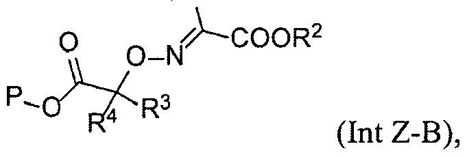
wherein
P is an acid-labile oxygen protecting group,
R', R2, R3 and R4 are each independently Cue alkyl,
to provide the compound of formula Int Z-C.
16. A compound of formula Int Z-C:

wherein
P is an acid-labile oxygen protecting group,
R1, R3 and R4 are each independently Ci-e alkyl.
17. The compound of claim 16, wherein P is tert-butyl.
18. The compound of claim 16 or 17, wherein R1 is methyl, ethyl, or isopropyl.
19. The compound of any one of claims 16 to 18, wherein R3 and R4 are each independently methyl or ethyl.
20. The compound of claim 16, wherein the compound of formula Int Z-C has the structure of Int C:

Priority Applications (1)
| Application Number | Priority Date | Filing Date | Title |
|---|---|---|---|
| US15/536,545 US10059680B2 (en) | 2014-12-18 | 2015-12-18 | Thiadiazolyl-oximinoacetic acid derivative compounds |
Applications Claiming Priority (4)
| Application Number | Priority Date | Filing Date | Title |
|---|---|---|---|
| US201462093775P | 2014-12-18 | 2014-12-18 | |
| US62/093,775 | 2014-12-18 | ||
| US201462097861P | 2014-12-30 | 2014-12-30 | |
| US62/097,861 | 2014-12-30 |
Publications (1)
| Publication Number | Publication Date |
|---|---|
| WO2016100897A1 true WO2016100897A1 (en) | 2016-06-23 |
Family
ID=56127722
Family Applications (1)
| Application Number | Title | Priority Date | Filing Date |
|---|---|---|---|
| PCT/US2015/066839 Ceased WO2016100897A1 (en) | 2014-12-18 | 2015-12-18 | Thiadiazolyl-oximinoacetic acid derivative compounds |
Country Status (2)
| Country | Link |
|---|---|
| US (1) | US10059680B2 (en) |
| WO (1) | WO2016100897A1 (en) |
Cited By (5)
| Publication number | Priority date | Publication date | Assignee | Title |
|---|---|---|---|---|
| CN108003115A (en) * | 2017-11-28 | 2018-05-08 | 浙江东邦药业有限公司 | A kind of preparation method of ceftolozane side chains |
| US10035774B2 (en) | 2014-12-18 | 2018-07-31 | Merck Sharp & Dohme Corp. | Pyrazolyl carboxylic acid and pyrazolyl urea derivative compounds |
| US10059680B2 (en) | 2014-12-18 | 2018-08-28 | Merck Sharp & Dohme Corp. | Thiadiazolyl-oximinoacetic acid derivative compounds |
| US10214543B2 (en) | 2014-12-30 | 2019-02-26 | Merck Sharp & Dohme Corp. | Synthesis of cephalosporin compounds |
| US10308666B2 (en) | 2014-12-23 | 2019-06-04 | Merck Sharp & Dohme Corp. | 7-aminocephem derivative compounds |
Citations (4)
| Publication number | Priority date | Publication date | Assignee | Title |
|---|---|---|---|---|
| EP0064582A1 (en) * | 1978-12-29 | 1982-11-17 | Fujisawa Pharmaceutical Co., Ltd. | Starting compounds for preparing cephem compounds and processes for their preparation |
| JPH01135778A (en) * | 1987-11-19 | 1989-05-29 | Fujisawa Pharmaceut Co Ltd | Production of acetic acid derivative |
| US20050096306A1 (en) * | 2003-09-18 | 2005-05-05 | Fujisawa Pharmaceutical Co. Ltd. | Cephem compounds |
| US20070037786A1 (en) * | 2002-10-30 | 2007-02-15 | Wakunaga Pharmaceutical Co., Ltd. | Cephem compounds |
Family Cites Families (8)
| Publication number | Priority date | Publication date | Assignee | Title |
|---|---|---|---|---|
| KR101719556B1 (en) * | 2011-03-30 | 2017-03-24 | 주식회사 레고켐 바이오사이언스 | Novel cephalosporin derivatives and Pharmaceutical Compositions Comprising the Same |
| WO2015196077A1 (en) | 2014-06-20 | 2015-12-23 | Merck Sharp & Dohme Corp. | Reactions of thiadiazolyl-oximinoacetic acid derivative compounds |
| WO2016025813A1 (en) | 2014-08-15 | 2016-02-18 | Merck Sharp & Dohme Corp. | Intermediates in the synthesis of cephalosporin compounds |
| WO2016025839A1 (en) | 2014-08-15 | 2016-02-18 | Merck Sharp & Dohme Corp. | Synthesis of cephalosporin compounds |
| WO2016095860A1 (en) | 2014-12-18 | 2016-06-23 | Merck Sharp & Dohme Corp. | Pyrazolyl carboxylic acid and pyrazolyl urea derivative compounds |
| WO2016100897A1 (en) | 2014-12-18 | 2016-06-23 | Merck Sharp & Dohme Corp. | Thiadiazolyl-oximinoacetic acid derivative compounds |
| US20160176897A1 (en) | 2014-12-23 | 2016-06-23 | Merck Sharp & Dohme Corp. | 7-aminocephem derivative compounds |
| US10214543B2 (en) | 2014-12-30 | 2019-02-26 | Merck Sharp & Dohme Corp. | Synthesis of cephalosporin compounds |
-
2015
- 2015-12-18 WO PCT/US2015/066839 patent/WO2016100897A1/en not_active Ceased
- 2015-12-18 US US15/536,545 patent/US10059680B2/en active Active
Patent Citations (4)
| Publication number | Priority date | Publication date | Assignee | Title |
|---|---|---|---|---|
| EP0064582A1 (en) * | 1978-12-29 | 1982-11-17 | Fujisawa Pharmaceutical Co., Ltd. | Starting compounds for preparing cephem compounds and processes for their preparation |
| JPH01135778A (en) * | 1987-11-19 | 1989-05-29 | Fujisawa Pharmaceut Co Ltd | Production of acetic acid derivative |
| US20070037786A1 (en) * | 2002-10-30 | 2007-02-15 | Wakunaga Pharmaceutical Co., Ltd. | Cephem compounds |
| US20050096306A1 (en) * | 2003-09-18 | 2005-05-05 | Fujisawa Pharmaceutical Co. Ltd. | Cephem compounds |
Cited By (5)
| Publication number | Priority date | Publication date | Assignee | Title |
|---|---|---|---|---|
| US10035774B2 (en) | 2014-12-18 | 2018-07-31 | Merck Sharp & Dohme Corp. | Pyrazolyl carboxylic acid and pyrazolyl urea derivative compounds |
| US10059680B2 (en) | 2014-12-18 | 2018-08-28 | Merck Sharp & Dohme Corp. | Thiadiazolyl-oximinoacetic acid derivative compounds |
| US10308666B2 (en) | 2014-12-23 | 2019-06-04 | Merck Sharp & Dohme Corp. | 7-aminocephem derivative compounds |
| US10214543B2 (en) | 2014-12-30 | 2019-02-26 | Merck Sharp & Dohme Corp. | Synthesis of cephalosporin compounds |
| CN108003115A (en) * | 2017-11-28 | 2018-05-08 | 浙江东邦药业有限公司 | A kind of preparation method of ceftolozane side chains |
Also Published As
| Publication number | Publication date |
|---|---|
| US20170369459A1 (en) | 2017-12-28 |
| US10059680B2 (en) | 2018-08-28 |
Similar Documents
| Publication | Publication Date | Title |
|---|---|---|
| EP3464245B1 (en) | Benzazepine dicarboxamide compounds with tertiary amide function | |
| US10035774B2 (en) | Pyrazolyl carboxylic acid and pyrazolyl urea derivative compounds | |
| WO2016100897A1 (en) | Thiadiazolyl-oximinoacetic acid derivative compounds | |
| EP3464274A1 (en) | Benzazepine dicarboxamide compounds with secondary amide function | |
| US10941161B2 (en) | Intermediates in the synthesis of cephalosporin compounds | |
| US10214543B2 (en) | Synthesis of cephalosporin compounds | |
| EP3592755A1 (en) | Glucuronide prodrugs of tofacitinib | |
| KR20200010440A (en) | Glucuronide Prodrug of Janus Kinase Inhibitor | |
| EP2609099A2 (en) | Sitagliptin, salts and polymorphs thereof | |
| US11926633B2 (en) | Synthesis methods for upadacitinib and intermediate thereof | |
| ES2665546T3 (en) | Synthesis of Triazolopyrimidine Compounds | |
| WO2022109242A1 (en) | Process for preparing 7-chloro-6-fluoro-1-(2-isopropyl-4-methylpyridin-3- yl)pyridof[2,3-d]pyrimidine-2,4(1h,3h)-dione | |
| US10308666B2 (en) | 7-aminocephem derivative compounds | |
| AU2019339994B2 (en) | Furo[3,4-b]pyrrole-containing BTK inhibitor | |
| EP3515915B1 (en) | Process for preparing beta-lactamase inhibitor hydroxylurea intermediates | |
| WO2004083172A2 (en) | Process for the preparation of 7-amino (p-hydroxyphenylglyclyamido) cephem compounds | |
| MX2007000907A (en) | Synthesis of 6,7-dihydro-5h-imidazo[1,2-a]imidazole-3-sulfonic acid amides. | |
| US20190040066A1 (en) | Process for the preparation of phosphatidylinositol 3-kinase inhibitor | |
| AU2020397222B2 (en) | Process and intermediates for the production of formula (i) | |
| CA2637214C (en) | Process for preparing 8-azabicylo[3.2.1]octan-3-one intermediates to 5-ht4 receptor agonist compounds | |
| AU2023257102A1 (en) | Method for producing 7h-pyrrolo[2,3-d]pyrimidine-4-amine derivative | |
| WO2025240465A1 (en) | Processes for preparing macrocyclic compounds | |
| WO2024228132A1 (en) | Fused bicyclic heterocyclyl compounds as ccr4 modulators | |
| HK40092933B (en) | Process for preparing 7-chloro-6-fluoro-1-(2-isopropyl-4-methylpyridin-3- yl)pyridof[2,3-d]pyrimidine-2,4(1h,3h)-dione | |
| HK40092933A (en) | Process for preparing 7-chloro-6-fluoro-1-(2-isopropyl-4-methylpyridin-3- yl)pyridof[2,3-d]pyrimidine-2,4(1h,3h)-dione |
Legal Events
| Date | Code | Title | Description |
|---|---|---|---|
| 121 | Ep: the epo has been informed by wipo that ep was designated in this application |
Ref document number: 15871219 Country of ref document: EP Kind code of ref document: A1 |
|
| WWE | Wipo information: entry into national phase |
Ref document number: 15536545 Country of ref document: US |
|
| NENP | Non-entry into the national phase |
Ref country code: DE |
|
| 122 | Ep: pct application non-entry in european phase |
Ref document number: 15871219 Country of ref document: EP Kind code of ref document: A1 |