WO2016096040A1 - Burner cap for use in a gas burner assembly - Google Patents
Burner cap for use in a gas burner assembly Download PDFInfo
- Publication number
- WO2016096040A1 WO2016096040A1 PCT/EP2014/078740 EP2014078740W WO2016096040A1 WO 2016096040 A1 WO2016096040 A1 WO 2016096040A1 EP 2014078740 W EP2014078740 W EP 2014078740W WO 2016096040 A1 WO2016096040 A1 WO 2016096040A1
- Authority
- WO
- WIPO (PCT)
- Prior art keywords
- burner
- formed sheet
- metal
- burner cap
- cap
- Prior art date
- Legal status (The legal status is an assumption and is not a legal conclusion. Google has not performed a legal analysis and makes no representation as to the accuracy of the status listed.)
- Ceased
Links
Images



Classifications
-
- F—MECHANICAL ENGINEERING; LIGHTING; HEATING; WEAPONS; BLASTING
- F23—COMBUSTION APPARATUS; COMBUSTION PROCESSES
- F23D—BURNERS
- F23D14/00—Burners for combustion of a gas, e.g. of a gas stored under pressure as a liquid
- F23D14/02—Premix gas burners, i.e. in which gaseous fuel is mixed with combustion air upstream of the combustion zone
- F23D14/04—Premix gas burners, i.e. in which gaseous fuel is mixed with combustion air upstream of the combustion zone induction type, e.g. Bunsen burner
- F23D14/06—Premix gas burners, i.e. in which gaseous fuel is mixed with combustion air upstream of the combustion zone induction type, e.g. Bunsen burner with radial outlets at the burner head
-
- F—MECHANICAL ENGINEERING; LIGHTING; HEATING; WEAPONS; BLASTING
- F23—COMBUSTION APPARATUS; COMBUSTION PROCESSES
- F23D—BURNERS
- F23D2212/00—Burner material specifications
-
- F—MECHANICAL ENGINEERING; LIGHTING; HEATING; WEAPONS; BLASTING
- F23—COMBUSTION APPARATUS; COMBUSTION PROCESSES
- F23D—BURNERS
- F23D2213/00—Burner manufacture specifications
-
- F—MECHANICAL ENGINEERING; LIGHTING; HEATING; WEAPONS; BLASTING
- F23—COMBUSTION APPARATUS; COMBUSTION PROCESSES
- F23D—BURNERS
- F23D2900/00—Special features of, or arrangements for burners using fluid fuels or solid fuels suspended in a carrier gas
- F23D2900/14—Special features of gas burners
- F23D2900/14061—Special features of gas burners for cooking ranges having a coated burner cap
Definitions
- the present invention relates to a gas cooking appliance.
- the present invention particularly relates to the gas burner assembly of the gas cooking appliance.
- the present invention more particularly relates to the burner cap of the gas burner assembly.
- a gas cooking appliance generally comprises a cooktop and at least one gas burner assembly which is built into the cooktop.
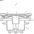
- Fig. 1 shows a prior art gas burner assembly (2 ⁇ ).
- the gas burner assembly (2 ⁇ ) comprises a burner head (3 ⁇ ) which has a plurality of circumferentially arranged openings (4 ⁇ ) for emitting flames, a burner base (15 ⁇ ) which supports and supplies the burner head (3 ⁇ ) with the gas/air mixture and a burner cap (1 ⁇ ) which is placed onto a seat (5 ⁇ ) of the burner head (3) ⁇ .
- the burner cap (1 ⁇ ) comprises a bottom surface (7 ⁇ ) which sustains burning of the gas/air mixture and spreads the flames towards the openings (4 ⁇ ) and a top surface (6 ⁇ ) which partly conceals the burner head (3 ⁇ ).
- the gas burner assembly (2 ⁇ ) also comprises an ignition spark plug which is utilized to ignite the gas/air mixture which flows to the outside through the openings (4 ⁇ ).
- a proper installation of the gas burner assembly (2 ⁇ ) is of utmost importance. Particularly in a high capacity gas burner assembly (2 ⁇ ), when the burner cap (1 ⁇ ) is slightly dislodged, the gas begins to rapidly accumulate in the vicinity of the openings (4 ⁇ ) and causes a violent explosion when it is eventually ignited. Such an explosion poses a risk to the safety and health of the user. Therefore, it is customary to produce the burner head (3 ⁇ ) and the burner cap (1 ⁇ ) from comparatively heavy and thick materials which prevent misalignment and dislodging when the appliance is moved or hit by the user.
- the massive burner cap (1 ⁇ ) is generally manufactured through cold/warm forging in which a die is used to shape the work piece.
- the provision of a properly machined die that is sufficiently strong to withstand the compressive forces during the production of the heavy and thick burner cap (1 ⁇ ) is comparatively expensive. Therefore, a drawback of the prior art burner cap (1 ⁇ ) is that its overall production costs are comparatively high.
- Another drawback is that during the forging process, the die and/or the burner cap (1 ⁇ ) occasionally breaks.
- Another drawback is that due to the small irregularities in the die surface, the curved portions of the burner cap (1 ⁇ ) cannot be evenly obtained.
- Another drawback is that the enameling process of the burner cap (1 ⁇ ) becomes difficult due its comparatively high mass.
- Another drawback is that the thermal efficiency of the gas cooking appliance drops with an increasing mass of the burner cap (1 ⁇ ).
- An objective of the present invention is to provide an improved burner cap for use in a gas burner assembly of a gas cooking appliance which overcomes the aforementioned drawbacks of the prior art in a cost-effective way and which enables an easy manufacturing.
- the burner cap of the present invention comprises at least two formed sheet-metals which together define the top surface and the bottom surface thereof.
- the formed sheet-metals are joined with each other.
- the manufacturing process has been simplified and the overall costs have been reduced.
- the sheet-metals can be formed by comparatively weaker compressive/tension forces, a breakage of the die has been prevented and its lifetime has been prolonged.
- the weight of the burner cap can be adjusted to the desired amount by choosing the correct thickness of the sheet-metal.
- the burner can be more easily enameled.
- the thermal efficiency of the cooking appliance has also been improved. Thereby, the consumer satisfaction can be increased.
- the burner cap is manufactured from two sheet-metals which are separately formed, for example through a die forming process, in particular through stamping by using a press and a die, a deep drawing process or the like.
- the two sheet-metals are subsequently joined in order to attain the closed shape which is defined by the respective top surface and the bottom surface of the burner cap.
- the sheet-metals are joined through a press-fitting process, a welding process or through any other process well known to those skilled in the art.
- the two metal sheets are formed with various different shapes which facilitate the attachment and the joining process, improve the structural stability, prevent misalignment and dislodging, sustain stable burning of the gas/air mixture and increase the thermal efficiency.
- the formed sheet-metals have a generally circular outline. However, the two formed sheet-metals may assume an annular shape, an oblong shape or a polygonal shape, in particular a rectangular shape in accordance with the specific design of the cooktop.
- either one or both of the two formed metal sheets have an upwardly or downwardly bending skirt-like flange.
- the flanges may be straight, inclined or curved.
- either one or both of the two formed metal sheets have a raised, lowered, a concave, a convex, a flat, a tapered central section and/or outer section.
- the present invention also provides a gas burner assembly which has the burner cap according to the present invention.
- the present invention also provides a gas cooking appliance which comprises at least one gas burner assembly according to the present invention.
- Figure 1 – is a sectional view of a prior art gas burner assembly
- Figure 2 – is a sectional view of a gas burner assembly which has a burner cap according to an embodiment of the present invention
- Figure 3 – is a sectional view of the burner cap as shown in Fig. 2;
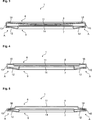
- Figure 4 – is a sectional view of a burner cap according to another embodiment of the present invention.
- Figure 5 – is a sectional view of a burner cap according to another embodiment of the present invention.
- Figure 6 – is a sectional view of a burner cap according to another embodiment of the present invention.
- Figure 7 – is a sectional view of a burner cap according to another embodiment of the present invention.
- Figure 8 – is a partial enlarged sectional view of a burner cap according to another embodiment of the present invention.
- the burner cap (1) is suitable for use in the gas burner assembly (2) of the gas cooking appliance (not shown).
- the gas burner assembly (2) comprises a burner head (3) which has a plurality of circumferentially arranged openings (4) for emitting flames and a circumferential seat (5) which is suitable for releasably supporting the burner cap (1) (Fig. 2 to 8).
- the cooking appliance comprises a cooktop (not shown) which is suitable for mounting at least one gas burner assembly (2).
- the burner cap (1) comprises a top surface (6) and a bottom surface (7).
- the top surface (6) at least partly conceals the burner head (3).
- the bottom surface (7) spreads the flames towards the openings (4).
- the burner cap (1) of the present invention comprises a least two formed sheet-metals (8, 9) which together define the top surface (6) and the bottom surface (7).
- the formed sheet-metals (8, 9) are joined with each other.
- the gas burner assembly (2) of the present invention comprises the burner cap (1) according to the present invention.
- the burner cap (1) can be releasably placed on the seat (5).
- the gas cooking appliance of the present invention comprises at least one gas burner assembly (2) according to the present invention.
- Each gas burner assembly (2) is built into the cooktop (Fig. 2 to 8).
- the burner cap (1) comprises a press-fit joint (A) which joins the formed sheet-metals (8, 9) with each other (Fig. 2 to 5).
- the burner cap (1) comprises a welding joint (B) which joins the formed sheet-metals (8, 9) with each other (Fig. 6 and 7).
- the burner cap comprises two formed sheet-metals (8, 9).
- the first formed sheet-metal (8) defines the top surface (6).
- the second formed sheet-metal (9) defines the bottom surface (7) (Fig. 2 to 8).
- the periphery of the first formed sheet-metal (8) embraces the periphery of the second formed sheet-metal (9).
- the periphery of the first formed sheet-metal (8) comprises a downwardly projecting skirt (10) (Fig. 2 to 8).
- the skirt (10) makes an acute angle ⁇ with respect to the vertical axis (z).
- the acute angle ⁇ is preferably less than 10 degrees, more preferably about 6 degrees (Fig. 8).
- the first formed sheet-metal (8) comprises a concave central section (11) (Fig. 2, 3, 6 and 8). In a version of this embodiment both the central section (11) and the outer section (16) of the first formed sheet-metal (8) is concave shaped.
- the first formed sheet-metal (8) comprises a lowered central section (11) (Fig. 4 and 7).
- the outer section (16) of the first formed sheet-metal (8) is substantially flat (Fig. 4 and 7).
- the first formed sheet-metal (8) comprises a raised central section (11) (Fig. 5).
- the outer section (16) of the first formed sheet-metal (8) is tapered (Fig. 5).
- the second formed sheet-metal (9) comprises a circumferentially tapered outer section (12) (Fig. 2 to 8).
- the periphery of the second formed sheet-metal (9) comprises an upwardly projecting skirt (13) (Fig. 6 and 7).
- the downwardly projecting skirt (10) of the first formed sheet-metal (8) firmly contacts the upwardly projecting skirt (13) of the second formed sheet-metal (9).
- the skirts (10, 13) are joined by the welding joint (B).
- the second formed sheet-metal (9) comprises a raised central section (14) (Fig. 2 to 8).
- first formed sheet-metal (8) and the second formed sheet-metal (9) both have a circular outline (Fig. 2 to 8).
- the two formed sheet-metals (8, 9) have an oblong shape or a polygonal shape.
- the burner cap (1) including the formed sheet-metals (8, 9) are enameled.
- the gas burner assembly (2) comprises a burner base (15) which supports the burner head (3).
- the burner base (15) supplies the burner head (3) with the gas/air mixture to be combusted (Fig. 2 to 8).
Landscapes
- Engineering & Computer Science (AREA)
- Chemical & Material Sciences (AREA)
- Combustion & Propulsion (AREA)
- Mechanical Engineering (AREA)
- General Engineering & Computer Science (AREA)
- Gas Burners (AREA)
Abstract
The present invention relates to a burner cap (1) for use in a gas burner assembly (2) of a cooking appliance. The gas burner assembly (2) comprises a burner head (3) which has a plurality of openings (4) for emitting flames and a seat (5) for releasably supporting the burner cap (1). The burner cap (1) comprises a top surface (6) which at least partly conceals the burner head (3) and a bottom surface (7) which spreads the flames towards the openings (4). The burner cap (1) of the present invention comprises two or more than two formed sheet-metals (8, 9) which together define the top surface (6) and the bottom surface (7). The formed sheet-metals (8, 9) are joined with each other.
Description
The present invention relates to a gas cooking appliance. The present invention particularly relates to the gas burner assembly of the gas cooking appliance. The present invention more particularly relates to the burner cap of the gas burner assembly.
Gas cooking appliances which use flammable gases such as natural gas or liquefied petroleum gas are commonly known. A gas cooking appliance generally comprises a cooktop and at least one gas burner assembly which is built into the cooktop. Fig. 1 shows a prior art gas burner assembly (2´). The gas burner assembly (2´) comprises a burner head (3´) which has a plurality of circumferentially arranged openings (4´) for emitting flames, a burner base (15´) which supports and supplies the burner head (3´) with the gas/air mixture and a burner cap (1´) which is placed onto a seat (5´) of the burner head (3)´. The burner cap (1´) comprises a bottom surface (7´) which sustains burning of the gas/air mixture and spreads the flames towards the openings (4´) and a top surface (6´) which partly conceals the burner head (3´). The gas burner assembly (2´) also comprises an ignition spark plug which is utilized to ignite the gas/air mixture which flows to the outside through the openings (4´).
A proper installation of the gas burner assembly (2´) is of utmost importance. Particularly in a high capacity gas burner assembly (2´), when the burner cap (1´) is slightly dislodged, the gas begins to rapidly accumulate in the vicinity of the openings (4´) and causes a violent explosion when it is eventually ignited. Such an explosion poses a risk to the safety and health of the user. Therefore, it is customary to produce the burner head (3´) and the burner cap (1´) from comparatively heavy and thick materials which prevent misalignment and dislodging when the appliance is moved or hit by the user.
The massive burner cap (1´) is generally manufactured through cold/warm forging in which a die is used to shape the work piece. The provision of a properly machined die that is sufficiently strong to withstand the compressive forces during the production of the heavy and thick burner cap (1´) is comparatively expensive. Therefore, a drawback of the prior art burner cap (1´) is that its overall production costs are comparatively high. Another drawback is that during the forging process, the die and/or the burner cap (1´) occasionally breaks. Another drawback is that due to the small irregularities in the die surface, the curved portions of the burner cap (1´) cannot be evenly obtained. Another drawback is that the enameling process of the burner cap (1´) becomes difficult due its comparatively high mass. Another drawback is that the thermal efficiency of the gas cooking appliance drops with an increasing mass of the burner cap (1´).
An objective of the present invention is to provide an improved burner cap for use in a gas burner assembly of a gas cooking appliance which overcomes the aforementioned drawbacks of the prior art in a cost-effective way and which enables an easy manufacturing.
This objective has been achieved by the burner cap as defined in claim 1, the gas burner assembly as defined in claim 14 and the gas cooking appliance as defined in claim 15. Further achievements have been attained by the subject-matters respectively defined in the dependent claims.
The burner cap of the present invention comprises at least two formed sheet-metals which together define the top surface and the bottom surface thereof. The formed sheet-metals are joined with each other.
With the present invention, particularly by virtue of the formed sheet-metal structure of burner cap, the manufacturing process has been simplified and the overall costs have been reduced. As the sheet-metals can be formed by comparatively weaker compressive/tension forces, a breakage of the die has been prevented and its lifetime has been prolonged. The weight of the burner cap can be adjusted to the desired amount by choosing the correct thickness of the sheet-metal. With the present invention, particularly by virtue of the formed sheet-metal structure, the burner can be more easily enameled. With the present invention, particularly by virtue of the formed sheet-metal structure, the thermal efficiency of the cooking appliance has also been improved. Thereby, the consumer satisfaction can be increased.
In an embodiment, the burner cap is manufactured from two sheet-metals which are separately formed, for example through a die forming process, in particular through stamping by using a press and a die, a deep drawing process or the like. The two sheet-metals are subsequently joined in order to attain the closed shape which is defined by the respective top surface and the bottom surface of the burner cap. The sheet-metals are joined through a press-fitting process, a welding process or through any other process well known to those skilled in the art. The two metal sheets are formed with various different shapes which facilitate the attachment and the joining process, improve the structural stability, prevent misalignment and dislodging, sustain stable burning of the gas/air mixture and increase the thermal efficiency. The formed sheet-metals have a generally circular outline. However, the two formed sheet-metals may assume an annular shape, an oblong shape or a polygonal shape, in particular a rectangular shape in accordance with the specific design of the cooktop.
In alternative embodiments, either one or both of the two formed metal sheets have an upwardly or downwardly bending skirt-like flange. The flanges may be straight, inclined or curved.
In other alternative embodiments, either one or both of the two formed metal sheets have a raised, lowered, a concave, a convex, a flat, a tapered central section and/or outer section.
The present invention also provides a gas burner assembly which has the burner cap according to the present invention.
The present invention also provides a gas cooking appliance which comprises at least one gas burner assembly according to the present invention.
Additional advantages of the burner cap, the gas burner assembly and the cooking appliance of the present invention will become more apparent with the detailed description of the embodiments with reference to the accompanying drawings in which:
Figure 1 – is a sectional view of a prior art gas burner assembly;
Figure 2 – is a sectional view of a gas burner assembly which has a burner cap according to an embodiment of the present invention;
Figure 3 – is a sectional view of the burner cap as shown in Fig. 2;
Figure 4 – is a sectional view of a burner cap according to another embodiment of the present invention;
Figure 5 – is a sectional view of a burner cap according to another embodiment of the present invention;
Figure 6 – is a sectional view of a burner cap according to another embodiment of the present invention;
Figure 7 – is a sectional view of a burner cap according to another embodiment of the present invention;
Figure 8 – is a partial enlarged sectional view of a burner cap according to another embodiment of the present invention.
The reference signs appearing on the drawings relate to the following technical features.
- Burner cap
- Burner assembly
- Burner head
- Opening
- Seat
- Top surface
- Bottom surface
- 1st sheet-metal
- 2nd sheet-metal
- Skirt
- Central section
- Outer section
- Skirt
- Central section
- Burner base
- Outer section
The burner cap (1) is suitable for use in the gas burner assembly (2) of the gas cooking appliance (not shown).
The gas burner assembly (2) comprises a burner head (3) which has a plurality of circumferentially arranged openings (4) for emitting flames and a circumferential seat (5) which is suitable for releasably supporting the burner cap (1) (Fig. 2 to 8).
The cooking appliance comprises a cooktop (not shown) which is suitable for mounting at least one gas burner assembly (2).
The burner cap (1) comprises a top surface (6) and a bottom surface (7). The top surface (6) at least partly conceals the burner head (3). The bottom surface (7) spreads the flames towards the openings (4).
The burner cap (1) of the present invention comprises a least two formed sheet-metals (8, 9) which together define the top surface (6) and the bottom surface (7). The formed sheet-metals (8, 9) are joined with each other.
The gas burner assembly (2) of the present invention comprises the burner cap (1) according to the present invention. The burner cap (1) can be releasably placed on the seat (5).
The gas cooking appliance of the present invention comprises at least one gas burner assembly (2) according to the present invention. Each gas burner assembly (2) is built into the cooktop (Fig. 2 to 8).
In an embodiment, the burner cap (1) comprises a press-fit joint (A) which joins the formed sheet-metals (8, 9) with each other (Fig. 2 to 5).
In an alternative embodiment, the burner cap (1) comprises a welding joint (B) which joins the formed sheet-metals (8, 9) with each other (Fig. 6 and 7).
In another embodiment, the burner cap comprises two formed sheet-metals (8, 9). The first formed sheet-metal (8) defines the top surface (6). The second formed sheet-metal (9) defines the bottom surface (7) (Fig. 2 to 8).
In another embodiment, the periphery of the first formed sheet-metal (8) embraces the periphery of the second formed sheet-metal (9).
In another embodiment, the periphery of the first formed sheet-metal (8) comprises a downwardly projecting skirt (10) (Fig. 2 to 8). In a version of this embodiment, the skirt (10) makes an acute angle Ɵ with respect to the vertical axis (z). In another version of this embodiment, the acute angle Ɵ is preferably less than 10 degrees, more preferably about 6 degrees (Fig. 8).
In another embodiment, the first formed sheet-metal (8) comprises a concave central section (11) (Fig. 2, 3, 6 and 8). In a version of this embodiment both the central section (11) and the outer section (16) of the first formed sheet-metal (8) is concave shaped.
In another embodiment, the first formed sheet-metal (8) comprises a lowered central section (11) (Fig. 4 and 7). In a version of this embodiment the outer section (16) of the first formed sheet-metal (8) is substantially flat (Fig. 4 and 7).
In another embodiment, the first formed sheet-metal (8) comprises a raised central section (11) (Fig. 5). In a version of this embodiment the outer section (16) of the first formed sheet-metal (8) is tapered (Fig. 5).
In another embodiment, the second formed sheet-metal (9) comprises a circumferentially tapered outer section (12) (Fig. 2 to 8).
In another embodiment, the periphery of the second formed sheet-metal (9) comprises an upwardly projecting skirt (13) (Fig. 6 and 7). In a version of this embodiment, the downwardly projecting skirt (10) of the first formed sheet-metal (8) firmly contacts the upwardly projecting skirt (13) of the second formed sheet-metal (9). The skirts (10, 13) are joined by the welding joint (B).
In another embodiment, the second formed sheet-metal (9) comprises a raised central section (14) (Fig. 2 to 8).
In another embodiment, the first formed sheet-metal (8) and the second formed sheet-metal (9) both have a circular outline (Fig. 2 to 8). Alternatively, the two formed sheet-metals (8, 9) have an oblong shape or a polygonal shape.
In another embodiment, the burner cap (1) including the formed sheet-metals (8, 9) are enameled.
In another embodiment, the gas burner assembly (2) comprises a burner base (15) which supports the burner head (3). The burner base (15) supplies the burner head (3) with the gas/air mixture to be combusted (Fig. 2 to 8).
Claims (15)
- A burner cap (1) suitable for use in a gas burner assembly (2) of a cooking appliance, the gas burner assembly (2) comprising a burner head (3) which has a plurality of openings (4) for emitting flames and a seat (5) for releasably supporting the burner cap (1), the burner cap (1) comprising a top surface (6) which at least partly conceals the burner head (3) and a bottom surface (7) which spreads the flames towards the openings (4), characterized in that two or more than two formed sheet-metals (8, 9) which together define the top surface (6) and the bottom surface (7), wherein the formed sheet-metals (8, 9) are joined with each other.
- The burner cap (1) according to claim 1, characterized in that a welding joint which joins the formed sheet-metals (8, 9) with each other.
- The burner cap (1) according to claim 1, characterized in that a press-fit joint which joins the formed sheet-metals (8, 9) with each other.
- The burner cap (1) according to any one of claims 1 to 3, characterized in that two formed sheet-metals (8, 9), wherein the first formed sheet-metal (8) defines the top surface (6) and the second formed sheet-metal (9) defines the bottom surface (7).
- The burner cap (1) according to claim 4, characterized in that the periphery of the first formed sheet-metal (8) embraces the periphery of the second formed sheet-metal (9).
- The burner cap (1) according to claim 4 or 5, characterized in that the periphery of the first formed sheet-metal (8) comprising a downwardly projecting skirt (10).
- The burner cap (1) according to any one of claims 4 to 6, characterized in that the first formed sheet-metal (8) comprising a concave central section (11).
- The burner cap (1) according to any one of claims 4 to 6, characterized in that the first formed sheet-metal (8) comprising a lowered central section (11).
- The burner cap (1) according to any one of claims 4 to 6, characterized in that the first formed sheet-metal (8) comprising a raised central section (11).
- The burner cap (1) according to any one of claims 4 to 9, characterized in that the second formed sheet-metal (9) comprising a circumferentially tapered outer section (12).
- The burner cap (1) according to any one of claims 4 to 10, characterized in that the periphery of the second formed sheet-metal (9) comprising an upwardly projecting skirt (13).
- The burner cap (1) according to any one of claims 4 to 11, characterized in that the second formed sheet-metal (9) comprising a raised central section (14).
- The burner cap (1) according to claim any one of claims 4 to 12, characterized in that the first formed sheet-metal (8) and the second formed sheet-metal (9) both have a circular outline.
- A gas burner assembly (2) comprising a burner head (3) which has a plurality of openings (4) for emitting flames and a seat (5) for releasably supporting a burner cap (1), the gas burner assembly (2), characterized in that the burner cap (1) as defined in any one of claims 1 to 13.
- A gas cooking appliance comprising a cooktop, characterized in that one or more than one gas burner assembly (2) as defined in claim 14, wherein each gas burner assembly (2) is built into the cooktop.
Priority Applications (1)
| Application Number | Priority Date | Filing Date | Title |
|---|---|---|---|
| PCT/EP2014/078740 WO2016096040A1 (en) | 2014-12-19 | 2014-12-19 | Burner cap for use in a gas burner assembly |
Applications Claiming Priority (1)
| Application Number | Priority Date | Filing Date | Title |
|---|---|---|---|
| PCT/EP2014/078740 WO2016096040A1 (en) | 2014-12-19 | 2014-12-19 | Burner cap for use in a gas burner assembly |
Publications (1)
| Publication Number | Publication Date |
|---|---|
| WO2016096040A1 true WO2016096040A1 (en) | 2016-06-23 |
Family
ID=52134206
Family Applications (1)
| Application Number | Title | Priority Date | Filing Date |
|---|---|---|---|
| PCT/EP2014/078740 Ceased WO2016096040A1 (en) | 2014-12-19 | 2014-12-19 | Burner cap for use in a gas burner assembly |
Country Status (1)
| Country | Link |
|---|---|
| WO (1) | WO2016096040A1 (en) |
Cited By (2)
| Publication number | Priority date | Publication date | Assignee | Title |
|---|---|---|---|---|
| USD926520S1 (en) | 2019-01-09 | 2021-08-03 | Whirlpool Corporation | Cooking burner |
| EP4012258A1 (en) * | 2020-12-08 | 2022-06-15 | Whirlpool Corporation | Burner cap for a burner assembly |
Citations (6)
| Publication number | Priority date | Publication date | Assignee | Title |
|---|---|---|---|---|
| FR1197178A (en) * | 1958-05-28 | 1959-11-27 | Procedes Sauter | Venturi gas burner |
| AU3252468A (en) * | 1969-01-10 | 1970-07-16 | Radiation (Australia) Proprietary Limited | Improvement in and relating togas burners |
| AU593990B2 (en) * | 1987-04-10 | 1990-02-22 | Simpson Pty Limited | Gas burners |
| KR20020067116A (en) * | 2001-02-15 | 2002-08-22 | 엘지전자주식회사 | Top burner for gas oven |
| WO2004044490A1 (en) * | 2002-11-12 | 2004-05-27 | Sabaf S.P.A. | Gas burner with separate feeding of the flame crowns |
| US20110120446A1 (en) * | 2009-11-23 | 2011-05-26 | Whirlpool Corporation | Diffusion cap burner for gas cooking appliance |
-
2014
- 2014-12-19 WO PCT/EP2014/078740 patent/WO2016096040A1/en not_active Ceased
Patent Citations (6)
| Publication number | Priority date | Publication date | Assignee | Title |
|---|---|---|---|---|
| FR1197178A (en) * | 1958-05-28 | 1959-11-27 | Procedes Sauter | Venturi gas burner |
| AU3252468A (en) * | 1969-01-10 | 1970-07-16 | Radiation (Australia) Proprietary Limited | Improvement in and relating togas burners |
| AU593990B2 (en) * | 1987-04-10 | 1990-02-22 | Simpson Pty Limited | Gas burners |
| KR20020067116A (en) * | 2001-02-15 | 2002-08-22 | 엘지전자주식회사 | Top burner for gas oven |
| WO2004044490A1 (en) * | 2002-11-12 | 2004-05-27 | Sabaf S.P.A. | Gas burner with separate feeding of the flame crowns |
| US20110120446A1 (en) * | 2009-11-23 | 2011-05-26 | Whirlpool Corporation | Diffusion cap burner for gas cooking appliance |
Cited By (5)
| Publication number | Priority date | Publication date | Assignee | Title |
|---|---|---|---|---|
| USD926520S1 (en) | 2019-01-09 | 2021-08-03 | Whirlpool Corporation | Cooking burner |
| USD951019S1 (en) | 2019-01-09 | 2022-05-10 | Whirlpool Corporation | Cooking burner |
| USD1038694S1 (en) | 2019-01-09 | 2024-08-13 | Whirlpool Corporation | Cooking burner |
| EP4012258A1 (en) * | 2020-12-08 | 2022-06-15 | Whirlpool Corporation | Burner cap for a burner assembly |
| US11421890B2 (en) | 2020-12-08 | 2022-08-23 | Whirlpool Corporation | Burner cap for a burner assembly |
Similar Documents
| Publication | Publication Date | Title |
|---|---|---|
| US20100035197A1 (en) | Cap for a gas burner | |
| KR101577538B1 (en) | Brazier for camping | |
| CN102434883B (en) | Burner for ranges | |
| US20170370575A1 (en) | A gas burner assembly | |
| JP5479962B2 (en) | Plate burner for boiler | |
| WO2016096040A1 (en) | Burner cap for use in a gas burner assembly | |
| CN204880123U (en) | Outer ring fire lid | |
| CN105465788A (en) | Combined fire cover of gas stove | |
| US10774956B2 (en) | Orifice holder construction | |
| CN204923124U (en) | Combination of fire lid | |
| JP2015230144A (en) | Cooking stove burner | |
| CN203785015U (en) | High energy-collecting type gas stove | |
| JP4942701B2 (en) | Stove burner | |
| CN107062309A (en) | A kind of infrared burner for improving sparking mode | |
| US20170038076A1 (en) | Gas burner, in particular for a cooking top for household use | |
| CN210267217U (en) | Inner fire cover of household stove burner | |
| CN100593670C (en) | Stainless steel plate integral burner | |
| EP3441669B1 (en) | Improved orifice holder construction | |
| CN204730258U (en) | Gas kitchen ranges | |
| CN206291245U (en) | A kind of infrared burner for improving sparking mode | |
| CN106090912A (en) | A kind of integral type fire cover structure of cooker burner | |
| CN220152791U (en) | Center fire cover, burner and combustion stove | |
| JP2015230100A (en) | Stove burner | |
| CN109990292B (en) | Burner fire cover of gas cooker and gas cooker | |
| JP2014145512A (en) | Burner for cooking stove |
Legal Events
| Date | Code | Title | Description |
|---|---|---|---|
| 121 | Ep: the epo has been informed by wipo that ep was designated in this application |
Ref document number: 14815744 Country of ref document: EP Kind code of ref document: A1 |
|
| NENP | Non-entry into the national phase |
Ref country code: DE |
|
| 122 | Ep: pct application non-entry in european phase |
Ref document number: 14815744 Country of ref document: EP Kind code of ref document: A1 |