WO2016076307A1 - 鉄道車両用車輪のフランジ摩耗測定方法 - Google Patents
鉄道車両用車輪のフランジ摩耗測定方法 Download PDFInfo
- Publication number
- WO2016076307A1 WO2016076307A1 PCT/JP2015/081584 JP2015081584W WO2016076307A1 WO 2016076307 A1 WO2016076307 A1 WO 2016076307A1 JP 2015081584 W JP2015081584 W JP 2015081584W WO 2016076307 A1 WO2016076307 A1 WO 2016076307A1
- Authority
- WO
- WIPO (PCT)
- Prior art keywords
- wheel
- vehicle
- distance
- flange
- rail
- Prior art date
Links
Images


Classifications
-
- B—PERFORMING OPERATIONS; TRANSPORTING
- B61—RAILWAYS
- B61K—AUXILIARY EQUIPMENT SPECIALLY ADAPTED FOR RAILWAYS, NOT OTHERWISE PROVIDED FOR
- B61K9/00—Railway vehicle profile gauges; Detecting or indicating overheating of components; Apparatus on locomotives or cars to indicate bad track sections; General design of track recording vehicles
- B61K9/12—Measuring or surveying wheel-rims
-
- B—PERFORMING OPERATIONS; TRANSPORTING
- B61—RAILWAYS
- B61L—GUIDING RAILWAY TRAFFIC; ENSURING THE SAFETY OF RAILWAY TRAFFIC
- B61L27/00—Central railway traffic control systems; Trackside control; Communication systems specially adapted therefor
- B61L27/50—Trackside diagnosis or maintenance, e.g. software upgrades
- B61L27/57—Trackside diagnosis or maintenance, e.g. software upgrades for vehicles or vehicle trains, e.g. trackside supervision of train conditions
-
- G—PHYSICS
- G01—MEASURING; TESTING
- G01M—TESTING STATIC OR DYNAMIC BALANCE OF MACHINES OR STRUCTURES; TESTING OF STRUCTURES OR APPARATUS, NOT OTHERWISE PROVIDED FOR
- G01M17/00—Testing of vehicles
- G01M17/08—Railway vehicles
- G01M17/10—Suspensions, axles or wheels
-
- G—PHYSICS
- G01—MEASURING; TESTING
- G01B—MEASURING LENGTH, THICKNESS OR SIMILAR LINEAR DIMENSIONS; MEASURING ANGLES; MEASURING AREAS; MEASURING IRREGULARITIES OF SURFACES OR CONTOURS
- G01B21/00—Measuring arrangements or details thereof, where the measuring technique is not covered by the other groups of this subclass, unspecified or not relevant
- G01B21/02—Measuring arrangements or details thereof, where the measuring technique is not covered by the other groups of this subclass, unspecified or not relevant for measuring length, width, or thickness
Definitions
- the present invention relates to a method for directly measuring the amount of flange wear of a wheel of a railway vehicle online during traveling.
- the wheel of the railway vehicle will come into contact with the rail when traveling.
- the wheel worn by contact with the rail has a great influence on the motion performance of the railway vehicle. Therefore, in order to travel the railway vehicle safely, it is very important to manage the amount of wear of the wheels.
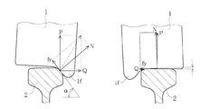
- FIG. 10 is a diagram schematically showing the force that the wheel 1 receives from the rail 2 during traveling in a curve section composed of a relaxation curve and a circular curve.
- the rail 2 on the left side of FIG. 10 indicates the rail 2 on the outer peripheral side of the curved section
- the rail 2 on the right side of the paper indicates the rail 2 on the inner peripheral side of the curved section.
- the outer circumference side of the curved section is referred to as the outer gauge side
- the inner circumference side of the curved section is referred to as the inner gauge side.
- the wheel load P that the wheel 1 exerts perpendicularly to the rail surface and the lateral pressure Q that the wheel 1 exerts on the side surface of the rail 2 are important management indexes.
- N represents a normal force
- fy represents a lateral creep force.
- the upright wear generated in the flange 1f of the wheel 1 is quickly found and the shape of the wheel 1 is optimized by cutting with a rotating tool (hereinafter referred to as rolling). This is one of the solutions.
- the upright wear refers to wear in which the throat 1th of the wheel 1 wears and the flange 1f becomes almost upright (the hatched portion in FIG. 11).
- Patent Document 1 the shape of the tread of the left and right wheels and the cross-sectional shape of the rail are measured by a shape measuring device, and these shape data are converted into discrete data at predetermined intervals in the wheel thickness direction.
- An apparatus for evaluating the contact characteristics of a rail is disclosed.
- Patent Document 2 discloses an apparatus and method for continuously measuring a change in the shape of a tread surface of a wheel over a circumferential direction.
- Patent Document 3 discloses a device that quantitatively estimates a change in flange angle due to wear in relation to a travel distance, based on the flange angle at the time of design.
- Patent Document 4 discloses a method and apparatus for measuring the shape of a wheel using a plurality of laser distance meters, and Patent Document 5 using a plurality of cameras and a plurality of laser distance meters. Yes.
- the distance to the wheel is measured using distance sensors installed on the outside and inside of the rail, and the wheel diameter and flange are determined from these measurement results and the distance data related to the installation of the both distance sensors.
- An apparatus for calculating the shape of a wheel such as thickness and flange height and a method for installing the apparatus are disclosed.
- Patent Documents 1 to 3 are not technologies that measure while the vehicle is running, but technologies that are premised on offline measurement. Therefore, it is difficult to ensure safety during vehicle travel in a timely manner.
- Patent Documents 4 to 7 use a plurality of cameras and a plurality of laser distance meters. Accordingly, the specification becomes complicated and man-hours are required for maintenance. In addition, since measurement values need to be processed separately, it is difficult to ensure safety during vehicle travel in a timely manner.
- Patent Documents 1 to 3 are techniques based on the premise that measurement is performed off-line. Is difficult.
- the techniques disclosed in Patent Documents 4 to 7 use a plurality of cameras and a plurality of laser distance meters, the specifications become complicated and a man-hour is required for maintenance.
- it is necessary to process measured values separately it is difficult to ensure safety during vehicle travel in a timely manner.
- the method of measuring the flange wear of the railway vehicle wheel of the present invention Install a laser distance meter on the outer track side of the circular curve section on the railway track, When the vehicle travels in the circular curve section, the laser distance meter measures the distance to the front rim surface of the wheel on the outer gauge side of the front shaft of the carriage that constitutes the vehicle, The most important feature is to obtain the flange wear amount by comparing the measured distance with the previously measured distance.
- the distance to the front rim surface of the wheel on the outer gauge side of the front shaft of the carriage measured with a laser rangefinder installed on the outer gauge side of the circular curved section is conventionally measured.
- the flange wear amount can be obtained only by comparing with the above distance.
- laser distance meters are installed at four locations where the curvature of the curved section is reversed, and the front rim surface of the wheel on the outer gauge side of the front shaft of the two-axis carriage that is traveling along the curved section with these laser distance meters.
- the distance up to this point is measured by the method of the present invention, it is possible to measure the flange wear amount of all the wheels of the two-shaft carriage.
- the flange wear amount of the wheel of the railway vehicle can be directly measured online while traveling in the curved section, and the flange wear amount of the wheel can be managed.
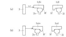
- FIG. 6 is a view similar to FIG.
- FIG. 5A when the wheel shaft (hereinafter referred to as the rear shaft) in the rearward direction of the carriage comes to a position facing the laser distance meter.
- FIG. 5 is a view similar to FIG. 4 when a wheel mounted on a railway vehicle is worn. It is a figure explaining an example of the installation position of the laser range finder used when implementing this invention method, (a) shows the case of an up line, (b) shows the case of a down line. It is a figure explaining the wheel which measures flange abrasion with the laser distance meter installed in the position shown in Drawing 6 (a). It is a figure explaining the wheel which measures flange abrasion with the laser distance meter installed in the position shown in Drawing 6 (b).
- (A) is the figure which showed the result of having measured the distance to the front rim surface of a wheel with the laser rangefinder about the vehicle equipped with the wheel immediately after rolling, (b) about the vehicle equipped with the wheel which 1 mm of flanges were worn It is the figure which showed the result of having measured the distance to the front rim surface of a wheel with a laser distance meter. It is a figure explaining the force which a wheel receives from a rail when a railroad vehicle passes through a curve section, and a paper surface left side shows an outer track side and a paper surface right side shows an inner track side. It is a figure explaining the upright wear which generate
- the present invention is installed on the outer track side of a circular curve section for the purpose of directly measuring on-line the flange wear amount of the wheel of a railway vehicle while traveling in a curved section to ensure safety during traveling. This was achieved by comparing the distance to the front rim surface of the wheel measured with a laser rangefinder.
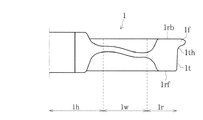
- FIG. 1 is a diagram for explaining the names of main parts of a railway vehicle wheel.
- the wheel 1 includes a boss portion 1h into which an axle is inserted, a rim portion 1r in contact with the rail 2, a boss portion 1h and a rim portion 1r. It is comprised from three parts of the board part 1w to connect.
- a tread surface 1t in contact with the rail 2 and a flange 1f continuous with the tread surface 1t via a throat 1th are formed.
- the side surface of the rim portion 1r on the side where the flange 1f is formed is referred to as a back rim surface 1rb, and the side surface opposite to the back rim surface 1rb is referred to as a front rim surface 1rf.
- the throat 1th of the wheel 1 on the outer gauge side of the front shaft Sf of the carriage B is pressed against the rail 2 as described above. Therefore, as the running time of the vehicle becomes longer, the amount of upright wear of the flange 1f of the wheel 1 increases, and the distance between the flange outer surfaces of both wheels 1 constituting the wheel shaft (see FIG. 2) becomes shorter.
- the distance between the flange outer surfaces of both wheels 1 constituting the wheel shaft is referred to as “flange outer surface distance”.
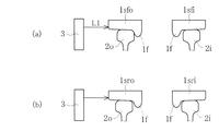
- the laser rangefinder 3 is installed outside the rail 2o on the outer track side in the circular curve section, and the front rim of the wheel 1sfo on the outer track side of the front shaft Sf running from the installation position.
- the wear amount of the flange 1f of the wheel 1 can be known.
- the front rim of the wheel 1sfo on the outer gauge side of the front axis Sf is measured by the laser distance meter 3.
- the distance L1 to the surface 1rf is measured (see FIG. 4A).
- the displacement in the vehicle width direction of the front shaft Sf is reset to the zero point, and the measurement by the laser rangefinder 3 when the vehicle equipped with the wheel 1sfo with the worn flange 1f travels in a curved section. Guarantees accuracy.
- the distance L2 to the front rim surface 1rf of the wheel 1sfo of the vehicle is measured by the laser distance meter 3 (FIG. 5 (a)). )reference).
- the rail on the inner track side is denoted as 2i.
- a wheel on the inner rail side of the front shaft Sf is denoted by 1 sfi
- a wheel on the outer rail side of the rear shaft Sr is denoted by 1 sro
- a wheel on the inner rail side of the rear shaft Sr is denoted by 1 sri.
- the wear amount of the flange 1f of the wheel 1sfo can be obtained by subtracting the measured distance L2 from the distance L1.
- the wear amount of the flange of the wheel is a change amount of (flange outer surface distance ⁇ wheel inner surface distance) / 2 with respect to a new wheel or a wheel immediately after rolling (see FIG. 2). As wear progresses, the amount of change in (flange outer surface distance ⁇ wheel inner surface distance) / 2 decreases.
- wheel inner surface distance means the distance between the wheel inner surfaces of both the wheels 1 which comprise a wheel shaft.
- the amount of wear time Evaluation can be performed.
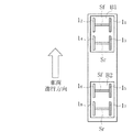
- the respective circular curve sections of the up line and the down line may be installed at two locations where the curvature of the rail 2 is reversed (see FIG. 6).
- the wheels 12 and 16 on the outer gauge side of the front shaft Sf of the biaxial carriage B1 located on the front side and the biaxial carriage B2 located on the rear side are measured by the laser distance meter 3a.
- the amount of wear of the flange 1f can be measured.
- the laser distance meter 3b measures the wear amount of the flanges 1f of the wheels 11 and 15 on the outer track side of the front shaft Sf of the biaxial cart B1 located on the front side and the biaxial cart B2 located on the rear side. Can do.
- the wheels 18 and 14 on the outer gauge side of the front shaft Sf of the biaxial cart B2 located on the front side and the biaxial cart B1 located on the rear side are measured by the laser distance meter 3c.
- the amount of wear of the flange 1f can be measured.
- the wear amount of the flanges 1f of the wheels 17 and 13 on the outer track side of the front shaft Sf of the biaxial cart B2 located on the front side and the biaxial cart B1 located on the rear side is measured. Can do.
- the inventors have determined the distance to the front rim surface of the wheel mounted on the vehicle on which the test track having a circular curve radius of 120 m is run at a speed of 10 km / h as the outer track of the test track in the circular curve section.
- the results of measurement with a laser distance meter installed on the side will be described below.
- FIG. 9A is a diagram showing the result of measuring the distance to the front rim surface of each wheel on the outer gauge side when the vehicle is equipped with wheels immediately after rolling
- FIG. 9B is the amount of flange wear on the vehicle. It is the same figure as Fig.9 (a) at the time of equip
- the measured distance to the front rim surface is the case of a wheel with a flange wear amount of 1 mm compared to the case of the wheel immediately after rolling (see FIG. 9A) ( 9 (b)) was measured 1 mm smaller, and the effect of the present invention could be confirmed.
- the distance to the front rim surface 1rf of the wheel 1sfo on the outer rail side of the front shaft Sf is measured by the laser distance meter 3 installed outside the rail 2o on the outer rail side in the circular curve section.
- a laser distance meter 3 may be installed inside the outer rail side rail 2o to measure the distance to the back rim surface 1rb.
- the laser distance meter 3 does not need to be provided at four places as shown in FIG. 6, and may be provided at one place.
Abstract
Description
例えば特許文献1では、形状測定装置によって左右それぞれの車輪の踏面形状とレールの断面形状を計測し、これらの形状データを車輪の厚さ方向に所定間隔毎の離散データに変換して、車輪とレールの接触特性の評価を行う装置が開示されている。
鉄道軌道における円曲線区間の外軌側にレーザー距離計を設置し、
車両が前記円曲線区間を走行した時に、前記レーザー距離計で当該車両を構成する台車の前軸における外軌側の車輪の表リム面までの距離を測定し、
この測定した前記距離を従前に測定した前記距離と比較することでフランジ摩耗量を得ることを最も主要な特徴としている。
以下、未使用の車輪のことを「新製車輪」という。また、前記転削した直後の車輪のことを「転削直後車輪」という。
1sfo 前軸の外軌側の車輪
1f フランジ
1rf 表リム面
2 レール
3 レーザー距離計
B 台車
Sf 前軸
Claims (3)
- 鉄道軌道における円曲線区間の外軌側にレーザー距離計を設置し、
車両が前記円曲線区間を走行した時に、前記レーザー距離計で当該車両を構成する台車の進行方向前方の輪軸における外軌側の車輪の表リム面までの距離を測定し、
この測定した前記距離を従前に測定した前記距離と比較することでフランジ摩耗量を得ることを特徴とする鉄道車両用車輪のフランジ摩耗測定方法。 - 鉄道軌道における円曲線区間の外軌側にレーザー距離計を設置し、
未使用の車輪又は正規の形状となるように転削した直後の車輪を装備した車両が前記円曲線区間を走行した時に、前記レーザー距離計で当該車両を構成する台車の進行方向前方の輪軸における外軌側の車輪の表リム面までの距離を予め測定しておき、
車両が前記円曲線区間を走行した時に、前記レーザー距離計で当該車両を構成する台車の進行方向前方の輪軸における外軌側の車輪の表リム面までの距離を測定して、前記未使用の車輪又は前記転削した直後の車輪の表リム面までの測定距離から減算することで、未使用の車輪又は転削した直後の車輪からのフランジ摩耗量を得ることを特徴とする鉄道車両用車輪のフランジ摩耗測定方法。 - 前記レーザー距離計を、前記円曲線区間の曲率が反転している4カ所に設置して、これらレーザー距離計で前記円曲線区間を走行中の2軸台車の進行方向前方の輪軸における外軌側の車輪の表リム面までの距離を測定することを特徴とする請求の範囲第1項又は第2項に記載の鉄道車両用車輪のフランジ摩耗測定方法。
Priority Applications (10)
| Application Number | Priority Date | Filing Date | Title |
|---|---|---|---|
| CN201580059954.2A CN107076645B (zh) | 2014-11-11 | 2015-11-10 | 铁道车辆用车轮的轮缘磨损测定方法 |
| US15/525,080 US10352831B2 (en) | 2014-11-11 | 2015-11-10 | Method for measuring wear of railroad vehicle wheel flange |
| EP15858514.1A EP3220123B1 (en) | 2014-11-11 | 2015-11-10 | Method for measuring wear of rail-vehicle-wheel flange |
| AU2015347772A AU2015347772A1 (en) | 2014-11-11 | 2015-11-10 | Method for measuring wear of rail-vehicle-wheel flange |
| BR112017007740A BR112017007740A2 (pt) | 2014-11-11 | 2015-11-10 | método para medição de desgaste de flange de roda de veículo ferroviário |
| JP2016559058A JP6610557B2 (ja) | 2014-11-11 | 2015-11-10 | 鉄道車両用車輪のフランジ摩耗測定方法 |
| RU2017116493A RU2666043C1 (ru) | 2014-11-11 | 2015-11-10 | Способ измерения износа реборды железнодорожных колес |
| CA2966726A CA2966726C (en) | 2014-11-11 | 2015-11-10 | Method for measuring wear of railroad vehicle wheel flange |
| ES15858514T ES2804504T3 (es) | 2014-11-11 | 2015-11-10 | Método para medir el desgaste de las pestañas de rueda de vehículos ferroviarios |
| AU2018286590A AU2018286590A1 (en) | 2014-11-11 | 2018-12-27 | Method for measuring wear of railroad vehicle wheel flange |
Applications Claiming Priority (2)
| Application Number | Priority Date | Filing Date | Title |
|---|---|---|---|
| JP2014228863 | 2014-11-11 | ||
| JP2014-228863 | 2014-11-11 |
Publications (1)
| Publication Number | Publication Date |
|---|---|
| WO2016076307A1 true WO2016076307A1 (ja) | 2016-05-19 |
Family
ID=55954390
Family Applications (1)
| Application Number | Title | Priority Date | Filing Date |
|---|---|---|---|
| PCT/JP2015/081584 WO2016076307A1 (ja) | 2014-11-11 | 2015-11-10 | 鉄道車両用車輪のフランジ摩耗測定方法 |
Country Status (10)
| Country | Link |
|---|---|
| US (1) | US10352831B2 (ja) |
| EP (1) | EP3220123B1 (ja) |
| JP (1) | JP6610557B2 (ja) |
| CN (1) | CN107076645B (ja) |
| AU (2) | AU2015347772A1 (ja) |
| BR (1) | BR112017007740A2 (ja) |
| CA (1) | CA2966726C (ja) |
| ES (1) | ES2804504T3 (ja) |
| RU (1) | RU2666043C1 (ja) |
| WO (1) | WO2016076307A1 (ja) |
Cited By (2)
| Publication number | Priority date | Publication date | Assignee | Title |
|---|---|---|---|---|
| JP7328528B2 (ja) | 2019-09-13 | 2023-08-17 | 富士通株式会社 | 車輪径予測プログラム、車輪径予測方法及び車輪径予測システム |
| JP7430622B2 (ja) | 2020-11-04 | 2024-02-13 | 川崎車両株式会社 | 鉄道車両の車輪フランジの摩耗診断システムおよび摩耗診断方法 |
Families Citing this family (19)
| Publication number | Priority date | Publication date | Assignee | Title |
|---|---|---|---|---|
| CA2893007C (en) | 2015-01-19 | 2020-04-28 | Tetra Tech, Inc. | Sensor synchronization apparatus and method |
| US9849894B2 (en) | 2015-01-19 | 2017-12-26 | Tetra Tech, Inc. | Protective shroud for enveloping light from a light emitter for mapping of a railway track |
| US10349491B2 (en) | 2015-01-19 | 2019-07-09 | Tetra Tech, Inc. | Light emission power control apparatus and method |
| US10362293B2 (en) | 2015-02-20 | 2019-07-23 | Tetra Tech, Inc. | 3D track assessment system and method |
| CN105118044B (zh) * | 2015-06-16 | 2017-11-07 | 华南理工大学 | 一种轮形铸造产品缺陷自动检测方法 |
| WO2018156703A1 (en) | 2017-02-22 | 2018-08-30 | Tetra Tech, Inc. | Broken wheel detection system |
| CN106959216B (zh) * | 2017-05-24 | 2023-07-25 | 襄阳国铁机电股份有限公司 | 一种有轨电车转向架静载试验装置 |
| US11485394B2 (en) * | 2017-12-21 | 2022-11-01 | Transportation Ip Holdings, Llc | Vehicle flashover detection system |
| US10807623B2 (en) | 2018-06-01 | 2020-10-20 | Tetra Tech, Inc. | Apparatus and method for gathering data from sensors oriented at an oblique angle relative to a railway track |
| US11377130B2 (en) | 2018-06-01 | 2022-07-05 | Tetra Tech, Inc. | Autonomous track assessment system |
| US10625760B2 (en) | 2018-06-01 | 2020-04-21 | Tetra Tech, Inc. | Apparatus and method for calculating wooden crosstie plate cut measurements and rail seat abrasion measurements based on rail head height |
| US10730538B2 (en) | 2018-06-01 | 2020-08-04 | Tetra Tech, Inc. | Apparatus and method for calculating plate cut and rail seat abrasion based on measurements only of rail head elevation and crosstie surface elevation |
| JP7173290B2 (ja) * | 2019-03-22 | 2022-11-16 | 村田機械株式会社 | 搬送車システム |
| US11755965B2 (en) | 2019-04-30 | 2023-09-12 | Transportation Ip Holdings, Llc | Asset identification and tracking system |
| WO2020232443A1 (en) | 2019-05-16 | 2020-11-19 | Tetra Tech, Inc. | Autonomous track assessment system |
| US11673561B2 (en) | 2019-11-05 | 2023-06-13 | Transportation Ip Holdings, Llc | Vehicle control system |
| CN110979390B (zh) * | 2019-12-05 | 2021-10-26 | 中车株洲电力机车有限公司 | 一种轨道交通车辆车轮多边形修复方法及系统 |
| CN111257019A (zh) * | 2020-01-17 | 2020-06-09 | 杭州中车数字科技有限公司 | 一种跨座式单轨列车部件磨耗检测设备及其检测方法 |
| US11926351B2 (en) | 2020-09-01 | 2024-03-12 | Bnsf Railway Company | Apparatus and method for wear detection of railroad vehicle wheels |
Citations (4)
| Publication number | Priority date | Publication date | Assignee | Title |
|---|---|---|---|---|
| US5368260A (en) * | 1993-11-01 | 1994-11-29 | Canadian Pacific Limited | Wayside monitoring of the angle-of-attack of railway vehicle wheelsets |
| JPH07243845A (ja) * | 1994-03-02 | 1995-09-19 | Hitachi Techno Eng Co Ltd | 鉄道車両走行車輪検査装置 |
| US5636026A (en) * | 1995-03-16 | 1997-06-03 | International Electronic Machines Corporation | Method and system for contactless measurement of railroad wheel characteristics |
| JP2006118901A (ja) * | 2004-10-20 | 2006-05-11 | Hitachi Industries Co Ltd | 車輪形状測定装置 |
Family Cites Families (23)
| Publication number | Priority date | Publication date | Assignee | Title |
|---|---|---|---|---|
| US3978712A (en) * | 1971-11-17 | 1976-09-07 | Scanning Systems, Inc. | Method and apparatus for testing wear, size and residual stress conditions |
| DK158079C (da) | 1986-10-13 | 1990-09-24 | Caltronic As | Anlaeg til sporbaseret aftastning af hjulprofilen paa forbikoerende jernbanehjul |
| AU5779890A (en) * | 1990-06-25 | 1992-01-02 | Railbase Technologies, Incorporated | Device for detecting defective wheels on rail cars |
| US6675077B2 (en) * | 2000-10-11 | 2004-01-06 | Transportation Technology Center Inc. | Wheel-railhead force measurement system and method having cross-talk removed |
| RU2266226C2 (ru) * | 2003-04-09 | 2005-12-20 | Конструкторско-технологический институт научного приборостроения (статус государственного учреждения) | Способ мониторинга параметров колесной пары и ее положения относительно рельсового пути |
| EP1600351B1 (en) * | 2004-04-01 | 2007-01-10 | Heuristics GmbH | Method and system for detecting defects and hazardous conditions in passing rail vehicles |
| US7525667B2 (en) * | 2004-05-24 | 2009-04-28 | International Electronic Machines Corp. | Portable electronic measurement |
| DE102004033432B4 (de) * | 2004-07-10 | 2012-07-12 | Schenck Process Gmbh | Vorrichtung zur Messung von Zustandsdaten an einem rollenden Radsatz eines schienengebundenen Fahrzeugs |
| JP4657767B2 (ja) | 2005-03-14 | 2011-03-23 | 財団法人鉄道総合技術研究所 | プログラム、情報記憶媒体及び接触特性評価装置 |
| JP4537240B2 (ja) * | 2005-03-28 | 2010-09-01 | 財団法人鉄道総合技術研究所 | プログラム、情報記憶媒体及び車輪摩耗推定装置 |
| US20070043486A1 (en) * | 2005-08-18 | 2007-02-22 | Moffett Jeffrey P | Rail wheel measurement |
| JP2007192687A (ja) | 2006-01-20 | 2007-08-02 | Hitachi Plant Technologies Ltd | 鉄道車両走行車輪検査装置の設置方法 |
| JP4949725B2 (ja) | 2006-04-21 | 2012-06-13 | 日立交通テクノロジー株式会社 | 鉄道車両走行車輪測定装置 |
| CN100449259C (zh) * | 2006-12-18 | 2009-01-07 | 杭州电子科技大学 | 车辆轮对直径在线检测方法及装置 |
| JP2010181216A (ja) | 2009-02-04 | 2010-08-19 | Hankyu Corp | 車輪形状測定装置 |
| JP2011068242A (ja) | 2009-09-25 | 2011-04-07 | Railway Technical Res Inst | 鉄道車両の車輪の形状測定装置及び形状測定方法 |
| JP5021048B2 (ja) | 2010-02-08 | 2012-09-05 | 公益財団法人鉄道総合技術研究所 | プログラム、情報記憶媒体及びフランジ角度推定装置 |
| WO2011099337A1 (ja) * | 2010-02-10 | 2011-08-18 | 株式会社小松製作所 | 摩耗量測定装置、摩耗量測定方法、摩耗量測定プログラムおよび記録媒体 |
| JP5612905B2 (ja) | 2010-05-18 | 2014-10-22 | 東芝トランスポートエンジニアリング株式会社 | 車輪形状計測装置、車輪形状計測方法、および車輪形状計測プログラム |
| JP5749496B2 (ja) * | 2011-01-07 | 2015-07-15 | 公益財団法人鉄道総合技術研究所 | 鉄道車両アタック角測定装置および方法 |
| KR20130070130A (ko) * | 2011-12-19 | 2013-06-27 | 엘에스산전 주식회사 | 차륜 마모도 측정장치 및 차륜 마모도 측정방법 |
| DE102013001973B3 (de) * | 2013-02-05 | 2014-01-16 | Josef Staltmeir | Spurführung eines Schienenfahrzeugs |
| CN103884773B (zh) * | 2014-02-20 | 2016-04-20 | 马钢(集团)控股有限公司 | 一种车轮轮辋自动超声波探伤方法 |
-
2015
- 2015-11-10 WO PCT/JP2015/081584 patent/WO2016076307A1/ja active Application Filing
- 2015-11-10 ES ES15858514T patent/ES2804504T3/es active Active
- 2015-11-10 RU RU2017116493A patent/RU2666043C1/ru not_active IP Right Cessation
- 2015-11-10 US US15/525,080 patent/US10352831B2/en not_active Expired - Fee Related
- 2015-11-10 BR BR112017007740A patent/BR112017007740A2/pt not_active Application Discontinuation
- 2015-11-10 JP JP2016559058A patent/JP6610557B2/ja active Active
- 2015-11-10 CA CA2966726A patent/CA2966726C/en not_active Expired - Fee Related
- 2015-11-10 AU AU2015347772A patent/AU2015347772A1/en not_active Abandoned
- 2015-11-10 CN CN201580059954.2A patent/CN107076645B/zh active Active
- 2015-11-10 EP EP15858514.1A patent/EP3220123B1/en active Active
-
2018
- 2018-12-27 AU AU2018286590A patent/AU2018286590A1/en not_active Abandoned
Patent Citations (4)
| Publication number | Priority date | Publication date | Assignee | Title |
|---|---|---|---|---|
| US5368260A (en) * | 1993-11-01 | 1994-11-29 | Canadian Pacific Limited | Wayside monitoring of the angle-of-attack of railway vehicle wheelsets |
| JPH07243845A (ja) * | 1994-03-02 | 1995-09-19 | Hitachi Techno Eng Co Ltd | 鉄道車両走行車輪検査装置 |
| US5636026A (en) * | 1995-03-16 | 1997-06-03 | International Electronic Machines Corporation | Method and system for contactless measurement of railroad wheel characteristics |
| JP2006118901A (ja) * | 2004-10-20 | 2006-05-11 | Hitachi Industries Co Ltd | 車輪形状測定装置 |
Non-Patent Citations (1)
| Title |
|---|
| See also references of EP3220123A4 * |
Cited By (2)
| Publication number | Priority date | Publication date | Assignee | Title |
|---|---|---|---|---|
| JP7328528B2 (ja) | 2019-09-13 | 2023-08-17 | 富士通株式会社 | 車輪径予測プログラム、車輪径予測方法及び車輪径予測システム |
| JP7430622B2 (ja) | 2020-11-04 | 2024-02-13 | 川崎車両株式会社 | 鉄道車両の車輪フランジの摩耗診断システムおよび摩耗診断方法 |
Also Published As
| Publication number | Publication date |
|---|---|
| BR112017007740A2 (pt) | 2017-12-26 |
| CA2966726A1 (en) | 2016-05-19 |
| EP3220123A4 (en) | 2018-07-11 |
| AU2015347772A1 (en) | 2017-06-22 |
| CN107076645B (zh) | 2019-11-12 |
| US20170336293A1 (en) | 2017-11-23 |
| EP3220123A1 (en) | 2017-09-20 |
| EP3220123B1 (en) | 2020-05-06 |
| AU2018286590A1 (en) | 2019-01-24 |
| CA2966726C (en) | 2020-06-16 |
| RU2666043C1 (ru) | 2018-09-05 |
| US10352831B2 (en) | 2019-07-16 |
| ES2804504T3 (es) | 2021-02-08 |
| JPWO2016076307A1 (ja) | 2017-06-15 |
| CN107076645A (zh) | 2017-08-18 |
| JP6610557B2 (ja) | 2019-11-27 |
Similar Documents
| Publication | Publication Date | Title |
|---|---|---|
| JP6610557B2 (ja) | 鉄道車両用車輪のフランジ摩耗測定方法 | |
| KR101084157B1 (ko) | 철도차량용 능동 조향 제어 장치 및 방법 | |
| JP6512588B2 (ja) | 軌道状態測定方法及び軌道状態測定可能な営業車両 | |
| JP2018127882A (ja) | 軌道を最適化するための方法 | |
| JP2017156295A (ja) | タイヤの摩耗寿命推定システム | |
| CN109443264A (zh) | 一种轨道车辆轮饼参数在线测量装置及方法 | |
| ES2883154T3 (es) | Diagnóstico del estado de ruedas de un vehículo ferroviario | |
| US20110101717A1 (en) | Railroad wheel with wear resistant flange | |
| JP6159667B2 (ja) | 鉄道車両用車輪の真円度測定方法および装置 | |
| KR20160126137A (ko) | 철도차량용 능동 조향 제어를 위한 곡률반경 센싱을 위한 센서 시스템 | |
| CN109974605A (zh) | 一种轨道车辆轮饼参数在线测量装置及方法 | |
| Zhussupov et al. | Investigation of the stress-strain state of a wheel flange of the locomotive by the method of finite element modeling | |
| JP2010111189A (ja) | 鉄道車両の走行安定性判定方法 | |
| Staśkiewicz et al. | Out-of-round tram wheels–current state and measurements | |
| RU2513338C1 (ru) | Способ оценки состояния рельсового пути | |
| JP6644598B2 (ja) | 鉄道車両の車輪とレールとのアタック角測定方法及び装置 | |
| JP7430622B2 (ja) | 鉄道車両の車輪フランジの摩耗診断システムおよび摩耗診断方法 | |
| Boronahin et al. | Application of regression analysis for data processing of inertial track monitoring system | |
| JP7207148B2 (ja) | 鉄道車両用軌道の状態評価方法及び鉄道車両用台車 | |
| JP2015209037A (ja) | 車輪内面距離測定軌道 | |
| KR20110061056A (ko) | 철도차량의 곡선구간 곡률반경 추정방법 | |
| Dos Santos et al. | The influence of wheel profile on the safety index | |
| Ćirić et al. | TOWARDS MACHINE VISION BASED RAILWAY ASSETS PREDICTIVE MAINTENANCE | |
| JP2022189440A (ja) | 車輪の転削計画支援装置、車輪の転削計画支援システム及び車輪の転削計画支援方法 | |
| Bowling | Geometry Detector Teardown Results at CSX |
Legal Events
| Date | Code | Title | Description |
|---|---|---|---|
| 121 | Ep: the epo has been informed by wipo that ep was designated in this application |
Ref document number: 15858514 Country of ref document: EP Kind code of ref document: A1 |
|
| ENP | Entry into the national phase |
Ref document number: 2016559058 Country of ref document: JP Kind code of ref document: A |
|
| REG | Reference to national code |
Ref country code: BR Ref legal event code: B01A Ref document number: 112017007740 Country of ref document: BR |
|
| ENP | Entry into the national phase |
Ref document number: 2966726 Country of ref document: CA |
|
| REEP | Request for entry into the european phase |
Ref document number: 2015858514 Country of ref document: EP |
|
| NENP | Non-entry into the national phase |
Ref country code: DE |
|
| ENP | Entry into the national phase |
Ref document number: 2017116493 Country of ref document: RU Kind code of ref document: A |
|
| ENP | Entry into the national phase |
Ref document number: 2015347772 Country of ref document: AU Date of ref document: 20151110 Kind code of ref document: A |
|
| ENP | Entry into the national phase |
Ref document number: 112017007740 Country of ref document: BR Kind code of ref document: A2 Effective date: 20170413 |