WO2016071255A1 - Method for preparing a printing plate precursor - Google Patents
Method for preparing a printing plate precursor Download PDFInfo
- Publication number
- WO2016071255A1 WO2016071255A1 PCT/EP2015/075389 EP2015075389W WO2016071255A1 WO 2016071255 A1 WO2016071255 A1 WO 2016071255A1 EP 2015075389 W EP2015075389 W EP 2015075389W WO 2016071255 A1 WO2016071255 A1 WO 2016071255A1
- Authority
- WO
- WIPO (PCT)
- Prior art keywords
- printing
- lithographic
- hydrophilic
- support
- curable fluid
- Prior art date
- Legal status (The legal status is an assumption and is not a legal conclusion. Google has not performed a legal analysis and makes no representation as to the accuracy of the status listed.)
- Ceased
Links
Classifications
-
- B—PERFORMING OPERATIONS; TRANSPORTING
- B41—PRINTING; LINING MACHINES; TYPEWRITERS; STAMPS
- B41C—PROCESSES FOR THE MANUFACTURE OR REPRODUCTION OF PRINTING SURFACES
- B41C1/00—Forme preparation
- B41C1/10—Forme preparation for lithographic printing; Master sheets for transferring a lithographic image to the forme
- B41C1/1066—Forme preparation for lithographic printing; Master sheets for transferring a lithographic image to the forme by spraying with powders, by using a nozzle, e.g. an ink jet system, by fusing a previously coated powder, e.g. with a laser
-
- C—CHEMISTRY; METALLURGY
- C09—DYES; PAINTS; POLISHES; NATURAL RESINS; ADHESIVES; COMPOSITIONS NOT OTHERWISE PROVIDED FOR; APPLICATIONS OF MATERIALS NOT OTHERWISE PROVIDED FOR
- C09D—COATING COMPOSITIONS, e.g. PAINTS, VARNISHES OR LACQUERS; FILLING PASTES; CHEMICAL PAINT OR INK REMOVERS; INKS; CORRECTING FLUIDS; WOODSTAINS; PASTES OR SOLIDS FOR COLOURING OR PRINTING; USE OF MATERIALS THEREFOR
- C09D11/00—Inks
- C09D11/02—Printing inks
- C09D11/10—Printing inks based on artificial resins
- C09D11/101—Inks specially adapted for printing processes involving curing by wave energy or particle radiation, e.g. with UV-curing following the printing
-
- C—CHEMISTRY; METALLURGY
- C09—DYES; PAINTS; POLISHES; NATURAL RESINS; ADHESIVES; COMPOSITIONS NOT OTHERWISE PROVIDED FOR; APPLICATIONS OF MATERIALS NOT OTHERWISE PROVIDED FOR
- C09D—COATING COMPOSITIONS, e.g. PAINTS, VARNISHES OR LACQUERS; FILLING PASTES; CHEMICAL PAINT OR INK REMOVERS; INKS; CORRECTING FLUIDS; WOODSTAINS; PASTES OR SOLIDS FOR COLOURING OR PRINTING; USE OF MATERIALS THEREFOR
- C09D11/00—Inks
- C09D11/02—Printing inks
- C09D11/10—Printing inks based on artificial resins
- C09D11/106—Printing inks based on artificial resins containing macromolecular compounds obtained by reactions only involving carbon-to-carbon unsaturated bonds
- C09D11/107—Printing inks based on artificial resins containing macromolecular compounds obtained by reactions only involving carbon-to-carbon unsaturated bonds from unsaturated acids or derivatives thereof
-
- C—CHEMISTRY; METALLURGY
- C09—DYES; PAINTS; POLISHES; NATURAL RESINS; ADHESIVES; COMPOSITIONS NOT OTHERWISE PROVIDED FOR; APPLICATIONS OF MATERIALS NOT OTHERWISE PROVIDED FOR
- C09D—COATING COMPOSITIONS, e.g. PAINTS, VARNISHES OR LACQUERS; FILLING PASTES; CHEMICAL PAINT OR INK REMOVERS; INKS; CORRECTING FLUIDS; WOODSTAINS; PASTES OR SOLIDS FOR COLOURING OR PRINTING; USE OF MATERIALS THEREFOR
- C09D11/00—Inks
- C09D11/30—Inkjet printing inks
-
- C—CHEMISTRY; METALLURGY
- C09—DYES; PAINTS; POLISHES; NATURAL RESINS; ADHESIVES; COMPOSITIONS NOT OTHERWISE PROVIDED FOR; APPLICATIONS OF MATERIALS NOT OTHERWISE PROVIDED FOR
- C09D—COATING COMPOSITIONS, e.g. PAINTS, VARNISHES OR LACQUERS; FILLING PASTES; CHEMICAL PAINT OR INK REMOVERS; INKS; CORRECTING FLUIDS; WOODSTAINS; PASTES OR SOLIDS FOR COLOURING OR PRINTING; USE OF MATERIALS THEREFOR
- C09D11/00—Inks
- C09D11/30—Inkjet printing inks
- C09D11/40—Ink-sets specially adapted for multi-colour inkjet printing
-
- G—PHYSICS
- G03—PHOTOGRAPHY; CINEMATOGRAPHY; ANALOGOUS TECHNIQUES USING WAVES OTHER THAN OPTICAL WAVES; ELECTROGRAPHY; HOLOGRAPHY
- G03F—PHOTOMECHANICAL PRODUCTION OF TEXTURED OR PATTERNED SURFACES, e.g. FOR PRINTING, FOR PROCESSING OF SEMICONDUCTOR DEVICES; MATERIALS THEREFOR; ORIGINALS THEREFOR; APPARATUS SPECIALLY ADAPTED THEREFOR
- G03F7/00—Photomechanical, e.g. photolithographic, production of textured or patterned surfaces, e.g. printing surfaces; Materials therefor, e.g. comprising photoresists; Apparatus specially adapted therefor
- G03F7/16—Coating processes; Apparatus therefor
- G03F7/168—Finishing the coated layer, e.g. drying, baking, soaking
Definitions
- the present invention relates to a method of preparing a lithographic printing plate. More in particular, the invention relates to a truly processless method of preparing a lithographic printing plate by inkjet.
- Lithographic printing typically involves the use of a lithographic printing plate which is mounted on a cylinder of a rotary printing press.
- the plate carries a lithographic image on its surface and a print is obtained by applying ink to said image and then transferring the ink from the master onto a receiver material, which is typically paper.
- ink as well as an aqueous fountain solution also called dampening liquid
- dampening liquid are supplied to the lithographic image which consists of oleophilic (or
- the lithographic image consists of ink-accepting and ink- abhesive (ink-repelling) areas and during driographic printing, only ink is supplied to the master.
- Lithographic printing plates are typically obtained by image-wise exposure and processing of an imaging material called plate precursor.
- the coating of the precursor is exposed image-wise to heat or light, typically by means of a digitally modulated exposure device such as a laser, which triggers a
- the non-exposed areas of the coating dissolve in the developer while the exposed areas remain resistant to the developer.
- Most plates contain a hydrophobic coating on a hydrophilic support, so that the areas which remain resistant to the developer define the ink-accepting, printing areas of the plate while the hydrophilic support is revealed by the dissolution of the coating in the developer at the non-printing areas.
- a plurality of additional steps are often necessary such as for example a preheat step, a developing step, a baking step, a gumming step, a drying step, etc.
- Each additional step is time and energy consuming and may involve extra apparatuses, such as a processor, a gumming unit, or a baking oven or a developing machine, and chemicals.
- a simplification of the platemaking process realized in EP-A 1342568 and WO2005/1 1 1727 involves the combination of the development step and the gumming step into a single step. In the so-called on-press processing approach, a separate development step is no longer necessary as
- Figure 1 shows an embodiment of a flat bed printing device which is used in the method of preparing a lithographic printing plate according to the present invention.
- Figure 2 shows an embodiment of a drum based printing device which is used in the method of preparing a lithographic printing plate according to the present invention.
- a truly processless method of preparing a lithographic printing plate as used herein means that no hydrophobic material has to be removed, either in a separate wet processing step or on-press, and that no gumming step in a separate processing unit is necessary to apply a hydrophilic layer to protect the non-printing areas.
- Curing as used herein encompasses a polymerization and/or crosslinking reaction initiated by actinic radiation, preferably UV radiation, but also the solidification of a hot melt ink which is a liquid at jetting temperature but solidifies on the support.
- the method according to the present invention for preparing a lithographic printing plate comprising a lithographic image consisting of printing areas and non-printing areas comprises the steps of:
- the first curable fluid may be jetted before, after, or simultaneous with jetting the second curable fluid.
- curable fluid is dependent on the image content of the lithographic image. For example, to generate so-called shadow areas that stay open even at theoretical dot coverages of more than 90 %, it may be advantageous to first deposit droplets of the second curable fluid and then the droplets of the first curable fluid.
- the jetted and preferably at least partially cured droplets of the second curable fluid may inhibit coalescence of the jetted droplets of the first curable fluid. In the so-called highlights on other hand, it may be
- Curing of the jetted first curable fluid may be performed before jetting the second curable fluid, or the jetted droplets of the first and second curable fluid are cured in a single step.
- the second curable fluid is also jetted and cured on a printing area formed with the first curable fluid to make the printing area less sensitive to for example fingerprints.
- Both the first and the second curable fluids are substantially water-free, which means that water content is lower than 40 wt%, preferably lower than 20 wt%, more preferably less than 10 wt%, most preferaby less than 5 wt %, relative to the total weight of the curable fluid. Due to the low concentration or even absence of water, a drying step in the platemaking process is no longer necessary.
- the viscosity of both curable fluids at the jetting temperature is preferably smaller than 30 mPa.s, more preferably smaller than 15 mPa.s, and most preferably between 4 and 13 mPa.s at a shear rate of 90 S "1 and a jetting temperature between 10 and 70°C.
- the viscosity of both curable fluids is preferably smaller than 35 mPa.s
- the viscosity of the curable fluids may be higher, preferably below 60 mPa.s at 25°C and at a shear rate of 90 S "1 .
- a higher viscosity limit for the curable fluids opens up more compositional variations of the fluid making throughflow printheads very suitable for the inkjet computer-to-plate method according to the present invention.
- Any curable fluid with which a hydrophobic printing area can be formed may be used in the method of the present invention.
- the ink is preferaby a nonaqueous UV curable ink. Examples of such UV curable inks are disclosed in EP-A 1637322, EP-A 2199082 and EP-A 253765.
- Anapurna®, Anuvia®, Agoria® and Agorix® UV curable inks all from Agfa Graphics NV.
- the first curable fluid may also be a so-called hot melt ink.
- Such an ink is a liquid at jetting temperature and becomes solid on the lithographic support.
- An example of such an ink is disclosed in EP-A 1266750.
- EP-A 2223803 a UV curable hot melt ink is disclosed that gels upon deposition on a support followed by a UV curing step.
- the first curable fluid preferably comprises a colorant.
- the colorants used may be dyes, pigments or a combination thereof.
- An advantage of using a dye may be an improved stability of the ink, i.e. no sedimentation of the pigment.
- Suitable dyes are for example disclosed in WO2005/1 1 1727 page 24, lines 1 1 - 32.
- Preferred dyes are blue colored dyes, including cyan dyes.
- Pigments are preferably used in the present invention due to an improved stability of the colour, for example towards the UV radiation used for curing the first and second curable fluids.
- Organic and/or inorganic pigments may be used. Suitable pigments are for example disclosed in WO2005/1 1 1727 page 21 , line 16 to page 24, line 10 and in paragraphs [0128] to [0138] of WO2008/074548.
- Preferred pigments are blue colored pigments, including cyan pigments.
- the difference in optical density in the printing areas and the non-printing area i.e. the contrast
- the contrast value typically the contrast is not higher than 3.0 or even not higher than 2.0.
- the type of color of the colorant may also be important.
- the optical density can be measured in reflectance using an optical densitometer, equipped with several filters (e.g. cyan, magenta, yellow).
- the hue of the printing areas corresponds with the hue of the printing ink to be used with the printing plate.
- the printing plate having the lithographic image for printing with the cyan printing ink has a cyan hue
- the printing plate having the lithographic image for printing with the magenta printing ink has a magenta hue
- the printing plate having the lithographic image for printing with the yellow printing ink has a yellow hue
- the printing plate having the lithographic image for printing with the black printing ink has a dark hue.
- the protective layer obtained by applying and curing the second curable fluid has to be sufficiently hydrophilic to avoid toning in the non-printing areas during printing.
- a well known technique to evaluate the hydrophilic nature of the protective layer is measuring the contact angle of droplets of demineralized water and/or fountain solution applied on the protective layer.
- the protective layer is preferably removed by the ink and/or fountain solution during printing on a printing press.
- the protective layer is more preferably removed immediately after startup of the press, i.e. after less than 25 prints, preferably after less than 10 prints.
- a particularly preferred protective layer is soluble or swellable in the fountain solution used during printing.
- the second curable fluid preferably contains at least 75 wt% of one or more monofunctional hydrophilic monomers, more preferable at least 85 wt%, most preferably at least 90 wt%, relative to the total weight of the curable fluid.
- the monofunctional hydrophilic monomers preferably comprise an
- ethylenically unsatured polymerisable group selected from the group consisting of an acrylate, a methacrylate, an acrylannide, a methacrylamide, a styrene, a maleimide, an itaconate, a vinyl ester, a vinyl ether, an allyl ether and an allyl ester.
- the monofunctional hydrophilic monomers more preferably comprise an ethylenically unsatured polymerisable group selected from the group consisting of an acrylate, a methacrylate, an acrylamide and a methacrylamide.
- Particularly preferred nnonofunctional monomers comprise an acrylate or an acrylamide as an ethylenically unsatured polymerisable group.
- the monofunctional hydrophilic monomers can be non-ionic, anionic, cationic or zwitterionic, non-ionic and anionic being more preferred, non-ionic being particularly preferred.
- the monofunctional hydrophilic monomers preferably comprise a hydrophilic functional group selected from the group consisting of a sulfonic acid or a salt thereof, a carboxylic acid or a salt thereof, a mono- or diester of phosphoric acid or a salt thereof, a phosphonic acid or a salt thereof, an ammonium group, a sulfonium group , a phosphonium group, a polyethylene glycol, a cyclic amide and a hydroxyl group.
- said hydrophilic functional group is selected from the group consisting of a hydroxyl group and a polyethylene glycol.
- the hydrophilic monomer comprises at least two hydroxyl groups.
- the monofunctional hydrophilic monomers preferably do not exhibit a strong adhesion on the surface of the lithographic support to ensure a substantially complete removal of the protective layer.
- the amount of monofunctional hydrophilic monomers comprising a functional group that promotes the adhesion of the monomer on the surface of the lithographic support is preferably less than 50 wt%, more preferably less than 25 wt%, most preferably less than 10 wt% relative to the total amount of monofunctional hydrophilic monomers.
- the monofunctional hydrophilic monomers preferably do not interact with the lithographic support making that support less hydrophilic after removal of the protective layer during printing as this may result in unwanted toning during printing.
- alkaline monomers may render the aluminium support more hydrophobic especially when the contact time is rather long, i.e. when there is a long time between providing the hydrophilic layer and starting the print job.
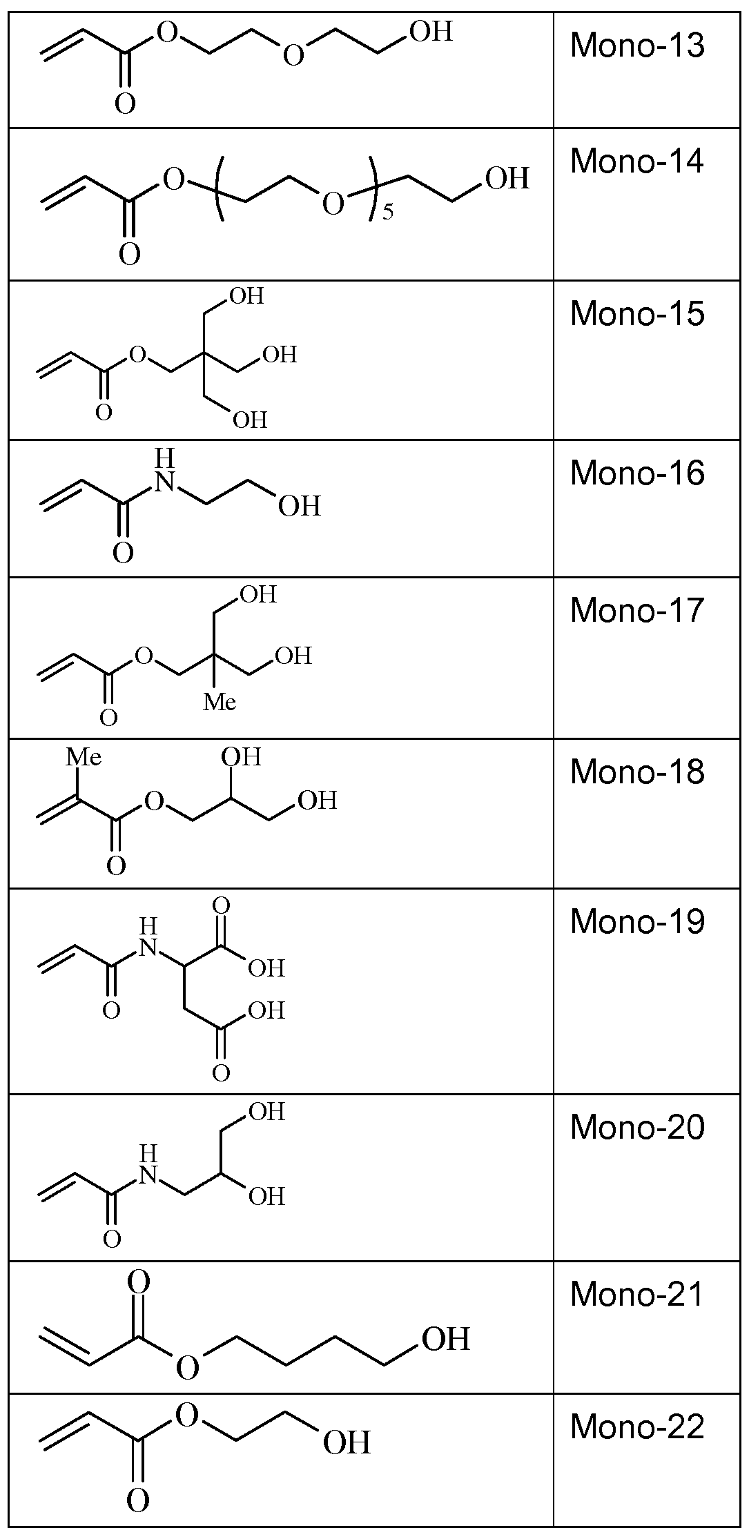
- Specific examples of hydrophilic monomers according to the present invention are given below, without being limited thereto.
- hydrophilic monomers described above may be used in combination with other monomers, as long as the protective layer obtained is hydrophilic and preferably removed by the ink and/or fountain during printing on a printing press.
- the second curable fluid may also comprise other ingredients such as an initiator, a co-initiator, a surfactant, a biocide, etc.
- an initiator such as an initiator, a co-initiator, a surfactant, a biocide, etc.
- a co-initiators, surfactants, biocides, a diluent, etc. may be used, as long as the protective layer obtained is hydrophilic and preferably soluble in the fountain solution used during printing.
- the second curable fluid preferably comprises an initiator.
- the amount of the initiator is preferably between 0.10 and 10 wt %, more preferably between 0.25 and 7.5 wt %, most preferably between 0.50 and 5 wt% relative to the total weight of the curable fluid.
- a photo-initiator which upon absorption of actinic radiation, preferably UV-radiation, forms high-energy species (for example radicals) inducing polymerization and optionally crosslinking of the monomers of the jetted droplets of the curable fluid.
- high-energy species for example radicals
- a combination of two or more photo-initiators may be used.
- a photo-initiator system comprising a photo-initiator and a co-initiator, may also be used.
- a suitable photo-initiator system comprises a photo-initiator, which upon absorption of actinic radiation forms free radicals by hydrogen abstraction or electron extraction from a second compound, the co-initiator. The co-initiator becomes the actual initiating free radical.
- the diluent is preferably a hydrophilic compound with low viscosity, for
- diluents are ethylene glycol, propylene glycol, water.
- the second curable fluid preferably does not contain a dye or a pigment.
- the support of the lithographic printing plate precursor has a hydrophilic
- the support is a grained and
- the surface roughness is often expressed as arithmetical mean center-line roughness Ra (ISO 4287/1 or DIN 4762) and may vary between 0.05 and 1.5 ⁇ .
- the aluminium substrate of the current invention has preferably an Ra value between 0.30 and 0.60 ⁇ , more preferably between 0.35 and 0.55 ⁇ and most preferably between 0.40 and 0.50 ⁇ .
- the lower limit of the Ra value is preferably 0.1 ⁇ . More details concerning the preferred Ra values of the surface of the grained and anodized aluminium support are described in EP-A 1356926.
- the microstructure as well as the thickness of the AI2O3 layer is determined by the anodizing step.
- the anodic weight (g/m 2 AI2O3 formed on the aluminium surface) varies between 1.0 and 8.0 g/m 2 .
- the anodic weight is preferably between 1.5 g/m 2 and 5.0 g/m 2 , more preferably between 2.5 g/m 2 and 4.0 g/m 2 and most preferably between 2.5 g/m 2 and 3.5 g/m 2 .
- the grained and anodized aluminium support may be subjected to a so-called post-anodic treatment to further improve the hydrophilic character of its surface.
- the aluminium support may be silicated by treating its surface with a solution including one or more alkali metal silicate
- a phosphate treatment may be applied which involves treating the aluminium oxide surface with a phosphate solution that may further contain an inorganic fluoride. Further, the aluminium oxide surface may be rinsed with a citric acid or citrate solution, gluconic acid, or tartaric acid. This treatment may be carried out at room temperature or may be carried out at a slightly elevated temperature of about 30 to 50°C.
- a further interesting treatment involves rinsing the aluminium oxide surface with a bicarbonate solution.
- the aluminium oxide surface may be treated with polyvinylphosphonic acid, polyvinylmethylphosphonic acid, phosphoric acid esters of polyvinyl alcohol, polyvinylsulphonic acid, polyvinylbenzenesulphonic acid, sulphuric acid esters of polyvinyl alcohol, acetals of polyvinyl alcohols formed by reaction with a sulphonated aliphatic aldehyde, polyacrylic acid or derivates such as GLASCOL E15TM commercially available from Ciba Speciality Chemicals.
- GLASCOL E15TM commercially available from Ciba Speciality Chemicals.
- the support is first treated with an aqueous
- silicate compound(s) as descibed above followed by a treatment of the support with an aqueous solution including a compound having a carboxylic acid group and/or a phosphonic acid group, or their salts.
- Particularly preferred silicate compounds are sodium or potassium orthosilicate and sodium or potassium metasilicate.
- Suitable examples of a compound with a carboxylic acid group and/or a phosphonic acid group and/or an ester or a salt thereof are polymers such as polyvinylphosphonic acid, polyvinylmethylphosphonic acid, phosphoric acid esters of polyvinyl alcohol, polyacrylic acid, polymethacrylic acid and a copolymer of acrylic acid and vinylphosphonic acid.
- a solution comprising polyvinylphosphonic acid or poly(meth)acrylic acid is highly preferred.
- the support can also be a flexible support, which may be provided with a hydrophilic layer.
- the flexible support is e.g. paper, plastic film or aluminium.
- Preferred examples of plastic film are polyethylene terephthalate film, polyethylene naphthalate film, cellulose acetate film, polystyrene film, polycarbonate film, etc.
- the plastic film support may be opaque or
- the hydrophilic layer is preferably a cross-linked hydrophilic layer obtained from a hydrophilic binder cross-linked with a hardening agent such as formaldehyde, glyoxal, polyisocyanate or a hydrolyzed tetra-alkylorthosilicate. The latter is particularly preferred.
- the thickness of the hydrophilic layer may vary in the range of 0.2 to 25 ⁇ and is preferably 1.0 to 10 ⁇ . More details of preferred embodiments of the base layer can be found in e.g.
- the hydrophilic surface of the support is preferably provided with a surfactant to improve the resolution of the printing plate obtained by the method of the present invention. A higher resolution may be obtained when the spreading of the droplets of the first curable fluid on the hydrophilic surface is
- Preferred surfactants are fluorosurfactants, for example the Zonyl® surfactants from Dupont. Also preferred are the more environmently friendly Tivida® fluorosurfactants from Merck.
- the amount of fluorosurfactants on the support surface is preferably between 0.005 and 0.5 g/m 2 , more preferably between 0.01 and 0.1 g/m 2 , most preferably between 0.02 and 0.06 g/m 2 .
- a particular preferred lithographic support is a grained and anodized
- aluminium support as described above treated with an aqueous solution including one or more silicate compound(s), and of which the surface is provided with a fluorosurfactant.
- FIG. 1 An embodiment of a flat bed printing device is shown in Figure 1 while an embodiment of a drum based printing device is shown in Figure 2.
- a lithographic support is provided on a flat bed (40). Droplets of a first and a second curable fluid are jetted from respectively a first (10) and a second (20) print head on the hydrophilic support.
- the print heads typically scan back and forth in a transversal direction (x- direction) across a moving lithographic support (y-direction). Such bidirectional printing is referred to as multi-pass printing.
- Another preferred printing method is the so-called single-pass printing
- a lithographic support is mounted on a cylindrical drum (50). While the lithographic support rotates in the x- direction, the print heads jetting a first curable fluid (10) and a second curable fluid (20) are moving in the y-direction.
- the print heads are positioned as close as possible to the surface of the lithographic support.
- the distance between the print heads and the surface of the lithographic support is preferably less than 3 mm, more preferably less than 2 mm, most preferably less than 1 mm.
- the thickness of a lithographic support is typically between 0.1 and 0.5 mm with a tolerance on the thickness of ⁇ 0.015 mm. As the distance between the printhead and the surface of the lithographic support may influence the dot placement accuracy, it may be advantageous to measure the thickness of a lithographic support and adapting the distance between the printhead and the surface of the lithographic support based on the measurement of the thickness of the lithographic support.
- the distance between a stationary printhead and the surface of a lithographic support mounted on the printing device may also vary over the whole lithographic support, due to for example waviness of the support, or other irregularities in the surface of the support. Therefore it may also be
- the inkjet computer-to-plate printing device has holding down means, such as a vacuum chamber under the printing support, to hold down the lithographic support in a so-called hold-down zone, for example by vacuum.
- the lithographic support is hold down against the printing support by independent working holding down means such as a plurality of vacuum chambers under the printing support which are independently controlled to enhance the vacuum pressure on the printing support so that more than one hold down zones are generated on the printing support.
- independent working holding down means such as a plurality of vacuum chambers under the printing support which are independently controlled to enhance the vacuum pressure on the printing support so that more than one hold down zones are generated on the printing support.
- the holding down of the lithographic support enhances the drop placement of the jetted droplets and position accuracy of the lithographic image which gives a better alignment and colour- on-colour registration when printing the colour digital image with the prepared lithographic printing plates on an offset press.
- Both the first and the second curable fluid may be jetted by one or more print heads ejecting small droplets in a controlled manner through nozzles onto the lithographic support, which is moving relative to the print head(s).
- a preferred print head for the inkjet printing system is a piezoelectric head.
- Piezoelectric inkjet printing is based on the movement of a piezoelectric ceramic transducer when a voltage is applied thereto.
- the application of a voltage changes the shape of the piezoelectric ceramic transducer in the print head creating a void, which is then filled with ink.
- the ceramic expands to its original shape, ejecting a drop of ink from the print head.
- the inkjet printing method according to the present invention is not restricted to piezoelectric inkjet printing.
- Other inkjet print heads can be used and include various types, such as the continuous printing type. [076] To obtain a sufficient resolution on the printing plate, for example 1200 or
- preferred print heads eject droplets having a volume ⁇ 15 pi, more preferably ⁇ 10 pi, most preferably ⁇ 5 pi, particularly preferred ⁇ 3 pi.
- a multi-drop piezoelectric inkjet print head is a multi-drop piezoelectric inkjet print head.
- a multi-drop piezoelectric print head also called a grayscale piezoelectric print head, such as the Konica MinoltaTM KM1024i, is capable of jetting droplets in a plurality of volumes, to improve the quality of the lithographic images on the lithographic supports.
- a throughflow piezoelectric inkjet print head is a print head wherein a continuous flow of liquid is circulating through the liquid channels of the print head to avoid agglomerations in the liquid which may cause disturbing effects in the flow and bad drop placements. Avoiding bad drop placements by using throughflow piezoelectric inkjet print heads may improve the quality of the lithographic images on the lithographic supports. Another advantage of using such throughflow print heads is a higher viscosity limit of the curable fluids to be jetted, widening the scope of compositional variations of the fluids.
- Two different print heads may be used for the first and the second curable fluid.
- the droplets of the second curable fluid may be larger than those of the first curable fluid.
- the droplets may even be higher than 15 pi.
- the first and the second curable fluids are preferably cured by exposure to actinic radiation, preferably to ultraviolet radiation.
- the curing means may be arranged in combination with the print heads of the printing device, travelling therewith so that the curing radiation is applied very shortly after jetting. Such rapid curing is sometimes referred to as " pin curing" and used for enhancing image quality by controlling the dot size.
- Preferably such curing means consists of one or more UV LEDs. In such an arrangement, it can be difficult to provide other types of curing means that are small enough to be connected to and travelling with the printhead.
- a static fixed radiation source may be employed, e.g. a UV bulb, connected to the printhead by means of flexible radiation conductive means such as a fibre optic bundle or an internally reflective flexible tube.
- the actinic radiation may be supplied from a fixed source to the radiation head by an arrangement of mirrors including a mirror on the printhead.
- the source of radiation may also be an elongated radiation source extending transversely across the substrate to be cured (curing means 30 in Figure 1 and 2). It may be adjacent the transverse path of the print head so that the subsequent rows of images formed by the print head are passed, stepwise or continually, beneath that radiation source.
- Both curing means i.e. a curing means travelling with the print heads and an elongated radiation source may be combined.
- a radiation source such as a high or low pressure mercury lamp, a cold cathode tube, a black light, an ultraviolet LED, an ultraviolet laser, and a flash light.
- the preferred source is one exhibiting a relatively long wavelength UV-contribution having a dominant wavelength of 300-400 nm.
- a UV-A light source is preferred due to the reduced light scattering therewith resulting in more efficient interior curing.
- UV radiation is generally classed as UV-A, UV-B, and UV-C as follows:
- UV-A 400 nm to 320 nm
- UV-C 290 nm to 100 nm.
- the inkjet printing device contains one or more UV LEDs with a wavelength larger than 360 nm, preferably one or more UV LEDs with a wavelength larger than 380 nm, and most preferably UV LEDs with a wavelength of about 395 nm.
- the first UV-source can be selected to be rich in UV-C, in particular in the range of 260 nm-200 nm.
- the second UV-source can then be rich in UV-A, e.g. a gallium-doped lamp, or a different lamp high in both UV-A and UV-B.
- the use of two UV-sources has been found to have advantages e.g. enabling a fast curing speed and a high curing degree.
- the printing device often includes one or more oxygen depletion units.
- the oxygen depletion units place a blanket of nitrogen or other relatively inert gas (e.g. CO2), with adjustable position and adjustable inert gas concentration, in order to reduce the oxygen concentration in the curing environment. Residual oxygen levels are usually maintained as low as 200 ppm, but are generally in the range of 200 ppm to 1200 ppm.
- Curing can be " partial” or “ full” .
- the terms “partial curing” and “full curing” refer to the degree of curing, i.e. the percentage of converted functional groups, and may be determined by, for example, RT-FTIR (Real- Time Fourier Transform Infa-Red Spectroscopy) which is a method well known to the one skilled in the art of curable formulations.
- Partial curing is defined as a degree of curing wherein at least 5 %, preferably 10 %, of the functional groups in the coated formulation or the fluid droplet is converted.
- Full curing is defined as a degree of curing wherein the increase in the percentage of converted functional groups with increased exposure to radiation (time and/or dose) is negligible.
- Full curing corresponds with a conversion percentage that is within 10 %, preferably 5 %, from the maximum conversion percentage. The maximum conversion percentage is typically determined by the horizontal asymptote in a graph representing the percentage conversion versus curing energy or cu
- hydrophilic protective layer formed by a cured second curable fluid is preferably removed by or soluble in the fountain used during printing, it may be advantageous to partially cure the jetted droplets of the second curable fluid.
- ACMO N-acryloylmorpholine from Rahn AG.
- HEA 2-hydroxyethylacrylate from BASF.
- MAES is mono-2-acryloxy-ethyl succinate from Aldrich.
- PEA is polyethyleneoxide monoacrylate from Cognis.
- TPO-L is trimethylbenzoylethoxyphenylphosphine from BASF
- HBA is 4-hydroxybutylacrylate from Nippon Kasei Chemical Co.
- MA is methacrylic acid from Akros Chimica.
- BYK333 is a surfactant from BYK Additives&lnstruments
- Zonyl FSA is a fluorosurfactant from Dupont.
- Rheocalc32 Version 2.6 Software, was used to measure the dynamic viscosity of each gum sample. Rheocalc was programmed with the following settings:
- the program was designed for viscosities between 6-12 mPa-s, the optimal range for jettability in a piezoelectric inkjet printing head. In cases where the viscosity was lower than 6 mPa-s, SSN was increased. SSN was lowered if the viscosity was higher than 12 mPa-s. Viscosity measurements were performed at a temperature of 45°C, to emulate the average temperature of a print head.
- a 0.3 mm thick aluminium foil was degreased by spraying its surface with an aqueous solution containing 34 g/l NaOH at 70°C for 6 seconds followed by rinsing it with demineralised water for 3.6 seconds.
- the foil was then electrochemically grained during 8 seconds using an alternating current in an aqueous solution containing 15 g/l HCI, 15 g/l SO 4 2" ions and 5 g/l Al 3+ ions at a temperature of 37°C and a current density of about 100 A/dm 2 (charge density of about 800 C/dm 2 ).
- the aluminium foil was desmutted by etching with an aqueous solution containing 6.5 g/l of sodium hydroxide at 35°C for 5 seconds and rinsed with demineralised water for 4 seconds.
- the foil was subsequently subjected to anodic oxidation during 10 seconds in an aqueous solution containing 145 g/l of sulfuric acid at a temperature of 57°C and an anodic charge of 250 C/dm 2 , then washed with demineralised water for 7 seconds and dried at 120°C for 7 seconds.
- the above described support was then silicated by spraying a sodium silicate solution (25 g/l sodium silicate in water) onto it for 4 seconds at 70°C, followed by a rinsing step with demineralised water for 3.5 seconds and a drying step at 120°C for 7 seconds.
- a sodium silicate solution 25 g/l sodium silicate in water
- the second curable fluids FL-01 to FL-06 were prepared by mixing the
- TPO-L 1.0 2.0 2.0 2.0 1.0 1.0
- PET polyethyleneterephthalate
- Both were then inserted into a quartz box under nitrogen atmosphere.
- the box was then exposed to UV-A radiation for seven seconds with the use of eight Philips ACTINIC BL 20 W UV-A light bulbs. In the span of seven seconds, each lamp emits approximately 0.006 W/cm 2 .
- the samples were then taken out of the box and run over with a cotton swab to ensure the coatings were fully cured, i.e. substantially no material was removed by the cotton swab.
- a print test was conducted with the cured hydrophilic layers HL-01 to HL-06 coated on the lithographic support to evaluate their hydrophilicity and solubility on a printing press. Furthermore it is important to evaluate if the UV- cured hydrophilic layer has an adverse effects on the printing process such as increased start-up, stickiness of the paper, etc. Up to 250 prints were done with a Heidelberg GTO 52 sheetfed press (using K+E 800 ink from Flint; 2 wt% FS 404 fountain from Agfa Graphics; and 90 g paper from Amber Offset).
Landscapes
- Chemical & Material Sciences (AREA)
- Engineering & Computer Science (AREA)
- Life Sciences & Earth Sciences (AREA)
- Materials Engineering (AREA)
- Wood Science & Technology (AREA)
- Organic Chemistry (AREA)
- Physics & Mathematics (AREA)
- Manufacturing & Machinery (AREA)
- Optics & Photonics (AREA)
- General Physics & Mathematics (AREA)
- Chemical Kinetics & Catalysis (AREA)
- Printing Plates And Materials Therefor (AREA)
- Manufacture Or Reproduction Of Printing Formes (AREA)
- Materials For Photolithography (AREA)
- Ink Jet Recording Methods And Recording Media Thereof (AREA)
- Printing Methods (AREA)
Abstract
Description



Claims
Priority Applications (3)
| Application Number | Priority Date | Filing Date | Title |
|---|---|---|---|
| JP2017522931A JP2018500196A (en) | 2014-11-06 | 2015-11-02 | Method for producing a precursor of a lithographic printing plate |
| US15/524,821 US10569528B2 (en) | 2014-11-06 | 2015-11-02 | Method for preparing a lithographic printing plate precursor |
| CN201580060413.1A CN107635774B (en) | 2014-11-06 | 2015-11-02 | Method for preparing lithographic printing plate precursor |
Applications Claiming Priority (2)
| Application Number | Priority Date | Filing Date | Title |
|---|---|---|---|
| EP14192061.1A EP3017944B1 (en) | 2014-11-06 | 2014-11-06 | Method for preparing a lithographic printing plate precursor |
| EP14192061.1 | 2014-11-06 |
Publications (1)
| Publication Number | Publication Date |
|---|---|
| WO2016071255A1 true WO2016071255A1 (en) | 2016-05-12 |
Family
ID=51870889
Family Applications (1)
| Application Number | Title | Priority Date | Filing Date |
|---|---|---|---|
| PCT/EP2015/075389 Ceased WO2016071255A1 (en) | 2014-11-06 | 2015-11-02 | Method for preparing a printing plate precursor |
Country Status (7)
| Country | Link |
|---|---|
| US (1) | US10569528B2 (en) |
| EP (1) | EP3017944B1 (en) |
| JP (1) | JP2018500196A (en) |
| CN (1) | CN107635774B (en) |
| ES (1) | ES2642814T3 (en) |
| PL (1) | PL3017944T3 (en) |
| WO (1) | WO2016071255A1 (en) |
Families Citing this family (4)
| Publication number | Priority date | Publication date | Assignee | Title |
|---|---|---|---|---|
| EP3587112B1 (en) * | 2018-06-21 | 2024-04-03 | Eco3 Bv | A lithographic printing plate precursor |
| CN109454973B (en) * | 2018-11-15 | 2021-01-12 | 安徽原上草节能环保科技有限公司 | Method for processing flexographic printing plate |
| DE102021123590A1 (en) * | 2020-10-08 | 2022-04-14 | Heidelberger Druckmaschinen Aktiengesellschaft | Process for curing printed coatings using electron beams |
| EP4443243A1 (en) * | 2023-04-05 | 2024-10-09 | Esko-Graphics Imaging GmbH | Process and system for minimizing plate deformation in the solvent minimized manufacture of a printing plate |
Citations (4)
| Publication number | Priority date | Publication date | Assignee | Title |
|---|---|---|---|---|
| EP1266750A1 (en) * | 2001-06-15 | 2002-12-18 | Agfa-Gevaert | Method for preparation of a lithographic printing plate |
| EP1800890A1 (en) * | 2005-12-20 | 2007-06-27 | Agfa Graphics N.V. | Method for gumming a lithographic printing plate |
| EP1935652A1 (en) * | 2006-12-21 | 2008-06-25 | Agfa Graphics N.V. | Inkjet Printing methods and ink sets |
| EP2033778A1 (en) * | 2007-09-10 | 2009-03-11 | Agfa Graphics N.V. | Method of making a flexographic printing sleeve forme |
Family Cites Families (20)
| Publication number | Priority date | Publication date | Assignee | Title |
|---|---|---|---|---|
| GB1084070A (en) | 1960-08-05 | 1967-09-20 | Kalle Ag | Process and material for the preparation of planographic printing plates |
| DE3126627A1 (en) | 1981-07-06 | 1983-01-20 | Hoechst Ag, 6000 Frankfurt | POLYVINYLMETHYLPHOSPHINIC ACID, METHOD FOR THE PRODUCTION THEREOF AND THEIR USE |
| US4847359A (en) | 1986-06-30 | 1989-07-11 | Ciba-Geigy Corporation | Diamino-9,10-dihydroanthracenes and polyamide acid (esters) and polyimides derived therefrom |
| DE3715791A1 (en) | 1987-05-12 | 1988-11-24 | Hoechst Ag | PRINT PLATE CARRIERS AND METHOD AND DEVICE FOR THE PRODUCTION THEREOF |
| DE3717654A1 (en) | 1987-05-26 | 1988-12-08 | Hoechst Ag | METHOD FOR ELECTROCHEMICALLY Roughening ALUMINUM FOR PRINTING PLATE CARRIERS |
| DE4001466A1 (en) | 1990-01-19 | 1991-07-25 | Hoechst Ag | Electrochemical roughening of aluminium for printing plate mfr. - using combination of mechanical and electrochemical roughening before and/or after main electrochemical roughening stage |
| DE4134143A1 (en) | 1991-10-16 | 1993-06-24 | Hoechst Ag | METHOD FOR MANUFACTURING FLAT PRESSURE FORMS AND FLAT PRINTING MAKES PRODUCED THEREOF |
| GB9326150D0 (en) | 1993-12-22 | 1994-02-23 | Alcan Int Ltd | Electrochemical roughening method |
| DE4417907A1 (en) | 1994-05-21 | 1995-11-23 | Hoechst Ag | Process for the aftertreatment of plate, foil or strip material, supports of such material and its use for offset printing plates |
| DE4423140A1 (en) | 1994-07-01 | 1996-01-04 | Hoechst Ag | Hydrophilized carrier material and recording material produced therewith |
| EP1342568B1 (en) | 2002-03-06 | 2005-10-12 | Agfa-Gevaert N.V. | Method of developing a heat-sensitive lithographic printing plate precursor with a gum solution |
| EP1356926B1 (en) | 2002-04-26 | 2008-01-16 | Agfa Graphics N.V. | Negative-working thermal lithographic printing plate precursor comprising a smooth aluminum support. |
| JP2007538279A (en) | 2004-05-19 | 2007-12-27 | アグファ・ゲヴェルト・ナームロゼ・ベンノートチャップ | Method for producing photosensitive polymer printing plate |
| ATE431246T1 (en) | 2004-09-16 | 2009-05-15 | Agfa Graphics Nv | METHOD FOR PRODUCING A FLEXO PRINTING PLATE |
| US20060188813A1 (en) * | 2005-02-22 | 2006-08-24 | Fuji Photo Film Co., Ltd. | Hydrophilic film, and planographic printing material, stain-preventative member and defogging member using the same |
| JP2007185903A (en) * | 2006-01-16 | 2007-07-26 | Fujifilm Corp | Planographic printing plate making machine |
| EP2199082B1 (en) | 2008-12-19 | 2013-09-04 | Agfa Graphics N.V. | Method for making flexographic printing masters |
| US20100215865A1 (en) | 2009-02-26 | 2010-08-26 | Xerox Corporation | Preparation of flexographic printing masters using an additive process |
| JP5514781B2 (en) * | 2011-08-31 | 2014-06-04 | 富士フイルム株式会社 | Planographic printing plate precursor and method for producing a lithographic printing plate using the same |
| CN103358639B (en) * | 2013-07-15 | 2016-02-03 | 广东富盛新材料股份有限公司 | Air brushing sheet material and manufacture method thereof |
-
2014
- 2014-11-06 EP EP14192061.1A patent/EP3017944B1/en not_active Not-in-force
- 2014-11-06 ES ES14192061.1T patent/ES2642814T3/en active Active
- 2014-11-06 PL PL14192061T patent/PL3017944T3/en unknown
-
2015
- 2015-11-02 JP JP2017522931A patent/JP2018500196A/en active Pending
- 2015-11-02 US US15/524,821 patent/US10569528B2/en not_active Expired - Fee Related
- 2015-11-02 WO PCT/EP2015/075389 patent/WO2016071255A1/en not_active Ceased
- 2015-11-02 CN CN201580060413.1A patent/CN107635774B/en not_active Expired - Fee Related
Patent Citations (4)
| Publication number | Priority date | Publication date | Assignee | Title |
|---|---|---|---|---|
| EP1266750A1 (en) * | 2001-06-15 | 2002-12-18 | Agfa-Gevaert | Method for preparation of a lithographic printing plate |
| EP1800890A1 (en) * | 2005-12-20 | 2007-06-27 | Agfa Graphics N.V. | Method for gumming a lithographic printing plate |
| EP1935652A1 (en) * | 2006-12-21 | 2008-06-25 | Agfa Graphics N.V. | Inkjet Printing methods and ink sets |
| EP2033778A1 (en) * | 2007-09-10 | 2009-03-11 | Agfa Graphics N.V. | Method of making a flexographic printing sleeve forme |
Also Published As
| Publication number | Publication date |
|---|---|
| JP2018500196A (en) | 2018-01-11 |
| US10569528B2 (en) | 2020-02-25 |
| PL3017944T3 (en) | 2017-11-30 |
| CN107635774B (en) | 2020-09-11 |
| CN107635774A (en) | 2018-01-26 |
| US20170313052A1 (en) | 2017-11-02 |
| ES2642814T3 (en) | 2017-11-20 |
| EP3017944A1 (en) | 2016-05-11 |
| EP3017944B1 (en) | 2017-07-19 |
Similar Documents
| Publication | Publication Date | Title |
|---|---|---|
| CN114423613B (en) | Lithographic printing plate precursors and methods of use | |
| CN111867838A (en) | Lithographic printing plate precursors | |
| EP3057794B1 (en) | Method for providing lithographic printing plates | |
| BRPI0616830B1 (en) | METHOD FOR THE PRODUCTION OF A PLATE FOR LITHOGRAPHIC PRINTING | |
| US10569528B2 (en) | Method for preparing a lithographic printing plate precursor | |
| US20090186201A1 (en) | Plate making method and planographic printing plate | |
| CN101652251A (en) | Method for making a lithographic printing plate precursor | |
| CN105392634A (en) | Precursor of lithographic printing plate and plate-making method thereof | |
| EP3441223B1 (en) | A lithographic printing plate precursor | |
| US20110139026A1 (en) | Ink-jet platemaking method | |
| US11635693B2 (en) | Lithographic printing plate precursor | |
| EP3215365B1 (en) | A sustainable lithographic printing plate | |
| WO2021132610A1 (en) | Lithographic printing plate manufacturing method and lithographic printing method | |
| JP4806222B2 (en) | Planographic printing plate manufacturing method | |
| JP4806221B2 (en) | Planographic printing plate manufacturing method | |
| CN117098665A (en) | Lithographic printing plate precursors and methods of use | |
| JP2007230185A (en) | Treatment liquid and processing method for lithographic printing plate |
Legal Events
| Date | Code | Title | Description |
|---|---|---|---|
| 121 | Ep: the epo has been informed by wipo that ep was designated in this application |
Ref document number: 15788034 Country of ref document: EP Kind code of ref document: A1 |
|
| ENP | Entry into the national phase |
Ref document number: 2017522931 Country of ref document: JP Kind code of ref document: A |
|
| WWE | Wipo information: entry into national phase |
Ref document number: 15524821 Country of ref document: US |
|
| NENP | Non-entry into the national phase |
Ref country code: DE |
|
| 122 | Ep: pct application non-entry in european phase |
Ref document number: 15788034 Country of ref document: EP Kind code of ref document: A1 |