WO2016070842A1 - Container number recognition method and system - Google Patents
Container number recognition method and system Download PDFInfo
- Publication number
- WO2016070842A1 WO2016070842A1 PCT/CN2015/093986 CN2015093986W WO2016070842A1 WO 2016070842 A1 WO2016070842 A1 WO 2016070842A1 CN 2015093986 W CN2015093986 W CN 2015093986W WO 2016070842 A1 WO2016070842 A1 WO 2016070842A1
- Authority
- WO
- WIPO (PCT)
- Prior art keywords
- image acquisition
- container
- acquisition unit
- image
- sensors
- Prior art date
Links
Images


Classifications
-
- G—PHYSICS
- G06—COMPUTING; CALCULATING OR COUNTING
- G06V—IMAGE OR VIDEO RECOGNITION OR UNDERSTANDING
- G06V10/00—Arrangements for image or video recognition or understanding
- G06V10/10—Image acquisition
- G06V10/12—Details of acquisition arrangements; Constructional details thereof
- G06V10/14—Optical characteristics of the device performing the acquisition or on the illumination arrangements
- G06V10/147—Details of sensors, e.g. sensor lenses
-
- G—PHYSICS
- G06—COMPUTING; CALCULATING OR COUNTING
- G06K—GRAPHICAL DATA READING; PRESENTATION OF DATA; RECORD CARRIERS; HANDLING RECORD CARRIERS
- G06K7/00—Methods or arrangements for sensing record carriers, e.g. for reading patterns
-
- G—PHYSICS
- G06—COMPUTING; CALCULATING OR COUNTING
- G06V—IMAGE OR VIDEO RECOGNITION OR UNDERSTANDING
- G06V20/00—Scenes; Scene-specific elements
- G06V20/60—Type of objects
- G06V20/62—Text, e.g. of license plates, overlay texts or captions on TV images
- G06V20/63—Scene text, e.g. street names
-
- H—ELECTRICITY
- H04—ELECTRIC COMMUNICATION TECHNIQUE
- H04N—PICTORIAL COMMUNICATION, e.g. TELEVISION
- H04N23/00—Cameras or camera modules comprising electronic image sensors; Control thereof
- H04N23/90—Arrangement of cameras or camera modules, e.g. multiple cameras in TV studios or sports stadiums
-
- H—ELECTRICITY
- H04—ELECTRIC COMMUNICATION TECHNIQUE
- H04N—PICTORIAL COMMUNICATION, e.g. TELEVISION
- H04N7/00—Television systems
- H04N7/18—Closed-circuit television [CCTV] systems, i.e. systems in which the video signal is not broadcast
- H04N7/181—Closed-circuit television [CCTV] systems, i.e. systems in which the video signal is not broadcast for receiving images from a plurality of remote sources
-
- H—ELECTRICITY
- H04—ELECTRIC COMMUNICATION TECHNIQUE
- H04N—PICTORIAL COMMUNICATION, e.g. TELEVISION
- H04N7/00—Television systems
- H04N7/18—Closed-circuit television [CCTV] systems, i.e. systems in which the video signal is not broadcast
- H04N7/188—Capturing isolated or intermittent images triggered by the occurrence of a predetermined event, e.g. an object reaching a predetermined position
-
- G—PHYSICS
- G06—COMPUTING; CALCULATING OR COUNTING
- G06V—IMAGE OR VIDEO RECOGNITION OR UNDERSTANDING
- G06V2201/00—Indexing scheme relating to image or video recognition or understanding
- G06V2201/06—Recognition of objects for industrial automation
-
- G—PHYSICS
- G06—COMPUTING; CALCULATING OR COUNTING
- G06V—IMAGE OR VIDEO RECOGNITION OR UNDERSTANDING
- G06V30/00—Character recognition; Recognising digital ink; Document-oriented image-based pattern recognition
- G06V30/10—Character recognition
Definitions
- Embodiments of the present invention relate to container detection, and more particularly to a container number identification method and a container number identification system.
- the existing container number acquisition and identification system has a hand-held device that manually acquires a container number image and extracts a number character, and also has a device that automatically acquires a container number image and extracts a number character on a one-way channel of the container truck.
- the container number is automatically obtained only by performing one time on one side of the container.
- Image actions ie, one shot
- the present invention has been proposed to prevent or reduce the problem that the container number on the surface corresponding to the image acquisition unit is fouled or the container number is difficult to read due to occlusion or fragmentation.
- a container number identification method comprising the steps of:
- the image acquisition device comprising a trigger unit and a plurality of image acquisition units, the plurality of image acquisition units being adapted to respectively acquire container number images on a plurality of faces of the container passing through the channel;
- the container number is identified based at least on images or data from the at least two image acquisition units regarding the container number.
- At least two image acquisition units of the plurality of image acquisition units respectively acquire container number images on at least two of the plurality of faces based on signals of the trigger unit at different times, wherein: the distance between the projections of the at least two image acquisition units in the direction of movement of the container relative to the channel is less than the length of the container.
- a position of each of the at least two image acquisition units is set such that each of the at least two image acquisition units is in two opposite movement directions of the container with respect to the channel
- an image acquisition unit acquires the container number image on the corresponding surface
- the relative position with respect to the corresponding surface of the container is fixed.
- a container number identification system comprising:
- An image acquisition device arranged along a passage through which the container passes, the image acquisition device comprising a trigger unit and a plurality of image acquisition units, at least two of the plurality of image acquisition units being adapted to be separately acquired based on signals of the trigger unit a container number image on at least two of the plurality of faces of the container passing through the passage;
- a number identifying device that identifies the container number based on at least images or data from the at least two image acquisition units regarding the container number
- the distance between the projections of the at least two image acquisition units in the moving direction of the container with respect to the channel is smaller than the length of the container.
- each of the at least two image acquisition units acquires the container number image on the corresponding face in two opposite moving directions with respect to the channel The position is fixed.
- FIG. 1 is a flow chart of a container number acquisition method according to an embodiment of the present invention.
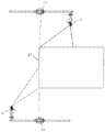
- FIG. 2 is a schematic plan view showing a structural layout of a container number acquisition system according to a first exemplary embodiment of the present invention
- 3a and 3b are schematic diagrams showing a process of acquiring a container number image on a plurality of sides of a container according to the container number acquisition system of FIG. 2;
- FIG. 4 is a schematic plan view showing a structural layout of a container number acquisition system according to a second exemplary embodiment of the present invention.
- 5a and 5b are schematic diagrams showing a process of acquiring a container number image on a plurality of sides of a container according to the container number acquisition system of FIG. 4;
- FIG. 6 is a schematic plan view showing a structural layout of a container number acquisition system according to a third exemplary embodiment of the present invention.
- FIG. 7a-d are schematic diagrams showing a process of acquiring a container number image on a plurality of sides of a container according to the container number acquisition system of FIG. 6;
- Figure 8 is a schematic plan view showing a structural layout of a container number acquisition system according to a fourth exemplary embodiment of the present invention.
- FIG. 9a-d are schematic diagrams showing a process of acquiring an image of a container number on a plurality of sides of a container according to the container number acquisition system of FIG. 8;
- FIG. 10 is a schematic plan view showing a structural layout of a container number acquisition system according to a fifth exemplary embodiment of the present invention.
- FIG. 11a and 11b are schematic diagrams showing a process of acquiring a container number image on a plurality of sides of a container according to the container number acquisition system of FIG. 10;
- Figure 12 is a schematic plan view showing a structural layout of a container number acquisition system according to a sixth exemplary embodiment of the present invention.
- FIG. 13a-c are schematic diagrams showing a process of acquiring a container number image on a plurality of sides of a container according to the container number acquisition system of FIG. 12;
- Figure 14 is a schematic plan view showing a structural layout of a container number acquisition system according to a seventh exemplary embodiment of the present invention.
- 15a-c are schematic diagrams of processes for obtaining a container number image on a plurality of sides of a container according to the container number acquisition system of FIG. 14;
- FIG. 16a is a schematic diagram of a process of acquiring a container number image on a plurality of faces of a container according to an eighth exemplary embodiment of the present invention
- FIG. 16b is a plurality of acquisition containers according to a modification of the eighth exemplary embodiment of the present invention. Schematic diagram of the process of the container number image on the surface.
- Figure 17 is a schematic plan view showing a structural layout of a container number acquisition system according to a ninth exemplary embodiment of the present invention.
- 18a and 18b are schematic diagrams showing a process of acquiring a container number image on a plurality of sides of a container according to the container number acquisition system of FIG. 17;
- Figure 19 is a schematic plan view showing a structural layout of a container number acquisition system according to a tenth exemplary embodiment of the present invention.
- Figure 20 is a schematic view showing the process of capturing the state of the container number acquisition system of Figure 19, and the upper part of Figure 20 shows the relative movement between the container and the container number acquisition system and the container number.
- the capture timing of the code acquisition system, the lower part of FIG. 20 shows a schematic diagram of the capture timing and state transition relationship of the container number acquisition system of FIG. 19;
- FIG. 21 is a schematic diagram showing another process of capturing the state of the container number acquisition system of FIG. 19.
- the upper part of FIG. 21 shows the relative movement between the container and the container number acquisition system and the capture timing of the container number acquisition system.
- the lower part of 21 shows a schematic diagram of the snap timing and state transition relationship of the container number acquisition system in FIG. 19;
- Figure 22 is a schematic plan view showing a structural layout of a container number acquisition system according to an eleventh exemplary embodiment of the present invention.
- FIG. 23 is a schematic diagram showing the process of capturing the state of the container number acquisition system of FIG. 22, and the upper part of FIG. 23 shows the relative movement between the container and the container number acquisition system and the capture timing of the container number acquisition system, FIG. The lower part shows a schematic diagram of the snap timing and state transition relationship of the container number acquisition system in FIG. 22;
- Figure 24 is a schematic diagram showing another process of capturing the state of the container number acquisition system of Figure 22, the upper part of Figure 24 showing the relative movement between the container and the container number acquisition system and the capture timing of the container number acquisition system, The lower part of 24 shows a schematic diagram of the snap timing and state transition relationship of the container number acquisition system in Fig. 22.
- FIG. 1 is a flow chart of a container number acquisition method in accordance with an embodiment of the present invention. As shown in FIG. 1, the container number identification method includes the following steps:
- S1 setting an image acquisition device on a channel along which the container travels, the image acquisition device comprising a trigger unit and a plurality of image acquisition units, the plurality of image acquisition units being adapted to respectively acquire a plurality of faces of the container traveling along the channel Container number image on;
- S2 acquiring, by the at least two image acquiring units, respectively, a container number image on at least two of the plurality of faces based on a signal of the trigger unit;
- S3 Identify the container number based on at least images or data from the at least two image acquisition units regarding the container number.
- the container number image of at least two sides of the container is acquired by the image acquisition unit based on the trigger signal of the trigger unit, and the container number character is extracted from the acquired one or more images by using a character recognition algorithm.
- the image of the plurality of numbers captured by the image acquisition device in the same container is obtained by different angles of the container, and the character recognition algorithm separately extracts the recognition results, and then votes the results to obtain the most correct result.
- the container numbers on each side are the same. Even if the container number on one side cannot be completely identified due to fouling, occlusion or fragmentation, it can be identified by the complete container number on the other side.
- the container number identification on at least two sides such as the different parts of the numbers on the two sides, that is, the partial stain of the number on one side, and the corresponding part of the number on the other side is intact, Then, the corresponding portion of the number on the other side can be used to proxy the stained portion of the number on the one side to obtain the complete number), so that the container number can be accurately obtained when the container passes through the passage once. That is, obtaining a number image of more locations in the same container helps to improve the accuracy of the recognition result.
- the container number consists of the box main code, equipment identification code, box number and check code.
- the container number referred to herein includes at least one of a box master code, a device identification code, a box number, and a check code.
- the acquisition of the container number images on different planes may be performed at the same time according to the timing.
- the trigger unit generates a signal based on movement of the container relative to the channel, and at least two of the plurality of image acquisition units respectively acquire the plurality of faces based on signals of the trigger unit at different times An image of the container number on at least two of the faces.
- the distance between the at least two image acquisition units is smaller than the length of the container in the moving direction of the container with respect to the channel, and further, the at least two image acquisition units are in the moving direction of the container with respect to the channel
- the distance between projections is less than the length of a standard short container (20 feet, about 6 meters), and of course can be set to be less than the length of a long container (40 feet or 45 feet). Since the distance between the image capturing units in the relative moving direction is smaller than the length of the container, the length of the detecting passage can be set to be smaller than the length of the container, thereby saving the arrangement space.
- the passage through which the container passes may be a fixed detection passage, and the container transport device, such as a container truck, carries the container through the fixed passage, and the image acquisition device is arranged along the fixed passage;
- the passage through which the container passes may also be a passage provided or defined by the vehicle.
- At least the image acquisition device in the container number identification system is disposed on the carrier along the passage, the container is fixed, and the vehicle carrying image acquisition device Relative to the movement of the container, it provides or defines a passage for the container to pass, thereby obtaining an image of the container number on different sides of the container.
- the position of each of the at least two image acquisition units is set such that: at least two of the opposite movement directions of the container relative to the channel
- Each of the image acquisition units acquires a container number image on the corresponding surface with a relative position relative to the corresponding surface of the container.
- the image of the portion of the front A1 of the container having the container number is captured by the first image acquisition unit 11, and when the container A is, for example, When entering the channel from right to left in Fig. 5b, the image of the portion of the front A1 of the container having the container number is still captured by the first image acquisition unit 11, and, because in Fig. 5, the container A is left from Fig. 5a.
- the signal path based on the second group of sensors mentioned later is blocked, the first image acquisition unit 11 is triggered to perform one capture; when the container A enters the channel from right to left, for example, in FIG.
- the first image acquisition unit 11 is triggered to perform a snap.
- the first image acquisition unit 11 acquires the container number image on the front face A1 of the container A with respect to the relative position of the front face A1 of the container.
- the above description applies equally to the rear A2 of the container A and the two sides A3, A4.
- the present invention proposes a bidirectional adaptive container number acquisition method. That is, no matter which direction the container enters the channel relatively, the photo of the container spray number identification portion can be accurately obtained, so that the container number can be obtained. Based on the container number, the method of the present invention can discriminate the type and number of containers passing through the passage, as well as the size code and box type code of the container.
- the moving direction of the container relative to the channel is not limited, that is, the traveling direction of the container truck or the vehicle carrying the image acquiring device is not limited.
- FIGS. 3a and 3b are container numbers obtained on a plurality of sides of a container according to the container number acquisition system of FIG. A schematic diagram of the process of the image.
- the trigger unit includes a first group of sensors including a first signal transmitting portion 21a and a first signal receiving respectively located on both sides of the container perpendicular to the moving direction. Part 21b;
- the at least two image acquisition units include a first image acquisition unit 11 and a second image acquisition unit 12 adapted to respectively acquire container image images on the front and rear of the container;
- the step of "acquiring, by the at least two image acquisition units, respectively, the container number images on at least two of the plurality of faces based on the signals of the trigger unit at different times” comprises: in front of the container A as shown in FIG. 3a One side of A1 and rear A2 (front A1 in Fig. 3a) begins to occlude the first signal path of the first group of sensors (in Fig. 2, between the first signal transmitting portion 21a and the first signal receiving portion 21b) a dotted line), a corresponding image acquisition unit (the first image acquisition unit 11 in FIG. 3a) of the first image acquisition unit 11 and the second image acquisition unit 12 acquires a container number image on the one side; As shown in FIG.
- the first image acquisition unit is restored when the other side of the front A1 and the rear A2 of the container A (the rear A2 in FIG. 3b) exits to restore the first signal path of the first set of sensors. 11 and another image acquisition unit (the second image acquisition unit 12 in FIG. 3) corresponding to the second image acquisition unit 12 acquires the container number image on the other side.
- the midpoint of the connection between the first image acquiring unit 11 and the second image acquiring unit 12 is the first signal path. midpoint.
- the first and second image acquisition units are symmetrically arranged with respect to the midpoint.
- This symmetrical arrangement makes the snap timing symmetrical, so that the image acquisition units symmetrically arranged with each other can use the same set of correction parameters, reducing the workload of the character recognition algorithm for image correction.
- the images captured by the first image acquisition unit 11 and the second image acquisition unit 12 are consistent regardless of the shooting distance or the angle.
- the position of the captured character in the image and the character distortion caused by the use of the lens are also the same.
- the image algorithm For each deformed character, the image algorithm requires a set of correction parameters to correct the character image before identifying it.
- the correction parameters need to be performed one by one for the image acquisition units at different positions. If a symmetric layout is employed, we can find that the first image acquisition unit 11 and the second image acquisition unit 12 can use the correction parameters generated by one of the camera calibrations, thereby reducing the calibration work. Conversely, if a symmetrical layout is not used, the shooting angle and distance of each image acquisition unit are inconsistent, and it is necessary to correct each image acquisition unit. In addition, if the capture timing of the container is asymmetrical when passing through the channel in the forward and reverse directions, the focal length will be inconsistent during imaging, and the image acquisition unit needs to be automatically adjusted. When the container passes at a high speed, the auto focus adjustment may not be completed. Causes the image to be out of focus.
- the sensor type is not particularly limited as long as the position of the container in the passage can be accurately perceived.
- the sensor usually adopts a photoelectric switch, that is, the signal transmitting portion and the signal receiving portion are respectively a light emitting portion and a light receiving portion, and the signal path is correspondingly a beam line. Ultrasonic sensors, light curtains, ground coils, etc. can also be used for the sensor.
- the sensor may also be a scattering sensor, that is, no The signal transmitting portion is required only to sense whether the container truck arrives through the signal receiving portion, and accordingly, each group of sensors may include a signal receiving portion on the inner side of the channel.
- the occlusion or departure signal path indicates the interruption and recovery of the signal path between the two when the signal transmitting portion and the signal receiving portion are present at the same time, and indicates that the signal receiving portion is traveling due to the container when only the signal receiving portion exists Cannot receive a signal or resume receiving a signal.
- the photoelectric switch is taken as an example for description.
- the image acquisition unit is any image acquisition unit that can capture a container number image on the face of the container to generate a digital signal.
- the image acquisition unit is a digital camera, and the container number image is obtained by taking a picture.
- the image acquisition unit may also be a digital video camera, and the container number image may be extracted from the video stream of the camera and saved as an image.
- FIGS. 5a and 5b are container numbers obtained on a plurality of sides of a container according to the container number acquisition system of FIG. A schematic diagram of the process of the image.
- the trigger unit includes a second group of sensors and a third group of sensors spaced apart along a relative movement direction of the container with respect to the channel, the second group of sensors including two sides of the container perpendicular to the moving direction. a second signal transmitting portion 22a and a second signal receiving portion 22b, the third group of sensors including a third signal transmitting portion 23a and a third signal receiving portion 23b respectively located on both sides of the container in a moving direction; the at least two
- the image acquisition unit includes a first image acquisition unit 11 and a second image acquisition unit 12 adapted to respectively acquire the container number images on the front A1 and the rear A2 of the container A. As shown in FIG.
- the step of "acquiring, by the at least two image acquisition units, respectively, the container number images on at least two of the plurality of faces based on the signals of the trigger unit at different times" includes: in front of the container A When one of A1 and the latter A2 (front A1 in FIG. 5a) starts to occlude the second signal path of the second group of sensors, as shown in FIG. 5a, the first image acquisition unit 11 and the second image acquisition unit A corresponding one of the image acquisition units 12 (the first image acquisition unit 11 in Fig. 5a) acquires the container number image on the one side in the front A1 and the rear A2; and another in the front A1 and the rear A2 of the container A When one side (the rear A2 in FIG.
- FIGS. 7a-d are containers numbers obtained on a plurality of sides of a container according to the container number acquisition system of FIG. A schematic diagram of the process of the image.
- the at least two image acquisition units further include a third image acquisition unit 13 which is adapted to the example of FIGS. 4-5. Obtain a container number image on one side of the container (corresponding to the right side A3 in Figures 7a and 7b).
- the step of "acquiring, by the at least two image acquisition units, respectively, the container number images on at least two of the plurality of faces based on the signals of the triggering unit at different times" includes :
- the A corresponding one of the image acquisition unit 11 and the second image acquisition unit 12 acquires the container number image on the one side of the front A1 and the rear A2;
- the third image acquisition unit 13 acquires An image of the container number on the one side;
- the first image acquisition unit 11 and another image acquisition unit (the second image acquisition unit 12 in Fig. 7d) corresponding to the second image acquisition unit 12 acquires the container number image on the other side.
- the at least two image acquisition units further comprise a fourth image acquisition unit 14 adapted to acquire another side of the container (in the figure) 7a-c corresponding to the container number image on the left side A4); "the container number image of at least two of the plurality of faces is respectively acquired by the at least two image acquisition units based on the signals of the trigger unit at different times
- the step of between the step shown in FIG. 7b and the step shown in FIG. 7d further includes: starting on one side (the rear side A2 in FIG. 7) of the front A1 and the rear side A2 of the container A to resume the second When the second signal path of the sensor is grouped, as shown in FIG. 7c, the fourth image acquisition unit 14 acquires the container number image on the other side.
- the midpoint of the connection of the first image acquisition unit 11 and the second image acquisition unit 12 constitutes the third image acquisition unit 13 and the First The midpoint of the line connecting the four image acquisition units 14.
- This symmetrical arrangement makes the snap timing symmetrical, so that the image acquisition units symmetrically arranged with each other can use the same set of correction parameters, reducing the workload of the character recognition algorithm for image correction.
- the images captured by the first image acquiring unit 11 and the second image acquiring unit 12, and the third image acquiring unit 13 and the fourth image acquiring unit 14 are consistent in shooting distance and angle. of.
- the position of the captured character in the image and the character distortion caused by the use of the lens are also the same.
- the image algorithm For each deformed character, the image algorithm requires a set of correction parameters to correct the character image before identifying it.
- the correction parameters need to be performed one by one for the image acquisition units at different positions. If a symmetric layout is employed, we can find that the first image acquisition unit 11 and the second image acquisition unit 12 can use the correction parameters generated by one of the camera calibrations, and the third image acquisition unit 13 and the fourth image acquisition unit 14 Calibration parameters generated by one of the camera calibrations can be used, reducing calibration effort. Conversely, if a symmetrical layout is not used, the shooting angle and distance of each image acquisition unit are inconsistent, and it is necessary to correct each image acquisition unit.
- the capture timing of the container is asymmetrical when passing through the channel in the forward and reverse directions, the focal length will be inconsistent during imaging, and the image acquisition unit needs to be automatically adjusted.
- the auto focus adjustment may not be completed. Causes the image to be out of focus.
- FIGS. 9a-d are containers numbers obtained on a plurality of sides of a container according to the container number acquisition system of FIG. A schematic diagram of the process of the image.
- the trigger unit includes: a first group of sensors, a second group of sensors, and a third group of sensors spaced apart along a relative movement direction of the container with respect to the channel, wherein the first group of sensors are located in the moving direction
- the first set of sensors includes a first signal transmitting portion 21a and a first signal receiving portion 21b respectively located on both sides of the container perpendicular to the moving direction
- the second group of sensors The second signal transmitting portion 22a and the second signal receiving portion 22b respectively located on both sides of the container perpendicular to the moving direction
- the third group of sensors including the third signal transmitting portion 23a and the first portion respectively located on both sides of the container in the moving direction Three signal receiving unit 23b;
- the at least two image acquisition units include: a first image acquisition unit 11 and a second image acquisition unit 12 adapted to respectively acquire container image images on the front A1 and the rear A2 of the container A; and a third image acquisition unit 13 and a fourth image acquisition unit 14, the third image acquisition unit 13 being adapted to acquire a container number image on one side of the container (the right side A3 in FIG. 9), The fourth image acquisition unit 14 is adapted to acquire a container number image on the other side of the container (left side A4 in Fig. 9);
- the step of "acquiring, by the at least two image acquisition units, respectively, the container number images on at least two of the plurality of faces based on the signals of the trigger unit at different times” comprises: in front of the container A as shown in FIG. 9a When one side of A1 and rear A2 (front A1 in FIG. 9) starts to occlude the second signal path of the second group of sensors, a corresponding one of the first image acquisition unit 11 and the second image acquisition unit 12
- the acquisition unit (the first image acquisition unit 11 in Fig. 9) acquires the container number image on the one side in the front A1 and the rear A2; as shown in Fig.
- the third image acquisition unit 13 acquires the container number image on the one side; as shown in FIG. 9c, in the container A
- the fourth image acquisition unit 14 acquires the other side Container number An image; as shown in FIG. 9d, when the other side of the front A1 and the rear A2 of the container A (the rear A2 in FIG. 9) exits to recover the third signal path of the third set of sensors, the first image
- the other image acquisition unit (the second image acquisition unit 12 in FIG. 9) corresponding to the acquisition unit 11 and the second image acquisition unit 12 acquires the container number image on the other side.
- FIGS. 11a and b are container numbers obtained on a plurality of sides of a container according to the container number acquisition system of FIG. A schematic diagram of the process of the image.
- the trigger unit includes a second set of sensors and a third set of sensors spaced apart along a relative movement direction of the container with respect to the passage, the second set of sensors including a second signal transmitting portion 22a respectively located on both sides of the container perpendicular to the moving direction And a second signal receiving portion 22b, the third group of sensors comprising a third signal transmitting portion 23a and a third signal receiving portion 23b respectively located on both sides of the container perpendicular to the moving direction;
- the at least two image acquisition units include a first image acquisition unit 11 and a second image acquisition unit 12 adapted to respectively acquire container number images on the front A1 and the rear A2 of the container A, the at least two image acquisition units further A third image acquisition unit 13 and a fourth image acquisition unit 14 are included, the third image acquisition unit 13 being adapted to acquire a container number image on one side of the container, the fourth image acquisition unit 14 being adapted to acquire another container An image of the container number on one side;
- the step of “acquiring, by the at least two image acquisition units, respectively, the container number images on at least two of the plurality of faces based on the signals of the trigger unit at different times” includes:
- the first The three image acquisition unit 13 acquires the container number image on the one side (the right side A3 in FIG. 11), and the corresponding one of the first image acquisition unit and the second image acquisition unit acquires the front and back An image of the container number on the side of the medium;
- the fourth image acquisition unit 14 acquires a container number image on the other side (left side A4 in FIG. 10), and another image acquisition unit corresponding to the first image acquisition unit and the second image acquisition unit acquires the foregoing in the foregoing and the following The image of the container number on the other side.
- Figure 12 is a schematic plan view showing a structural layout of a container number acquisition system according to a sixth exemplary embodiment of the present invention.
- Figures 13a-c are container numbers obtained on a plurality of sides of a container according to the container number acquisition system of Figure 12 A schematic diagram of the process of the image.
- the trigger unit includes a second set of sensors and a third set of sensors spaced apart along a relative movement direction of the container with respect to the passage, the second set of sensors including a second signal transmitting portion 22a respectively located on both sides of the container perpendicular to the moving direction And the second signal receiving portion 22b, the third group of sensors includes a third signal transmitting portion 23a and a third signal receiving portion 23b respectively located on both sides of the container perpendicular to the moving direction; the trigger unit further includes a first group of sensors, The first group of sensors includes a first signal transmitting portion 21a and a first signal receiving portion 21b respectively located on both sides of the container perpendicular to the moving direction, and in the moving direction, the first group of sensors are located in the second group Between the sensor and the third set of sensors;
- the at least two image acquisition units include a first image acquisition unit 11 and a second image acquisition unit 12 adapted to respectively acquire container number images on the front A1 and the rear A2 of the container A, the at least two image acquisition units further A third image acquisition unit 13 and a fourth image acquisition unit 14 are included, the third image acquisition unit 13 being adapted to acquire a container number image on one side of the container, the fourth image acquisition unit 14 being adapted to acquire another container An image of the container number on one side;
- the step of “acquiring, by the at least two image acquisition units, respectively, the container number images on at least two of the plurality of faces based on the signals of the trigger unit at different times” includes:
- the third image acquisition unit 13 acquires a container number image on the one side (the right side A3 in FIG. 13), and a corresponding one of the first image acquisition unit and the second image acquisition unit (the first image acquisition unit in FIG. 13) 11) obtaining an image of the container number on the side in front and behind;
- the fourth image acquisition unit 14 acquires a container number image on the other side (left side A4 in Figure 13);
- the corresponding ones of the first image acquisition unit and the second image acquisition unit acquires the container number image on the other side in the front and the back.
- Figure 14 is a schematic plan view showing a structural layout of a container number acquisition system according to a seventh exemplary embodiment of the present invention.
- Figures 15a-c are container numbers obtained on a plurality of sides of a container according to the container number acquisition system of Figure 14 A schematic diagram of the process of the image.
- the trigger unit includes a second set of sensors and a third set of sensors spaced apart along a relative movement direction of the container with respect to the channel, the second set of sensors including two sides of the container perpendicular to the moving direction a second signal transmitting portion 22a and a second signal receiving portion 22b, the third group of sensors including a third signal transmitting portion 23a and a third signal receiving portion 23b respectively located on both sides of the container in a moving direction; the trigger unit further A first group of sensors including a first signal transmitting portion 21a and a first signal receiving portion 21b respectively located on both sides of the container perpendicular to the moving direction, in the moving direction, the first group of sensors Located between the second set of sensors and the third set of sensors;
- the at least two image acquisition units include a first image acquisition unit 11 and a second image acquisition unit 12 adapted to respectively acquire container number images on the front A1 and the rear A2 of the container A, the at least two image acquisition units further A fourth image acquisition unit 14 is included, the fourth image acquisition unit 14 being adapted to acquire a container number image on one side of the container;
- the step of “acquiring, by the at least two image acquisition units, respectively, the container number images on at least two of the plurality of faces based on the signals of the trigger unit at different times” includes:
- the first image acquisition list a corresponding one of the element and the second image acquisition unit acquires the container number image on the one side in the front and the back;
- the fourth image acquisition unit 14 acquires An image of the container number on one side of the container (left side A4 in Figure 13);
- the corresponding ones of the first image acquisition unit and the second image acquisition unit Another image acquisition unit (the second image acquisition unit 12 in Fig. 13) acquires the container number image on the other side in the front and the back.
- FIG. 16a is a schematic diagram of a process of acquiring a container number image on a plurality of faces of a container according to an eighth exemplary embodiment of the present invention
- FIG. 16b is a plurality of acquisition containers according to a modification of the eighth exemplary embodiment of the present invention. Schematic diagram of the process of the container number image on the surface.
- the at least two image acquisition units comprise an image acquisition unit adapted to acquire a container number image on one of the front, back, side, top surfaces of the container
- the image acquisition unit 11 acquires the container number image on the front A1; in Fig. 16b, for example, the image acquisition unit 12, which acquires the container number image on the rear A2) and is adapted to acquire the front, back, side, and top of the container.
- Another image acquisition unit of the container number image on the other side of the face in FIG. 16a, for example, the image acquisition unit 13, which acquires the container number image on the right side A3; in FIG. 16b, for example, the image acquisition unit 14 , which obtains the image of the container number on the left A4);
- the trigger unit includes a set of sensors, as exemplified by 21a, 21b in FIGS. 16a, 16b, the one image acquisition unit and the another image acquisition unit are simultaneously triggered based on signals from the set of sensors, respectively.
- the image acquisition units 11 and 13 are simultaneously triggered based on the signal path of the front sensor A1 blocking the group of sensors
- the image acquisition units 12 and 14 recover the based on the rear A2 of the container.
- the signal path of the group of sensors is triggered simultaneously.
- Figure 17 is a schematic plan view showing a structural layout of a container number acquisition system according to a ninth exemplary embodiment of the present invention.
- Figures 18a and 18b are container numbers obtained on a plurality of sides of a container according to the container number acquisition system of Figure 16 A schematic diagram of the process of the image.
- the at least two image acquisition units include a map suitable for acquiring an image of a container number on one of a front side, a rear side, a side surface, and a top surface of the container.
- An image acquisition unit (in FIG. 18a, for example, the image acquisition unit 11, which acquires the container number image on the front A1) and an image of the container number on the other side of the front, back, side, and top surfaces of the container
- Another image acquisition unit in FIG.
- the trigger unit includes two sets of sensors 22, 23, the one image acquisition unit 11 and The other image acquisition unit 13 is triggered based on signals from the two sets of sensors, respectively, each of which includes a signal transmitting portion and a signal receiving portion that are respectively located on both sides of the container with respect to the relative moving direction of the container with respect to the channel.
- FIG. 19 is a schematic plan view of a structural layout of a container number acquisition system according to a tenth exemplary embodiment of the present invention, in which the image acquisition unit and the sensor adopt a symmetrical layout.
- 20 is a schematic view showing the process of capturing the state of the container number acquisition system of FIG. 19, the upper part of FIG. 20 showing the relative movement between the container and the container number acquisition system and the capture timing of the container number acquisition system, FIG.
- the lower part shows a schematic diagram of the snap timing and state transition relationship of the container number acquisition system in Fig. 19, wherein the dashed box indicates four snap states.
- the container sequence is forward when passing through the sensors S3, S2, and S1, and the container is reversed when the sensors sequentially pass through the sensors S1, S2, and S3.
- the two-way adaptive container number acquisition system can be symmetric about the capture timing of the box number identification on the four boxes of the container. It can also be asymmetric.
- the selection of the timing of capture must take into account the following factors: the angle of shooting of the image acquisition unit, the distance between the image acquisition unit and the container box surface, and the need to capture logic and anti-interference measures.
- the two-way adaptive container number acquisition system can also adopt an asymmetric layout and an asymmetric capture timing.
- a set of snap timings can be determined based on the layout.
- the same layout can also be selected with a variety of snap timings, of which only one is optimal.
- the optimal timing of capture has the following characteristics:
- the image acquisition unit is fixed in relative position with the container, and the image acquisition unit does not need to zoom and adjust other parameters when the container passes forward and backward;
- the capture timing is symmetrical, and the mutually symmetric image acquisition unit can use the same set of correction parameters to reduce the work of the character recognition algorithm on the image correction.
- the container front edge occludes L2
- the sensor state is 100
- the image acquisition unit state is 0001
- the image acquisition unit 11 performs a snap capture, corresponding to the capture timing a);
- the container blocks L1 and L2, the sensor status is 110, and the image acquisition unit status is 0000;
- Container occlusion sensor L3, L2, L1 the sensor state is 111, the image acquisition unit state is 0010, the image acquisition unit 13 performs a snap capture, corresponding to the capture timing b);
- the container After the above state, the container re-enters the Status0 state through the channel, sensor and image acquisition unit.
- FIG. 21 is a schematic diagram showing another process of capturing the state of the container number acquisition system of FIG. 19.
- the upper part of FIG. 21 shows the relative movement between the container and the container number acquisition system and the capture timing of the container number acquisition system.
- the lower part of 21 shows a schematic diagram of the snap timing and state transition relationship of the container number acquisition system in Fig. 19.
- the sensor state is 001
- the image acquisition unit state is 1000
- the image acquisition unit 12 performs a snap capture, corresponding to the capture timing d);
- Container occlusion L1, L3, sensor status is 011, image acquisition unit status is 0000;
- the sensor and image acquisition unit After the above state, the sensor and image acquisition unit re-enter the Status0 state, waiting for the next vehicle to enter.
- Fig. 22 is a schematic plan view showing a structural layout of a container number acquisition system according to an eleventh exemplary embodiment of the present invention.
- 23 is a schematic diagram showing the process of capturing the state of the container number acquisition system of FIG. 22, and the upper part of FIG. 23 shows the relative movement between the container and the container number acquisition system and the capture timing of the container number acquisition system, FIG. The lower part shows a schematic diagram of the snap timing and state transition relationship of the container number acquisition system in Fig. 22, wherein the dashed box indicates four snap states.
- the container sequence is forward when passing through the sensors S3, S2, and S1, and the container is reversed when the sensors sequentially pass through the sensors S1, S2, and S3.
- the container blocks L1 and L2, the sensor status is 110, and the image acquisition unit status is 000;
- Container occlusion sensor L3, L2, L1 the sensor state is 111, the image acquisition unit state is 001, the image acquisition unit 11 performs a snap capture, corresponding to the capture timing a);
- the container passes through the channel, the sensor and the image acquisition unit re-enter the Status0 state, waiting for the next car to enter.
- Figure 24 is a schematic diagram showing another process of capturing the state of the container number acquisition system of Figure 22, the upper portion of Figure 24 showing the relative movement between the container number acquisition system and the container and the timing of the capture, the lower portion of Figure 24 A schematic diagram of the snap timing and state transition relationship of the container number acquisition system in FIG. 22 is shown, wherein the dashed box indicates three snap states.
- the container occludes L1, L3, the sensor state is 011, the image acquisition unit state is 100, and the image acquisition unit 12 performs a snap capture, corresponding to the capture timing c);
- the sensor and image acquisition unit After the above state, the sensor and image acquisition unit re-enter the Status0 state, waiting for the next vehicle to enter.
- the image capturing unit 11 and 12 have almost the same shooting angle and shooting distance, and the image capturing units 13 and 14 have almost the same shooting angle and shooting distance, so that the character recognition algorithm can be
- the image captured by the image acquisition unit is corrected using the same set of correction parameters.
- an embodiment of the present invention provides a container number identification system, and the container number identification system includes:
- An image acquisition device arranged along a passage through which the container passes, the image acquisition device comprising a trigger unit and a plurality of image acquisition units, at least two of the plurality of image acquisition units being adapted to be separately acquired based on signals of the trigger unit a container number image on at least two of the plurality of faces of the container passing through the channel;
- the number identifying means identifies the container number based on at least images or data from the at least two image acquisition units regarding the container number.
- the container number image of at least two sides of the container is acquired by the image acquisition unit based on the trigger signal of the trigger unit, and the container number character is extracted from the acquired one or more images by using a character recognition algorithm.
- the image of the plurality of numbers captured by the image acquisition device in the same container is obtained by different angles of the container, and the character recognition algorithm separately extracts the recognition results, and then votes the results to obtain the most correct result.
- the container numbers on each side are the same. Even if the container number on one side cannot be completely identified due to fouling, occlusion or fragmentation, it can be identified by the complete container number on the other side.
- the container number identification on at least two sides such as the different parts of the numbers on the two sides, that is, the partial stain of the number on one side, and the corresponding part of the number on the other side is intact, Then, the corresponding portion of the number on the other side can be used to proxy the stained portion of the number on the one side to obtain the complete number), so that the container number can be accurately obtained when the container passes through the passage once. That is, obtaining a number image of more locations in the same container helps to improve the accuracy of the recognition result.
- the distance between the projections of the at least two image acquisition units in the direction of movement of the container relative to the channel is less than the length of the container. Since the distance between the image capturing units in the moving direction is smaller than the length of the container, the length of the detecting passage can be set to be smaller than the length of the container, thereby saving the arrangement space.
- each of the at least two image acquiring units acquires the container number image on the corresponding surface with respect to the corresponding face of the container
- the relative position is fixed.
- the present invention proposes a two-way adaptive container number acquisition system. That is, no matter which direction the container enters the passage, the photograph of the marked portion of the container spray number can be accurately obtained, so that the container number can be obtained.
- the system of the present invention can discriminate the type and number of containers passing through the passage, as well as the size code and box type code of the container.
- the direction of movement of the container relative to the channel is not limited.
- the two-way adaptive container number acquisition system is used as an additional device of the container X-ray inspection system, the two-way adaptive container number acquisition system is installed on a fixed inspection channel or on a carrier, and the container X-ray inspection system performs a two-way inspection.
- the container throughput rate is increased, the container number acquisition system can simultaneously acquire the container number.
- the trigger unit includes a first group of sensors, and the first group of sensors includes a first signal transmitting portion 21a and a first portion respectively located on opposite sides of the container with respect to a moving direction of the container with respect to the channel.
- a midpoint of the connection of the first image acquisition unit 11 and the second image acquisition unit 12 is a midpoint of the first signal path.
- the trigger unit includes a second group of sensors and a third group of sensors spaced apart in a moving direction, and the second group of sensors includes a second side of the container perpendicular to the moving direction.
- a second signal transmitting portion 22a and a second signal receiving portion 22b wherein the third group of sensors includes a third signal transmitting portion 23a and a third signal receiving portion 23b which are respectively located on both sides of the container with respect to the moving direction of the container with respect to the channel;
- the at least two image acquisition units include a first image acquisition unit 11 and a second image acquisition unit 12 adapted to respectively acquire container image images on the front and rear of the container, the first image acquisition unit 11 and the second image The acquisition units 12 are respectively located on both sides of the first signal path of the first group of sensors.
- the at least two image acquisition units further include a third image acquisition unit 13 adapted to acquire a container number image on one side of the container. Further, the at least two image acquisition units further include a fourth image acquisition unit 14, the fourth image acquisition unit being adapted to acquire another container Container number image on the side.
- a midpoint of the connection of the first image acquisition unit 11 and the second image acquisition unit 12 constitutes a connection between the third image acquisition unit 13 and the fourth image acquisition unit 14 The midpoint of the line.
- the trigger unit further includes a first group of sensors including a first signal transmitting portion 21a and a first signal respectively located on both sides of the container perpendicular to the moving direction.
- a receiving portion 21b, in the moving direction, the first group of sensors is located between the second group of sensors and the third group of sensors;
- the at least two image acquiring units may further comprise a third image acquiring unit 13 and/or a fourth image acquisition unit 14, said third image acquisition unit being adapted to acquire a container number image on one side of the container, said fourth image acquisition unit being adapted to acquire a container number on the other side of the container image.
- the first group of sensors is located at an intermediate position between the second group of sensors and the third group of sensors; and the first image A midpoint of a line connecting the acquisition unit and the second image acquisition unit constitutes a midpoint of a line connecting the third image acquisition unit and the fourth image acquisition unit and a midpoint of the first signal path.
- the symmetric arrangement of the first image acquisition unit and the second image acquisition unit and/or the symmetric arrangement of the third image acquisition unit and the fourth image acquisition unit enables snap capture
- the timing is symmetrical, so that the image acquisition units symmetrically arranged with each other can use the same set of correction parameters to reduce the workload of the character recognition algorithm for image correction.
- the images captured by the first image acquisition unit 11 and the second image acquisition unit 12 are identical regardless of the shooting distance or the angle.
- the position of the captured character in the image and the character distortion caused by the use of the lens are also the same.
- the image algorithm requires a set of correction parameters to correct the character image before identifying it.
- the correction parameters need to be performed one by one for the image acquisition units at different positions. If a symmetric layout is employed, we can find that the first image acquisition unit 11 and the second image acquisition unit 12 can use the correction parameters generated by one of the camera calibrations, thereby reducing the calibration work. Conversely, if a symmetrical layout is not used, the shooting angle and distance of each image acquisition unit are inconsistent, and it is necessary to correct each image acquisition unit. In addition, if the capture timing of the container is asymmetrical when passing through the channel in the forward and reverse directions, the focal length will be inconsistent during imaging, and the image acquisition unit needs to be automatically adjusted. When the container passes at a high speed, the auto focus adjustment may not be completed. Causes the image to be out of focus.
- the at least two image acquisition units include an image acquisition unit 11 (12) adapted to acquire a container number image on one of a front side, a rear side, a side surface, and a top surface of the container. And another image acquisition unit 13 (14) adapted to obtain an image of the container number on the other of the front, back, side, top surfaces of the container; the trigger unit comprising a set of sensors, the one image acquisition unit And the another image acquisition unit is simultaneously triggered based on signals from the set of sensors, respectively.
- the at least two image acquisition units include an image acquisition unit 11 adapted to acquire a container number image on one of the front, back, side, and top faces of the container and a container suitable for acquiring Another image acquisition unit 13 of the container number image on the other of the front, rear, side, and top surfaces;
- the trigger unit includes two sets of sensors 22, 23 spaced apart along the direction of movement of the container, the one The image acquisition unit and the another image acquisition unit are respectively triggered based on signals from the two sets of sensors, each set of sensors including signal transmitting portions and signals perpendicular to the moving direction of the container with respect to the channel respectively on both sides of the container Receiving department.
Abstract
Description

Claims (28)
- 一种集装箱号码识别方法,包括下述步骤:A container number identification method includes the following steps:沿集装箱通过的通道设置图像获取装置,所述图像获取装置包括触发单元和多个图像获取单元,所述多个图像获取单元中的至少两个图像获取单元适于分别获取通过所述通道的集装箱的多个面中的至少两个面上的集装箱号码图像;Providing an image acquisition device along a passage through which the container passes, the image acquisition device including a trigger unit and a plurality of image acquisition units, at least two of the plurality of image acquisition units being adapted to respectively acquire containers through the channel a container number image on at least two of the plurality of faces;由所述至少两个图像获取单元基于触发单元的信号分别获取所述至少两个面上的集装箱号码图像;以及Acquiring, by the at least two image acquisition units, the container number images on the at least two faces based on signals of the trigger unit;至少基于来自所述至少两个图像获取单元的关于集装箱号码的图像或数据识别集装箱号码。The container number is identified based at least on images or data from the at least two image acquisition units regarding the container number.
- 根据权利要求1所述的方法,包括:The method of claim 1 comprising:由所述多个图像获取单元中的至少两个图像获取单元在不同时刻基于触发单元的信号分别获取所述多个面中的至少两个面上的集装箱号码图像,Obtaining, by the at least two image acquisition units of the plurality of image acquisition units, the container number images on at least two of the plurality of faces respectively based on signals of the trigger unit at different times,其中,所述至少两个图像获取单元在集装箱相对于所述通道的移动方向上的投影之间的距离小于集装箱的长度。Wherein, the distance between the projections of the at least two image acquisition units in the moving direction of the container with respect to the channel is smaller than the length of the container.
- 根据权利要求2所述的方法,其中:The method of claim 2 wherein:所述至少两个图像获取单元中每一个图像获取单元的位置设置成使得:在集装箱相对于所述通道的两个相反的移动方向上,所述至少两个图像获取单元中的每一个图像获取单元获取对应面上的集装箱号码图像时相对于集装箱的所述对应面的相对位置固定。The position of each of the at least two image acquisition units is set such that each of the at least two image acquisition units acquires in two opposite movement directions of the container relative to the channel When the unit acquires the container number image on the corresponding surface, the relative position of the corresponding surface of the container is fixed.
- 根据权利要求2或3所述的方法,其中:A method according to claim 2 or 3, wherein:所述触发单元包括第一组传感器,所述第一组传感器包括用于感测集装箱相对于所述通道的位置的第一信号接收部;The trigger unit includes a first set of sensors, the first set of sensors including a first signal receiving portion for sensing a position of the container relative to the channel;所述至少两个图像获取单元包括适于分别获取集装箱的前面和后面上的集装箱号码图像的第一图像获取单元和第二图像获取单元;The at least two image acquisition units include a first image acquisition unit and a second image acquisition unit adapted to respectively acquire container image images on the front and rear of the container;“由至少两个图像获取单元在不同时刻基于触发单元的信号分别获取所述多个面中的至少两个面上的集装箱号码图像”的步骤包括:The step of “acquiring, by the at least two image acquisition units, respectively, the container number images on at least two of the plurality of faces based on the signals of the trigger unit at different times” includes:在集装箱的前面和后面中的一面开始遮挡所述第一组传感器的第一信号路径时,所述第一图像获取单元和第二图像获取单元中对应的一个图像获取单元获取所述一面上的集装箱号码图像;以及 When one of the front and the back of the container begins to block the first signal path of the first group of sensors, a corresponding one of the first image acquisition unit and the second image acquisition unit acquires the one on the side Container number image;在集装箱的前面和后面中的另一面离开而恢复所述第一组传感器的第一信号路径时,所述第一图像获取单元和第二图像获取单元中对应的另一个图像获取单元获取所述另一面上的集装箱号码图像。And acquiring, by the other image acquisition unit of the first image acquisition unit and the second image acquisition unit, the first image acquisition unit of the first image acquisition unit and the second image acquisition unit when the other one of the front and the rear of the container is separated to recover the first signal path The image of the container number on the other side.
- 根据权利要求4所述的方法,其中:The method of claim 4 wherein:所述第一图像获取单元和所述第二图像获取单元的连线的中点为所述第一信号路径的中点。A midpoint of the connection of the first image acquisition unit and the second image acquisition unit is a midpoint of the first signal path.
- 根据权利要求2或3所述的方法,其中:A method according to claim 2 or 3, wherein:所述触发单元包括沿所述移动方向间隔开布置的第二组传感器和第三组传感器,所述第二组传感器包括用于感测集装箱相对于所述通道的位置的第二信号接收部,所述第三组传感器包括用于感测集装箱相对于所述通道的位置的第三信号接收部;The trigger unit includes a second set of sensors and a third set of sensors spaced apart along the moving direction, the second set of sensors including a second signal receiving portion for sensing a position of the container relative to the channel, The third set of sensors includes a third signal receiving portion for sensing a position of the container relative to the channel;所述至少两个图像获取单元包括适于分别获取集装箱的前面和后面上的集装箱号码图像的第一图像获取单元和第二图像获取单元;The at least two image acquisition units include a first image acquisition unit and a second image acquisition unit adapted to respectively acquire container image images on the front and rear of the container;“由至少两个图像获取单元在不同时刻基于触发单元的信号分别获取所述多个面中的至少两个面上的集装箱号码图像”的步骤包括:The step of “acquiring, by the at least two image acquisition units, respectively, the container number images on at least two of the plurality of faces based on the signals of the trigger unit at different times” includes:在集装箱的前面和后面中的一面开始遮挡所述第二组传感器的第二信号路径时,所述第一图像获取单元和第二图像获取单元中对应的一个图像获取单元获取前面和后面中的所述一面上的集装箱号码图像;以及When one of the front and the back of the container begins to occlude the second signal path of the second group of sensors, a corresponding one of the first image acquisition unit and the second image acquisition unit acquires the front and the back An image of the container number on the one side;在集装箱的前面和后面中的另一面离开而恢复所述第三组传感器的第三信号路径时,所述第一图像获取单元和第二图像获取单元中对应的另一个图像获取单元获取所述另一面上的集装箱号码图像。And acquiring, by the other image acquisition unit of the first image acquisition unit and the second image acquisition unit, the other image acquisition unit of the first image acquisition unit and the second image acquisition unit when the other of the front and the rear of the container is separated to recover the third signal path of the third group of sensors The image of the container number on the other side.
- 根据权利要求6所述的方法,其中:The method of claim 6 wherein:所述至少两个图像获取单元还包括第三图像获取单元,所述第三图像获取单元适于获取集装箱的一个侧面上的集装箱号码图像;The at least two image acquisition units further include a third image acquisition unit, the third image acquisition unit being adapted to acquire a container number image on one side of the container;“由至少两个图像获取单元在不同时刻基于触发单元的信号分别获取所述多个面中的至少两个面上的集装箱号码图像”的步骤还包括:在集装箱的前面和后面中的一面开始遮挡所述第三组传感器的第三信号路径时,所述第三图像获取单元获取所述一个侧面上的集装箱号码图像。The step of “acquiring, by the at least two image acquisition units, respectively, the container number images on at least two of the plurality of faces based on the signals of the trigger unit at different times” further comprises: starting on one of the front and the back of the container The third image acquisition unit acquires a container number image on the one side when occluding the third signal path of the third group of sensors.
- 根据权利要求7所述的方法,其中:The method of claim 7 wherein:所述至少两个图像获取单元还包括第四图像获取单元,所述第四图像获取单元适于获取集装箱的另一个侧面上的集装箱号码图像; The at least two image acquisition units further include a fourth image acquisition unit, the fourth image acquisition unit being adapted to acquire a container number image on the other side of the container;“至少两个图像获取单元在不同时刻基于触发单元的信号分别获取所述多个面中的至少两个面上的集装箱号码图像”的步骤还包括:在集装箱的前面和后面中的一面开始离开而恢复所述第二组传感器的第二信号路径时,所述第四图像获取单元获取所述另一个侧面上的集装箱号码图像。The step of “acquiring at least two image acquisition units to acquire a container number image on at least two of the plurality of faces based on signals of the trigger unit at different times” further includes: starting to exit on one of a front side and a rear side of the container While recovering the second signal path of the second group of sensors, the fourth image acquisition unit acquires the container number image on the other side.
- 根据权利要求8所述的方法,其中:The method of claim 8 wherein:所述第一图像获取单元和所述第二图像获取单元的连线的中点构成所述第三图像获取单元和所述第四图像获取单元的连线的中点。A midpoint of a line connecting the first image acquisition unit and the second image acquisition unit constitutes a midpoint of a connection of the third image acquisition unit and the fourth image acquisition unit.
- 根据权利要求6所述的方法,其中:The method of claim 6 wherein:所述触发单元还包括第一组传感器,所述第一组传感器包括用于感测集装箱相对于所述通道的位置的第一信号接收部,在所述移动方向上,所述第一组传感器位于所述第二组传感器与所述第三组传感器之间;The triggering unit further includes a first set of sensors, the first set of sensors including a first signal receiving portion for sensing a position of the container relative to the channel, the first set of sensors in the moving direction Located between the second set of sensors and the third set of sensors;所述至少两个图像获取单元还包括第三图像获取单元和第四图像获取单元,所述第三图像获取单元适于获取集装箱的一个侧面上的集装箱号码图像,所述第四图像获取单元适于获取集装箱的另一个侧面上的集装箱号码图像;The at least two image acquisition units further include a third image acquisition unit and a fourth image acquisition unit, the third image acquisition unit being adapted to acquire a container number image on one side of the container, the fourth image acquisition unit being adapted Obtaining an image of the container number on the other side of the container;“由至少两个图像获取单元在不同时刻基于触发单元的信号分别获取所述多个面中的至少两个面上的集装箱号码图像”的步骤还包括:The step of “acquiring the container number image on at least two of the plurality of faces by the at least two image acquisition units at different times based on the signals of the trigger unit” further includes:在集装箱的前面和后面中的一面开始遮挡所述第一组传感器的第一信号路径时,所述第三图像获取单元获取所述一个侧面上的集装箱号码图像;以及The third image acquisition unit acquires an image of the container number on the one side when one of the front and the back of the container begins to occlude the first signal path of the first set of sensors;在集装箱的前面和后面中的另一面开始离开而恢复所述第一组传感器的第一信号路径时,所述第四图像获取单元获取所述另一个侧面上的集装箱号码图像。The fourth image acquisition unit acquires a container number image on the other side when the other of the front and rear of the container begins to exit to recover the first signal path of the first set of sensors.
- 根据权利要求10所述的方法,其中:The method of claim 10 wherein:在所述移动方向上,所述第一组传感器位于所述第二组传感器与所述第三组传感器之间的中间位置;In the moving direction, the first set of sensors is located at an intermediate position between the second set of sensors and the third set of sensors;所述第一图像获取单元和所述第二图像获取单元的连线的中点构成所述第三图像获取单元和所述第四图像获取单元的连线的中点以及所述第一信号路径的中点。a midpoint of a line connecting the first image acquisition unit and the second image acquisition unit constitutes a midpoint of a connection between the third image acquisition unit and the fourth image acquisition unit, and the first signal path The midpoint.
- 根据权利要求2所述的方法,其中:The method of claim 2 wherein:所述触发单元包括沿所述移动方向间隔开布置的第二组传感器和第三组传感器,所述第二组传感器包括用于感测集装箱相对于所述通道的位置的第二 信号接收部,所述第三组传感器包括用于感测集装箱相对于所述通道的位置的第三信号接收部;The trigger unit includes a second set of sensors and a third set of sensors spaced apart along the direction of movement, the second set of sensors including a second for sensing a position of the container relative to the channel a signal receiving portion, the third group of sensors including a third signal receiving portion for sensing a position of the container relative to the channel;所述至少两个图像获取单元包括适于分别获取集装箱的前面和后面上的集装箱号码图像的第一图像获取单元和第二图像获取单元;The at least two image acquisition units include a first image acquisition unit and a second image acquisition unit adapted to respectively acquire container image images on the front and rear of the container;所述至少两个图像获取单元还包括第三图像获取单元和第四图像获取单元,所述第三图像获取单元适于获取集装箱的一个侧面上的集装箱号码图像,所述第四图像获取单元适于获取集装箱的另一个侧面上的集装箱号码图像;The at least two image acquisition units further include a third image acquisition unit and a fourth image acquisition unit, the third image acquisition unit being adapted to acquire a container number image on one side of the container, the fourth image acquisition unit being adapted Obtaining an image of the container number on the other side of the container;“由至少两个图像获取单元在不同时刻基于触发单元的信号分别获取所述多个面中的至少两个面上的集装箱号码图像”的步骤包括:The step of “acquiring, by the at least two image acquisition units, respectively, the container number images on at least two of the plurality of faces based on the signals of the trigger unit at different times” includes:在集装箱的前面和后面中的一面开始遮挡所述第三组传感器的第三信号路径时,所述第三图像获取单元获取所述一个侧面上的集装箱号码图像、且所述第一图像获取单元和第二图像获取单元中对应的一个图像获取单元获取前面和后面中的所述一面上的集装箱号码图像;以及The third image acquisition unit acquires a container number image on the one side, and the first image acquisition unit, when one of the front and the back of the container begins to occlude the third signal path of the third group of sensors And a corresponding image acquisition unit in the second image acquisition unit acquires the container number image on the one side in the front and the back;在集装箱的前面和后面中的另一面开始离开而恢复所述第二组传感器的第二信号路径时,所述第四图像获取单元获取所述另一个侧面上的集装箱号码图像、且所述第一图像获取单元和第二图像获取单元中对应的另一个图像获取单元获取前面和后面中的所述另一面上的集装箱号码图像。The fourth image acquisition unit acquires a container number image on the other side when the other of the front and the back of the container begins to exit to recover the second signal path of the second group of sensors, and the Another image acquisition unit corresponding to one of the image acquisition unit and the second image acquisition unit acquires the container number image on the other side in the front and the back.
- 根据权利要求2所述的方法,其中:The method of claim 2 wherein:所述触发单元包括沿所述移动方向间隔开布置的第二组传感器和第三组传感器,所述第二组传感器包括用于感测集装箱相对于所述通道的位置的第二信号接收部,所述第三组传感器包括用于感测集装箱相对于所述通道的位置的第三信号接收部;The trigger unit includes a second set of sensors and a third set of sensors spaced apart along the moving direction, the second set of sensors including a second signal receiving portion for sensing a position of the container relative to the channel, The third set of sensors includes a third signal receiving portion for sensing a position of the container relative to the channel;所述至少两个图像获取单元包括适于分别获取集装箱的前面和后面上的集装箱号码图像的第一图像获取单元和第二图像获取单元;The at least two image acquisition units include a first image acquisition unit and a second image acquisition unit adapted to respectively acquire container image images on the front and rear of the container;所述触发单元还包括第一组传感器,所述第一组传感器包括用于感测集装箱相对于所述通道的位置的第一信号接收部,在所述移动方向上,所述第一组传感器位于所述第二组传感器与所述第三组传感器之间;The triggering unit further includes a first set of sensors, the first set of sensors including a first signal receiving portion for sensing a position of the container relative to the channel, the first set of sensors in the moving direction Located between the second set of sensors and the third set of sensors;所述至少两个图像获取单元还包括第三图像获取单元和第四图像获取单元,所述第三图像获取单元适于获取集装箱的一个侧面上的集装箱号码图像,所述第四图像获取单元适于获取集装箱的另一个侧面上的集装箱号码图像; The at least two image acquisition units further include a third image acquisition unit and a fourth image acquisition unit, the third image acquisition unit being adapted to acquire a container number image on one side of the container, the fourth image acquisition unit being adapted Obtaining an image of the container number on the other side of the container;“由至少两个图像获取单元在不同时刻基于触发单元的信号分别获取所述多个面中的至少两个面上的集装箱号码图像”的步骤包括:The step of “acquiring, by the at least two image acquisition units, respectively, the container number images on at least two of the plurality of faces based on the signals of the trigger unit at different times” includes:在集装箱的前面和后面中的一面开始遮挡所述第三组传感器的第三信号路径时,所述第三图像获取单元获取所述一个侧面上的集装箱号码图像、且所述第一图像获取单元和第二图像获取单元中对应的一个图像获取单元获取前面和后面中的所述一面上的集装箱号码图像;The third image acquisition unit acquires a container number image on the one side, and the first image acquisition unit, when one of the front and the back of the container begins to occlude the third signal path of the third group of sensors And an image acquisition unit corresponding to the second image acquisition unit acquires the container number image on the one side in the front and the back;在集装箱的前面和后面中的另一面开始离开而恢复所述第二组传感器的第二信号路径时,所述第四图像获取单元获取所述另一个侧面上的集装箱号码图像;以及The fourth image acquisition unit acquires a container number image on the other side when the other of the front and rear of the container begins to exit to recover the second signal path of the second set of sensors;在集装箱的前面和后面中的所述另一面开始离开而恢复所述第一组传感器的第一信号路径时,所述第一图像获取单元和第二图像获取单元中对应的另一个图像获取单元获取前面和后面中的另一面上的集装箱号码图像。Another image acquisition unit corresponding to the first image acquisition unit and the second image acquisition unit when the other side of the front and back of the container begins to exit to recover the first signal path of the first group of sensors Get the container number image on the other side in front and back.
- 根据权利要求1-13中任一项所述的方法,其中设置图像获取装置的步骤提供载车,该载车限定所述通道,并且该载车上设置有所述图像获取装置。A method according to any one of claims 1 to 13, wherein the step of providing an image acquisition device provides a vehicle, the vehicle defining the passage, and the image acquisition device being disposed on the vehicle.
- 根据权利要求1-14中任一项所述的方法,其中触发单元基于集装箱相对于所述通道的移动产生所述信号。A method according to any one of claims 1 to 14, wherein the triggering unit generates the signal based on movement of the container relative to the channel.
- 一种集装箱号码识别系统,包括:A container number identification system comprising:沿集装箱通过的通道布置的图像获取装置,所述图像获取装置包括触发单元和多个图像获取单元,所述多个图像获取单元中的至少两个图像获取单元适于基于触发单元的信号分别获取通过所述通道的集装箱的多个面中的至少两个面上的集装箱号码图像;和An image acquisition device arranged along a passage through which the container passes, the image acquisition device comprising a trigger unit and a plurality of image acquisition units, at least two of the plurality of image acquisition units being adapted to be separately acquired based on signals of the trigger unit a container number image on at least two of the plurality of faces of the container passing through the passage; and号码识别装置,至少基于来自所述至少两个图像获取单元的关于集装箱号码的图像或数据识别集装箱号码,其中:The number identifying means identifies the container number based on at least images or data from the at least two image acquisition units regarding the container number, wherein:所述至少两个图像获取单元在集装箱相对于所述通道的移动方向上的投影之间的距离小于集装箱的长度。The distance between the projections of the at least two image acquisition units in the direction of movement of the container relative to the channel is less than the length of the container.
- 根据权利要求16所述的系统,其中,The system of claim 16 wherein所述集装箱的长度是指标准短集装箱的长度。The length of the container refers to the length of a standard short container.
- 根据权利要求16所述的系统,其中: The system of claim 16 wherein:在两个相反的移动方向上,所述至少两个图像获取单元中的每一个图像获取单元获取对应面上的集装箱号码图像时相对于集装箱的所述对应面的相对位置固定。In each of the opposite movement directions, each of the at least two image acquisition units acquires a container number image on the corresponding surface with a relative position relative to the corresponding surface of the container.
- 根据权利要求16-18中任一项所述的系统,其中:A system according to any of claims 16-18, wherein:所述触发单元包括第一组传感器,所述第一组传感器包括用于感测集装箱相对于所述通道的位置的第一信号接收部;所述至少两个图像获取单元包括适于分别获取集装箱的前面和后面上的集装箱号码图像的第一图像获取单元和第二图像获取单元,所述第一图像获取单元和所述第二图像获取单元分别位于第一组传感器的第一信号路径的两侧。The triggering unit includes a first set of sensors including a first signal receiving portion for sensing a position of the container relative to the channel; the at least two image acquiring units including respective containers adapted to acquire a first image acquisition unit and a second image acquisition unit of the container number image on the front and the back, the first image acquisition unit and the second image acquisition unit respectively located in the first signal path of the first group of sensors side.
- 根据权利要求19所述的系统,其中:The system of claim 19 wherein:所述第一图像获取单元和所述第二图像获取单元的连线的中点为所述第一信号路径的中点。A midpoint of the connection of the first image acquisition unit and the second image acquisition unit is a midpoint of the first signal path.
- 根据权利要求16-18中任一项所述的系统,其中:A system according to any of claims 16-18, wherein:所述触发单元包括沿所述移动方向间隔开布置的第二组传感器和第三组传感器,所述第二组传感器包括用于感测集装箱相对于所述通道的位置的第二信号接收部,所述第三组传感器包括用于感测集装箱相对于所述通道的位置的第三信号接收部;The trigger unit includes a second set of sensors and a third set of sensors spaced apart along the moving direction, the second set of sensors including a second signal receiving portion for sensing a position of the container relative to the channel, The third set of sensors includes a third signal receiving portion for sensing a position of the container relative to the channel;所述至少两个图像获取单元包括适于分别获取集装箱的前面和后面上的集装箱号码图像的第一图像获取单元和第二图像获取单元,所述第一图像获取单元和所述第二图像获取单元分别位于第一组传感器的第一信号路径的两侧。The at least two image acquisition units include a first image acquisition unit and a second image acquisition unit adapted to respectively acquire container image images on the front and rear of the container, the first image acquisition unit and the second image acquisition The units are located on either side of the first signal path of the first set of sensors.
- 根据权利要求21所述的系统,其中:The system of claim 21 wherein:所述至少两个图像获取单元还包括第三图像获取单元,所述第三图像获取单元适于获取集装箱的一个侧面上的集装箱号码图像。The at least two image acquisition units further include a third image acquisition unit adapted to acquire a container number image on one side of the container.
- 根据权利要求22所述的系统,其中:The system of claim 22 wherein:所述至少两个图像获取单元还包括第四图像获取单元,所述第四图像获取单元适于获取集装箱的另一个侧面上的集装箱号码图像。The at least two image acquisition units further include a fourth image acquisition unit adapted to acquire a container number image on the other side of the container.
- 根据权利要求23所述的系统,其中:The system of claim 23 wherein:所述第一图像获取单元和所述第二图像获取单元的连线的中点构成所述第三图像获取单元和所述第四图像获取单元的连线的中点。A midpoint of a line connecting the first image acquisition unit and the second image acquisition unit constitutes a midpoint of a connection of the third image acquisition unit and the fourth image acquisition unit.
- 根据权利要求21所述的系统,其中: The system of claim 21 wherein:所述触发单元还包括第一组传感器,所述第一组传感器包括用于感测集装箱相对于所述通道的位置的第一信号接收部,在所述集装箱移动方向上,所述第一组传感器位于所述第二组传感器与所述第三组传感器之间;The triggering unit further includes a first set of sensors, the first set of sensors including a first signal receiving portion for sensing a position of the container relative to the channel, the first group in the container moving direction a sensor is located between the second set of sensors and the third set of sensors;所述至少两个图像获取单元还包括第三图像获取单元和第四图像获取单元,所述第三图像获取单元适于获取集装箱的一个侧面上的集装箱号码图像,所述第四图像获取单元适于获取集装箱的另一个侧面上的集装箱号码图像。The at least two image acquisition units further include a third image acquisition unit and a fourth image acquisition unit, the third image acquisition unit being adapted to acquire a container number image on one side of the container, the fourth image acquisition unit being adapted Obtain an image of the container number on the other side of the container.
- 根据权利要求25所述的系统,其中:The system of claim 25 wherein:在所述移动方向上,所述第一组传感器位于所述第二组传感器与所述第三组传感器之间的中间位置;In the moving direction, the first set of sensors is located at an intermediate position between the second set of sensors and the third set of sensors;所述第一图像获取单元和所述第二图像获取单元的连线的中点构成所述第三图像获取单元和所述第四图像获取单元的连线的中点以及所述第一信号路径的中点。a midpoint of a line connecting the first image acquisition unit and the second image acquisition unit constitutes a midpoint of a connection between the third image acquisition unit and the fourth image acquisition unit, and the first signal path The midpoint.
- 根据权利要求16-26中任一项所述的系统,其中该系统包括载车,该载车限定所述通道,并且该载车上设置有所述图像获取装置。A system according to any one of claims 16 to 26, wherein the system comprises a vehicle, the vehicle defining the passage, and the image acquisition device is disposed on the vehicle.
- 根据权利要求16-27中任一项所述的方法,其中触发单元适于基于集装箱相对于所述通道的移动产生所述信号。 A method according to any one of claims 16 to 27, wherein the triggering unit is adapted to generate the signal based on movement of the container relative to the channel.
Priority Applications (6)
| Application Number | Priority Date | Filing Date | Title |
|---|---|---|---|
| EP15856194.4A EP3217314A4 (en) | 2014-11-06 | 2015-11-06 | Container number recognition method and system |
| RU2016138591A RU2667597C2 (en) | 2014-11-06 | 2015-11-06 | Method and identification system of container number identification |
| MYPI2016703466A MY184758A (en) | 2014-11-06 | 2015-11-06 | Method and system of identifying container number |
| BR112016021977A BR112016021977A2 (en) | 2014-11-06 | 2015-11-06 | METHOD AND SYSTEM TO IDENTIFY CONTAINER NUMBER |
| US15/300,737 US20170237949A1 (en) | 2014-11-06 | 2015-11-06 | Method and system of identifying container number |
| SG11201608017UA SG11201608017UA (en) | 2014-11-06 | 2015-11-06 | Container number recognition method and system |
Applications Claiming Priority (4)
| Application Number | Priority Date | Filing Date | Title |
|---|---|---|---|
| CN201410638505.0 | 2014-11-06 | ||
| CN201410643618.XA CN104361323B (en) | 2014-11-06 | 2014-11-06 | Recognition method of container number in channel and system |
| CN201410638505.0A CN104361322B (en) | 2014-11-06 | 2014-11-06 | Recognition method of container number and system in carrier vehicle |
| CN201410643618.X | 2014-11-06 |
Publications (1)
| Publication Number | Publication Date |
|---|---|
| WO2016070842A1 true WO2016070842A1 (en) | 2016-05-12 |
Family
ID=55908617
Family Applications (1)
| Application Number | Title | Priority Date | Filing Date |
|---|---|---|---|
| PCT/CN2015/093986 WO2016070842A1 (en) | 2014-11-06 | 2015-11-06 | Container number recognition method and system |
Country Status (7)
| Country | Link |
|---|---|
| US (1) | US20170237949A1 (en) |
| EP (1) | EP3217314A4 (en) |
| BR (1) | BR112016021977A2 (en) |
| MY (1) | MY184758A (en) |
| RU (1) | RU2667597C2 (en) |
| SG (1) | SG11201608017UA (en) |
| WO (1) | WO2016070842A1 (en) |
Families Citing this family (1)
| Publication number | Priority date | Publication date | Assignee | Title |
|---|---|---|---|---|
| WO2020023927A1 (en) | 2018-07-27 | 2020-01-30 | The Heil Co. | Refuse contamination analysis |
Citations (5)
| Publication number | Priority date | Publication date | Assignee | Title |
|---|---|---|---|---|
| CN101479750A (en) * | 2006-05-11 | 2009-07-08 | 奇异编号有限公司 | Method of identifying an object, an identification tag, an object adapted to be identified, and related device and system |
| CN102884539A (en) * | 2010-03-12 | 2013-01-16 | 日升研发控股有限责任公司 | System and method for product identification |
| CN103116771A (en) * | 2013-02-20 | 2013-05-22 | 吴凡 | Barcode based object identification method and application system thereof |
| CN104361323A (en) * | 2014-11-06 | 2015-02-18 | 同方威视技术股份有限公司 | Method and system for recognizing number of container in passageway |
| CN104361322A (en) * | 2014-11-06 | 2015-02-18 | 同方威视技术股份有限公司 | Method and system for identifying numbers of containers on carrying vehicle |
Family Cites Families (20)
| Publication number | Priority date | Publication date | Assignee | Title |
|---|---|---|---|---|
| DE3712314A1 (en) * | 1987-04-11 | 1988-10-20 | Robot Foto Electr Kg | TRAFFIC MONITORING DEVICE |
| GB2217498B (en) * | 1988-04-18 | 1992-03-18 | Ind Tech Res Inst | Method and apparatus for automatically recognising licence plate characters |
| US7231065B2 (en) * | 2004-03-15 | 2007-06-12 | Embarcadero Systems Corporation | Method and apparatus for controlling cameras and performing optical character recognition of container code and chassis code |
| IL162921A0 (en) * | 2004-07-08 | 2005-11-20 | Hi Tech Solutions Ltd | Character recognition system and method |
| US20150054639A1 (en) * | 2006-08-11 | 2015-02-26 | Michael Rosen | Method and apparatus for detecting mobile phone usage |
| US9177210B2 (en) * | 2007-10-30 | 2015-11-03 | Hki Systems And Service Llc | Processing container images and identifiers using optical character recognition and geolocation |
| RU77473U1 (en) * | 2008-06-20 | 2008-10-20 | Закрытое акционерное общество "Научно-производственный центр "Аспект" | COMPLEX OF AUTOMATIC IDENTIFICATION AND CONTROL OF CHARACTERISTICS OF VEHICLES CROSSING THE BORDERS OF THE CONTROLLED AREA |
| WO2011083479A1 (en) * | 2010-01-11 | 2011-07-14 | Hi-Tech Solutions Ltd. | System and method for recognizing a unit load device (uld) number marked on an air cargo unit |
| RU107733U1 (en) * | 2011-04-12 | 2011-08-27 | Елена Ивановна Трошкина | DEVICE FOR REPAIR OF CARS |
| RU110354U1 (en) * | 2011-05-30 | 2011-11-20 | Закрытое акционерное общество "Фирма "ТВЕМА" | COMPLEX OF AUTOMATED ACCOUNTING OF CARS |
| EA019944B1 (en) * | 2011-12-12 | 2014-07-30 | Открытое Акционерное Общество Научно-Производственное Предприятие "Альфа-Прибор" | Automated system of commercial observation "inspection tower" |
| EP2825938A1 (en) * | 2012-03-15 | 2015-01-21 | Ibrahim Farid Cherradi El Fadili | Extending the free fingers typing technology and introducing the finger taps language technology |
| US8792677B2 (en) * | 2012-04-19 | 2014-07-29 | Intelligence Based Integrated Security Systems, Inc. | Large venue security method |
| US9111136B2 (en) * | 2012-04-24 | 2015-08-18 | Xerox Corporation | System and method for vehicle occupancy detection using smart illumination |
| RU133082U1 (en) * | 2013-04-08 | 2013-10-10 | Денис Сергеевич Гвоздев | IDENTIFICATION OF MOBILE RAILWAY UNITS |
| US9269022B2 (en) * | 2013-04-11 | 2016-02-23 | Digimarc Corporation | Methods for object recognition and related arrangements |
| US9405988B2 (en) * | 2013-08-13 | 2016-08-02 | James Alves | License plate recognition |
| CA2824703C (en) * | 2013-08-26 | 2021-03-16 | Alastair Malarky | Methods and systems for determining vehicle position in an automatic vehicle identification system |
| US9466210B2 (en) * | 2013-09-22 | 2016-10-11 | Comtrol Corporation | Stop violation detection system and method |
| JP6270433B2 (en) * | 2013-11-26 | 2018-01-31 | キヤノン株式会社 | Information processing apparatus, information processing method, and information processing system |
-
2015
- 2015-11-06 SG SG11201608017UA patent/SG11201608017UA/en unknown
- 2015-11-06 MY MYPI2016703466A patent/MY184758A/en unknown
- 2015-11-06 RU RU2016138591A patent/RU2667597C2/en active
- 2015-11-06 EP EP15856194.4A patent/EP3217314A4/en not_active Ceased
- 2015-11-06 US US15/300,737 patent/US20170237949A1/en not_active Abandoned
- 2015-11-06 WO PCT/CN2015/093986 patent/WO2016070842A1/en active Application Filing
- 2015-11-06 BR BR112016021977A patent/BR112016021977A2/en not_active Application Discontinuation
Patent Citations (5)
| Publication number | Priority date | Publication date | Assignee | Title |
|---|---|---|---|---|
| CN101479750A (en) * | 2006-05-11 | 2009-07-08 | 奇异编号有限公司 | Method of identifying an object, an identification tag, an object adapted to be identified, and related device and system |
| CN102884539A (en) * | 2010-03-12 | 2013-01-16 | 日升研发控股有限责任公司 | System and method for product identification |
| CN103116771A (en) * | 2013-02-20 | 2013-05-22 | 吴凡 | Barcode based object identification method and application system thereof |
| CN104361323A (en) * | 2014-11-06 | 2015-02-18 | 同方威视技术股份有限公司 | Method and system for recognizing number of container in passageway |
| CN104361322A (en) * | 2014-11-06 | 2015-02-18 | 同方威视技术股份有限公司 | Method and system for identifying numbers of containers on carrying vehicle |
Non-Patent Citations (1)
| Title |
|---|
| See also references of EP3217314A4 * |
Also Published As
| Publication number | Publication date |
|---|---|
| RU2016138591A (en) | 2018-03-29 |
| SG11201608017UA (en) | 2016-11-29 |
| US20170237949A1 (en) | 2017-08-17 |
| EP3217314A4 (en) | 2018-06-27 |
| RU2667597C2 (en) | 2018-09-21 |
| MY184758A (en) | 2021-04-20 |
| BR112016021977A2 (en) | 2021-09-08 |
| RU2016138591A3 (en) | 2018-03-29 |
| EP3217314A1 (en) | 2017-09-13 |
Similar Documents
| Publication | Publication Date | Title |
|---|---|---|
| KR101647370B1 (en) | road traffic information management system for g using camera and radar | |
| US20200327339A1 (en) | Distant on-road object detection | |
| US20110164789A1 (en) | Detection of vehicles in images of a night time scene | |
| US10423843B2 (en) | Vehicle vision system with enhanced traffic sign recognition | |
| JP2010063001A (en) | Person-tracking device and person-tracking program | |
| KR102019036B1 (en) | Apparatus for container image recognition using position sensors and method thereof | |
| US20180137607A1 (en) | Processing apparatus, imaging apparatus and automatic control system | |
| US20160165129A1 (en) | Image Processing Method | |
| US10914960B2 (en) | Imaging apparatus and automatic control system | |
| CN104361322B (en) | Recognition method of container number and system in carrier vehicle | |
| CN104361323B (en) | Recognition method of container number in channel and system | |
| US20130162826A1 (en) | Method of detecting an obstacle and driver assist system | |
| CN107122770A (en) | Many mesh camera systems, intelligent driving system, automobile, method and storage medium | |
| KR20160038944A (en) | traffic monitoring system | |
| JP2020052647A (en) | Object detection device, object detection method, computer program for object detection, and vehicle control system | |
| US11176397B2 (en) | Object recognition device | |
| WO2016070842A1 (en) | Container number recognition method and system | |
| JP6943116B2 (en) | Mobile recognition device, program and mobile recognition system | |
| TWI476735B (en) | Abnormal classification detection method for a video camera and a monitering host with video image abnormal detection | |
| JP2004258981A (en) | Vehicle monitoring method and device | |
| JP5774414B2 (en) | Vehicle detection device | |
| KR101470939B1 (en) | A system and the method for detecting face using CCTV | |
| JP5315104B2 (en) | Traffic flow measuring device | |
| TWI638332B (en) | Hierarchical object detection system with parallel architecture and method thereof | |
| JP2009048261A (en) | Camera system |
Legal Events
| Date | Code | Title | Description |
|---|---|---|---|
| 121 | Ep: the epo has been informed by wipo that ep was designated in this application |
Ref document number: 15856194 Country of ref document: EP Kind code of ref document: A1 |
|
| REEP | Request for entry into the european phase |
Ref document number: 2015856194 Country of ref document: EP |
|
| WWE | Wipo information: entry into national phase |
Ref document number: 2015856194 Country of ref document: EP |
|
| ENP | Entry into the national phase |
Ref document number: 2016138591 Country of ref document: RU Kind code of ref document: A |
|
| REG | Reference to national code |
Ref country code: BR Ref legal event code: B01A Ref document number: 112016021977 Country of ref document: BR |
|
| NENP | Non-entry into the national phase |
Ref country code: DE |
|
| ENP | Entry into the national phase |
Ref document number: 112016021977 Country of ref document: BR Kind code of ref document: A2 Effective date: 20160923 |
|
| ENPC | Correction to former announcement of entry into national phase, pct application did not enter into the national phase |
Ref document number: 112016021977 Country of ref document: BR Kind code of ref document: A2 Free format text: ANULADA A PUBLICACAO CODIGO 1.3 NA RPI NO 2432 DE 15/08/2017 POR TER SIDO INDEVIDA. |
|
| REG | Reference to national code |
Ref country code: BR Ref legal event code: B01E Ref document number: 112016021977 Country of ref document: BR Kind code of ref document: A2 Free format text: APRESENTE TRADUCAO SIMPLES DA CERTIDAO DE DEPOSITO DA PRIORIDADE NO PAIS DE ORIGEM OU DECLARACAO ASSINADA, AMBAS CONTENDO TODOS OS DADOS IDENTIFICADORES DA PRIORIDADE, CONFORME ART. 16, 2O, DA LPI. |
|
| ENP | Entry into the national phase |
Ref document number: 112016021977 Country of ref document: BR Kind code of ref document: A2 Effective date: 20160923 |