WO2016069934A1 - Electrolyte for stable cycling of high-energy lithium sulfur redox flow batteries - Google Patents
Electrolyte for stable cycling of high-energy lithium sulfur redox flow batteries Download PDFInfo
- Publication number
- WO2016069934A1 WO2016069934A1 PCT/US2015/058131 US2015058131W WO2016069934A1 WO 2016069934 A1 WO2016069934 A1 WO 2016069934A1 US 2015058131 W US2015058131 W US 2015058131W WO 2016069934 A1 WO2016069934 A1 WO 2016069934A1
- Authority
- WO
- WIPO (PCT)
- Prior art keywords
- electrolyte
- supporting salt
- lithium
- solvent
- redox flow
- Prior art date
- Legal status (The legal status is an assumption and is not a legal conclusion. Google has not performed a legal analysis and makes no representation as to the accuracy of the status listed.)
- Ceased
Links
Classifications
-
- H—ELECTRICITY
- H01—ELECTRIC ELEMENTS
- H01M—PROCESSES OR MEANS, e.g. BATTERIES, FOR THE DIRECT CONVERSION OF CHEMICAL ENERGY INTO ELECTRICAL ENERGY
- H01M4/00—Electrodes
- H01M4/02—Electrodes composed of, or comprising, active material
- H01M4/64—Carriers or collectors
- H01M4/66—Selection of materials
- H01M4/663—Selection of materials containing carbon or carbonaceous materials as conductive part, e.g. graphite, carbon fibres
-
- H—ELECTRICITY
- H01—ELECTRIC ELEMENTS
- H01M—PROCESSES OR MEANS, e.g. BATTERIES, FOR THE DIRECT CONVERSION OF CHEMICAL ENERGY INTO ELECTRICAL ENERGY
- H01M12/00—Hybrid cells; Manufacture thereof
- H01M12/08—Hybrid cells; Manufacture thereof composed of a half-cell of a fuel-cell type and a half-cell of the secondary-cell type
-
- H—ELECTRICITY
- H01—ELECTRIC ELEMENTS
- H01M—PROCESSES OR MEANS, e.g. BATTERIES, FOR THE DIRECT CONVERSION OF CHEMICAL ENERGY INTO ELECTRICAL ENERGY
- H01M8/00—Fuel cells; Manufacture thereof
- H01M8/20—Indirect fuel cells, e.g. fuel cells with redox couple being irreversible
-
- Y—GENERAL TAGGING OF NEW TECHNOLOGICAL DEVELOPMENTS; GENERAL TAGGING OF CROSS-SECTIONAL TECHNOLOGIES SPANNING OVER SEVERAL SECTIONS OF THE IPC; TECHNICAL SUBJECTS COVERED BY FORMER USPC CROSS-REFERENCE ART COLLECTIONS [XRACs] AND DIGESTS
- Y02—TECHNOLOGIES OR APPLICATIONS FOR MITIGATION OR ADAPTATION AGAINST CLIMATE CHANGE
- Y02E—REDUCTION OF GREENHOUSE GAS [GHG] EMISSIONS, RELATED TO ENERGY GENERATION, TRANSMISSION OR DISTRIBUTION
- Y02E60/00—Enabling technologies; Technologies with a potential or indirect contribution to GHG emissions mitigation
- Y02E60/10—Energy storage using batteries
-
- Y—GENERAL TAGGING OF NEW TECHNOLOGICAL DEVELOPMENTS; GENERAL TAGGING OF CROSS-SECTIONAL TECHNOLOGIES SPANNING OVER SEVERAL SECTIONS OF THE IPC; TECHNICAL SUBJECTS COVERED BY FORMER USPC CROSS-REFERENCE ART COLLECTIONS [XRACs] AND DIGESTS
- Y02—TECHNOLOGIES OR APPLICATIONS FOR MITIGATION OR ADAPTATION AGAINST CLIMATE CHANGE
- Y02E—REDUCTION OF GREENHOUSE GAS [GHG] EMISSIONS, RELATED TO ENERGY GENERATION, TRANSMISSION OR DISTRIBUTION
- Y02E60/00—Enabling technologies; Technologies with a potential or indirect contribution to GHG emissions mitigation
- Y02E60/30—Hydrogen technology
- Y02E60/50—Fuel cells
Definitions
- Li-S redox flow batteries are of interest, particularly for stationary applications.
- the presence of insoluble short-chain polysulfides largely sacrifices the theoretically high energy opportunity due to deposition of Li 2 S 2 /Li 2 S onto the current collectors (for example, graphite felt).
- the unstable interface between the conventional electrolyte and the lithium metal anode surface also limits the long-term cycling performance of the redox flow batteries.
- a device comprising:
- a lithium sulfur redox flow battery comprising an electrolyte composition comprising:
- a solvent selected from dimethyl sulfoxide, tetrahydrofuran, or a mixture thereof;
- an energy storage system comprising:
- a lithium sulfur redox flow battery comprising an electrolyte composition comprising:
- a solvent selected from dimethyl sulfoxide, tetrahydrofuran, or a mixture thereof;
- a supporting salt at a concentration of at least 2 M, as measured by moles of supporting salt divided by the volume of the solvent without considering the volume change of the electrolyte after dissolving the supporting salt; and a source of the electrolyte composition fluidly coupled to the lithium sulfur redox flow battery.
- Fig. 1 is a schematic representing one embodiment of an energy storage system disclosed herein.
- Fig. 2 is a graph depicting the solubility of Li 2 S x in pure dimethyl sulfoxide (DMSO),
- Fig. 3 is a graph demonstrating the effect of LiTf on increasing the solubility of L1 2 S 2 in DMSO solvent.
- Fig. 4 is a graph demonstrating the solubility of Li2S x in DMS03o:LiTf mixture.
- Figs. 5a and 5b show the charge/discharge curves in Li-S batteries in (a) 1M and (b) concentrated (2
- M electrolyte consisting of LiTf in DMSO solvent.
- Fig. 6 is a graph showing the effect of LiTFSI on increasing the solubility of L1 2 S 2 in DMSO solvent.
- Figs. 7a and 7b shows the charge/discharge curves of Li-S batteries using (a) 1M and (b) concentrated (3 M) electrolyte comprised of LiTFSI in DMSO. (Note: the S cathode used here was dissolved into DMSO electrolyte in the form of Li 2 S x ).
- Figs. 8a and 8b are graphs showing (a) the cycling performance and (b) the Coulombic efficiency of Li-S batteries in 1M and concentrated (3 M) electrolytes comprised of LiTFSI in DMSO-based electrolyte, respectively. (Note: the S cathode used here was dissolved into DMSO electrolyte in the form of Li 2 S x ). DETAILED DESCRIPTION
- a cell refers to an electrochemical device used for generating a voltage or current from a chemical reaction, or the reverse in which a chemical reaction is induced by a current.
- Examples include voltaic cells, electrolytic cells, redox flow cells, and fuel cells, among others.
- a battery includes one or more cells.
- the terms “cell” and “battery” are used interchangeably only when referring to a battery containing a single cell.
- Half -cell As used herein, a half-cell is an electrochemical cell including a lithium metal negative electrode, another working electrode as the positive electrode, a separator, and an electrolyte.
- volume energy density of a redox flow battery can be calculated from the following equation:
- n is the electron transfer number
- M is the concentration of catholyte
- OCV is the open circuit voltage of the cell. From Eq(l), the higher concentration the higher volumetric energy density in a redox flow battery, thus it is critical to increase the concentration of catholyte/anolyte to improve the volumetric energy density of a given system.
- a non-aqueous lithium sulfur (Li-S) redox flow battery device that includes a novel electrolyte composition that increases the solubility of short- chain polysulfides such as L1 2 S 2 and enable the stable cycling of lithium metal anodes.
- Li-S lithium sulfur
- An example of one embodiment of an energy storage system is shown in Fig. 1.
- the redox flow battery device includes a catholyte solution 2 that is in contact with a current collector 4.
- the redox flow battery also includes an anode electrode 7.
- the catholyte solution 2, the current collector 4 and the anode electrode 7 may be arranged in a redox flow battery compartment 15.
- the catholyte solution includes particular combinations of a solvent and a high concentration of at least one supporting salt that increase the solubility of short-chain polysulfides such as L1 2 S 2 and enable the stable cycling of lithium metal anodes.
- Dimethyl sulfoxide is a strong high polar solvent, which shows higher solubility for high order lithium polysulfide Li 2 S x (x>6).
- x 4 low order lithium polysulfide
- the solubility in pure DMSO is quite low (Fig. 2.).
- the DMSO-based solvent has been identified to improve polysulfide solubility, the compatibility of Li anode with DMSO-based electrolyte is a concern in a Li-S redox flow battery.
- lithium metal cannot be cycled at all in DMSO-based electrolyte due to intense side reactions between DMSO and lithium. It has now surprisingly been found that a combination of a specific solvent, DMSO and/or THF, and a high concentration of at least one supporting salt
- the catholyte solution includes a solvent selected from DMSO, THF, or a mixture of
- the catholyte solution consists essentially of, or consists of, DMSO. In certain embodiments, the catholyte solution consists essentially of, or consists of, THF. In certain embodiments, the catholyte solution consists essentially of, or consists of, a mixture of DMSO and THF.
- the supporting salt in the catholyte solution may be selected from lithium trifluoromethanesulfonate
- the concentration of at least one of the supporting salts should be at least 2M, particularly greater than 2 M, more particularly at least 3 M, and most particularly at least 4 M, as measured by moles of supporting salt divided by the volume of the solvent without considering the volume change of the electrolyte after dissolving the supporting salt.
- x M means x M supporting salt/1 L solvent.
- the electroactive salt in the catholyte solution may be selected from any Li 2 S x salt (where x >4).
- the electroactive salt is L1 2 S 8 .
- the anode electrode may be a lithium metal (with or without a passivation layer), graphite, tin or a tin alloy with another metal, or porous silicon.
- the current collector may be a porous carbon electrode such as graphite felt, or where the carbon is a carbon nanofiber, a carbon nanotube, or graphene; a porous carbon electrode modified with metal and/or metal oxide, such as Pt, Au, MnC , or ITO; or a porous carbon electrode modified by a functional group such as -COOH.
- a porous carbon electrode such as graphite felt, or where the carbon is a carbon nanofiber, a carbon nanotube, or graphene
- a porous carbon electrode modified with metal and/or metal oxide, such as Pt, Au, MnC , or ITO or a porous carbon electrode modified by a functional group such as -COOH.
- the redox flow battery 15 includes a first half cell part 20 and a second half cell part 21.
- the first cell part 20 is contiguous with the second cell part 21.
- the first cell part 20 includes the catholyte solution 2 and the current collector 4.
- the second cell part 21 includes the same catholyte solution 2 for Li2S x free common electrolyte that is in contact with the anode electrode 7.
- a separator 8 is located between the first half cell 20 and the second half cell 21.
- separator-less embodiment there is no separator. In the separator-less embodiment there are not first and second half -part cells.
- energy storage systems that include a catholyte solution source 1 (e.g., a tank) in fluid communication with the redox flow battery compartment 15.
- a flow conduit 3 fluidly couples the source 1 to the compartment 15.
- the first half cell part 20 may include ports connected to the flow conduit 3.
- a pump 5, or some other fluid motive device, is in fluid communication with the flow conduit 3.
- the system may also include a flow controller for electrolyte maintenance.
- the conduit and flow controller can be configured to permit or restrict circulation of electrolyte solution from the first half cell part 20 to the second half cell part 21, and vice versa.
- the first half cell part 20 and the second half cell part 21 are configured to be flow cells.
- the system also includes an external electrical load 6 coupled to the current collector 4 and the anode 7.
- the catholyte solution and the anolyte solution are substantially the same solution and/or are sourced from a common solution.
- the anolyte may include a salt such as LiTFSI or LiFSI dissolved in an ether solvent such 1 ,2-dimethoxy ethane (DME), or an alkyl carbonate solvent such as propylene carbonate (PC), ethylene carbonate (EC), or dimethyl carbonate (DMC).
- the redox flow battery compartment can be configured as a flow cell in fluid communication with a source of the catholyte solution.
- the first half cell 20 can be configured as a flow cell in fluid communication with catholyte source 1.
- the separator 8 may be a porous membrane material.
- the membrane can include, but are not limited to, ion-exchange membranes, polymer membranes, and solid- state membranes the comprise polymer(s), sulfonated tetrafluoroethylene based fluoropolymer- copolymer (s), and ceramics.
- a porous separator include, but are not limited to, nano- and micro-porous separators that comprise polymer(s), ceramic(s), glass(es) or other materials.
- Non-limiting examples of suitable separator materials include, NAFION- type ion exchange membranes (sulfonated tetrafluoroethylene -based fluoropolymer-copolymers), other porous polymeric materials such as, for example, sulfonated poly(ether ether ketones), polysulfones, polyethylene, polypropylene, ethylene- propylene copolymers, polyimides, polyvinyldifluorides, and the like, which can be in the form of membranes, matrix-supported gels, sheets, films, or panels.
- Other suitable materials include porous ceramics, porous insulated metals, cation-conducting glasses, and zeolites.
- the separator can be an interface between immiscible liquids.
- a porous film, panel, or mesh might be included to aid in maintaining separation between the liquids (e.g., as a physical support or guide to aid in maintaining laminar flow at the interface).
- the redox flow battery device has a prior-to-charge state in which the catholyte comprises the components described above.
- the catholyte solution includes Ss 2" and optionally at least one species selected from Ss° , S6 2" , S4 2" ,S3* " .
- the current collector and the anode electrode are placed in a circuit (e.g., with an external load such as a power grid), while simultaneously pumping the catholyte over the cathode current collector.
- Ss 2" and/or S m 2" species are reduced to S3* " , S2 2" and/or S 2 " and stored in the catholyte.
- Reduced catholyte flows through the cathode current collector, and back to the tank 1.
- the redox active species may be:
- reaction (1) is dominate reaction at higher voltage
- reaction (2) is the dominate reaction at a lower voltage
- Certain metal-ligand coordination also possibly may be produced during charge/discharge process, such as (DMSO) n (LiTFSI) m (Li 2 S )i (m, n, 1 > 0).
- the volume energy density of the presently disclosed systems is much higher due to the increased voltage and capacity.
- the non-aqueous redox flow batteries may have volume energy density values that are greater than 50 Wh/L, or greater than 100 Wh/L.
- sulfur is very cheap thus reducing the cost. Examples
- LiTf Lithium trifluoromethanesulfonate
- Concentrated salt electrolyte is employed to improve the capability of Li anode with DMSO-based electrolyte.
- IM LiTf in DMSO is used in a Li-S battery
- the charge-discharge curves show large fluctuations (Fig. 5a) due to the unstable interface between DMSO and lithium metal.
- LiTf concentration is increased to more than IM
- the curves in Fig. 5b became smoother.
- Fig. 6 Similar increased solubility of short-chain polysulfides can be reached (Fig. 6).
- IM LiTFSI in DMSO has abnormally long charge plateau due to the instability of Li metal in DMSO (Fig. 7a).
Landscapes
- Chemical & Material Sciences (AREA)
- Chemical Kinetics & Catalysis (AREA)
- Electrochemistry (AREA)
- General Chemical & Material Sciences (AREA)
- Engineering & Computer Science (AREA)
- Manufacturing & Machinery (AREA)
- Life Sciences & Earth Sciences (AREA)
- Sustainable Development (AREA)
- Sustainable Energy (AREA)
- Materials Engineering (AREA)
- Fuel Cell (AREA)
- Inorganic Chemistry (AREA)
Abstract
A device comprising: a lithium sulfur redox flow battery comprising an electrolyte composition comprising: (i) a dissolved Li2Sx electroactive salt, wherein x ≥4; (ii) a solvent selected from dimethyl sulfoxide, tetrahydrofuran, or a mixture thereof; and (iii) a supporting salt at a concentration of at least 2 M, as measured by moles of supporting salt divided by the volume of the solvent without considering the volume change of the electrolyte after dissolving the supporting salt.
Description
ELECTROLYTE FOR STABLE CYCLING OF HIGH-ENERGY LITHIUM SULFUR
REDOX FLOW BATTERIES CROSS REFERENCE TO RELATED APPLICATION
This application claims the benefit of U.S. Patent Application No. 14/530,442, filed October 31, 2014, which is incorporated herein by reference in its entirety.
STATEMENT AS TO RIGHTS TO INVENTIONS MADE UNDER FEDERALLY-SPONSORED
RESEARCH AND DEVELOPMENT
This invention was made with government support under Contract DE-AC0576RLO1830 awarded by the U.S. Department of Energy. The government has certain rights in the invention.
BACKGROUND
High energy non-aqueous lithium sulfur (Li-S) redox flow batteries are of interest, particularly for stationary applications. However, the presence of insoluble short-chain polysulfides largely sacrifices the theoretically high energy opportunity due to deposition of Li2S2/Li2S onto the current collectors (for example, graphite felt). In addition, the unstable interface between the conventional electrolyte and the lithium metal anode surface also limits the long-term cycling performance of the redox flow batteries.
SUMMARY
Disclosed herein is a device comprising:
a lithium sulfur redox flow battery comprising an electrolyte composition comprising:
(i) a dissolved Li2Sx electroactive salt, wherein x >4;
(ii) a solvent selected from dimethyl sulfoxide, tetrahydrofuran, or a mixture thereof; and
(iii) a supporting salt at a concentration of at least 2 M, as measured by moles of supporting salt divided by the volume of the solvent without considering the volume change of the electrolyte after dissolving the supporting salt.
Also disclosed herein is an energy storage system comprising:
a lithium sulfur redox flow battery comprising an electrolyte composition comprising:
(i) a dissolved Li2Sx electroactive salt, wherein x >4;
(ii) a solvent selected from dimethyl sulfoxide, tetrahydrofuran, or a mixture thereof; and
(iii) a supporting salt at a concentration of at least 2 M, as measured by moles of supporting salt divided by the volume of the solvent without considering the volume change of the electrolyte after dissolving the supporting salt; and
a source of the electrolyte composition fluidly coupled to the lithium sulfur redox flow battery.
The foregoing will become more apparent from the following detailed description, which proceeds with reference to the accompanying figures.
BRIEF DESCRIPTION OF THE DRAWINGS
Fig. 1 is a schematic representing one embodiment of an energy storage system disclosed herein. Fig. 2 is a graph depicting the solubility of Li2Sx in pure dimethyl sulfoxide (DMSO),
tetrahydrofuran (THF) and 1,3-dioxolane (DOL) and dimethoxyethane (DME) co-solvent (DOL:DME). Solubility for hi2Sx is calculated based on elemental sulfur S.
Fig. 3 is a graph demonstrating the effect of LiTf on increasing the solubility of L12S2 in DMSO solvent.
Fig. 4 is a graph demonstrating the solubility of Li2Sx in DMS03o:LiTf mixture.
Figs. 5a and 5b show the charge/discharge curves in Li-S batteries in (a) 1M and (b) concentrated (2
M) electrolyte consisting of LiTf in DMSO solvent.
Fig. 6 is a graph showing the effect of LiTFSI on increasing the solubility of L12S2 in DMSO solvent.
Figs. 7a and 7b shows the charge/discharge curves of Li-S batteries using (a) 1M and (b) concentrated (3 M) electrolyte comprised of LiTFSI in DMSO. (Note: the S cathode used here was dissolved into DMSO electrolyte in the form of Li2Sx).
Figs. 8a and 8b are graphs showing (a) the cycling performance and (b) the Coulombic efficiency of Li-S batteries in 1M and concentrated (3 M) electrolytes comprised of LiTFSI in DMSO-based electrolyte, respectively. (Note: the S cathode used here was dissolved into DMSO electrolyte in the form of Li2Sx). DETAILED DESCRIPTION
The following explanations of terms and abbreviations are provided to better describe the present disclosure and to guide those of ordinary skill in the art in the practice of the present disclosure. As used herein, "comprising" means "including" and the singular forms "a" or "an" or "the" include plural references unless the context clearly dictates otherwise. The term "or" refers to a single element of stated alternative elements or a combination of two or more elements, unless the context clearly indicates otherwise.
Unless explained otherwise, all technical and scientific terms used herein have the same meaning as commonly understood to one of ordinary skill in the art to which this disclosure belongs. Although methods and materials similar or equivalent to those described herein can be used in the practice or testing of the present disclosure, suitable methods and materials are described below. The materials, methods, and examples are illustrative only and not intended to be limiting. Other features of the disclosure are apparent from the following detailed description and the claims.
Unless otherwise indicated, all numbers expressing quantities of components, percentages, temperatures, times, and so forth, as used in the specification or claims are to be understood as being modified by the term "about." Accordingly, unless otherwise indicated, implicitly or explicitly, the numerical parameters set forth are approximations that may depend on the desired properties sought as known by those persons of ordinary skill in the art or limits of detection under standard test
conditions/methods, as known to those persons of ordinary skill in the art. When directly and explicitly distinguishing embodiments from discussed prior art, the embodiment numbers are not approximates unless the word "about" is recited.
To facilitate review of the various embodiments of the disclosure, the following explanations of specific terms are provided:
Cell: As used herein, a cell refers to an electrochemical device used for generating a voltage or current from a chemical reaction, or the reverse in which a chemical reaction is induced by a current.
Examples include voltaic cells, electrolytic cells, redox flow cells, and fuel cells, among others. A battery includes one or more cells. The terms "cell" and "battery" are used interchangeably only when referring to a battery containing a single cell.
Half -cell: As used herein, a half-cell is an electrochemical cell including a lithium metal negative electrode, another working electrode as the positive electrode, a separator, and an electrolyte.
The volume energy density of a redox flow battery can be calculated from the following equation:
E= n- 26.8-M- OCV (Wh/L) Eq(l)
where n is the electron transfer number, M is the concentration of catholyte; OCV is the open circuit voltage of the cell. From Eq(l), the higher concentration the higher volumetric energy density in a redox flow battery, thus it is critical to increase the concentration of catholyte/anolyte to improve the volumetric energy density of a given system.
In the case of Li-S redox flow batteries, the higher the solubility of Li2Sx, the higher energy density would be achieved. Furthermore, high solubility is needed not only for starting species like soluble L12S8, it is also very critical for the discharge product L12S2 which is nearly insoluble. Otherwise, the insoluble L12S2 easily blocks the porous current collector (graphite felt) and terminates the cell operation.
Thus, disclosed herein are energy storage systems that include a non-aqueous lithium sulfur (Li-S) redox flow battery device that includes a novel electrolyte composition that increases the solubility of short- chain polysulfides such as L12S2 and enable the stable cycling of lithium metal anodes. An example of one embodiment of an energy storage system is shown in Fig. 1. The redox flow battery device includes a catholyte solution 2 that is in contact with a current collector 4. The redox flow battery also includes an
anode electrode 7. The catholyte solution 2, the current collector 4 and the anode electrode 7 may be arranged in a redox flow battery compartment 15.
The catholyte solution includes particular combinations of a solvent and a high concentration of at least one supporting salt that increase the solubility of short-chain polysulfides such as L12S2 and enable the stable cycling of lithium metal anodes.
Dimethyl sulfoxide (DMSO) is a strong high polar solvent, which shows higher solubility for high order lithium polysulfide Li2Sx (x>6). However, for low order lithium polysulfide (x 4), the solubility in pure DMSO is quite low (Fig. 2.). In addition, although the DMSO-based solvent has been identified to improve polysulfide solubility, the compatibility of Li anode with DMSO-based electrolyte is a concern in a Li-S redox flow battery. Usually lithium metal cannot be cycled at all in DMSO-based electrolyte due to intense side reactions between DMSO and lithium. It has now surprisingly been found that a combination of a specific solvent, DMSO and/or THF, and a high concentration of at least one supporting salt
synergistically cooperate to provide both increased solubility of low order Li2Sx electroactive salts and enable reversible cycling of a Li metal anode.
In particular, the catholyte solution includes a solvent selected from DMSO, THF, or a mixture of
DMSO and THF. In certain embodiments, the catholyte solution consists essentially of, or consists of, DMSO. In certain embodiments, the catholyte solution consists essentially of, or consists of, THF. In certain embodiments, the catholyte solution consists essentially of, or consists of, a mixture of DMSO and THF.
The supporting salt in the catholyte solution may be selected from lithium trifluoromethanesulfonate
(CF3SO3L1, LiTf), lithium bis(trifluoromethanesulphonyl) imide (LiN(S02CF3)2, LiTFSI), LiCF2C02, L1NO3, or a mixture thereof. In general, the concentration of at least one of the supporting salts should be at least 2M, particularly greater than 2 M, more particularly at least 3 M, and most particularly at least 4 M, as measured by moles of supporting salt divided by the volume of the solvent without considering the volume change of the electrolyte after dissolving the supporting salt. In other words, x M means x M supporting salt/1 L solvent. When the supporting salt concentration is greater than 5 M, the utility of sulfur becomes low due to increased viscosity.
The electroactive salt in the catholyte solution may be selected from any Li2Sx salt (where x >4). In certain embodiments, the electroactive salt is L12S8.
Listed below are illustrative embodiments of catholyte solutions (the Li2S8 concentration is based on elemental sulfur):
1) 0.5-4 M Li2S8 dissolved in DMSO solvent with 2M-4 M LiTFSI as supporting salt.
2) 0.5-4 M Li2S8 dissolved in DMSO solvent with 2M-4 M LiTFSI and 0-0.5 M L1NO3 as supporting salt.
3) 0.5-6 M Li2S8 dissolved in DMSO solvent with 2M-4 M LiTFSI and 0.001- 1 M LiTf as supporting salt.
4) 0.5-6 M Li2S8 dissolved in DMSO solvent with 2M-4 M LiTFSI, 0.001-1 M LiTf and 0- 0.5 M L1NO3 as supporting salt.
The anode electrode may be a lithium metal (with or without a passivation layer), graphite, tin or a tin alloy with another metal, or porous silicon.
The current collector may be a porous carbon electrode such as graphite felt, or where the carbon is a carbon nanofiber, a carbon nanotube, or graphene; a porous carbon electrode modified with metal and/or metal oxide, such as Pt, Au, MnC , or ITO; or a porous carbon electrode modified by a functional group such as -COOH.
In certain embodiments of the system shown in Fig. 1, the redox flow battery 15 includes a first half cell part 20 and a second half cell part 21. In certain embodiments, the first cell part 20 is contiguous with the second cell part 21. The first cell part 20 includes the catholyte solution 2 and the current collector 4. The second cell part 21 includes the same catholyte solution 2 for Li2Sx free common electrolyte that is in contact with the anode electrode 7. A separator 8 is located between the first half cell 20 and the second half cell 21.
In certain embodiments, there is no separator. In the separator-less embodiment there are not first and second half -part cells.
Also disclosed are energy storage systems that include a catholyte solution source 1 (e.g., a tank) in fluid communication with the redox flow battery compartment 15. A flow conduit 3 fluidly couples the source 1 to the compartment 15. For example, the first half cell part 20 may include ports connected to the flow conduit 3. A pump 5, or some other fluid motive device, is in fluid communication with the flow conduit 3. The system may also include a flow controller for electrolyte maintenance. The conduit and flow controller can be configured to permit or restrict circulation of electrolyte solution from the first half cell part 20 to the second half cell part 21, and vice versa. The first half cell part 20 and the second half cell part 21 are configured to be flow cells.
The system also includes an external electrical load 6 coupled to the current collector 4 and the anode 7.
In certain embodiments, the catholyte solution and the anolyte solution are substantially the same solution and/or are sourced from a common solution. In certain embodiments with an ion selective membrane separator, the anolyte may include a salt such as LiTFSI or LiFSI dissolved in an ether solvent such 1 ,2-dimethoxy ethane (DME), or an alkyl carbonate solvent such as propylene carbonate (PC), ethylene carbonate (EC), or dimethyl carbonate (DMC).
The redox flow battery compartment can be configured as a flow cell in fluid communication with a source of the catholyte solution. In certain embodiments, the first half cell 20 can be configured as a flow cell in fluid communication with catholyte source 1.
In certain embodiments, the separator 8 may be a porous membrane material. Examples of the membrane can include, but are not limited to, ion-exchange membranes, polymer membranes, and solid- state membranes the comprise polymer(s), sulfonated tetrafluoroethylene based fluoropolymer-
copolymer (s), and ceramics. Examples of a porous separator include, but are not limited to, nano- and micro-porous separators that comprise polymer(s), ceramic(s), glass(es) or other materials. Non-limiting examples of suitable separator materials include, NAFION- type ion exchange membranes (sulfonated tetrafluoroethylene -based fluoropolymer-copolymers), other porous polymeric materials such as, for example, sulfonated poly(ether ether ketones), polysulfones, polyethylene, polypropylene, ethylene- propylene copolymers, polyimides, polyvinyldifluorides, and the like, which can be in the form of membranes, matrix-supported gels, sheets, films, or panels. Other suitable materials include porous ceramics, porous insulated metals, cation-conducting glasses, and zeolites. Alternatively, the separator can be an interface between immiscible liquids. In such case, a porous film, panel, or mesh might be included to aid in maintaining separation between the liquids (e.g., as a physical support or guide to aid in maintaining laminar flow at the interface).
The redox flow battery device has a prior-to-charge state in which the catholyte comprises the components described above. This means that the catholyte solution includes Ss2" and optionally at least one species selected from Ss° , S62" , S42" ,S3*" .
During discharging of the battery, the current collector and the anode electrode are placed in a circuit (e.g., with an external load such as a power grid), while simultaneously pumping the catholyte over the cathode current collector. Ss2" and/or Sm 2" species are reduced to S3*" , S22" and/or S2 " and stored in the catholyte. Reduced catholyte flows through the cathode current collector, and back to the tank 1. During discharging the following reactions may be occurring:
4 S8 2- ^→4 S6 2- + S
8
S8 + 2e"→ S8 2-
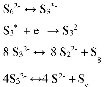
During charging of the battery, an electric potential is applied to the cathode and anode current collectors, with the stored reduced catholyte being pumped back over the cathode current collector again to be oxidized. During discharging the following reactions may be occurring:
4 S2 2- - 8 e-→ S8° ,
S8° + 4 S2-→4 S3 2-
S3 2- - e"→S 3 « S 62
3 6
4 S 2 + S ^→4 S 2
6 8 8
S8 2- -2e-→S
After charging and discharging, the catholyte again comprises the components described above. The redox active species may be:
S8 + 2e→S8 2- (1)
S3 *- + e→ S3 2- (2)
In which, reaction (1) is dominate reaction at higher voltage; reaction (2) is the dominate reaction at a lower voltage.
Certain metal-ligand coordination also possibly may be produced during charge/discharge process, such as (DMSO)n(LiTFSI)m(Li2S )i (m, n, 1 > 0).
Compared with aqueous redox flow cells, the volume energy density of the presently disclosed systems is much higher due to the increased voltage and capacity. For example, in certain embodiments, the non-aqueous redox flow batteries may have volume energy density values that are greater than 50 Wh/L, or greater than 100 Wh/L. In addition, sulfur is very cheap thus reducing the cost. Examples
Lithium trifluoromethanesulfonate (LiTf) comprised of Tf anion with high ionic association, was used as an additive to enhance the solubility of low order Li2Sxin DMSO solvent. Fig. 3 shows the effect of
LiTf addition on increasing solubility for insoluble L12S2 at different LiTf concentrations in DMSO solvent.
For salt/solvent mole ratio of 30 (DMS03o:LiTf), the solubility of L12S2 can be increased almost ten times higher than that in pure DMSO solvent. The solubility of other polysulfides with different chain lengths is also improved after the addition of LiTf (Fig. 4).
Concentrated salt electrolyte is employed to improve the capability of Li anode with DMSO-based electrolyte. When IM LiTf in DMSO is used in a Li-S battery, the charge-discharge curves show large fluctuations (Fig. 5a) due to the unstable interface between DMSO and lithium metal. When LiTf concentration is increased to more than IM, the curves in Fig. 5b became smoother. It was found that if LiTf was replaced by LiTFSI, similar increased solubility of short-chain polysulfides can be reached (Fig. 6). Again, IM LiTFSI in DMSO has abnormally long charge plateau due to the instability of Li metal in DMSO (Fig. 7a). Increasing LiTFSI concentration effectively prevents the parasitic reactions during charge (Fig. 7b). Significantly improved cycling stability (Fig. 8a) and Columbic efficiency (Fig. 8b) are observed in concentrated LiTFSI electrolytes with high reversible capacity at ca.1000-1200 mAh/g. These examples were performed with stationary button cells, with carbon sheet as cathode current collector, dissolved hi2Sx in DMSO-based solvent as catholyte, and Li counter and reference electrodes. In view of the many possible embodiments to which the principles of the disclosed systems, devices and compositions may be applied, it should be recognized that the illustrated embodiments are only preferred examples of the invention and should not be taken as limiting the scope of the invention.
Claims
1. A device comprising:
a lithium sulfur redox flow battery comprising an electrolyte composition comprising:
(i) a dissolved Li2Sx electroactive salt, wherein x >4;
(ii) a solvent selected from dimethyl sulfoxide, tetrahydrofuran, or a mixture thereof; and
(iii) a supporting salt at a concentration of at least 2 M, as measured by moles of supporting salt divided by the volume of the solvent without considering the volume change of the electrolyte after dissolving the supporting salt.
2. The device of claim 1, wherein the electroactive salt is L12S8.
3. The device of claim 1 or 2, wherein the solvent consists essentially of dimethyl sulfoxide.
4. The device of claim 1 or 2, wherein the solvent consists of dimethyl sulfoxide.
5. The device of any one of claims 1 to 4, wherein the supporting salt is selected from lithium trifluoromethanesulfonate, lithium bis(trifluoromethanesulphonyl) imide, L1CF2CO2, L1NO3, or a mixture thereof.
6. The device of claim 5, wherein the supporting salt is selected from lithium
trifluoromethanesulfonates or lithium bis(trifluoromethanesulphonyl) imide.
7. The device of any one of claims 1 to 6, further comprising a lithium metal anode.
8. The device of any one of claims 1 to 7, wherein the electrolyte composition is a catholyte.
9. The device of any one of claims 1 to 8, further comprising:
a first half cell part comprising a current collector and the electrolyte composition, wherein the electrolyte composition is a catholyte; and
a second half cell part comprising a lithium metal anode.
10. The device of claim 9, wherein the current collector comprises carbon felt.
11. The device of any one of claims 1 to 10, wherein the supporting salt is lithium
bis(trifluoromethanesulphonyl) imide at a concentration of 2M to 4M.
12. The device of claim 11, wherein the solvent consists essentially of dimethyl sulfoxide.
13. An energy storage system comprising:
a lithium sulfur redox flow battery comprising an electrolyte composition comprising:
(i) a dissolved Li2Sx electroactive salt, wherein x >4;
(ii) a solvent selected from dimethyl sulfoxide, tetrahydrofuran, or a mixture thereof; and
(iii) a supporting salt at a concentration of at least 2 M, as measured by moles of supporting salt divided by the volume of the solvent without considering the volume change of the electrolyte after dissolving the supporting salt; and
a source of the electrolyte composition fluidly coupled to the lithium sulfur redox flow battery.
14. The system of claim 13, wherein the lithium sulfur redox flow battery comprises:
a first half cell part comprising a current collector and the electrolyte composition, wherein the electrolyte composition is a catholyte; and
a second half cell part comprising a lithium metal anode;
wherein the source of the electrolyte composition is fluidly coupled to the first half cell part.
Applications Claiming Priority (2)
| Application Number | Priority Date | Filing Date | Title |
|---|---|---|---|
| US14/530,442 | 2014-10-31 | ||
| US14/530,442 US9954229B2 (en) | 2014-10-31 | 2014-10-31 | Electrolyte for stable cycling of high-energy lithium sulfur redox flow batteries |
Publications (2)
| Publication Number | Publication Date |
|---|---|
| WO2016069934A1 true WO2016069934A1 (en) | 2016-05-06 |
| WO2016069934A9 WO2016069934A9 (en) | 2016-09-29 |
Family
ID=55853658
Family Applications (1)
| Application Number | Title | Priority Date | Filing Date |
|---|---|---|---|
| PCT/US2015/058131 Ceased WO2016069934A1 (en) | 2014-10-31 | 2015-10-29 | Electrolyte for stable cycling of high-energy lithium sulfur redox flow batteries |
Country Status (2)
| Country | Link |
|---|---|
| US (1) | US9954229B2 (en) |
| WO (1) | WO2016069934A1 (en) |
Families Citing this family (5)
| Publication number | Priority date | Publication date | Assignee | Title |
|---|---|---|---|---|
| US11177498B1 (en) | 2018-10-15 | 2021-11-16 | Ampcera Inc. | Redox flow batteries, components for redox flow batteries and methods for manufacture thereof |
| US12154702B1 (en) | 2018-10-15 | 2024-11-26 | Ampcera Inc. | Methods for manufacturing a freestanding solid state ionic conductive membrane |
| US11819806B1 (en) | 2018-10-15 | 2023-11-21 | Ampcera Inc. | Methods for manufacturing a solid state ionic conductive membrane on a macro porous support scaffold |
| US11600853B1 (en) | 2019-05-14 | 2023-03-07 | Ampcera Inc. | Systems and methods for storing, transporting, and handling of solid-state electrolytes |
| CN116845311B (en) * | 2023-08-03 | 2024-10-18 | 广州百盛电源科技有限公司 | Total sulfur flow battery and preparation method thereof |
Citations (3)
| Publication number | Priority date | Publication date | Assignee | Title |
|---|---|---|---|---|
| US20120135278A1 (en) * | 2009-06-09 | 2012-05-31 | Tomohisa Yoshie | Redox flow battery |
| US20130224538A1 (en) * | 2012-02-28 | 2013-08-29 | Uchicago Argonne Llc | Organic non-aqueous cation-based redox flow batteries |
| US20140302370A1 (en) * | 2013-02-04 | 2014-10-09 | Massachusetts Institute Of Technology | Metal sulfide electrodes and energy storage devices thereof |
Family Cites Families (15)
| Publication number | Priority date | Publication date | Assignee | Title |
|---|---|---|---|---|
| US4071665A (en) | 1972-09-18 | 1978-01-31 | E. I. Du Pont De Nemours And Company | High energy density battery with dioxolane based electrolyte |
| CA2072488C (en) | 1991-08-13 | 2002-10-01 | Andrew Webber | Nonaqueous electrolytes |
| KR100326467B1 (en) * | 2000-07-25 | 2002-02-28 | 김순택 | A Electrolyte for Lithium Sulfur batteries |
| WO2008013409A1 (en) | 2006-07-28 | 2008-01-31 | Lg Chem, Ltd. | Secondary batteries comprising eutectic mixture and preparation method thereof |
| US9786944B2 (en) * | 2008-06-12 | 2017-10-10 | Massachusetts Institute Of Technology | High energy density redox flow device |
| KR20130111591A (en) | 2010-12-06 | 2013-10-10 | 미쓰이 가가쿠 가부시키가이샤 | Melt-blown nonwoven fabric, and production method and device for same |
| WO2012097164A1 (en) * | 2011-01-13 | 2012-07-19 | Enervault Corporation | Porous electrode with improved conductivity |
| US8828574B2 (en) * | 2011-11-15 | 2014-09-09 | Polyplus Battery Company | Electrolyte compositions for aqueous electrolyte lithium sulfur batteries |
| US8889300B2 (en) * | 2012-02-27 | 2014-11-18 | California Institute Of Technology | Lithium-based high energy density flow batteries |
| US9190696B2 (en) * | 2013-05-16 | 2015-11-17 | Nanotek Instruments, Inc. | Lithium secondary batteries containing lithium salt-ionic liquid solvent electrolyte |
| KR102067764B1 (en) * | 2013-05-29 | 2020-01-20 | 삼성전자주식회사 | Positive electrode for Lithium battery and lithium metal battery using the same |
| US9368831B2 (en) * | 2013-06-10 | 2016-06-14 | Nanotek Instruments, Inc. | Lithium secondary batteries containing non-flammable quasi-solid electrolyte |
| US9601805B2 (en) * | 2013-07-22 | 2017-03-21 | Nanotek Instruments, Inc. | Process for producing non-flammable quasi-solid electrolyte and electrolyte-separator for lithium battery applications |
| US9276293B2 (en) | 2013-08-30 | 2016-03-01 | Southwestern Research Institute | Dynamic formation protocol for lithium-ion battery |
| KR102149334B1 (en) | 2013-10-21 | 2020-08-28 | 삼성전자주식회사 | cathode active material and cathode and sodium secondary battery using the same |
-
2014
- 2014-10-31 US US14/530,442 patent/US9954229B2/en active Active
-
2015
- 2015-10-29 WO PCT/US2015/058131 patent/WO2016069934A1/en not_active Ceased
Patent Citations (3)
| Publication number | Priority date | Publication date | Assignee | Title |
|---|---|---|---|---|
| US20120135278A1 (en) * | 2009-06-09 | 2012-05-31 | Tomohisa Yoshie | Redox flow battery |
| US20130224538A1 (en) * | 2012-02-28 | 2013-08-29 | Uchicago Argonne Llc | Organic non-aqueous cation-based redox flow batteries |
| US20140302370A1 (en) * | 2013-02-04 | 2014-10-09 | Massachusetts Institute Of Technology | Metal sulfide electrodes and energy storage devices thereof |
Also Published As
| Publication number | Publication date |
|---|---|
| US20160126580A1 (en) | 2016-05-05 |
| WO2016069934A9 (en) | 2016-09-29 |
| US9954229B2 (en) | 2018-04-24 |
Similar Documents
| Publication | Publication Date | Title |
|---|---|---|
| Mauger et al. | Tribute to Michel Armand: from rocking chair–Li-ion to solid-state lithium batteries | |
| Kimura et al. | A highly-concentrated poly (ethylene carbonate)-based electrolyte for all-solid-state Li battery working at room temperature | |
| US8889300B2 (en) | Lithium-based high energy density flow batteries | |
| Wang et al. | A single-ion gel polymer electrolyte based on polymeric lithium tartaric acid borate and its superior battery performance | |
| CN105304976B (en) | Lithium-air battery with cathode separated from free lithium ions | |
| CN103843191B (en) | The electrolyte of lithium-air battery | |
| CN103370830B (en) | Nonaqueous electrolyte air cell | |
| CN108963193B (en) | Artificial SEI transplantation | |
| US10411286B2 (en) | Alkali/oxidant battery | |
| CN102771000A (en) | Nonaqueous electrolyte solution type secondary battery and nonaqueous electrolyte solution for nonaqueous electrolyte solution type secondary battery | |
| CN103415953A (en) | Lithium-air battery | |
| AU2017292179B2 (en) | Non-aqueous redox flow batteries | |
| US9954229B2 (en) | Electrolyte for stable cycling of high-energy lithium sulfur redox flow batteries | |
| WO2018002296A1 (en) | Method of forming a secondary battery | |
| CN102386356A (en) | Film former-free electrolyte/separator system and use thereof in electrochemical energy accumulators | |
| JP2015521344A (en) | Aluminum-air battery and storage battery system | |
| JP2016122650A (en) | All-solid metal-metal battery | |
| CN108933293B (en) | Phosphonium-based ionic liquids for lithium metal-based batteries | |
| Guo et al. | Inhibition of polysulfide shuttling in high-polarity electrolytes via liquid/quasi-solid interface in lithium-sulfur batteries | |
| WO2015187240A1 (en) | High-energy-density, nonaqueous, redox flow batteries having iodine-based species | |
| Zhang et al. | A high power density dual-electrolyte lithium-silver battery with Celgard® 2325 separator | |
| WO2015079689A1 (en) | High capacity alkali/oxidant battery | |
| Kim et al. | Improving the stability of an organic battery with an ionic liquid-based polymer electrolyte | |
| KR20160096071A (en) | Sodium-halogen secondary cell | |
| KR20190006375A (en) | Redox Flow Battery using Sodium-Biphenyl |
Legal Events
| Date | Code | Title | Description |
|---|---|---|---|
| 121 | Ep: the epo has been informed by wipo that ep was designated in this application |
Ref document number: 15855122 Country of ref document: EP Kind code of ref document: A1 |
|
| NENP | Non-entry into the national phase |
Ref country code: DE |
|
| 122 | Ep: pct application non-entry in european phase |
Ref document number: 15855122 Country of ref document: EP Kind code of ref document: A1 |