WO2016058261A1 - 一种基于网络的扁平路由的实现方法 - Google Patents
一种基于网络的扁平路由的实现方法 Download PDFInfo
- Publication number
- WO2016058261A1 WO2016058261A1 PCT/CN2014/093962 CN2014093962W WO2016058261A1 WO 2016058261 A1 WO2016058261 A1 WO 2016058261A1 CN 2014093962 W CN2014093962 W CN 2014093962W WO 2016058261 A1 WO2016058261 A1 WO 2016058261A1
- Authority
- WO
- WIPO (PCT)
- Prior art keywords
- network
- layer
- host
- switch
- packet
- Prior art date
- Legal status (The legal status is an assumption and is not a legal conclusion. Google has not performed a legal analysis and makes no representation as to the accuracy of the status listed.)
- Ceased
Links
Images


Classifications
-
- H—ELECTRICITY
- H04—ELECTRIC COMMUNICATION TECHNIQUE
- H04L—TRANSMISSION OF DIGITAL INFORMATION, e.g. TELEGRAPHIC COMMUNICATION
- H04L45/00—Routing or path finding of packets in data switching networks
- H04L45/66—Layer 2 routing, e.g. in Ethernet based MAN's
-
- H—ELECTRICITY
- H04—ELECTRIC COMMUNICATION TECHNIQUE
- H04L—TRANSMISSION OF DIGITAL INFORMATION, e.g. TELEGRAPHIC COMMUNICATION
- H04L45/00—Routing or path finding of packets in data switching networks
- H04L45/12—Shortest path evaluation
- H04L45/122—Shortest path evaluation by minimising distances, e.g. by selecting a route with minimum of number of hops
-
- H—ELECTRICITY
- H04—ELECTRIC COMMUNICATION TECHNIQUE
- H04L—TRANSMISSION OF DIGITAL INFORMATION, e.g. TELEGRAPHIC COMMUNICATION
- H04L45/00—Routing or path finding of packets in data switching networks
- H04L45/32—Flooding
-
- H—ELECTRICITY
- H04—ELECTRIC COMMUNICATION TECHNIQUE
- H04L—TRANSMISSION OF DIGITAL INFORMATION, e.g. TELEGRAPHIC COMMUNICATION
- H04L45/00—Routing or path finding of packets in data switching networks
- H04L45/74—Address processing for routing
- H04L45/745—Address table lookup; Address filtering
-
- H—ELECTRICITY
- H04—ELECTRIC COMMUNICATION TECHNIQUE
- H04L—TRANSMISSION OF DIGITAL INFORMATION, e.g. TELEGRAPHIC COMMUNICATION
- H04L47/00—Traffic control in data switching networks
- H04L47/10—Flow control; Congestion control
- H04L47/12—Avoiding congestion; Recovering from congestion
- H04L47/125—Avoiding congestion; Recovering from congestion by balancing the load, e.g. traffic engineering
Definitions
- the present invention relates to the field of the Internet, and in particular, to a method for implementing a flat route based on a network.
- the traditional Internet is a packet-switched network covering the whole world.
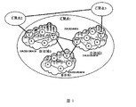
- IP routing technology is the core of the network (see Figure 1).
- each communication entity has a unique IP address and belongs to an autonomous domain (AS).
- AS autonomous domain
- One or more ASs constitute a POP, and multiple POPs are interconnected to form the Internet today.
- intra-domain routes are constructed in each AS domain through internal routing protocols such as RIP and OSPF.
- Each AS uses BGP to construct inter-domain routes, and finally realizes network-wide communication.
- IP routing technology is a hierarchical routing technology. Take the IPv4 network as an example.
- the address space is a 32-bit binary number.
- the address space is divided into three types of addresses, which correspond to prefixes of lengths of 8, 16, and 24, respectively.
- IPv4 also adds the work of classless inter-domain routing (CIDR), so that the prefix length can be set to 13-27 more flexibly.
- CIDR classless inter-domain routing
- Due to the hierarchical address space, the IP network can use the route aggregation technology to aggregate routing entries that reach the destination IP address of the same prefix, which greatly reduces the size of the routing table. This is also an effective extension of the IP network.
- the hierarchical structure of the IP network couples the host location with its identity, and also brings issues such as network mobility and network management.
- a flat route is a technology that directly routes according to the identity of a communication entity.
- an identity identifier is a flat label that is only used to mark the identity of a communication entity.
- the IP route corresponding to it is not related to its location, and is also called Hierarchical Routing (HR).
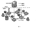
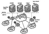
- SDN is a centralized network architecture that abstracts the network into data planes and control planes, and clearly divides the two so that the behavior of the data plane depends only on the decision of the control plane (see Figure 2).
- the data plane and the control plane exist in the network node at the same time.
- Each network node implements data forwarding, and also needs to run a distributed routing algorithm to calculate routing information, thereby implementing control of the network state. Adjustment.
- the nodes in the SDN network are only responsible for high-performance forwarding of data, and all routing and other control decisions are handled by independent control planes.
- OpenFlow is the first and most popular implementation of SDN today.
- the data plane is composed of OpenFlow switches
- the control plane is composed of controllers, and the two establish connections through secure channels. This constitutes the entire network.
- each switch contains a flow table for packet matching, and its main working mode is flow matching and action. When a packet matches an entry in the flow table, the associated action is executed. When the match fails, the packet is sent to the control plane via the secure channel in the form of OpenFlow protocol packets, and is processed by a network controller such as NOx.
- NOx network controller
- the controller has a global topology of the entire network and is capable of configuring flow tables in OpenFlow switches in the network. Therefore, when the controller receives a packet from the data plane, any stream can be processed in any way defined by the "software".
- the flow table is the most important component of the OpenFlow switch, and its function has also increased with the evolution of the OpenFlow standard.
- the OpenFlow 1.0 standard is the most widely used standard that has been supported by many vendors.
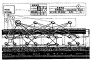
- the standard defines flows as twelve-tuples (see Figure 3) that contain the various important fields in the packet header from the physical layer (the port into which the packet enters the switch) to the transport layer (port number).
- the tuples in OpenFlow also support the function of wildcarding. When configuring the matching items of the flow table, some fields can be marked as ignored by masking. When the switch performs group matching, it will ignore these masks. The domain of the code. This wildcard entry is called the Wildcard Match Filed. Correspondingly, all the fields that are set are called Exact Match Filed.
- Centralized network control is a new research direction of flat routing, but most of these research solutions can only be applied to data center networks.
- Typical solutions include Portland, Identity and VL2.
- the solution proposed by Portland is similar to the present invention.
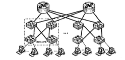
- the core idea of Portland is to use the fat tree network topology common in data center networks (see Figure 4) and address translation of the access layer switches to maintain the semantics of Layer 2 Ethernet throughout the data center network. To achieve flat routing.
- the switches belonging to a Layer 2 switching node POD are connected to a network centralized controller called Fabric Manager (FM).
- FM Fabric Manager
- hosts in different PODs communicate, they send out The packet will be first transmitted to the FM, and then the FM will perform the corresponding address translation according to the start and end address of the communication and the location of the POD of the current communication host, and finally route to the destination address.
- the basis of the address conversion is mainly It is a network topology of data center fat trees.
- the present invention provides a method for implementing a network-based flat route, which solves the problem of the prior art's dependence on a specific topology of the data center, so that the scheme does not have the universality problem.
- the present invention provides a method for implementing a network-based flat route, which includes the following steps: (A) dividing a network into a data plane and a control plane, and establishing a route matching wildcards across Layer 2 networks; (B) Control plane Establish an exact matching rule for each cross-layer communication flow; (C) Control plane maintains the location information of all hosts.
- the step (A) includes: a topology discovery method of the global network of the control plane maintenance network, including the following: (A1) When a new switch is connected to the controller, the controller immediately configures a Flow table rule, the rule matches a specific link discovery protocol LLDP packet whose source MAC address is set to the identity of the switch, and the action is flooding to other ports; (A2) the controller periodically sends a link discovery protocol LLDP is grouped into each switch connected to the controller, wherein the source MAC address of each LLDP is set to the DPID of the switch to which it is sent; (A3) the link discovery protocol LLDP packet received by each switch matches In the matching rule installed in the first step, the packet will be flooded to all other ports; (A4) if the flooded packet enters the connected Layer 2 network, it will be ignored and discarded.
- A1 When a new switch is connected to the controller, the controller immediately configures a Flow table rule, the rule matches a specific link discovery protocol LLDP packet whose source MAC address
- the controller can pass The source MAC address of the packet learns the source switch of the packet, and according to the DPID of the switch that uploads the packet, information about one side of the network topology can be obtained; (A6) the control plane collects information on all sides of the network to obtain The topology of the entire network.
- establishing a cross-Layer 2 network communication path is a full-source shortest path between switch network nodes connected to the Layer 2 network, which is specifically: using the Floyd-Warshal algorithm,
- the shortest path between all nodes can be calculated at the cost of O(V ⁇ 3) time complexity; after calculating the full source shortest path, the control plane needs to configure the wildcard matching rule according to the calculation result, and the matching rule is to the destination switch.
- the DPID is matched as the destination MAC address and forwarded along the shortest path. Multipath forwarding and redundant links are set up so that the traffic between the Layer 2 networks can be load balanced. If the link is found to be faulty, the link is implemented in time. Fast link switching.
- the control faces the host location tracking, and the location tracking includes two modes: active host tracking and passive host tracking; the working mode of the passive host tracking does not require software or network to the host side.
- the protocol stack is modified, and the matching failure packet sent to the controller generated by the host attempting to establish communication is completed; the active host tracking is completed by the process, and the process monitors the running status of the network card, and immediately sends a message when the network card is connected.
- the fixed group is sent to the control plane, and the control plane obtains the location information of the host.
- the step (C) further includes an IP address mapping, where the control plane generates an ARP response, and the MAC address of the response is connected to the Layer 2 network where the host that initiates the ARP request is located.
- the MAC address of the switch port to which the switch is sent if the destination IP address is converted to the corresponding MAC address according to the working mode of the Ethernet, after the host receives the response, the MAC address is forwarded as the destination MAC address, because the host In this Layer 2 network, the switch in the network does not contain routing entries to the host, so the packet is flooded in the network until all packets are dropped by the network; if the IP address is converted into an exchange
- the port MAC address provides a basis for the packet to be routed in the Layer 2 network, so that the packet can eventually be routed to the switching network and routed to the destination address.
- the method further includes the following steps: (D1) Host1 first sends an ARP request in the Layer 2 network to which it belongs, for parsing the MAC address of Host2; (D2) The ARP request will be broadcast in the Layer 2 network and will eventually be forwarded to the ports of the two switches. If the ARP request fails to match in the switch, the request will be forwarded to the controller; (D3) The controller receives the ARP request. After that, a first switch is selected as the first hop switch for communication across the Layer 2 communication path, and an ARP reply message is sent to the Layer 2 network, and the response maps the IP address of Host2 to the port eth1 of the first switch.
- Host1 After receiving the response, Host1 will initiate a connection establishment request, and will send a TCP SYN packet with OFMAC1.1 as the destination MAC address; (D5) the TCP SYN packet will be forwarded to The first switch, but also because it does not match the flow table, is sent to the controller; (D6) after receiving the TCP SYN packet, the controller searches the global host location table according to the destination IP address to obtain the destination host Host2.
- the information of the second switch connected to the Layer 2 network is installed with the exact matching rule in the first and last switches of the communication.
- the packet is sent back to the first switch; (D7) TCP The SYN will first match the exact match rule set in the previous step in OFS1, which will set the destination MAC address of the packet to OFMAC4 and forward it to the next hop; (D8) the packet header of the modified header Routing is performed according to the communication path between the Layer 2 networks established in advance, and finally routed to the second switch, at which time it will match the exact matching rule installed in the switch, and the rule will modify both the source and destination MACs. Address, modify it to OFMAC4.1 and HMAC2 respectively, and then the packet will be sent to the target Layer 2 network; (D9) The packet sent to the destination Layer 2 network will be delivered to the final destination host according to the Ethernet exchange. Host2; (D10) After receiving the connection establishment request, Host2 will send a TCP ACK message. At this time, a process symmetric with TCP SYN will occur until the information is routed to Host1. .
- the location information of the host includes the IP address of the host, the MAC address, and the identifier of the Layer 2 network where the host is located; the storage of the location information table of the host is pre-screened by the bloomfilter, and then passed through the hash table. The way the lookup is organized, where the IP address is used as the value of the key, the MAC address, and the identity of the Layer 2 network.
- step (C) the control plane maintains the location information of all the hosts
- the location information is only the identity of the Layer 2 network where the host resides, not the exact location within the Layer 2 network where the host resides.
- the invention has the beneficial effects that the solution can be applied to any network topology, and does not need to be directly connected to the Layer 2 switch of the Layer 2 network where each host is located, which greatly reduces the number of network devices that need to be connected to the control plane.
- the host location tracking method used in the solution does not need to track the exact location of the Layer 2 network where the host is located, but only the identifier of the Layer 2 network where the host is located. Therefore, the size of the network is only related to the processing capability of the control plane. Due to the parallelism of the scheme, a distributed control architecture can also be adopted, so that the network based on the scheme can be further scaled up.
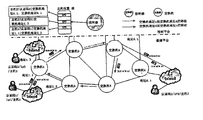
- FIG. 1 is a diagram of an IP-based network architecture of the present invention.
- FIG. 2 is a diagram showing the architecture of the SDN/OpenFlow network of the present invention.
- Figure 3 is a twelve-tuple map defined by the OpenFlow 1.0 protocol of the present invention.
- FIG. 4 is a schematic diagram of a data center network of the present invention.
- FIG. 5 is a schematic diagram of a centralized flat route applied to a data center by Portland in accordance with the present invention.
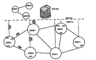
- FIG. 6 is a schematic diagram of a CFR network architecture of the present invention.
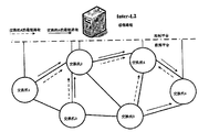
- FIG. 7 is a schematic diagram of topology discovery in a CFR network of the present invention.
- FIG. 8 is a schematic diagram of establishing a route between two layers of networks in a CFR network according to the present invention.
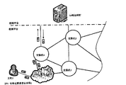
- FIG. 9 is a schematic diagram of host location tracking in a CFR network of the present invention.
- FIG. 10 is a schematic diagram of IP address mapping in a CFR network of the present invention.
- FIG. 11 is a schematic diagram of a cross-Layer 2 communication flow in a CFR network according to the present invention.
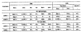
- FIG. 12 is a configuration diagram of a flow table involved in cross-layer communication in the CFR network of the present invention.
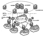
- FIG. 13 is a schematic diagram of a CFR network based on a distributed controller architecture of the present invention.
- CFR uses the idea of a network architecture of SDN to divide the network into data planes and control planes (see Figure 6).
- the data plane of the CFR is composed of a network composed of OpenFlow switches and a plurality of Layer 2 Ethernet networks connected thereto.
- the control plane is connected to each OpenFlow switch in the network to implement topology discovery, host location tracking, ARP request response, and cross-layer network communication.
- the Layer 2 network connected by the OpenFlow network can adopt any Ethernet technology, and only needs to maintain the original Layer 2 semantics of the Ethernet.
- the host location mentioned in the CFR is not the exact location of the host in the network (the specific port of the specific switch to which it is connected), but only the identity of the Layer 2 network where the host is located.
- the OpenFlow switch in CFR replaces the IP router.
- the software of the host side in the CFR network does not need to be modified (or very modified to implement the active host). Track and improve the overall performance of the network).
- the IP address is also used as the identity of the host, and the MAC address is used for routing.
- CFR does not limit the network topology and can be applied. In any network topology.
- the semantics of Ethernet itself can establish the connection between the two parties.
- the global host location map and the controller are required. Can be achieved.
- the control plane needs to maintain a global network view of the OpenFlow network.
- Ethernet the establishment of the network topology view can be implemented by switching the link layer discovery protocol LLDP between switches.
- CFR Since the controller is connected to every OpenFlow switch in the network, the LLDP protocol packet can be sent directly by the control plane without being sent by each OFS independently to the adjacent switch, which is the data defined by the SDN. The correct way to separate the face from the control surface.
- the specific topology discovery methods are as follows:
- the controller When a new OFS is connected to the controller, the controller immediately configures a flow table rule that matches a specific LLDP packet whose source MAC address is set to the OFS identifier (the identifier of the OFS is called DPID). To flood to other ports.
- the controller periodically transmits LLDP packets to each OFS connected to the controller, where the source MAC address of each LLDP is set to the DPID of the OFS to which it is sent.
- the flooded packet enters the Layer 2 network connected to OpenFlow, it is ignored and discarded. If it enters other OFS ports, it will be forwarded to the controller because the flow table fails to match.
- the controller After receiving the LLDP packet that is uploaded because the matching fails, the controller can learn the source OFS of the packet by using the source MAC address of the packet, and then obtain one of the network topologies according to the DPID of the OFS that uploads the packet. Side information.
- control plane collects information on all sides of the network, it gets the topology of the entire network.
- the control sends a corresponding LLDP packet to OFS1-OFS6, wherein the LLDP sent to OFS1 is flooded to OFS2 and OFS3, and is sent to the control plane because the matching fails, and the control plane is then controlled.
- Information about the edges (OFS1-OFS2) and (OFS1-OFS3) in the network topology is obtained.
- the topology discovery will be performed periodically.
- the control plane can detect network changes in at most one cycle.
- the work of one topology discovery only needs to send V and receive 2E LLDP packets, and the overall generated control information is of the order of O(V+E).
- the control plane needs to complete the establishment of the communication path across the Layer 2 network. Since the Layer 2 network may be connected to any OFS, the path to be established here is actually the OpenFlow connected to the Layer 2 network. The full source shortest path between network nodes.
- the shortest path between all nodes can be calculated at the cost of O(V ⁇ 3) time complexity.
- various status information of network nodes may also be obtained, which may include port status of the node, link utilization, etc., which may assist the control plane to use such as link minimum cost or The criteria such as maximum utilization calculate the most "short" path.
- the control plane After the all-source shortest path is calculated, the control plane needs to configure the wildcard matching rules according to the calculation result. These matching rules match the DPID of the destination OFS as the destination MAC address and forward along the shortest path. Taking Figure 8 as an example, the dotted arrow describes the shortest path from any node in the network to OFS4. For the OFS1 node, the control plane only needs to configure a rule to match any packet with the destination MAC address of OFS4 and forward it to OFS2 is OK, and other nodes perform the same configuration. Since each node needs to maintain routing information to the shortest path of all other nodes, each configuration of the full source shortest path needs to generate V(V-1) configuration information, and each node needs to be saved (V- 1) Rules for matching wildcards.
- CFR aggregates traffic destined for the same Layer 2 network, which greatly reduces the need for wildcard matching flow table entries.
- OpenFlow networks that support OpenFlow 1.1 and higher standards, you can also set up multipath forwarding and redundant links, so that traffic between Layer 2 networks can be load balanced. When a link fault is found in the path, it can also be implemented. Fast link switching.
- Host location tracking is the core function to achieve location and identity separation.
- the control plane only needs to know the identity of the Layer 2 network where the host is located, and does not need to track the exact location of the host in the L2 network. Routing across Layer 2 areas. The control plane needs to update the location information of the host only when the host moves across the Layer 2 area.
- Location tracking can be implemented in both passive and active ways. Passive host tracking works in a way that does not require modification of the software or network protocol stack on the host side. It relies primarily on packets that fail to be sent to the controller and that are sent to the controller when the host attempts to establish communication. As shown in Figure 9, it is assumed that Host1 is a host that is newly added to the network. The host is connected to the Layer 2 network E1. The control plane does not know the location information of Host1. When hosts on other Layer 2 networks try to communicate with Host1. The control plane has no way to establish a related connection.
- the control plane can obtain the IP address and MAC address of Host1 through the matching failure packet sent by Host1 only when Host1 attempts to establish communication with the host in the Layer 2 network other than E1. Then, according to the connection between the Layer 2 network and the OpenFlow network maintained by the control plane, the identification information of the Layer 2 network where the host is located is obtained.
- the connection table of the Layer 2 network to the OpenFlow network is a static table, and is generally registered when the Layer 2 network joins the OpenFlow network, and is maintained by the network operator.
- Active host tracking enables the CFR network to more effectively grasp the location information of the host, and the implementation of this function only requires a simple background process to be installed on the host side.
- the process monitors the running status of the network card.
- the network card When the network card is connected, it immediately sends a fixed packet to the control plane, and the control plane can obtain the location information of the host.
- the active location report packet can be It is sent in a connectionless form (based on the UDP protocol) and can increase the period of active reporting or only when the host moves across Layer 2 or joins the network.
- the location information of a host includes the IP address of the host, the MAC address, and the identifier of the Layer 2 network where the host is located. Take the IPv4 network as an example. Assume that the identity of each Layer 2 network is also stored in four bytes. It takes only 14 bytes to store the location information of each host.
- the storage of the location information table of the host can be pre-screened by the bloomfilter, and then organized by means of a hash table search, wherein the IP address is used as a key, a MAC address, and an identifier of the layer 2 network as a value.
- database technology can also be adopted, so that the host location database can be used by multiple controllers at the same time.
- CFR The core idea of CFR is to maintain the second layer semantics of the whole network.
- the IP address is used as the identity of the host, and the MAC address is used as the actual route identifier. Similar to Ethernet, CFR also needs an ARP-like protocol to map IP addresses to MAC addresses. Related mechanisms.
- the work of IP address mapping in CFR is also implemented by ARP protocol.
- ARP response is not generated by the destination host, but is generated by the control plane, and the MAC address of the response is not.
- the MAC address of the destination IP address is the MAC address of the OpenFlow switch port to which the host that is the ARP request is connected. The main reason is to avoid spreading the MAC addresses of all hosts in the global Layer 2 network. . If the CFR is converted to the corresponding MAC address according to the working mode of the Ethernet, after the host receives the response, the MAC address is forwarded as the destination MAC address, because the host is not in the Layer 2 network.
- the switch in the network does not contain a routing entry to the host, and the packet is flooded in the network until all packets are dropped by the network. If the IP address is translated into the OpenFlow port MAC address, it provides a basis for the packet to be routed in the Layer 2 network, so that the packet can be finally routed to the OpenFlow network and through the cross-Layer 2 communication described in the next section. The method is routed to the destination address.
- the CFR address mapping mechanism also ensures isolation between each Layer 2 network, avoiding each Layer 2 network.
- the switch needs to learn the routes of all hosts on the entire network.
- Cross-Layer 2 communication is the most common form of communication in the CFR network architecture and relies on the full functionality of the control plane discussed above. Assume that the control plane has obtained the OpenFlow network topology view and established the full source shortest path, and maintains the host location information of the entire network. After the host knows the destination IP address (which can be obtained by default or DNS service), As shown in Figure 11, the flow of the entire communication between Host 1 and Host 2 is described as follows:
- Host1 first sends an ARP request in the Layer 2 network to which it belongs to resolve the MAC address of Host2.
- the ARP request will be broadcast in the Layer 2 network and will eventually be forwarded to the ports of OFS1 and OFS3. Since these ARP requests fail to match in the switch, the request will be forwarded to the controller.
- the controller After receiving the ARP request, the controller selects an OpenFlow switch (OFS1) as the first-hop switch for communication across the Layer 2 communication path, and sends an ARP reply message to the Layer 2 network.
- OFS1 OpenFlow switch
- the response maps the IP address of Host2.
- the MAC address of the port eth1 of OFS1 is OFMAC1.1.
- Host1 After receiving the response, Host1 initiates a connection setup request and will send a TCP SYN packet with OFMAC1.1 as the destination MAC address.
- the TCP SYN packet will be forwarded to OFS1, but is also sent to the controller because there is no matching flow table.
- the controller After receiving the TCP SYN packet, the controller searches the global host location table according to the destination IP address, and obtains the information (port MAC address) of the OpenFlow switch to which the Layer 2 network where the destination host Host2 is connected, and at the same time in the communication. Precise matching rules are installed in the first two openFlow switches (OFS1 and OFS4). Once the rules are set, the packet is sent back to OFS1.
- the TCP SYN will first match the exact match rule set in the previous step in OFS1, which will set the destination MAC address of the packet to OFMAC4 and forward it to the next hop.
- the packet whose header is modified will be routed according to the communication path between the Layer 2 networks established in advance, and finally routed to OFS4, at which time it will match the exact matching rule installed in the switch, and the rule will be modified at the same time.
- the source and destination MAC addresses are modified to OFMAC4.1 and HMAC2, respectively.
- the packet is then sent to the target Layer 2 network.
- the packets sent to the destination Layer 2 network are delivered to the final destination host Host2 in the manner of Ethernet switching.
- Host2 After receiving the connection establishment request, Host2 will send a TCP ACK message. At this time, a process symmetric with TCP SYN will occur until the information is routed to Host1.
- the controller After the connection is established, the communication between Host1 and Host2 will only be fast forwarded through the data plane, and the support of the control plane is no longer needed. If the communication occurs between two Layer 2 networks connected to the same OpenFlow switch, the controller only needs to establish a rule for each party of the communication to modify the exact match between the source and destination MAC addresses. If the sending method has already cached the MAC address corresponding to the destination IP before the communication occurs (the corresponding address in the CFR is the port MAC address of the OpenFlow switch connected to the host), the host only needs to go through the process of Step 4 to Step 10.
- the present invention adopts a centralized control network to connect multiple Layer 2 networks.
- the architecture assumes that each Layer 2 network can be connected by any Layer 2 Ethernet technology. Only network devices connected to each Layer 2 network need to be connected.
- Control plane ; the host location in the network is maintained by the control plane, and the host location information is only the identity of the Layer 2 network where the host is located, not the exact location in the Layer 2 network where the host is located; the rules for matching with the Layer 2 network are matched.
- control plane is logically centralized.
- a distributed control plane approach may be adopted.
- the core idea is to pre-establish a wild-match matching route across the Layer 2 network, and then the control plane is for each An exact matching rule is established across the Layer 2 communication flow, and the location information of all hosts is maintained by the control plane.
Landscapes
- Engineering & Computer Science (AREA)
- Computer Networks & Wireless Communication (AREA)
- Signal Processing (AREA)
- Data Exchanges In Wide-Area Networks (AREA)
Abstract
本发明涉及互联网领域,其公开了基于网络的扁平路由的实现方法,包括以下步骤:(A)将网络划分为数据面与控制面,建立跨二层网络间的通配匹配的路由;(B)控制面为每一个跨二层通信流建立精确匹配规则;(C)控制面维护所有主机的位置信息。本发明的有益效果是:方案可以应用于任意的网络拓扑,且不需要直接连接到每一个主机所在二层网络的二层交换机,大大减少了所需要连接到控制面的网络设备的数量。
Description
本发明涉及互联网领域,尤其涉及一种基于网络的扁平路由的实现方法。
传统的互联网是一张覆盖全球的分组交换网络,IP路由技术是该网络的组网核心(见图1)。在IP网络的基本通信应用中,每一个通信实体拥有一个唯一的IP地址,并属于一个自治域(AS),一个或多个AS构成一个POP,多个POP再通过互联的方式构成如今的互联网。在该种网络架构下,每个AS域内通过诸如RIP,OSPF等内部路由协议构造域内路由,各个AS之间则通过BGP协议来构造域间的路由,最终实现全网的通信。
IP路由技术一种层次化的路由技术。以IPv4网络为例,其地址空间为32位二进制数,该地址空间被分成了三类地址,分别对应了8、16、24等长度的前缀。为了更有效的利用地址空间,IPv4还加入了无类域间路由(classless inter-domain routing,CIDR)的工作方式,使得前缀长度可以更灵活地被设置为13~27。由于采用了层次化的地址空间,IP网络可以采用路由聚合的技术,将到达同一个前缀目的IP地址的路由表项进行汇聚,大大减小了路由表的大小,而这也是IP网络能够有效扩展到全球的重要原因。IP网络层次化的地址结构将主机位置与其身份标识进行了耦合,也带来了诸如网络移动性,以及网络管理的问题。
扁平路由是一种直接按照通信实体的身份标识进行路由的技术,相较于IP网络中层次化划分的IP地址标识,身份标识是一种扁平的标签,仅用于标记通信实体的身份,而与其所在位置不相关联,与之相对应的IP路由也被称为层次化路由(Hierarchical Routing,HR)。
SDN是一种集中式的网络体系架构,其将网络抽象成数据面与控制面,并对两者进行清晰的划分,使得数据面的行为仅依赖于控制面的决策(见图2)。在传统的IP网络中,数据面与控制面同时存在于网络结点中,每个网络结点实现数据转发的同时,还需要运行分布式的路由算法计算路由信息,进而实现对网络状态的控制调节。而SDN网络中的结点只负责数据的高性能转发,一切路由以及其它的控制决策由独立的控制面负责。OpenFlow是最早也是如今最流行的SDN的实现方案。在OpenFlow网络中,数据面由OpenFlow交换机构成,控制面则由控制器构成,两者通过安全通道建立连接,
进而构成整个网络。在OpenFlow网络中,每一个交换机包含一个用于进行分组匹配的流表,其主要的工作方式为流匹配与动作。当分组匹配到流表中的表项时,相关联的动作便会执行。当匹配失败,该分组则会通过安全通道以OpenFlow协议数据包的方式被送至控制面,被诸如NOX的网络控制器进行处理。控制器拥有整个网络的全局拓扑,且能够对网络中的OpenFlow交换机中的流表进行配置。因此,当控制器从数据面接收到分组时,便可以按照任何“软件”定义的方式对任意流进行处理。流表是OpenFlow交换机中最重要的组成部件,其功能也随着OpenFlow标准的演进而增多。其中,OpenFlow 1.0标准是如今使用最广且已被诸多厂商支持的标准。该标准将流定义为十二元组(见图3),这些元组包含了分组包头中从物理层(分组进入交换机的端口)到传输层(端口号)的各个重要域。OpenFlow中的元组还支持通配的功能,即在配置流表的匹配项目时,可以通过掩码的方式将某些域标记成忽略,当交换机进行分组匹配的时候,其会忽略这些进行掩码的域。这种通配的表项被称为通配匹配表项(Wildcard Match Filed),与之对应的,所有域都进行了设定的表项称为精确匹配表项(Exact Match Filed)。
集中式网络控制是扁平路由的一个新的研究方向,但这类研究方案大多只能应用于数据中心网络,其中的典型方案有Portland,Identity以及VL2。其中Portland所提出的方案与本发明较为类似。
Portland(见图5)的核心思想是利用数据中心网络常见的胖树形网络拓扑(见图4),并通过接入层交换机的地址转换,从而实现整个数据中心网络保持二层以太网的语义,进而实现扁平路由。
在Portland所提出的方案中,同属于一个二层交换结点POD的交换机均连接到称为Fabric Manager(FM)的网络集中控制器中,当处于不同POD中的主机进行通信时,其发出的分组首先会传递到FM中,而后FM会根据该通信的起止地址,以及当前通信主机所在POD的位置进行对应的地址转换,从而最终路由到目的地址,值得指出的是,其地址转换的依据主要是数据中心胖树型的网络拓扑。
Portland等主要应用于数据中心的扁平路由的方案,虽然有效地解决了数据中心虚拟机迁移的问题,以及降低了网络管理的成本,但其对于数据中心特定拓扑的依赖使得该类方案并不具备普遍性,此外该类方案的网络架构假设一个网络控制器连接到全网的所有接入交换机,使得网络的规模的受限于接入交换所能接入主机的个数,以及控制器的处理能力。
【发明内容】
为了解决现有技术中的问题,本发明提供了一种基于网络的扁平路由的实现方法,解决现有技术中对于数据中心特定拓扑的依赖使得该类方案并不具备普遍性的问题。
本发明提供了一种基于网络的扁平路由的实现方法,包括以下步骤:(A)将网络划分为数据面与控制面,建立跨二层网络间的通配匹配的路由;(B)控制面为每一个跨二层通信流建立精确匹配规则;(C)控制面维护所有主机的位置信息。
作为本发明的进一步改进:所述步骤(A)之前包括:控制面维护网络的全局网络的拓扑发现方法,包括如下:(A1)当一个新的交换机连接到控制器时,控制器立刻配置一条流表规则,该规则匹配一源MAC地址被设定为交换机的标识的特定的链路发现协议LLDP分组,动作为泛洪到其它端口上;(A2)控制器周期性地发送链路发现协议LLDP分组到每一个连接到控制器的交换机中,其中每一个LLDP的源MAC地址均被设置为被发送到的交换机的DPID;(A3)每个交换机接收到的链路发现协议LLDP分组匹配了第一步中安装的匹配规则,该分组将泛洪到所有其它端口上;(A4)泛洪的分组若进入了连接到的二层网络时则被忽略与丢弃,若进入到其它交换机端口,则会因为流表匹配失败的原因被转发到控制器;(A5)控制器接收到因为匹配失败的原因被上传的链路发现协议LLDP分组后,可以通过该分组的源MAC地址得知该分组的源交换机,再根据上传该分组的交换机的DPID,便能够得到网络拓扑中的一条边的信息;(A6)控制面收集到网络所有边的信息以获得整个网络的拓扑。
作为本发明的进一步改进:所述步骤(A)中,建立跨二层网络通信路径为连接有二层网络的交换机网络结点间的全源最短路径,其具体为:利用Floyd-Warshal算法,所有结点之间的最短路径能够以O(V^3)的时间复杂度的代价完成计算;计算好全源最短路径后,控制面需要按照计算结果配置通配匹配规则,匹配规则以目的交换机的DPID作为目的MAC地址进行匹配,并沿着最短路径进行转发;设置多径转发以及冗余链路,使得二层网络之间的通信流量能够负载均衡,若路径中发现链路故障时及时实现快速的链路切换。
作为本发明的进一步改进:所述步骤(C)中,控制面对主机位置跟踪,位置跟踪包括主动主机跟踪和被动主机跟踪两种方式;被动主机跟踪的工作方式不需要对主机端的软件或网络协议栈进行修改,通过主机尝试建立通信时所产生的被送到控制器的匹配失败的分组;主动主机跟踪通过进程来完成,该进程将监控网卡的运行状态,在网卡连接时,立刻发送一个固定的分组到控制面中,控制面获取到主机的位置信息。
作为本发明的进一步改进:所述步骤(C)中还包括IP地址映射,其具体为:控制面产生产生ARP应答,应答的MAC地址是发起ARP请求的主机所在二层网络所连接
到的交换机端口的MAC地址;若按照以太网的工作方式,将目的IP转换为对应的MAC地址,在主机收到该应答后便会以该MAC地址作为目的MAC地址进行转发,由于该主机并不在此二层网路内,网络中的交换机不包含有到该主机的路由表项,于是会将该分组在网络内进行泛洪,直至所有的分组被网络丢弃;若将IP地址转化为交换的端口MAC地址,则为分组在二层网络中的路由提供了依据,使得分组最终能够被路由到交换网络,并路由到目的地址。
作为本发明的进一步改进:还包括跨二层通信的步骤,其具体如下:(D1)Host1先在其所属的二层网络内发送一个ARP请求,用于解析Host2的MAC地址;(D2)该ARP请求会在二层网络内广播,最终会被转发到两个交换机的端口上,若ARP请求在交换机中匹配失败,则该请求都会被递交至控制器;(D3)控制器收到ARP请求后,将会选择一个第一交换机作为通信跨二层通信路径的首跳交换机,并发送一个ARP应答的消息到二层网络中,该应答将Host2的IP地址映射为第一交换机的端口eth1的MAC地址OFMAC1.1;(D4)Host1接收到应答后,便会发起连接建立的请求,将会发送以OFMAC1.1作为目的MAC地址的TCP SYN分组;(D5)该TCP SYN分组会被转发至第一交换机,但同样因为没有匹配流表,被送至控制器;(D6)控制器收到TCP SYN的分组后,便会按照目的IP地址搜索全局的主机位置表,得到目的主机Host2所在二层网络所连接到的第二交换机的信息,同时在该通信的首尾两个交换机中安装精确匹配的规则,设置完规则后,便将分组重新送回至第一交换机;(D7)TCP SYN首先会匹配于OFS1中在前一步所设置的精确匹配的规则,该规则会将分组的目的MAC地址设置为OFMAC4,并将其转发至下一跳;(D8)被修改了包头的分组会按照提前建立的二层网络之间的通信路径进行路由,最终被路由到第二交换机,此时其会匹配于安装在该交换机中的精确匹配的规则,该规则将同时修改其源与目的MAC地址,将其分别修改为OFMAC4.1以及HMAC2,而后分组会被送至目标二层网络;(D9)被送到目的二层网络的分组会按照以太网交换的方式被递交到最终的目标主机Host2;(D10)Host2接收到连接建立的请求后,便会发送TCP ACK的消息,此时一个与TCP SYN对称的过程将会发生,直至该信息被路由到Host1处。
作为本发明的进一步改进:主机的位置信息包括该主机的IP地址,MAC地址,以及该主机所处的二层网络的标识;主机的位置信息表的存储采用bloomfilter预筛,再通过哈希表查找的方式组织,其中IP地址作为键,MAC地址以及二层网络的标识作为值。
作为本发明的进一步改进:步骤(C)中,控制面维护所有主机的位置信息中的
位置信息仅为主机所在二层网络的标识,而不是该主机所在二层网络内的确切的位置。
本发明的有益效果是:本方案可以应用于任意的网络拓扑,且不需要直接连接到每一个主机所在二层网络的二层交换机,大大减少了所需要连接到控制面的网络设备的数量。本方案中所采用的主机位置跟踪的方法,也并不需要跟踪主机所在二层网络的准确位置,而只是该主机所在二层网络的标识,因此网络的规模仅与控制面的处理能力有关。由于方案的具有并行性,还可以采用分布式的控制架构,使得基于该方案的网络能够进一步地扩大规模。
图1是本发明基于IP的网络体系架构图。
图2是本发明SDN/OpenFlow网络体系架构图。
图3是本发明OpenFlow 1.0协议所定义的十二元组图。
图4是本发明数据中心网络示意图。
图5是本发明Portland应用于数据中心的集中式扁平路由示意图。
图6是本发明CFR网络体系架构示意图。
图7是本发明CFR网络中的拓扑发现示示意图。
图8是本发明CFR网络中的二层网络间路由的建立示意图。
图9是本发明CFR网络中的主机位置跟踪示意图。
图10是本发明CFR网络中的IP地址映射示意图。
图11是本发明CFR网络中跨二层通信流程示意图。
图12是本发明CFR网络中跨二层通信涉及的流表的配置图。
图13是本发明基于分布式控制器架构的CFR网络示意图。
下面结合附图说明及具体实施方式对本发明进一步说明。
一些网络术语的定义:


在一实例中,CFR采用SDN的网络架构的思想,将网络划分为数据面与控制面(见图6)。其中,CFR的数据面由OpenFlow交换机所组成的网络以及与之相连接的多个二层以太网而构成。控制面则连接到网络中的每一台OpenFlow交换上,实现拓扑发现,主机位置跟踪,ARP请求应答以及跨二层网络通信的功能。需要注意的是,由OpenFlow网络所连接的二层网络可以采用任意的以太网技术,只需要保持以太网原本的二层语义即可。此外,在CFR中所提到的主机位置并不是主机在网络中的准确位置(所连接到的具体交换机的具体端口),而仅仅只是该主机所在的二层网络的标识。
相较传统网络拓扑,CFR中的OpenFlow交换机代替了IP路由器,为了实现CFR在IP网络中的部署与实验,CFR网络中主机端的软件不需要进行修改(或进行非常小的修改,以便实现主动主机跟踪,提高网络的整体性能)。在CFR网络中,IP地址同样作为主机的身份标识,而MAC地址则用于进行路由,与Portland等应用于数据中心的集中式扁平路由的方案不同的是,CFR不对网络拓扑进行限定,可应用于任意的网络拓扑。
当通信仅发生在同一个二层网络中,以太网自身的语义便可实现双方连接的建立,而对于跨二层网络之间的通信,则通需要过全局的主机位置图以及控制器的辅助才可实现。
全局网络拓扑的维护
控制面需要维护OpenFlow网络的全局网络视图。在以太网中,网络拓扑视图的建立一般可以通过交换机之间互相交换链路层发现协议LLDP的方式实现。在CFR中,
由于控制器连接到了网络中每一个OpenFlow交换机,LLDP协议分组可以由控制面直接发送,而不需要由每一个OFS独立地发送给与之相邻的交换机,而这也正是SDN所定义的数据面与控制面分离的正确做法。具体的拓扑发现方法如下:
当一个新的OFS连接到控制器时,控制器立刻配置一条流表规则,该规则匹配一源MAC地址被设定为OFS的标识(OFS的标识被称为DPID)的特定的LLDP分组,动作为泛洪到其它端口上。
控制器周期性地发送LLDP分组到每一个连接到控制器的OFS中,其中每一个LLDP的源MAC地址均被设置为被发送到的OFS的DPID。
由于每个OFS接收到的LLDP分组匹配了第一步中安装的匹配规则,该分组将泛洪到所有其它端口上。
泛洪的分组若进入了连接到OpenFlow上的二层网络时则被忽略与丢弃,若进入到其它OFS端口,则会因为流表匹配失败的原因被转发到控制器。
控制器接收到因为匹配失败的原因被上传的LLDP分组后,可以通过该分组的源MAC地址得知该分组的源OFS,再根据上传该分组的OFS的DPID,便能够得到网络拓扑中的一条边的信息。
当控制面收集到网络所有边的信息后,便得到了整个网络的拓扑。
以图7为例,控制面向OFS1-OFS6均发送了对应的LLDP的分组,其中发送到OFS1的LLDP被泛洪到OFS2以及OFS3,由于匹配失败,均被送到了控制面,此时控制面便得到了网络拓扑中边(OFS1-OFS2)和(OFS1-OFS3)的信息。
该拓扑发现将被周期性的执行,当网络拓扑发生变化时,控制面最多只需要一个周期的时间便能够检测到网络的变化。对于保护有V个结点以及E条边的网络拓扑,一次拓扑发现的工作只需要发送V个以及接收2E个LLDP分组,整体所产生的控制信息的量级为O(V+E)。
跨二层网络间通信路径的维护
完成了拓扑发现后,控制面接下来需要完成跨二层网络通信路径的建立,由于二层网络可能连接到任意的OFS上,实际上这里所需要建立的路径实际上是连接有二层网络的OpenFlow网络结点间的全源最短路径。
在已知网络拓扑的情况下,在V个结点的图中,通过运行Floyd-Warshal算法,所有结点之间的最短路径能够以O(V^3)的时间复杂度的代价完成计算。控制面除了可
以维护全局网络拓扑信息外,还可以获得网络结点的各种状态信息,这些状态信息可能包括结点的端口状态、链路利用率等,这些信息可以辅助控制面使用诸如链路最低成本或最高利用率等准则计算最“短”路径。
计算好全源最短路径后,控制面需要按照计算结果配置通配匹配规则,这些匹配规则以目的OFS的DPID作为目的MAC地址进行匹配,并沿着最短路径进行转发。以图8为例,虚线箭头描述的是网络中任意一个结点到OFS4的最短路径,对于OFS1结点,控制面只需要配置一条规则匹配目的MAC地址为OFS4的任意分组,并将其转发至OFS2即可,其它结点同样执行相同的配置。由于每个结点都需要维护到其它全部结点的最短路径的路由信息,每次执行全源最短路径的配置需要产生V(V-1)条配置信息,每个结点需要保存(V-1)条通配匹配的规则。
相较于传统的基于IP最长前缀匹配的路由聚合的方法,CFR将目标到同一个二层网络的流量聚合在一起,大大地减小了对通配匹配的流表表项的需求。对于支持OpenFlow 1.1以及更高版本标准的OpenFlow网络,还可以设置多径转发以及冗余链路,使得二层网络之间的通信流量能够负载均衡,当路径中发现链路故障时,也能够实现快速的链路切换。
主机位置跟踪
主机位置跟踪是实现位置与身份分离的核心功能,在CFR的网络架构中,控制面只需要知道主机所在的二层网络的标识,而不需要跟踪主机在L2网络中确切的位置,便能够实现跨二层区域的路由。仅当主机跨二层区域进行移动时,控制面才需要更新主机的位置信息。
位置跟踪可以有被动与主动两种方式实现。被动主机跟踪的工作方式不需要对主机端的软件或网络协议栈进行修改,主要依赖于主机尝试建立通信时所产生的被送到控制器的匹配失败的分组。如图9所示,假设Host1是新加入到网络中的主机,该主机连接到二层网络E1,此时控制面并不知道Host1的位置信息,当其它二层网络的主机尝试与Host1通信时,控制面没办法建立相关的连接。若Host1工作在被动跟踪的工作模式下,控制面只有当Host1尝试与E1以外的二层网络中的主机建立起通信时,才能够通过Host1所发出的匹配失败的分组得到Host1的IP以及MAC地址,再根据控制面所维护的各个二层网络与OpenFlow网络连接表,得到该主机所在二层网络的标识信息。其中,二层网络到OpenFlow网络的连接表是静态表,一般在二层网络加入到OpenFlow网络时进行登记,由网络运营商进行维护。
主动主机跟踪则使得CFR网络更有效地掌握主机的位置信息,而该功能的实现也只是需要在主机端安装一个简单的后台进程。该进程将监控网卡的运行状态,在网卡连接时,立刻发送一个固定的分组到控制面中,控制面便能够获取到主机的位置信息,为了降低控制面的处理开销,该主动位置报告分组可以采用无连接的形式发送(基于UDP协议),并可增大主动报告的周期或仅在主机跨二层移动或新加入网路时才进行位置报告。
对于每一个主机的位置,控制面只需要存储少量的信息。一个主机的位置信息包括该主机的IP地址,MAC地址,以及该主机所处的二层网络的标识。以IPv4网络为例,假设每个二层网络的标识也以四字节进行存储,保存每个主机的位置信息仅需要14个字节。
主机的位置信息表的存储则可以采用bloomfilter预筛,再通过哈希表查找的方式组织,其中IP地址作为键,MAC地址以及二层网络的标识作为值。在CFR大规模网络的实现中,还可以采用数据库技术,使得主机位置数据库能够同时被多个控制器查询使用。
IP地址映射
CFR的核心思想是维护全网的二层语义,IP地址作为主机的身份标识,而MAC地址作为实际的路由标识,与以太网类似,CFR也需要一个类似ARP协议将IP地址映射到MAC地址的相关机制。
在CFR中IP地址映射的工作同样采用ARP协议实现,但与以太网中的ARP协议不同的是,ARP应答并不是由目的主机产生,而是由控制面产生,且应答的MAC地址也并不是目的IP所对应的MAC地址,而是发起ARP请求的主机所在二层网络所连接到的OpenFlow交换机端口的MAC地址,主要原因是为了避免将全局所有主机的MAC地址散布到每一个二层网络中。若CFR中按照以太网的工作方式,将目的IP转换为对应的MAC地址,在主机收到该应答后便会以该MAC地址作为目的MAC地址进行转发,由于该主机并不在此二层网路内,网络中的交换机不包含有到该主机的路由表项,于是会将该分组在网络内进行泛洪,直至所有的分组被网络丢弃。而若将IP地址转化为OpenFlow的端口MAC地址,则为分组在二层网络中的路由提供了依据,使得分组最终能够被路由到OpenFlow网络,并通过下一节中所介绍的跨二层通信的方法路由到目的地址。
CFR的地址映射机制还确保了每个二层网络之间的隔离,避免每个二层网络中的
交换机需要学习到全网所有主机的路由。
跨二层通信流程
跨二层通信是CFR网络架构中最普遍的通信方式,其依赖于前面所讨论的控制面的全部功能。假设控制面已经获得了OpenFlow网络拓扑视图以及建立了全源最短路径,并且维护了全网的主机位置信息,在主机已知了目的IP地址(可通过预设或者DNS服务的方式获得),则如图11中所示,Host 1与Host 2的整个通信的流程描述如下:
Host1先在其所属的二层网络内发送一个ARP请求,用于解析Host2的MAC地址。
该ARP请求会在二层网络内广播,最终会被转发到OFS1以及OFS3的端口上,由于这些ARP请求在交换机中匹配失败,则该请求都会被递交至控制器。
控制器收到ARP请求后,将会选择一个OpenFlow交换机(OFS1)作为通信跨二层通信路径的首跳交换机,并发送一个ARP应答的消息到二层网络中,该应答将Host2的IP地址映射为OFS1的端口eth1的MAC地址OFMAC1.1。
Host1接收到应答后,便会发起连接建立的请求,将会发送以OFMAC1.1作为目的MAC地址的TCP SYN分组。
该TCP SYN分组会被转发至OFS1,但同样因为没有匹配流表,被送至控制器。
控制器收到TCP SYN的分组后,便会按照目的IP地址搜索全局的主机位置表,得到目的主机Host2所在二层网络所连接到的OpenFlow交换机的信息(端口MAC地址),同时在该通信的首尾两个OpenFlow交换机(OFS1与OFS4)中安装精确匹配的规则。设置完规则后,便将分组重新送回至OFS1。
TCP SYN首先会匹配于OFS1中在前一步所设置的精确匹配的规则,该规则会将分组的目的MAC地址设置为OFMAC4,并将其转发至下一跳。
被修改了包头的分组会按照提前建立的二层网络之间的通信路径进行路由,最终被路由到OFS4,此时其会匹配于安装在该交换机中的精确匹配的规则,该规则将同时修改其源与目的MAC地址,将其分别修改为OFMAC4.1以及HMAC2。而后分组会被送至目标二层网络。
被送到目的二层网络的分组会按照以太网交换的方式被递交到最终的目标主机Host2。
Host2接收到连接建立的请求后,便会发送TCP ACK的消息,此时一个与TCP SYN对称的过程将会发生,直至该信息被路由到Host1处。
在连接建立之后,Host1与Host2之间的通信将只经过数据面的快速转发,而不再需要控制面的辅助。若通信发生在连接到同一个OpenFlow交换机的两个二层网络之间,则控制器只需要为通信的每一方建立一条同时修改源与目的MAC地址的精确匹配的规则即可。如在通信发生之前发送方法已经缓存了目的IP所对应的MAC地址(在CFR中该对应地址是与主机所连接的OpenFlow交换机的端口MAC地址),则该主机只需经历Step4到Step10的过程。
本发明通过采用集中控制网络连接多个二层网络的体系结构,该体系架构假设各个二层网络可以采用任意的二层以太网技术进行组网,只有连接各个二层网络的网络设备需要连接到控制面;网络中的主机位置由控制面维护,而主机位置信息只是主机所在二层网络的标识,而不是该主机所在二层网络内的确切的位置;二层网络间采用通配匹配的规则预先建立好全源路由的方法;跨二层通信时,控制面建立确定数量的精确匹配的路由的方法。
实际上任何符合“匹配+动作”的集中控制语义的网络都能够实现本方案。在本方案模型中,控制面为逻辑集中,在实际部署中可能采用分布式控制面的方法,但核心思想还是预先建立跨二层网络间的通配匹配的路由,再由控制面为每一个跨二层通信流建立精确匹配规则,同时由控制面维护所有主机的位置信息。
以上内容是结合具体的优选实施方式对本发明所作的进一步详细说明,不能认定本发明的具体实施只局限于这些说明。对于本发明所属技术领域的普通技术人员来说,在不脱离本发明构思的前提下,还可以做出若干简单推演或替换,都应当视为属于本发明的保护范围。
Claims (8)
- 一种基于网络的扁平路由的实现方法,其特征在于:包括以下步骤:(A)将网络划分为数据面与控制面,建立跨二层网络间的通配匹配的路由;(B)控制面为每一个跨二层通信流建立精确匹配规则;(C)控制面维护所有主机的位置信息。
- 根据权利要求1所述的基于网络的扁平路由的实现方法,其特征在于:所述步骤(A)之前包括:控制面维护网络的全局网络的拓扑发现方法,包括如下:(A1)当一个新的交换机连接到控制器时,控制器立刻配置一条流表规则,该规则匹配一源MAC地址被设定为交换机的标识DPID的特定的链路发现协议LLDP分组,动作为泛洪到其它端口上;(A2)控制器周期性地发送链路发现协议LLDP分组到每一个连接到控制器的交换机中,其中每一个LLDP的源MAC地址均被设置为被发送到的交换机的DPID(A3)每个交换机接收到的链路发现协议LLDP分组匹配了第一步中安装的匹配规则,该分组将泛洪到所有其它端口上;(A4)泛洪的分组若进入了连接到的二层网络时则被忽略与丢弃,若进入到其它交换机端口,则会因为流表匹配失败的原因被转发到控制器;(A5)控制器接收到因为匹配失败的原因被上传的链路发现协议LLDP分组后,可以通过该分组的源MAC地址得知该分组的源交换机,再根据上传该分组的交换机的标识DPID,便能够得到网络拓扑中的一条边的信息;(A6)控制面收集到网络所有边的信息以获得整个网络的拓扑。
- 根据权利要求1所述的基于网络的扁平路由的实现方法,其特征在于:所述步骤(A)中,建立跨二层网络通信路径为连接有二层网络的交换机网络结点间的全源最短路径,其具体为:利用Floyd-Warshal算法,所有结点之间的最短路径能够以O(V^3)的时间复杂度的代价完成计算;计算好全源最短路径后,控制面需要按照计算结果配置通配匹配规则,匹配规则以目的交换机的DPID作为目的MAC地址进行匹配,并沿着最短路径进行转发;设置多径转发以及冗余链路,使得二层网络之间的通信流量能够负载均衡,若路径中发现链路故障,能及时实现快速的链路切换。
- 根据权利要求1所述的基于网络的扁平路由的实现方法,其特征在于:所述步骤(C)中,控制面对主机位置跟踪,位置跟踪包括主动主机跟踪和被动主机跟踪两种方式;被动主机跟踪的工作方式不需要对主机端的软件或网络协议栈进行修改,通过主机尝试建立通信时所产生的被送到控制器的匹配失败的分组来实现;主动主机跟踪通过进程来完成,该进程将监控网卡的运行状态,在网卡连接时,立刻发送一个固定的分组到控制面中,控制面获取到主机的位置信息。
- 根据权利要求1所述的基于网络的扁平路由的实现方法,其特征在于:所述步骤(C)中还包括IP地址映射,其具体为:控制面产生ARP应答,应答的MAC地址是发起ARP请求的主机所在二层网络连接到的交换机端口的MAC地址;若按照以太网的工作方式,将目的IP转换为对应的MAC地址,在主机收到该应答后便会以该MAC地址作为目的MAC地址进行转发,由于该主机并不在此二层网路内,网络中的交换机不包含有到该主机的路由表项,于是会将该分组在网络内进行泛洪,直至所有的分组被网络丢弃;若将IP地址转化为交换机的接入端口MAC地址,则为分组在二层网络中的路由提供了依据,使得分组最终能够被路由到交换网络,并路由到目的地址。
- 根据权利要求1所述的基于网络的扁平路由的实现方法,其特征在于:还包括跨二层通信的步骤,其具体如下:(D1)Host1先在其所属的二层网络内发送一个ARP请求,用于解析Host2的MAC地址;(D2)该ARP请求会在二层网络内广播,最终会被转发到某个交换机的端口上,若ARP请求在交换机中匹配失败,则该请求都会被递交至控制器;(D3)控制器收到ARP请求后,将会选择一个第一交换机作为跨二层通信路径的首跳交换机,并发送一个ARP应答的消息到二层网络中,该应答将Host2的IP地址映射为第一交换机的端口eth1的MAC地址OFMAC1.1;(D4)Host1接收到应答后,便会发起连接建立的请求,将会发送以OFMAC1.1作为目的MAC地址的TCP SYN分组;(D5)该TCP SYN分组会被转发至第一交换机,但同样因为没有匹配流表,被送至控制器;(D6)控制器收到TCP SYN的分组后,便会按照目的IP地址搜索全局的主机位置表,得到目的主机Host2所在二层网络所连接到的第二交换机的信息,同时在该通信的首尾两个交换机中安装精确匹配的规则,设置完规则后,便将分组重新送回至第一交换机;(D7)TCP SYN首先会匹配于第一交换机(OFS1)中在前一步所设置的精确匹配的规则,该规则会将分组的目的MAC地址修改为OFMAC4,并将其转发至下一跳;(D8)被修改了包头的分组会按照提前建立的二层网络之间的通信路径进行路由,最终被路由到第二交换机,此时其会匹配于安装在该交换机中的精确匹配的规则,该规则将同时修改其源与目的MAC地址,将其分别修改为OFMAC4.1以及HMAC2,而后分组会被送至目标二层网络;(D9)被送到目的二层网络的分组会按照以太网交换的方式被递交到最终的目标主机Host2;(D10)Host2接收到连接建立的请求后,便会发送TCP ACK的消息,此时一个与TCP SYN对称的过程将会发生,直至该信息被路由到Host1处。
- 根据权利要求1所述的基于网络的扁平路由的实现方法,其特征在于:主机的位 置信息包括该主机的IP地址,MAC地址,以及该主机所处的二层网络的标识;主机的位置信息表的存储采用bloomfilter预筛,再通过哈希表查找的方式组织,其中IP地址作为键,MAC地址以及二层网络的标识作为值。
- 根据权利要求1所述的基于网络的扁平路由的实现方法,其特征在于:步骤(C)中,控制面维护所有主机的位置信息中的位置信息仅为主机所在二层网络的标识,而不是该主机所在二层网络内的确切的位置。
Priority Applications (2)
| Application Number | Priority Date | Filing Date | Title |
|---|---|---|---|
| PCT/CN2014/093962 WO2016058261A1 (zh) | 2014-12-16 | 2014-12-16 | 一种基于网络的扁平路由的实现方法 |
| CN201480037522.7A CN105745882A (zh) | 2014-12-16 | 2014-12-16 | 一种基于网络的扁平路由的实现方法 |
Applications Claiming Priority (1)
| Application Number | Priority Date | Filing Date | Title |
|---|---|---|---|
| PCT/CN2014/093962 WO2016058261A1 (zh) | 2014-12-16 | 2014-12-16 | 一种基于网络的扁平路由的实现方法 |
Publications (1)
| Publication Number | Publication Date |
|---|---|
| WO2016058261A1 true WO2016058261A1 (zh) | 2016-04-21 |
Family
ID=55746017
Family Applications (1)
| Application Number | Title | Priority Date | Filing Date |
|---|---|---|---|
| PCT/CN2014/093962 Ceased WO2016058261A1 (zh) | 2014-12-16 | 2014-12-16 | 一种基于网络的扁平路由的实现方法 |
Country Status (2)
| Country | Link |
|---|---|
| CN (1) | CN105745882A (zh) |
| WO (1) | WO2016058261A1 (zh) |
Cited By (6)
| Publication number | Priority date | Publication date | Assignee | Title |
|---|---|---|---|---|
| CN112954064A (zh) * | 2021-02-24 | 2021-06-11 | 紫光云技术有限公司 | 一种云网络下实现高可用的组网方法 |
| CN113472572A (zh) * | 2021-06-28 | 2021-10-01 | 通号城市轨道交通技术有限公司 | 基于轨道交通信号系统的网络恢复方法及装置 |
| CN115150324A (zh) * | 2022-06-09 | 2022-10-04 | 南京邮电大学 | 一种基于可编程数据平面实现可变重路由阈值的方法及系统 |
| CN115955456A (zh) * | 2022-12-23 | 2023-04-11 | 明阳产业技术研究院(沈阳)有限公司 | 基于IPv6的企业园区网及组网方法 |
| CN116346630A (zh) * | 2023-04-10 | 2023-06-27 | 北京航天拓扑高科技有限责任公司 | 一种复杂网络拓扑信息解析方法 |
| CN116389359A (zh) * | 2023-03-20 | 2023-07-04 | 中国人民解放军军事科学院系统工程研究院 | 一种基于路由隔离的数据通信寻址方法和系统 |
Families Citing this family (3)
| Publication number | Priority date | Publication date | Assignee | Title |
|---|---|---|---|---|
| CN107018074B (zh) * | 2017-04-06 | 2019-11-05 | 湘潭大学 | 一种基于扁平化的网络连通路径快速搜索方法 |
| WO2019205082A1 (zh) * | 2018-04-27 | 2019-10-31 | 华为技术有限公司 | 一种网络及网络管理方法 |
| CN113630481B (zh) * | 2021-08-13 | 2023-11-28 | 上海微波技术研究所(中国电子科技集团公司第五十研究所) | Sdn中一种自动带内控制面构建方法及系统 |
Citations (5)
| Publication number | Priority date | Publication date | Assignee | Title |
|---|---|---|---|---|
| CN102045692A (zh) * | 2009-10-26 | 2011-05-04 | 中兴通讯股份有限公司 | 一种基于控制面与媒体面分离的网络架构实现的通信网络 |
| CN102158885A (zh) * | 2011-04-19 | 2011-08-17 | 北京交通大学 | 一体化网络接入子网路由协议移动性支持方法 |
| CN102291320A (zh) * | 2011-09-29 | 2011-12-21 | 杭州华三通信技术有限公司 | Mac地址学习方法和边缘设备 |
| CN103259732A (zh) * | 2013-04-03 | 2013-08-21 | 北京邮电大学 | 一种基于arp事件触发代理的sdn广播处理方法 |
| US20140269702A1 (en) * | 2013-03-14 | 2014-09-18 | Cisco Technology, Inc. | Interoperability of data plane based overlays and control plane based overlays in a network environment |
Family Cites Families (4)
| Publication number | Priority date | Publication date | Assignee | Title |
|---|---|---|---|---|
| CN102938794B (zh) * | 2012-11-14 | 2016-01-13 | 华为技术有限公司 | 地址解析协议arp消息转发方法、交换机和控制器 |
| US9729425B2 (en) * | 2012-11-29 | 2017-08-08 | Futurewei Technologies, Inc. | Transformation and unified control of hybrid networks composed of OpenFlow switches and other programmable switches |
| CN103905317B (zh) * | 2012-12-28 | 2017-05-03 | 中兴通讯股份有限公司 | 一种软件定义网络的报文处理方法和系统 |
| US9525597B2 (en) * | 2013-06-06 | 2016-12-20 | Dell Products, L.P. | System and method for base topology selection |
-
2014
- 2014-12-16 WO PCT/CN2014/093962 patent/WO2016058261A1/zh not_active Ceased
- 2014-12-16 CN CN201480037522.7A patent/CN105745882A/zh active Pending
Patent Citations (5)
| Publication number | Priority date | Publication date | Assignee | Title |
|---|---|---|---|---|
| CN102045692A (zh) * | 2009-10-26 | 2011-05-04 | 中兴通讯股份有限公司 | 一种基于控制面与媒体面分离的网络架构实现的通信网络 |
| CN102158885A (zh) * | 2011-04-19 | 2011-08-17 | 北京交通大学 | 一体化网络接入子网路由协议移动性支持方法 |
| CN102291320A (zh) * | 2011-09-29 | 2011-12-21 | 杭州华三通信技术有限公司 | Mac地址学习方法和边缘设备 |
| US20140269702A1 (en) * | 2013-03-14 | 2014-09-18 | Cisco Technology, Inc. | Interoperability of data plane based overlays and control plane based overlays in a network environment |
| CN103259732A (zh) * | 2013-04-03 | 2013-08-21 | 北京邮电大学 | 一种基于arp事件触发代理的sdn广播处理方法 |
Cited By (10)
| Publication number | Priority date | Publication date | Assignee | Title |
|---|---|---|---|---|
| CN112954064A (zh) * | 2021-02-24 | 2021-06-11 | 紫光云技术有限公司 | 一种云网络下实现高可用的组网方法 |
| CN113472572A (zh) * | 2021-06-28 | 2021-10-01 | 通号城市轨道交通技术有限公司 | 基于轨道交通信号系统的网络恢复方法及装置 |
| CN113472572B (zh) * | 2021-06-28 | 2024-01-05 | 通号城市轨道交通技术有限公司 | 基于轨道交通信号系统的网络恢复方法及装置 |
| CN115150324A (zh) * | 2022-06-09 | 2022-10-04 | 南京邮电大学 | 一种基于可编程数据平面实现可变重路由阈值的方法及系统 |
| CN115150324B (zh) * | 2022-06-09 | 2024-05-10 | 南京邮电大学 | 一种基于可编程数据平面实现可变重路由阈值的方法及系统 |
| CN115955456A (zh) * | 2022-12-23 | 2023-04-11 | 明阳产业技术研究院(沈阳)有限公司 | 基于IPv6的企业园区网及组网方法 |
| CN116389359A (zh) * | 2023-03-20 | 2023-07-04 | 中国人民解放军军事科学院系统工程研究院 | 一种基于路由隔离的数据通信寻址方法和系统 |
| CN116389359B (zh) * | 2023-03-20 | 2024-05-24 | 中国人民解放军军事科学院系统工程研究院 | 一种基于路由隔离的数据通信寻址方法和系统 |
| CN116346630A (zh) * | 2023-04-10 | 2023-06-27 | 北京航天拓扑高科技有限责任公司 | 一种复杂网络拓扑信息解析方法 |
| CN116346630B (zh) * | 2023-04-10 | 2026-04-24 | 北京航天拓扑高科技有限责任公司 | 一种复杂网络拓扑信息解析方法 |
Also Published As
| Publication number | Publication date |
|---|---|
| CN105745882A (zh) | 2016-07-06 |
Similar Documents
| Publication | Publication Date | Title |
|---|---|---|
| US11895026B2 (en) | Service function chaining SFC-based packet forwarding method, apparatus, and system | |
| WO2016058261A1 (zh) | 一种基于网络的扁平路由的实现方法 | |
| US10050877B2 (en) | Packet forwarding method and apparatus | |
| EP2974133B1 (en) | Method and system for controlling an underlying physical network by a software defined network | |
| US20210409308A1 (en) | Layer-2 network extension over layer-3 network using encapsulation | |
| US9391887B2 (en) | Mapping server, network system, packet forwarding method and program | |
| CN104104614B (zh) | 命名数据网络中的软件定义网络控制器系统及其方法 | |
| CN102638389B (zh) | 一种trill网络的冗余备份方法及系统 | |
| CN103905315B (zh) | 传送网络中所用的路由信息的虚拟化和分发的方法、设备和系统 | |
| US20150334057A1 (en) | Packet forwarding | |
| CN110061915B (zh) | 跨多个架构交换机的虚拟链路聚合的方法和系统 | |
| CN105391635B (zh) | 一种基于sdn的网络虚拟化方法 | |
| CN104243270A (zh) | 一种建立隧道的方法和装置 | |
| CN104580165B (zh) | 智慧协同网络中的一种协作缓存方法 | |
| CN101263696A (zh) | 对来自多宿主主机的数据分组进行路由 | |
| CN105721321A (zh) | 一种等价多路径的出接口更新方法及装置 | |
| US11356368B2 (en) | Pinning bi-directional network traffic to a service device | |
| CN105075196A (zh) | 控制器、通信系统、路径切换方法和程序 | |
| CN106656793A (zh) | 一种sdn网络与ip网络的数据交互方法 | |
| JPWO2014104277A1 (ja) | 制御装置、通信システム、通信ノードの制御方法及びプログラム | |
| CN108337168A (zh) | 流簇交换路由机制OpenFlow组表选择方法 | |
| Dumba et al. | A virtual ID routing protocol for future dynamics networks and its implementation using the SDN paradigm | |
| US12375401B2 (en) | Overlay route optimization across data centers | |
| WO2017107033A1 (zh) | 一种基于身份的集中控制式网络体系架构iccn | |
| Jain et al. | VEIL: A" Plug-&-Play" Virtual (Ethernet) Id Layer for Below IP Networking |
Legal Events
| Date | Code | Title | Description |
|---|---|---|---|
| 121 | Ep: the epo has been informed by wipo that ep was designated in this application |
Ref document number: 14903922 Country of ref document: EP Kind code of ref document: A1 |
|
| NENP | Non-entry into the national phase |
Ref country code: DE |
|
| 122 | Ep: pct application non-entry in european phase |
Ref document number: 14903922 Country of ref document: EP Kind code of ref document: A1 |