WO2016047159A1 - Bearing and bearing pad - Google Patents
Bearing and bearing pad Download PDFInfo
- Publication number
- WO2016047159A1 WO2016047159A1 PCT/JP2015/053805 JP2015053805W WO2016047159A1 WO 2016047159 A1 WO2016047159 A1 WO 2016047159A1 JP 2015053805 W JP2015053805 W JP 2015053805W WO 2016047159 A1 WO2016047159 A1 WO 2016047159A1
- Authority
- WO
- WIPO (PCT)
- Prior art keywords
- pad
- bearing
- opening
- rotating shaft
- sliding surface
- Prior art date
Links
Images


Classifications
-
- F—MECHANICAL ENGINEERING; LIGHTING; HEATING; WEAPONS; BLASTING
- F16—ENGINEERING ELEMENTS AND UNITS; GENERAL MEASURES FOR PRODUCING AND MAINTAINING EFFECTIVE FUNCTIONING OF MACHINES OR INSTALLATIONS; THERMAL INSULATION IN GENERAL
- F16C—SHAFTS; FLEXIBLE SHAFTS; ELEMENTS OR CRANKSHAFT MECHANISMS; ROTARY BODIES OTHER THAN GEARING ELEMENTS; BEARINGS
- F16C33/00—Parts of bearings; Special methods for making bearings or parts thereof
- F16C33/02—Parts of sliding-contact bearings
- F16C33/04—Brasses; Bushes; Linings
- F16C33/06—Sliding surface mainly made of metal
- F16C33/10—Construction relative to lubrication
-
- F—MECHANICAL ENGINEERING; LIGHTING; HEATING; WEAPONS; BLASTING
- F16—ENGINEERING ELEMENTS AND UNITS; GENERAL MEASURES FOR PRODUCING AND MAINTAINING EFFECTIVE FUNCTIONING OF MACHINES OR INSTALLATIONS; THERMAL INSULATION IN GENERAL
- F16C—SHAFTS; FLEXIBLE SHAFTS; ELEMENTS OR CRANKSHAFT MECHANISMS; ROTARY BODIES OTHER THAN GEARING ELEMENTS; BEARINGS
- F16C33/00—Parts of bearings; Special methods for making bearings or parts thereof
- F16C33/02—Parts of sliding-contact bearings
- F16C33/04—Brasses; Bushes; Linings
- F16C33/06—Sliding surface mainly made of metal
- F16C33/10—Construction relative to lubrication
- F16C33/1025—Construction relative to lubrication with liquid, e.g. oil, as lubricant
- F16C33/106—Details of distribution or circulation inside the bearings, e.g. details of the bearing surfaces to affect flow or pressure of the liquid
- F16C33/108—Details of distribution or circulation inside the bearings, e.g. details of the bearing surfaces to affect flow or pressure of the liquid with a plurality of elements forming the bearing surfaces, e.g. bearing pads
-
- F—MECHANICAL ENGINEERING; LIGHTING; HEATING; WEAPONS; BLASTING
- F01—MACHINES OR ENGINES IN GENERAL; ENGINE PLANTS IN GENERAL; STEAM ENGINES
- F01D—NON-POSITIVE DISPLACEMENT MACHINES OR ENGINES, e.g. STEAM TURBINES
- F01D25/00—Component parts, details, or accessories, not provided for in, or of interest apart from, other groups
- F01D25/16—Arrangement of bearings; Supporting or mounting bearings in casings
-
- F—MECHANICAL ENGINEERING; LIGHTING; HEATING; WEAPONS; BLASTING
- F16—ENGINEERING ELEMENTS AND UNITS; GENERAL MEASURES FOR PRODUCING AND MAINTAINING EFFECTIVE FUNCTIONING OF MACHINES OR INSTALLATIONS; THERMAL INSULATION IN GENERAL
- F16C—SHAFTS; FLEXIBLE SHAFTS; ELEMENTS OR CRANKSHAFT MECHANISMS; ROTARY BODIES OTHER THAN GEARING ELEMENTS; BEARINGS
- F16C17/00—Sliding-contact bearings for exclusively rotary movement
- F16C17/02—Sliding-contact bearings for exclusively rotary movement for radial load only
- F16C17/03—Sliding-contact bearings for exclusively rotary movement for radial load only with tiltably-supported segments, e.g. Michell bearings
-
- F—MECHANICAL ENGINEERING; LIGHTING; HEATING; WEAPONS; BLASTING
- F16—ENGINEERING ELEMENTS AND UNITS; GENERAL MEASURES FOR PRODUCING AND MAINTAINING EFFECTIVE FUNCTIONING OF MACHINES OR INSTALLATIONS; THERMAL INSULATION IN GENERAL
- F16C—SHAFTS; FLEXIBLE SHAFTS; ELEMENTS OR CRANKSHAFT MECHANISMS; ROTARY BODIES OTHER THAN GEARING ELEMENTS; BEARINGS
- F16C17/00—Sliding-contact bearings for exclusively rotary movement
- F16C17/04—Sliding-contact bearings for exclusively rotary movement for axial load only
- F16C17/06—Sliding-contact bearings for exclusively rotary movement for axial load only with tiltably-supported segments, e.g. Michell bearings
-
- F—MECHANICAL ENGINEERING; LIGHTING; HEATING; WEAPONS; BLASTING
- F16—ENGINEERING ELEMENTS AND UNITS; GENERAL MEASURES FOR PRODUCING AND MAINTAINING EFFECTIVE FUNCTIONING OF MACHINES OR INSTALLATIONS; THERMAL INSULATION IN GENERAL
- F16C—SHAFTS; FLEXIBLE SHAFTS; ELEMENTS OR CRANKSHAFT MECHANISMS; ROTARY BODIES OTHER THAN GEARING ELEMENTS; BEARINGS
- F16C17/00—Sliding-contact bearings for exclusively rotary movement
- F16C17/10—Sliding-contact bearings for exclusively rotary movement for both radial and axial load
-
- F—MECHANICAL ENGINEERING; LIGHTING; HEATING; WEAPONS; BLASTING
- F16—ENGINEERING ELEMENTS AND UNITS; GENERAL MEASURES FOR PRODUCING AND MAINTAINING EFFECTIVE FUNCTIONING OF MACHINES OR INSTALLATIONS; THERMAL INSULATION IN GENERAL
- F16C—SHAFTS; FLEXIBLE SHAFTS; ELEMENTS OR CRANKSHAFT MECHANISMS; ROTARY BODIES OTHER THAN GEARING ELEMENTS; BEARINGS
- F16C33/00—Parts of bearings; Special methods for making bearings or parts thereof
- F16C33/02—Parts of sliding-contact bearings
- F16C33/04—Brasses; Bushes; Linings
- F16C33/06—Sliding surface mainly made of metal
- F16C33/10—Construction relative to lubrication
- F16C33/1025—Construction relative to lubrication with liquid, e.g. oil, as lubricant
- F16C33/106—Details of distribution or circulation inside the bearings, e.g. details of the bearing surfaces to affect flow or pressure of the liquid
- F16C33/1065—Grooves on a bearing surface for distributing or collecting the liquid
-
- F—MECHANICAL ENGINEERING; LIGHTING; HEATING; WEAPONS; BLASTING
- F16—ENGINEERING ELEMENTS AND UNITS; GENERAL MEASURES FOR PRODUCING AND MAINTAINING EFFECTIVE FUNCTIONING OF MACHINES OR INSTALLATIONS; THERMAL INSULATION IN GENERAL
- F16C—SHAFTS; FLEXIBLE SHAFTS; ELEMENTS OR CRANKSHAFT MECHANISMS; ROTARY BODIES OTHER THAN GEARING ELEMENTS; BEARINGS
- F16C33/00—Parts of bearings; Special methods for making bearings or parts thereof
- F16C33/02—Parts of sliding-contact bearings
- F16C33/04—Brasses; Bushes; Linings
- F16C33/06—Sliding surface mainly made of metal
- F16C33/10—Construction relative to lubrication
- F16C33/1025—Construction relative to lubrication with liquid, e.g. oil, as lubricant
- F16C33/106—Details of distribution or circulation inside the bearings, e.g. details of the bearing surfaces to affect flow or pressure of the liquid
- F16C33/1085—Channels or passages to recirculate the liquid in the bearing
-
- F—MECHANICAL ENGINEERING; LIGHTING; HEATING; WEAPONS; BLASTING
- F16—ENGINEERING ELEMENTS AND UNITS; GENERAL MEASURES FOR PRODUCING AND MAINTAINING EFFECTIVE FUNCTIONING OF MACHINES OR INSTALLATIONS; THERMAL INSULATION IN GENERAL
- F16C—SHAFTS; FLEXIBLE SHAFTS; ELEMENTS OR CRANKSHAFT MECHANISMS; ROTARY BODIES OTHER THAN GEARING ELEMENTS; BEARINGS
- F16C37/00—Cooling of bearings
- F16C37/002—Cooling of bearings of fluid bearings
-
- F—MECHANICAL ENGINEERING; LIGHTING; HEATING; WEAPONS; BLASTING
- F16—ENGINEERING ELEMENTS AND UNITS; GENERAL MEASURES FOR PRODUCING AND MAINTAINING EFFECTIVE FUNCTIONING OF MACHINES OR INSTALLATIONS; THERMAL INSULATION IN GENERAL
- F16C—SHAFTS; FLEXIBLE SHAFTS; ELEMENTS OR CRANKSHAFT MECHANISMS; ROTARY BODIES OTHER THAN GEARING ELEMENTS; BEARINGS
- F16C2360/00—Engines or pumps
- F16C2360/23—Gas turbine engines
Definitions
- the present invention relates to a bearing that rotatably supports a rotating shaft via a bearing pad and to which lubricating oil is supplied between the bearing pad and the rotating shaft, and the bearing pad.
- ⁇ Tilting pad bearings and thrust pad bearings which comprise a bearing surface with a plurality of independent bearing pads, have the property of quickly absorbing the vibration of the rotating shaft.
- This type of bearing is widely applied to rotary machines such as steam turbines and gas turbines, paying attention to this characteristic.
- demands for higher output and lower loss are increasing more than ever. For this reason, it is necessary to reduce the bearing loss by reducing the size of the bearing that supports the rotating shaft of the rotating machine.
- the size of the bearing is reduced, bearing loss can be suppressed.
- the pressure receiving area of the bearing is reduced, the bearing load (weight received by the bearing per unit area) is increased and the temperature of the bearing pad is increased.
- the temperature of the bearing pad is higher on the inner peripheral side near the rotating shaft, for example, in the case of a journal bearing, It becomes higher toward the downstream side in the shaft rotation direction. That is, a temperature difference is generated inside the bearing pad, and therefore, the pad is deformed due to a difference in elongation (thermal expansion difference).
- a temperature difference is generated inside the bearing pad, and therefore, the pad is deformed due to a difference in elongation (thermal expansion difference).
- a tilting pad journal bearing when the temperature rises on the inner peripheral side near the rotating shaft inside the tilting pad (bearing pad) and a temperature difference occurs between the inner peripheral side and the outer peripheral side, the tilting pad causess deformation that increases the radius of curvature facing the rotation axis. For this reason, the load capacity of the bearing is reduced.
- the inner peripheral surface (support surface) of the tilting pad is opposed to the outer peripheral surface (supported surface) of the rotating shaft, and a lubricating oil film is formed in the gap between these opposing surfaces. Smoothly supports the rotating shaft.
- the temperature of the entire tilting pad is increased, the tilting pad is further greatly deformed, and finally the rotating shaft and the bearing come into contact (the rotating shaft cannot be loaded). For this reason, the load capacity of a bearing will fall. Furthermore, if the tilting pad is deformed, the dynamic stability of the tilting pad is also affected. That is, the damping coefficient is lowered, and the vibration of the rotating shaft cannot be absorbed quickly.
- the present invention has been made in view of the above-described problems, and an object thereof is to provide a bearing and a bearing pad that can suppress deformation of the bearing pad without increasing cost.
- the bearing of the present invention rotatably supports the rotating shaft via the bearing pad, and lubricating oil is provided between the bearing pad and the supported surface of the rotating shaft.
- a through-flow path reaching the second opening is provided.
- the bearing pad is provided so as to be tiltable with respect to a rotation direction of the rotary shaft, and the high temperature region is located at a pad rear portion of the sliding surface in a downstream region in the rotation direction of the rotary shaft, It is preferable that the second opening is located in the pad front portion in the upstream region in the rotational direction than the first opening.
- the high temperature region is preferably a region in a range of 70% to 100% of the length of the sliding surface from the upstream edge of the sliding surface in the rotation direction.
- the second opening is disposed on a back surface opposite to the sliding surface.
- the second opening is disposed on a front surface facing the upstream side in the rotation direction.
- the supported surface is a radial circumferential surface of the rotating shaft.
- the rotating shaft has a thrust collar projecting outward in the radial direction, and the supported surface is an axial end surface of the thrust collar.
- the bearing pad of the present invention is a bearing pad that rotatably supports a rotating shaft and is supplied with lubricating oil between a supported surface of the rotating shaft.
- a through passage extending from the first opening provided in the high temperature region of the sliding surface facing the supported surface toward the side away from the supported surface and reaching the second opening is provided. It is characterized by that.
- the lubricating oil flows through the through flow path from the first opening toward the second opening due to the differential pressure generated between the first opening and the second opening. That is, as the rotating shaft rotates, the lubricating oil receives a shearing force due to sliding while being pressurized between the supported surface of the rotating shaft and the sliding surface of the bearing pad facing the supported surface. Fever. For this reason, the lubricating oil in the vicinity of the sliding surface of the bearing pad close to the supported surface becomes high temperature and pressure. In particular, since the vicinity of the region where the lubricating oil is at a high pressure between the sliding surface and the supported surface is a high temperature region of the sliding surface, lubrication is performed in the first opening provided in the high temperature region of the sliding surface.
- the oil is at high temperature and pressure.
- the lubricating oil has a lower temperature and lower pressure than the first opening, and the gap is between the first opening and the second opening. Differential pressure is generated. Therefore, the lubricating oil flows through the through flow path from the first opening toward the second opening due to the differential pressure.
- the temperature of the bearing pad can be made uniform while suppressing the local high temperature and reducing the maximum temperature. Since the lubricating oil is made to flow through the through-flow path using the differential pressure, the temperature of the bearing pad is made uniform, so there is no need for a pump for circulating the lubricating oil through the through-flow path and for cooling separately from the lubricating oil. Therefore, it is not necessary to use a material having a high thermal conductivity for the material of the bearing pad. Therefore, deformation of the bearing pad can be suppressed without increasing the cost.
- the bearing pad has a wide range.
- the pad temperature can be made uniform. That is, the bearing pad is inclined such that the clearance between the rotation axis of the bearing pad and the rotation axis is wide at the front part of the pad in the upstream region of the rotation axis and narrow at the rear part of the pad in the downstream direction of rotation with the high temperature region. Therefore, the pressure of the lubricating oil between the rotating shaft and the bearing pad becomes higher as it goes downstream in the rotational direction, and the temperature of the lubricating oil becomes higher as it goes downstream in the rotational direction.
- disposing the second opening at the pad front part in the upstream region in the rotational direction from the first opening is to provide the outlet (second opening) of the through flow path at a lower temperature portion of the bearing pad. Therefore, the temperature of the bearing pad can be made uniform over a wide range.
- the second opening When the second opening is disposed on the back surface on the opposite side to the sliding surface, the high-temperature lubricating oil that has exited the second opening, which is the outlet of the through passage, is re-applied to the sliding surface on the opposite side. Since the inflow is suppressed, the high temperature of the bearing pad can be suppressed.
- the through flow path is formed over a wide range of the bearing pad, so that the range in which the temperature is made uniform is widened. be able to.
- FIG. 1 is a schematic view showing a tilting pad journal bearing according to a first embodiment of the present invention, and is a cross-sectional view (transverse cross-sectional view) cut perpendicularly to the axis of a rotating shaft.
- FIG. 2A and FIG. 2B are schematic diagrams for explaining the operation and effect of the tilting pad journal bearing according to the first embodiment of the present invention, and FIG. 2A is the temperature distribution and oil film pressure of the tilting pad.
- FIG. 2B is a perspective view that also shows the temperature distribution of the tilting pad.
- FIG. FIG. 3A and FIG. 3B are schematic diagrams for explaining the operation and effect of the tilting pad journal bearing according to the second embodiment of the present invention, and FIG.
- FIG. 3A is the temperature distribution and oil film pressure of the tilting pad.
- FIG. 3B is a perspective view that also shows the temperature distribution of the tilting pad.
- FIG. 4A and 4B are schematic views showing the entire configuration of a tilting pad thrust bearing according to a third embodiment of the present invention.
- FIG. 4A is a partially cutaway side view
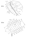
- FIG. FIG. 5A and 5B are schematic views showing a configuration of a tilting pad thrust bearing according to a third embodiment of the present invention.
- FIG. 5A is a cross-sectional view taken along the line CC of FIG. 4B
- FIG. 5B is a perspective view of the tilting pad.
- FIG. 6A and 6B are schematic views of a tilting pad thrust bearing according to a fourth embodiment of the present invention.
- FIG. 6A is a view corresponding to the CC cross section of FIG. 4B
- FIG. 6B is a perspective view of the tilting pad.
- a bearing 100 as a first embodiment of the present invention is a journal bearing that rotatably supports a rotating shaft 1 rotating in a direction indicated by an arrow (hereinafter also referred to as a rotating direction) A from a radial direction.
- the bearing 100 includes a plurality (two in this case) of tilting pads (bearing pads as the first embodiment of the present invention) 2 that support the rotating shaft 1 from vertically below, the rotating shaft 1 and the tilting pad 2.
- a plurality (two in this case) of pivots 5 are attached to the inner peripheral surface of the bearing housing 4.
- the tilting pads 2 are swingably supported by these pivots 5 respectively.
- the oil supply nozzles 6 are respectively provided in front of each tilting pad 2 (that is, upstream in the rotational direction A of the rotary shaft 1) and rearward (that is, downstream in the rotational direction A of the rotary shaft 1).
- An oil film is formed between the two sliding surfaces (hereinafter also referred to as pad sliding surfaces) 2a.
- each tilting pad 2 from the 1st opening (henceforth opening or entrance) 3a formed in the sliding face 2a, back 2b (sliding face)
- a through-flow path 3 is provided which reaches a second opening (hereinafter also referred to as an opening or an outlet) 3d formed on a surface opposite to 2a and facing the bearing housing 4).
- the through flow channel 3 has a bent structure including a flow channel 3b on the sliding surface 2a side and a flow channel 3c on the back surface 2b side, which has a different angle from the flow channel 3b. Yes.
- the lubricating oil in the vicinity of the pad sliding surface 2a close to the rotary shaft circumferential surface 1a is at high temperature and high pressure, and in particular, a region (hereinafter also referred to as a high temperature region) 2H located in the pad rear portion 2c of the sliding surface 2a ( In FIG. 2A and FIG. 2B, the lubricating oil has the highest temperature and pressure as described later, and the pressure of the lubricating oil around the region 2H is, for example, about 20 [Mpa] (200 atm) depending on the bearing specifications.
- the first opening 3a of the through channel 3 is disposed in the high temperature region 2H, which is also the high pressure region, while the second opening 3d of the through channel 3 is disposed in the pad back surface 2b.
- Lubricating oil around the second opening 3d on the pad back surface 2b is lubricating oil around the first opening 3a (lubricating oil under pressure and heat generation between the rotating shaft circumferential surface 1a and the pad sliding surface 2a). )
- the pressure is close to atmospheric pressure. For this reason, a large differential pressure is generated between the hydraulic pressure in the vicinity of the first opening 3a of the sliding surface 2a and the hydraulic pressure in the vicinity of the second opening 3d formed in the back surface 2b. Due to this differential pressure, the lubricating oil naturally circulates in the direction indicated by the arrow a with the first opening 3a as the inlet and the second opening 3d as the outlet. That is, the through passage 3 functions as an oil extraction hole.
- the through channel 3 will be further described with reference to FIGS. 2A and 2B.
- the plurality of lines on the tilting pad 2 are connected to the points where the temperatures ta to tk attached to the respective lines are assumed, assuming that the through passage 3 is not provided.
- It is an isotherm in FIG. 2B, only the isotherm for the temperature ta on the sliding surface 2a and the isotherm for the temperatures ti and tj on the back surface 2b are shown).
- the temperature ta to the temperature tk are higher in this order. In other words, the temperature ta is the highest among the temperature ta to the temperature tk, and the temperature tk is the lowest.
- a high temperature region here, a region surrounded by an isothermal line of the temperature ta
- 2H which is a region where the temperature is equal to or higher than ta.
- the reason why the high temperature region 2H is located at the pad rear portion 2c of the sliding surface 2a is as follows.
- the hydraulic pressure (hereinafter also referred to as oil film pressure) of the lubricating oil (lubricating oil film) in a pressurized state between the rotating shaft circumferential surface 1a and the tilting pad 2 is significantly higher than the hydraulic pressure on the pad back surface 2b side as described above.
- the oil film pressure increases particularly at the pad rear portion 2c. That is, the tilting pad 2 is inclined as shown in FIG.
- 2A (that is, the pad rear portion 2c in the downstream area in the rotation direction A is close to the rotating shaft circumferential surface 1a and the pad front in the upstream area in the rotation direction A
- the portion 2d is balanced in a posture separated from the rotary shaft circumferential surface 1a.
- 2A indicates the oil film pressure P.
- the oil film pressure P becomes the atmospheric pressure at the inlet (front edge) and the outlet (rear edge) of the tilting pad 2 and becomes the minimum, and the rotation shaft circumferential surface 1a.
- the pad sliding surface 2a is the smallest in the pad rear portion 2c with a thin oil film thickness.
- the temperature of the lubricating oil film, and hence the temperature of the tilting pad 2 also does not include the through passage 3 and the pad rear portion 2c on the sliding surface 2a.
- the high temperature region 2H is located at
- the maximum value of the oil film pressure P is located within the range of 70% to 90% of the length Lt (see FIG. 2B) from the upstream edge 2e to the downstream edge 2g in the rotational direction A of the sliding surface 2a. And has been found through experiments and simulations.
- the temperature of the sliding surface 2a also increases as the oil film pressure P increases, and the maximum temperature of the sliding surface 2a is in the range of 70% to 100% of the length Lt of the sliding surface 2a from the upstream edge 2e of the sliding surface 2a. Can be expected to be located within. Therefore, the high temperature region 2H is set in the range of 70% to 100% of the length Lt of the sliding surface 2a, and the inlet 3a may be provided in this range.
- the through channel 3 extends along the pad width direction so as to cover substantially the entire high temperature region 2H extending in the width direction of the tilting pad 2 (hereinafter also referred to as the pad width direction). A plurality are provided.
- the through-flow path 3 is composed of the flow paths 3b and 3c having different angles, and the upstream flow path 3b passing through the high temperature region 2H is in the thickness direction of the tilting pad 2 (hereinafter also referred to as the pad thickness direction).
- the channel 3c on the downstream side extends at an angle substantially along the front-rear direction of the tilting pad 2 (hereinafter also referred to as the pad front-rear direction). This is because the temperature distribution of the tilting pad 2 decreases approximately along the pad thickness direction in the vicinity of the high temperature region 2H, and decreases substantially along the pad longitudinal direction in other regions. This is because the temperature distribution becomes and the lubricating oil flows along the temperature distribution.
- the temperature of the tilting pad 2 is made uniform uniformly by moving the lubricating oil and the amount of heat sequentially from the high temperature side to the low temperature side by the flow channel 3b around the high temperature region 2H and by the flow channel 3c in other regions.
- the through passage 3 is formed by connecting the inlet 3a and the outlet 3b with a straight line, the through passage 3 is formed at a shallow position from the sliding surface 2a in the high temperature region H. In this case, the strength of the tilting pad 2 may be lowered particularly on the high temperature side where strength is required. This is also to prevent this.
- the through flow path 3 may be formed by connecting the inlet 3a and the outlet 3b with a straight line.
- the through-flow passage 3 has a bent structure, two steps of drilling from the inlet 3a side and drilling from the outlet 3b side are required. In this case, the inlet 3a side and the outlet 3b are required. Only one step of drilling from either side can be performed.
- the flow paths 3b and 3c may be connected by curving the vicinity of the connecting portion as indicated by a two-dot chain line in FIG. 2A. Also in this case, if a rod electrode for drilling that can be bent is used, it is possible to perform drilling only from one of the inlet 3a side and the outlet 3b side.
- the diameter of the through flow path 3 is too large, it may affect the formation of the oil film pressure between the pad sliding surface 2a and the rotary shaft circumferential surface 10a. It is preferably within 5% of the width dimension.
- the through-flow passage 3 is disposed in the high temperature region 2H, the inlet 3a of which is also a high pressure region, and the outlet 3d is open to the low temperature region pad back surface 2b which is also a low pressure region substantially equal to the atmospheric pressure.
- a large differential pressure is generated between 3a and the outlet 3d, and the lubricating oil naturally circulates in the direction indicated by the arrow a in the through passage 3.
- the heat of the high temperature region 2H is generated by the circulation of the lubricating oil. Move to the low temperature side.
- the temperature of the pad rear part 2c including the high temperature region 2H of the tilting pad 2 is lowered and the temperature of the pad front part 2d, which is lower than that of the pad rear part 2c, is increased as compared with the case where the through channel 3 is not provided.
- the temperature of the tilting pad 2 is made uniform. As a result, the local temperature rise can be suppressed and the maximum temperature can be reduced, and the thermal deformation accompanying the thermal expansion difference can be suppressed. Therefore, an expensive material having high thermal conductivity is used for the bearing pad material. There is no need.
- the lubricating oil is circulated through the through flow path 3 using the differential pressure to make the temperature of the tilting pad 2 uniform, a pump for flowing the lubricating oil through the through flow path 3 becomes unnecessary. Furthermore, since the maximum temperature is lowered by suppressing the local high temperature by circulating the lubricating oil through the through-flow passage 3, it is not necessary to use a new low-temperature oil for cooling separately from the lubricating oil. . Therefore, deformation of the bearing pad can be suppressed without increasing the cost. Further, since the tilting pad is simply provided with a through channel, the manufacturing is easy.
- the larger the spring constant of the tilting pad the larger the rebound of the rotating shaft 10 and the more difficult the vibration is to settle.
- the larger the damping coefficient of the tilting pad It can absorb vibrations and quickly absorb vibrations. By suppressing the deformation of the tilting pad 2, it is possible to maintain the damping coefficient at a higher value while keeping the spring constant equal to that of the conventional tilting pad in which the deformation is not suppressed.
- the outlet 3d of the through passage 3 is provided on the pad back surface 2b, the high-temperature lubricating oil that generates heat due to the sliding loss between the rotating shaft peripheral surface 10a and the pad sliding surface 2a causes the outlet 3d to pass through the outlet 3d. After passing, it does not flow again into the pad sliding surface 2a. Further, since the high-temperature lubricating oil does not flow again, the inflow of the low-temperature lubricating oil (new oil) supplied from the oil supply nozzle 6 to the pad sliding surface 2a is not hindered. Therefore, there is an advantage that the high temperature of the rotary shaft 10 and the tilting pad 2 can be prevented.
- the bearing device according to the second embodiment of the present invention is different from the bearing 10 of the first embodiment shown in FIG. 1 in that the tilting pad shown in FIG. 3A and FIG. The bearing pad) 2A as an embodiment is used.
- the outlet 3d of the through passage 3 is disposed on the pad back surface 2b
- the tilting pad 2A of the present embodiment has the outlet 3d of the through passage 3A.
- the tilting pad 2 of the first embodiment is disposed on the front surface (hereinafter also referred to as pad front surface) 2g facing the upstream side in the rotation direction A of the tilting pad 2A.
- the through flow path 3A will be further described.
- the flow path 3b on the inlet 3a side (pad sliding surface 2a side) is the same as the through flow path 3 of the first embodiment, but the flow path 3c on the outlet 3d side is the same. And, it lies more than the flow path 3c of the first embodiment (that is, it is oriented further along the front-rear direction of the pad).
- the outlet 3d at the end of the flow path 3c is located not on the pad back surface 2b but on the pad front surface 2g.
- the through channel 3A may have a shape in which the inlet 3a and the outlet 3d are connected by a straight line as long as the strength of the structure is possible. As indicated by the dotted line, the vicinity of the connecting portion between the flow path 3b and the flow path 3c may be curved and connected.
- the outlet 3d of the through passage 3A is provided on the pad front surface 2g where the hydraulic pressure is about atmospheric pressure. Since the high-temperature lubricating oil naturally flows toward the low-temperature and low-pressure outlet 3d, the same effect as in the first embodiment can be obtained. Furthermore, since the outlet 3d of the through flow path 3A is provided in the pad front surface 2g, the range through which the through flow path passes through the tilting pad can be expanded as compared with the case where the outlet 3d is provided in the pad back surface 2b. Therefore, the temperature of the tilting pad 2A can be made uniform over a wider range.
- a bearing 200 according to a third embodiment of the present invention is a thrust bearing that supports a rotating shaft 21 that rotates in a direction indicated by an arrow (hereinafter also referred to as a rotating direction) A from the axial direction.
- the bearing 200 supports a thrust collar (supported portion) 21a integrally provided in a flange shape on the rotary shaft 21 so as to be rotatable in the axial direction (that is, supports the axial end surface of the thrust collar so as to be rotatable).
- Lubricating oil is injected from a tilting pad (bearing pad as a third embodiment of the present invention) 22, a bearing housing 24 arranged around the rotating shaft 21 and the tilting pad 22, and a jet part 26a at the tip thereof.
- An oil supply nozzle 26 is provided.
- the tilting pad 22 is provided with thrust collars 21a on both sides in the axial direction, and a plurality of (here, twelve) tilting pads 22 are provided on each side over the entire circumference of the thrust collar (supported portion) 21a. Is provided.
- a pivot 25 is attached to the back surface (hereinafter also referred to as pad back surface) 22b of each tilting pad 22 so that the tilting pad 2 can swing.
- the oil supply nozzle 26 is provided between each of the plurality of tilting pads 26, and the lubricating oil (new oil) injected from the ejection portion 26 a and the thrust collar 21 a as a supported portion, and the thrust An oil film is formed between the sliding surface (hereinafter also referred to as a pad sliding surface) 22a of the tilting pad 22 facing the collar 21a.
- the rotary shaft 21 is supported by a journal bearing 300 in addition to the thrust bearing 200.
- the bearing housing 24 is provided with a discharge port (not shown), and old lubricating oil is sequentially discharged from this discharge port in place of the new oil supplied from the oil supply nozzle 26.
- each tilting pad 22 has a first opening (hereinafter also referred to as an opening or an inlet) 23a formed in the sliding surface 22a, and a second opening formed in the back surface 22b.
- a through passage 23 is provided to reach two openings (hereinafter also referred to as openings or outlets) 23b.
- the through passage 23 is formed in a straight line connecting the inlet 23a and the outlet 23b.
- the inlet 23a is provided in a high temperature region 23H located in the pad rear portion (portion in the downstream region in the rotation direction A) 22c of the pad sliding surface 22a, and the outlet 23b is provided in the pad front portion (portion in the upstream region in the rotation direction A). ) Provided in 22d.
- the high temperature region 22H is in the range of 70% to 100% of the length Lt of the sliding surface 22a from the upstream edge of the sliding surface 22a for the same reason as in the first embodiment. It only has to be provided. Further, as shown in FIG. 5B, the high temperature region 22H including the maximum temperature extends in the pad width direction, and the through flow channel 23 is also spaced along the pad width direction accordingly. Are provided.
- the outlet 23b of the through passage 23 is disposed on the pad back surface 22b.
- the outlet 23b of the through channel 23A is provided on the front surface 22e of the tilting pad 22A, and the through channel 23A is a linear flow connecting the inlet 23a and the outlet 23b. It is formed as a road.
- the tilting pads 2 and 2A are disposed only on the lower side of the rotating shaft 1, but the tilting pads 2 and 2A are disposed on the entire circumference including the upper side of the rotating shaft 1. Also good.
- the tilting pads 2 and 2A are included in the entire circumference of the rotating shaft 1, it is not always necessary to provide the through-flow passages 3 and 3A in all the tilting pads 2 and 2A.
- the through passages 3 and 3A may be provided for 2 and 2A.
- the through flow passages 23 and 23A have a linear shape.
- a bent shape or a curved shape depends on the internal temperature distribution of the tilting pad. It is good also as a shape.
- the range of 70% to 100% of the length Lt from the front edge of the pad sliding surface is the high temperature range, but the range of the high temperature range is not limited to this, and the rotation of the pad sliding surface A downstream region in the axial direction of rotation (that is, within a range of 50% or more of the length Lt from the leading edge of the pad sliding surface) may be used.
- the outlet (second opening) of the through-flow passage is disposed upstream of the inlet (first opening) in the rotation direction of the rotary shaft
- the present invention is not limited thereto, and the outlet of the through-flow passage is connected to the rotary shaft. It is good also as the same position as an entrance to the direction of rotation.
- the bearing of the present invention by providing a through flow path that passes through a high temperature region of the bearing pad and a region where the temperature is lower than the high temperature region, if there is no through flow channel, the heat accumulated in the high temperature region is moved to another region. This lowers the maximum temperature of the bearing pad and makes the temperature uniform. Therefore, if the high temperature region where the inlet of the through channel is provided is a position where the lubricating oil can circulate through the through channel due to the differential pressure, other parts (around the through channel) pass through the through channel. Any region may be used as long as the temperature is relatively high.
Abstract
Description
さらには、ティルティングパッドが変形してしまうとティルティングパッドの動的な安定性にも影響が生じてしまう。つまり減衰係数が低下して、回転軸の振動を速やかに吸収することができなくなってしまう。 As a result, the temperature of the entire tilting pad is increased, the tilting pad is further greatly deformed, and finally the rotating shaft and the bearing come into contact (the rotating shaft cannot be loaded). For this reason, the load capacity of a bearing will fall.
Furthermore, if the tilting pad is deformed, the dynamic stability of the tilting pad is also affected. That is, the damping coefficient is lowered, and the vibration of the rotating shaft cannot be absorbed quickly.
また、軸受パッドの材料に、クロム銅のような熱伝導率の高い材料を使用することで、内部温度差による変形を抑制する技術も提案されている。 For this reason, a technology has been proposed in which a passage penetrating from the front edge end surface to the rear edge end surface of the pad is formed inside the bearing pad, and low temperature new oil is circulated through the passage to cool the bearing pad as a whole. (See Patent Document 1).
In addition, a technique for suppressing deformation due to an internal temperature difference by using a material having high thermal conductivity such as chromium copper as a material of the bearing pad has been proposed.
このため、特許文献1記載の技術では、製作コストやランニングコストの増大を招いてしまうといった課題がある。 However, in the technique described in
For this reason, in the technique of
(4)前記第2の開口は、前記摺動面とは反対側の背面に配置されることが好ましい。
(5)前記第2の開口は、前記回転方向上流側に向く前面に配置されることが好ましい。
(6)前記被支持面は、前記回転軸の径方向周面であることが好ましい。
(7)前記回転軸はその径方向外側に張り出すスラストカラーを有し、前記被支持面は、前記スラストカラーの軸方向端面であることが好ましい。 (3) The high temperature region is preferably a region in a range of 70% to 100% of the length of the sliding surface from the upstream edge of the sliding surface in the rotation direction.
(4) It is preferable that the second opening is disposed on a back surface opposite to the sliding surface.
(5) It is preferable that the second opening is disposed on a front surface facing the upstream side in the rotation direction.
(6) It is preferable that the supported surface is a radial circumferential surface of the rotating shaft.
(7) It is preferable that the rotating shaft has a thrust collar projecting outward in the radial direction, and the supported surface is an axial end surface of the thrust collar.
つまり、回転軸の回転に伴って、回転軸の被支持面と、この被支持面に対向する軸受パッドの摺動面との間で、潤滑油は加圧されながら摺動によるせん断力を受けて発熱する。このため、被支持面に近い軸受パッドの摺動面近傍の潤滑油は高温高圧となる。特に、摺動面と被支持面との間において潤滑油が高圧となる領域の近傍が、摺動面の高温域となるので、摺動面の高温域に設けられた第1の開口において潤滑油は高温高圧となっている。一方、被支持面から離隔する側に向かって伸びた先の第2の開口では、第1の開口に比べて潤滑油は低温低圧であり、第1の開口と第2の開口との間に差圧が生じる。したがって、潤滑油は差圧によって第1の開口から第2の開口に向かって貫通流路を流通するようになるのである。 According to the present invention, the lubricating oil flows through the through flow path from the first opening toward the second opening due to the differential pressure generated between the first opening and the second opening.
That is, as the rotating shaft rotates, the lubricating oil receives a shearing force due to sliding while being pressurized between the supported surface of the rotating shaft and the sliding surface of the bearing pad facing the supported surface. Fever. For this reason, the lubricating oil in the vicinity of the sliding surface of the bearing pad close to the supported surface becomes high temperature and pressure. In particular, since the vicinity of the region where the lubricating oil is at a high pressure between the sliding surface and the supported surface is a high temperature region of the sliding surface, lubrication is performed in the first opening provided in the high temperature region of the sliding surface. The oil is at high temperature and pressure. On the other hand, in the second opening that extends toward the side away from the supported surface, the lubricating oil has a lower temperature and lower pressure than the first opening, and the gap is between the first opening and the second opening. Differential pressure is generated. Therefore, the lubricating oil flows through the through flow path from the first opening toward the second opening due to the differential pressure.
潤滑油を差圧を利用して貫通流路を流通させて軸受パッドの温度を均一化するので、潤滑油を貫通流路を流通させるためのポンプが不要であるとともに潤滑油とは別に冷却用の新油を使用することも不要となり、さらに軸受パッドの材料に熱伝導率の高い材料を使用することも不要となる。
したがって、コストを増大させることなく軸受パッドの変形を抑制することができる。 Then, through the flow of the through passage of the lubricating oil, if the through passage is not provided, the heat accumulated in the region around the first opening (high temperature region) moves to the second opening side. Therefore, the temperature of the bearing pad can be made uniform while suppressing the local high temperature and reducing the maximum temperature.
Since the lubricating oil is made to flow through the through-flow path using the differential pressure, the temperature of the bearing pad is made uniform, so there is no need for a pump for circulating the lubricating oil through the through-flow path and for cooling separately from the lubricating oil. Therefore, it is not necessary to use a material having a high thermal conductivity for the material of the bearing pad.
Therefore, deformation of the bearing pad can be suppressed without increasing the cost.
すなわち、軸受パッドは、回転軸の回転中、その回転軸との隙間が、回転軸の回転方向上流域のパッド前部では広く、高温域のある回転方向下流域のパッド後部では狭くなる傾斜姿勢となるため、回転軸と軸受パッドとの間の潤滑油の圧力は回転方向下流側になるほど高圧となり、これに伴って潤滑油の温度も回転方向下流側になるほど高温になる。
したがって、第2の開口を、第1の開口よりも回転方向上流域のパッド前部に配置することは、貫通流路の出口(第2の開口)を軸受パッドのより低温の箇所に設けることになるので、広い範囲で軸受パッドの温度を均一化できる。 Further, in the case where the bearing pad is provided so as to be tiltable with respect to the rotation direction of the rotating shaft and the second opening is positioned at the front portion of the pad upstream of the first opening in the rotation direction, the bearing pad has a wide range. The pad temperature can be made uniform.
That is, the bearing pad is inclined such that the clearance between the rotation axis of the bearing pad and the rotation axis is wide at the front part of the pad in the upstream region of the rotation axis and narrow at the rear part of the pad in the downstream direction of rotation with the high temperature region. Therefore, the pressure of the lubricating oil between the rotating shaft and the bearing pad becomes higher as it goes downstream in the rotational direction, and the temperature of the lubricating oil becomes higher as it goes downstream in the rotational direction.
Therefore, disposing the second opening at the pad front part in the upstream region in the rotational direction from the first opening is to provide the outlet (second opening) of the through flow path at a lower temperature portion of the bearing pad. Therefore, the temperature of the bearing pad can be made uniform over a wide range.
本発明の第1実施形態としてのティルティングパッドジャーナル軸受及びジャーナル軸受用の軸受パッドについて、図1~図3Bを用いて説明する。 [1. First Embodiment]
A tilting pad journal bearing and a journal bearing bearing pad according to a first embodiment of the present invention will be described with reference to FIGS. 1 to 3B.
本発明の第1実施形態としての軸受100は、図1に示すように、矢印(以下、回転方向ともいう)Aで示す方向に回転する回転軸1を回転可能に径方向から支持するジャーナル軸受として構成される。
つまり、軸受100は、回転軸1を鉛直下方より支持する複数(ここでは2個)のティルティングパッド(本発明の第1実施形態としての軸受パッド)2と、回転軸1及びティルティングパッド2の周囲に配置された軸受ハウジング4と、その先端の噴出部6aから潤滑油を噴射する給油ノズル6とを備えて構成されている。
軸受ハウジング4の内周面には、複数(ここでは2個)のピボット5が取り付けられている。これらのピボット5によってそれぞれティルティングパッド2が揺動自在に支持されている。
給油ノズル6は、各ティルティングパッド2の前方(つまり回転軸1の回転方向Aで上流側)及び後方(つまり回転軸1の回転方向Aで下流側)にそれぞれ設けられており、その噴出部6aから噴射された潤滑用の新油により、回転軸1の円周面(被支持部、以下、回転軸円周面ともいう)1aと、この回転軸円周面1aと対向するティルティングパッド2の摺動面(以下、パッド摺動面ともいう)2aとの間に油膜が形成される。 [1-1. Overall configuration of tilting pad journal bearing]
As shown in FIG. 1, a
That is, the
A plurality (two in this case) of
The
そして、本発明の要部であるが、各ティルティングパッド2には、その摺動面2aに形成された第1の開口(以下、開口又は入口ともいう)3aから、背面2b(摺動面2aと反対側の面であって軸受ハウジング4に対向する面)に形成された第2の開口(以下、開口又は出口ともいう)3dに至る貫通流路3が設けられている。本実施形態では、貫通流路3は、摺動面2a側の流路3bと、流路3bとは異なる角度の流路であって背面2b側の流路3cとからなる屈曲構造となっている。
ところで、回転軸1の回転に伴って、回転軸円周面1aと、この回転軸円周面1aに対向するパッド摺動面2aとの間で、潤滑油は加圧されながら摺動によるせん断力を受けて発熱する。このため、回転軸円周面1aに近いパッド摺動面2aの近傍の潤滑油は高温高圧となり、特に、摺動面2aのパッド後部2cに位置する領域(以下、高温域ともいう)2H(図2A及び図2B参照)で潤滑油は後述するように最も高温高圧となり、領域2Hの周辺の潤滑油の圧力は軸受の仕様にもよるが例えば20[Mpa](200気圧)程度になる。 [1-2. Configuration of tilting pad for journal bearing]
And although it is the principal part of this invention, in each
By the way, with the rotation of the
このため、摺動面2aの第1の開口3a付近の油圧と、背面2bに形成された第2の開口3d付近の油圧との間には大きな差圧が生る。この差圧により、第1の開口3aを入口とし第2の開口3dを出口として潤滑油が矢印aで示す方向に貫通流路3を自然と流通するようになる。すなわち貫通流路3は抽油穴として機能する。 The
For this reason, a large differential pressure is generated between the hydraulic pressure in the vicinity of the
回転軸円周面1aとティルティングパッド2との間で加圧状態の潤滑油(潤滑油膜)の油圧(以下、油膜圧力ともいう)は上述のとおりパッド背面2b側の油圧よりも大幅に高圧になるが、特にパッド後部2cで油膜圧力が高くなる。 つまり、ティルティングパッド2は、図2Aに示すように傾斜した姿勢(すなわち、回転方向Aで下流域のパッド後部2cが回転軸円周面1aに近接し、回転方向Aで上流域のパッド前部2dが回転軸円周面1aから離隔した姿勢)でバランスする。図2A中の一点鎖線は油膜圧力Pを示し、油膜圧力Pは、ティルティングパッド2の入口(前縁)及び出口(後縁)で大気圧程度となって最少となり、回転軸円周面1aとパッド摺動面2aとの間隔が狭く油膜厚さの薄いパッド後部2c内で最大となるのである。
そして、油膜圧力Pが高いほど潤滑油膜の発熱量も高くなるから、潤滑油膜の温度ひいてはティルティングパッド2の温度も、貫通流路3を設けない場合には、摺動面2aにおけるパッド後部2cに高温域2Hが位置するようになる。 The reason why the
The hydraulic pressure (hereinafter also referred to as oil film pressure) of the lubricating oil (lubricating oil film) in a pressurized state between the rotating shaft
Since the heat generation amount of the lubricating oil film increases as the oil film pressure P increases, the temperature of the lubricating oil film, and hence the temperature of the
これは、ティルティングパッド2の温度分布が、高温域2Hの周辺ではパッド厚み方向に略沿って温度が低下していくとともに、その他の領域ではパッド前後方向に略沿って温度が低下していく温度分布となり、この温度分布に沿って潤滑油を流すためである。すなわち、高温域2Hの周辺では流路3bにより、その他の領域では流路3cにより、潤滑油ひいては熱量が高温側から低温側に順次移動するようにしてティルティングパッド2の温度を効率的に均一化できるようにしているのである。また、貫通流路3を入口3aと出口3bとを直線で結んで形成すると、高温域Hにおいて貫通流路3が摺動面2aから浅い位置に形成されることになる。そうなると、特に強度が必要となる高温側でティルティングパッド2の強度が低下するおそれがあるので、これを防止するためでもある。 As described above, the through-
This is because the temperature distribution of the
また、流路3b,3cを図2A中に二点鎖線で示すようにその接続部近辺を湾曲させて接続するようにしても良い。この場合も、湾曲可能な穴開け用の棒電極を使用すれば入口3a側及び出口3b側の何れか一方からの穴開け加工だけで済ませることが可能となる。 If the strength of the
Further, the
以下、本発明の第1実施形態としてのジャーナル軸受及びティルティングパッドの作用・効果を説明する。
貫通流通路3は、その入口3aが高圧域でもある高温域2Hに配置されるとともに、その出口3dが大気圧と略等しい低圧域でもある低温域のパッド背面2bに開口しているので、入口3aと出口3dとの間に大きな差圧が立って、潤滑油が貫通流路3を矢印aで示す方向に自然と流通し、その際に、この潤滑油の流通により高温域2Hの熱が低温側へ移動する。
したがって、貫通流路3を設けない場合に較べ、ティルティングパッド2の高温域2Hを含むパッド後部2cの温度が低下するとともにパッド後部2cに比べて低温のパッド前部2dの温度が上昇してティルティングパッド2の温度が均一化される。この結果、局所的な高温化を抑制して最高温度を低減できるとともに、熱膨張差に伴う熱変形を抑制することができるので、軸受パッドの材料に熱伝導率の高い高価な材料を使用する必要がない。
さらに、差圧を利用して貫通流路3に潤滑油を流通させてティルティングパッド2の温度を均一化しているので、貫通流路3に潤滑油を流通させるためのポンプが不要となる。 さらに、貫通流路3に潤滑油を流通させることで局所的な高温化を抑制して最高温度を低下させているので、潤滑油とは別に冷却用の低温の新油を使用する必要もない。
したがって、コストを増大させることなく軸受パッドの変形を抑制することができる。
また、ティルティングパッドに貫通流路を設けるだけなので製作が容易である。 [1-3. Action / Effect]
Hereinafter, operations and effects of the journal bearing and the tilting pad according to the first embodiment of the present invention will be described.
The through-
Therefore, the temperature of the pad
Further, since the lubricating oil is circulated through the through
Therefore, deformation of the bearing pad can be suppressed without increasing the cost.
Further, since the tilting pad is simply provided with a through channel, the manufacturing is easy.
本発明の第2実施形態として軸受及び軸受パッドについて、図3A及び図3Bを用いて説明する。なお、第1実施形態と同一の構成要素については同一の符号を付し、その説明を省略する。 [2. Second Embodiment]
A bearing and a bearing pad will be described as a second embodiment of the present invention with reference to FIGS. 3A and 3B. In addition, the same code | symbol is attached | subjected about the component same as 1st Embodiment, and the description is abbreviate | omitted.
本発明の第2実施形態としての軸受装置は、図1に示す第1実施形態の軸受10に対し、ティルティングパッド2に代えて図3A及び図3Bに示すティルティングパッド(本発明の第2実施形態としての軸受パッド)2Aを使用するものである。
第1実施形態のティルティングパッド2は、その貫通流路3の出口3dがパッド背面2bに配置されていたのに対し、本実施形態のティルティングパッド2Aは、その貫通流路3Aの出口3dがティルティングパッド2Aの回転方向Aの上流側を向く前面(以下、パッド前面ともいう)2gに配置されている点で、第1実施形態のティルティングパッド2と相違する。
貫通流路3Aについてさらに説明すると、第1実施形態の貫通流路3に対し、入口3a側(パッド摺動面2a側)の流路3bは同じであるが、出口3d側の流路3cが、第1実施形態の流路3cよりも寝ている(つまりパッド前後方向に一層沿った向きとなっている)。この結果、上述のとおり流路3cの末端の出口3dはパッド背面2bではなくパッド前面2gに位置している。
貫通流路3Aは、第1実施形態の貫通流路3と同様に、構造の強度上可能であれば、入口3aと出口3dとを直線で結んだ形状としても良いし、図3A中に二点鎖線で示すように流路3bと流路3cとの接続部近辺を湾曲させて接続するようにしても良い。 [2-1. Tilting Pad Journal Bearing and Tilting Pad Configuration for Journal Bearing]
The bearing device according to the second embodiment of the present invention is different from the bearing 10 of the first embodiment shown in FIG. 1 in that the tilting pad shown in FIG. 3A and FIG. The bearing pad) 2A as an embodiment is used.
In the
The through
Similarly to the through
本発明の第2実施形態としてのジャーナル軸受及びティルティングパッド2Aは、貫通流路3Aの出口3dが、油圧が大気圧程度となるパッド前面2gに設けられているので、高温高圧側の入口3aから高温の潤滑油が低温低圧の出口3dに向かって自然と流れるようになるので、上記第1実施形態と同様の効果が得られる。
さらに、貫通流路3Aの出口3dがパッド前面2gに設けられているので、出口3dをパッド背面2bに設けるよりも、貫通流路がティルティングパッドを通過する範囲を広げることができる。したがって、ティルティングパッド2Aの温度をより広い範囲で均一化できる。 [2-2. Action / Effect]
In the journal bearing and
Furthermore, since the
本発明の第3実施形態として軸受及び軸受パッドについて、図4A,図4B,図5A及び図5Bを用いて説明する。なお、上記各実施形態と同一の構成要素については同一の符号を付し、その説明を省略する。
[3-1.ティルティングパッドスラスト軸受の全体構成]
本発明の第3実施形態としての軸受200は、図4A及び図4Bに示すように、矢印(以下、回転方向ともいう)Aで示す方向に回転する回転軸21を軸方向から支持するスラスト軸受として構成される。
つまり、軸受200は、回転軸21にフランジ状に一体に設けられたスラストカラー(被支持部)21aを軸方向より回転可能に支持する(すなわちスラストカラーの軸方向端面を回転可能に支持する)ティルティングパッド(本発明の第3実施形態としての軸受パッド)22と、回転軸21及びティルティングパッド22の周囲に配置された軸受ハウジング24と、その先端の噴出部26aから潤滑油を噴射する給油ノズル26とを備えて構成されている。 [3. Third Embodiment]
A bearing and a bearing pad according to a third embodiment of the present invention will be described with reference to FIGS. 4A, 4B, 5A, and 5B. In addition, the same code | symbol is attached | subjected about the component same as said each embodiment, and the description is abbreviate | omitted.
[3-1. Overall configuration of tilting pad thrust bearing]
As shown in FIGS. 4A and 4B, a
That is, the
給油ノズル26は、複数の各ティルティングパッド26の各相互間にそれぞれ設けられており、その噴出部26aから噴射された潤滑油(新油)により、被支持部であるスラストカラー21aと、スラストカラー21aと対向するティルティングパッド22の摺動面(以下、パッド摺動面ともいう)22aとの間に油膜が形成される。 The
The
また、軸受ハウジング24には図示しない排出口が設けられており、給油ノズル26からの供給される新油と入れ替わりに、この排出口から古い潤滑油が順次排出されていく。 The
The bearing
各ティルティングパッド22には、図5A及び図5Bに示すように、その摺動面22aに形成された第1の開口(以下、開口又は入口ともいう)23aから、背面22bに形成された第2の開口(以下、開口又は出口ともいう)23bに至る貫通流路23が設けられており、ここでは、貫通流路23は、入口23aと出口23bとを結ぶ直線状に形成されている。
入口23aは、パッド摺動面22aのパッド後部(回転方向Aで下流域の部位)22c内に位置する高温域23Hに設けられ、出口23bは、パッド前部(回転方向Aで上流域の部位)22d内に設けられる。
高温域22Hは、上記第1実施形態と同じ理由により、摺動面22aの上流縁から摺動面22aの長さLtの70%~100%の範囲であるので、この範囲内に入口3aを設ければ良い。
また、貫通流路23は、図5Bに示すように、最高温度を含む高温域22Hはパッド幅方向に広がっているので、これにあわせて貫通流路23もパッド幅方向に沿って間隔を空けて複数設けられている。 [3-2. Tilting pad configuration for thrust bearings]
As shown in FIGS. 5A and 5B, each tilting
The
The
Further, as shown in FIG. 5B, the
本発明の第3実施形態としてのティルティングパッドスラスト軸受は上述のように構成されているので第1実施形態と同様の作用・効果が得られる。 [3-3. Action / Effect]
Since the tilting pad thrust bearing as the third embodiment of the present invention is configured as described above, the same operation and effect as the first embodiment can be obtained.
本発明の第4実施形態としてティルティングパッドスラスト軸受及びティルティングパッドスラスト軸受用のティルティングパッドについて、図4A,図6A及び図6Bを用いて説明する。なお、上記第3実施形態と同一の構成要素については同一の符号を付し、その説明を省略する。
[4-1.構成]
本発明の第4実施形態としての軸受は、第3実施形態と同様に、図4Aに示すようなスラスト軸受として構成されており、第3実施形態と異なる点は、ティルティングパッド(本発明の第4実施形態として軸受パッド)22Aの構成だけである。
以下、ティルティングパッド22Aの構成について図6A及び図6Bを参照して説明すると、第3実施形態のティルティングパッド22では貫通流路23の出口23bがパッド背面22bに配置されていたのに対し、本実施形態のティルティングパッド22Aは、貫通流路23Aの出口23bがティルティングパッド22Aの前面22eに設けられており、貫通流路23Aは、入口23aと出口23bとを結ぶ直線状の流路として形成されている。 [4. Fourth Embodiment]
As a fourth embodiment of the present invention, a tilting pad thrust bearing and a tilting pad for a tilting pad thrust bearing will be described with reference to FIGS. 4A, 6A and 6B. In addition, the same code | symbol is attached | subjected about the component same as the said 3rd Embodiment, and the description is abbreviate | omitted.
[4-1. Constitution]
The bearing as the fourth embodiment of the present invention is configured as a thrust bearing as shown in FIG. 4A as in the third embodiment. The difference from the third embodiment is that the tilting pad (of the present invention The configuration of the bearing pad) 22A is only the fourth embodiment.
Hereinafter, the configuration of the
本発明の第4実施形態としてのティルティングパッドスラスト軸受は上述のように構成されているので第2実施形態と同様の作用・効果が得られる。 [4-2. Action / Effect]
Since the tilting pad thrust bearing as the fourth embodiment of the present invention is configured as described above, the same operations and effects as those of the second embodiment can be obtained.
上記の第1及び第2実施形態では、回転軸1の下方側にのみティルティングパッド2,2Aを配置したが、回転軸1の上側も含む全周にティルティングパッド2,2Aを配置しても良い。回転軸1の全周にティルティングパッド2,2Aを含む場合は、必ずしも全てのティルティングパッド2,2Aに貫通流路3,3Aを設ける必要はなく、少なくとも負荷の高い下側のティルティングパッド2,2Aについて貫通流路3,3Aを設ければよい。 [5. Others]
In the first and second embodiments described above, the
本発明の軸受は、軸受パッドの高温域及び高温域よりも温度の低い領域を通る貫通流路を設けることで、貫通流路がなければ上記高温域に溜まっていた熱を他の領域に移動させて軸受パッドの最高温度を低下するとともに温度を均一化するものである。したがって、貫通流路の入口が設けられる高温域は、差圧により貫通流路を潤滑油が流通させることのできる位置であれば、貫通流路が通過する(貫通流路周辺の)他の部位よりも相対的に高温である領域であればどこでも良い。 In each of the above embodiments, the range of 70% to 100% of the length Lt from the front edge of the pad sliding surface is the high temperature range, but the range of the high temperature range is not limited to this, and the rotation of the pad sliding surface A downstream region in the axial direction of rotation (that is, within a range of 50% or more of the length Lt from the leading edge of the pad sliding surface) may be used. Moreover, although the outlet (second opening) of the through-flow passage is disposed upstream of the inlet (first opening) in the rotation direction of the rotary shaft, the present invention is not limited thereto, and the outlet of the through-flow passage is connected to the rotary shaft. It is good also as the same position as an entrance to the direction of rotation.
In the bearing of the present invention, by providing a through flow path that passes through a high temperature region of the bearing pad and a region where the temperature is lower than the high temperature region, if there is no through flow channel, the heat accumulated in the high temperature region is moved to another region. This lowers the maximum temperature of the bearing pad and makes the temperature uniform. Therefore, if the high temperature region where the inlet of the through channel is provided is a position where the lubricating oil can circulate through the through channel due to the differential pressure, other parts (around the through channel) pass through the through channel. Any region may be used as long as the temperature is relatively high.
1a 円周面(被支持面)
2,2A,22,22A ティルティングパッド(軸受パッド)
2a,22a 摺動面
2b,22b 背面
2c,22c パッド後部
2d,22d パッド前部
2g,22e パッド前面
2H,22H 高温域
3,3A,23,23A 貫通流路
3a,23a 入口(第1の開口)
3d,23b 出口(第2の開口)
21a スラストカラー(被支持面)
100 ジャーナル軸受
200 スラスト軸受
Lt 摺動面の長さ
1,21
2,2A, 22,22A Tilting pad (bearing pad)
2a,
3d, 23b outlet (second opening)
21a Thrust collar (supported surface)
100 Journal bearing 200 Thrust bearing Lt Sliding surface length
Claims (8)
- 軸受パッドを介して回転軸を回転可能に支持し、前記軸受パッドと前記回転軸の被支持面との間に潤滑油が供給される軸受であって、
前記軸受パッドには、前記被支持面に対向する摺動面の高温域に設けられた第1の開口より、前記被支持面から離隔する側に向かって伸びて、第2の開口に達する貫通流路が設けられる
ことを特徴とする、軸受。 A bearing that rotatably supports a rotating shaft via a bearing pad, and is supplied with lubricating oil between the bearing pad and a supported surface of the rotating shaft,
The bearing pad extends from the first opening provided in the high temperature region of the sliding surface facing the supported surface toward the side away from the supported surface and reaches the second opening. A bearing provided with a flow path. - 前記軸受パッドは、前記回転軸の回転方向に対して傾斜自在に設けられ、
前記高温域は、前記摺動面における前記回転軸の回転方向下流域のパッド後部に位置し、前記第2の開口は、前記第1の開口よりも前記回転方向上流域のパッド前部に位置することを特徴とする、請求項1記載の軸受。 The bearing pad is provided so as to be tiltable with respect to the rotation direction of the rotary shaft,
The high temperature region is located in the pad rear portion in the downstream region in the rotational direction of the rotation shaft on the sliding surface, and the second opening is located in the pad front portion in the upstream region in the rotational direction relative to the first opening. The bearing according to claim 1, wherein: - 前記高温域は、前記摺動面の前記回転方向上流縁から、前記摺動面の長さの70%~100%の範囲の領域である
ことを特徴とする、請求項1又は2に記載の軸受。 The high-temperature region is a region in a range of 70% to 100% of the length of the sliding surface from the upstream edge of the sliding surface in the rotation direction. bearing. - 前記第2の開口は、前記摺動面とは反対側の背面に配置される
ことを特徴とする、請求項1~3の何れか一項に記載の軸受。 The bearing according to any one of claims 1 to 3, wherein the second opening is disposed on a back surface opposite to the sliding surface. - 前記第2の開口は、前記回転方向上流側に向く前面に配置される
ことを特徴とする、請求項1~3の何れか一項に記載の軸受。 The bearing according to any one of claims 1 to 3, wherein the second opening is disposed on a front surface facing the upstream side in the rotation direction. - 前記被支持面は、前記回転軸の径方向周面である
ことを特徴とする、請求項1~5の何れか一項に記載の軸受。 The bearing according to any one of claims 1 to 5, wherein the supported surface is a radial circumferential surface of the rotating shaft. - 前記回転軸はその径方向外側に張り出すスラストカラーを有し、
前記被支持面は、前記スラストカラーの軸方向端面である
ことを特徴とする、請求項1~5の何れか一項に記載の軸受。 The rotating shaft has a thrust collar protruding outward in the radial direction,
The bearing according to any one of claims 1 to 5, wherein the supported surface is an axial end surface of the thrust collar. - 回転軸を回転可能に支持し、前記回転軸の被支持面との間に潤滑油が供給される軸受パッドであって、
前記被支持面に対向する摺動面の高温域に設けられた第1の開口より、前記被支持面から離隔する側に向かって伸びて、第2の開口に達する貫通流路が設けられる
ことを特徴とする、軸受パッド。
A bearing pad that rotatably supports the rotating shaft and is supplied with lubricating oil between the rotating shaft and a supported surface of the rotating shaft,
A through passage extending from the first opening provided in the high temperature region of the sliding surface facing the supported surface toward the side away from the supported surface and reaching the second opening is provided. Characterized by bearing pads.
Priority Applications (4)
| Application Number | Priority Date | Filing Date | Title |
|---|---|---|---|
| KR1020157036353A KR101834626B1 (en) | 2014-09-22 | 2015-02-12 | Bearing and bearing pad |
| US14/392,311 US9759257B2 (en) | 2014-09-22 | 2015-02-12 | Bearing and bearing pad |
| CN201580000980.8A CN105658973B (en) | 2014-09-22 | 2015-02-12 | Bearing and bearing bush |
| EP15808068.9A EP3203096B1 (en) | 2014-09-22 | 2015-02-12 | Bearing and bearing pad |
Applications Claiming Priority (2)
| Application Number | Priority Date | Filing Date | Title |
|---|---|---|---|
| JP2014-192545 | 2014-09-22 | ||
| JP2014192545A JP6038088B2 (en) | 2014-09-22 | 2014-09-22 | Bearings and bearing pads |
Publications (1)
| Publication Number | Publication Date |
|---|---|
| WO2016047159A1 true WO2016047159A1 (en) | 2016-03-31 |
Family
ID=55580703
Family Applications (1)
| Application Number | Title | Priority Date | Filing Date |
|---|---|---|---|
| PCT/JP2015/053805 WO2016047159A1 (en) | 2014-09-22 | 2015-02-12 | Bearing and bearing pad |
Country Status (6)
| Country | Link |
|---|---|
| US (1) | US9759257B2 (en) |
| EP (1) | EP3203096B1 (en) |
| JP (1) | JP6038088B2 (en) |
| KR (1) | KR101834626B1 (en) |
| CN (1) | CN105658973B (en) |
| WO (1) | WO2016047159A1 (en) |
Cited By (1)
| Publication number | Priority date | Publication date | Assignee | Title |
|---|---|---|---|---|
| CN107289117A (en) * | 2016-04-13 | 2017-10-24 | 罗伯特·博世有限公司 | The method that the device and operation that have CONTACT WITH FRICTION portion have the device in CONTACT WITH FRICTION portion |
Families Citing this family (10)
| Publication number | Priority date | Publication date | Assignee | Title |
|---|---|---|---|---|
| JP6709061B2 (en) * | 2016-02-04 | 2020-06-10 | 三菱重工コンプレッサ株式会社 | Tilting pad gas bearing |
| JP6920026B2 (en) * | 2016-02-29 | 2021-08-18 | 三菱パワー株式会社 | Journal bearings and rotating machinery |
| EP4293244A3 (en) | 2017-05-22 | 2024-04-10 | Waukesha Bearings Corporation | Bearing monitoring/analysis system |
| CN107191489A (en) * | 2017-07-12 | 2017-09-22 | 哈尔滨理工大学 | A kind of controllable formula thrust bearing device |
| DE102018202465A1 (en) * | 2018-02-19 | 2019-08-22 | Siemens Aktiengesellschaft | Rotor bearing with cooling |
| DE102018216055A1 (en) * | 2018-09-20 | 2020-03-26 | Siemens Aktiengesellschaft | Lagerstein |
| IT201900007995A1 (en) * | 2019-06-04 | 2020-12-04 | Nuovo Pignone Tecnologie Srl | A BEARING WITH NOTCHES HAVING INTERNAL REFRIGERATION MICRO-CHANNELS AND METHOD |
| CN110529500A (en) * | 2019-08-20 | 2019-12-03 | 东方电气集团东方汽轮机有限公司 | A kind of band axial direction oil-recovery tank directly lubricates tilting-pad bearing |
| CN111120504A (en) * | 2019-12-27 | 2020-05-08 | 西安交通大学 | Self-feedback adjustment thermal deformation high-bearing thrust sliding bearing |
| DE102021124857A1 (en) | 2021-09-27 | 2023-03-30 | Voith Patent Gmbh | Tilting pad bearings, in particular radial tilting pad plain bearings |
Citations (6)
| Publication number | Priority date | Publication date | Assignee | Title |
|---|---|---|---|---|
| US2363260A (en) * | 1941-10-10 | 1944-11-21 | American Steel & Wire Co | Bearing for rope stranding machines |
| US3004804A (en) * | 1959-08-26 | 1961-10-17 | Gen Electric | Pivoted shoe bearing with force-feed lubrication |
| US4322116A (en) * | 1979-08-02 | 1982-03-30 | Krupp Polysius Ag | Hydrodynamic bearing |
| JP2001200847A (en) * | 1999-11-08 | 2001-07-27 | Mitsubishi Heavy Ind Ltd | Bearing device and turbine |
| JP2009063015A (en) | 2007-09-04 | 2009-03-26 | Hitachi Plant Technologies Ltd | Tilting pad type journal bearing |
| JP2010151292A (en) * | 2008-12-26 | 2010-07-08 | Ihi Corp | Tilting-pad bearing |
Family Cites Families (27)
| Publication number | Priority date | Publication date | Assignee | Title |
|---|---|---|---|---|
| US3339990A (en) * | 1964-07-13 | 1967-09-05 | Worthington Corp | Lubricated bearing shoe |
| GB1199147A (en) * | 1966-09-26 | 1970-07-15 | Glacier Co Ltd | Thrust Bearing Assemblies |
| JPS4981742A (en) * | 1972-12-13 | 1974-08-07 | ||
| AR195103A1 (en) * | 1973-03-07 | 1973-09-10 | Atencio F | A THRUST BEARING WITH LUBRICANT FREEZING |
| CH550340A (en) * | 1973-10-11 | 1974-06-14 | Sulzer Ag | GAS-LUBRICATED SELF-PRESSURE-GENERATING RADIAL BEARING. |
| US3887249A (en) * | 1974-04-08 | 1975-06-03 | Allis Chalmers | Journal bearing for supporting both radial loads and axial thrust loads |
| US3893737A (en) * | 1974-04-19 | 1975-07-08 | Marchem Resources Inc | Thrust bearing having lubrication system |
| JPS5316750U (en) * | 1976-07-23 | 1978-02-13 | ||
| US4413864A (en) * | 1981-07-31 | 1983-11-08 | Optimetrix Corporation | Gas bearing |
| IL97378A (en) * | 1990-03-08 | 1994-04-12 | Plastic Bearings & Housings Au | Bearing assemblies |
| US6200034B1 (en) * | 1997-03-31 | 2001-03-13 | Whm Holding Corporation | Self-stabilizing, true-tilting pad with generally tapered pocket for journal bearing |
| US6499883B2 (en) * | 1997-03-31 | 2002-12-31 | Whm Holding Corporation | Tilting pad for bearings |
| AT407404B (en) * | 1998-07-29 | 2001-03-26 | Miba Gleitlager Ag | INTERMEDIATE LAYER, IN PARTICULAR BOND LAYER, FROM AN ALUMINUM-BASED ALLOY |
| CA2324322C (en) * | 2000-10-26 | 2008-12-30 | General Electric Canada Inc. | Thrust bearing |
| US6739756B2 (en) * | 2001-03-12 | 2004-05-25 | Whm Holding Corporation | Combination thrust bearing and journal bearing, and method for distributing fluid to same |
| US6485182B2 (en) * | 2001-03-28 | 2002-11-26 | Rotating Machinery Technology, Inc. | Sleeve bearing with bypass cooling |
| US20050047690A1 (en) * | 2003-08-27 | 2005-03-03 | General Electric Company | Bearing assembly with fluid circuit for delivery of lubricating fluid between bearing surfaces |
| US7758247B2 (en) * | 2005-02-28 | 2010-07-20 | Kingsbury, Inc. | Journal bearing having surface-contact retained shoes |
| JP2009531623A (en) * | 2006-03-31 | 2009-09-03 | アルストム テクノロジー リミテッド | Fluid dynamic pressure type thrust sliding bearing and its operating method |
| IT1395717B1 (en) * | 2009-09-22 | 2012-10-19 | Nuovo Pignone Spa | BEARING, OIL AND METHOD DISTRIBUTION MECHANISM. |
| US8834032B2 (en) * | 2011-02-21 | 2014-09-16 | Hitachi, Ltd. | Tilting pad journal bearing and rotating machine provided with the same |
| WO2013043495A1 (en) * | 2011-09-21 | 2013-03-28 | Dresser-Rand Company | Tilt pad bearing with through-pivot lubrication |
| BR112014008342B1 (en) * | 2011-10-06 | 2021-02-17 | Telsmith, Inc. | apparatus and method for bearing assembly system |
| EP2669537A1 (en) * | 2012-06-01 | 2013-12-04 | Alstom Technology Ltd. | Journal pad bearing for turbine |
| JP2014119080A (en) * | 2012-12-19 | 2014-06-30 | Hitachi Ltd | Slide bearing device |
| US9366287B2 (en) * | 2013-01-31 | 2016-06-14 | Mitsubishi Hitachi Power Systems, Ltd. | Tilting pad bearing device |
| JP6412788B2 (en) * | 2014-12-10 | 2018-10-24 | 三菱日立パワーシステムズ株式会社 | Tilting pad bearing |
-
2014
- 2014-09-22 JP JP2014192545A patent/JP6038088B2/en active Active
-
2015
- 2015-02-12 WO PCT/JP2015/053805 patent/WO2016047159A1/en active Application Filing
- 2015-02-12 EP EP15808068.9A patent/EP3203096B1/en active Active
- 2015-02-12 CN CN201580000980.8A patent/CN105658973B/en active Active
- 2015-02-12 US US14/392,311 patent/US9759257B2/en active Active
- 2015-02-12 KR KR1020157036353A patent/KR101834626B1/en active IP Right Grant
Patent Citations (6)
| Publication number | Priority date | Publication date | Assignee | Title |
|---|---|---|---|---|
| US2363260A (en) * | 1941-10-10 | 1944-11-21 | American Steel & Wire Co | Bearing for rope stranding machines |
| US3004804A (en) * | 1959-08-26 | 1961-10-17 | Gen Electric | Pivoted shoe bearing with force-feed lubrication |
| US4322116A (en) * | 1979-08-02 | 1982-03-30 | Krupp Polysius Ag | Hydrodynamic bearing |
| JP2001200847A (en) * | 1999-11-08 | 2001-07-27 | Mitsubishi Heavy Ind Ltd | Bearing device and turbine |
| JP2009063015A (en) | 2007-09-04 | 2009-03-26 | Hitachi Plant Technologies Ltd | Tilting pad type journal bearing |
| JP2010151292A (en) * | 2008-12-26 | 2010-07-08 | Ihi Corp | Tilting-pad bearing |
Cited By (2)
| Publication number | Priority date | Publication date | Assignee | Title |
|---|---|---|---|---|
| CN107289117A (en) * | 2016-04-13 | 2017-10-24 | 罗伯特·博世有限公司 | The method that the device and operation that have CONTACT WITH FRICTION portion have the device in CONTACT WITH FRICTION portion |
| EP3242048A1 (en) * | 2016-04-13 | 2017-11-08 | Robert Bosch GmbH | Device with a frictional contact and method for operating a device comprising a frictional contact |
Also Published As
| Publication number | Publication date |
|---|---|
| JP6038088B2 (en) | 2016-12-07 |
| US20160265590A1 (en) | 2016-09-15 |
| KR20160052464A (en) | 2016-05-12 |
| EP3203096A1 (en) | 2017-08-09 |
| CN105658973B (en) | 2018-02-13 |
| KR101834626B1 (en) | 2018-03-05 |
| US9759257B2 (en) | 2017-09-12 |
| EP3203096A4 (en) | 2018-10-10 |
| CN105658973A (en) | 2016-06-08 |
| EP3203096B1 (en) | 2019-12-25 |
| JP2016061430A (en) | 2016-04-25 |
Similar Documents
| Publication | Publication Date | Title |
|---|---|---|
| WO2016047159A1 (en) | Bearing and bearing pad | |
| JP6412788B2 (en) | Tilting pad bearing | |
| JP4664254B2 (en) | Compressor bearing | |
| JP6184299B2 (en) | Tilting pad type thrust bearing and rotating machine equipped with the same | |
| US9169866B2 (en) | Tilting pad bearing | |
| JP4675643B2 (en) | Journal bearing | |
| JP4930290B2 (en) | Tilting pad type journal bearing | |
| US8147145B2 (en) | Journal bearing device | |
| EP3032123B1 (en) | Tilting pad type journal bearing | |
| JP2000274432A (en) | Pad type journal bearing | |
| KR101925231B1 (en) | Tilting Pad Journal Bearing | |
| KR102104938B1 (en) | Tilting Pad Journal Bearing | |
| JP2006112499A (en) | Tilting pad bearing | |
| JP6503371B2 (en) | Thrust bearing and rotary machine | |
| JP2008151239A (en) | Tilting pad type bearing | |
| JP6116278B2 (en) | Bearing device and rotating machine equipped with the bearing device | |
| JP6818668B2 (en) | Tilting pad journal bearing and centrifugal compressor using it | |
| KR102240987B1 (en) | Bearing device and rotating machine | |
| WO2019142383A1 (en) | Tilting pad bearing device and rotating machine | |
| JP2012122535A (en) | Thrust bearing device of electric rotating machine | |
| JP2017026089A (en) | Tilting pad journal bearing | |
| JP5602122B2 (en) | Slide bearing and pump device using the same | |
| JP2001132737A (en) | Bearing device and turbine | |
| JP6798950B2 (en) | Tilting pad journal bearing equipment | |
| JP2006138353A (en) | Slide bearing and rotary electric machine including slide bearing |
Legal Events
| Date | Code | Title | Description |
|---|---|---|---|
| REEP | Request for entry into the european phase |
Ref document number: 2015808068 Country of ref document: EP |
|
| WWE | Wipo information: entry into national phase |
Ref document number: 2015808068 Country of ref document: EP |
|
| ENP | Entry into the national phase |
Ref document number: 20157036353 Country of ref document: KR Kind code of ref document: A |
|
| WWE | Wipo information: entry into national phase |
Ref document number: 14392311 Country of ref document: US |
|
| 121 | Ep: the epo has been informed by wipo that ep was designated in this application |
Ref document number: 15808068 Country of ref document: EP Kind code of ref document: A1 |
|
| NENP | Non-entry into the national phase |
Ref country code: DE |