WO2016038889A1 - Method of manufacturing lithium-ion secondary battery electrode - Google Patents
Method of manufacturing lithium-ion secondary battery electrode Download PDFInfo
- Publication number
- WO2016038889A1 WO2016038889A1 PCT/JP2015/004576 JP2015004576W WO2016038889A1 WO 2016038889 A1 WO2016038889 A1 WO 2016038889A1 JP 2015004576 W JP2015004576 W JP 2015004576W WO 2016038889 A1 WO2016038889 A1 WO 2016038889A1
- Authority
- WO
- WIPO (PCT)
- Prior art keywords
- rolling
- active material
- composite particles
- collector
- material layer
- Prior art date
- Legal status (The legal status is an assumption and is not a legal conclusion. Google has not performed a legal analysis and makes no representation as to the accuracy of the status listed.)
- Ceased
Links
Images



Classifications
-
- H—ELECTRICITY
- H01—ELECTRIC ELEMENTS
- H01M—PROCESSES OR MEANS, e.g. BATTERIES, FOR THE DIRECT CONVERSION OF CHEMICAL ENERGY INTO ELECTRICAL ENERGY
- H01M4/00—Electrodes
- H01M4/02—Electrodes composed of, or comprising, active material
- H01M4/13—Electrodes for accumulators with non-aqueous electrolyte, e.g. for lithium-accumulators; Processes of manufacture thereof
- H01M4/139—Processes of manufacture
-
- H—ELECTRICITY
- H01—ELECTRIC ELEMENTS
- H01M—PROCESSES OR MEANS, e.g. BATTERIES, FOR THE DIRECT CONVERSION OF CHEMICAL ENERGY INTO ELECTRICAL ENERGY
- H01M4/00—Electrodes
- H01M4/02—Electrodes composed of, or comprising, active material
- H01M4/04—Processes of manufacture in general
- H01M4/043—Processes of manufacture in general involving compressing or compaction
- H01M4/0435—Rolling or calendering
-
- H—ELECTRICITY
- H01—ELECTRIC ELEMENTS
- H01M—PROCESSES OR MEANS, e.g. BATTERIES, FOR THE DIRECT CONVERSION OF CHEMICAL ENERGY INTO ELECTRICAL ENERGY
- H01M10/00—Secondary cells; Manufacture thereof
- H01M10/05—Accumulators with non-aqueous electrolyte
- H01M10/052—Li-accumulators
- H01M10/0525—Rocking-chair batteries, i.e. batteries with lithium insertion or intercalation in both electrodes; Lithium-ion batteries
-
- H—ELECTRICITY
- H01—ELECTRIC ELEMENTS
- H01M—PROCESSES OR MEANS, e.g. BATTERIES, FOR THE DIRECT CONVERSION OF CHEMICAL ENERGY INTO ELECTRICAL ENERGY
- H01M4/00—Electrodes
- H01M4/02—Electrodes composed of, or comprising, active material
- H01M4/04—Processes of manufacture in general
- H01M4/0402—Methods of deposition of the material
- H01M4/0404—Methods of deposition of the material by coating on electrode collectors
-
- H—ELECTRICITY
- H01—ELECTRIC ELEMENTS
- H01M—PROCESSES OR MEANS, e.g. BATTERIES, FOR THE DIRECT CONVERSION OF CHEMICAL ENERGY INTO ELECTRICAL ENERGY
- H01M4/00—Electrodes
- H01M4/02—Electrodes composed of, or comprising, active material
- H01M4/04—Processes of manufacture in general
- H01M4/0402—Methods of deposition of the material
- H01M4/0409—Methods of deposition of the material by a doctor blade method, slip-casting or roller coating
-
- H—ELECTRICITY
- H01—ELECTRIC ELEMENTS
- H01M—PROCESSES OR MEANS, e.g. BATTERIES, FOR THE DIRECT CONVERSION OF CHEMICAL ENERGY INTO ELECTRICAL ENERGY
- H01M4/00—Electrodes
- H01M4/02—Electrodes composed of, or comprising, active material
- H01M4/04—Processes of manufacture in general
- H01M4/0402—Methods of deposition of the material
- H01M4/0416—Methods of deposition of the material involving impregnation with a solution, dispersion, paste or dry powder
-
- H—ELECTRICITY
- H01—ELECTRIC ELEMENTS
- H01M—PROCESSES OR MEANS, e.g. BATTERIES, FOR THE DIRECT CONVERSION OF CHEMICAL ENERGY INTO ELECTRICAL ENERGY
- H01M4/00—Electrodes
- H01M4/02—Electrodes composed of, or comprising, active material
- H01M4/04—Processes of manufacture in general
- H01M4/043—Processes of manufacture in general involving compressing or compaction
-
- H—ELECTRICITY
- H01—ELECTRIC ELEMENTS
- H01M—PROCESSES OR MEANS, e.g. BATTERIES, FOR THE DIRECT CONVERSION OF CHEMICAL ENERGY INTO ELECTRICAL ENERGY
- H01M2220/00—Batteries for particular applications
- H01M2220/20—Batteries in motive systems, e.g. vehicle, ship, plane
-
- Y—GENERAL TAGGING OF NEW TECHNOLOGICAL DEVELOPMENTS; GENERAL TAGGING OF CROSS-SECTIONAL TECHNOLOGIES SPANNING OVER SEVERAL SECTIONS OF THE IPC; TECHNICAL SUBJECTS COVERED BY FORMER USPC CROSS-REFERENCE ART COLLECTIONS [XRACs] AND DIGESTS
- Y02—TECHNOLOGIES OR APPLICATIONS FOR MITIGATION OR ADAPTATION AGAINST CLIMATE CHANGE
- Y02E—REDUCTION OF GREENHOUSE GAS [GHG] EMISSIONS, RELATED TO ENERGY GENERATION, TRANSMISSION OR DISTRIBUTION
- Y02E60/00—Enabling technologies; Technologies with a potential or indirect contribution to GHG emissions mitigation
- Y02E60/10—Energy storage using batteries
-
- Y—GENERAL TAGGING OF NEW TECHNOLOGICAL DEVELOPMENTS; GENERAL TAGGING OF CROSS-SECTIONAL TECHNOLOGIES SPANNING OVER SEVERAL SECTIONS OF THE IPC; TECHNICAL SUBJECTS COVERED BY FORMER USPC CROSS-REFERENCE ART COLLECTIONS [XRACs] AND DIGESTS
- Y02—TECHNOLOGIES OR APPLICATIONS FOR MITIGATION OR ADAPTATION AGAINST CLIMATE CHANGE
- Y02P—CLIMATE CHANGE MITIGATION TECHNOLOGIES IN THE PRODUCTION OR PROCESSING OF GOODS
- Y02P70/00—Climate change mitigation technologies in the production process for final industrial or consumer products
- Y02P70/50—Manufacturing or production processes characterised by the final manufactured product
-
- Y—GENERAL TAGGING OF NEW TECHNOLOGICAL DEVELOPMENTS; GENERAL TAGGING OF CROSS-SECTIONAL TECHNOLOGIES SPANNING OVER SEVERAL SECTIONS OF THE IPC; TECHNICAL SUBJECTS COVERED BY FORMER USPC CROSS-REFERENCE ART COLLECTIONS [XRACs] AND DIGESTS
- Y02—TECHNOLOGIES OR APPLICATIONS FOR MITIGATION OR ADAPTATION AGAINST CLIMATE CHANGE
- Y02T—CLIMATE CHANGE MITIGATION TECHNOLOGIES RELATED TO TRANSPORTATION
- Y02T10/00—Road transport of goods or passengers
- Y02T10/60—Other road transportation technologies with climate change mitigation effect
- Y02T10/70—Energy storage systems for electromobility, e.g. batteries
Definitions
- An electrode used in a lithium-ion secondary battery includes an electrode active material layer on a sheet collector.
- Such an electrode active material layer is usually formed as follows: an electrode material-containing an active material particle is dispersed in a liquid medium to prepare an active material layer-forming slurry, and the slurry is supplied onto a collector, dried, and then compacted.
- such an electrode active material layer may be formed without the use of a liquid medium, in which case a drying step is eliminated, thus saving energy and reducing manufacturing cost.
- Patent Document 1 discloses a method involving supplying composite particles, made by mixing and granulating active material particles and a binder at a predetermined ratio, onto a surface of a collector, and rolling the composite particles while applying heat thereto, thus manufacturing an electrode.
- Patent Document 2 discloses a method involving preparing active material particles coated with conductive metal, and pressurizing the active material particles and a collector while sintering the active material particles so that the active material particles and the collector are combined with each other, thus manufacturing an
- the objective of the present invention is to provide a method of manufacturing an electrode for a lithium-ion secondary battery that enables high capacity without any degradation in storage characteristics.
- a preferred embodiment of the present invention provides a method of manufacturing a lithium-ion secondary battery electrode.
- the electrode manufacturing method includes: supplying composite particles, each containing an active material and a binder, onto a sheet collector; and rolling the composite particles supplied onto the collector to form an active material layer.
- the rolling step includes a first rolling sub-step involving first rolling, and a second rolling sub-step to be performed after the first rolling sub-step.
- the technique disclosed herein involves rolling the composite particles supplied onto the collector, thus forming the active material layer in which the composite particles are bonded to each other and combined with the collector. Rolling is performed more than once in the rolling step. This increases the density of the composite particles not all at once but gradually, and thus increases the density of the resulting active material layer while preventing cracking in the active materials. Consequently, an electrode for a high-capacity lithium-ion secondary battery is manufactured.
- the method preferably further includesflattening the composite particles, supplied onto the collector, using a squeegee.
- the flattening step preferably precedes the first rolling sub-step.
- rolling is preferably performed more than once in the second rolling sub-step. This embodiment further increases the density of the composite particles in the active material layer while preventing cracking in the active materials.
- rubber rolls are preferably used in the first rolling sub-step.
- rubber rolls are used to perform the first rolling, thus relatively softening the impact on the composite particles, and increasing the density of the composite particles while preventing cracking in the active materials in the composite particles.
- At least one of the first rolling sub-step and the second rolling sub-step preferably is heat-rolling. This embodiment enables the composite particles to firmly bond to each other to form the active material layer.
- FIG. 1 is a schematic diagram illustrating steps for manufacturing an electrode sheet.
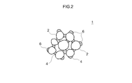
- FIG. 2 is a schematic diagram illustrating the composition of a composite particle.
- FIG. 3 is an exemplary schematic cross-sectional view of the structure of a lithium-ion secondary battery.
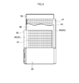
- FIG. 4 is a schematic diagram illustrating the structure of a wound electrode assembly.
- FIG. 5 is a graph illustrating the relationship between the numbers of rolling processes and the densities of negative electrode active material layers for negative electrodes manufactured by different methods.
- Lithium-ion secondary battery electrode(s) manufactured by the inventive method may suitably be used as a positive electrode and/or a negative electrode of a lithium-ion secondary battery, for example.
- FIG. 3 is a schematic cross-sectional view of the structure of a lithium-ion secondary battery 100.
- FIG. 4 is a schematic diagram illustrating the structure of an electrode assembly 20 serving as an electric power generating element to be provided in the lithium-ion secondary battery 100.
- the lithium-ion secondary battery 100 illustrated in FIG. 3 is merely an example of a lithium-ion secondary battery in which an electrode manufactured by the inventive method may be used. This means that the use of an electrode manufactured by the inventive method is not limited to a lithium-ion secondary battery such as the one illustrated in FIG. 3.
- the lithium-ion secondary battery 100 includes a battery case 10 and the electrode assembly 20.
- the electrode assembly 20 is what is called a “wound electrode assembly” provided by winding the electrode assembly 20 having an elongated shape.
- Battery Case The battery case 10 includes a case body 12 and a sealing plate 14.
- the case body 12 may have a hollow shape with an opening at its one surface.
- the case body 12 according to this embodiment has a flat rectangular parallelepiped shape with an opened surface that serves as the upper surface during normal use of the lithium-ion secondary battery 100.
- the case body 12 has a rectangular opening.
- the sealing plate 14 closes the opening of the case body 12.
- the sealing plate 14 may be a plate having a shape substantially conforming to the opening.
- the sealing plate 14 is joined to the peripheral edge of the opening of the case body 12 by, for example, welding, thus separating the inside of the battery case 10 from the outside so as to enclose the inside of the battery case 10.
- the battery case 10 is sealed with the sealing plate 14 after the electrode assembly 20 is housed in the case body 12.
- the electrode assembly 20 includes a positive electrode 30, a negative electrode 40, and first and second separators 50.
- the separators 50 are interposed between the positive and negative electrodes 30 and 40, thus insulating the positive and negative electrodes 30 and 40 from each other.
- the positive electrode 30, the negative electrode 40, and the separators 50 are stacked and wound so as to provide a “wound electrode assembly”.
- the electrode assembly 20 is, however, not limited to such an example.
- a plurality of the positive electrodes 30, a plurality of the negative electrodes 40, and the separators 50 may be stacked so as to provide a “stacked electrode assembly”.
- the positive electrode (positive electrode sheet) 30 includes a positive electrode collector 32, and a positive electrode active material layer 34.
- a metal foil suitable for the positive electrode 30 may preferably be used as the positive electrode collector 32.
- a strip-shaped aluminum foil with a predetermined width and a thickness of about 15 micrometers, for example, may be used as the positive electrode collector 32.
- a positive electrode collector portion 36 extends along widthwise one end of the positive electrode collector 32.
- the positive electrode active material layer 34 is provided on one surface or both surfaces of the positive electrode collector 32 except the positive electrode collector portion 36 of the positive electrode collector 32.
- the term “positive electrode collector portion 36” may refer to a portion of the positive electrode collector 32 where no positive electrode active material layer 34 is present.
- the mass percentage of the positive electrode active materials in the entire positive electrode active material layer 34 is typically about 50% or more, preferably between about 50% and about 95% inclusive, and more preferably between about 70% and about 95% inclusive.
- the mass percentage of the conductive material in the positive electrode active material layer 34 is typically between about 0.1% and about 20% inclusive, preferably between about 1% and about 15% inclusive, more preferably between about 2% and about 10% inclusive, and even more preferably between about 3% and about 7% inclusive relative to 100 mass% of the positive electrode active materials.
- the mass percentage of the binder in the positive electrode active material layer 34 is typically between about 0.01% and about 10% inclusive, preferably between about 0.1% and about 7% inclusive, and more preferably between about 1% and about 5% inclusive relative to 100 mass% of the positive electrode active materials.
- binders suitably used in forming composite particles (which will be described below) include a polyvinylidene fluoride (PVdF), polytetrafluoroethylene (PTFE), a tetrafluoroethylene-hexafluoropropylene copolymer (FEP), polyvinyl alcohol (PVA), a vinyl acetate copolymer, a styrene-butadiene rubber (SBR), a polyethylene oxide (PEO), and an acrylic polymer.
- PVdF polyvinylidene fluoride
- PTFE polytetrafluoroethylene
- FEP tetrafluoroethylene-hexafluoropropylene copolymer
- PVA polyvinyl alcohol
- SBR styrene-butadiene rubber
- PEO polyethylene oxide
- acrylic polymer any of various polymer materials which functions as a binder or thickener may optionally be used in combination with one or more of these substances.
- FIG. 2 is a schematic diagram illustrating the composition of a composite particle 1 according to the present embodiment.
- the composite particle 1 includes at least one particulate active material 2, and a binder 4.
- the binder 4 in particulate form, for example, may adhere to the surface of the active material 2.
- the composite particle 1 typically includes a plurality of particulate active materials 2.
- the binder 4 in particulate form may adhere to the surface of each active material 2, and the active materials 2 may be bonded to each other with the binder 4.
- the binder 4 does not cover the entire surface of each active material 2.
- the composite particle 1 preferably includes the binder 4 such that uneven local distribution of the binder 4 in the interior and on the outer surface of the composite particle 1 does not occur.
- the composite particle 1 preferably includes the binder 4 such that the binder 4 is distributed substantially uniformly in the interior and on the outer surface of the composite particle 1.
- the composite particle 1 may further include a conductive material 6.
- the composite particle 1 includes the conductive material 6, the conductive material 6 is preferably distributed mainly in the binder 4 as illustrated in FIG. 2.
- the composite particle 1 is provided in a suitable manner.
- the conductive material 6 may be distributed in the binder 4 in advance so that the binder 4, containing the conductive material 6, and the active materials 2 form the composite particle 1.
- the binder 4 may be present in any form, such as fiber form or particulate form.
- the binder 4 is preferably present in particulate form.
- the particle size of the composite particle 1 is not limited to any particular particle size.
- the composite particle 1 preferably has an average particle size (D50) of about 5 micrometers to about 100 micrometers, and more preferably has an average particle size (D50) of about 5 micrometers to about 60 micrometers.
- the positive and negative electrode collector portions 36 and 46 protruded from the separators 50, are brought together along the direction perpendicular to the winding axis WL, for example, and are respectively connected, by welding, for example, to an extremity 64 of a positive inner terminal 62 and an extremity 74 of a negative inner terminal 72 which are provided inside the battery case 10 and under the sealing plate 14.
- the positive and negative electrode collector portions 36 and 46 are respectively electrically connected to the positive and negative electrode external connection terminals 60 and 70 of the sealing plate 14 through the inner terminals 62 and 72.
- the electrode assembly 20 is housed in the battery case 10, with the electrode assembly 20 fixed to the sealing plate 14.
- the lithium ions pass through the separators 50 and move to the negative electrode 40 via the non-aqueous electrolyte solution.
- the lithium ions in the non-aqueous electrolyte solution are captured by the negative electrode active materials of the negative electrode active material layer 44, and thus stored in the negative electrode 40.
- lithium ions move from the negative electrode 40 to the positive electrode 30 in the electrode assembly 20. More specifically, lithium ions are released from the negative electrode active materials of the negative electrode active material layer 44 into the non-aqueous electrolyte solution.
- the lithium ions pass through the separators 50 and move to the positive electrode 30 via the non-aqueous electrolyte solution.
- the lithium ions in the non-aqueous electrolyte solution are captured by the positive electrode active materials of the positive electrode active material layer 34, and thus stored in the positive electrode 30. Connecting an external load between the positive and negative electrode external connection terminals 60 and 70 enables power to be drawn from the lithium-ion secondary battery 100.
- FIG. 1 is a schematic diagram illustrating manufacturing steps included in the inventive electrode manufacturing method.
- the inventive method for manufacturing the electrode 40 (or 30) includes: (1) supplying the composite particles 1, each containing the active materials 2 and the binder 4, onto the sheet collector 42 (or 32); and (2) rolling the composite particles 1 supplied onto the collector 42 (or 32) to form the active material layer 44 (or 34).
- Step (2) includes: a first rolling sub-step (2-1) involving first rolling; and a second rolling sub-step (2-2) to be performed after the first rolling sub-step.
- a predetermined amount of the composite particles 1 is supplied onto the collector 42 (or 32) as the collector 42 (or 32) is conveyed.
- the composite particles 1 fall on the collector 42 (or 32) from the feeder F through a sifter.
- the composite particles 1 may be supplied continuously or intermittently from the feeder F.
- the composite particles 1 may be supplied across the entire width of the collector 42 (or 32) perpendicular to the length thereof, or across a portion of the width of the collector 42 (or 32), such as a central portion of the collector 42 (or 32).
- the composite particles 1 supplied onto the collector 42 (or 32) are flattened with a squeegee S.
- the composite particles 1 are preferably flattened with the squeegee S such that the composite particles 1 are distributed uniformly across the surface of the collector 42 (or 32).
- the position of the squeegee S from the surface of the collector 42 (or 32) may be vertically adjustable.
- the squeegee S adjustable in position is able to remove an excessive amount of the composite particles 1 supplied onto the surface of the collector 42 (or 32). Flattening the composite particles 1 using the squeegee S in this manner provides a layer of the composite particles 1, with a substantially uniform weight per unit area of the composite particles 1 on the collector 42 (or 32).
- Rolling Step the composite particles 1 supplied onto the collector 42 (or 32) are rolled into the active material layer 44 (or 34).
- This rolling step is multi-step rolling involving rolling the composite particles 1 twice or more, not single-step rolling involving rolling the composite particles 1 just once.
- the first rolling sub-step of the multi-step rolling involves performing the first rolling.
- the second rolling sub-step involves rolling to be performed after the first rolling sub-step.
- the first rolling sub-step includes subjecting the layer of the composite particles 1 supplied onto the collector 42 (or 32) to the first rolling.
- the first rolling is characterized by the use of a pair of rubber rolls R1 disposed in balance with a predetermined distance (gap) therebetween.
- a rubber material constituting the surfaces of the rolls R1 lightly presses the layer of the composite particles 1.
- the composite particles 1 that have just been supplied from the feeder F or have been flattened with the squeegee S are in a naturally packed state, and are relatively lightly pressed by this rolling. This fills interstices between the composite particles 1 without causing cracks in the composite particles 1, thus increasing the density of the layer of the composite particles 1.
- the active materials 2 contained in the composite particles 1 may crack. Cracking in the active materials 2 increases the specific surface area of the active materials 2. The increase in the specific surface area of the active materials 2 in turn may lead to degradation in storage characteristics of the resulting lithium-ion secondary battery 100, especially at high temperature. In terms of the storage characteristics of the lithium-ion secondary battery 100, cracking in the active materials 2 is a phenomenon that should be avoided. Cracking in the active materials 2 is likely to occur particularly when the crystalline structures of the active materials 2 are layered or when substances constituting the active materials 2 have cleavability.
- Rolling in the first rolling sub-step may be performed only once, or may be performed more than once until the active material layer has a predetermined density.
- a target density for the first rolling sub-step may be decided in consideration of a final target density and the extent of rolling in the second rolling sub-step (which will be described below), for example.
- the target density for the first rolling sub-step is preferably between about 110% and about 200% inclusive and more preferably between about 120% and about 180% inclusive relative to the initial density, for example.
- the target density for the first rolling sub-step which is below 110% relative to the initial density is not preferable, because such a density may cause the composite particles 1, which is in a packed state resulting from a substantially free fall, to come off or slide down, making it impossible to provide a stable layer (or filmy layer).
- the target density for the first rolling sub-step which is higher than 200% relative to the initial density is also not preferable, because such a density may cause cracking in the active materials 2 as mentioned above.
- the term “initial density” refers to the density of an active material layer prior to the first rolling sub-step.
- the term “initial density” may refer to the bulk density of the composite particles 1 supplied onto the collector 42 (or 32) and flattened with the squeegee S.
- the second rolling sub-step includes rolling to be performed after the first rolling sub-step.
- the layer of the composite particles 1 is rolled with a pair of reduction rolls R21 and a pair of reduction rolls R22, each disposed in balance with a predetermined distance (gap) therebetween.
- Any material may be used for the reduction rolls R21 and R22 employed in the second rolling sub-step, which means that various reduction rolls R21 and R22 capable of achieving the target density of the active material layer 44 (or 34) may be used.
- preferred examples of the reduction rolls R21 and R22 include metal rolls whose rolling surfaces are composed of a metal material.
- rolling may be performed only once, or may be performed more than once until the active material layer 44 (or 34) has a target density.
- Rolling in the second rolling sub-step is preferably performed twice or more with the use of the pairs of reduction rolls R21 and R22. This sufficiently increases the density of the active material layer 44 (or 34) while reducing cracking in the active materials 2, even with the use of the reduction rolls composed of a material other than rubber. Consequently, these steps make it possible to manufacture the electrode 40 (or 30) including the high density active material layer 44 (or 34) that enables the resulting battery to offer high storage characteristics.
- the manufacturing method disclosed herein involves supplying the composite particles 1 in powder form onto the collector 42 (or 32), and then rolling the composite particles 1.
- a conventional method slurry prepared by dispersing the composite particles 1 in a solvent is supplied onto the collector 42 (or 32), dried, and then rolled.
- the inventive method requires a large pressure at the time of rolling.
- the inventive method requires a larger pressure in order to achieve the target density of the active material layer 44 (or 34).
- the method disclosed herein involves applying a large pressure to the layer of the composite particles 1 by performing rolling in multiple steps. This enables the density of the active material layer 44 (or 34) to reach a desired high value while reducing cracking in the active materials 2.
- the pairs of reduction rolls R21 and R22 may be porous or suction rolls, for example, and may more preferably be porous or suction rolls composed of ceramic or metal.
- the term “porous roll” may refer to a roll composed of a porous material, for example, or a roll whose surface has microscopic asperities or through holes provided by any of various processes, such as texturing (see JP 2012-216285 A, for example). Such a porous roll has enhanced gripping force and following ability at its surface. Thus, such a porous roll is capable of rolling and conveying an object to be rolled, without causing the object to slide over the roll surface, for example.
- suction roll may refer to a roll whose roll surface is provided with a large number of micropores in communication with a pressure regulating path inside the roll so as to be able to suck an object to be rolled.
- the pressure regulating path of the suction roll is connected with, for example, a negative pressure source so as to enable the suction roll to suck the object to the roll surface.
- a suction roll is capable of rolling and conveying the object without causing the object to slide over the roll surface, while sucking the object to the roll surface.
- suction roll may refer to a hollow (or typically cylindrical), porous roll that is composed of a porous material or a material whose surface is provided with a large number of microscopic through holes, and that internally includes a hollow portion in communication with a pressure regulator so as to suck an object to be rolled (see JP 03-57159 A, for example).
- the hollow portion of the suction roll is connected with, for example, a negative pressure source, thus enabling the suction roll to suck the object to the roll surface.
- such a suction roll used at least as the reduction roll that comes into contact with the collector is capable of rolling and conveying the electrode collector without causing the collector to slide over the roll surface even at high speed, while sucking the rolled collector to the roll surface.
- such porous and suction rolls used at least as the reduction rolls that come into contact with the active material layer are capable of rolling the composite particles 1 while sucking the composite particles 1.
- the suction roll preferentially sucks an excessive portion of the composite particles 1, thus enabling the composite particles 1 held uniformly on the surface of the suction roll to be rolled.
- the state of stacking the composite particles 1 are uniformized , which further reduces variations in weight per unit area of the active materials.
- the porous and suction rolls are typically conveying rolls that are conventionally used to convey an organic polymer film in a wrinkle-free manner.
- the manufacturing method disclosed herein is novel in that such conveying rolls are used to further increase the quality of rolling.
- the known weight of the collector 42 (or 32) is subtracted from the measured weight, thus calculating the weight per unit area of the active material layer 44 (or 34).
- the height (or thickness) of the active material layer 44 (or 34) may be measured with, for example, a position controller for the vertical position of the squeegee S so as to calculate the density of the active material layer before the first rolling sub-step (i.e., the initial density of the active material layer).
- scaly natural graphite was shaped into a sphere, thus preparing spherical graphite (with an average particle size of 30micrometers) as negative electrode active materials.
- the spherical graphite and an acrylic resin, serving as a binder, were mixed such that the mass ratio between these materials was 92.5: 7.5.
- this mixture was introduced with a small amount of water into a dry particle composing machine (e.g., Nobilta NOB-130 produced by HOSOKAWA MICRON CORPORATION), where a disperser was operated at 3 kW to carry out mixing for about 10 hours, thus providing composite particles (granulated particles) with an average particle size of about 60 micrometers.
- a dry particle composing machine e.g., Nobilta NOB-130 produced by HOSOKAWA MICRON CORPORATION
- Exemplary Method 2 Negative electrode sheets were fabricated similarly to Exemplary Method 1 except that metal rolls were used instead of the rubber rolls in the first rolling step. In other words, rolling was performed three times using the metal rolls to fabricate the negative electrode sheets with the three different densities.
- Table 1 indicates actual final densities (%) relative to the initial density and specific surface areas which were measured for the negative electrode active material layers of the negative electrode sheets fabricated as described above. Note that the specific surface areas were measured by BET method.
- FIG. 5 illustrates the relationship between the numbers of rolling processes and the electrode densities of the negative electrode active material layers relative to the initial density, which were obtained by Exemplary Methods 1 to 3, when the final target density was set at 212%. Note that Table 1 indicates average values obtained for 10 negative electrode sheets for measurement which were cut from each negative electrode sheet manufactured for a lithium secondary battery described below.
- the weight per unit area of the composite particles was determined by in-line measurement, and the extent of rolling (i.e., the inter-roll gap) was decided on the basis of the measured weight per unit area, so that there were only slight variations in the measurement values among the 10 negative electrode sheets for measurement.
- LiNi 1/3 Co 1/3 Mn 1/3 O 2 powder positive electrode active materials
- AB conductive material
- PVdF binder
- NMP solvent
- comparisons between Exemplary Methods 2 and 3 indicate that the specific surface areas of the active materials obtained by multi-step rolling using metal rolls are smaller than those obtained by conventional single-step press-rolling using metal rolls, although the electrode densities are substantially equal.
- An increase in the specific surface area of the negative electrode active material layer caused by rolling may be due to cracking in the active materials.
- multi-step press-rolling increases the density of the electrode while preventing cracking in the active materials.
- Comparisons between Exemplary Methods 1 and 2 indicate that the increase in the specific surface area resulting from rolling using rubber rolls is smaller than that resulting from rolling using metal rolls. We thus determined that cracking in the active materials during rolling was further reduced when rolling was performed using rubber rolls.
Landscapes
- Chemical & Material Sciences (AREA)
- Engineering & Computer Science (AREA)
- Manufacturing & Machinery (AREA)
- Chemical Kinetics & Catalysis (AREA)
- Electrochemistry (AREA)
- General Chemical & Material Sciences (AREA)
- Materials Engineering (AREA)
- Dispersion Chemistry (AREA)
- Battery Electrode And Active Subsutance (AREA)
Abstract
Description
[PTL 2]Japanese Patent Application Publication No. 2003-317707
Unfortunately, raising pressure during the rolling step or pressurizing step causes cracking in the active material particles. Such cracking may disadvantageously lead to degradation in storage characteristics of a resulting battery, for example. Significantly increasing the tap density of active material particles is difficult, which may make it hard for such active material particles to sufficiently contribute to higher capacity.
Accordingly, the objective of the present invention is to provide a method of manufacturing an electrode for a lithium-ion secondary battery that enables high capacity without any degradation in storage characteristics.
This embodiment makes it possible to uniformly supply a suitable amount of the composite particles onto the collector prior to the rolling in the first rolling sub-step. Consequently, this method enables manufacture of an electrode while preventing variations in the amount of the composite particles per unit area (i.e., the weight per unit area of the composite particles).
This embodiment makes it possible to supply a more suitable amount of the composite particles onto the collector on a per unit area basis. Consequently, this method enables manufacture of an electrode with a capacity (or a weight per unit area) suitable for a desired electrode structure.
This embodiment further increases the density of the composite particles in the active material layer while preventing cracking in the active materials.
In this embodiment, rubber rolls are used to perform the first rolling, thus relatively softening the impact on the composite particles, and increasing the density of the composite particles while preventing cracking in the active materials in the composite particles.
This embodiment makes it possible to form the active material layer whose quality of weight per unit area is high while more effectively preventing cracking in the active materials.
This embodiment enables the composite particles to firmly bond to each other to form the active material layer.
This embodiment enables, for example, in-line control of the weight per unit area of the active materials even in manufacturing an elongated electrode, thus making it possible to stably manufacture a high-quality electrode.
FIG. 3 is a schematic cross-sectional view of the structure of a lithium-ion
Battery Case
The
As illustrated in FIG. 4, the
The positive electrode (positive electrode sheet) 30 includes a
The term "average particle size" used herein represents the particle size (D50) equivalent to a cumulative 50% of the particle size distribution of a standard volume measured by a particle size distribution measurement based on conventional laser diffraction and light-scattering methods.
The thickness of the positive electrode
The negative electrode (negative electrode sheet) 40 includes a
The negative electrode
The binders serve to bond particles of materials contained in the positive and negative electrode active material layers 34 and 44, such as the electrode active materials and conductive materials, and to bond these particles to the positive and
Specifically, preferred examples of the binders suitably used in forming composite particles (which will be described below) include a polyvinylidene fluoride (PVdF), polytetrafluoroethylene (PTFE), a tetrafluoroethylene-hexafluoropropylene copolymer (FEP), polyvinyl alcohol (PVA), a vinyl acetate copolymer, a styrene-butadiene rubber (SBR), a polyethylene oxide (PEO), and an acrylic polymer. Any of various polymer materials which functions as a binder or thickener may optionally be used in combination with one or more of these substances. Preferred examples of such a polymer material include cellulose polymers, such as carboxymethyl cellulose (CMC) and hydroxypropyl methylcellulose (HPMC).
The active materials and binders to be contained in the positive and negative electrode active material layers 34 and 44 may be formed into composite particles in advance, and these composite particles may be bonded so as to provide the active material layers 34 and 44. When the active material layers 34 and 44 further contain the conductive materials, these composite particles may further contain the conductive materials.
FIG. 2 is a schematic diagram illustrating the composition of a
The particle size of the
As illustrated in FIGS. 3 and 4, the
Although not illustrated, each
In the example illustrated in FIG. 4, the
Any of various electrolytes conventionally used for a lithium-ion secondary battery or its equivalent may be used as the electrolyte. Typically, an electrolyte may be used in a form of a non-aqueous electrolyte solution that prepared by dissolving the electrolyte in a suitable non-aqueous solvent. Examples of the non-aqueous solvent include organic solvents, such as: ethylene carbonate; propylene carbonate; dimethyl carbonate; diethyl carbonate; ethyl methyl carbonate; 1, 2-dimethoxyethane; 1, 2-diethoxyethane; tetrahydrofuran; and 1, 3-dioxolane. As the non-aqueous solvent, one type of such organic solvents may be used alone, or two or more types of such organic solvents may be used in combination. Examples of the electrolyte (which may also be referred to as a “supporting electrolyte”) to be used include lithium salts, such as LiPF6, LiBF4, LiAsF6, LiCF3SO3, LiC4F9SO3, LiN(CF3SO2)2, and LiC(CF3SO2)3. One example of the non-aqueous electrolyte solution is prepared by dissolving LiPF6 at a concentration of about 1 mol/L in a solvent mixture of ethylene carbonate and diethyl carbonate (which are mixed at a mass ratio of 1: 1, for example). Instead of the non-aqueous electrolyte solution, a highly ionically conductive gel or a solid electrolyte may be used.
The lithium-ion
First, when the lithium-ion
When the lithium-ion
FIG. 1 is a schematic diagram illustrating manufacturing steps included in the inventive electrode manufacturing method. The inventive method for manufacturing the electrode 40 (or 30) includes:
(1) supplying the
(2) rolling the
Step (2) includes:
a first rolling sub-step (2-1) involving first rolling; and
a second rolling sub-step (2-2) to be performed after the first rolling sub-step.
These steps will be described in more detail below.
In Composite Particle SupplyingStep, the
In Rolling Step, the
The first rolling sub-step includes subjecting the layer of the
As used herein, the term “initial density” refers to the density of an active material layer prior to the first rolling sub-step. For example, the term “initial density” may refer to the bulk density of the
The second rolling sub-step includes rolling to be performed after the first rolling sub-step. In the second rolling sub-step, the layer of the
The term “suction roll” may refer to a hollow (or typically cylindrical), porous roll that is composed of a porous material or a material whose surface is provided with a large number of microscopic through holes, and that internally includes a hollow portion in communication with a pressure regulator so as to suck an object to be rolled (see JP 03-57159 A, for example). The hollow portion of the suction roll is connected with, for example, a negative pressure source, thus enabling the suction roll to suck the object to the roll surface.
Furthermore, such porous and suction rolls used at least as the reduction rolls that come into contact with the active material layer are capable of rolling the
The pressure regulator connected to the suction roll (or the porous roll) may be configured not only to depressurize the hollow portion of the suction roll (or the porous roll) so as to suck an object to be rolled, but also to pressurize the hollow portion. Thus, the electrode (i.e., the electrode collector and/or active material layer) sucked to the roll surface through the through holes of the suction roll (or the porous roll), for example, is detached (separated) from the roll surface smoothly.
Note that heat-rolling is not limited to heating the reduction rolls during rolling. The layer of the
This allows the
The above-described electrode manufacturing method is also suitably employed to manufacture the electrode 40 (or 30) including the active material layer 44 (or 34) that contains, for example, the
Negative electrode sheets for lithium-ion secondary batteries were fabricated by
First, scaly natural graphite was shaped into a sphere, thus preparing spherical graphite (with an average particle size of 30micrometers) as negative electrode active materials. The spherical graphite and an acrylic resin, serving as a binder, were mixed such that the mass ratio between these materials was 92.5: 7.5. Then, this mixture was introduced with a small amount of water into a dry particle composing machine (e.g., Nobilta NOB-130 produced by HOSOKAWA MICRON CORPORATION), where a disperser was operated at 3 kW to carry out mixing for about 10 hours, thus providing composite particles (granulated particles) with an average particle size of about 60 micrometers.
First Rolling Step
Subsequently, the composite particles were stored in a powder feeder, and supplied at a predetermined supply rate onto an approximately 10 micrometers thick, elongated copper foil (negative electrode collector) transported on a conveyor. Using a squeegee equipped with a height sensor, an excessive amount of the composite particles supplied onto the negative electrode collector was scraped off, so that the height of the composite particles was made uniform across the width of the negative electrode collector. Then, the composite particles were conveyed, together with the negative electrode collector, to a first rolling section. While the composite particles were conveyed, the weight per unit area of the composite particles supplied onto the negative electrode collector was measured with an in-line weight per unit area measuring device. The bulk density of the composite particles, calculated from the measured weight per unit area and the height of the squeegee, was determined to be an initial density. The initial density was measured each time the negative electrode collector was conveyed by a predetermined length.
In the second rolling section, a pair of metal rolls, serving as press rolls, was installed. In a third rolling section downstream of the second rolling section, another pair of metal rolls, serving as press rolls, was installed. The distance (gap) between the metal rolls in the second rolling section and the distance (gap) between the metal rolls in the third rolling section were each adjusted when necessary on the basis of the initial density measured in advance at a predetermined position of the negative electrode collector, so as to enable the density of the active material layer to reach a final target density. In the second rolling step, the composite particles conveyed together with the negative electrode collector were rolled twice such that the final target density was reached, i.e., the density was increased by 182%, 212%, or 240% relative to the initial density. We determined that the composite particles, which had passed through the second rolling section, were bonded to each other to form the negative electrode active material layer. We also determined that the negative electrode active material layer was combined with the negative electrode collector. Thus, negative electrode sheets with the three different densities were manufactured. Each negative electrode sheet was cut into a predetermined size and used to make a secondary battery described below.
Negative electrode sheets were fabricated similarly to
Negative electrode sheets were fabricated similarly to
Table 1 indicates actual final densities (%) relative to the initial density and specific surface areas which were measured for the negative electrode active material layers of the negative electrode sheets fabricated as described above. Note that the specific surface areas were measured by BET method. FIG. 5 illustrates the relationship between the numbers of rolling processes and the electrode densities of the negative electrode active material layers relative to the initial density, which were obtained by
Fabrication of Positive Electrode Sheet
Next, LiNi1/3Co1/3Mn1/3O2 powder (positive electrode active materials), AB (conductive material), and PVdF (binder) were mixed at a mass ratio of 94: 3: 3 with NMP (solvent) to prepare a composition in paste form. This composition was applied to an approximately 15 micrometers thick, elongated aluminum foil (positive electrode collector), dried, and then pressed into a positive electrode sheet by a flat press.
The electrode assembly was housed in a rectangular battery case composed of an Al alloy, and a non-aqueous electrolyte solution was injected into the battery case. The non-aqueous electrolyte solution used was prepared as follows: LiPF6 (electrolyte) was dissolved at a concentration of about 1 mol/L in a solvent mixture containing ethylene carbonate (EC), ethyl methyl carbonate (EMC), and dimethyl carbonate (DMC) at a volume ratio of 3: 4: 3. Then, a lid was attached and welded to an opening of the battery case, thus providing a lithium secondary battery of
The lithium secondary batteries of
(1) Each battery was charged with a constant current at a rate of 1 C (40 A) until 4.1 V was reached;
(2) Charging was suspended for 5 minutes;
(3) Each battery was discharged with a constant current at a rate of 1 C (40 A) until 3.0 V was reached; and
(4) Discharging was suspended for 5 minutes.
(1) Each battery was charged with a constant current at a rate of 1 C (40 A) until 4.1 V was reached, and then charged with a constant voltage until a rate of 0.1 C (4C) was reached;
(2) Charging was suspended for 5 minutes;
(3) Each battery was discharged with a constant current at a rate of 1 C (40 A) until 3.0 V was reached, and then discharged with a constant voltage until a rate of 0.1 C (4A) was reached; and
(4) Discharging was suspended for 5 minutes.
The resulting discharge capacity (i.e., a total sum of the products of current and voltage values) was determined to be the initial capacity. We determined that the batteries fabricated each had an initial capacity of about 24 Ah, and thus there was little difference among the initial capacities of the batteries.
Storage Characteristics (%) = (Post-Storage Capacity) / (Initial Capacity) x 100
The storage characteristics calculated are listed in Table 1 below.

Comparisons between
2 active material
4 binder
6 conductive material
10 battery case
12 case body
14 sealing plate
20 electrode assembly
30 positive electrode (positive electrode sheet)
32 positive electrode collector
34 positive electrode active material layer
36 positive electrode collector portion
40 negative electrode (negative electrode sheet)
42 negative electrode collector
44 negative electrode active material layer
46 negative electrode collector portion
50 separator
60 positive electrode external connection terminal
70 negative electrode external connection terminal
62, 72 inner terminal
64, 74 extremity
100 lithium-ion secondary battery
Claims (7)
- A method of manufacturing a lithium-ion secondary battery electrode, the method comprising:
supplying composite particles, each containing an active material and a binder, onto a sheet collector; and
rolling the composite particles supplied onto the collector to form an active material layer, wherein
the rolling step includes a first rolling sub-step involving first rolling, and a second rolling sub-step to be performed after the first rolling sub-step. - The method according to claim 1, further comprising:
flattening the composite particles, supplied onto the collector, using a squeegee, wherein the flattening step precedes the first rolling sub-step. - The method according to claim 2, further comprising:
controlling a vertical position of the squeegee, thus adjusting an amount of the composite particles supplied onto the collector. - The method according to any one of claims 1 to 3, wherein rolling is performed more than once in the second rolling sub-step.
- The method according to any one of claims 1 to 4, wherein rubber rolls are used in the first rolling sub-step.
- The method according to any one of claims 1 to 5, wherein at least one of the first rolling sub-step and the second rolling sub-step is heat-rolling.
- The method according to any one of claims 1 to 6, further comprising: measuring a weight per unit area of the composite particles supplied onto the collector, and adjusting an extent of the rolling in the first rolling sub-step and/or the second rolling sub-step on a basis of the measured weight per unit area, wherein
the measuring and adjusting step is performed at any point between the supplying step and the second rolling sub-step.
Priority Applications (3)
| Application Number | Priority Date | Filing Date | Title |
|---|---|---|---|
| CN201580048571.5A CN106804115B (en) | 2014-09-12 | 2015-09-08 | Method for manufacturing lithium ion secondary battery electrode |
| KR1020177009467A KR101889240B1 (en) | 2014-09-12 | 2015-09-08 | Method of manufacturing lithium-ion secondary battery electrode |
| US15/510,274 US10431807B2 (en) | 2014-09-12 | 2015-09-08 | Method of manufacturing lithium-ion secondary battery electrode |
Applications Claiming Priority (2)
| Application Number | Priority Date | Filing Date | Title |
|---|---|---|---|
| JP2014187015A JP6067636B2 (en) | 2014-09-12 | 2014-09-12 | Method for producing electrode for lithium ion secondary battery |
| JP2014-187015 | 2014-09-12 |
Publications (1)
| Publication Number | Publication Date |
|---|---|
| WO2016038889A1 true WO2016038889A1 (en) | 2016-03-17 |
Family
ID=54251691
Family Applications (1)
| Application Number | Title | Priority Date | Filing Date |
|---|---|---|---|
| PCT/JP2015/004576 Ceased WO2016038889A1 (en) | 2014-09-12 | 2015-09-08 | Method of manufacturing lithium-ion secondary battery electrode |
Country Status (5)
| Country | Link |
|---|---|
| US (1) | US10431807B2 (en) |
| JP (1) | JP6067636B2 (en) |
| KR (1) | KR101889240B1 (en) |
| CN (1) | CN106804115B (en) |
| WO (1) | WO2016038889A1 (en) |
Cited By (4)
| Publication number | Priority date | Publication date | Assignee | Title |
|---|---|---|---|---|
| US20160181651A1 (en) * | 2014-12-19 | 2016-06-23 | Toyota Jidosha Kabushiki Kaisha | Apparatus for manufacturing electrode for lithium ion secondary battery |
| CN107230775A (en) * | 2016-03-25 | 2017-10-03 | 株式会社斯库林集团 | Matrix material processing unit and matrix material processing method |
| EP3923375A4 (en) * | 2019-02-07 | 2022-03-30 | NISSAN MOTOR Co., Ltd. | Battery electrode manufacturing method |
| WO2023204774A1 (en) * | 2022-04-21 | 2023-10-26 | İzmi̇r Eği̇ti̇m Sağlik Sanayi̇ Yatirim A.Ş. | Thermoplastic based composite material used for cathode in secondary batteries |
Families Citing this family (42)
| Publication number | Priority date | Publication date | Assignee | Title |
|---|---|---|---|---|
| US10468666B2 (en) * | 2016-09-29 | 2019-11-05 | Nissan North America, Inc. | Rolling press and conductivity detector for the manufacture of lithium-ion battery electrodes |
| JP6782645B2 (en) * | 2017-02-01 | 2020-11-11 | 株式会社エンビジョンAescジャパン | Electrode sheet transfer device |
| US11283058B2 (en) * | 2017-03-22 | 2022-03-22 | Lg Energy Solution, Ltd. | Method of preparing slurry composition for secondary battery positive electrode, positive electrode for secondary battery prepared by using the same, and lithium secondary battery including the positive electrode |
| CN107732138B (en) * | 2017-08-28 | 2020-08-28 | 惠州金源精密自动化设备有限公司 | Dry powder anode film laminating machine |
| JP7022539B2 (en) * | 2017-09-07 | 2022-02-18 | 三洋化成工業株式会社 | Method for manufacturing electrodes for lithium-ion batteries and equipment for manufacturing electrodes for lithium-ion batteries |
| JP2019175721A (en) * | 2018-03-29 | 2019-10-10 | 三洋電機株式会社 | Manufacturing method for positive electrode for non-aqueous electrolyte secondary battery and manufacturing method for non-aqueous electrolyte secondary battery |
| CN109103428A (en) * | 2018-08-02 | 2018-12-28 | 武汉艾特米克超能新材料科技有限公司 | A kind of alkali metal battery cathode and preparation method thereof and battery |
| KR102143643B1 (en) * | 2018-08-24 | 2020-08-11 | 주식회사 엘지화학 | Manufacturing apparatus of electrode or solid electrolyte for all-solid-state battery |
| CN109910337B (en) * | 2019-03-19 | 2023-07-21 | 上海神力科技有限公司 | A high-speed production method of vertical lamellar structure flexible graphite pole plate |
| US11522215B2 (en) | 2019-03-22 | 2022-12-06 | Toyota Jidosha Kabushiki Kaisha | All-solid-state battery production method and all-solid-state battery |
| WO2020262649A1 (en) | 2019-06-28 | 2020-12-30 | 富士フイルム株式会社 | Method for producing molding for electrode |
| WO2021033521A1 (en) * | 2019-08-19 | 2021-02-25 | 富士フイルム株式会社 | Method for manufacturing electrode molding |
| DE102019122226A1 (en) * | 2019-08-19 | 2021-02-25 | Bayerische Motoren Werke Aktiengesellschaft | Composite electrode for a lithium or lithium-ion battery and manufacturing process therefor |
| WO2021033689A1 (en) | 2019-08-19 | 2021-02-25 | 富士フイルム株式会社 | Electrode moulded body production method |
| EP4020613A4 (en) | 2019-08-19 | 2023-03-29 | FUJIFILM Corporation | Method for producing molded body for electrodes |
| JP2022023473A (en) * | 2020-07-27 | 2022-02-08 | Apb株式会社 | Lithium-ion secondary battery electrode manufacturing equipment and manufacturing method |
| KR102926748B1 (en) * | 2020-08-21 | 2026-02-11 | 주식회사 엘지에너지솔루션 | Method for rolling electrode |
| US20220069312A1 (en) * | 2020-08-26 | 2022-03-03 | GM Global Technology Operations LLC | Method and system to create variable densities within battery electrodes |
| JP7202348B2 (en) * | 2020-12-14 | 2023-01-11 | プライムプラネットエナジー&ソリューションズ株式会社 | Electrode sheet manufacturing method |
| JP7202347B2 (en) * | 2020-12-14 | 2023-01-11 | プライムプラネットエナジー&ソリューションズ株式会社 | Electrode sheet manufacturing method |
| CN113646933B (en) * | 2020-12-31 | 2024-02-13 | 宁德新能源科技有限公司 | Pole pieces, electrochemical devices and electronic devices |
| JP7222002B2 (en) * | 2021-01-29 | 2023-02-14 | プライムプラネットエナジー&ソリューションズ株式会社 | Positive electrode active material composite particles, method for producing positive electrode plate, and method for producing positive electrode active material composite particles |
| JP7334201B2 (en) | 2021-03-01 | 2023-08-28 | プライムプラネットエナジー&ソリューションズ株式会社 | SECONDARY BATTERY ELECTRODE AND METHOD FOR MANUFACTURING SAME ELECTRODE |
| KR20220125929A (en) * | 2021-03-08 | 2022-09-15 | 현대자동차주식회사 | Method of manufacturing electrode for all-solid-state battery, and electrode for all-solid-state battery manufactured thereby |
| JP7268081B2 (en) * | 2021-04-28 | 2023-05-02 | プライムプラネットエナジー&ソリューションズ株式会社 | Electrode sheet manufacturing method |
| JP7324245B2 (en) * | 2021-05-25 | 2023-08-09 | プライムプラネットエナジー&ソリューションズ株式会社 | Electrode sheet manufacturing method |
| KR20230070867A (en) | 2021-11-15 | 2023-05-23 | 주식회사 엘지에너지솔루션 | Secondary cell rolling system and secondary cell defect prediction function method using the same |
| JPWO2023100973A1 (en) * | 2021-12-03 | 2023-06-08 | ||
| CN118302873A (en) * | 2021-12-03 | 2024-07-05 | 日本瑞翁株式会社 | Device for manufacturing electrode active material layer |
| JP7510912B2 (en) * | 2021-12-13 | 2024-07-04 | プライムアースEvエナジー株式会社 | Method for manufacturing electrode plate and method for manufacturing battery |
| KR102952946B1 (en) * | 2021-12-16 | 2026-04-14 | 주식회사 엘지에너지솔루션 | Apparatus and method for preparing positive electrode, and lithium secondary battery comprising the same |
| EP4310962B1 (en) * | 2021-12-24 | 2026-04-22 | Lg Energy Solution, Ltd. | Method for manufacturing cathode for lithium secondary battery, and cathode |
| KR102783069B1 (en) * | 2021-12-28 | 2025-03-19 | (주)테라시스 | Apparatus and method of manufacturing an electrode material, and electrode material manufactured through the same |
| US20250087656A1 (en) | 2022-01-31 | 2025-03-13 | Zeon Corporation | Method of producing electrode for lithium ion secondary battery, binder for lithium ion secondary battery electrode, electrode for lithium ion secondary battery, and lithium ion secondary battery |
| CN114464897B (en) * | 2022-02-11 | 2023-06-30 | 惠州亿纬锂能股份有限公司 | Method for improving high-temperature floating charge performance of lithium ion battery and lithium ion battery |
| DE102023200011A1 (en) * | 2023-01-03 | 2024-07-04 | Volkswagen Aktiengesellschaft | Device and method for producing an electrode |
| US20240396003A1 (en) * | 2023-05-27 | 2024-11-28 | Arizona Board Of Regents On Behalf Of Arizona State University | System and method for dry battery electrode fabrication via direct powder bed formation and compression |
| WO2025009098A1 (en) * | 2023-07-05 | 2025-01-09 | 日産自動車株式会社 | Method for producing electrode for secondary battery |
| WO2025142267A1 (en) * | 2023-12-25 | 2025-07-03 | 富士フイルム株式会社 | Method for producing molded body for electrodes |
| US12476238B2 (en) * | 2024-02-21 | 2025-11-18 | Lg Energy Solution, Ltd. | Methods for making solid state battery apparatus |
| JP2025140965A (en) * | 2024-03-15 | 2025-09-29 | 東レエンジニアリング株式会社 | Electrode manufacturing method and electrode manufacturing device |
| WO2026071205A1 (en) * | 2024-09-30 | 2026-04-02 | 富士フイルム株式会社 | Manufacturing method for electrode film and manufacturing device for electrode film |
Citations (8)
| Publication number | Priority date | Publication date | Assignee | Title |
|---|---|---|---|---|
| JPH0357159A (en) | 1989-07-25 | 1991-03-12 | Shin Kobe Electric Mach Co Ltd | Paste coating method |
| JP2002124252A (en) * | 2000-10-12 | 2002-04-26 | Yuasa Corp | Method for manufacturing electrode plate for storage battery |
| JP2003317707A (en) | 2002-04-26 | 2003-11-07 | Matsushita Electric Ind Co Ltd | Negative electrode for non-aqueous electrolyte secondary battery and method for producing the same |
| JP2005340188A (en) | 2004-04-28 | 2005-12-08 | Tdk Corp | Electrode, electrochemical device, and electrode manufacturing method |
| US20110269017A1 (en) * | 2009-01-26 | 2011-11-03 | Hiroyuki Sakamoto | Positive electrode for lithium secondary batteries and use thereof |
| JP2012216285A (en) | 2011-03-31 | 2012-11-08 | Sanyo Electric Co Ltd | Nonaqueous electrolyte secondary battery |
| JP2013077559A (en) * | 2011-09-14 | 2013-04-25 | Nippon Zeon Co Ltd | Method for manufacturing electrode for electrochemical element |
| JP2014107166A (en) * | 2012-11-28 | 2014-06-09 | Toyota Industries Corp | Manufacturing apparatus of electrode and manufacturing method of electrode |
Family Cites Families (20)
| Publication number | Priority date | Publication date | Assignee | Title |
|---|---|---|---|---|
| US3002834A (en) * | 1960-02-24 | 1961-10-03 | Yardney International Corp | Process for producing electrode plates |
| US4765598A (en) * | 1986-05-12 | 1988-08-23 | Energy Conversion Devices, Inc. | Apparatus for making electrode material from high hardness active materials |
| JPH04332467A (en) * | 1991-05-07 | 1992-11-19 | Matsushita Electric Ind Co Ltd | Device for manufacturing paste type pole plate for lead storage battery |
| WO1995029509A1 (en) * | 1994-04-20 | 1995-11-02 | Valence Technology, Inc. | Method for producing low porosity electrode |
| DE19916043A1 (en) * | 1999-04-09 | 2000-10-19 | Basf Ag | Composite body suitable for use as a lithium ion battery |
| JP2000331673A (en) * | 1999-05-24 | 2000-11-30 | Toshiba Battery Co Ltd | Manufacture of polymer lithium secondary battery |
| FR2822296A1 (en) * | 2001-03-19 | 2002-09-20 | Atofina | Separators and electroactive layers for lithium batteries, produced by shaping a microcomposite powder comprising a filler and a finely divided fluoropolymer |
| US20110165318A9 (en) * | 2004-04-02 | 2011-07-07 | Maxwell Technologies, Inc. | Electrode formation by lamination of particles onto a current collector |
| US20050241137A1 (en) | 2004-04-28 | 2005-11-03 | Tdk Corporation | Electrode, electrochemical device, and method of making electrode |
| CN100449824C (en) | 2005-10-24 | 2009-01-07 | 比亚迪股份有限公司 | Battery pole piece and preparation method of lithium ion secondary battery containing the pole piece |
| CN101207195A (en) | 2006-12-22 | 2008-06-25 | 比亚迪股份有限公司 | A kind of preparation method of battery pole piece |
| JP2008218134A (en) * | 2007-03-02 | 2008-09-18 | Matsushita Electric Ind Co Ltd | Electrode group manufacturing equipment |
| JP5842407B2 (en) * | 2011-06-28 | 2016-01-13 | トヨタ自動車株式会社 | Method for producing lithium ion secondary battery |
| US20140342225A1 (en) | 2011-09-14 | 2014-11-20 | Zeon Corporation | Electrode for electrochemical device |
| JP2013077560A (en) | 2011-09-14 | 2013-04-25 | Nippon Zeon Co Ltd | Method for manufacturing electrode for electrochemical element |
| JP2013065478A (en) * | 2011-09-19 | 2013-04-11 | Toyota Motor Corp | Method for manufacturing lithium ion secondary battery |
| JP5765574B2 (en) * | 2011-12-20 | 2015-08-19 | トヨタ自動車株式会社 | Secondary battery, method for producing the same, and method for producing negative electrode sheet used in the battery |
| US20150255795A1 (en) | 2012-09-28 | 2015-09-10 | Tdk Corporation | Lithium ion secondary battery |
| JP2015230747A (en) * | 2014-06-03 | 2015-12-21 | トヨタ自動車株式会社 | Electrode for lithium ion secondary battery |
| CN104009207B (en) * | 2014-06-16 | 2016-08-17 | 浙江金开来新能源科技有限公司 | A kind of lithium battery pole slice milling train realizing twice roll-in |
-
2014
- 2014-09-12 JP JP2014187015A patent/JP6067636B2/en active Active
-
2015
- 2015-09-08 WO PCT/JP2015/004576 patent/WO2016038889A1/en not_active Ceased
- 2015-09-08 US US15/510,274 patent/US10431807B2/en active Active
- 2015-09-08 CN CN201580048571.5A patent/CN106804115B/en active Active
- 2015-09-08 KR KR1020177009467A patent/KR101889240B1/en active Active
Patent Citations (8)
| Publication number | Priority date | Publication date | Assignee | Title |
|---|---|---|---|---|
| JPH0357159A (en) | 1989-07-25 | 1991-03-12 | Shin Kobe Electric Mach Co Ltd | Paste coating method |
| JP2002124252A (en) * | 2000-10-12 | 2002-04-26 | Yuasa Corp | Method for manufacturing electrode plate for storage battery |
| JP2003317707A (en) | 2002-04-26 | 2003-11-07 | Matsushita Electric Ind Co Ltd | Negative electrode for non-aqueous electrolyte secondary battery and method for producing the same |
| JP2005340188A (en) | 2004-04-28 | 2005-12-08 | Tdk Corp | Electrode, electrochemical device, and electrode manufacturing method |
| US20110269017A1 (en) * | 2009-01-26 | 2011-11-03 | Hiroyuki Sakamoto | Positive electrode for lithium secondary batteries and use thereof |
| JP2012216285A (en) | 2011-03-31 | 2012-11-08 | Sanyo Electric Co Ltd | Nonaqueous electrolyte secondary battery |
| JP2013077559A (en) * | 2011-09-14 | 2013-04-25 | Nippon Zeon Co Ltd | Method for manufacturing electrode for electrochemical element |
| JP2014107166A (en) * | 2012-11-28 | 2014-06-09 | Toyota Industries Corp | Manufacturing apparatus of electrode and manufacturing method of electrode |
Cited By (7)
| Publication number | Priority date | Publication date | Assignee | Title |
|---|---|---|---|---|
| US20160181651A1 (en) * | 2014-12-19 | 2016-06-23 | Toyota Jidosha Kabushiki Kaisha | Apparatus for manufacturing electrode for lithium ion secondary battery |
| US9960409B2 (en) * | 2014-12-19 | 2018-05-01 | Toyota Jidosha Kabushiki Kaisha | Apparatus for manufacturing electrode for lithium ion secondary battery |
| CN107230775A (en) * | 2016-03-25 | 2017-10-03 | 株式会社斯库林集团 | Matrix material processing unit and matrix material processing method |
| EP3923375A4 (en) * | 2019-02-07 | 2022-03-30 | NISSAN MOTOR Co., Ltd. | Battery electrode manufacturing method |
| US20220123274A1 (en) * | 2019-02-07 | 2022-04-21 | Nissan Motor Co., Ltd. | Method of manufacturing battery electrode |
| US12272811B2 (en) * | 2019-02-07 | 2025-04-08 | Nissan Motor Co., Ltd. | Method of manufacturing battery electrode |
| WO2023204774A1 (en) * | 2022-04-21 | 2023-10-26 | İzmi̇r Eği̇ti̇m Sağlik Sanayi̇ Yatirim A.Ş. | Thermoplastic based composite material used for cathode in secondary batteries |
Also Published As
| Publication number | Publication date |
|---|---|
| KR20170049583A (en) | 2017-05-10 |
| US10431807B2 (en) | 2019-10-01 |
| JP6067636B2 (en) | 2017-01-25 |
| JP2016062654A (en) | 2016-04-25 |
| CN106804115A (en) | 2017-06-06 |
| KR101889240B1 (en) | 2018-08-16 |
| US20170256781A1 (en) | 2017-09-07 |
| CN106804115B (en) | 2020-09-04 |
Similar Documents
| Publication | Publication Date | Title |
|---|---|---|
| US10431807B2 (en) | Method of manufacturing lithium-ion secondary battery electrode | |
| JP6142884B2 (en) | Method for producing non-aqueous electrolyte secondary battery | |
| KR100802870B1 (en) | Wound-type non-aqueous secondary battery and electrode plate used for this | |
| EP3226327B1 (en) | Method for manufacturing electrode for lithium ion secondary cell | |
| JP6057124B2 (en) | Secondary battery | |
| JP6380808B2 (en) | Method for manufacturing electrode for secondary battery | |
| JP7242120B2 (en) | Lithium secondary battery and manufacturing method thereof | |
| US9985274B2 (en) | Method of manufacturing lithium-ion secondary battery electrode sheet | |
| JP2015230748A (en) | Method of manufacturing electrode for lithium ion secondary battery | |
| EP4057388A1 (en) | Electrode for secondary battery and secondary battery including same | |
| JP2015230747A (en) | Electrode for lithium ion secondary battery | |
| WO2015173623A1 (en) | Method of manufacturing secondary battery | |
| CN107615528A (en) | Lithium ion secondary battery cathode active material and lithium rechargeable battery | |
| EP4053931A2 (en) | Secondary battery electrode and method for producing the electrode | |
| CN104078650A (en) | Electrode for non-aqueous electrolytic battery, non-aqueous electrolytic secondary battery, and battery pack | |
| US20200152969A1 (en) | Electrode, energy storage device, and method for manufacturing electrode | |
| US20220293905A1 (en) | Method of producing electrode for secondary battery | |
| JP6008188B2 (en) | Non-aqueous electrolyte secondary battery | |
| US12206092B2 (en) | Method for producing secondary battery electrode and method for producing secondary battery | |
| US12283684B2 (en) | Secondary battery electrode and method for producing the electrode | |
| JP7804081B2 (en) | Positive electrode for lithium secondary battery and method for producing same | |
| WO2025092701A1 (en) | Electrode sheet and preparation method therefor, and battery and electric system | |
| KR20240146599A (en) | Electrode plate for lithium secondary battery and lithium secondary battery comprising the same | |
| JP2025002061A (en) | Lithium ion secondary battery, negative electrode plate for lithium ion secondary battery, and manufacturing method for lithium ion secondary battery |
Legal Events
| Date | Code | Title | Description |
|---|---|---|---|
| 121 | Ep: the epo has been informed by wipo that ep was designated in this application |
Ref document number: 15775005 Country of ref document: EP Kind code of ref document: A1 |
|
| WWE | Wipo information: entry into national phase |
Ref document number: 15510274 Country of ref document: US |
|
| NENP | Non-entry into the national phase |
Ref country code: DE |
|
| ENP | Entry into the national phase |
Ref document number: 20177009467 Country of ref document: KR Kind code of ref document: A |
|
| 122 | Ep: pct application non-entry in european phase |
Ref document number: 15775005 Country of ref document: EP Kind code of ref document: A1 |