WO2016038652A1 - 熱交換器及び熱交換器の板状フィンの製造方法 - Google Patents
熱交換器及び熱交換器の板状フィンの製造方法 Download PDFInfo
- Publication number
- WO2016038652A1 WO2016038652A1 PCT/JP2014/073609 JP2014073609W WO2016038652A1 WO 2016038652 A1 WO2016038652 A1 WO 2016038652A1 JP 2014073609 W JP2014073609 W JP 2014073609W WO 2016038652 A1 WO2016038652 A1 WO 2016038652A1
- Authority
- WO
- WIPO (PCT)
- Prior art keywords
- plate
- fin
- heat exchanger
- heat transfer
- transfer tube
- Prior art date
Links
Images


Classifications
-
- F—MECHANICAL ENGINEERING; LIGHTING; HEATING; WEAPONS; BLASTING
- F28—HEAT EXCHANGE IN GENERAL
- F28F—DETAILS OF HEAT-EXCHANGE AND HEAT-TRANSFER APPARATUS, OF GENERAL APPLICATION
- F28F1/00—Tubular elements; Assemblies of tubular elements
- F28F1/10—Tubular elements and assemblies thereof with means for increasing heat-transfer area, e.g. with fins, with projections, with recesses
- F28F1/12—Tubular elements and assemblies thereof with means for increasing heat-transfer area, e.g. with fins, with projections, with recesses the means being only outside the tubular element
- F28F1/24—Tubular elements and assemblies thereof with means for increasing heat-transfer area, e.g. with fins, with projections, with recesses the means being only outside the tubular element and extending transversely
- F28F1/32—Tubular elements and assemblies thereof with means for increasing heat-transfer area, e.g. with fins, with projections, with recesses the means being only outside the tubular element and extending transversely the means having portions engaging further tubular elements
-
- F—MECHANICAL ENGINEERING; LIGHTING; HEATING; WEAPONS; BLASTING
- F28—HEAT EXCHANGE IN GENERAL
- F28D—HEAT-EXCHANGE APPARATUS, NOT PROVIDED FOR IN ANOTHER SUBCLASS, IN WHICH THE HEAT-EXCHANGE MEDIA DO NOT COME INTO DIRECT CONTACT
- F28D1/00—Heat-exchange apparatus having stationary conduit assemblies for one heat-exchange medium only, the media being in contact with different sides of the conduit wall, in which the other heat-exchange medium is a large body of fluid, e.g. domestic or motor car radiators
- F28D1/02—Heat-exchange apparatus having stationary conduit assemblies for one heat-exchange medium only, the media being in contact with different sides of the conduit wall, in which the other heat-exchange medium is a large body of fluid, e.g. domestic or motor car radiators with heat-exchange conduits immersed in the body of fluid
- F28D1/04—Heat-exchange apparatus having stationary conduit assemblies for one heat-exchange medium only, the media being in contact with different sides of the conduit wall, in which the other heat-exchange medium is a large body of fluid, e.g. domestic or motor car radiators with heat-exchange conduits immersed in the body of fluid with tubular conduits
- F28D1/053—Heat-exchange apparatus having stationary conduit assemblies for one heat-exchange medium only, the media being in contact with different sides of the conduit wall, in which the other heat-exchange medium is a large body of fluid, e.g. domestic or motor car radiators with heat-exchange conduits immersed in the body of fluid with tubular conduits the conduits being straight
-
- B—PERFORMING OPERATIONS; TRANSPORTING
- B21—MECHANICAL METAL-WORKING WITHOUT ESSENTIALLY REMOVING MATERIAL; PUNCHING METAL
- B21D—WORKING OR PROCESSING OF SHEET METAL OR METAL TUBES, RODS OR PROFILES WITHOUT ESSENTIALLY REMOVING MATERIAL; PUNCHING METAL
- B21D53/00—Making other particular articles
- B21D53/02—Making other particular articles heat exchangers or parts thereof, e.g. radiators, condensers fins, headers
- B21D53/08—Making other particular articles heat exchangers or parts thereof, e.g. radiators, condensers fins, headers of both metal tubes and sheet metal
-
- F—MECHANICAL ENGINEERING; LIGHTING; HEATING; WEAPONS; BLASTING
- F25—REFRIGERATION OR COOLING; COMBINED HEATING AND REFRIGERATION SYSTEMS; HEAT PUMP SYSTEMS; MANUFACTURE OR STORAGE OF ICE; LIQUEFACTION SOLIDIFICATION OF GASES
- F25B—REFRIGERATION MACHINES, PLANTS OR SYSTEMS; COMBINED HEATING AND REFRIGERATION SYSTEMS; HEAT PUMP SYSTEMS
- F25B39/00—Evaporators; Condensers
- F25B39/02—Evaporators
-
- F—MECHANICAL ENGINEERING; LIGHTING; HEATING; WEAPONS; BLASTING
- F28—HEAT EXCHANGE IN GENERAL
- F28D—HEAT-EXCHANGE APPARATUS, NOT PROVIDED FOR IN ANOTHER SUBCLASS, IN WHICH THE HEAT-EXCHANGE MEDIA DO NOT COME INTO DIRECT CONTACT
- F28D1/00—Heat-exchange apparatus having stationary conduit assemblies for one heat-exchange medium only, the media being in contact with different sides of the conduit wall, in which the other heat-exchange medium is a large body of fluid, e.g. domestic or motor car radiators
- F28D1/02—Heat-exchange apparatus having stationary conduit assemblies for one heat-exchange medium only, the media being in contact with different sides of the conduit wall, in which the other heat-exchange medium is a large body of fluid, e.g. domestic or motor car radiators with heat-exchange conduits immersed in the body of fluid
- F28D1/04—Heat-exchange apparatus having stationary conduit assemblies for one heat-exchange medium only, the media being in contact with different sides of the conduit wall, in which the other heat-exchange medium is a large body of fluid, e.g. domestic or motor car radiators with heat-exchange conduits immersed in the body of fluid with tubular conduits
- F28D1/053—Heat-exchange apparatus having stationary conduit assemblies for one heat-exchange medium only, the media being in contact with different sides of the conduit wall, in which the other heat-exchange medium is a large body of fluid, e.g. domestic or motor car radiators with heat-exchange conduits immersed in the body of fluid with tubular conduits the conduits being straight
- F28D1/0535—Heat-exchange apparatus having stationary conduit assemblies for one heat-exchange medium only, the media being in contact with different sides of the conduit wall, in which the other heat-exchange medium is a large body of fluid, e.g. domestic or motor car radiators with heat-exchange conduits immersed in the body of fluid with tubular conduits the conduits being straight the conduits having a non-circular cross-section
-
- F—MECHANICAL ENGINEERING; LIGHTING; HEATING; WEAPONS; BLASTING
- F28—HEAT EXCHANGE IN GENERAL
- F28D—HEAT-EXCHANGE APPARATUS, NOT PROVIDED FOR IN ANOTHER SUBCLASS, IN WHICH THE HEAT-EXCHANGE MEDIA DO NOT COME INTO DIRECT CONTACT
- F28D21/00—Heat-exchange apparatus not covered by any of the groups F28D1/00 - F28D20/00
- F28D2021/0019—Other heat exchangers for particular applications; Heat exchange systems not otherwise provided for
- F28D2021/0068—Other heat exchangers for particular applications; Heat exchange systems not otherwise provided for for refrigerant cycles
- F28D2021/0071—Evaporators
-
- Y—GENERAL TAGGING OF NEW TECHNOLOGICAL DEVELOPMENTS; GENERAL TAGGING OF CROSS-SECTIONAL TECHNOLOGIES SPANNING OVER SEVERAL SECTIONS OF THE IPC; TECHNICAL SUBJECTS COVERED BY FORMER USPC CROSS-REFERENCE ART COLLECTIONS [XRACs] AND DIGESTS
- Y02—TECHNOLOGIES OR APPLICATIONS FOR MITIGATION OR ADAPTATION AGAINST CLIMATE CHANGE
- Y02B—CLIMATE CHANGE MITIGATION TECHNOLOGIES RELATED TO BUILDINGS, e.g. HOUSING, HOUSE APPLIANCES OR RELATED END-USER APPLICATIONS
- Y02B30/00—Energy efficient heating, ventilation or air conditioning [HVAC]
Definitions
- the present invention relates to a heat exchanger used in, for example, an air conditioner or a refrigerator, and a method for producing a plate-like fin used in the heat exchanger.
- a fin-and-tube heat exchange comprising a combination of plate-like fins laminated at a predetermined fin pitch interval and a flat heat transfer tube having a substantially elliptical or oval cross section.
- the vessel is known.
- Such a heat exchanger is, for example, laminated with a predetermined fin pitch interval, and a plurality of plate-like fins in which a plurality of notches are formed at the end on the longitudinal direction side, and the lamination direction of the plate-like fins. It is the structure provided with the several flat shape heat exchanger tube arrange
- each heat exchanger tube is connected with the distribution pipe or header which forms a refrigerant
- a heat exchanger heats between a heat exchange fluid such as air flowing between the plate-like fins and a heat exchange fluid such as water or refrigerant flowing in the flat heat transfer tube. It is supposed to be replaced.
- a fin collar that rises perpendicularly from the periphery of the notch of the plate fin is formed on the plate fin in order to improve the adhesion between the plate fin and the heat transfer tube.
- the fin collar and the heat transfer tube are brought into close contact with each other by brazing in an oven or by an adhesive.
- a cut or raise called a slit opened in the main air flow direction, or the air The thing which shape
- the heat exchanger as described above uses a heat transfer tube in which a plurality of flow paths are formed, or uses a heat transfer tube in which grooves are formed on the inner surface. Is also known.
- a spacer is formed by cutting up a part of a plate-like fin, and when stacking fins, the spacer is placed between adjacent fins.
- a technique in which a plurality of laminated plate-like fins are held at a constant distance while being in contact with a base surface, and positioning is facilitated see Patent Document 1).
- a rectangular fin is formed by bending the front end of a part of the fin collar vertically rising from the periphery of the notch of the plate-like fin.
- a projection called a reflare and making the reflare part a bending height that determines the fin pitch of the plate fins, the flare part contacts the base surface of the adjacent plate fins when laminating the plate fins.
- Patent Document 2 a technique in which a plurality of stacked plate-like fins are kept in contact with each other so as to facilitate positioning
- JP 2012-163318 A (FIGS. 5 to 8) Japanese Patent Laying-Open No. 2011-64403 (FIG. 4)
- the conventional heat exchanger as described above can form slits and scratches in the region between the notches of the plate-like fins, the slits and scratches around the notches (in other words, around the heat transfer tubes). Cannot be formed, and the heat exchange performance at the periphery of the heat transfer tube cannot be said to be good.
- the spacer is formed by cutting the plate fin main body.
- the spacer is formed by cutting the plate fin main body.
- the plate-like fins of the heat exchangers as shown in Patent Document 1 and Patent Document 2 are not used due to the problems of the flared shape and the fin shape itself. That is, the plate-like fins of the heat exchanger as shown in Patent Literature 1 and Patent Literature 2 generate a lot of waste material when pressing a plate-like member (for example, an aluminum plate material) used as the plate-like fin. There was a problem.
- a plate-like member for example, an aluminum plate material
- the present invention has been made in order to solve at least one of the problems as described above, and the first object is to obtain a heat exchanger capable of improving the heat exchange performance at the periphery of the heat transfer tube as compared with the prior art. Objective.
- a second object of the present invention is to provide a manufacturing method (a manufacturing method) that can improve the manufacturing capacity (the number of sheets manufactured per unit time) of the plate-like fin of the heat exchanger.
- the heat exchanger according to the present invention includes a plurality of plate-like fins stacked with a predetermined fin pitch interval and formed with a plurality of cutouts arranged in the longitudinal direction, and along the stacking direction of the plate-like fins.
- a plurality of flat heat transfer tubes inserted into the notch, and the plate-like fin has a fin collar closely contacting the outer periphery of the heat transfer tube at the periphery of the notch
- the fin collar has at least one reflared portion, and the adjacent plate-like fins are in contact with the other fin-like fins at the fin pitch interval between the plate-like fins. It is arrange
- the manufacturing method of the plate-shaped fin of the heat exchanger according to the present invention is the method of manufacturing the plate-shaped fin of the heat exchanger according to the present invention, and includes at least two first lower plates for the plate-shaped member.
- the heat exchanger according to the present invention can keep the interval between the fins stacked by the reflare portion constant without causing an increase in ventilation resistance due to a spacer or the like and a decrease in the heat transfer area of the plate-like fins. Furthermore, the heat exchanger according to the present invention can obtain the leading edge effect at the tip of the flaring formed so as to be away from the plate-like fins with which the flaring portion is in contact, so that the heat exchange performance at the periphery of the heat transfer tube can be improved. .
- the manufacturing method of the plate-like fin of the heat exchanger according to the present invention generates waste material from the plate-like member that is the material of the plate-like fin, except for the first pilot hole formed in the pilot hole forming step. Can be prevented. For this reason, the plate-like fin manufacturing method of the heat exchanger according to the present invention can efficiently use the plate-like member that is the material of the plate-like fin, and can reduce the cost of the heat exchanger.
- the method for manufacturing a plate-like fin of the heat exchanger according to the present invention cuts the plate-like member along the arrangement direction of the pilot hole groups in the cutting step, so that the fin collar and the notch of the two plate-like fins are cut.
- the part can be formed at a time. That is, the plate-like fin manufacturing method of the heat exchanger according to the present invention can manufacture two plate-like fins at a time. For this reason, the manufacturing method of the plate fin of the heat exchanger which concerns on this invention can improve the manufacturing capability of a plate fin.
- FIG. 1 It is a perspective view which shows the heat exchanger which concerns on Embodiment 1 of this invention. It is a perspective view (main part enlarged view) which shows the lamination
- Embodiment 1 FIG.
- the heat exchanger 4 according to Embodiment 1 of the present invention and the plate-like fins 3 used in the heat exchanger 4 will be described with reference to FIGS.
- FIGS. In the first embodiment, in order to facilitate understanding of the configuration of the plate-like fins 3 according to the first embodiment, an enlarged view of a main part (two plate-like fins 3 and the number of heat transfer tubes 1 are shown).
- the heat exchanger 4 and the plate-like fins 3 according to the first embodiment of the present invention will be described based on a part of the heat exchanger 4 in which the number is limited to one).
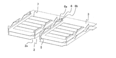
- FIG. 1 is a perspective view (main part enlarged view) showing a heat exchanger according to Embodiment 1 of the present invention.
- FIG. 2 is a perspective view (main part enlarged view) showing a laminated state of plate-like fins in the heat exchanger according to Embodiment 1 of the present invention.
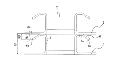
- FIG. 3 is a side view of the plate-like fin shown in FIG. 3 shows the plate-like fin 3 observed in the longitudinal direction of the notch 2 (in other words, the long axis direction of the heat transfer tube 1).
- the heat exchanger 4 is a fin-and-tube heat exchanger, which is stacked with a predetermined fin pitch interval FP, and a plurality of notches 2 are formed at the end in the longitudinal direction.
- the plurality of plate-like fins 3 and the plurality of flat heat transfer tubes 1 that are arranged in the stacking direction of the plate-like fins 3 and are inserted into the notch portions 2 are provided.
- the plate-like fins 3 and the heat transfer tubes 1 are made of, for example, aluminum (made of aluminum or aluminum alloy).
- the heat transfer tube 1 only needs to have at least one refrigerant flow path therein, and is configured as shown in FIGS. 4 and 5, for example.
- FIG. 4 is a cross-sectional view showing an example of the heat transfer tube according to Embodiment 1 of the present invention.
- the heat transfer tube 1 is formed in a flat shape having a substantially oval cross section, and one refrigerant channel is formed therein.
- FIG. 5 is a cross-sectional view showing another example of the heat transfer tube according to Embodiment 1 of the present invention.
- the heat transfer tube 1 may be formed in a flat shape having a substantially oval cross section, and a plurality of refrigerant flow paths may be formed inside the heat transfer tube 1 along the long axis direction of the heat transfer tube 1.
- the heat exchanger tube 1 is not limited to the structure of FIG.4 and FIG.5.
- the cross-sectional shape of the heat transfer tube 1 may be formed in a substantially elliptical shape.
- a groove may be formed on the wall surface of the refrigerant flow path of the heat transfer tube 1 (inner wall surface of the heat transfer tube 1). The contact area between the inner surface of the heat transfer tube and the refrigerant is increased, and the heat exchange efficiency is improved.
- the major axis diameter of the heat exchanger tube 1 is defined as DA
- the minor axis diameter is defined as DB.
- each plate-like fin 3 is formed with a plurality of notches 2 into which the heat transfer tubes 1 are inserted at the end on the longitudinal direction side.
- the shape of each notch part 2 is formed in the shape corresponding to the cross-sectional shape of the heat exchanger tube 1, as shown in FIG.1 and FIG.2.
- a guide portion 2 a having a width wider than the width of the cutout portion 2 is formed at the opening side end portion of the cutout portion 2.
- a fin collar 5 is formed on the periphery of each notch 2 so as to stand up from the periphery and adhere to the outer periphery of the heat transfer tube 1.
- Each fin collar 5 has at least one reflared portion 6 that is bent to the opposite side to the side surface on the long axis side of the heat transfer tube 1 in contact with the fin collar 5.
- the adjacent plate-like fins 3 have a flared portion 6 of one plate-like fin 3 (more specifically, a reflier base end portion 6 a), and a bottom surface portion 3 a of the other plate-like fin 3 ( By being in contact with the contact side surface), they are arranged via the fin pitch interval FP.
- the flared portion 6 includes both side surfaces on the long axis side of the heat transfer tube 1. It is provided at an opposing position.
- each reflare part 6 is formed with the reflare base end part 6a and the reflare front-end
- the reflaring base end portion 6a is a portion that contacts the bottom surface portion 3a of the adjacent plate-like fin 3 in order to maintain the fin pitch interval FP.
- the reflaring tip portion 6b is formed so as to be separated from the bottom surface portion 3a of the plate-like fin 3 with which the reflaring base end portion 6a contacts.
- a portion farthest in the stacking direction of the plate-like fins 3 from the bottom surface portion 3a of the plate-like fin 3 with which the flaring base end portion 6a is in contact is particularly defined as a terminal end portion 6c of the flaring tip portion.
- the angle ⁇ formed by the bottom surface portion 3a of the plate-like fin 3 that is in contact with the base portion 6a of the flares and the tip portion 6b of the flares is 0 ° ⁇ ⁇ 90 °.
- ⁇ the wind speed of the air passing through the flared tip portion 6b is increased, so that the leading edge effect can be obtained more efficiently.
- ⁇ > 90 ° the interval between the fin collar 5 and the refractor tip 6b is narrowed, and the condensed water of moisture in the air generated when the heat exchanger 4 is used as an evaporator bridges. This is because it becomes easier.
- each plate-like fin 3 according to the first embodiment has a scratch 7 formed on the fin surface.
- the scratch 7 heat transfer can be promoted in this portion compared to the planar shape, and the buckling strength of the plate-like fin 3 can be improved.
- the plate-like fins 3 may be formed with cuts and raises called slits. Heat transfer can also be promoted by forming slits in the plate-like fins 3.
- the shape of the reflare part 6 which concerns on this Embodiment 1 is not limited to said structure.
- an example of the shape of the reflare part 6 is shown.
- the flared portion 6 may be formed in a rectangular shape.
- the flared portion 6 may be formed in a triangular shape.
- the flared portion 6 may be formed in a sine wave shape.
- the flared portion 6 may be formed in a shape other than those shown in FIGS.
- the flaring portion 6 is provided at a position facing both side surfaces on the long axis side of the heat transfer tube 1, but the refringing portion 6 may be provided only at a position facing either one of the side surfaces. Good.
- the reflare tip 6b is formed on all the reflares 6, but the heat transfer area is increased in the region around the heat transfer tube 1 by forming the reflare tip 6b on at least one reflare 6. It is possible to ensure heat exchange efficiently by the leading edge effect.
- FIG. 10 is a plan view showing another example of the plate-like fin according to Embodiment 1 of the present invention.
- the long axis of the heat transfer tube 1 is located at a position facing one side surface of the long axis of the heat transfer tube 1.
- a maximum of two reflare parts 6 (reflare tip part 6b) were formed along the direction. This number does not stipulate the maximum number of the flared portions 6 provided at a position facing one side surface of the long axis side of the heat transfer tube 1.
- three or more (four in FIG. 10) flared portions 6 four in FIG.
- a flared tip 6b may be formed.
- reflare tip part 6b By increasing the number of the reflare parts 6 (reflare tip part 6b), it is possible to secure more reflare wind upper parts 6d that can obtain the leading edge effect, and thus particularly improve the heat exchange performance. It becomes possible.
- FIG. 11 is a side view showing still another example of the plate-like fin according to Embodiment 1 of the present invention.
- the distance (the distance in the stacking direction of the plate-like fins 3) between the bottom surface portion 3a of the plate-like fin 3 and the end portion 6c of the flared tip portion is a reflair pitch RP
- the flared pitch RP was shorter than half the fin pitch interval FP.
- the plate-like fins 3 may be formed so that the flared pitch RP is longer than half the fin pitch interval FP.
- the wind speed of the air passing through the flow path between the plate fins 3 becomes maximum at the center portion of the fin pitch interval FP away from the bottom surface portion 3 a of the plate fin 3. For this reason, by forming the plate-like fins 3 so that the reflare pitch RP is longer than half the fin pitch interval FP, it is possible to secure more reflared upper portions 6d that can obtain the leading edge effect. Therefore, the heat exchange performance can be particularly improved.
- the heat exchanger tube 1 which concerns on this Embodiment 1 may be a heat exchanger tube in which the some refrigerant
- the heat exchanger 4 By configuring the heat exchanger 4 with the heat transfer tubes 1 having such a plurality of refrigerant flow paths and the plate fins 3, the following effects can be obtained.
- the heat exchanger 104 that does not have the flared portion 6 (that is, the refracted tip portion 6b). explain. Thereafter, the heat exchanger 4 according to the first embodiment will be described.
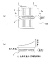
- FIG. 12 is a view showing a heat exchanger as a comparative example.
- Fig.12 (a) is a top view which shows the heat exchanger 104 used as a comparative example.
- FIG. 12B is a diagram showing the heat flux distribution of the heat exchanger 104. Note that air flows into the heat exchanger 104 from the direction indicated by the white arrow.
- a heat exchanger 104 as a comparative example includes a heat transfer tube 1 having a plurality of flow paths through which a refrigerant (or water) flows.
- the heat exchanger 104 has a configuration that does not include the flaring portion 6 (that is, the reflare tip portion 6b).
- air flows into the heat exchanger 104 from the right hand side of the sheet exchanges heat with the refrigerant and the plate-like fins 3 in the heat transfer tube 1, and flows out from the left hand side of the sheet.
- the heat exchanger 104 is used as an outdoor heat exchanger (evaporator) in an environment where the outside air temperature is about 2 ° C. or less and the refrigerant evaporation temperature is 0 ° C. or less and frost formation occurs in the heat exchanger 104.
- the windward end portion 3b of the plate fin 3 and the windward end portion 1c of the heat transfer tube 1 are arranged at positions where the leading edge effect is obtained and the heat exchange performance is improved, and the absolute humidity of the air is large. Therefore, intensive frosting occurs at the windward end portion 3b of the plate-like fin 3 and the windward end portion 1c of the heat transfer tube 1 so that frost formation is likely to occur at that location.
- the heat exchanger 104 the air path in the vicinity of the location is blocked by frost, and the air flow is reduced by increasing the ventilation resistance, so that the heat exchange performance is lowered.
- FIG.13 and FIG.14 is a figure which shows an example using the heat exchanger tube which has a some refrigerant
- (a) in FIG.13 and FIG.14 is a top view which shows the heat exchanger 4 which concerns on this Embodiment 1.
- FIG. Moreover, (b) in FIG.13 and FIG.14 is a figure which shows the heat flux distribution of the heat exchanger 4 shown to each drawing. Air flows into the heat exchanger 4 shown in FIGS. 13 and 14 from the direction indicated by the white arrow.
- 6e is a reflare tip portion closest to the windward side end portion 1c (first end portion) of the heat transfer tube 1 in the reflare tip portion 6b
- 6f is a leeward side end of the heat transfer tube 1 in the reflare tip portion 6b
- the flared tip portion closest to the portion 1b (second end portion) is shown.
- the heat exchanger 4 shown in FIG. 13 and the heat exchanger 4 shown in FIG. 14 are “the windward end portion 1c (first end portion) of the heat transfer tube 1 and the flared tip closest to the windward end portion 1c.
- the distance B "with the part 6e is different.
- the heat exchanger 4 includes a heat transfer tube 1 having a plurality of flow paths through which a refrigerant (or water) flows. Further, these heat exchangers 4 are formed with plate-like fins 3 shown in FIG. 10 (four flares 6 (reflare tips 6b) at positions facing both side surfaces on the long axis side of the heat transfer tube 1). Are provided). As described above, by increasing the number of the refracting tip portions 6b, it is possible to secure a larger number of the flared wind upper portions 6d that can obtain the leading edge effect. For this reason, generation
- the heat exchanger 4 according to the first embodiment can suppress variation in the temperature distribution of the refrigerant by the refrigerant flow path, the heat exchange performance as one heat transfer tube 1 (in other words, heat at the periphery of the heat transfer tube 1). Exchange performance) can be improved.
- the plate-like fin 3 shown in FIGS. 13 and 14 is provided with a plurality of flared tip portions 6b at positions facing both side surfaces of the heat transfer tube 1 on the long axis side. Compared with the case where a plurality of refractor tip portions 6b are provided only at a position facing one side surface, the number of reflier tip portions 6b can be increased, and the above-described effects can be further obtained.
- the heat exchanger 4 shown in FIG. 14 has a “distance B between the windward side end 1c (first end) of the heat transfer tube 1 and the flared tip 6e closest to the windward side end 1c”.
- the structure is longer than the distance “A” between the leeward side end portion 1b (second end portion) of the heat transfer tube 1 and the flared tip portion 6f closest to the leeward side end portion 1b. That is, the heat exchanger 4 shown in FIG. 14 has a configuration in which the flared tip 6e closest to the windward end 1c is separated from the windward end 1c.
- the heat exchanger 4 shown in FIG.13 and FIG.14 is improving the heat exchange performance of the heat exchanger tube 1 periphery, suppressing the shift
- Embodiment 2 the manufacturing method of the heat exchanger 4 shown in Embodiment 1, especially the manufacturing method of the plate-like fin 3 is demonstrated.
- the cost of the heat exchanger 4 can be reduced, and the production capacity (the number of sheets manufactured per unit time) of the plate-like fins 3 can be improved.
- configurations that are not particularly mentioned are the same as those in the first embodiment, and the same components as those in the first embodiment are denoted by the same reference numerals.
- the aluminum plate material 11 (aluminum plate material or aluminum alloy plate material) is used as an example of the raw material of the plate-like fin 3.
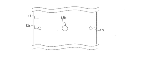
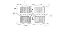
- FIG. 15 is an explanatory diagram for explaining the plate-like fin manufacturing method according to the second embodiment of the present invention, and is a plan view for explaining the pilot hole forming step.
- a plurality of pilot hole groups composed of at least two first pilot holes 12 a are formed at predetermined intervals with respect to the aluminum plate material 11 that is a raw material of the plate-like fins 3.
- Each first pilot hole 12 a forms the bottom of the notch 2.
- the guiding portion 2 a is formed at the opening end of the notch portion 2 of the plate-like fin 3.
- each pilot hole group a second pilot hole 12b having a diameter larger than that of the first pilot hole 12a is formed at a position between the first pilot holes 12a located at both ends.
- the waste material is only the portion cut out as the first pilot hole 12a and the second pilot hole 12b. It can be used, and the cost of the plate-like fins 3 (in other words, the heat exchanger 4) can be reduced.
- 16 to 19 are explanatory views for explaining the plate-like fin manufacturing method according to the second embodiment of the present invention, and are plan views for explaining the cut forming process.
- a cut is formed so as to connect the first pilot holes 12a in each pilot hole group.
- the shape of the cut is various, and varies depending on the shape of the flared portion 6.
- the cut line 13a is formed on a virtual straight line connecting the centers of the first pilot holes 12a located at both ends.
- the rectangular flared portions 6 are formed one by one at positions facing both side surfaces on the long axis side of the heat transfer tube 1.
- a cut is formed so as to intersect at least one virtual straight line connecting the centers of the first pilot holes 12a located at both ends.
- a plurality of refracting portions 6 are formed at a position facing at least one side surface of the heat transfer tube 1 on the long axis side.
- the shape of the refracted portion 6 becomes a triangular shape as shown in FIG.
- the shape of the refracting portion 6 becomes a sine wave shape as shown in FIG.
- a rectangular cut 13d as shown in FIG. 19 the shape of the refracting portion 6 becomes a rectangular shape as shown in FIG.
- the shape of the cut affects the shape of the flared portion 6 shown in the first embodiment. Details of the influence will be described in the fin collar 5 forming step (rising portion forming step), which is a subsequent step.
- FIG. 20 is an explanatory diagram for explaining the plate-like fin manufacturing method according to the second embodiment of the present invention, and is a plan view for explaining the pressing step.
- the aluminum plate 11 is pressed to form the scratch 7.
- the scratch 7 is intended to promote heat transfer in this portion and improve the buckling strength of the plate-like fin 3. Note that this step is not necessary when the scratch 7 is not formed.
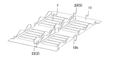
- 21 and 22 are explanatory diagrams for explaining the plate-like fin manufacturing method according to the second embodiment of the present invention, and are explanatory diagrams for explaining the rising portion forming step.
- 21 is a side view
- FIG. 22 is a perspective view.
- FIG. 22 shows a state after burring the zigzag cut 13b shown in FIG.
- the cut formed in the cut forming process is subjected to burring to form the rising portion 25 to be the fin collar 5 and the opening 22 to be the notched portion 2.
- burring is performed so that the width of the opening 22 (that is, the notch 2) is the same length as the heat transfer tube short axis diameter DB.
- the maximum height FCmax of the rising portion 25 varies depending on the shape of the cut formed in the cut forming step. .
- the ridge line of the rising portion 25 is also the same. It has a zigzag shape. That is, depending on the zigzag angle and the pitch of the zigzag top, the height FC of the rising portion 25 varies along the imaginary straight line (the longitudinal direction of the cutout portion 2 and the long axis direction of the heat transfer tube 1). ing. For this reason, the range of the maximum height FCmax of the rising portion 25 is DB / 2 ⁇ FCmax ⁇ DB.
- a refringing part forming process for forming the refringing part 6 is performed. That is, the front end portion of the rising portion 25 is bent to the side opposite to the side surface on the long axis side of the heat transfer tube 1 to form the flared portion 6.
- the role of the reflare section 6 in the present invention is as follows. ⁇ Ensure fin pitch interval FP, -Heat transfer enhancement by the reflare tip 6b, There are two points. For this reason, the maximum height FCmax of the rising portion 25 is preferably as long as possible. This is because it is possible to increase the refreer pitch RP while ensuring a sufficient fin pitch interval FP, and thus heat transfer can be promoted.
- a plurality of flared portions 6 can be formed on one side surface of the heat transfer tube 1 by forming a cut so as to intersect at least one virtual straight line connecting the centers of the first pilot holes 12a located at both ends. It becomes possible.
- the number of the reflare parts 6 increases, so that there are many frequency
- the maximum height FCmax of the rising portion 25 needs to be at least longer than the fin pitch interval FP in order to form the flared portion 6. That is, a length of FCmax> FP is required. Moreover, the maximum height of the rising part 25 is extended by carrying out the process of narrowing the rising part 25 called ironing, or by collecting the thick part of the aluminum plate 11 called drawing and extending the rising part 25. It becomes possible to do.
- the pitch interval FP It becomes longer than the half length of the pitch interval FP, that is, RP> FP / 2, and in particular, the heat exchange performance can be improved. For this reason, it is preferable to form the rising portion 25 so that the maximum height FCmax of the rising portion 25 satisfies 1.0 ⁇ (FCmax / FP) ⁇ 2.0.
- FIG. 23 is an explanatory diagram for explaining the plate-like fin manufacturing method according to the second embodiment of the present invention, and is a plan view for explaining the cutting step.
- the aluminum plate material 11 is cut
- by cutting the aluminum plate material 11 at the fin cutting surface 14 (more specifically, cutting the position at the end of the plate-like fin 3 together with the cutting at the fin cutting surface 14 or thereafter.
- two plate-like fins 3 can be manufactured at a time with the fin cut surface 14 as a boundary. For this reason, the manufacturing capability of the plate-like fin 3 can be improved by manufacturing the plate-like fin 3 as in the second embodiment.
- Embodiment 2 As a manufacturing process of the heat exchanger 4, predetermined
- FIG. A stacking process called stacking is carried out until it becomes. Further, after the stacking, the heat transfer tube 1 is inserted into the notch 2 and brazed in the furnace so that the heat transfer tube 1 and the plate-like fins 3 are brought into close contact with each other to manufacture the heat exchanger 4.
- 1 heat transfer tube 1b leeward side edge, 1c windward edge, 2 notch, 2a lead-in part, 3 plate fin, 3a bottom surface, 3b windward edge, 4 heat exchanger, 5 fin collar, 6 reflair Part, 6a reflare base end, 6b reflare tip, 6c end of reflare tip, 6d reflare wind top, 6e reflare tip, 6f reflare tip, 7 scratch, 11 aluminum plate, 12a first pilot hole, 12b Second pilot hole, 13a to 13d cut, 14 fin cut surface, 22 opening, 25 rising part, 104 heat exchanger.
Abstract
Description
以下、本発明の実施の形態1に係る熱交換器4、及び、該熱交換器4に用いられる板状フィン3について、図1~図14に基づいて説明する。
なお、本実施の形態1では、本実施の形態1に係る板状フィン3の構成の理解を容易にするため、要部拡大図(板状フィン3の枚数を2枚、伝熱管1の本数を1本に絞った熱交換器4の一部を図示したもの)を基に、本発明の実施の形態1に係る熱交換器4及び板状フィン3を説明する。
例えば、伝熱管1は、略長円形状の断面を有する扁平形状に形成され、その内部に1本の冷媒流路が形成される。
図5は、本発明の実施の形態1に係る伝熱管の別の一例を示す断面図である。
例えば、伝熱管1は、略長円形状の断面を有する扁平形状に形成され、その内部に、伝熱管1の長軸方向に沿って複数の冷媒流路が形成されてもよい。内部に複数の冷媒流路を形成することにより、伝熱管内面と冷媒との接触面積が増え、熱交換効率が良くなる。
また、伝熱管1は、図4及び図5の構成に限定されるものではない。例えば、伝熱管1の断面形状を略楕円形状に形成してもよい。また例えば、伝熱管1の冷媒流路の壁面(伝熱管1の内壁面)に溝を形成してもよい。伝熱管内面と冷媒との接触面積が増え、熱交換効率が良くなる。
なお、図5に示すように、伝熱管1の長軸径をDA、短軸径をDBとそれぞれ定義する。
上述のように、各板状フィン3は、長手方向側の端部に、伝熱管1が挿入される複数の切欠部2が形成される。このため、各切欠部2の形状は、図1及び図2に示すように、伝熱管1の断面形状に対応する形に形成されている。また、本実施の形態1では、伝熱管1の切欠部2への挿入を容易にするため、切欠部2の開口側端部に、切欠部2の幅よりも広い幅の誘い込み部2aが形成されている。
なお、リフレア先端部6bにおいて、リフレア基端部6aが接する板状フィン3の底面部3aから板状フィン3の積層方向に最も離れた部位を、特にリフレア先端部の終端部6cと定義する。
つまり、本実施の形態1のようにリフレア部6を構成することにより、伝熱促進が困難な伝熱管1周縁の領域において伝熱面積を確保し、さらに前縁効果により、効率良く熱交換することが可能となる。
例えば、図6及び図8に示すように、リフレア部6を矩形状に形成してもよい。例えば、図7に示すように、リフレア部6を三角形状に形成してもよい。また例えば、図9に示すように、リフレア部6を正弦波形状に形成してもよい。また例えば、リフレア部6を、これら図6~図9に示した以外の形状に形成しても勿論よい。また、図6~図9では、伝熱管1の長軸側の両側面と対向する位置にリフレア部6を設けたが、どちらか一方の側面と対向する位置のみにリフレア部6を設けてもよい。また、上記の説明では、リフレア部6の全てにリフレア先端部6bを形成したが、少なくとも1つのリフレア部6にリフレア先端部6bを形成することにより、伝熱管1周縁の領域において伝熱面積を確保でき、前縁効果によって効率良く熱交換することが可能となる。
上述した図1~図9では、同一の切欠部2の周縁に設けられたフィンカラー5に着目すると、伝熱管1の長軸側の一側面と対向する位置には、伝熱管1の長軸方向に沿って最大2つのリフレア部6(リフレア先端部6b)が形成されていた。この数は、伝熱管1の長軸側の一側面と対向する位置に設けられるリフレア部6の最大数を規定するものではない。例えば、図10に示すように、伝熱管1の長軸側の一側面と対向する位置に、伝熱管1の長軸方向に沿って3つ以上(図10では4つ)のリフレア部6(リフレア先端部6b)を形成してもよい。このようにリフレア部6(リフレア先端部6b)の個数をより多くすることで、前縁効果を得ることができるリフレア風上部6dをより多く確保することができるため、特に熱交換性能を向上させることが可能となる。
板状フィン3の底面部3aとリフレア先端部の終端部6cとの間の距離(板状フィン3の積層方向の距離)をリフレアピッチRPとすると、図3に示した板状フィン3は、リフレアピッチRPがフィンピッチ間隔FPの半分の長さよりも短くなっていた。これに限らず、図11に示すように、リフレアピッチRPがフィンピッチ間隔FPの半分の長さよりも長くなるように、板状フィン3を形成してもよい。板状フィン3間の流路を通る空気の風速は、板状フィン3の底面部3aから離れたフィンピッチ間隔FPの中央部において最大となる。このため、リフレアピッチRPがフィンピッチ間隔FPの半分の長さよりも長くなるように、板状フィン3を形成することにより、前縁効果を得ることができるリフレア風上部6dをより多く確保することができるため、特に熱交換性能を向上させることが可能となる。
ここで、以下では、本実施の形態1に係る熱交換器4の効果の理解を容易とするため、まず、リフレア部6(つまり、リフレア先端部6b)を有していない熱交換器104について説明する。その後、本実施の形態1に係る熱交換器4について説明する。なお、リフレア部6(つまり、リフレア先端部6b)を有していない熱交換器104と本実施の形態1に係る熱交換器4とで共通する構成については、同じ符号を付すものとする。
なお、図13に示す熱交換器4と図14に示す熱交換器4とは、「伝熱管1の風上側端部1c(第一端部)と該風上側端部1cに最も近いリフレア先端部6eとの距離B」が異なっている。
本実施の形態2では、実施の形態1で示した熱交換器4の製造方法、特に板状フィン3の製造方法について説明する。本実施の形態2のように板状フィン3を製造することにより、熱交換器4のコストを削減でき、板状フィン3の製造能力(単位時間当たりの製造枚数)を向上させることができる。
なお、本実施の形態2において、特に言及しない構成については実施の形態1と同様とし、実施の形態1と同じ構成については同じ符号を付すものとする。また、本実施の形態2では、板状フィン3の原材料の一例として、アルミ板材11(アルミニウム板材又はアルミニウム合金板材)を用いている。
板状フィン3を製造する際、まず、板状フィン3の原材料となるアルミ板材11に対して、少なくとも2つの第一下穴12aで構成された下穴グループを所定の間隔を介して複数形成する。各第一下穴12aは、切欠部2の底部を形成するものである。なお、本実施の形態2では、板状フィン3の切欠部2の開口端に、誘い込み部2aを形成する。このため、各下穴グループにおいて、両端に位置する第一下穴12aの間の位置に、該第一下穴12aよりも直径が大きい第二下穴12bを形成している。
ここで、本実施の形態2に示す板状フィン3の製造方法においては、廃材となるのは第一下穴12a及び第二下穴12bとしてくり抜いた当部のみであるため、効率良く材料を使用することができ、板状フィン3(換言すると熱交換器4)のコストを削減させることができる。
下穴形成工程の後、各下穴グループにおいて、第一下穴12aを繋ぐように切れ目を形成する。切れ目の形状は様々であり、リフレア部6の形状により異なってくる。例えば、図16に示すように、同一の下穴グループにおいて、両端に位置する第一下穴12aの中心を結ぶ仮想直線上に切れ目13aを形成する。この場合、図6で示したように、伝熱管1の長軸側の両側面と対向する位置に1つずつ、矩形状のリフレア部6が形成されることとなる。
切れ目形成工程の後、アルミ板材11をプレス加工して、スクラッチ7を形成する。前述の通り、このスクラッチ7は当部における伝熱促進と、板状フィン3の座屈強度の向上を目的としている。なお、スクラッチ7を形成しない場合には、この工程は不要となる。
・フィンピッチ間隔FPの確保、
・リフレア先端部6bによる伝熱促進、
の二点が挙げられる。そのため、立ち上がり部25の最大高さFCmaxは、なるべく長い方が好ましい。十分なフィンピッチ間隔FPを確保しつつ、リフレアピッチRPを長くすることができるので、伝熱促進が可能となるからである。また、両端に位置する第一下穴12aの中心を結ぶ仮想直線を少なくとも一カ所以上交差するように切れ目を形成することで、伝熱管1の一側面にリフレア部6を複数個形成することが可能となる。そして、リフレア部6の個数は交差する回数が多いほど増加する。
すなわち、本発明におけるリフレア部6の役割を十分に発揮するためには、両端に位置する第一下穴12aの中心を結ぶ仮想直線を複数回交差するように切れ目を形成する方が、より効果的である。
このため、立ち上がり部25の最大高さFCmaxが1.0<(FCmax/FP)≦2.0となるように、立ち上がり部25を形成することが好ましい。
リフレア部形成工程の後、フィン切断面14でアルミ板材11を切断する。つまり、下穴グループの配列方向に沿って、開口部22を横断するようにアルミ板材11を切断する。これにより、立ち上がり部25がフィンカラー5となり、開口部22が切欠部2となる。図23からわかるように、フィン切断面14でアルミ板材11を切断することにより(より詳しくは、フィン切断面14での切断と共に、あるいはその後に板状フィン3の端部となる位置も切断することにより)、フィン切断面14を境にして、一度に2枚分の板状フィン3を製造することができる。このため、本実施の形態2のように板状フィン3を製造することにより、板状フィン3の製造能力を向上させることができる。
Claims (13)
- フィンピッチ間隔を介して積層され、長手方向に配列された複数の切欠部が形成された複数の板状フィンと、
前記板状フィンの積層方向に沿って配置され、前記切欠部に挿入された複数の扁平形状の伝熱管と、
を備え、
前記板状フィンは、前記切欠部の周縁に、前記伝熱管の外周部と密着するフィンカラーを有し、
前記フィンカラーは、少なくとも1つのリフレア部を有し、
隣り合う前記板状フィン同士は、一方の前記板状フィンの前記リフレア部が他方の前記板状フィンと接して、前記フィンピッチ間隔で配置されており、
前記リフレア部の少なくとも1つは、隣接する前記板状フィンから離れているリフレア先端部を有する熱交換器。 - 前記伝熱管の長軸方向に前記リフレア先端部を有する前記リフレア部を観察した状態においては、
前記リフレア先端部と、該リフレア先端部を有する前記リフレア部と接する前記板状フィンの接触側面とのなす角度θが、0°<θ<90°となっている請求項1に記載の熱交換器。 - 前記リフレア先端部の終端部と、該リフレア先端部を有する前記リフレア部と接する前記板状フィンの接触側面との間の距離が、前記フィンピッチ間隔の半分の長さよりも長い請求項1又は請求項2に記載の熱交換器。
- 前記伝熱管は、その内部に、該伝熱管の長軸方向に沿って複数の流路が形成されたものであり、
前記リフレア先端部を有する前記リフレア部が、同一の前記切欠部の周縁に設けられた前記フィンカラーにおいて、前記伝熱管の長軸方向に沿って複数形成されている請求項1~請求項3のいずれか一項に記載の熱交換器。 - 前記リフレア先端部を有する前記リフレア部は、同一の前記切欠部の周縁に設けられた前記フィンカラーにおいて、該フィンカラーと接する前記伝熱管の長軸側の両側面と対向する位置に形成され、
複数の前記リフレア先端部が、該フィンカラーと接する前記伝熱管の長軸側の両側面に交互に設けられている請求項4に記載の熱交換器。 - 前記伝熱管の風上側の端部である第一端部と該第一端部に最も近い前記リフレア先端部との距離が、前記伝熱管の風下側の端部である第二端部と該第二端部に最も近い前記リフレア先端部との距離よりも長い請求項4又は請求項5に記載の熱交換器。
- 前記切欠部の開口側端部に、前記切欠部の幅よりも広い幅の誘い込み部が形成されている請求項1~請求項6のいずれか一項に記載の熱交換器。
- 複数の前記板状フィンに、スクラッチ及びスリットのうちの少なくとも一方が形成されている請求項1~請求項7のいずれか一項に記載の熱交換器。
- 請求項1~請求項8のいずれか一項に記載の熱交換器の前記板状フィンの製造方法であって、
板状部材に対して、少なくとも2つの第一下穴で構成された下穴グループを間隔を介して複数形成する下穴形成工程と、
該下穴形成工程の後、各下穴グループにおいて、前記第一下穴を繋ぐように切れ目を形成する切れ目形成工程と、
該切れ目形成工程の後、前記切れ目をバーリング加工し、前記フィンカラーとなる立ち上がり部及び前記切欠部となる開口部を形成する立ち上がり部形成工程と、
該立ち上がり部形成工程の後、前記立ち上がり部をリフレア加工し、前記リフレア部を形成するリフレア部形成工程と、
前記リフレア部形成工程の後、前記下穴グループの配列方向に沿って前記板状部材を切断し、前記フィンカラー及び前記切欠部を形成する切断工程と、
を備えた熱交換器の板状フィンの製造方法。 - 前記切れ目形成工程で形成される切れ目は、同一の下穴グループにおいて両端に位置する第一下穴の中心を結ぶ仮想直線を、少なくとも一カ所以上交差するように形成される請求項9に記載の熱交換器の板状フィンの製造方法。
- 前記立ち上がり部形成工程と前記リフレア部形成工程との間に、
前記フィンピッチ間隔をFPと定義した場合、前記立ち上がり部の最大高さFCmaxが1.0<(FCmax/FP)≦2.0となるように、前記立ち上がり部にアイアリング加工又はドローイング加工を施す工程を備えた請求項9又は請求項10に記載の熱交換器の板状フィンの製造方法。 - 請求項7に記載の熱交換器の前記板状フィンの製造方法であり、
前記下穴形成工程で複数の前記下穴グループを形成する際、同一の下穴グループにおいて両端に位置する第一下穴の間の位置に、該第一下穴よりも直径が大きく、前記誘い込み部となる第二下穴を形成する請求項9~請求項11のいずれか一項に記載の熱交換器の板状フィンの製造方法。 - 請求項8に記載の熱交換器の前記板状フィンの製造方法であり、
前記板状部材をプレス加工して、前記スクラッチ及び前記スリットのうちの少なくとも一方を形成するプレス工程を備えた請求項9~請求項12のいずれか一項に記載の熱交換器の板状フィンの製造方法。
Priority Applications (11)
| Application Number | Priority Date | Filing Date | Title |
|---|---|---|---|
| KR1020197032001A KR20190124820A (ko) | 2014-09-08 | 2014-09-08 | 열교환기 |
| KR1020177004999A KR102089099B1 (ko) | 2014-09-08 | 2014-09-08 | 열교환기 |
| JP2016547263A JP6294497B2 (ja) | 2014-09-08 | 2014-09-08 | 熱交換器 |
| US15/504,467 US10041739B2 (en) | 2014-09-08 | 2014-09-08 | Heat exchanger and method for manufacturing plate-shaped fins for heat exchanger |
| PCT/JP2014/073609 WO2016038652A1 (ja) | 2014-09-08 | 2014-09-08 | 熱交換器及び熱交換器の板状フィンの製造方法 |
| AU2014405791A AU2014405791B2 (en) | 2014-09-08 | 2014-09-08 | Heat exchanger and method for manufacturing plate-shaped fins for heat exchanger |
| CN201480081645.0A CN106716042B (zh) | 2014-09-08 | 2014-09-08 | 热交换器以及热交换器的板状翅片的制造方法 |
| EP14901620.6A EP3193121B1 (en) | 2014-09-08 | 2014-09-08 | Heat exchanger |
| KR1020187037603A KR20190000926A (ko) | 2014-09-08 | 2014-09-08 | 열교환기 |
| US16/026,528 US10563924B2 (en) | 2014-09-08 | 2018-07-03 | Heat exchanger and method for manufacturing plate-shaped fins for heat exchanger |
| AU2018278876A AU2018278876B2 (en) | 2014-09-08 | 2018-12-11 | Heat exchanger and method for manufacturing plate-shaped fins for heat exchanger |
Applications Claiming Priority (1)
| Application Number | Priority Date | Filing Date | Title |
|---|---|---|---|
| PCT/JP2014/073609 WO2016038652A1 (ja) | 2014-09-08 | 2014-09-08 | 熱交換器及び熱交換器の板状フィンの製造方法 |
Related Child Applications (2)
| Application Number | Title | Priority Date | Filing Date |
|---|---|---|---|
| US15/504,467 A-371-Of-International US10041739B2 (en) | 2014-09-08 | 2014-09-08 | Heat exchanger and method for manufacturing plate-shaped fins for heat exchanger |
| US16/026,528 Continuation US10563924B2 (en) | 2014-09-08 | 2018-07-03 | Heat exchanger and method for manufacturing plate-shaped fins for heat exchanger |
Publications (1)
| Publication Number | Publication Date |
|---|---|
| WO2016038652A1 true WO2016038652A1 (ja) | 2016-03-17 |
Family
ID=55458445
Family Applications (1)
| Application Number | Title | Priority Date | Filing Date |
|---|---|---|---|
| PCT/JP2014/073609 WO2016038652A1 (ja) | 2014-09-08 | 2014-09-08 | 熱交換器及び熱交換器の板状フィンの製造方法 |
Country Status (7)
| Country | Link |
|---|---|
| US (2) | US10041739B2 (ja) |
| EP (1) | EP3193121B1 (ja) |
| JP (1) | JP6294497B2 (ja) |
| KR (3) | KR20190124820A (ja) |
| CN (1) | CN106716042B (ja) |
| AU (2) | AU2014405791B2 (ja) |
| WO (1) | WO2016038652A1 (ja) |
Cited By (5)
| Publication number | Priority date | Publication date | Assignee | Title |
|---|---|---|---|---|
| WO2017183361A1 (ja) * | 2016-04-20 | 2017-10-26 | ダイキン工業株式会社 | 熱交換器 |
| JP2018048781A (ja) * | 2016-09-23 | 2018-03-29 | ダイキン工業株式会社 | 熱交換器 |
| JP2019089084A (ja) * | 2017-11-13 | 2019-06-13 | 三菱電機株式会社 | 管挿入装置及び管挿入方法 |
| JP2019196847A (ja) * | 2018-05-07 | 2019-11-14 | 三菱電機株式会社 | 熱交換器及び冷熱サイクル装置 |
| WO2020196592A1 (ja) * | 2019-03-28 | 2020-10-01 | 株式会社富士通ゼネラル | 熱交換器 |
Families Citing this family (8)
| Publication number | Priority date | Publication date | Assignee | Title |
|---|---|---|---|---|
| EP3321624B1 (en) * | 2015-07-10 | 2021-04-14 | Mitsubishi Electric Corporation | HEAT EXCHANGERS AND AIR-CONDITIONING DEVICE |
| JP6559334B2 (ja) * | 2016-04-15 | 2019-08-14 | 三菱電機株式会社 | 熱交換器 |
| WO2019062493A1 (zh) * | 2017-09-30 | 2019-04-04 | 杭州三花微通道换热器有限公司 | 换热器和翅片 |
| CN108844394A (zh) * | 2018-05-15 | 2018-11-20 | 杭州三花家电热管理系统有限公司 | 翅片、换热器、换热器的制作方法和换热系统 |
| CN112236640B (zh) * | 2018-06-13 | 2022-05-10 | 三菱电机株式会社 | 热交换器、热交换器单元及制冷循环装置 |
| CN110094993A (zh) * | 2019-05-10 | 2019-08-06 | 宁波德业科技股份有限公司 | 小口径热交换器 |
| US11835306B2 (en) * | 2021-03-03 | 2023-12-05 | Rheem Manufacturing Company | Finned tube heat exchangers and methods for manufacturing same |
| CN116197305B (zh) * | 2023-05-05 | 2023-07-07 | 德阳华智精密科技有限公司 | 一种板材折弯装置及杆体成型方法 |
Citations (12)
| Publication number | Priority date | Publication date | Assignee | Title |
|---|---|---|---|---|
| FR1539121A (fr) * | 1967-08-01 | 1968-09-13 | Chausson Usines Sa | Ailette à collet bas et outillage pour sa fabrication |
| JPS5680476U (ja) * | 1979-11-21 | 1981-06-30 | ||
| JPH03184645A (ja) * | 1989-12-11 | 1991-08-12 | Hidaka Seiki Kk | 熱交換器用フィン及びその製造法 |
| JP2001221587A (ja) * | 2000-02-10 | 2001-08-17 | Mitsubishi Electric Corp | フィンチューブ型熱交換器およびそれを用いた冷凍空調装置 |
| WO2002090856A1 (en) * | 2001-05-04 | 2002-11-14 | Calsonic Kansei Uk Limited | Heat exchanger system |
| JP2003329385A (ja) * | 2002-05-07 | 2003-11-19 | Mitsubishi Electric Corp | 熱交換器フィンおよび熱交換器フィン形成金型 |
| JP2004205124A (ja) * | 2002-12-25 | 2004-07-22 | Toyo Radiator Co Ltd | 熱交換器用プレートフィンおよび熱交換器コア |
| US20090044408A1 (en) * | 2005-03-29 | 2009-02-19 | John Lamkin | Fin-Tube Heat Exchanger Collar, and Method of Making Same |
| JP2010284688A (ja) * | 2009-06-11 | 2010-12-24 | Ken Kk | リフレア加工装置、リフレア加工用金型及びリフレア加工方法 |
| JP2011145023A (ja) * | 2010-01-15 | 2011-07-28 | Mitsubishi Electric Corp | 熱交換器およびその製造方法 |
| DE102012002234A1 (de) * | 2012-02-04 | 2013-08-08 | Volkswagen Aktiengesellschaft | Wärmetauscher mit mehreren Lamellen und Verfahren zur Herstellung einer Lamelle für einen Wärmetauscher |
| JP2014094389A (ja) * | 2012-11-08 | 2014-05-22 | Hidaka Seiki Kk | 熱交換器用フィンの製造装置 |
Family Cites Families (33)
| Publication number | Priority date | Publication date | Assignee | Title |
|---|---|---|---|---|
| JPS5624869Y2 (ja) | 1976-07-21 | 1981-06-11 | ||
| JPS5534139U (ja) | 1978-08-23 | 1980-03-05 | ||
| JPH02115675U (ja) * | 1989-02-28 | 1990-09-17 | ||
| US5360060A (en) * | 1992-12-08 | 1994-11-01 | Hitachi, Ltd. | Fin-tube type heat exchanger |
| JP3312986B2 (ja) * | 1994-02-25 | 2002-08-12 | 東芝キヤリア株式会社 | 熱交換器および熱交換器の製造方法 |
| JPH0829016A (ja) | 1994-07-19 | 1996-02-02 | Nippondenso Co Ltd | ヒートポンプ用室外熱交換器 |
| US5582246A (en) | 1995-02-17 | 1996-12-10 | Heat Pipe Technology, Inc. | Finned tube heat exchanger with secondary star fins and method for its production |
| JPH09324995A (ja) * | 1996-06-05 | 1997-12-16 | Toshiba Corp | 熱交換器 |
| JPH1078296A (ja) | 1996-09-03 | 1998-03-24 | Nippon Light Metal Co Ltd | 熱交換器 |
| JP3864916B2 (ja) * | 2002-08-29 | 2007-01-10 | 株式会社デンソー | 熱交換器 |
| DE102004012796A1 (de) * | 2003-03-19 | 2004-11-11 | Denso Corp., Kariya | Wärmetauscher und Wärmeübertragungselement mit symmetrischen Winkelabschnitten |
| JP2004340435A (ja) * | 2003-05-14 | 2004-12-02 | Mitsubishi Electric Corp | フィンチューブ型熱交換器およびその製造方法 |
| JP2005121288A (ja) | 2003-10-16 | 2005-05-12 | Matsushita Electric Ind Co Ltd | 熱交換器 |
| JP4275560B2 (ja) * | 2004-03-22 | 2009-06-10 | 三菱アルミニウム株式会社 | 耐アベック性、スタック性に優れた熱交換器用アルミニウム合金フィン材 |
| US20060218791A1 (en) * | 2005-03-29 | 2006-10-05 | John Lamkin | Fin-tube heat exchanger collar, and method of making same |
| JP2009281693A (ja) | 2008-05-26 | 2009-12-03 | Mitsubishi Electric Corp | 熱交換器、その製造方法及びこの熱交換器を用いた空調冷凍装置 |
| JP5304024B2 (ja) * | 2008-05-27 | 2013-10-02 | ダイキン工業株式会社 | フィンチューブ型熱交換器 |
| JP4845943B2 (ja) | 2008-08-26 | 2011-12-28 | 三菱電機株式会社 | フィンチューブ型熱交換器および冷凍サイクル空調装置 |
| US20100051247A1 (en) * | 2008-09-02 | 2010-03-04 | Calsonic Kansei Corporation | Heat exchanger made of aluminum alloy and method of producing same |
| JP5499957B2 (ja) * | 2009-07-24 | 2014-05-21 | 株式会社デンソー | 熱交換器 |
| JP5140051B2 (ja) | 2009-09-17 | 2013-02-06 | 三菱電機株式会社 | 熱交換器および熱交換器用フィンとその製造方法 |
| KR101451055B1 (ko) * | 2011-01-21 | 2014-10-16 | 다이킨 고교 가부시키가이샤 | 열교환기 및 공기 조화기 |
| CN103403486B (zh) | 2011-03-01 | 2015-12-09 | 三菱电机株式会社 | 热交换器以及具备该热交换器的冰箱、空气调节器 |
| JP5988177B2 (ja) * | 2011-11-25 | 2016-09-07 | パナソニックIpマネジメント株式会社 | フィンチューブ型熱交換器 |
| WO2013076990A1 (ja) * | 2011-11-25 | 2013-05-30 | パナソニック株式会社 | 伝熱フィン、フィンチューブ型熱交換器及びヒートポンプ装置 |
| EP2869016B1 (en) * | 2012-04-26 | 2017-11-15 | Mitsubishi Electric Corporation | Heat exchanger, method for manufacturing heat exchanger, and air conditioner |
| WO2013160959A1 (ja) * | 2012-04-27 | 2013-10-31 | 三菱電機株式会社 | 熱交換器、その製造方法及び冷凍サイクル装置 |
| KR101826365B1 (ko) * | 2012-05-04 | 2018-03-22 | 엘지전자 주식회사 | 열교환기 |
| JP2014048021A (ja) * | 2012-09-04 | 2014-03-17 | Panasonic Corp | フィンチューブ熱交換器およびそれを備えたヒートポンプ装置 |
| EP2725311B1 (en) | 2012-10-29 | 2018-05-09 | Samsung Electronics Co., Ltd. | Heat exchanger |
| JP2014089018A (ja) | 2012-10-31 | 2014-05-15 | Panasonic Corp | フィンチューブ熱交換器及びそれを備えた冷凍サイクル装置 |
| CN103245244B (zh) * | 2013-05-10 | 2016-03-16 | 丹佛斯微通道换热器(嘉兴)有限公司 | 换热器 |
| CN103697632B (zh) | 2013-12-10 | 2016-08-17 | 无锡微研有限公司 | 平行流翅片定片距折弯部的折弯机构 |
-
2014
- 2014-09-08 KR KR1020197032001A patent/KR20190124820A/ko not_active Application Discontinuation
- 2014-09-08 JP JP2016547263A patent/JP6294497B2/ja active Active
- 2014-09-08 US US15/504,467 patent/US10041739B2/en active Active
- 2014-09-08 EP EP14901620.6A patent/EP3193121B1/en active Active
- 2014-09-08 AU AU2014405791A patent/AU2014405791B2/en active Active
- 2014-09-08 KR KR1020177004999A patent/KR102089099B1/ko active IP Right Grant
- 2014-09-08 WO PCT/JP2014/073609 patent/WO2016038652A1/ja active Application Filing
- 2014-09-08 CN CN201480081645.0A patent/CN106716042B/zh active Active
- 2014-09-08 KR KR1020187037603A patent/KR20190000926A/ko active Application Filing
-
2018
- 2018-07-03 US US16/026,528 patent/US10563924B2/en active Active
- 2018-12-11 AU AU2018278876A patent/AU2018278876B2/en active Active
Patent Citations (12)
| Publication number | Priority date | Publication date | Assignee | Title |
|---|---|---|---|---|
| FR1539121A (fr) * | 1967-08-01 | 1968-09-13 | Chausson Usines Sa | Ailette à collet bas et outillage pour sa fabrication |
| JPS5680476U (ja) * | 1979-11-21 | 1981-06-30 | ||
| JPH03184645A (ja) * | 1989-12-11 | 1991-08-12 | Hidaka Seiki Kk | 熱交換器用フィン及びその製造法 |
| JP2001221587A (ja) * | 2000-02-10 | 2001-08-17 | Mitsubishi Electric Corp | フィンチューブ型熱交換器およびそれを用いた冷凍空調装置 |
| WO2002090856A1 (en) * | 2001-05-04 | 2002-11-14 | Calsonic Kansei Uk Limited | Heat exchanger system |
| JP2003329385A (ja) * | 2002-05-07 | 2003-11-19 | Mitsubishi Electric Corp | 熱交換器フィンおよび熱交換器フィン形成金型 |
| JP2004205124A (ja) * | 2002-12-25 | 2004-07-22 | Toyo Radiator Co Ltd | 熱交換器用プレートフィンおよび熱交換器コア |
| US20090044408A1 (en) * | 2005-03-29 | 2009-02-19 | John Lamkin | Fin-Tube Heat Exchanger Collar, and Method of Making Same |
| JP2010284688A (ja) * | 2009-06-11 | 2010-12-24 | Ken Kk | リフレア加工装置、リフレア加工用金型及びリフレア加工方法 |
| JP2011145023A (ja) * | 2010-01-15 | 2011-07-28 | Mitsubishi Electric Corp | 熱交換器およびその製造方法 |
| DE102012002234A1 (de) * | 2012-02-04 | 2013-08-08 | Volkswagen Aktiengesellschaft | Wärmetauscher mit mehreren Lamellen und Verfahren zur Herstellung einer Lamelle für einen Wärmetauscher |
| JP2014094389A (ja) * | 2012-11-08 | 2014-05-22 | Hidaka Seiki Kk | 熱交換器用フィンの製造装置 |
Non-Patent Citations (1)
| Title |
|---|
| See also references of EP3193121A4 * |
Cited By (17)
| Publication number | Priority date | Publication date | Assignee | Title |
|---|---|---|---|---|
| US10443956B2 (en) | 2016-04-20 | 2019-10-15 | Daikin Industries, Ltd. | Heat exchanger |
| CN109073333B (zh) * | 2016-04-20 | 2019-05-07 | 大金工业株式会社 | 热交换器 |
| WO2017183361A1 (ja) * | 2016-04-20 | 2017-10-26 | ダイキン工業株式会社 | 熱交換器 |
| CN109073333A (zh) * | 2016-04-20 | 2018-12-21 | 大金工业株式会社 | 热交换器 |
| EP3447430A4 (en) * | 2016-04-20 | 2020-01-15 | Daikin Industries, Ltd. | HEAT EXCHANGER |
| JP2017198440A (ja) * | 2016-04-20 | 2017-11-02 | ダイキン工業株式会社 | 熱交換器及び空調機 |
| CN109716053A (zh) * | 2016-09-23 | 2019-05-03 | 大金工业株式会社 | 热交换器 |
| JP2018048781A (ja) * | 2016-09-23 | 2018-03-29 | ダイキン工業株式会社 | 熱交換器 |
| WO2018056209A1 (ja) * | 2016-09-23 | 2018-03-29 | ダイキン工業株式会社 | 熱交換器 |
| US10619930B2 (en) | 2016-09-23 | 2020-04-14 | Daikin Industries, Ltd. | Heat exchanger |
| JP2019089084A (ja) * | 2017-11-13 | 2019-06-13 | 三菱電機株式会社 | 管挿入装置及び管挿入方法 |
| JP2019196847A (ja) * | 2018-05-07 | 2019-11-14 | 三菱電機株式会社 | 熱交換器及び冷熱サイクル装置 |
| WO2020196592A1 (ja) * | 2019-03-28 | 2020-10-01 | 株式会社富士通ゼネラル | 熱交換器 |
| JPWO2020196592A1 (ja) * | 2019-03-28 | 2021-12-02 | 株式会社富士通ゼネラル | 熱交換器 |
| JP7188564B2 (ja) | 2019-03-28 | 2022-12-13 | 株式会社富士通ゼネラル | 熱交換器 |
| AU2020248511B2 (en) * | 2019-03-28 | 2023-06-08 | Fujitsu General Limited | Heat exchanger |
| US11828544B2 (en) | 2019-03-28 | 2023-11-28 | Fujitsu General Limited | Heat exchanger |
Also Published As
| Publication number | Publication date |
|---|---|
| US10563924B2 (en) | 2020-02-18 |
| KR102089099B1 (ko) | 2020-03-13 |
| US10041739B2 (en) | 2018-08-07 |
| EP3193121B1 (en) | 2022-05-25 |
| AU2014405791A1 (en) | 2017-03-23 |
| KR20170036015A (ko) | 2017-03-31 |
| EP3193121A4 (en) | 2018-04-25 |
| US20170248370A1 (en) | 2017-08-31 |
| KR20190124820A (ko) | 2019-11-05 |
| EP3193121A1 (en) | 2017-07-19 |
| KR20190000926A (ko) | 2019-01-03 |
| US20180320978A1 (en) | 2018-11-08 |
| JP6294497B2 (ja) | 2018-03-14 |
| AU2018278876B2 (en) | 2019-11-28 |
| AU2014405791B2 (en) | 2018-11-01 |
| JPWO2016038652A1 (ja) | 2017-04-27 |
| AU2018278876A1 (en) | 2019-01-03 |
| CN106716042A (zh) | 2017-05-24 |
| CN106716042B (zh) | 2019-04-05 |
Similar Documents
| Publication | Publication Date | Title |
|---|---|---|
| JP6294497B2 (ja) | 熱交換器 | |
| JP5863956B2 (ja) | 熱交換器、熱交換器の製造方法、及び、空気調和機 | |
| WO2013161802A1 (ja) | 熱交換器、及び空気調和機 | |
| JP6233540B2 (ja) | 熱交換器及び空調機 | |
| EP2699867B1 (en) | Heat exchanger | |
| JP2018532093A (ja) | 熱交換器 | |
| EP3171114B1 (en) | Fin for heat exchanger and heat exchanger having fin | |
| JP6656279B2 (ja) | 熱交換器 | |
| JPWO2012102053A1 (ja) | フィンチューブ型熱交換器 | |
| JP2009121708A (ja) | 熱交換器 | |
| JP6413760B2 (ja) | 熱交換器及びそれを用いた熱交換器ユニット | |
| JP5958917B2 (ja) | フィンチューブ型熱交換器 | |
| JP2016121838A (ja) | 熱交換器 | |
| JP2009204278A (ja) | 熱交換器 | |
| JP2015001307A (ja) | フィンチューブ熱交換器 | |
| JP2017133790A (ja) | 熱交換器 | |
| JPWO2013161802A1 (ja) | 熱交換器、及び空気調和機 |
Legal Events
| Date | Code | Title | Description |
|---|---|---|---|
| 121 | Ep: the epo has been informed by wipo that ep was designated in this application |
Ref document number: 14901620 Country of ref document: EP Kind code of ref document: A1 |
|
| ENP | Entry into the national phase |
Ref document number: 2016547263 Country of ref document: JP Kind code of ref document: A |
|
| WWE | Wipo information: entry into national phase |
Ref document number: 15504467 Country of ref document: US |
|
| ENP | Entry into the national phase |
Ref document number: 20177004999 Country of ref document: KR Kind code of ref document: A |
|
| REEP | Request for entry into the european phase |
Ref document number: 2014901620 Country of ref document: EP |
|
| WWE | Wipo information: entry into national phase |
Ref document number: 2014901620 Country of ref document: EP |
|
| NENP | Non-entry into the national phase |
Ref country code: DE |
|
| ENP | Entry into the national phase |
Ref document number: 2014405791 Country of ref document: AU Date of ref document: 20140908 Kind code of ref document: A |