WO2016031349A1 - Movement function assessment system and movement function measurement apparatus - Google Patents
Movement function assessment system and movement function measurement apparatus Download PDFInfo
- Publication number
- WO2016031349A1 WO2016031349A1 PCT/JP2015/067040 JP2015067040W WO2016031349A1 WO 2016031349 A1 WO2016031349 A1 WO 2016031349A1 JP 2015067040 W JP2015067040 W JP 2015067040W WO 2016031349 A1 WO2016031349 A1 WO 2016031349A1
- Authority
- WO
- WIPO (PCT)
- Prior art keywords
- unit
- coils
- motor function
- switching
- coil
- Prior art date
Links
Images


Classifications
-
- A—HUMAN NECESSITIES
- A61—MEDICAL OR VETERINARY SCIENCE; HYGIENE
- A61B—DIAGNOSIS; SURGERY; IDENTIFICATION
- A61B5/00—Measuring for diagnostic purposes; Identification of persons
- A61B5/103—Detecting, measuring or recording devices for testing the shape, pattern, colour, size or movement of the body or parts thereof, for diagnostic purposes
- A61B5/11—Measuring movement of the entire body or parts thereof, e.g. head or hand tremor, mobility of a limb
- A61B5/1126—Measuring movement of the entire body or parts thereof, e.g. head or hand tremor, mobility of a limb using a particular sensing technique
-
- A—HUMAN NECESSITIES
- A61—MEDICAL OR VETERINARY SCIENCE; HYGIENE
- A61B—DIAGNOSIS; SURGERY; IDENTIFICATION
- A61B5/00—Measuring for diagnostic purposes; Identification of persons
- A61B5/0002—Remote monitoring of patients using telemetry, e.g. transmission of vital signals via a communication network
-
- A—HUMAN NECESSITIES
- A61—MEDICAL OR VETERINARY SCIENCE; HYGIENE
- A61B—DIAGNOSIS; SURGERY; IDENTIFICATION
- A61B5/00—Measuring for diagnostic purposes; Identification of persons
- A61B5/06—Devices, other than using radiation, for detecting or locating foreign bodies ; determining position of probes within or on the body of the patient
- A61B5/061—Determining position of a probe within the body employing means separate from the probe, e.g. sensing internal probe position employing impedance electrodes on the surface of the body
- A61B5/062—Determining position of a probe within the body employing means separate from the probe, e.g. sensing internal probe position employing impedance electrodes on the surface of the body using magnetic field
-
- A—HUMAN NECESSITIES
- A61—MEDICAL OR VETERINARY SCIENCE; HYGIENE
- A61B—DIAGNOSIS; SURGERY; IDENTIFICATION
- A61B5/00—Measuring for diagnostic purposes; Identification of persons
- A61B5/103—Detecting, measuring or recording devices for testing the shape, pattern, colour, size or movement of the body or parts thereof, for diagnostic purposes
- A61B5/11—Measuring movement of the entire body or parts thereof, e.g. head or hand tremor, mobility of a limb
- A61B5/1113—Local tracking of patients, e.g. in a hospital or private home
- A61B5/1114—Tracking parts of the body
-
- A—HUMAN NECESSITIES
- A61—MEDICAL OR VETERINARY SCIENCE; HYGIENE
- A61B—DIAGNOSIS; SURGERY; IDENTIFICATION
- A61B5/00—Measuring for diagnostic purposes; Identification of persons
- A61B5/103—Detecting, measuring or recording devices for testing the shape, pattern, colour, size or movement of the body or parts thereof, for diagnostic purposes
- A61B5/11—Measuring movement of the entire body or parts thereof, e.g. head or hand tremor, mobility of a limb
- A61B5/1123—Discriminating type of movement, e.g. walking or running
-
- A—HUMAN NECESSITIES
- A61—MEDICAL OR VETERINARY SCIENCE; HYGIENE
- A61B—DIAGNOSIS; SURGERY; IDENTIFICATION
- A61B5/00—Measuring for diagnostic purposes; Identification of persons
- A61B5/40—Detecting, measuring or recording for evaluating the nervous system
- A61B5/4076—Diagnosing or monitoring particular conditions of the nervous system
- A61B5/4082—Diagnosing or monitoring movement diseases, e.g. Parkinson, Huntington or Tourette
-
- A—HUMAN NECESSITIES
- A61—MEDICAL OR VETERINARY SCIENCE; HYGIENE
- A61B—DIAGNOSIS; SURGERY; IDENTIFICATION
- A61B5/00—Measuring for diagnostic purposes; Identification of persons
- A61B5/68—Arrangements of detecting, measuring or recording means, e.g. sensors, in relation to patient
- A61B5/6801—Arrangements of detecting, measuring or recording means, e.g. sensors, in relation to patient specially adapted to be attached to or worn on the body surface
- A61B5/6813—Specially adapted to be attached to a specific body part
- A61B5/6825—Hand
- A61B5/6826—Finger
-
- A—HUMAN NECESSITIES
- A61—MEDICAL OR VETERINARY SCIENCE; HYGIENE
- A61B—DIAGNOSIS; SURGERY; IDENTIFICATION
- A61B5/00—Measuring for diagnostic purposes; Identification of persons
- A61B5/72—Signal processing specially adapted for physiological signals or for diagnostic purposes
- A61B5/7225—Details of analog processing, e.g. isolation amplifier, gain or sensitivity adjustment, filtering, baseline or drift compensation
Definitions
- the present invention relates to a technique for evaluating a motor function of a living body.
- Parkinson's disease patients In recent years, the number of patients with cranial nerve diseases such as dementia, Parkinson's disease, and stroke (hereinafter referred to as “brain nerve disease patients”) is rapidly increasing in Japan.
- Parkinson's disease has four main symptoms: tremor, tremor (one of the conditions in which muscle tension is increased), postural reflex disorder (poor posture repositioning), and peristalsis (motion dullness). It is a cranial nerve disease.
- tremor one of the conditions in which muscle tension is increased
- postural reflex disorder poor posture repositioning
- peristalsis motion dullness
- dementia it is said that there are 2 million patients with dementia in Japan, which causes memory impairment, disorientation, learning disability, etc., which greatly hinders daily life. Even in dementia, at the end, movement disorders such as small gait and leaning forward appear, and eventually fall into a bedridden state.
- the present applicant uses a magnetic sensor to detect a movement of a part of a living body (for example, continuous opening / closing operation of two fingers (thumb and forefinger) of one hand (hereinafter referred to as “finger tap movement”)).
- finger tap movement a movement of a part of a living body
- Patent Document 1 it is possible to determine with high accuracy whether the patient is a cranial nerve disease patient or a healthy person by analyzing the information obtained from the finger tap movement and recognizing the movement of the subject's two fingers.
- an object of the present invention is to suppress power consumption and radio wave interference when evaluating the motion of a plurality of locations of a living body.
- the present invention has received from a motor function measuring device and a motor function measuring device that calculates motor data based on a relative distance between a pair of a transmitting coil and a receiving coil attached to a movable part of a living body.
- a motor function evaluation system comprising: an evaluation device that evaluates a motor function of a living body based on motor data.
- the motor function measuring device is connected to an AC generator that generates an alternating current of a predetermined frequency, a plurality of transmitter coils, an AC generator and a plurality of transmitter coils, and the AC generator generates the AC current generated by the AC generator.
- a first switching unit that switches the flow so as to flow in sequence, a plurality of reception coils that are provided in a one-to-one correspondence with each of the plurality of transmission coils, and that detect a magnetic field generated by the pair of transmission coils, and a plurality of reception coils
- a second switching unit connected to the plurality of receiving coils, an amplification / filter unit connected to the plurality of receiving coils via the second switching unit, an amplification / filter unit, and a reference signal from the AC generation unit
- Use the time adjustment / detection unit to perform detection, and switch the plurality of transmission coils by the first switching unit and the second switching unit so that the paired transmission coil and reception coil operate sequentially. That includes the switching of the plurality of receiving coils, and a control unit for performing a. Other means will be described later.
- the present invention it is possible to suppress power consumption and radio wave interference when evaluating the motion of a plurality of locations of a living body.
- FIG. 1 It is a block diagram showing the whole motor function evaluation system composition concerning this embodiment. It is a figure which shows the transmitting coil and receiving coil for finger tap movement measurement with which both hands were mounted
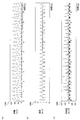
- FIG. 1 It is a figure which shows the typical waveform of the finger tap movement of one hand.
- A is a figure which shows a distance waveform.
- B is a figure which shows a velocity waveform.
- C is a figure which shows an acceleration waveform.
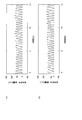
- A) is a figure which shows the distance waveform of dominant hand.
- B is a figure which shows the distance waveform of a non-dominant hand.
- (a) is a steady value corresponding to a blood pressure
- (b) is a figure which shows a pulse wave.
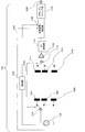
- the motor function evaluation system 1000 includes a motor function measuring device 1100 that measures the finger movement of a subject, and an evaluation that records and analyzes data measured by the motor function measuring device 1100.
- the apparatus 1200 includes an operation input unit 1300 for inputting subject information and a display unit 1400 for displaying measurement results and analysis results.
- the test subject is a measurement target by the motor function measuring apparatus 1100, and in this embodiment, is a person who undergoes a test for the presence or absence or severity of dementia.
- the motor function measuring apparatus 1100 measures the movement of the finger when the subject performs a finger motion.
- finger movement can be measured by finger tapping movement (movement that opens and closes the thumb and forefinger of the hand as fast and as large as possible) as well as the distance between the two coils. Includes all body movements.
- finger tapping movement movement that opens and closes the thumb and forefinger of the hand as fast and as large as possible
- a finger tap movement will be described as an example of the finger movement.
- the motor function measuring apparatus 1100 calculates motor data based on the relative distance between a pair of a transmitting coil and a receiving coil attached to a movable part of a living body. For example, information on a finger movement of a subject (hereinafter simply “ Also referred to as “movement information”) in a time series, and at least the subject's movement information regarding any one of distance, speed, acceleration, and jerk (acceleration time-differentiated) is time-series data. It is acquired as (waveform data).
- Motor function measuring apparatus 1100 includes sensor unit 1500 and sensor unit 1510, switching unit (1) 1110 (first switching unit) and switching unit (2) 1111 (second switching unit), AC generation unit 1120, , An amplification / filter unit 1130, an analog-digital conversion unit 1150, a time adjustment / detection unit 1160, and a downsampling unit 1170.
- the sensor unit 1500 includes a transmission coil 1501 that transmits a magnetic field and a reception coil 1511 that receives (detects) this magnetic field.
- 2A is a diagram in which the sensor unit 1500 is mounted on the left hand
- FIG. 2B is a diagram in which the sensor unit 1510 is mounted on the right hand.
- the left-hand sensor unit 1500 in FIG. 2A will be described.
- the left-hand sensor unit 1510 in FIG. The same arrangement and operation as 1500 can be performed.
- the transmitting coil 1501 is attached to the nail portion of the thumb, and the receiving coil 1511 is attached to the nail portion of the index finger, for example, with double-sided tape.
- the transmitting coil 1501 may be attached to the nail portion of the index finger and the receiving coil 1511 may be attached to the nail portion of the thumb.
- part of the transmission coil 1501 and the receiving coil 1511 is demonstrated as each nail
- the transmitting coil and the receiving coil are attached to other than the living body, the relative distance between the transmitting coil and the receiving coil is measured, the degree of magnetization of the metal and the magnetism are magnetized. It is also possible to measure the movement of the object.
- N In the case of monitoring the movement of locations, it is possible to increase the number of transmitting coil and receiving coil pairs up to N.
- transmitting coils when a plurality of transmitting coils are generically referred to, the reference numerals are omitted and simply referred to as “transmitting coils”, and when a plurality of receiving coils are collectively referred to, reference numerals are omitted. It may be simply referred to as “receiving coil”.
- one AC generation unit 1120 (AC generation circuit) is connected via a switching unit (1) 1110 (switch). Then, by the switching operation by the switching unit (1) 1110, an alternating current (for example, a current of 20 kHz) from the alternating current generating unit 1120 sequentially flows through these transmitting coils, and the transmitting coil through which the alternating current flows generates an alternating magnetic field.
- the AC generating unit 1120 generates an AC current having a predetermined frequency, and the timing at which the current flows is controlled by the control unit 1140.
- the controller 1140 causes the AC generator 1120 to perform the transmission operation only during the time during which it flows through the N transmission coils from the transmission coil (1) 1501 to the transmission coil (N) 150N. Control to do. Further, the signal generated by the AC generator 1120 is used as a reference signal 3100 for detection operation of the time adjustment / detection unit 1160.
- control unit 1140 generates a synchronization signal 3101 for controlling the switching unit (1) 1110 and the switching unit (2) 1111 (switching switch).
- the switching unit (1) 1110 and the switching unit (2) 1111 can be switched at the same time by the synchronization signal 3101 and sequentially operate for each pair of the transmitting coil and the receiving coil. That is, the control unit 1140 switches the plurality of transmission coils by the switching unit (1) 1110 and the plurality of receptions by the switching unit (2) 1111 so that the transmission coil and the reception coil that are paired sequentially operate. Switch the coil.
- N receiving coils from the receiving coil (1) 1511 to the receiving coil (N) 151N are connected to an amplification / filter unit 1130 (amplifier / filter circuit) via a switching unit (2) 1111 to An output signal from the filter unit 1130 is converted into a digital signal by an analog-digital (AD) conversion unit 1150, and the digital signal is transmitted to the time adjustment / detection unit 1160.
- AD analog-digital
- the analog-to-digital conversion by the analog-to-digital conversion unit 1150 facilitates subsequent processing (such as downsampling).
- the time adjustment / detection unit 1160 performs processing to delete the AC magnetic field waveform (noise portion) for a predetermined period immediately after switching by the switching unit (2) 1111 from the AC magnetic field waveform detected by the receiving coil (FIG. 4). Details).
- the time of deletion processing in the AC magnetic field waveform of each receiving coil is accurately controlled by the control unit 1140.
- the time adjustment / detection unit 1160 performs full-wave rectification processing and filter processing (mainly processing by a low-pass filter (LPF)) using the reference signal 3100.
- the digital signal processed by the time adjustment / detection unit 1160 is sampled by a downsampling unit 1170 at a sampling frequency that is about 1/1000 (predetermined ratio) of the sampling frequency (for example, 200 kHz) in the analog-digital conversion unit 1150. It is converted (down-sampled) into coarse data (for example, 200 Hz). As a result, the capacity of the entire data can be reduced.
- the output signal 3200 can be transmitted at high speed as data of a plurality of receiving coils even when the communication capacity is limited. That is, since the data communication unit 1600 receives a small amount of data from the downsampling unit 1170, it can transfer exercise data related to a plurality of receiving coils to the evaluation device 1200 at a time by wireless or wired.
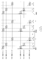
- FIG. 4 shows current waveforms in N transmitting coils from the transmitting coil (1) 1501 to the transmitting coil (N) 150N, and the lower part of FIG. 4 shows the receiving coil (1) 1511 to the receiving coil (N). Magnetic field waveforms detected by N receiving coils up to 151N are shown.
- Each transmitting coil is supplied with an alternating current for a time width T1 (for example, 50 ⁇ s (200 kHz)) (FIG. 4 shows a current waveform for four periods during the time width T1). Then, the connection of each transmitter coil is sequentially switched by the switching unit (1) 1110 (FIG. 3), and current is supplied in sequence to the Nth transmitter coil (N) 150N at intervals of T1.
- T1 for example, 50 ⁇ s (200 kHz)
- the time width T2 is, for example, 10 ms, which is a sampling time of about 100 Hz sufficient to measure the maximum frequency 10 Hz that the finger tap movement has (that is, the time width of time 1 and time 2, time 2 and time 3). Is 10 ms).
- the time width T3 is (time width T2 ⁇ time width T1 ⁇ N).
- the control unit 1140 (FIG. 3) performs control to stop the current from the AC generator 1120 to the transmitting coil.
- the relationship between these time widths is T1 ⁇ T2 and T1 ⁇ N ⁇ T3 (in FIG. 4, these relationships are not accurately described for the sake of drawing). Therefore, during the time period T3 occupying most of the time period T2, the current consumption can be suppressed by the control to stop the current from the AC generator 1120 to the transmitting coil, and power saving can be realized. .
- the N receiving coils from the receiving coil (1) 1511 to the receiving coil (N) 151N are connected by the switching unit (2) 1111 (FIG. 3) at the timing when an alternating current flows through the transmitting coils that are paired sequentially. Are switched, and a signal is input to the amplification / filter unit 1130 (FIG. 3). As shown in the lower part of FIG. 4, each reception signal (magnetic field waveform) is mixed with noise in the first part of the time. This reception noise is noise generated when the connection is switched by the switching unit (2) 1111 (FIG. 3) that switches the reception coil.
- FIG. 5 shows a case where noise is present in the first part of the switching timing.
- the upper part of FIG. 5 shows a received waveform 5100, and the lower part of FIG. 5 shows a waveform 5200 after noise removal processing.
- the waveform 5200 after the noise deletion processing in the lower part of FIG. 5 is an example in which the first one period is deleted and the time width T4 for the remaining three periods is detected as a signal component.
- This noise elimination processing can be operated by a microcomputer (time adjustment / detection unit 1160) equipped with a CPU (Central Processing Unit).
- the signal processing method of the waveform after noise removal processing will be described by taking the receiving coil 1511 as an example.
- the waveform 5200 after the noise removal processing is subjected to full-wave rectification that converts all negative signals into positive signals by the microcomputer (time adjustment / detection unit 1160), and a waveform 6100 after detection is obtained.
- the time-integrated waveform 6100 after detection is divided by the number of data points to obtain a waveform 6200 after averaging.
- a continuous motion waveform is formed by using the averaged waveform 6200 as values at time 1, time 2, and time 3 (see FIG. 4).
- the output signal 3200 shown in FIG. 3 includes, for example, the relative distance between the transmitting coil (1) 1501 and the receiving coil (2) 1511 attached to the thumb and the index finger, and the transmitting coil (2) 1502 and the receiving coil (2) 1512.
- the voltage value corresponding to the relative distance is expressed (the conversion formula between the relative distance and the voltage value will be described later).
- the evaluation device 1200 (see FIG. 1) records and analyzes data measured by the motor function measuring device 1100.
- the evaluation apparatus 1200 receives the output signal (time-series data) from the data communication unit 1600, the data processing unit 1220 that analyzes the input output signal, and the motor function measurement device 1100.
- the data processing unit 1220 calculates (generates) a motion waveform of the subject's finger tap motion based on the output signal sent from the data input unit 1210 and obtained through the control unit 1270, and the motor function ( For example, an objective index representing the severity of Parkinson's disease) or brain function (for example, dementia) is calculated.
- the motor function For example, an objective index representing the severity of Parkinson's disease
- brain function for example, dementia
- Each information is appropriately stored in the storage unit 1260.
- the data processing unit 1220 includes a motion waveform generation unit 1221 and a feature amount generation unit 1222.
- the motion waveform generation means 1221 converts the time series data (waveform data) of the voltage output sent from the motor function measuring device 1100 into a corresponding motion waveform, and time-differentiates the converted motion waveform.
- the distance waveform, the velocity waveform, and the acceleration waveform are complementarily generated by time integration or the like (details will be described later).
- the conversion formula for converting the voltage output (voltage value) into a motion waveform is, for example, a plurality of blocks having different lengths (for example, blocks having a length of 20, 30, 60 mm).
- a motion waveform such as a relative distance waveform
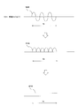
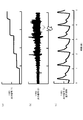
- FIG. 7 shows a distance waveform 7100 (FIG. 7A) obtained by converting the waveform data by a conversion equation, and a velocity waveform 7200 obtained by time differentiation of the distance waveform 7100 (FIG. 7B). ) And an acceleration waveform 7300 (FIG. 7C) obtained by differentiating the velocity waveform 7200 with respect to time.
- the “movement waveform” includes at least one of a distance waveform, a velocity waveform, an acceleration waveform, and a jerk waveform unless otherwise specified.
- the signal control unit 1230 (see FIG. 1) transmits a signal for starting measurement to the motor function measuring device 1100 in response to the operation signal sent from the operation input unit 1300.
- the motor function measuring apparatus 1100 is in a standby state when no measurement is performed, and enters a state where measurement is possible by a signal from the signal control means 1230.
- the subject information processing means 1240 manages the information using a subject DB (Data Base) that records information such as subject information and analysis results in the storage unit 1260. More specifically, the subject information processing means 1240 includes: 1) registration, correction, deletion, search, sorting of subject information, 2) association of subject information with measurement data, 3) registration and correction of measurement data analysis results, Deletion (addition, correction, and deletion of items), 4) When statistical processing is performed, processing of four items, mainly registration, correction, and deletion of the statistical processing results, is performed in cooperation with the subject DB.
- a subject DB Data Base
- the subject information registered in the subject DB includes subject ID (Identifier), name, date of birth, age, height, weight, disease name, comments about the subject, and the like.
- subject ID Identity
- the information management by the subject information processing means 1240 can be easily realized by a conventionally known program and data configuration.
- the output processing unit 1250 displays information such as subject information and analysis results registered in the subject DB on the display unit 1400 in a display format that is easy to visually understand using a graph or table format as appropriate. It is what is displayed. Note that the output processing unit 1250 does not need to display all the analysis results described above at the same time, and can be configured to display items appropriately selected by the operator via the operation input unit 1300.
- the control unit 1270 includes a CPU (Central Processing Unit), a ROM (Read Only Memory), a RAM (Random Access Memory), and the like.
- CPU Central Processing Unit
- ROM Read Only Memory
- RAM Random Access Memory
- the motion waveform generation unit 1221 and the feature amount generation unit 1222, the signal control unit 1230, the subject information processing unit 1240, and the output processing unit 1250 in the data processing unit 1220 store programs or data stored in the storage unit 1260. This is realized by loading the control unit 1270 and executing arithmetic processing.
- the operation input unit 1300 (see FIG. 1) is used by an operator of the motor function evaluation system 1000 to input subject information, and can be realized by a keyboard, a mouse, or the like. Further, when inputting subject information, an input screen may be displayed on the display as a user interface for assisting input by the operator.
- the display unit 1400 (see FIG. 1) outputs subject information and exercise information processed by the data processing unit 1220.
- an LCD Liquid Crystal Display
- a CRT Cathode Ray Tube
- printer etc.
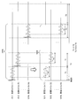
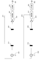
- the AC generation circuit (f1) 8301 and the AC generation circuit (f2) 8302 generate AC currents having different frequencies.
- the transmission coil (1) 8101 and the transmission coil (2) 8202 are connected to each other.
- the receiving coil (1) 8201 and the receiving coil (2) 8202 are respectively arranged for the receiving coil, and for each of them, amplifier circuits 8601 and 8602, detection circuits 8401 and 8402, and a low-pass circuit (LPF circuit) 8501. , 8502, and reference signals 8701 and 8702 are used to obtain output signals 8801 and 8802, respectively.
- FIG. 10 is a finger tap movement waveform measured simultaneously with both hands measured by the configuration of FIG. 8, (a) shows a distance waveform of a dominant hand, and (b) shows a distance waveform of a non-dominant hand. FIG. Even when the configuration of the present embodiment is used, the same waveform as in FIG. 10 can be obtained.
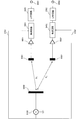
- FIG. 9 shows another conventional example of the two-channel simultaneous measurement of the comparative example (conventional technology).
- one transmission coil 9200 and one AC generation circuit 9100 are arranged, and two reception coils (1) 9301 and two reception coils (2) 9302 are arranged.
- Receiving coil (1) 9301 and receiving coil (2) 9302 are connected through amplifier circuits 9801 and 9802, detection circuits 9401 and 9402, low-pass circuits (LPF circuits) 9501 and 9502, and reference signals 9701 and 9702, respectively. Are used to obtain output signals 9601 and 9602, respectively.
- LPF circuits low-pass circuits
- FIG. 11 shows an example of a pulse wave measured with the configuration of FIG.
- the output signal (1) 11001 shows a steady value corresponding to the blood pressure.
- the output signal (2) 11002 represents a pulse wave.
- the output signal (1) 11001 at the position where the local peak of the amplitude of the output signal (2) 11002 appears is a value corresponding to the average blood pressure. Further, as shown in FIG.
- a waveform obtained by enlarging the output signal (2) 11002 is an output signal (2) enlarged waveform 11003, and the pulse wave is clearly measured (observed).
- the comparative example (prior art) shown in FIG. 8 to FIG. 11 described above since two circuit groups are arranged, simultaneous measurement at a plurality of locations on a living body is possible. In addition, the communication capacity cannot be reduced.
- the movement of the living body at a plurality of points is approximately the same time (with a time difference that can be ignored at a plurality of points (T1 ⁇ (N ⁇ 1) in FIG. 4 at the maximum)).
- T1 ⁇ (N ⁇ 1) in FIG. 4 at the maximum) since the circuit scale is small, power saving and low cost can be realized, and more than one pair consisting of a transmitter coil and a receiver coil can be switched to prevent interference between two or more receiver coils.
- the amount of data to be handled can be reduced by downsampling, data can be easily transmitted to a PC (Personal Computer) even in a wireless communication with limited communication capacity.
- PC Personal Computer
- Motor Function Evaluation System 1100 Motor Function Measuring Device 1110 Switching Unit (1) (First Switching Unit) 1111 switching unit (2) (second switching unit) 1120 AC generator 1130, amplification / filter unit 1140 control unit 1150 analog-digital conversion unit 1160 time adjustment / detection unit 1170 downsampling unit 1200 evaluation device 1210 data input unit 1220 data processing unit 1221 motion waveform generation unit 1222 feature quantity generation unit 1230 Signal control unit 1240 Subject information processing unit 1250 Output processing unit 1260 Storage unit 1270 Control unit 1300 Operation input unit 1400 Display unit 1500, 1510 Sensor unit 1501, 1502, 150N Transmitting coil 1511, 1512, 151N Reception coil 1600 Data communication unit
Abstract
The present invention addresses the problem of limiting power consumption and radio wave interference when assessing the movements of multiple sites of a living body. The present invention is a movement function assessment system (1000) provided with: a movement function measurement apparatus (1100) for calculating movement data on the basis of the relative distances of pairs of transmission coils (1501 (1502)) and reception coils (1511 (1512)) attached to movable portions of a living body; and an assessment apparatus (1200) for assessing the movement function of the living body on the basis of the movement data received from the movement function measurement apparatus (1100). A control unit (1140) of the movement function measurement apparatus (1100) performs the switching of the multiple transmission coils (1501 (1502)) by a switching unit (1) (1110) and the switching of the multiple reception coils (1511 (1512)) by a switching unit (2) (1111) so that the paired transmission coils (1501 (1502)) and reception coils (1511 (1512)) are operated sequentially.
Description
本発明は、生体の運動機能を評価する技術に関する。
The present invention relates to a technique for evaluating a motor function of a living body.
近年、日本では、認知症、パーキンソン病、脳卒中などの脳神経疾患の患者(以下、「脳神経疾患患者」という。)が急増している。例えば、パーキンソン病は、振戦(ふるえ)、筋強剛(筋肉の緊張が高まっている状態のひとつ)、姿勢反射障害(姿勢の立て直し不良)、寡動(動作の鈍化)の4つを主要徴候とする脳神経疾患である。また、認知症に関しては、日本国内に200万人もの認知症患者がいると言われており、記憶障害、見当識障害、学習障害などが生じ、日常生活に大きな支障を来たす。認知症においても、末期には、小刻み歩行や前傾姿勢などの運動障害が表れ、最終的には寝たきり状態に陥る。
In recent years, the number of patients with cranial nerve diseases such as dementia, Parkinson's disease, and stroke (hereinafter referred to as “brain nerve disease patients”) is rapidly increasing in Japan. For example, Parkinson's disease has four main symptoms: tremor, tremor (one of the conditions in which muscle tension is increased), postural reflex disorder (poor posture repositioning), and peristalsis (motion dullness). It is a cranial nerve disease. As for dementia, it is said that there are 2 million patients with dementia in Japan, which causes memory impairment, disorientation, learning disability, etc., which greatly hinders daily life. Even in dementia, at the end, movement disorders such as small gait and leaning forward appear, and eventually fall into a bedridden state.
人間の運動は、脳からの運動指令が電気信号として神経系を伝わり、それを受けて筋肉が収縮することで実現される。しかし、脳神経疾患患者の場合、脳からの運動指令が電気信号として神経系に正常に伝わらないため、身体の状態や動作に異常が発生する。
脳神経疾患患者の急増は、医療費の増大だけでなく、それらの患者が就労不能であることによる大きな社会的損失も招くことになる。したがって、このような脳神経疾患による社会的問題を解決するには、被験者が脳神経疾患か否か、また、脳神経疾患である場合はその度合いを、ある程度以上の精度で判定することが必要となる。 Human movement is realized by the movement command from the brain being transmitted to the nervous system as an electrical signal and the muscles contracting in response to it. However, in the case of a patient with cranial nerve disease, since an exercise command from the brain is not normally transmitted to the nervous system as an electrical signal, an abnormality occurs in the body state or movement.
The rapid increase in patients with cranial nerve disease not only increases medical costs, but also causes great social loss due to the inability to work for those patients. Therefore, in order to solve such a social problem caused by a cranial nerve disease, it is necessary to determine whether or not the subject has a cranial nerve disease and, if it is a cranial nerve disease, the degree thereof with a certain degree of accuracy.
しかし、被験者が脳神経疾患か否かや、その度合いは、血液検査やMRI(Magnetic Resonance Imaging)の画像所見などで判定することが難しい。なぜなら、脳神経疾患患者と健常者との差異が必ずしも明確ではないからである。したがって、被験者が脳神経疾患か否かや、その度合いは、検査者である医師の経験や能力によって主観的に判断されることも少なくない。そういった背景の中で、例えば、パーキンソン病による運動機能低下や調律異常を評価するために、手の指の運動をモニタする指運動テストが行なわれるようになってきた。
However, it is difficult to determine whether or not a subject has a cranial nerve disease and the degree thereof by a blood test or MRI (Magnetic Resonance Imaging) image findings. This is because the difference between a patient with cranial nerve disease and a healthy person is not always clear. Accordingly, it is often the case that whether or not the subject has a cranial nerve disease and the degree thereof are subjectively determined by the experience and ability of the doctor who is the examiner. Against this background, for example, in order to evaluate motor function deterioration and rhythm abnormalities due to Parkinson's disease, a finger movement test for monitoring finger movement of hands has been performed.
この指運動をモニタする方法として、例えば、電気スイッチ、金属ループ、キーボード、3次元カメラなどを使用した方法が考案されている。しかし、これらの方法は簡易な方法とは言えず、充分普及していない。
As a method for monitoring this finger movement, for example, a method using an electrical switch, a metal loop, a keyboard, a three-dimensional camera, etc. has been devised. However, these methods cannot be said to be simple methods and are not sufficiently widespread.
そこで、本出願人は、磁気センサを用いて、生体の部位の動き(例えば、片手の二指(親指と人差し指)の連続開閉動作(以下、「指タップ運動」という。))を検出することが可能な生体検査装置を提案している(特許文献1参照)。特許文献1の技術によれば、指タップ運動から得た情報を解析して被験者の二指の動きを認識することで、脳神経疾患患者か健常者かを高精度で判定することができる。
Therefore, the present applicant uses a magnetic sensor to detect a movement of a part of a living body (for example, continuous opening / closing operation of two fingers (thumb and forefinger) of one hand (hereinafter referred to as “finger tap movement”)). Has been proposed (see Patent Document 1). According to the technique of Patent Document 1, it is possible to determine with high accuracy whether the patient is a cranial nerve disease patient or a healthy person by analyzing the information obtained from the finger tap movement and recognizing the movement of the subject's two fingers.
一方、車両の幅方向の変位を電子的に検出する方法として、同一周波数の励磁電源を用いて、各受信コイルを切替え接続し、時分割により受信コイルの検出信号を得る手法が開示されている(特許文献2参照)。この特許文献2の技術では、水晶発信子の出力信号を増幅した後、切替スイッチを介して励磁コイルに供給している。この手法を用いると、現在の車両の走行位置などのマーカ情報および車両の幅方向の変位を電子的に検出し得る電子式車両位置検出システムを提供できるとされている。
On the other hand, as a method for electronically detecting the displacement in the width direction of the vehicle, a method is disclosed in which each receiving coil is switched and connected using an excitation power source of the same frequency, and a detection signal of the receiving coil is obtained by time division. (See Patent Document 2). In the technique of Patent Document 2, the output signal of the crystal oscillator is amplified and then supplied to the exciting coil via the changeover switch. If this method is used, it is said that an electronic vehicle position detection system capable of electronically detecting marker information such as the current vehicle traveling position and displacement in the width direction of the vehicle can be provided.
しかしながら、特許文献1の技術における構成(片手ごとに計測回路を有する構成)では、両手の動きを同時に計測するために、それぞれの手に対応する異なる周波数を有する発信機を2つ配置し、検出回路もそれぞれの手に対応して2つ配置する必要があるため、回路規模が大きくなり消費電力も大きくなる。そのため、電池駆動の携帯型装置に適用する場合、短時間での測定しか実現できないため、実用的でない。また、特許文献1の手法では、異なる周波数を用いることで、左右の手の動きの検出時の混信(干渉)を防ぐ手法をとっているが、両手が非常に近接した場合、混信(干渉)を生じる可能性がある。
However, in the configuration in the technique of Patent Document 1 (configuration having a measurement circuit for each hand), two transmitters having different frequencies corresponding to each hand are arranged and detected in order to simultaneously measure the movements of both hands. Since it is necessary to arrange two circuits corresponding to each hand, the circuit scale increases and the power consumption also increases. For this reason, when applied to a battery-driven portable device, only measurement in a short time can be realized, which is not practical. Further, in the technique of Patent Document 1, a technique of preventing interference (interference) at the time of detecting the left and right hand movements by using different frequencies is used. However, when both hands are very close to each other, interference (interference) occurs. May occur.
また、特許文献2の技術では、車両の幅方向の変位を電子的に検出するという課題を解決するために、数mから数十m単位で配置されているマーカの位置情報を得る構成であるため、複数計測点での時間的な同時性や連続性は必要でない。そのため、複数点でほぼ同時刻に連続的な波形を検出することはできない。さらに、車の位置検出のための該複数点は互いに数mから数十mも離れており、各測定点間での干渉(クロストーク)は起こらないため、クロストークや雑音混入を防ぐ構成は考えられていない。消費電力についても、車載の場合は制限が少ないため、消費電力を抑える工夫は行われていない。
Moreover, in the technique of patent document 2, in order to solve the subject of detecting the displacement of the width direction of a vehicle electronically, it is the structure which acquires the positional information on the marker arrange | positioned by several m to several dozen m unit. Therefore, temporal simultaneity and continuity at multiple measurement points are not necessary. Therefore, a continuous waveform cannot be detected at a plurality of points at substantially the same time. Furthermore, the multiple points for detecting the position of the car are several meters to several tens of meters away from each other, and no interference (crosstalk) occurs between the measurement points. Not considered. As for power consumption, since there are few restrictions in the case of in-vehicle use, no measures for reducing power consumption have been made.
そこで、本発明は、生体の複数箇所の運動を評価する際に、消費電力と電波干渉を抑えることを課題とする。
Therefore, an object of the present invention is to suppress power consumption and radio wave interference when evaluating the motion of a plurality of locations of a living body.
前記課題を解決するために、本発明は、生体の可動部分に取り付けた発信コイルと受信コイルのペアの相対距離に基づいて運動データを算出する運動機能測定装置と、運動機能測定装置から受信した運動データに基づいて生体の運動機能を評価する評価装置と、を備える運動機能評価システムである。運動機能測定装置は、所定周波数の交流電流を発生する交流発生部と、複数の発信コイルと、交流発生部および複数の発信コイルと接続され、交流発生部が発生した交流電流を複数の発信コイルそれぞれに順番に流すように切り替える第1の切替部と、複数の発信コイルそれぞれに1対1対応で設けられ、ペアの発信コイルが発生する磁場を検出する複数の受信コイルと、複数の受信コイルと接続される第2の切替部と、複数の受信コイルに、第2の切替部を介して接続される増幅・フィルタ部と、増幅・フィルタ部と接続され、交流発生部からの参照信号を用いて検波を行う時間調整・検波部と、ペアとなっている発信コイルと受信コイルが順次動作するように、第1の切替部による複数の発信コイルの切り替え、および、第2の切替部による複数の受信コイルの切り替え、を行う制御部と、を備える。その他の手段については後記する。
In order to solve the above-mentioned problems, the present invention has received from a motor function measuring device and a motor function measuring device that calculates motor data based on a relative distance between a pair of a transmitting coil and a receiving coil attached to a movable part of a living body. A motor function evaluation system comprising: an evaluation device that evaluates a motor function of a living body based on motor data. The motor function measuring device is connected to an AC generator that generates an alternating current of a predetermined frequency, a plurality of transmitter coils, an AC generator and a plurality of transmitter coils, and the AC generator generates the AC current generated by the AC generator. A first switching unit that switches the flow so as to flow in sequence, a plurality of reception coils that are provided in a one-to-one correspondence with each of the plurality of transmission coils, and that detect a magnetic field generated by the pair of transmission coils, and a plurality of reception coils A second switching unit connected to the plurality of receiving coils, an amplification / filter unit connected to the plurality of receiving coils via the second switching unit, an amplification / filter unit, and a reference signal from the AC generation unit Use the time adjustment / detection unit to perform detection, and switch the plurality of transmission coils by the first switching unit and the second switching unit so that the paired transmission coil and reception coil operate sequentially. That includes the switching of the plurality of receiving coils, and a control unit for performing a. Other means will be described later.
本発明によれば、生体の複数箇所の運動を評価する際に、消費電力と電波干渉を抑えることができる。
According to the present invention, it is possible to suppress power consumption and radio wave interference when evaluating the motion of a plurality of locations of a living body.
以下、本発明を実施するための形態(以下「実施形態」という。)について、図面を参照して詳細に説明する。
Hereinafter, modes for carrying out the present invention (hereinafter referred to as “embodiments”) will be described in detail with reference to the drawings.
[全体構成]
図1に示すように、本実施形態に係る運動機能評価システム1000は、被験者の手指運動を測定する運動機能測定装置1100と、運動機能測定装置1100によって測定されたデータの記録及び解析を行う評価装置1200と、被験者の情報などを入力する操作入力部1300と、測定結果や解析結果などを表示する表示部1400と、を含んで構成される。 [overall structure]
As shown in FIG. 1, the motorfunction evaluation system 1000 according to the present embodiment includes a motor function measuring device 1100 that measures the finger movement of a subject, and an evaluation that records and analyzes data measured by the motor function measuring device 1100. The apparatus 1200 includes an operation input unit 1300 for inputting subject information and a display unit 1400 for displaying measurement results and analysis results.
図1に示すように、本実施形態に係る運動機能評価システム1000は、被験者の手指運動を測定する運動機能測定装置1100と、運動機能測定装置1100によって測定されたデータの記録及び解析を行う評価装置1200と、被験者の情報などを入力する操作入力部1300と、測定結果や解析結果などを表示する表示部1400と、を含んで構成される。 [overall structure]
As shown in FIG. 1, the motor
ここで、被験者とは、運動機能測定装置1100による測定対象であり、本実施形態においては、認知症の有無または重症度の検査を受ける人である。
また、運動機能測定装置1100は、被験者に手指運動を行わせた際の指の動作を測定するものである。ここで、手指運動とは、磁気センサによって計測された指タップ運動(手の親指と人差し指を可能な限り速く、かつ可能な限り大きく繰り返し開閉させる運動)や、そのほか2つのコイル間距離で計測できる生体の運動を全て含む。以下、手指運動として、指タップ運動を例にとって説明する。 Here, the test subject is a measurement target by the motorfunction measuring apparatus 1100, and in this embodiment, is a person who undergoes a test for the presence or absence or severity of dementia.
The motorfunction measuring apparatus 1100 measures the movement of the finger when the subject performs a finger motion. Here, finger movement can be measured by finger tapping movement (movement that opens and closes the thumb and forefinger of the hand as fast and as large as possible) as well as the distance between the two coils. Includes all body movements. Hereinafter, a finger tap movement will be described as an example of the finger movement.
また、運動機能測定装置1100は、被験者に手指運動を行わせた際の指の動作を測定するものである。ここで、手指運動とは、磁気センサによって計測された指タップ運動(手の親指と人差し指を可能な限り速く、かつ可能な限り大きく繰り返し開閉させる運動)や、そのほか2つのコイル間距離で計測できる生体の運動を全て含む。以下、手指運動として、指タップ運動を例にとって説明する。 Here, the test subject is a measurement target by the motor
The motor
[運動機能測定装置の概要]
運動機能測定装置1100は、生体の可動部分に取り付けた発信コイルと受信コイルのペアの相対距離に基づいて運動データを算出するものであって、例えば、被験者の手指運動の情報(以下、単に「運動情報」ともいう。)を時系列に検出するものであり、少なくとも、距離、速度、加速度、躍度(加速度を時間微分したもの)のいずれか1つに関する被験者の運動情報を、時系列データ(波形データ)として取得するものである。 [Outline of motor function measuring device]
The motorfunction measuring apparatus 1100 calculates motor data based on the relative distance between a pair of a transmitting coil and a receiving coil attached to a movable part of a living body. For example, information on a finger movement of a subject (hereinafter simply “ Also referred to as “movement information”) in a time series, and at least the subject's movement information regarding any one of distance, speed, acceleration, and jerk (acceleration time-differentiated) is time-series data. It is acquired as (waveform data).
運動機能測定装置1100は、生体の可動部分に取り付けた発信コイルと受信コイルのペアの相対距離に基づいて運動データを算出するものであって、例えば、被験者の手指運動の情報(以下、単に「運動情報」ともいう。)を時系列に検出するものであり、少なくとも、距離、速度、加速度、躍度(加速度を時間微分したもの)のいずれか1つに関する被験者の運動情報を、時系列データ(波形データ)として取得するものである。 [Outline of motor function measuring device]
The motor
運動機能測定装置1100は、センサ部1500およびセンサ部1510と、切替部(1)1110(第1の切替部)および切替部(2)1111(第2の切替部)と、交流発生部1120と、増幅・フィルタ部1130と、アナログデジタル変換部1150と、時間調整・検波部1160と、ダウンサンプリング部1170とを備えて構成される。
Motor function measuring apparatus 1100 includes sensor unit 1500 and sensor unit 1510, switching unit (1) 1110 (first switching unit) and switching unit (2) 1111 (second switching unit), AC generation unit 1120, , An amplification / filter unit 1130, an analog-digital conversion unit 1150, a time adjustment / detection unit 1160, and a downsampling unit 1170.
≪センサ部(運動センサ)≫
図2(a)に示すように、センサ部1500は、磁場を発信する発信コイル1501と、この磁場を受信(検出)する受信コイル1511によって構成される。なお、図2(a)は、センサ部1500を左手に装着した図であり、図2(b)は、センサ部1510を右手に装着した図である。以下の説明では、説明の簡略化のため、図2(a)の左手用のセンサ部1500のみで説明を行うが、図2(b)の右手用のセンサ部1510においても左手用のセンサ部1500と全く同様の配置、動作などが可能である。 ≪Sensor part (motion sensor) ≫
As shown in FIG. 2A, thesensor unit 1500 includes a transmission coil 1501 that transmits a magnetic field and a reception coil 1511 that receives (detects) this magnetic field. 2A is a diagram in which the sensor unit 1500 is mounted on the left hand, and FIG. 2B is a diagram in which the sensor unit 1510 is mounted on the right hand. In the following description, for simplification of description, only the left-hand sensor unit 1500 in FIG. 2A will be described. However, the left-hand sensor unit 1510 in FIG. The same arrangement and operation as 1500 can be performed.
図2(a)に示すように、センサ部1500は、磁場を発信する発信コイル1501と、この磁場を受信(検出)する受信コイル1511によって構成される。なお、図2(a)は、センサ部1500を左手に装着した図であり、図2(b)は、センサ部1510を右手に装着した図である。以下の説明では、説明の簡略化のため、図2(a)の左手用のセンサ部1500のみで説明を行うが、図2(b)の右手用のセンサ部1510においても左手用のセンサ部1500と全く同様の配置、動作などが可能である。 ≪Sensor part (motion sensor) ≫
As shown in FIG. 2A, the
図2(a)に示すように、発信コイル1501は親指の爪部に、受信コイル1511は人差し指の爪部に、例えば両面テープなどによって、それぞれ装着される。なお、取り付ける指を逆にして、発信コイル1501を人差し指の爪部に、受信コイル1511を親指の爪部に装着してもよい。
As shown in FIG. 2A, the transmitting coil 1501 is attached to the nail portion of the thumb, and the receiving coil 1511 is attached to the nail portion of the index finger, for example, with double-sided tape. Alternatively, the transmitting coil 1501 may be attached to the nail portion of the index finger and the receiving coil 1511 may be attached to the nail portion of the thumb.
また、発信コイル1501と受信コイル1511の被装着部位は、親指と人差し指のそれぞれの爪部として説明しているが、これに限定されるものではなく、例えば、爪部以外の指部分であってもよい。
また、親指と人差し指に限定されることなく、例えば、親指と小指などの別の組み合わせの指に装着してもよい。さらに、被装着部位は被験者の爪部又は指に限定されることなく、例えば、指に近接する手のひらなどの周辺部位も含まれる。したがって、発信コイル1501と受信コイル1511の被装着部位は、指タップ運動を検出できるのであれば、被験者の爪部、指、および指の周辺部位のいずれでもよい。さらに、本実施形態では生体への装着で説明しているが、発信コイルと受信コイルを生体以外に取り付けて、発信コイルと受信コイル間の相対距離の測定、金属の磁化の度合いや磁化された物体の動きの測定を行うことも可能である。 Moreover, although the attachment site | part of thetransmission coil 1501 and the receiving coil 1511 is demonstrated as each nail | claw part of a thumb and forefinger, it is not limited to this, For example, it is finger parts other than a nail | claw part. Also good.
Further, the present invention is not limited to the thumb and the index finger, and may be attached to another combination of fingers such as the thumb and the little finger. Further, the wearing site is not limited to the nail part or finger of the subject, and includes, for example, a peripheral site such as a palm close to the finger. Therefore, as long as the finger tapping motion can be detected, the wearing portions of the transmittingcoil 1501 and the receiving coil 1511 may be any of the nail portion of the subject, the finger, and the peripheral portion of the finger. Furthermore, although this embodiment has been described with attachment to a living body, the transmitting coil and the receiving coil are attached to other than the living body, the relative distance between the transmitting coil and the receiving coil is measured, the degree of magnetization of the metal and the magnetism are magnetized. It is also possible to measure the movement of the object.
また、親指と人差し指に限定されることなく、例えば、親指と小指などの別の組み合わせの指に装着してもよい。さらに、被装着部位は被験者の爪部又は指に限定されることなく、例えば、指に近接する手のひらなどの周辺部位も含まれる。したがって、発信コイル1501と受信コイル1511の被装着部位は、指タップ運動を検出できるのであれば、被験者の爪部、指、および指の周辺部位のいずれでもよい。さらに、本実施形態では生体への装着で説明しているが、発信コイルと受信コイルを生体以外に取り付けて、発信コイルと受信コイル間の相対距離の測定、金属の磁化の度合いや磁化された物体の動きの測定を行うことも可能である。 Moreover, although the attachment site | part of the
Further, the present invention is not limited to the thumb and the index finger, and may be attached to another combination of fingers such as the thumb and the little finger. Further, the wearing site is not limited to the nail part or finger of the subject, and includes, for example, a peripheral site such as a palm close to the finger. Therefore, as long as the finger tapping motion can be detected, the wearing portions of the transmitting
[運動機能測定装置の詳細]
図3に示すように、運動機能測定装置1100は、発信コイル(1)1501から発信コイル(N)150NまでN個配置し、それぞれの発信コイルに対応する受信コイル(1)1511から受信コイル(N)151NまでN個配置している。つまり、発信コイル(1)1501のペアは受信コイル(1)1511であり、発信コイル(2)1502のペアは受信コイル(2)1512であり、発信コイル(N)150Nのペアは受信コイル(N)151Nである。通常の指タップ運動は人差し指と親指の運動を計測するため、N=2(つまり、図3では発信コイル(2)1502と受信コイル(2)1512のペアまで)となるが、指などの複数(N)箇所の動きをモニタする場合では、N個まで発信コイルと受信コイルのペアを増加させることができる。なお、本実施形態での説明において、複数の発信コイルを総称するときなどに符号を省略して単に「発信コイル」と称し、また、複数の受信コイルを総称するときなどに符号を省略して単に「受信コイル」と称する場合がある。 [Details of the motor function measuring device]
As shown in FIG. 3, the motorfunction measuring device 1100 is arranged with N pieces from the transmission coil (1) 1501 to the transmission coil (N) 150N, and from the reception coil (1) 1511 corresponding to each transmission coil ( N) N are arranged up to 151N. That is, the pair of the transmission coil (1) 1501 is the reception coil (1) 1511, the pair of the transmission coil (2) 1502 is the reception coil (2) 1512, and the pair of the transmission coil (N) 150N is the reception coil ( N) 151N. Since the normal finger tap movement measures the movement of the index finger and thumb, N = 2 (that is, up to a pair of the transmission coil (2) 1502 and the reception coil (2) 1512 in FIG. 3). (N) In the case of monitoring the movement of locations, it is possible to increase the number of transmitting coil and receiving coil pairs up to N. In the description of the present embodiment, when a plurality of transmitting coils are generically referred to, the reference numerals are omitted and simply referred to as “transmitting coils”, and when a plurality of receiving coils are collectively referred to, reference numerals are omitted. It may be simply referred to as “receiving coil”.
図3に示すように、運動機能測定装置1100は、発信コイル(1)1501から発信コイル(N)150NまでN個配置し、それぞれの発信コイルに対応する受信コイル(1)1511から受信コイル(N)151NまでN個配置している。つまり、発信コイル(1)1501のペアは受信コイル(1)1511であり、発信コイル(2)1502のペアは受信コイル(2)1512であり、発信コイル(N)150Nのペアは受信コイル(N)151Nである。通常の指タップ運動は人差し指と親指の運動を計測するため、N=2(つまり、図3では発信コイル(2)1502と受信コイル(2)1512のペアまで)となるが、指などの複数(N)箇所の動きをモニタする場合では、N個まで発信コイルと受信コイルのペアを増加させることができる。なお、本実施形態での説明において、複数の発信コイルを総称するときなどに符号を省略して単に「発信コイル」と称し、また、複数の受信コイルを総称するときなどに符号を省略して単に「受信コイル」と称する場合がある。 [Details of the motor function measuring device]
As shown in FIG. 3, the motor
本実施形態ではN個までペアが増加した場合で説明を行う。発信コイル(1)1501から発信コイル(N)150Nまでには、1つの交流発生部1120(交流発生回路)が切替部(1)1110(切替スイッチ)を介して接続されている。そして、切替部(1)1110による切り替え動作により、交流発生部1120からの交流電流(例えば20kHzの電流)がそれらの発信コイルに順次流れ、交流電流が流れた発信コイルは交流磁場を発生させる。交流発生部1120は、所定周波数の交流電流を発生するものであり、制御部1140によって、電流を流すタイミングを制御される。具体的には、省電力にするため、制御部1140は、発信コイル(1)1501から発信コイル(N)150NまでのN個の発信コイルに流す間の時間のみ、交流発生部1120が発信動作するように制御する。さらに、交流発生部1120が発生する信号は時間調整・検波部1160の検波動作の参照信号3100として使用される。
In this embodiment, the case where the number of pairs increases to N will be described. From the transmission coil (1) 1501 to the transmission coil (N) 150N, one AC generation unit 1120 (AC generation circuit) is connected via a switching unit (1) 1110 (switch). Then, by the switching operation by the switching unit (1) 1110, an alternating current (for example, a current of 20 kHz) from the alternating current generating unit 1120 sequentially flows through these transmitting coils, and the transmitting coil through which the alternating current flows generates an alternating magnetic field. The AC generating unit 1120 generates an AC current having a predetermined frequency, and the timing at which the current flows is controlled by the control unit 1140. Specifically, in order to save power, the controller 1140 causes the AC generator 1120 to perform the transmission operation only during the time during which it flows through the N transmission coils from the transmission coil (1) 1501 to the transmission coil (N) 150N. Control to do. Further, the signal generated by the AC generator 1120 is used as a reference signal 3100 for detection operation of the time adjustment / detection unit 1160.
また、制御部1140は、切替部(1)1110と切替部(2)1111(切替スイッチ)を制御するための同期信号3101を発生する。同期信号3101によって切替部(1)1110と切替部(2)1111は同時に切り替わることができ、発信コイルと受信コイルのペアごとに順次動作する。つまり、制御部1140は、ペアとなっている発信コイルと受信コイルが順次動作するように、切替部(1)1110による複数の発信コイルの切り替え、および、切替部(2)1111による複数の受信コイルの切り替え、を行う。
Also, the control unit 1140 generates a synchronization signal 3101 for controlling the switching unit (1) 1110 and the switching unit (2) 1111 (switching switch). The switching unit (1) 1110 and the switching unit (2) 1111 can be switched at the same time by the synchronization signal 3101 and sequentially operate for each pair of the transmitting coil and the receiving coil. That is, the control unit 1140 switches the plurality of transmission coils by the switching unit (1) 1110 and the plurality of receptions by the switching unit (2) 1111 so that the transmission coil and the reception coil that are paired sequentially operate. Switch the coil.
また、受信コイル(1)1511から受信コイル(N)151NまでのN個の受信コイルは、切替部(2)1111を介して増幅・フィルタ部1130(アンプ・フィルタ回路)に接続され、増幅・フィルタ部1130からの出力信号は、アナログデジタル(AD)変換部1150によってデジタル信号に変換され、時間調整・検波部1160にそのデジタル信号が伝達される。なお、アナログデジタル変換部1150によるアナログデータのデジタルデータ化によって、その後の処理(ダウンサンプリングなど)が容易になる。時間調整・検波部1160では、受信コイルで検出された交流磁場波形のうち、切替部(2)1111による切り替え直後の所定周期分の交流磁場波形(ノイズ部分)を削除する処理を行う(図4で詳細を説明)。
N receiving coils from the receiving coil (1) 1511 to the receiving coil (N) 151N are connected to an amplification / filter unit 1130 (amplifier / filter circuit) via a switching unit (2) 1111 to An output signal from the filter unit 1130 is converted into a digital signal by an analog-digital (AD) conversion unit 1150, and the digital signal is transmitted to the time adjustment / detection unit 1160. Note that the analog-to-digital conversion by the analog-to-digital conversion unit 1150 facilitates subsequent processing (such as downsampling). The time adjustment / detection unit 1160 performs processing to delete the AC magnetic field waveform (noise portion) for a predetermined period immediately after switching by the switching unit (2) 1111 from the AC magnetic field waveform detected by the receiving coil (FIG. 4). Details).
また、各受信コイルの交流磁場波形における削除処理の時刻は、制御部1140によって正確に制御される。この削除処理のあと、時間調整・検波部1160は、参照信号3100を用いて全波整流処理およびフィルタ処理(主に、低域通過フィルタ(LPF)による処理)を行う。最後に、時間調整・検波部1160で処理されたデジタル信号は、ダウンサンプリング部1170によって、アナログデジタル変換部1150でのサンプリング周波数(例えば200kHz)の1000分の1程度(所定の割合)のサンプリング周波数(例えば200Hz)の粗いデータへと変換(ダウンサンプリング)される。これにより、データ全体の容量を小さくすることが可能となる。したがって、出力信号3200は、通信容量に制限がある中でも複数の受信コイルのデータとして、高速送信が可能となる。つまり、データ通信部1600は、ダウンサンプリング部1170から受信するデータ量が小さいので、複数の受信コイルに関する運動データを、無線または有線により、評価装置1200に一度に受け渡すことができる。
Also, the time of deletion processing in the AC magnetic field waveform of each receiving coil is accurately controlled by the control unit 1140. After this deletion processing, the time adjustment / detection unit 1160 performs full-wave rectification processing and filter processing (mainly processing by a low-pass filter (LPF)) using the reference signal 3100. Finally, the digital signal processed by the time adjustment / detection unit 1160 is sampled by a downsampling unit 1170 at a sampling frequency that is about 1/1000 (predetermined ratio) of the sampling frequency (for example, 200 kHz) in the analog-digital conversion unit 1150. It is converted (down-sampled) into coarse data (for example, 200 Hz). As a result, the capacity of the entire data can be reduced. Therefore, the output signal 3200 can be transmitted at high speed as data of a plurality of receiving coils even when the communication capacity is limited. That is, since the data communication unit 1600 receives a small amount of data from the downsampling unit 1170, it can transfer exercise data related to a plurality of receiving coils to the evaluation device 1200 at a time by wireless or wired.
図4の上段は、発信コイル(1)1501から発信コイル(N)150NまでN個の発信コイルでの電流波形を示し、図4の下段は、受信コイル(1)1511から受信コイル(N)151NまでN個の受信コイルで検出した磁場波形を示している。各発信コイルには時間幅T1(例えば50μs(200kHz))の間、交流電流が流されている(図4では時間幅T1の間に4周期分の電流波形が示されている)。そして、切替部(1)1110(図3)により各発信コイルの接続が順次切り替えられ、T1間隔で順番にN番目の発信コイル(N)150Nまで電流が流されている。
The upper part of FIG. 4 shows current waveforms in N transmitting coils from the transmitting coil (1) 1501 to the transmitting coil (N) 150N, and the lower part of FIG. 4 shows the receiving coil (1) 1511 to the receiving coil (N). Magnetic field waveforms detected by N receiving coils up to 151N are shown. Each transmitting coil is supplied with an alternating current for a time width T1 (for example, 50 μs (200 kHz)) (FIG. 4 shows a current waveform for four periods during the time width T1). Then, the connection of each transmitter coil is sequentially switched by the switching unit (1) 1110 (FIG. 3), and current is supplied in sequence to the Nth transmitter coil (N) 150N at intervals of T1.
時間幅T2は、例えば、指タップ運動などが有する最大周波数10Hzを計測するのに十分な100Hz程度のサンプリング時間である10msとする(つまり、時刻1と時刻2の時間幅と時刻2と時刻3の時間幅は10msとなる)。時間幅T3は(時間幅T2-時間幅T1×N)であり、時間幅T3の間は交流発生部1120から発信コイルへの電流を停止する制御を制御部1140(図3)で行う。これらの時間幅の関係は、T1<<T2、T1×N<<T3である(図4では、作図の都合上、それらの関係を正確に表記していない)。したがって、時間幅T2の中の大半の時間を占める時間幅T3の間、交流発生部1120から発信コイルへの電流を停止する制御により消費電流を抑えることができ、省電力を実現することができる。
The time width T2 is, for example, 10 ms, which is a sampling time of about 100 Hz sufficient to measure the maximum frequency 10 Hz that the finger tap movement has (that is, the time width of time 1 and time 2, time 2 and time 3). Is 10 ms). The time width T3 is (time width T2−time width T1 × N). During the time width T3, the control unit 1140 (FIG. 3) performs control to stop the current from the AC generator 1120 to the transmitting coil. The relationship between these time widths is T1 << T2 and T1 × N << T3 (in FIG. 4, these relationships are not accurately described for the sake of drawing). Therefore, during the time period T3 occupying most of the time period T2, the current consumption can be suppressed by the control to stop the current from the AC generator 1120 to the transmitting coil, and power saving can be realized. .
一方、受信コイル(1)1511から受信コイル(N)151NまでのN個の受信コイルについて、順次、ペアとなる発信コイルに交流電流が流れるタイミングで切替部(2)1111(図3)による接続が切り替えられ、増幅・フィルタ部1130(図3)に信号が入力される。図4の下段に示すように、各受信信号(磁場波形)は時刻の最初の部分にノイズが混入してしまっている。この受信ノイズは、受信コイルを切り替える切替部(2)1111(図3)によって接続が切り替えられことにより発生するノイズである。
On the other hand, the N receiving coils from the receiving coil (1) 1511 to the receiving coil (N) 151N are connected by the switching unit (2) 1111 (FIG. 3) at the timing when an alternating current flows through the transmitting coils that are paired sequentially. Are switched, and a signal is input to the amplification / filter unit 1130 (FIG. 3). As shown in the lower part of FIG. 4, each reception signal (magnetic field waveform) is mixed with noise in the first part of the time. This reception noise is noise generated when the connection is switched by the switching unit (2) 1111 (FIG. 3) that switches the reception coil.
これはすべてのチャンネル(受信コイル)の信号をほぼ同時に検出するために、受信コイルの信号間に時間差をつけずに計測するために生じる問題である。仮に数mから数十mはなれた位置での車の通過などの計測では、このように受信コイルの信号間に時間差を設けることができるため、このような問題は生じない。また、受信コイルとアンプの間にフィルタ回路を入れる方法も手法も考えられるが、例えば20kHzであると1周期が50μsと非常に短いため、フィルタによる遅延時間のほうが長くなり実用的ではない。また、省電力にするためにはなるべく各発信コイルの発信時間を短くして時間幅T3を長くする必要があり、受信コイルおよび発信コイルのT1を短くして、時間差なく各チャンネル(受信コイル、発信コイル)を切り替えていく必要がある。
This is a problem that arises because the signals of all the channels (receiver coils) are detected almost simultaneously, and measurement is performed without making a time difference between the signals of the receiver coils. In the measurement such as the passing of a car at a position separated from several meters to several tens of meters, such a problem does not occur because a time difference can be provided between the signals of the receiving coil in this way. Although a method of inserting a filter circuit between the receiving coil and the amplifier is also conceivable, for example, at 20 kHz, one period is as very short as 50 μs, so the delay time by the filter becomes longer and is not practical. Further, in order to save power, it is necessary to shorten the transmission time of each transmission coil and increase the time width T3 as much as possible. The T1 of the reception coil and the transmission coil is shortened so that each channel (reception coil, It is necessary to switch the transmission coil.
時間調整・検波部1160の時間調整機能によって、受信コイルで検出されたノイズ成分を削除する処理について、図5を用いて詳細に説明する(図1なども参照)。交流発生部1120で発生した交流電流が流れる発信コイルによって誘起された磁場は、ペアとなる受信コイルで検出される。このとき、受信コイルは切替部(2)1111(図3)によって接続が順次切り替えられるため、切替ノイズが発生する。図5では切替のタイミングの最初の部分にノイズが入っている場合を示しており、図5の上段に受信波形5100を示し、図5の下段にノイズ削除処理後の波形5200を示している。図5の下段のノイズ削除処理後の波形5200は、最初の1周期分を削除し、残りの3周期分の時間幅T4を信号成分として検出した例である。このノイズ削除処理はCPU(Central Processing Unit)を搭載しているマイコン(時間調整・検波部1160)により動作させることが可能である。
The process of deleting the noise component detected by the receiving coil by the time adjustment function of the time adjustment / detection unit 1160 will be described in detail with reference to FIG. 5 (see also FIG. 1 and the like). The magnetic field induced by the transmission coil through which the alternating current generated by the alternating current generator 1120 flows is detected by the pair of receiving coils. At this time, since the connection of the receiving coil is sequentially switched by the switching unit (2) 1111 (FIG. 3), switching noise is generated. FIG. 5 shows a case where noise is present in the first part of the switching timing. The upper part of FIG. 5 shows a received waveform 5100, and the lower part of FIG. 5 shows a waveform 5200 after noise removal processing. The waveform 5200 after the noise deletion processing in the lower part of FIG. 5 is an example in which the first one period is deleted and the time width T4 for the remaining three periods is detected as a signal component. This noise elimination processing can be operated by a microcomputer (time adjustment / detection unit 1160) equipped with a CPU (Central Processing Unit).
図6を用いて、ノイズ削除処理後の波形の信号処理の手法を、受信コイル1511を例にして説明する。ノイズ削除処理後の波形5200は、マイコン(時間調整・検波部1160)によって負の信号をすべて正の信号に変換する全波整流が行われ、検波後の波形6100が得られる。この検波後の波形6100の時間積分を行いデータ点数で割り算して、平均後の波形6200を得る。この平均後の波形6200の波形を時刻1、時刻2、時刻3(図4参照)の時刻での値として、連続的な運動波形が形成される。
Referring to FIG. 6, the signal processing method of the waveform after noise removal processing will be described by taking the receiving coil 1511 as an example. The waveform 5200 after the noise removal processing is subjected to full-wave rectification that converts all negative signals into positive signals by the microcomputer (time adjustment / detection unit 1160), and a waveform 6100 after detection is obtained. The time-integrated waveform 6100 after detection is divided by the number of data points to obtain a waveform 6200 after averaging. A continuous motion waveform is formed by using the averaged waveform 6200 as values at time 1, time 2, and time 3 (see FIG. 4).
図3に示す出力信号3200は、例えば、親指と人差し指にそれぞれ装着された発信コイル(1)1501と受信コイル(2)1511の相対距離、発信コイル(2)1502と受信コイル(2)1512の相対距離に対応する電圧値を表す(相対距離と電圧値の変換式については後記)。
The output signal 3200 shown in FIG. 3 includes, for example, the relative distance between the transmitting coil (1) 1501 and the receiving coil (2) 1511 attached to the thumb and the index finger, and the transmitting coil (2) 1502 and the receiving coil (2) 1512. The voltage value corresponding to the relative distance is expressed (the conversion formula between the relative distance and the voltage value will be described later).
[評価装置]
評価装置1200(図1参照)は、運動機能測定装置1100によって測定されたデータの記録や解析を行うものである。ここで、評価装置1200は、データ通信部1600からの出力信号(時系列データ)を入力するデータ入力部1210と、前記入力した出力信号を解析するデータ処理部1220と、運動機能測定装置1100へ測定の開始のための信号を送信する信号制御手段1230と、被験者情報処理手段1240と、データ処理部1220の解析結果を表示部1400に出力できる形式に処理する出力処理手段1250と、データ処理部1220、被験者情報処理手段1240の処理するデータなどを保存する記憶部1260と、データの受け渡しや演算処理などの制御を行う制御部1270と、を含んで構成される。 [Evaluation equipment]
The evaluation device 1200 (see FIG. 1) records and analyzes data measured by the motorfunction measuring device 1100. Here, the evaluation apparatus 1200 receives the output signal (time-series data) from the data communication unit 1600, the data processing unit 1220 that analyzes the input output signal, and the motor function measurement device 1100. A signal control unit 1230 for transmitting a signal for starting measurement, a subject information processing unit 1240, an output processing unit 1250 for processing the analysis result of the data processing unit 1220 into a format that can be output to the display unit 1400, and a data processing unit 1220, the memory | storage part 1260 which preserve | saves the data etc. which the test subject information processing means 1240 processes, and the control part 1270 which controls data delivery, arithmetic processing, etc. are comprised.
評価装置1200(図1参照)は、運動機能測定装置1100によって測定されたデータの記録や解析を行うものである。ここで、評価装置1200は、データ通信部1600からの出力信号(時系列データ)を入力するデータ入力部1210と、前記入力した出力信号を解析するデータ処理部1220と、運動機能測定装置1100へ測定の開始のための信号を送信する信号制御手段1230と、被験者情報処理手段1240と、データ処理部1220の解析結果を表示部1400に出力できる形式に処理する出力処理手段1250と、データ処理部1220、被験者情報処理手段1240の処理するデータなどを保存する記憶部1260と、データの受け渡しや演算処理などの制御を行う制御部1270と、を含んで構成される。 [Evaluation equipment]
The evaluation device 1200 (see FIG. 1) records and analyzes data measured by the motor
≪データ処理部≫
データ処理部1220(図1参照)は、データ入力部1210から送給され制御部1270を通して得られた出力信号に基づいて、被験者の指タップ運動の運動波形を算出(生成)し、運動機能(例えばパーキンソン病)や脳機能(例えば認知症)の重症度を表す客観的な指標を算出する。各情報は適宜、記憶部1260に格納される。
ここで、データ処理部1220は、運動波形生成手段1221と、特徴量生成手段1222とを含んで構成される。 ≪Data processing part≫
The data processing unit 1220 (see FIG. 1) calculates (generates) a motion waveform of the subject's finger tap motion based on the output signal sent from thedata input unit 1210 and obtained through the control unit 1270, and the motor function ( For example, an objective index representing the severity of Parkinson's disease) or brain function (for example, dementia) is calculated. Each information is appropriately stored in the storage unit 1260.
Here, thedata processing unit 1220 includes a motion waveform generation unit 1221 and a feature amount generation unit 1222.
データ処理部1220(図1参照)は、データ入力部1210から送給され制御部1270を通して得られた出力信号に基づいて、被験者の指タップ運動の運動波形を算出(生成)し、運動機能(例えばパーキンソン病)や脳機能(例えば認知症)の重症度を表す客観的な指標を算出する。各情報は適宜、記憶部1260に格納される。
ここで、データ処理部1220は、運動波形生成手段1221と、特徴量生成手段1222とを含んで構成される。 ≪Data processing part≫
The data processing unit 1220 (see FIG. 1) calculates (generates) a motion waveform of the subject's finger tap motion based on the output signal sent from the
Here, the
<運動波形生成手段>
運動波形生成手段1221(図1参照)は、運動機能測定装置1100から送給された電圧出力の時系列データ(波形データ)を、対応する運動波形に変換し、変換された運動波形を時間微分、時間積分などすることによって、距離波形と、速度波形と、加速度波形とを補完的に生成するものである(詳細は後記)。 <Moving waveform generation means>
The motion waveform generation means 1221 (see FIG. 1) converts the time series data (waveform data) of the voltage output sent from the motorfunction measuring device 1100 into a corresponding motion waveform, and time-differentiates the converted motion waveform. The distance waveform, the velocity waveform, and the acceleration waveform are complementarily generated by time integration or the like (details will be described later).
運動波形生成手段1221(図1参照)は、運動機能測定装置1100から送給された電圧出力の時系列データ(波形データ)を、対応する運動波形に変換し、変換された運動波形を時間微分、時間積分などすることによって、距離波形と、速度波形と、加速度波形とを補完的に生成するものである(詳細は後記)。 <Moving waveform generation means>
The motion waveform generation means 1221 (see FIG. 1) converts the time series data (waveform data) of the voltage output sent from the motor
ここで、電圧出力(電圧値)を運動波形(相対距離波形など)に変換するための変換式は、例えば、長さの異なる複数のブロック(例えば長さが20、30、60mmのブロック)を一体化したキャリブレーションブロックを用いて、その複数の長さ(20、30、60mm)それぞれの部分を二指で持った際に得られる電圧値と距離値のデータセットから、そのデータセットとの誤差を最小にする近似曲線として求められる。
Here, the conversion formula for converting the voltage output (voltage value) into a motion waveform (such as a relative distance waveform) is, for example, a plurality of blocks having different lengths (for example, blocks having a length of 20, 30, 60 mm). Using the integrated calibration block, from the data set of voltage value and distance value obtained when holding each part of the plurality of lengths (20, 30, 60 mm) with two fingers, It is obtained as an approximate curve that minimizes the error.
図7は、前記波形データを変換式によって変換して得られた距離波形7100(図7(a))と、距離波形7100を時間微分することで得られた速度波形7200(図7(b))と、速度波形7200を時間微分することで得られた加速度波形7300(図7(c))を示す図である。なお、「運動波形」とは、特に限定しない限り、距離波形、速度波形、加速度波形および躍度波形のうち、少なくとも1つを含む。
FIG. 7 shows a distance waveform 7100 (FIG. 7A) obtained by converting the waveform data by a conversion equation, and a velocity waveform 7200 obtained by time differentiation of the distance waveform 7100 (FIG. 7B). ) And an acceleration waveform 7300 (FIG. 7C) obtained by differentiating the velocity waveform 7200 with respect to time. Note that the “movement waveform” includes at least one of a distance waveform, a velocity waveform, an acceleration waveform, and a jerk waveform unless otherwise specified.
≪信号制御手段≫
信号制御手段1230(図1参照)は、操作入力部1300から送給される操作信号に応じて、運動機能測定装置1100へ測定の開始のための信号を送信する。運動機能測定装置1100は、測定を行わないときはスタンバイ状態で、信号制御手段1230からの信号によって測定可能な状態になる。 ≪Signal control means≫
The signal control unit 1230 (see FIG. 1) transmits a signal for starting measurement to the motorfunction measuring device 1100 in response to the operation signal sent from the operation input unit 1300. The motor function measuring apparatus 1100 is in a standby state when no measurement is performed, and enters a state where measurement is possible by a signal from the signal control means 1230.
信号制御手段1230(図1参照)は、操作入力部1300から送給される操作信号に応じて、運動機能測定装置1100へ測定の開始のための信号を送信する。運動機能測定装置1100は、測定を行わないときはスタンバイ状態で、信号制御手段1230からの信号によって測定可能な状態になる。 ≪Signal control means≫
The signal control unit 1230 (see FIG. 1) transmits a signal for starting measurement to the motor
≪被験者情報処理手段≫
被験者情報処理手段1240(図1参照)は、記憶部1260内の、被験者情報、解析結果などの情報を記録する被験者DB(Data Base)を用いて、それらの情報の管理を行うものである。
より詳細には、被験者情報処理手段1240は、1)被験者情報の登録、修正、削除、検索、ソート、2)被験者情報と測定データとの関連付け、3)測定データの解析結果の登録、修正、削除(項目の追加、修正、削除)、4)統計処理を行った場合には、その統計処理結果の登録、修正、削除、の主に4項目の処理を被験者DBとの連携によって行う。 ≪Subject information processing means≫
The subject information processing means 1240 (see FIG. 1) manages the information using a subject DB (Data Base) that records information such as subject information and analysis results in thestorage unit 1260.
More specifically, the subject information processing means 1240 includes: 1) registration, correction, deletion, search, sorting of subject information, 2) association of subject information with measurement data, 3) registration and correction of measurement data analysis results, Deletion (addition, correction, and deletion of items), 4) When statistical processing is performed, processing of four items, mainly registration, correction, and deletion of the statistical processing results, is performed in cooperation with the subject DB.
被験者情報処理手段1240(図1参照)は、記憶部1260内の、被験者情報、解析結果などの情報を記録する被験者DB(Data Base)を用いて、それらの情報の管理を行うものである。
より詳細には、被験者情報処理手段1240は、1)被験者情報の登録、修正、削除、検索、ソート、2)被験者情報と測定データとの関連付け、3)測定データの解析結果の登録、修正、削除(項目の追加、修正、削除)、4)統計処理を行った場合には、その統計処理結果の登録、修正、削除、の主に4項目の処理を被験者DBとの連携によって行う。 ≪Subject information processing means≫
The subject information processing means 1240 (see FIG. 1) manages the information using a subject DB (Data Base) that records information such as subject information and analysis results in the
More specifically, the subject information processing means 1240 includes: 1) registration, correction, deletion, search, sorting of subject information, 2) association of subject information with measurement data, 3) registration and correction of measurement data analysis results, Deletion (addition, correction, and deletion of items), 4) When statistical processing is performed, processing of four items, mainly registration, correction, and deletion of the statistical processing results, is performed in cooperation with the subject DB.
また、被験者DBに登録される被験者情報としては、被験者ID(Identifier)、氏名、生年月日、年齢、身長、体重、疾患名、被験者に関するコメントなどが挙げられる。なお、被験者情報処理手段1240によるこれらの情報管理は、従来公知のプログラムとデータ構成によって容易に実現することができる。
Also, the subject information registered in the subject DB includes subject ID (Identifier), name, date of birth, age, height, weight, disease name, comments about the subject, and the like. The information management by the subject information processing means 1240 can be easily realized by a conventionally known program and data configuration.
≪出力処理手段≫
出力処理手段1250(図1参照)は、表示部1400に、被験者DBに登録された被験者情報、解析結果などの情報を、グラフやテーブルの形式を適宜用いて視覚的に理解しやすい表示形式で表示させるものである。なお、出力処理手段1250は、前記した全ての解析結果に関し、同時に表示させる必要はなく、操作入力部1300を介して操作者が適宜選択する項目に関して表示させる構成とすることもできる。 << Output processing means >>
The output processing unit 1250 (see FIG. 1) displays information such as subject information and analysis results registered in the subject DB on thedisplay unit 1400 in a display format that is easy to visually understand using a graph or table format as appropriate. It is what is displayed. Note that the output processing unit 1250 does not need to display all the analysis results described above at the same time, and can be configured to display items appropriately selected by the operator via the operation input unit 1300.
出力処理手段1250(図1参照)は、表示部1400に、被験者DBに登録された被験者情報、解析結果などの情報を、グラフやテーブルの形式を適宜用いて視覚的に理解しやすい表示形式で表示させるものである。なお、出力処理手段1250は、前記した全ての解析結果に関し、同時に表示させる必要はなく、操作入力部1300を介して操作者が適宜選択する項目に関して表示させる構成とすることもできる。 << Output processing means >>
The output processing unit 1250 (see FIG. 1) displays information such as subject information and analysis results registered in the subject DB on the
≪制御部≫
制御部1270(図1参照)は、CPU(Central Processing Unit)、ROM(Read Only Memory)、RAM(Random Access Memory)などによって構成される。 ≪Control part≫
The control unit 1270 (see FIG. 1) includes a CPU (Central Processing Unit), a ROM (Read Only Memory), a RAM (Random Access Memory), and the like.
制御部1270(図1参照)は、CPU(Central Processing Unit)、ROM(Read Only Memory)、RAM(Random Access Memory)などによって構成される。 ≪Control part≫
The control unit 1270 (see FIG. 1) includes a CPU (Central Processing Unit), a ROM (Read Only Memory), a RAM (Random Access Memory), and the like.
なお、データ処理部1220内の運動波形生成手段1221および特徴量生成手段1222、信号制御手段1230、被験者情報処理手段1240、ならびに、出力処理手段1250は、記憶部1260に格納されたプログラム又はデータを制御部1270にロードして、演算処理を実行することによって実現される。
Note that the motion waveform generation unit 1221 and the feature amount generation unit 1222, the signal control unit 1230, the subject information processing unit 1240, and the output processing unit 1250 in the data processing unit 1220 store programs or data stored in the storage unit 1260. This is realized by loading the control unit 1270 and executing arithmetic processing.
[操作入力部]
操作入力部1300(図1参照)は、運動機能評価システム1000の操作者が、被験者情報を入力するためのものであって、キーボード、マウスなどによって実現することができる。また、被験者情報を入力する場合には、操作者による入力を補助するユーザインタフェースとして、ディスプレイに入力画面を表示させるようにしてもよい。 [Operation input section]
The operation input unit 1300 (see FIG. 1) is used by an operator of the motorfunction evaluation system 1000 to input subject information, and can be realized by a keyboard, a mouse, or the like. Further, when inputting subject information, an input screen may be displayed on the display as a user interface for assisting input by the operator.
操作入力部1300(図1参照)は、運動機能評価システム1000の操作者が、被験者情報を入力するためのものであって、キーボード、マウスなどによって実現することができる。また、被験者情報を入力する場合には、操作者による入力を補助するユーザインタフェースとして、ディスプレイに入力画面を表示させるようにしてもよい。 [Operation input section]
The operation input unit 1300 (see FIG. 1) is used by an operator of the motor
[表示部]
表示部1400(図1参照)は、データ処理部1220により処理された被験者情報や運動情報を出力するものであって、例えば、LCD(Liquid Crystal Display)、CRT(Cathode Ray Tube)ディスプレイ、プリンタなどによって実現することができる。 [Display section]
The display unit 1400 (see FIG. 1) outputs subject information and exercise information processed by thedata processing unit 1220. For example, an LCD (Liquid Crystal Display), a CRT (Cathode Ray Tube) display, a printer, etc. Can be realized.
表示部1400(図1参照)は、データ処理部1220により処理された被験者情報や運動情報を出力するものであって、例えば、LCD(Liquid Crystal Display)、CRT(Cathode Ray Tube)ディスプレイ、プリンタなどによって実現することができる。 [Display section]
The display unit 1400 (see FIG. 1) outputs subject information and exercise information processed by the
(比較例(従来技術))
次に、図8と図9、および、それぞれの構成での出力波形例(図10と図11)を参照して、比較例(従来技術)の複数計測点での手法を説明する。 (Comparative example (prior art))
Next, a method at a plurality of measurement points in the comparative example (conventional technology) will be described with reference to FIGS. 8 and 9 and output waveform examples (FIGS. 10 and 11) in the respective configurations.
比較例の両手の指タップ運動の同時計測では、図8に示すように、交流発生回路(f1)8301と交流発生回路(f2)8302は互いに異なる周波数の交流電流を発生されるものであり、それぞれ、発信コイル(1)8101、発信コイル(2)8202と接続されている。受信コイルも同様に受信コイル(1)8201と受信コイル(2)8202とがそれぞれ配置され、それぞれについて、アンプ回路8601、8602と、検波回路8401、8402と、低域通過回路(LPF回路)8501、8502を通して、また、参照信号8701、8702を用いて、出力信号8801,8802をそれぞれ得る構成となっている。図10は、図8の構成によって計測された両手の同時計測された指タップ運動波形であり、(a)は利き手の距離波形を示す図であり、(b)は非利き手の距離波形を示す図である。そして、本実施形態における構成を用いた場合も図10と全く同様の波形を得ることができる。
In the simultaneous measurement of the finger tap movement of both hands of the comparative example, as shown in FIG. 8, the AC generation circuit (f1) 8301 and the AC generation circuit (f2) 8302 generate AC currents having different frequencies. The transmission coil (1) 8101 and the transmission coil (2) 8202 are connected to each other. Similarly, the receiving coil (1) 8201 and the receiving coil (2) 8202 are respectively arranged for the receiving coil, and for each of them, amplifier circuits 8601 and 8602, detection circuits 8401 and 8402, and a low-pass circuit (LPF circuit) 8501. , 8502, and reference signals 8701 and 8702 are used to obtain output signals 8801 and 8802, respectively. FIG. 10 is a finger tap movement waveform measured simultaneously with both hands measured by the configuration of FIG. 8, (a) shows a distance waveform of a dominant hand, and (b) shows a distance waveform of a non-dominant hand. FIG. Even when the configuration of the present embodiment is used, the same waveform as in FIG. 10 can be obtained.
さらに、比較例(従来技術)の2チャンネル同時計測の他の従来例を図9に示す。距離D1とD2が発信コイル9200を基準として計測できる場合、一つの発信コイル9200と一つの交流発生回路9100を配置し、受信コイル(1)9301と受信コイル(2)9302の2つを配置する。受信コイル(1)9301と受信コイル(2)9302について、それぞれアンプ回路9801、9802と、検波回路9401、9402と、低域通過回路(LPF回路)9501、9502を通して、また、参照信号9701、9702を用いて、出力信号9601,9602をそれぞれ得る構成となっている。
Furthermore, FIG. 9 shows another conventional example of the two-channel simultaneous measurement of the comparative example (conventional technology). When the distances D1 and D2 can be measured with reference to the transmission coil 9200, one transmission coil 9200 and one AC generation circuit 9100 are arranged, and two reception coils (1) 9301 and two reception coils (2) 9302 are arranged. . Receiving coil (1) 9301 and receiving coil (2) 9302 are connected through amplifier circuits 9801 and 9802, detection circuits 9401 and 9402, low-pass circuits (LPF circuits) 9501 and 9502, and reference signals 9701 and 9702, respectively. Are used to obtain output signals 9601 and 9602, respectively.
本構成では、D1とD2の部分にバネを配置し、生体への圧力を保つ構成とする。この構成で測定されるものとして頚動脈などの脈波がある。図11に図9の構成で計測された脈波の例を示している。図11(a)に示すように、出力信号(1)11001は、血圧に対応する定常的な値を示している。図11(b)に示すように、出力信号(2)11002は脈波を表している。そして、出力信号(2)11002の振幅の局所的なピークの出る位置での出力信号(1)11001が平均血圧に対応する値である。さらに、図11(c)に示すように、出力信号(2)11002を拡大した波形が出力信号(2)拡大波形11003であり、脈波がはっきりと計測(観測)されている。
上記の図8から図11に示す比較例(従来技術)では、2つの回路群を配置しているため、生体の複数個所での同時計測は可能であるが、回路規模の小型化・省電力や、通信容量低減などを実現できない。 In this configuration, springs are arranged in the portions D1 and D2 to maintain the pressure on the living body. A pulse wave such as a carotid artery is measured by this configuration. FIG. 11 shows an example of a pulse wave measured with the configuration of FIG. As shown in FIG. 11A, the output signal (1) 11001 shows a steady value corresponding to the blood pressure. As shown in FIG. 11B, the output signal (2) 11002 represents a pulse wave. The output signal (1) 11001 at the position where the local peak of the amplitude of the output signal (2) 11002 appears is a value corresponding to the average blood pressure. Further, as shown in FIG. 11C, a waveform obtained by enlarging the output signal (2) 11002 is an output signal (2) enlarged waveform 11003, and the pulse wave is clearly measured (observed).
In the comparative example (prior art) shown in FIG. 8 to FIG. 11 described above, since two circuit groups are arranged, simultaneous measurement at a plurality of locations on a living body is possible. In addition, the communication capacity cannot be reduced.
[効果]
このように、本実施形態の運動機能評価システム1000によれば、複数点での生体の動きをほぼ同時刻(複数点で無視できる時間差(最大で図4のT1×(N-1))で検出できる。また、回路規模が小さく省電力、低コストを実現できる。さらに、発信コイル、受信コイルからなるペアの複数を切り替えて使用するので、2つ以上の受信コイル間での混信を防ぐことができる。また、ダウンサンプリングにより、扱うデータ量が少なくて済むので、通信容量が制限される無線などでもPC(Personal Computer)にデータを容易に送信することができる。 [effect]
Thus, according to the motorfunction evaluation system 1000 of the present embodiment, the movement of the living body at a plurality of points is approximately the same time (with a time difference that can be ignored at a plurality of points (T1 × (N−1) in FIG. 4 at the maximum)). In addition, since the circuit scale is small, power saving and low cost can be realized, and more than one pair consisting of a transmitter coil and a receiver coil can be switched to prevent interference between two or more receiver coils. In addition, since the amount of data to be handled can be reduced by downsampling, data can be easily transmitted to a PC (Personal Computer) even in a wireless communication with limited communication capacity.
このように、本実施形態の運動機能評価システム1000によれば、複数点での生体の動きをほぼ同時刻(複数点で無視できる時間差(最大で図4のT1×(N-1))で検出できる。また、回路規模が小さく省電力、低コストを実現できる。さらに、発信コイル、受信コイルからなるペアの複数を切り替えて使用するので、2つ以上の受信コイル間での混信を防ぐことができる。また、ダウンサンプリングにより、扱うデータ量が少なくて済むので、通信容量が制限される無線などでもPC(Personal Computer)にデータを容易に送信することができる。 [effect]
Thus, according to the motor
1000 運動機能評価システム
1100 運動機能測定装置
1110 切替部(1)(第1の切替部)
1111 切替部(2)(第2の切替部)
1120 交流発生部
1130、増幅・フィルタ部
1140 制御部
1150 アナログデジタル変換部
1160 時間調整・検波部
1170 ダウンサンプリング部
1200 評価装置
1210 データ入力部
1220 データ処理部
1221 運動波形生成手段
1222 特徴量生成手段
1230 信号制御手段
1240 被験者情報処理手段
1250 出力処理手段
1260 記憶部
1270 制御部
1300 操作入力部
1400 表示部
1500、1510 センサ部
1501、1502、150N 発信コイル
1511、1512、151N 受信コイル
1600 データ通信部 1000 MotorFunction Evaluation System 1100 Motor Function Measuring Device 1110 Switching Unit (1) (First Switching Unit)
1111 switching unit (2) (second switching unit)
1120AC generator 1130, amplification / filter unit 1140 control unit 1150 analog-digital conversion unit 1160 time adjustment / detection unit 1170 downsampling unit 1200 evaluation device 1210 data input unit 1220 data processing unit 1221 motion waveform generation unit 1222 feature quantity generation unit 1230 Signal control unit 1240 Subject information processing unit 1250 Output processing unit 1260 Storage unit 1270 Control unit 1300 Operation input unit 1400 Display unit 1500, 1510 Sensor unit 1501, 1502, 150N Transmitting coil 1511, 1512, 151N Reception coil 1600 Data communication unit
1100 運動機能測定装置
1110 切替部(1)(第1の切替部)
1111 切替部(2)(第2の切替部)
1120 交流発生部
1130、増幅・フィルタ部
1140 制御部
1150 アナログデジタル変換部
1160 時間調整・検波部
1170 ダウンサンプリング部
1200 評価装置
1210 データ入力部
1220 データ処理部
1221 運動波形生成手段
1222 特徴量生成手段
1230 信号制御手段
1240 被験者情報処理手段
1250 出力処理手段
1260 記憶部
1270 制御部
1300 操作入力部
1400 表示部
1500、1510 センサ部
1501、1502、150N 発信コイル
1511、1512、151N 受信コイル
1600 データ通信部 1000 Motor
1111 switching unit (2) (second switching unit)
1120
Claims (11)
- 生体の可動部分に取り付けた発信コイルと受信コイルのペアの相対距離に基づいて運動データを算出する運動機能測定装置と、前記運動機能測定装置から受信した前記運動データに基づいて前記生体の運動機能を評価する評価装置と、を備え、
前記運動機能測定装置は、
所定周波数の交流電流を発生する交流発生部と、
複数の発信コイルと、
前記交流発生部および前記複数の発信コイルと接続され、前記交流発生部が発生した交流電流を前記複数の発信コイルそれぞれに順番に流すように切り替える第1の切替部と、
前記複数の発信コイルそれぞれに1対1対応で設けられ、ペアの前記発信コイルが発生する磁場を検出する複数の受信コイルと、
前記複数の受信コイルと接続される第2の切替部と、
前記複数の受信コイルに、前記第2の切替部を介して接続される増幅・フィルタ部と、
前記増幅・フィルタ部と接続され、前記交流発生部からの参照信号を用いて検波を行う時間調整・検波部と、
ペアとなっている前記発信コイルと前記受信コイルが順次動作するように、前記第1の切替部による前記複数の発信コイルの切り替え、および、前記第2の切替部による前記複数の受信コイルの切り替え、を行う制御部と、
を備えることを特徴とする運動機能評価システム。 A motor function measuring device that calculates motion data based on a relative distance between a pair of a transmitter coil and a receiver coil attached to a movable part of the living body, and a motor function of the living body based on the motor data received from the motor function measuring device An evaluation device for evaluating
The motor function measuring device comprises:
An AC generator that generates an AC current of a predetermined frequency;
A plurality of transmitter coils;
A first switching unit that is connected to the AC generation unit and the plurality of transmission coils, and switches the AC current generated by the AC generation unit to flow sequentially to each of the plurality of transmission coils;
A plurality of receiving coils provided in a one-to-one correspondence with each of the plurality of transmitting coils, and detecting a magnetic field generated by a pair of the transmitting coils;
A second switching unit connected to the plurality of receiving coils;
An amplification / filter unit connected to the plurality of receiving coils via the second switching unit;
A time adjustment / detection unit connected to the amplification / filter unit and performing detection using a reference signal from the AC generation unit;
Switching of the plurality of transmitting coils by the first switching unit and switching of the plurality of receiving coils by the second switching unit so that the transmitting coil and the receiving coil that are paired sequentially operate. A control unit for performing
A motor function evaluation system comprising: - 前記時間調整・検波部は、前記複数の受信コイルそれぞれから得た磁場波形のうち、前記第2の切替部による切り替え直後の所定周期分を削除する
ことを特徴とする請求項1に記載の運動機能評価システム。 2. The motion according to claim 1, wherein the time adjustment / detection unit deletes a predetermined period immediately after switching by the second switching unit from the magnetic field waveforms obtained from each of the plurality of receiving coils. Functional evaluation system. - 前記運動機能測定装置は、
前記時間調整・検波部からの出力データを所定の割合でダウンサンプリングするダウンサンプリング部を、さらに備える
ことを特徴とする請求項1に記載の運動機能評価システム。 The motor function measuring device comprises:
The motor function evaluation system according to claim 1, further comprising a downsampling unit that downsamples output data from the time adjustment / detection unit at a predetermined rate. - 前記運動機能測定装置は、
前記時間調整・検波部からの出力データを所定の割合でダウンサンプリングするダウンサンプリング部を、さらに備える
ことを特徴とする請求項2に記載の運動機能評価システム。 The motor function measuring device comprises:
The motor function evaluation system according to claim 2, further comprising a downsampling unit that downsamples output data from the time adjustment / detection unit at a predetermined rate. - 前記制御部は、
前記複数の発信コイルそれぞれには時間幅T1で前記交流発信部からの交流電流が流れ、かつ、
時間幅T2の周期で、前記発信コイルと前記受信コイルの全ペア(ペア数を「N」とする。)の動作が一巡するように、前記第1の切替部による前記複数の発信コイルの切り替え、および、前記第2の切替部による前記複数の受信コイルの切り替え、を行い、
その際、前記発信コイルと前記受信コイルのいずれのペアも動作させない時間幅T3(T2-T1×N)の時間帯は、前記交流発信部を停止する制御を行う
ことを特徴とする請求項1に記載の運動機能評価システム。 The controller is
An alternating current from the alternating current transmitting part flows in each of the plurality of transmitting coils with a time width T1, and
Switching of the plurality of transmitting coils by the first switching unit is performed so that the operation of all the pairs of the transmitting coil and the receiving coil (the number of pairs is “N”) is completed in a cycle of the time width T2. And switching of the plurality of receiving coils by the second switching unit,
2. In this case, control is performed to stop the AC transmitter during a time period T3 (T2-T1 × N) in which neither of the transmitting coil and the receiving coil is operated. Motor function evaluation system described in 1. - 前記制御部は、
前記複数の発信コイルそれぞれには時間幅T1で前記交流発信部からの交流電流が流れ、かつ、
時間幅T2の周期で、前記発信コイルと前記受信コイルの全ペア(ペア数を「N」とする。)の動作が一巡するように、前記第1の切替部による前記複数の発信コイルの切り替え、および、前記第2の切替部による前記複数の受信コイルの切り替え、を行い、
その際、前記発信コイルと前記受信コイルのいずれのペアも動作させない時間幅T3(T2-T1×N)の時間帯は、前記交流発信部を停止する制御を行う
ことを特徴とする請求項2に記載の運動機能評価システム。 The controller is
An alternating current from the alternating current transmitting part flows in each of the plurality of transmitting coils with a time width T1, and
Switching of the plurality of transmitting coils by the first switching unit is performed so that the operation of all the pairs of the transmitting coil and the receiving coil (the number of pairs is “N”) is completed in a cycle of the time width T2. And switching of the plurality of receiving coils by the second switching unit,
3. In this case, the AC transmitter is controlled to stop during a time period T3 (T2−T1 × N) in which neither pair of the transmitting coil and the receiving coil is operated. Motor function evaluation system described in 1. - 前記運動機能評価システムは、
前記運動機能測定装置と前記評価装置の間に設けられ、前記運動機能測定装置が算出した前記複数の受信コイルに関する運動データを、無線または有線により、前記評価装置に一度に受け渡す通信機能を有するデータ通信部を、さらに備える
ことを特徴とする請求項1に記載の運動機能評価システム。 The motor function evaluation system includes:
Provided between the motor function measuring device and the evaluation device, and having a communication function for transferring motor data related to the plurality of receiving coils calculated by the motor function measuring device to the evaluation device at a time by wireless or wired. The motor function evaluation system according to claim 1, further comprising a data communication unit. - 前記運動機能評価システムは、
前記運動機能測定装置と前記評価装置の間に設けられ、前記運動機能測定装置が算出した前記複数の受信コイルに関する運動データを、無線または有線により、前記評価装置に一度に受け渡す通信機能を有するデータ通信部を、さらに備える
ことを特徴とする請求項2に記載の運動機能評価システム。 The motor function evaluation system includes:
Provided between the motor function measuring device and the evaluation device, and having a communication function for transferring motor data related to the plurality of receiving coils calculated by the motor function measuring device to the evaluation device at a time by wireless or wired. The motor function evaluation system according to claim 2, further comprising a data communication unit. - 前記運動機能測定装置は、
前記増幅・フィルタ部と前記時間調整・検波部との間に設けられ、前記増幅・フィルタ部から受信したアナログデータをデジタルデータに変換して前記時間調整・検波部に送信するアナログデジタル変換部を、さらに備える
ことを特徴とする請求項1に記載の運動機能評価システム。 The motor function measuring device comprises:
An analog-to-digital converter that is provided between the amplification / filter unit and the time adjustment / detection unit, converts analog data received from the amplification / filter unit into digital data, and transmits the digital data to the time adjustment / detection unit; The motor function evaluation system according to claim 1, further comprising: - 前記運動機能測定装置は、
前記増幅・フィルタ部と前記時間調整・検波部との間に設けられ、前記増幅・フィルタ部から受信したアナログデータをデジタルデータに変換して前記時間調整・検波部に送信するアナログデジタル変換部を、さらに備える
ことを特徴とする請求項2に記載の運動機能評価システム。 The motor function measuring device comprises:
An analog-to-digital converter that is provided between the amplification / filter unit and the time adjustment / detection unit, converts analog data received from the amplification / filter unit into digital data, and transmits the digital data to the time adjustment / detection unit; The motor function evaluation system according to claim 2, further comprising: - 生体の可動部分に取り付けた発信コイルと受信コイルのペアの相対距離に基づいて運動データを算出し、前記算出した運動データを、前記生体の運動機能を評価する評価装置に送信する運動機能測定装置であって、
所定周波数の交流電流を発生する交流発生部と、
複数の発信コイルと、
前記交流発生部および前記複数の発信コイルと接続され、前記交流発生部が発生した交流電流を前記複数の発信コイルそれぞれに順番に流すように切り替える第1の切替部と、
前記複数の発信コイルそれぞれに1対1対応で設けられ、ペアの前記発信コイルが発生する磁場を検出する複数の受信コイルと、
前記複数の受信コイルと接続される第2の切替部と、
前記複数の受信コイルに、前記第2の切替部を介して接続される増幅・フィルタ部と、
前記増幅・フィルタ部と接続され、前記交流発生部からの参照信号を用いて検波を行う時間調整・検波部と、
ペアとなっている前記発信コイルと前記受信コイルが順次動作するように、前記第1の切替部による前記複数の発信コイルの切り替え、および、前記第2の切替部による前記複数の受信コイルの切り替え、を行う制御部と、
を備えることを特徴とする運動機能測定装置。 A motor function measuring device that calculates motion data based on the relative distance between a pair of a transmitting coil and a receiving coil attached to a movable part of a living body and transmits the calculated motion data to an evaluation device that evaluates the motor function of the living body Because
An AC generator that generates an AC current of a predetermined frequency;
A plurality of transmitter coils;
A first switching unit that is connected to the AC generation unit and the plurality of transmission coils, and switches the AC current generated by the AC generation unit to flow sequentially to each of the plurality of transmission coils;
A plurality of receiving coils provided in a one-to-one correspondence with each of the plurality of transmitting coils, and detecting a magnetic field generated by a pair of the transmitting coils;
A second switching unit connected to the plurality of receiving coils;
An amplification / filter unit connected to the plurality of receiving coils via the second switching unit;
A time adjustment / detection unit connected to the amplification / filter unit and performing detection using a reference signal from the AC generation unit;
Switching of the plurality of transmitting coils by the first switching unit and switching of the plurality of receiving coils by the second switching unit so that the transmitting coil and the receiving coil that are paired sequentially operate. A control unit for performing
An apparatus for measuring motor function, comprising:
Priority Applications (2)
| Application Number | Priority Date | Filing Date | Title |
|---|---|---|---|
| US15/506,484 US11172849B2 (en) | 2014-08-28 | 2015-06-12 | Movement function assessment system and movement function measurement apparatus |
| CN201580046355.7A CN106793979A (en) | 2014-08-28 | 2015-06-12 | Motor function evaluation system and motor function measurement apparatus |
Applications Claiming Priority (2)
| Application Number | Priority Date | Filing Date | Title |
|---|---|---|---|
| JP2014174276A JP6194294B2 (en) | 2014-08-28 | 2014-08-28 | Motor function evaluation system and motor function measuring device |
| JP2014-174276 | 2014-08-28 |
Publications (1)
| Publication Number | Publication Date |
|---|---|
| WO2016031349A1 true WO2016031349A1 (en) | 2016-03-03 |
Family
ID=55399254
Family Applications (1)
| Application Number | Title | Priority Date | Filing Date |
|---|---|---|---|
| PCT/JP2015/067040 WO2016031349A1 (en) | 2014-08-28 | 2015-06-12 | Movement function assessment system and movement function measurement apparatus |
Country Status (4)
| Country | Link |
|---|---|
| US (1) | US11172849B2 (en) |
| JP (1) | JP6194294B2 (en) |
| CN (1) | CN106793979A (en) |
| WO (1) | WO2016031349A1 (en) |
Families Citing this family (1)
| Publication number | Priority date | Publication date | Assignee | Title |
|---|---|---|---|---|
| JPWO2022049700A1 (en) * | 2020-09-03 | 2022-03-10 |
Citations (2)
| Publication number | Priority date | Publication date | Assignee | Title |
|---|---|---|---|---|
| JP2006288831A (en) * | 2005-04-12 | 2006-10-26 | Olympus Medical Systems Corp | Apparatus introduced into subject |
| JP2007301003A (en) * | 2006-05-09 | 2007-11-22 | Hitachi Ltd | Motor function testing apparatus and method for comparing phases between motor waveforms |
Family Cites Families (14)
| Publication number | Priority date | Publication date | Assignee | Title |
|---|---|---|---|---|
| JPH0694815A (en) * | 1992-09-14 | 1994-04-08 | Hitachi Ltd | Operating point setting system and method of squid magnetic flux meter |
| JPH10154293A (en) * | 1996-11-25 | 1998-06-09 | Mitsubishi Heavy Ind Ltd | Electronic vehicle position detection system |
| JP4027746B2 (en) * | 2002-08-07 | 2007-12-26 | 株式会社日立ハイテクノロジーズ | Biomagnetic field measurement device |
| AU2003286046A1 (en) * | 2002-11-27 | 2004-06-18 | Z-Tech (Canada) Inc. | Improved apparatus and method for performing impedance measurements |
| JP3841075B2 (en) | 2003-09-22 | 2006-11-01 | 株式会社日立製作所 | Biopsy device |
| JP3715303B2 (en) * | 2004-04-06 | 2005-11-09 | 株式会社日立製作所 | Magnetic field measuring device |
| WO2006064972A1 (en) * | 2004-12-17 | 2006-06-22 | Olympus Corporation | Position detection system, guidance system, position detection method, medical device, and medical magnetic-induction and position-detection system |
| EP1906815A2 (en) * | 2005-07-12 | 2008-04-09 | Alfred E. Mann Institute for Biomedical Engineering at the University of Southern California | Method and apparatus for detecting object orientation and position |
| JP4763439B2 (en) | 2005-08-08 | 2011-08-31 | オリンパス株式会社 | Medical device magnetic guidance and position detection system |
| US9186511B2 (en) * | 2006-10-13 | 2015-11-17 | Cyberonics, Inc. | Obstructive sleep apnea treatment devices, systems and methods |
| US7986143B2 (en) * | 2007-11-09 | 2011-07-26 | Vista Clara Inc. | Multicoil low-field nuclear magnetic resonance detection and imaging apparatus and method |
| JP2010187709A (en) * | 2008-01-11 | 2010-09-02 | Univ Of Tokushima | Jaw movement measuring device |
| US20120130203A1 (en) * | 2010-11-24 | 2012-05-24 | Fujitsu Limited | Inductively-Powered Ring-Based Sensor |
| JP5811210B2 (en) * | 2014-02-20 | 2015-11-11 | 愛知製鋼株式会社 | Magnetic detector |
-
2014
- 2014-08-28 JP JP2014174276A patent/JP6194294B2/en active Active
-
2015
- 2015-06-12 CN CN201580046355.7A patent/CN106793979A/en active Pending
- 2015-06-12 WO PCT/JP2015/067040 patent/WO2016031349A1/en active Application Filing
- 2015-06-12 US US15/506,484 patent/US11172849B2/en active Active
Patent Citations (2)
| Publication number | Priority date | Publication date | Assignee | Title |
|---|---|---|---|---|
| JP2006288831A (en) * | 2005-04-12 | 2006-10-26 | Olympus Medical Systems Corp | Apparatus introduced into subject |
| JP2007301003A (en) * | 2006-05-09 | 2007-11-22 | Hitachi Ltd | Motor function testing apparatus and method for comparing phases between motor waveforms |
Also Published As
| Publication number | Publication date |
|---|---|
| JP2016049123A (en) | 2016-04-11 |
| JP6194294B2 (en) | 2017-09-06 |
| US20170251957A1 (en) | 2017-09-07 |
| US11172849B2 (en) | 2021-11-16 |
| CN106793979A (en) | 2017-05-31 |
Similar Documents
| Publication | Publication Date | Title |
|---|---|---|
| US7798981B2 (en) | Living body inspection apparatus | |
| US11850042B2 (en) | Brain dysfunction evaluation system, brain dysfunction evaluation method, and program | |
| US9662072B2 (en) | Exercise information detecting apparatus, exercise information detecting method, and computer-readable storage medium having exercise information detection program stored thereon | |
| JP4630115B2 (en) | Motion analysis display device | |
| JP2013121369A (en) | Input device and calibration method | |
| KR20140082308A (en) | Apparatus and Method for Deep Sleep Status and Dectect HRV on Bed | |
| JP2022544793A (en) | Methods and systems for analyzing biomechanical activity and exposure to biomechanical risk factors for a subject in the context of physical activity | |
| JP6194294B2 (en) | Motor function evaluation system and motor function measuring device | |
| JP2011160852A (en) | Wakefulness state detector | |
| CN109475323B (en) | Respiratory waveform drawing system and respiratory waveform drawing method | |
| EP3459452B1 (en) | Respiration waveform drawing system and biological information monitoring system | |
| EP3459450B1 (en) | Respiration waveform drawing system | |
| KR101747866B1 (en) | Parkinson's disease indicator evaluation device and method using accelerator sensor | |
| KR20140082314A (en) | Apparatus and Method for Analyzing Examinee's Status using ECG Signal dectected on Bed | |
| KR102175665B1 (en) | Smart fetal health analysis apparatus and the method for controlling the same | |
| CN206601143U (en) | Postoperative activity quantifies instrument | |
| WO2023100347A1 (en) | Finger tapping measurement processing device, method, and computer program | |
| JP5363968B2 (en) | Biological information measuring device with electric field communication function and biological information measuring unit | |
| JP6429149B2 (en) | Biological information detection device | |
| KR20160038915A (en) | Healthcare System using Bio Signal | |
| CN111227841A (en) | Sleep detection equipment and system | |
| JP2017205222A (en) | Respiratory waveform drawing system and respiratory waveform drawing method | |
| TW201221115A (en) | Shoulder flexibility detection device |
Legal Events
| Date | Code | Title | Description |
|---|---|---|---|
| 121 | Ep: the epo has been informed by wipo that ep was designated in this application |
Ref document number: 15834922 Country of ref document: EP Kind code of ref document: A1 |
|
| WWE | Wipo information: entry into national phase |
Ref document number: 15506484 Country of ref document: US |
|
| NENP | Non-entry into the national phase |
Ref country code: DE |
|
| 122 | Ep: pct application non-entry in european phase |
Ref document number: 15834922 Country of ref document: EP Kind code of ref document: A1 |