WO2016029482A1 - 一种发送数据的方法、信道估计方法及装置 - Google Patents
一种发送数据的方法、信道估计方法及装置 Download PDFInfo
- Publication number
- WO2016029482A1 WO2016029482A1 PCT/CN2014/085635 CN2014085635W WO2016029482A1 WO 2016029482 A1 WO2016029482 A1 WO 2016029482A1 CN 2014085635 W CN2014085635 W CN 2014085635W WO 2016029482 A1 WO2016029482 A1 WO 2016029482A1
- Authority
- WO
- WIPO (PCT)
- Prior art keywords
- domain sequence
- time domain
- spatial stream
- spatial
- frequency domain
- Prior art date
Links
Classifications
-
- H—ELECTRICITY
- H04—ELECTRIC COMMUNICATION TECHNIQUE
- H04L—TRANSMISSION OF DIGITAL INFORMATION, e.g. TELEGRAPHIC COMMUNICATION
- H04L5/00—Arrangements affording multiple use of the transmission path
- H04L5/0001—Arrangements for dividing the transmission path
- H04L5/0003—Two-dimensional division
- H04L5/0005—Time-frequency
- H04L5/0007—Time-frequency the frequencies being orthogonal, e.g. OFDM(A), DMT
-
- H—ELECTRICITY
- H04—ELECTRIC COMMUNICATION TECHNIQUE
- H04L—TRANSMISSION OF DIGITAL INFORMATION, e.g. TELEGRAPHIC COMMUNICATION
- H04L1/00—Arrangements for detecting or preventing errors in the information received
- H04L1/02—Arrangements for detecting or preventing errors in the information received by diversity reception
- H04L1/06—Arrangements for detecting or preventing errors in the information received by diversity reception using space diversity
-
- H—ELECTRICITY
- H04—ELECTRIC COMMUNICATION TECHNIQUE
- H04L—TRANSMISSION OF DIGITAL INFORMATION, e.g. TELEGRAPHIC COMMUNICATION
- H04L25/00—Baseband systems
- H04L25/02—Details ; arrangements for supplying electrical power along data transmission lines
- H04L25/0202—Channel estimation
- H04L25/022—Channel estimation of frequency response
-
- H—ELECTRICITY
- H04—ELECTRIC COMMUNICATION TECHNIQUE
- H04L—TRANSMISSION OF DIGITAL INFORMATION, e.g. TELEGRAPHIC COMMUNICATION
- H04L25/00—Baseband systems
- H04L25/02—Details ; arrangements for supplying electrical power along data transmission lines
- H04L25/0202—Channel estimation
- H04L25/0224—Channel estimation using sounding signals
-
- H—ELECTRICITY
- H04—ELECTRIC COMMUNICATION TECHNIQUE
- H04L—TRANSMISSION OF DIGITAL INFORMATION, e.g. TELEGRAPHIC COMMUNICATION
- H04L27/00—Modulated-carrier systems
- H04L27/26—Systems using multi-frequency codes
- H04L27/2601—Multicarrier modulation systems
- H04L27/2602—Signal structure
- H04L27/261—Details of reference signals
- H04L27/2613—Structure of the reference signals
- H04L27/26134—Pilot insertion in the transmitter chain, e.g. pilot overlapping with data, insertion in time or frequency domain
-
- H—ELECTRICITY
- H04—ELECTRIC COMMUNICATION TECHNIQUE
- H04L—TRANSMISSION OF DIGITAL INFORMATION, e.g. TELEGRAPHIC COMMUNICATION
- H04L27/00—Modulated-carrier systems
- H04L27/26—Systems using multi-frequency codes
- H04L27/2601—Multicarrier modulation systems
- H04L27/2626—Arrangements specific to the transmitter only
-
- H—ELECTRICITY
- H04—ELECTRIC COMMUNICATION TECHNIQUE
- H04L—TRANSMISSION OF DIGITAL INFORMATION, e.g. TELEGRAPHIC COMMUNICATION
- H04L27/00—Modulated-carrier systems
- H04L27/26—Systems using multi-frequency codes
- H04L27/2601—Multicarrier modulation systems
- H04L27/2647—Arrangements specific to the receiver only
-
- H—ELECTRICITY
- H04—ELECTRIC COMMUNICATION TECHNIQUE
- H04W—WIRELESS COMMUNICATION NETWORKS
- H04W40/00—Communication routing or communication path finding
- H04W40/02—Communication route or path selection, e.g. power-based or shortest path routing
-
- H—ELECTRICITY
- H04—ELECTRIC COMMUNICATION TECHNIQUE
- H04W—WIRELESS COMMUNICATION NETWORKS
- H04W72/00—Local resource management
- H04W72/04—Wireless resource allocation
- H04W72/044—Wireless resource allocation based on the type of the allocated resource
- H04W72/0446—Resources in time domain, e.g. slots or frames
-
- H—ELECTRICITY
- H04—ELECTRIC COMMUNICATION TECHNIQUE
- H04W—WIRELESS COMMUNICATION NETWORKS
- H04W72/00—Local resource management
- H04W72/04—Wireless resource allocation
- H04W72/044—Wireless resource allocation based on the type of the allocated resource
- H04W72/0453—Resources in frequency domain, e.g. a carrier in FDMA
Definitions
- the present application relates to the field of communications technologies, and in particular, to a method for transmitting data, a channel estimation method, and a device. Background technique
- Wired local area network (English: Wireless Local Area Network; WLAN) technology based on the Institute of Electrical and Electronics Engineers (IEEE) 802.11 standard has been obtained.
- IEEE Institute of Electrical and Electronics Engineers
- 802.11b/g/a 802.11 ⁇
- 802.11ac 802.11 ax
- 802.11 and 802.1 lb other standards use Orthogonal Frequency Division Multiplexing (OFDM) technology as the core technology of the physical layer.
- OFDM Orthogonal Frequency Division Multiplexing
- the channel needs to be estimated in coherent detection of an OFDM system.
- Channel estimation is a process of estimating the channel parameters through which a transmitted signal passes under certain criteria based on the received signal.
- MIMO multi-input multi-output
- the channel estimation algorithm of the MIMO system has more complexity than the single antenna system, because the received signal is a superposed signal of multiple transmitted signals, and these transmitted signals are simultaneously transmitted from multiple transmitting antennas, and almost arrive at any one of the synchronous antennas. Receive antenna. Therefore, to correctly identify multiple transmitted signals from a superimposed signal, the channel estimation algorithm is required to estimate the channel characteristics of multiple parallel channels from each transmitting antenna to the same receiving antenna.
- LTF Long Training Field
- LTS Long Training Sequence
- a symbol is fine.
- the included symbols are the first two symbols of the first line and the first two symbols of the second line, but the first symbol of the first line and the first symbol of the second line are in the time domain. Superimposed, just placed on different antennas. Similarly, the second symbol of the first line and the second symbol of the second line are superimposed in the time domain, so the LTF must include 2 symbols. Therefore, in the case of two spatial streams, each spatial stream also transmits 2 symbols. Similarly, if 3 spatial streams and 4 spatial streams are transmitted simultaneously, each spatial stream is sent 4 symbols.
- the 802.llac standard uses the same method to generate a very high throughput rate training field (English: Very HT-LTF; abbreviation: VHT-LTF), and uses the generated VHT-LTF to perform multi-space channel estimation in MIMO scenarios.
- the present application provides a method for transmitting data, a channel estimation method, and a device, which are used to solve the technical problem that a method for generating a long training field in the prior art causes a large system overhead.
- the first aspect of the present application provides a method for sending data, including:
- the first time domain sequence is a sequence having autocorrelation properties
- the indication information further includes symbol data of each receiving end, and the number of the symbols is obtained by the following steps:
- the number of symbols is determined according to the total number of spatial streams and the maximum number of spatial streams.
- the method further includes:
- the parameter configuration table is included in Corresponding relationship between each spatial stream and the cyclic shift parameter under the total number of spatial streams.
- the obtaining the LTF according to the first frequency domain sequence, the maximum spatial stream number, the cyclic shift parameter, and the orthogonal mapping matrix includes:
- the LTF is obtained by summing the second time domain sequences corresponding to each of the spatial streams.
- a fifth possible implementation manner of the first aspect Determining, according to the maximum multipath delay of the channel, the bandwidth of the channel, and the number of subcarriers N FiT , the maximum number of spatial streams that a single symbol can support, including:
- Dividing the IDFT period by the maximum multipath delay results in a maximum number of spatial streams that the single symbol can support.
- the length of the first time domain sequence is N, where N is the number of consecutive available subcarriers of the channel or the number of subcarriers included in one resource block;
- the length of the first frequency domain sequence is the number of subcarriers N ⁇ .
- a second aspect of the present application provides a channel estimation method, including:
- a cyclic shift parameter corresponding to the spatial stream in the parameter configuration table; the cyclic shift parameter characterizing a time shift of the first time domain sequence a bit value; wherein the first time domain sequence is a sequence having an autocorrelation property;
- the method further includes:
- the frequency domain channel estimation values corresponding to the flow including:
- the LTF determines the frequency domain channel estimate corresponding to the spatial stream.
- the maximum spatial stream that can be supported by the single symbol according to the cyclic shift parameter Determining, by the first time domain sequence, the length N of the first time domain sequence, the orthogonal mapping matrix, and the received LTF, determining a frequency domain channel estimation value corresponding to the spatial stream, including:
- Obtaining a first estimated frequency domain sequence by performing a Fourier transform on the second estimated time domain sequence; extracting, from the first frequency domain sequence, a location and a quantity corresponding to consecutive available subcarriers corresponding to the receiving end At least one second estimated frequency domain sequence;
- the frequency domain channel estimation value corresponding to the spatial stream is obtained by separately performing Fourier transform on the at least one fourth estimated time domain sequence.
- the length N is specifically the number of consecutive available subcarriers of the channel or the number of subcarriers included in one resource block is the length! ⁇ .
- the parameter configuration table includes a correspondence relationship between each spatial stream and the cyclic shift parameter under the total number of spatial streams.
- the third aspect of the present application provides an apparatus for sending data, including:
- a processing unit configured to perform a Fourier transform on the first time domain sequence to obtain a first frequency domain sequence; the first time domain sequence is a sequence having an autocorrelation property; according to a maximum multipath delay of the system transmission channel, The bandwidth and the number of subcarriers of the channel determine the maximum number of spatial streams that a single symbol can support; and according to the total number of spatial streams, a cyclic shift parameter corresponding to each spatial stream is determined in a parameter configuration table; a time shift value of the first time domain sequence; obtaining a long training field LTF according to the first frequency domain sequence, the maximum spatial stream number, and the cyclic shift parameter; and a sending unit, configured to: The indication information is sent to each receiving end, and the indication information includes a number of a spatial stream allocated to each receiving end.
- the processing unit is further configured to determine the number of the symbols according to the total number of the spatial streams and the maximum number of spatial streams.
- the processing unit is further configured to: according to the total number of spatial streams, in the Determining, in the parameter configuration table, an orthogonal mapping matrix corresponding to each spatial stream; obtaining the foregoing according to the first frequency domain sequence, the maximum spatial stream number, the cyclic shift parameter, and the orthogonal mapping matrix
- the parameter configuration table is included in Corresponding relationship between each spatial stream and the cyclic shift parameter under the total number of spatial streams.
- the processing unit is specifically configured to: according to the first frequency domain sequence, the maximum spatial stream number And obtaining, by the cyclic shift parameter and the orthogonal mapping matrix, a second frequency domain sequence of each spatial stream; performing inverse Fourier transform on the second frequency domain sequence to obtain corresponding to each spatial stream a second time domain sequence; the LTF is obtained by summing the second time domain sequences corresponding to each of the spatial streams.
- the processing unit is specifically configured to: divide the number of subcarriers N ⁇ by the bandwidth, and obtain a discrete inverse Fourier transform IDFT period of the orthogonal frequency division multiplexing OFDM symbol; divide the IDFT period by the maximum The runoff delay yields the maximum number of spatial streams that the single symbol can support.
- the length of the first time domain sequence is ⁇ , ⁇ is the number of consecutive available subcarriers of the channel or the number of subcarriers included in one resource block; the length of the first frequency domain sequence is the number of subcarriers N.
- a fourth aspect of the present application provides a channel estimation apparatus, including:
- a receiving unit configured to receive a long training field LTF and indication information sent by the sending end, where the indication information includes a number of a spatial stream allocated to the receiving end;
- a processing unit configured to obtain a total number of spatial streams and a maximum number of spatial streams that a single symbol can support; determining the space in a parameter configuration table according to the total number of spatial streams and the number of the spatial streams a cyclic shift parameter corresponding to the stream; the cyclic shift parameter characterizing a time-series shift value of the first time domain sequence; wherein the first time domain sequence is a sequence having autocorrelation properties; according to the cyclic shift parameter And determining, by the maximum spatial stream number, the first time domain sequence, the length N of the first time domain sequence, the number of the spatial stream, and the received LTF, determining a frequency domain channel estimate corresponding to the spatial stream. value.
- the processing unit is further configured to: determine, according to the total number of the spatial streams and the number of the spatial flows, in the parameter configuration table An orthogonal mapping matrix corresponding to the spatial stream; according to the cyclic shift parameter, the maximum spatial stream number, the first time domain sequence, the length N of the first time domain sequence, and the spatial stream The number, the orthogonal mapping matrix, and the received LTF determine a frequency domain channel estimate corresponding to the spatial stream.
- the processing unit is configured to: according to the cyclic shift parameter, a maximum that the single symbol can support The number of spatial streams and the length N of the first time domain sequence determine a window function; combining the received LTFs according to the number of the spatial streams and the orthogonal mapping matrix; according to the merged LTF, Obtaining a second estimated time domain sequence; obtaining a first estimated frequency domain sequence by performing Fourier transform on the second estimated time domain sequence; extracting a continuous available child corresponding to the receiving end from the first frequency domain sequence At least one second estimated frequency domain sequence corresponding to a position and a number of carriers; performing an inverse Fourier transform on the at least one second estimated frequency domain sequence to obtain at least one third estimated time domain sequence; using the window function Processing the at least one third time domain sequence and the first time domain sequence to obtain at least one fourth estimated time domain sequence; by using the at least one fourth estimate Each time-domain sequence to Fourier transform to obtain frequency-domain channel
- the length N is specifically the number of consecutive available subcarriers of the channel or the number of subcarriers included in one resource block is the length! ⁇ .
- the parameter configuration table includes a correspondence relationship between each spatial stream and the cyclic shift parameter under the total number of spatial streams.
- the fifth aspect of the present application provides a sending end device, including:
- a processor configured to perform a Fourier transform on the first time domain sequence to obtain a first frequency domain sequence;
- the first time domain sequence is a sequence having an autocorrelation property; according to a maximum multipath delay of the system transmission channel, The bandwidth of the channel and the number of subcarriers N FiT , determining the maximum number of spatial streams that a single symbol can support; determining a cyclic shift parameter corresponding to each spatial stream in the parameter configuration table according to the total number of spatial streams; Determining a time shift value of the first time domain sequence; obtaining a long training field LTF according to the first frequency domain sequence, the maximum spatial stream number, and the cyclic shift parameter;
- a transmitter configured to send the LTF and the indication information to each receiving end, where the indication information includes a number of the spatial stream allocated to each receiving end.
- the processor is further configured to determine the number of the symbols according to the total number of the spatial streams and the maximum number of spatial streams.
- the processor is further configured to: according to the total number of spatial streams, the parameter Determining, in the configuration table, an orthogonal mapping matrix corresponding to each spatial stream; obtaining the LTF according to the first frequency domain sequence, the maximum spatial stream number, the cyclic shift parameter, and the orthogonal mapping matrix .
- the parameter configuration table is included in Corresponding relationship between each spatial stream and the cyclic shift parameter under the total number of spatial streams.
- the processor is specifically configured to: according to the first frequency domain sequence, the maximum spatial stream number And obtaining, by the cyclic shift parameter and the orthogonal mapping matrix, a second frequency domain sequence of each spatial stream; performing inverse Fourier transform on the second frequency domain sequence to obtain corresponding to each spatial stream a second time domain sequence; the LTF is obtained by summing the second time domain sequences corresponding to each of the spatial streams.
- the processor is specifically configured to: divide the number of subcarriers N by the bandwidth, and obtain orthogonal frequency division Multiplexing
- the length of the first time domain sequence is ⁇ , ⁇ is the number of consecutive available subcarriers of the channel or the number of subcarriers included in one resource block; the length of the first frequency domain sequence is the number of the subcarriers.
- the sender device is a wireless LAN access point or site.
- the sixth aspect of the present application provides a receiving end device, including:
- a receiver configured to receive a long training field LTF and indication information sent by the sending end, where the indication information includes a number of a spatial stream allocated to the receiving end;
- a processor configured to obtain a total number of spatial streams and a maximum number of spatial streams that a single symbol can support; determining, according to the total number of spatial streams and the number of the spatial streams, a cyclic shift corresponding to the spatial stream in a parameter configuration table
- the cyclic shift parameter represents a time-series shift value of the first time-domain sequence; wherein the first time-domain sequence is a sequence having autocorrelation properties; according to the cyclic shift parameter, the maximum spatial stream And determining, by the first time domain sequence, the length of the first time domain sequence, the number of the spatial stream, and the received LTF, determining a frequency domain channel estimation value corresponding to the spatial stream.
- the processor is further configured to: determine, according to the total number of the spatial streams and the number of the spatial stream, in the parameter configuration table An orthogonal mapping matrix corresponding to the spatial stream; according to the cyclic shift parameter, the maximum spatial stream number, the first time domain sequence, the length of the first time domain sequence, and the spatial stream And the orthogonal mapping matrix and the received LTF determine a frequency domain channel estimation value corresponding to the spatial stream.
- the processor is configured to: determine a window function according to the cyclic shift parameter, a maximum spatial stream number that the single symbol can support, and a length N of the first time domain sequence; according to the spatial flow And combining the received LTFs with the orthogonal mapping matrix; obtaining a second estimated time domain sequence according to the merged LTF; obtaining a fourth by performing Fourier transform on the second estimated time domain sequence An estimated frequency domain sequence; extracting, from the first frequency domain sequence, at least one second estimated frequency domain sequence corresponding to a position and number of consecutive available subcarriers corresponding to the receiving end; and the at least one second estimation Performing an inverse Fourier transform on the frequency domain sequence to obtain at least one third estimated time domain sequence; processing the at least one third time domain sequence and the first time domain sequence by using the window function to obtain at least one And estimating a time domain sequence; obtaining a frequency domain channel estimation value corresponding to the spatial stream by separately performing Four
- the length N is specifically the number of consecutive available subcarriers of the channel or the number of subcarriers included in one resource block is the length N.
- the parameter configuration table includes a correspondence relationship between each spatial stream and the cyclic shift parameter under the total number of spatial streams.
- the receiving device is a site or a wireless LAN access point.
- a sequence having an autocorrelation property is used as a sequence used by the LTF, and then different cyclic shift parameters are used to distinguish symbols used in each spatial stream in a multi-space flow scenario, at least once. It is possible to distinguish two spatial streams by this, so for an 8-space stream, each spatial stream can only transmit up to 4 symbols. Therefore, by using the method in this embodiment, the number of symbols to be sent in each spatial stream is less than the number of symbols sent in the prior art, that is, channel estimation can be implemented, thereby reducing system overhead, and in particular, reducing more subcarriers. Number, compare
- FIG. 2 is a flowchart of a method for transmitting data on a sending end side according to an embodiment of the present application
- FIG. 3 is a flowchart of a method for estimating channel on a receiving end side according to an embodiment of the present application
- FIG. 4 is a functional block diagram of an apparatus for transmitting data according to an embodiment of the present application.
- FIG. 5 is a schematic diagram of hardware of a transmitting end device according to an embodiment of the present application.
- FIG. 6 is a functional block diagram of a channel estimation apparatus according to an embodiment of the present application.
- FIG. 7 is a schematic diagram of hardware of a receiving end device according to an embodiment of the present application. detailed description
- the embodiment of the present invention provides a method for transmitting data, a channel estimation method, and a device, which are used to solve the technical problem that a method for generating a long training field in the prior art causes a large system overhead.
- the stations mentioned herein may also be referred to as access terminals, systems, subscriber units, subscriber stations, mobile stations, mobile stations, remote stations, remote terminals, mobile devices, user terminals, terminals, wireless communication devices, user agents, User equipment or UE (User Equipment).
- the site can be a cellular phone, a cordless phone, a SIP (Session Initiation Protocol) phone, a WLL (Wireless Local Loop) station, a PDA (Personal Digital Assistant), and a wireless communication function.
- the WLAN access point in this article can be an independent access point using WLAN (Wireless Local Area Network) technology, or it can be integrated into existing base stations, for example, in GSM (Global) In the BTS (Base Transceiver Station) in the System of Mobile communication or CDMA (Code Division Multiple Access), it can also be fused to WCDMA (Wideband Code Division Multiple Access; NB (NodeB; base station) in CDMA (Long Term Evolution), or eNB or eNodeB (Evolved Node B) in the LTE (Long Term Evolution), or a relay station or an access point, or a future 5G network
- the base station equipment in the middle is medium.
- FIG. 2 is a flowchart of a method for transmitting data in this embodiment. Specifically, it is a process of generating an LTF by the sender and a process of sending an LTF, where the sender may be a site or an access point.
- the method includes the following:
- Step 101 Perform Fourier transform on the first time domain sequence to obtain a first frequency domain sequence;
- the first time domain sequence is a sequence having autocorrelation properties;
- Step 102 Determine, according to a maximum multipath delay of the system transmission channel, a bandwidth of the channel, and a number of subcarriers N FFI , a maximum number of spatial streams that a single symbol can support;
- Step 103 Determine, according to the total number of spatial streams, a corresponding spatial stream in the parameter configuration table. a cyclic shift parameter; a cyclic shift parameter characterizing a time-series shift value of the first time-domain sequence; Step 104: obtaining an LTF according to the first frequency-domain sequence, the maximum spatial stream number, and the cyclic shift parameter; Step 105: setting the LTF and the indication The information is sent to each receiving end, and the indication information includes the number of the spatial stream allocated to each receiving end.
- the first time domain sequence is a sequence having a self-correlation property.
- the first time domain sequence can be a Zadoff-Chu sequence, a Frank sequence, a Golomb polyphase sequence, and a Chirp sequence.
- the first time domain sequence is a sequence having ideal autocorrelation properties, such as: zadoffchu sequence.
- the length N of the first time domain sequence is determined by the number of consecutive available subcarriers of the channel.
- N is a value of consecutive available subcarriers.
- the number of subcarriers included in the channel is 256, assuming that the subcarrier numbers are ⁇ -128, -127, ⁇ ⁇ ⁇ - 123, - 122, ... - 2, - 1, 0, 1, 2, ' ⁇ ⁇ 122, 123, ⁇ ⁇ ⁇ 127 ⁇ , where the available subcarrier numbers are ⁇ _ 120 ,...- and ... 120 ⁇ , and the rest are empty subcarriers. It can be seen that the number of consecutively available subcarriers is 120, then the value of ⁇ can be 120.
- the length ⁇ may also be determined by the number of subcarriers included in one resource block (English: Resource Block; RB for short).
- the value of N is the number of subcarriers included in one RB.
- the number of subcarriers included in the channel is 256, assuming that the subcarrier numbers are ⁇ -128, -127, ⁇ ⁇ - 123, -122, ⁇ ⁇ ⁇ -2, -1, 0, 1, 2, - -122, 123, ⁇ ⁇ -127 ⁇ , where the available subcarrier number is
- Each RB contains 24 subcarriers in the frequency domain, for a total of 10 RBs. Then the value of N can be 24.
- step 101 is performed, that is, performing a Fourier transform on the first time domain sequence to obtain a first frequency domain sequence.
- the Fourier transform is specifically, for example, a fast Fourier transform (English: Fast Fourier Transform; FFT for short).
- FFT Fast Fourier Transform
- the length of the obtained frequency domain sequence is also N, and then The obtained frequency domain sequence is complemented according to the position of the continuously available subcarriers, and the position of the null subcarrier is complemented to obtain the first frequency domain sequence. Therefore, the length of the first frequency domain sequence is the number of subcarriers of the channel.
- step 102 is described.
- a specific implementation manner of determining the maximum number of spatial streams that a single symbol can support is determined.
- the maximum number of spatial streams that a single symbol can support which indicates how many spatial channel multiplexes can support the ⁇ channel estimation.
- the step 102 includes: dividing the number of subcarriers N FJiT by the bandwidth to obtain a discrete inverse Fourier transform (English: Inverse Discrete Fourier Transform; ID: IDFT) period of the OFDM symbol; dividing by the IDFT period
- ID Inverse Discrete Fourier Transform
- the maximum multipath delay is used to get the maximum number of spatial streams that a single symbol can support.
- the first type determines the type of the system transmission channel according to the current working mode of the system, for example, the indoor or outdoor working mode, for example, an outdoor channel or an indoor channel; and obtains a channel model corresponding to the channel type according to the determined channel type.
- the delay is used as the maximum multipath delay.
- the maximum multipath delay can be determined according to the cyclic prefix of the data frame (English: Cyclic Prefix; CP: for short), for example, the CP length is directly used as the maximum multipath delay.
- step 101 and step 102 are not sequential, and may be performed simultaneously.
- the number of symbols required that is, the number of symbols, can be determined according to the total number of spatial streams and the maximum number of spatial streams supported by a single symbol. For example: The maximum number of spatial streams supported by a single symbol is 4, and the total number of spatial streams is 8, so the total number of symbols required is 2.
- the parameter configuration table may be configured by the system or protocol, and the same parameter configuration table is used at the transmitting end and the receiving end.
- the parameter configuration table may include the following items: a total number of spatial streams, a spatial stream number, a cyclic shift parameter, and further, an orthogonal mapping matrix. Still further, the number of symbols can also be included.
- the parameter configuration table includes the correspondence between each spatial stream and the cyclic shift parameter under the total number of spatial streams. Further, the parameter configuration table is also included in the total number of spatial streams, each empty The correspondence between the interflow and the orthogonal mapping matrix. Further, the parameter configuration table further includes a correspondence between the total number of spatial streams and the number of symbols.
- Table 1 is a parameter configuration table with the total number of spatial streams ⁇ 1 to 8, and the maximum number of spatial streams supported by a single symbol is 4.
- M represents the number of symbols.
- Ss represents the spatial stream number.
- v represents a cyclic shift parameter.
- ( w ) denotes an orthogonal mapping matrix, and m takes values from 0 to Ml.
- the cyclic shift parameters can have different settings.
- Table 1 it is assumed that the first time domain sequence is divided into four segments.
- the spatial stream number is 0, because the spatial stream number can be uniquely determined without shifting at this time, so the cyclic shift parameter is 0, that is, no shift.
- the cyclic shift parameter is 0.
- the first time domain sequence is shifted.
- the cyclic shift parameter is 2. And so on, until the total number of spatial streams is greater than 4.
- the first time domain sequence is 1234.
- the spatial stream 0 is not shifted, the cyclic shift parameter is 0, and the corresponding symbol carries 1234.
- the spatial stream 1 is shifted by two segments, and the cyclic shift parameter is 2, and the corresponding symbol carries 3412.
- the first time domain sequence can also be divided into other segment numbers, for example: When the total number of spatial streams is 3, the first time domain sequence can also be divided into three segments.
- the spatial stream 0 can also be shifted without shifting, so the cyclic shift parameter is 0.
- the first time domain sequence is shifted.
- the cyclic shift parameter is 1.
- the first time domain sequence is cyclically shifted because it is distinguished from spatial streams 0 and 1.
- the cyclic shift parameter is 2.
- the specific form of the cyclic shift parameter may be different.
- step 103 is not limited to the sequence between the foregoing steps 101 and 102, and may be performed simultaneously.
- step 104 is performed to obtain the LTF based on the first frequency sequence, the maximum spatial stream number, and the cyclic shift parameter.
- the method further includes: determining, according to the total number of spatial streams, an orthogonal mapping matrix corresponding to each spatial stream in the parameter configuration table.
- Step 104 specifically includes: obtaining an LTF according to the first frequency domain sequence, the maximum spatial stream number, the cyclic shift parameter, and the orthogonal mapping matrix.
- the step 104 specifically includes: obtaining a second of each spatial stream according to the first frequency domain sequence, the maximum spatial stream number, the cyclic shift parameter, and the orthogonal mapping matrix.
- the frequency domain sequence is obtained by performing inverse Fourier transform on the second frequency domain sequence to obtain a second time domain sequence corresponding to each spatial stream; and obtaining the LTF by summing the second time domain sequences corresponding to each spatial stream.
- the second frequency domain sequence of each spatial stream includes a frequency domain sequence of all symbols of each spatial stream. In other words, if the spatial stream has several symbols, several second frequency domain sequences are obtained. corresponding, The number of second time domain sequences corresponds to the number of second frequency domain sequences.
- the orthogonal mapping matrix in the above steps may be removed.
- step 105 sending the LTF and the indication information to each receiving end; wherein, indicating the number of the spatial stream allocated to each receiving end. Further, the indication information also includes the number of symbols at each receiving end.
- the LTF is sent to each receiving end, and specifically may be sent together with each spatial stream data.
- the indication information may be specifically represented by information bits in the downlink/uplink resource indication field. For example: use lbit to indicate the number of symbols, 3 bits to indicate the starting space stream number assigned to each receiving end, and 3 bits to indicate the total number of spatial streams allocated to each receiving end. For example, when the total number of spatial streams is 8, the spatial stream allocated to the uth user is spatial stream 4-6.
- the parameter configuration table shown in Table 1 can be found.
- the indication information may also be sent to each receiving end by other means.
- the sending end sends the LTF and the indication information to each receiving end, so that each receiving end performs channel estimation.
- FIG. 3 is a flowchart of a method for channel estimation in this embodiment, the method includes:
- Step 201 Receive an LTF and indication information sent by the sending end, where the indication information includes the number of symbols of each receiving end and the number of the spatial stream allocated to each receiving end;
- Step 202 Obtain a total number of spatial streams and a maximum number of spatial streams that can be supported by a single symbol.
- Step 203 Determine, according to the total number of spatial streams and the number of spatial streams, a cyclic shift parameter corresponding to the spatial flow in the parameter configuration table; The parameter characterizes a time-series shift value of the first time domain sequence; wherein the first time domain sequence is a sequence having autocorrelation properties;
- Step 204 According to the cyclic shift parameter, the maximum spatial stream number, the first time domain sequence, the first The length N of the time domain sequence, the number of the spatial stream, and the received LTF determine the frequency domain channel estimate corresponding to the spatial stream.
- the sending end also sends the indication information to the receiving end, corresponding to the receiving end, that is, performing step 201, that is, receiving the LTF and the indication information.
- the number of symbols and the number of the spatial stream corresponding to each receiving end can be obtained according to the bit information in the indication bit of the indication information.
- step 202 is the same as the specific manner of the foregoing step 102, and therefore is not described herein again.
- Step 202 is specifically: receiving the total number of spatial streams sent by the sender and the maximum number of spatial streams that a single symbol can support.
- the first time domain sequence is the same as the sequence used in step 101.
- the system configures which sequence the first time domain sequence is, so the sender and the receiver use the same first time domain sequence by default. Or usually it is agreed in the agreement that both parties use the same first time domain sequence.
- the length of the first time domain sequence is N.
- the number of consecutive available subcarriers of the channel or the number of subcarriers included in one resource block is a length N.
- both the transmitting end and the receiving end default to the length N of the first time domain sequence as the number of consecutive available subcarriers of the channel or the number of subcarriers included in one resource block, so the transmitting end and the receiving end determine the length according to this rule. N.
- step 203 is performed, that is, the cyclic shift parameter corresponding to the spatial stream is determined in the parameter configuration table according to the total number of spatial streams and the number of the spatial stream.
- the parameter configuration table is the same as the parameter configuration table used by the sender.
- the concept of the cyclic shift parameter is the same as described above.
- step 204 is performed.
- the method further includes: determining, according to the total number of spatial streams and the number of the spatial stream, an orthogonal mapping matrix corresponding to the spatial flow in the parameter configuration table.
- an orthogonal mapping matrix corresponding to the spatial flow in the parameter configuration table.
- the step 204 specifically includes: determining a space according to the cyclic shift parameter, the maximum spatial stream number, the first time domain sequence, the length N of the first time domain sequence, the number of the spatial stream, the orthogonal mapping matrix, and the received LTF.
- the frequency domain channel estimate corresponding to the stream is determining a space according to the cyclic shift parameter, the maximum spatial stream number, the first time domain sequence, the length N of the first time domain sequence, the number of the spatial stream, the orthogonal mapping matrix, and the received LTF.
- a possible implementation manner of step 204 is: determining a window function according to the cyclic shift parameter, the maximum spatial stream number, and the length N; and combining the received LTF according to the number of the spatial stream and the orthogonal mapping matrix; Obtaining a second estimated time domain sequence according to the combined LTF; obtaining a first estimated frequency domain sequence by performing a Fourier transform on the second estimated time domain sequence; and extracting, corresponding to the receiving end, the first estimated frequency domain sequence At least one second estimated frequency domain sequence corresponding to the position and number of consecutively available subcarriers; performing inverse Fourier transform on at least one second estimated frequency domain sequence to obtain at least one third estimated time domain sequence; using a window function pair And processing at least one third estimated time domain sequence and the first time domain sequence to obtain at least one fourth estimated time domain sequence; obtaining a corresponding spatial stream by performing Fourier transform on the at least one fourth estimated time domain sequence respectively Frequency domain channel estimate.
- window functions can take many forms, such as: rectangular window, triangular window, Hanning window, Hamming window and Gaussian window.
- the windowing process by using the window function and the process of combining the received LTFs may be described as above, and the merging process is performed first, and then the windowing process is performed; or the window processing may be performed first, and then the merging process may be performed.
- the embodiment of the present invention uses a sequence having autocorrelation properties as a sequence used by LTF, and then distinguishes LTFs used by each spatial stream in a multi-space stream scenario by different cyclic shift parameters, so Channel estimation can be achieved by only transmitting less than the symbols in the prior art for each spatial stream, thereby reducing system overhead.
- the system is in outdoor working mode, and the channel is an outdoor channel, which is applied to downlink transmission.
- the first frequency domain sequence ⁇ ⁇ , ⁇ - ⁇ , . ⁇ : - 1 can be expressed as ⁇ 0,0,0,0,0,0,0,0,0, 0 , ⁇ 119 ,0 , 0 , ⁇ 119 , 0,0, 0,0, 0,0,0 ⁇ . That is, the length of the first frequency domain sequence 'J is the number of subcarriers, which is 256 in this embodiment.
- T I ⁇ H
- ⁇ MIMO channel estimation for 4 spatial stream multiplexing.
- the cyclic shift parameter and the orthogonal mapping matrix ⁇ (W) corresponding to each spatial stream are determined in the parameter configuration table shown in Table 1.
- Table 1 represents a cyclic shift parameter of the ⁇ th spatial stream.
- P iss ( ) represents the orthogonal mapping matrix of the ⁇ th spatial stream.
- a second frequency domain sequence of each spatial stream is obtained according to the first frequency domain sequence ⁇ 4 ⁇ , the maximum spatial stream number ⁇ max , the cyclic shift parameter, and the orthogonal mapping matrix P iss ⁇ m).
- the second frequency domain sequence L m corresponding to the Mth spatial stream may be represented as 0, "M-1, where 0_1
- a second time domain sequence corresponding to each spatial stream is obtained. For example, performing inverse Fourier transform on the second frequency domain sequence L k ss m corresponding to the i ss spatial streams to obtain a second time domain sequence Itf corresponding to the second spatial stream: IDFT
- LTF actually transmitted by the AP may be expressed as , where ltf nm represents LTF.
- the implementation process of the channel estimation at the receiving end is described by taking the u-th user as an example, and the receiving end is, for example, a station.
- Get the maximum number of spatial streams For example: The maximum number of spatial streams received from the sender.
- the first time domain sequence is obtained, and the length of the first time domain sequence is N.
- the length N is specifically 120, the number of consecutive available subcarriers.
- the first time domain sequence continues to be represented.
- the LTF and the indication information are received, and the indication information includes the number M of symbols of each receiving end and the spatial stream allocated to each receiving end. Further, for example, the number of symbols M is 2 according to the bit information in the downlink resource indication field, and the spatial stream i ss allocated to the uth user is the spatial stream 4-6.
- the cyclic shift parameter and the orthogonal mapping matrix ⁇ t ( m ) corresponding to the spatial stream are determined in the parameter configuration table as shown in Table 1.
- a possible implementation manner of obtaining the frequency domain channel estimation value corresponding to the spatial stream is: determining a window function according to the cyclic shift parameter and the maximum spatial stream number max , and the length N, for example, determined in this embodiment.
- the window function is as follows: Continuing with the foregoing example, for the uth user, s takes a value of 4, according to the number i ss of the spatial stream of the uth user and the orthogonal mapping matrix Pis is received by the person
- the merged LTF is de-CP processed to obtain a second estimated time domain sequence.
- the at least one third estimated time domain sequence and the first time domain sequence are then processed using the previously determined window function to obtain at least one fourth estimated time domain sequence.
- the left side of the equation represents two fourth estimated time domain sequences, respectively.
- the right side of the equation represents the operation formula, and the third estimated time domain sequence and the first time domain sequence are cross-correlation operations, and then the window function is used to perform the force P window operation.
- the N-point Fourier transform is performed on each of the at least one fourth estimated time domain sequence to obtain a frequency domain channel estimation value corresponding to the spatial stream.
- the frequency domain channel estimation value of each spatial stream of the uth user can be expressed as
- the system is an indoor working mode
- the channel is an indoor channel.
- the maximum number of spatial streams I support for a single HTF symbol, DFT _ 16.
- the number of symbols M that the sender needs to send is 1.
- the parameter configuration table can be set as shown in Table 2. 2 1 0 0 1 /
- the channel estimation process of the receiving end in this embodiment is different from the foregoing parameter and parameter configuration table, and the specific steps are the same as those in the foregoing first example, and therefore are not described herein again.
- the number of subcarriers 512. Let the subcarrier number be ⁇ —256, —255,... ⁇ 226, -225,...— 2, —1, 0, 1, 2,... 225, 226, — 255 ⁇ , where the available subcarrier number is ⁇ - 225, ..-2 ⁇ and ⁇ 2,.. ⁇ 225 ⁇ , the rest are empty subcarriers.
- the first frequency domain sequence ⁇ L k ,k can be expressed as ⁇ 0,...,0,; ⁇ ,... 223 ,0,0,0,; ⁇ ,... 223 , 0, ⁇ ,( ⁇ .
- the IDFT period of the OFDM symbol is
- the channel estimation process of the receiving end in this embodiment is different from the above-mentioned parameter and parameter configuration table, and the specific steps are the same as those in the foregoing first example, and therefore will not be described herein.
- the fourth example is different from the first example.
- the transmitting end is, for example, a station, so it is applied to an uplink transmission
- the receiving end is, for example, an AP.
- the uplink data transmission is scheduled by the AP, and the AP first sends the next or next uplink resource indication to the station. It is assumed that in the uplink resource indication, the current uplink transmission has a total of N users sharing the entire bandwidth, and N ss is the total number of spatial streams transmitted in total.
- step 203 the number of symbols M and the spatial stream corresponding to the receiving end are determined according to the indication information.
- the spatial stream corresponding to the receiving end is specifically a spatial stream respectively transmitted by N M users.
- the indication information is specifically obtained from the uplink resource indication sent by the AP.
- the fifth example is different from the first example in that, in this embodiment, a transmission method of Orthogonal Frequency Division Multiple Access (OFDMDMA) is used.
- OFDMDMA Orthogonal Frequency Division Multiple Access
- Each RB contains 24 subcarriers in the frequency domain, and there are 10 RBs, which are ⁇ -120, .. ⁇ , -97 ⁇ , respectively.
- the total number of spatial streams N is the total transmitted space on each RB the maximum value of the total flow.
- the total number of spatial streams on the total number of spatial stream channels and ⁇ Lambda r th RB, and the number of spatial streams, on each of the determined parameters for each RB in the table shown in table IV The cyclic shift parameter corresponding to the spatial stream and the orthogonal mapping matrix (w), where ⁇ represents the cyclic shift parameter of the first spatial stream on the rth RB. ⁇ m) represents the ith on the rth RB orthogonal spatial mapping matrix streams ss ss M r ss V;
- Table 4 first obtains a second frequency domain sequence of each spatial stream on the rth RB according to the first frequency domain sequence ⁇ 3 ⁇ 4, the maximum spatial stream number max , the cyclic shift parameter ⁇ , and the orthogonal mapping matrix (m).
- the second frequency domain sequence corresponding to the first spatial stream on the rth RB may be represented as
- a second time domain sequence corresponding to each spatial stream is obtained.
- the LTF actually sent by the AP can be expressed as Represents LTF.
- the implementation process of the channel estimation at the receiving end is described by taking the uth user of the rth RB as an example, and the receiving end is, for example, a station.
- the length N is the number of subcarriers included in one RB, which is 24.
- the number of symbols M and the spatial stream of the uth user assigned to the first RB are determined based on the indication information.
- the cyclic shift parameters and the orthogonal mapping matrix corresponding to the spatial stream are determined in the parameter configuration table as shown in Table 4 ( m determines the window function according to the cyclic shift parameter v i ss and the maximum spatial stream number ⁇ _ max , and the length N.
- the rectangular window function w f is determined in the embodiment, and the window function is as follows:
- the merged LTF _y ⁇ is processed to obtain a second estimated time domain sequence.
- the ss symbol is de-CP processed to obtain a second estimated time domain sequence.
- the extracted second estimated frequency domain sequence is
- the second estimated frequency domain sequence ⁇ ⁇ ⁇ performs the inverse inverse Fourier transform to obtain the third Estimating the time domain sequence ⁇ , where And then using the previously determined window function pair to estimate the third time domain sequence y and the first time domain sequence
- the fourth estimated time domain sequence can be
- the edge represents the operation formula, and the third estimated time domain sequence and the first time domain sequence are cross-correlated operations, and then the window function is used to perform the windowing operation.
- the frequency domain channel estimation value corresponding to the spatial stream is obtained by performing a Fourier Fourier transform on the fourth estimated time domain sequence.
- the frequency domain channel estimate for each spatial stream can be expressed as
- the transmitting end is, for example, a station, so it is applied to uplink transmission
- the receiving end is, for example, an AP.
- the uplink data transmission is scheduled by the AP, and the AP first gives the next or several uplink resource indications in the downlink frame.
- a total of NJ users share this RB.
- the remaining steps are the same as in the fifth example.
- step 203 the number of LTFs and the spatial stream corresponding to the receiving end are determined according to the indication information.
- the spatial stream corresponding to the receiving end is specifically the spatial stream respectively transmitted by each user on the first RB bandwidth.
- the indication information is specifically obtained from the uplink resource indication sent by the AP.
- an apparatus for transmitting data is provided in an embodiment of the present application.
- the meanings and specific implementations of the terms related to the apparatus for transmitting data shown in FIG. 4 can be referred to the foregoing FIG. 2 and FIG. 3 and the embodiment. Related description.
- the apparatus for transmitting data includes: a processing unit 301, configured to perform Fourier transform on a first time domain sequence to obtain a first frequency domain sequence; and the first time domain sequence is a sequence having autocorrelation properties.
- a processing unit 301 configured to perform Fourier transform on a first time domain sequence to obtain a first frequency domain sequence; and the first time domain sequence is a sequence having autocorrelation properties.
- the bandwidth of the channel and the number of subcarriers determine the maximum number of spatial streams that a single symbol can support; according to the total number of spatial streams, determine the loop corresponding to each spatial stream in the parameter configuration table.
- a shifting parameter a cyclic shift parameter characterizing a time shift value of the first time domain sequence; obtaining a long training field LTF according to the first frequency domain sequence, the maximum spatial stream number, and the cyclic shift parameter; and a sending unit 302, configured to use the LTF And indication information is sent to each receiving end, indicating information Includes the number of the spatial stream assigned to each receiver.
- the processing unit 301 is further configured to determine the number of symbols according to the total number of spatial streams and the maximum number of spatial streams.
- the processing unit 301 is further configured to: determine, according to the total number of spatial streams, an orthogonal mapping matrix corresponding to each spatial stream in the parameter configuration table; according to the first frequency domain sequence, the maximum spatial flow number, and the cyclic shift The parameters and the orthogonal mapping matrix obtain the LTF.
- the parameter configuration table includes the correspondence between each spatial stream and the cyclic shift parameter under the total number of spatial streams.
- the processing unit 301 is specifically configured to: obtain a second frequency domain sequence of each spatial stream according to the first frequency domain sequence, the maximum spatial stream number, the cyclic shift parameter, and the orthogonal mapping matrix; The sequence is subjected to inverse Fourier transform to obtain a second time domain sequence corresponding to each spatial stream; and the LTF is obtained by summing the second time domain sequences corresponding to each spatial stream.
- the processing unit 301 is specifically configured to: divide the number of subcarriers N by the bandwidth, and obtain a discrete inverse Fourier transform IDFT period of the OFDM symbol; and divide the IDFT period by the maximum multipath. Extend the maximum number of spatial streams that a single symbol can support.
- the length of the first time domain sequence is N, N is the number of consecutive available subcarriers of the channel or the number of subcarriers included in one resource block; the length of the first frequency domain sequence is the number of subcarriers.
- the present embodiment further provides a transmitting end device, such as a wireless local area network access point or a station, and the meaning and specific implementation of the terminology involved in the transmitting end device shown in FIG. 5 can be referred to the foregoing FIG. 2 and Figure 3 and a related description of the embodiment.
- a transmitting end device such as a wireless local area network access point or a station
- the sender device The processor 401 is configured to perform Fourier transform on the first time domain sequence to obtain a first frequency domain sequence; the first time domain sequence is a sequence having autocorrelation properties; according to a maximum multipath delay of the system transmission channel, The bandwidth of the channel and the number of subcarriers determine the maximum number of spatial streams that a single symbol can support; according to the total number of spatial streams, the cyclic shift parameter corresponding to each spatial stream is determined in the parameter configuration table; the cyclic shift parameter represents the first time domain a sequence shift value of the sequence; obtaining a long training field LTF according to the first frequency domain sequence, the maximum spatial stream number, and the cyclic shift parameter; and the transmitter 402, configured to send the LTF and the indication information to each receiving end, where the indication information includes the allocation The number of the spatial stream to each receiver.
- the processor 401 is further configured to determine the number of symbols according to the total number of spatial streams and the maximum number of spatial streams.
- the processor 401 is further configured to: determine, according to the total number of spatial streams, an orthogonal mapping matrix corresponding to each spatial stream in the parameter configuration table; according to the first frequency domain sequence, the maximum spatial flow number, and the cyclic shift The parameters and the orthogonal mapping matrix obtain the LTF.
- the parameter configuration table includes the correspondence between each spatial stream and the cyclic shift parameter under the total number of spatial streams.
- the processor 401 is specifically configured to: obtain a second frequency domain sequence of each spatial stream according to the first frequency domain sequence, the maximum spatial stream number, the cyclic shift parameter, and the orthogonal mapping matrix; The sequence is subjected to inverse Fourier transform to obtain a second time domain sequence corresponding to each spatial stream; and the LTF is obtained by summing the second time domain sequences corresponding to each spatial stream.
- the processor 401 is specifically configured to: divide the subcarrier number N ⁇ by the bandwidth, obtain a discrete inverse Fourier transform IDFT period of the orthogonal frequency division multiplexing OFDM symbol; divide the IDFT period by the maximum multipath The delay gives the maximum number of spatial streams that a single symbol can support.
- the length of the first time domain sequence is N, N is the number of consecutive available subcarriers of the channel or the number of subcarriers included in one resource block; the length of the first frequency domain sequence is the number of subcarriers.
- bus 400 may include any number of interconnected buses and bridges, and bus 400 will include one or more represented by processor 401.
- the various circuits of the memory represented by the processor and memory 404 are linked together.
- the bus 400 can also link various other circuits, such as peripherals, voltage regulators, and power management circuits, as is known in the art, and therefore, will not be further described herein.
- Bus interface 405 provides an interface between bus 400 and receiver 403 and transmitter 402.
- Receiver 403 and transmitter 402 may be the same component, i.e., a transceiver, providing means for communicating with various other devices on a transmission medium.
- a user interface such as a keypad, display, speaker, microphone, joystick can also be provided.
- the processor 401 is responsible for managing the bus 400 and normal processing, and the memory 404 can be used to store data used by the processor 401 in performing operations. Further, the parameter configuration table is stored in the memory 404. Applicable to the transmitting device of this embodiment, the foregoing describes the implementation method of the transmitting device in this embodiment by using the foregoing detailed description of the method for transmitting data, so the description is not simplified for the sake of brevity of the description. Detailed.
- the channel estimation apparatus includes: a receiving unit 501, configured to receive a long training field LTF and indication information sent by a sending end, where the indication information includes The number of the spatial stream allocated to the receiving end; the processing unit 502, configured to obtain the total number of spatial streams and the maximum number of spatial streams that can be supported by a single symbol; and determine the spatial flow corresponding in the parameter configuration table according to the total number of spatial streams and the number of the spatial stream a cyclic shift parameter; the cyclic shift parameter characterizes a time-series shift value of the first time-domain sequence; wherein, the first time-domain sequence is a sequence having autocorrelation properties; according to a cyclic shift parameter, a maximum spatial stream number, a first The time domain sequence, the length N of the first time domain sequence, the number of the spatial stream, and the received LTF determine the frequency domain channel estimate corresponding to the spatial stream.
- the processing unit 502 is further configured to: determine, according to the total number of spatial streams and the number of the spatial stream, an orthogonal mapping matrix corresponding to the spatial stream in the parameter configuration table; according to the cyclic shift parameter, the maximum spatial stream number, and the first Time domain sequence, length N of the first time domain sequence, number of spatial streams, orthogonal mapping The matrix and the received LTF determine a frequency domain channel estimate corresponding to the spatial stream.
- the processing unit 502 is configured to: determine a window function according to a cyclic shift parameter, a maximum spatial stream number that can be supported by a single symbol, and a length N of the first time domain sequence; receive according to the number of the spatial stream and the orthogonal mapping matrix The LTFs are merged; the second estimated time domain sequence is obtained according to the combined LTF; the first estimated frequency domain sequence is obtained by performing a Fourier transform on the second estimated time domain sequence; and the first frequency domain sequence is extracted from the first frequency domain sequence At least one second estimated frequency domain sequence corresponding to the position and number of consecutive available subcarriers corresponding to the receiving end; performing inverse Fourier transform on the at least one second estimated frequency domain sequence to obtain at least one third estimated time domain sequence Processing at least one third time domain sequence and the first time domain sequence by using a window function to obtain at least one fourth estimated time domain sequence; obtaining space by performing Fourier transform on at least one fourth estimated time domain sequence respectively The frequency domain channel estimate corresponding to the stream.
- the length N of the first time domain sequence is specifically the number of consecutive available subcarriers of the channel or the number of subcarriers included in one resource block is the length N.
- the parameter configuration table includes the correspondence between each spatial stream and the cyclic shift parameter under the total number of spatial streams.
- FIG. 7 is a hardware schematic diagram of the receiving end device in this embodiment.
- the receiving end device includes: a receiver 601, configured to receive a long training field LTF and indication information sent by the sending end, where the indication information includes a number of a spatial stream allocated to the receiving end, and a processor 602, configured to obtain a total number of spatial streams and a single symbol The maximum number of spatial streams that can be supported; determining the cyclic shift parameter corresponding to the spatial stream in the parameter configuration table according to the total number of spatial streams and the number of the spatial stream; the cyclic shift parameter characterizing the time-series shift value of the first time domain sequence;
- the first time domain sequence is a sequence having autocorrelation properties; according to the cyclic shift parameter, the maximum spatial stream number, the first time domain sequence, the length of the first time domain sequence, the number of the spatial stream, and the received
- the LTF determines the frequency domain channel estimate corresponding to the spatial stream.
- the processor 602 is further configured to: determine, according to the total number of spatial streams and the number of the spatial stream, an orthogonal mapping matrix corresponding to the spatial stream in the parameter configuration table; according to the cyclic shift parameter, the maximum spatial stream number, and the first The time domain sequence, the length N of the first time domain sequence, the number of the spatial stream, the orthogonal mapping matrix, and the received LTF determine the frequency domain channel estimate corresponding to the spatial stream.
- the processor 602 is configured to: determine a window function according to a cyclic shift parameter, a maximum spatial stream number that can be supported by a single symbol, and a length N of the first time domain sequence; according to the number of the spatial stream and the orthogonal mapping matrix Merging the received LTFs; obtaining a second estimated time domain sequence according to the combined LTF; obtaining a first estimated frequency domain sequence by performing Fourier transform on the second estimated time domain sequence; from the first frequency domain sequence Extracting at least one second estimated frequency domain sequence corresponding to the position and number of consecutive available subcarriers corresponding to the receiving end; performing inverse Fourier transform on the at least one second estimated frequency domain sequence to obtain at least one third estimated time Domain sequence; processing at least one third time domain sequence and the first time domain sequence by using a window function to obtain at least one fourth estimated time domain sequence; respectively performing Fourier transform on at least one fourth estimated time domain sequence, Obtain a frequency domain channel estimate corresponding to the spatial stream.
- the length N of the first time domain sequence is specifically the number of consecutive available subcarriers of the channel or the number of subcarriers included in one resource block is a length ⁇ .
- the parameter configuration table includes the correspondence between each spatial stream and the cyclic shift parameter under the total number of spatial streams.
- bus 600 can include any number of interconnected buses and bridges, and bus 600 will include one or more processors and memory 604 represented by processor 602. The various circuits of the memory are linked together.
- the bus 600 can also link various other circuits, such as peripherals, voltage regulators, and power management circuits, as is well known in the art, and therefore, will not be further described herein.
- Bus interface 605 provides an interface between bus 600 and receiver 601 and transmitter 603.
- Receiver 601 and transmitter 603 may be the same component, i.e., a transceiver, providing means for communicating with various other devices on a transmission medium.
- a user interface such as a keypad, display, speaker, microphone, joystick can also be provided.
- the processor 602 is responsible for managing the bus 600 and the usual processing, and the memory 604 can be used to store data used by the processor 602 in performing the operations.
- the parameter configuration table is stored in the memory 604.
- the LTF is then obtained from the first frequency domain sequence, the maximum spatial stream number, and the cyclic shift parameter.
- a sequence having an autocorrelation property is used as a sequence used by the LTF, and then different cyclic shift parameters are used to distinguish symbols used in each spatial stream in a multi-space flow scenario, at least once. It is possible to distinguish two spatial streams by this, so for an 8-space stream, each spatial stream can only transmit up to 4 symbols. Therefore, by using the method in this embodiment, the number of symbols to be sent in each spatial stream is less than the number of symbols sent in the prior art, that is, channel estimation can be implemented, thereby reducing system overhead, and in particular, reducing more subcarriers. Number, the overhead of the parameter configuration with a longer guard interval.
- embodiments of the present application can be provided as a method, system, or computer program product.
- the application can be in the form of an entirely hardware embodiment, an entirely software embodiment, or a combination of software and hardware.
- the application may employ computer usable storage media (including but not limited to disk) in one or more of the computer usable program code embodied therein.
- a form of computer program product embodied on a memory and optical storage, etc.).
- the computer program instructions can also be stored in a computer readable memory that can direct a computer or other programmable data processing device to operate in a particular manner, such that the instructions stored in the computer readable memory produce an article of manufacture comprising the instruction device.
- the apparatus implements the functions specified in one or more blocks of a flow or a flow and/or block diagram of the flowchart.
- These computer program instructions can also be loaded onto a computer or other programmable data processing device such that a series of operational steps are performed on a computer or other programmable device to produce computer-implemented processing for execution on a computer or other programmable device.
- the instructions provide steps for implementing the functions specified in one or more of the flow or in a block or blocks of a flow diagram.
Abstract
本申请提供一种发送数据的方法、信道估计方法及装置,该发送数据的方法包括:对第一时域序列进行傅里叶变换得到第一频域序列;第一时域序列为具有自相关性质的序列;根据系统传输信道的最大多径时延、信道的带宽和子载波数NFFT,确定单个符号能够支持的最大空间流数;根据空间流总数,在参数配置表中确定出每个空间流所对应的循环移位参数;循环移位参数表征第一时域序列的时序移位值;根据第一频域序列、最大空间流数和循环移位参数获得长训练字段LTF;将LTF和指示信息发送给各接收端,指示信息包括分配给各接收端的空间流的编号。
Description
一种发送数据的方法、 信道估计方法及装置 技术领域
本申请涉及通信技术领域, 尤其涉及一种发送数据的方法、 信道估计方 法及装置。 背景技术
由于网络技术和移动设备的飞速发展, 基于电气和电子工程师协会(英 文: Institute of Electrical and Electronics Engineers; 简称: IEEE ) 802.11标准 的无线局域网 (英文: Wireless Local Area Network; 简称: WLAN )技术得到 了长足的发展和广泛的应用。 主要有 802.11 , 802.11b/g/a, 802.11η, 802.11ac 及正在制定中的 802.11 ax。 其中除 802.11及 802.1 lb外其它标准均采用正交频分 复用 (英文: Orthogonal Frequency Division Multiplexing; 筒称: OFDM)技术作 为物理层的核心技术。
在 OFDM系统的相干检测中需要对信道进行估计。 信道估计, 就是根据 接收信号在一定准则下将发射信号所经过的信道参数估计出来的过程。 在 802.11η及 802. llac标准中使用了多输入多输出(英文: Multi-input Multi-output; 简称: MIMO )技术来提高信道容量, 增加系统范围, 提高可靠性。 MIMO系 统的信道估计算法与单天线系统的相比具有更大的复杂性, 因为接收信号是 多个发射信号的叠加信号, 这些发射信号同时从多个发射天线上发射出来, 几乎同步到达任一接收天线。 因此要从一个叠加信号中正确的识别出多个发 射信号, 需要信道估计算法能估计出各发射天线到同一接收天线之间多个并 行信道的信道特性。
在前述以 OFDM技术为核心的 WLAN标准中, 一个共同点是在物理层中 规定了可用于信道估计的长训练字段 (英文: Long Training Field; 简称: LTF) 的生成方法, LTF中包括一个或多个符号。该符号例如是正交频分复用(英文: Orthogonal Frequency Division Multiplexing; 简称: OFDM )符号。 长训练序
列 (英文: Long Training Sequence; 简称: LTS ) 可以携带在符号的频域上。 在 MIMO场景下, 如果 LTF仅包含一个符号, 那么接收端在接收到该符号 之后, 就无法区分多个空间流所对应的符号, 所以也无法进行信道估计。
因此, 为了实现 MIMO信道估计, 在 802.11η标准中, 在高吞吐率长训练 字段(英文: High Throughput LTF; 筒称: HT-LTF ) 中, 通过正交码字对单 个符号在时域进行扩展, 请参考图 1所示, 图 1给出了单空间流至 4空间流这四 种情况下的符号结构。 其中, 在 4空间流的情况下, 正交码字组成的正交映射 矩阵如下所示:
I - 1 1 1
I I - 1 1
p
1 HTLTF 由图 1可以看出, 对于单空间流, LTF就只要包含
I I I - 1
-1 1 1 1 一个符号就可以。 对于两空间流, 包括的符号是第一行的前两个符号和第二 行的前两个符号, 但是第一行的第一个符号和第二行的第一个符号在时域上 是叠加的, 只是放在不同的天线上。 同理, 第一行的第二个符号和第二行的 第二个符号在时域上是叠加的, 所以 LTF就要包括 2个符号。 因此, 在两空间 流的情况下, 每个空间流发送的也是 2个符号。 类似的, 如果同时发送 3空间 流和 4空间流, 那么每个空间流均要发送 4个符号。
802. llac标准釆用相同的方法生成超高吞吐率常训练字段(英文: Very HT-LTF; 简称: VHT-LTF ), 并利用生成的 VHT-LTF来进行 MIMO场景下多空 间流信道估计。
然而, 前述生成 LTF的方法虽然简单, 但是系统的开销较大, 例如当接入 点 (英文: Access Pomt; 简称: AP ) 同时发送 8空间流时, 每个空间流都需 发送 8个符号, 导致系统吞吐率较低。 发明内容
本申请提供一种发送数据的方法、 信道估计方法及装置, 用以解决现有 技术中生成长训练字段的方法导致系统开销较大的技术问题。
本申请第一方面提供了一种发送数据的方法, 包括:
对第一时域序列进行傅里叶变换得到第一频域序列; 所述第一时域序列 为具有自相关性质的序列;
根据系统传输信道的最大多径时延、 所述信道的带宽和子载波数 N , 确定单个符号能够支持的最大空间流数;
根据空间流总数, 在参数配置表中确定出每个空间流所对应的循环移位 参数; 所述循环移位参数表征所述第一时域序列的时序移位值;
根据所述第一频域序列、 所述最大空间流数和所述循环移位参数获得长 训练字段 LTF;
将所述 LTF和指示信息发送给各接收端, 所述指示信息包括分配给各接 收端的空间流的编号。
结合第一方面, 在第一方面的第一种可能的实现方式中, 所述指示信息 还包括所述各接收端的符号数据, 通过以下步骤获得所述符号数量:
根据所述空间流总数和所述最大空间流数确定所述符号数量。
结合第一方面或第一方面的第一种可能的实现方式, 在第一方面的第二 种可能的实现方式中, 所述方法还包括:
根据所述空间流总数, 在所述参数配置表中确定出每个空间流所对应的 正交映射矩阵;
根据所述第一频域序列、 所述最大空间流数和所述循环移位参数获得长 训练字段 LTF, 包括:
根据所述第一频域序列、 所述最大空间流数、 所述循环移位参数和所述 正交映射矩阵获得所述 LTF。
结合第一方面或第一方面的第一种可能的实现方式或第一方面的第二种 可能的实现方式, 在第一方面的第三种可能的实现方式中, 所述参数配置表 包括在所述空间流总数下, 每个空间流与所述循环移位参数之间的对应关系。
结合第一方面的第三种可能的实现方式, 在第一方面的第四种可能的实
现方式中, 所述根据所述第一频域序列、 所述最大空间流数、 所述循环移位 参数和所述正交映射矩阵获得所述 LTF , 包括:
根据所述第一频域序列、 所述最大空间流数、 所述循环移位参数和所述 正交映射矩阵获得每个空间流的第二频域序列;
通过对所述第二频域序列进行反傅里叶变换, 得到所述每个空间流对应 的第二时域序列;
通过将所述每个空间流对应的第二时域序列求和, 得到所述 LTF。
结合第一方面或第一方面的第一种可能的实现方式至第一方面的第四种 可能的实现方式中的任意一种, 在第一方面的第五种可能的实现方式中, 所 述根据所述信道的最大多径时延、 所述信道的带宽和子载波数 NFiT , 确定单 个符号能够支持的最大空间流数, 包括:
用所述子载波数 N^除以所述带宽, 得到正交频分复用 OFDM符号的离 散反傅里叶变换 IDFT周期;
用所述 IDFT 周期除以所述最大多径时延得到所述单个符号能够支持的 最大空间流数。
结合第一方面或第一方面的第一种可能的实现方式至第一方面的第五种 可能的实现方式中的任意一种, 在第一方面的第六种可能的实现方式中, 所 述第一时域序列的长度为 N, N 为所述信道的连续可用子载波数或一个资源 块所包含的子载波数;
所述第一频域序列的长度为所述子载波数 N^ 。
本申请第二方面提供一种信道估计方法, 包括:
接收发送端发送的长训练字段 LTF和指示信息, 所述指示信息包括分配 给接收端的空间流的编号;
获得空间流总数和单个符号能够支持的最大空间流数;
根据所述空间流总数及所述空间流的编号, 在参数配置表中确定出所述 空间流对应的循环移位参数; 所述循环移位参数表征第一时域序列的时序移
位值; 其中, 所述第一时域序列为具有自相关性质的序列;
根据所述循环移位参数、 所述最大空间流数、 所述第一时域序列、 所述 第一时域序列的长度 N、 所述空间流的编号和接收到的 LTF, 确定所述空间 流对应的频域信道估计值。
结合第二方面, 在第二方面的第一种可能的实现方式中, 所述方法还包 括:
根据所述空间流总数及所述空间流的编号, 在所述参数配置表中确定出 所述空间流对应的正交映射矩阵;
根据所述循环移位参数、 所述最大空间流数、 所述第一时域序列、 所述 第一时域序列的长度 N、 所述空间流的编号和接收到的 LTF, 确定所述空间 流对应的频域信道估计值, 包括:
根据所述循环移位参数、 所述最大空间流数、 所述第一时域序列、 所述 第一时域序列的长度 N、 所述空间流的编号、 所述正交映射矩阵和接收到的 LTF , 确定所述空间流对应的频域信道估计值。
结合第二方面的第一种可能的实现方式, 在第二方面的第二种可能的实 现方式中, 所述通过根据所述循环移位参数、 所述单个符号能够支持的最大 空间流数、 所述第一时域序列、 所述第一时域序列的长度 N、 所述正交映射 矩阵和接收到的 LTF, 确定所述空间流对应的频域信道估计值, 包括:
根据所述循环移位参数、 所述单个符号能够支持的最大空间流数和所述 第一时域序列的长度 N确定窗函数;
根据所述空间流的编号和所述正交映射矩阵对所述接收到的 LTF进行合 并;
根据合并后的 LTF , 获得第二估计时域序列;
通过对所述第二估计时域序列进行傅里叶变换, 获得第一估计频域序列; 从所述第一频域序列提取出与接收端对应的连续可用子载波的位置和数 量相对应的至少一个第二估计频域序列;
对所述至少一个第二估计频域序列进行反傅里叶变换, 获得至少一个第
三估计时域序列;
利用所述窗函数对所述至少一个第三时域序列和所述第一时域序列进行 处理, 获得至少一个第四估计时域序列;
通过对所述至少一个第四估计时域序列分别进行傅里叶变换, 获得所述 空间流对应的频域信道估计值。
结合第二方面或第二方面的第一种可能的实现方式或第二方面的第二种 可能的实现方式, 在第二方面的第三种可能的实现方式中, 所述第一时域序 列的长度 N具体为所述信道的连续可用子载波数或一个资源块所包含的子载 波数为所述长度!^。
结合第二方面或第二方面的第一种可能的实现方式至第二方面的第三种 可能的实现方式中的任意一种, 在第二方面的第四种可能的实现方式中, 所 述参数配置表包括在所述空间流总数下, 每个空间流与所述循环移位参数之 间的对应关系。
本申请第三方面提供一种发送数据的装置, 包括:
处理单元, 用于对第一时域序列进行傅里叶变换得到第一频域序列; 所 述第一时域序列为具有自相关性质的序列; 根据系统传输信道的最大多径时 延、 所述信道的带宽和子载波数 确定单个符号能够支持的最大空间流 数; 根据空间流总数, 在参数配置表中确定出每个空间流所对应的循环移位 参数; 所述循环移位参数表征所述第一时域序列的时序移位值; 根据所述第 一频域序列、 所述最大空间流数和所述循环移位参数获得长训练字段 LTF; 发送单元, 用于将所述 LTF和指示信息发送给各接收端, 所述指示信息包 括分配给各接收端的空间流的编号。
结合第三方面, 在第三方面的第一种可能的实现方式中, 所述处理单元 还用于根据所述空间流总数和所述最大空间流数确定所述符号数量。
结合第三方面或第三方面的第一种可能的实现方式, 在第三方面的第二 种可能的实现方式中, 所述处理单元还用于: 根据所述空间流总数, 在所述
参数配置表中确定出每个空间流所对应的正交映射矩阵; 根据所述第一频域 序列、 所述最大空间流数、 所述循环移位参数和所述正交映射矩阵获得所述
LTF。
结合第三方面或第三方面的第一种可能的实现方式或第三方面的第二种 可能的实现方式, 在第三方面的第三种可能的实现方式中, 所述参数配置表 包括在所述空间流总数下, 每个空间流与所述循环移位参数之间的对应关系。
结合第三方面的第三种可能的实现方式, 在第三方面的第四种可能的实 现方式中, 所述处理单元具体用于: 根据所述第一频域序列、 所述最大空间 流数、 所述循环移位参数和所述正交映射矩阵获得每个空间流的第二频域序 列; 通过对所述第二频域序列进行反傅里叶变换, 得到所述每个空间流对应 的第二时域序列; 通过将所述每个空间流对应的第二时域序列求和, 得到所 述 LTF。
结合第三方面或第三方面的第一种可能的实现方式至第三方面的第四种 可能的实现方式中的任意一种, 在第三方面的第五种可能的实现方式中, 所 述处理单元具体用于: 用所述子载波数 N^除以所述带宽, 得到正交频分复 用 OFDM符号的离散反傅里叶变换 IDFT周期;用所述 IDFT周期除以所述最 大多径时延得到所述单个符号能够支持的最大空间流数。
结合第三方面或第三方面的第一种可能的实现方式至第三方面的第五种 可能的实现方式中的任意一种, 在第三方面的第六种可能的实现方式中, 所 述第一时域序列的长度为 Ν, Ν 为所述信道的连续可用子载波数或一个资源 块所包含的子载波数; 所述第一频域序列的长度为所述子载波数 N 。
本申请第四方面提供一种信道估计装置, 包括:
接收单元, 用于接收发送端发送的长训练字段 LTF和指示信息, 所述指 示信息包括分配给接收端的空间流的编号;
处理单元, 用于获得空间流总数和单个符号能够支持的最大空间流数; 根据所述空间流总数及所述空间流的编号, 在参数配置表中确定出所述空间
流对应的循环移位参数; 所述循环移位参数表征第一时域序列的时序移位值; 其中, 所述第一时域序列为具有自相关性质的序列; 根据所述循环移位参数、 所述最大空间流数、 所述第一时域序列、 所述第一时域序列的长度 N、 所述 空间流的编号和接收到的 LTF , 确定所述空间流对应的频域信道估计值。
结合第四方面, 在第四方面的第一种可能的实现方式中, 所述处理单元 还用于: 根据所述空间流总数及所述空间流的编号, 在所述参数配置表中确 定出所述空间流对应的正交映射矩阵; 根据所述循环移位参数、 所述最大空 间流数、 所述第一时域序列、 所述第一时域序列的长度 N、 所述空间流的编 号、 所述正交映射矩阵和接收到的 LTF , 确定所述空间流对应的频域信道估 计值。
结合第四方面的第一种可能的实现方式, 在第四方面的第二种可能的实 现方式中, 所述处理单元用于: 根据所述循环移位参数、 所述单个符号能够 支持的最大空间流数和所述第一时域序列的长度 N确定窗函数; 根据所述空 间流的编号和所述正交映射矩阵对所述接收到的 LTF进行合并; 才艮据合并后 的 LTF, 获得第二估计时域序列; 通过对所述第二估计时域序列进行傅里叶 变换, 获得第一估计频域序列; 从所述第一频域序列提取出与接收端对应的 连续可用子载波的位置和数量相对应的至少一个第二估计频域序列; 对所述 至少一个第二估计频域序列进行反傅里叶变换, 获得至少一个第三估计时域 序列; 利用所述窗函数对所述至少一个第三时域序列和所述第一时域序列进 行处理, 获得至少一个第四估计时域序列; 通过对所述至少一个第四估计时 域序列分别进行傅里叶变换, 获得所述空间流对应的频域信道估计值。
结合第四方面或第四方面的第一种可能的实现方式或第四方面的第二种 可能的实现方式, 在第四方面的第三种可能的实现方式中, 所述第一时域序 列的长度 N具体为所述信道的连续可用子载波数或一个资源块所包含的子载 波数为所述长度!^。
结合第四方面或第四方面的第一种可能的实现方式至第四方面的第三种 可能的实现方式中的任意一种, 在第四方面的第四种可能的实现方式中, 所
述参数配置表包括在所述空间流总数下, 每个空间流与所述循环移位参数之 间的对应关系。
本申请第五方面提供一种发送端设备, 包括:
处理器, 用于对第一时域序列进行傅里叶变换得到第一频域序列; 所述 第一时域序列为具有自相关性质的序列; 根据系统传输信道的最大多径时延、 所述信道的带宽和子载波数 NFiT , 确定单个符号能够支持的最大空间流数; 根据空间流总数, 在参数配置表中确定出每个空间流所对应的循环移位参数; 所述循环移位参数表征所述第一时域序列的时序移位值; 根据所述第一频域 序列、 所述最大空间流数和所述循环移位参数获得长训练字段 LTF;
发送器, 用于将所述 LTF和指示信息发送给各接收端, 所述指示信息包括 分配给各接收端的空间流的编号。
结合第五方面, 在第五方面的第一种可能的实现方式中, 所述处理器还 用于根据所述空间流总数和所述最大空间流数确定所述符号数量。
结合第五方面或第五方面的第一种可能的实现方式, 在第五方面的第二 种可能的实现方式中, 所述处理器还用于: 根据所述空间流总数, 在所述参 数配置表中确定出每个空间流所对应的正交映射矩阵; 根据所述第一频域序 列、所述最大空间流数、所述循环移位参数和所述正交映射矩阵获得所述 LTF。
结合第五方面或第五方面的第一种可能的实现方式或第五方面的第二种 可能的实现方式, 在第五方面的第三种可能的实现方式中, 所述参数配置表 包括在所述空间流总数下, 每个空间流与所述循环移位参数之间的对应关系。
结合第五方面的第三种可能的实现方式, 在第五方面的第四种可能的实 现方式中, 所述处理器具体用于: 根据所述第一频域序列、 所述最大空间流 数、 所述循环移位参数和所述正交映射矩阵获得每个空间流的第二频域序列; 通过对所述第二频域序列进行反傅里叶变换 , 得到所述每个空间流对应的第 二时域序列;通过将所述每个空间流对应的第二时域序列求和,得到所述 LTF。
结合第五方面或第五方面的第一种可能的实现方式至第五方面的第四种
可能的实现方式中的任意一种, 在第五方面的第五种可能的实现方式中, 所 述处理器具体用于: 用所述子载波数 N 除以所述带宽, 得到正交频分复用
OFDM符号的离散反傅里叶变换 IDFT周期; 用所述 IDFT周期除以所述最大 多径时延得到所述单个符号能够支持的最大空间流数。
结合第五方面或第五方面的第一种可能的实现方式至第五方面的第五种 可能的实现方式中的任意一种, 在第五方面的第六种可能的实现方式中, 所 述第一时域序列的长度为 Ν, Ν 为所述信道的连续可用子载波数或一个资源 块所包含的子载波数; 所述第一频域序列的长度为所述子载波数 ^。
结合第五方面或第五方面的第一种可能的实现方式至第五方面的第六种 可能的实现方式中的任意一种, 在第五方面的第七种可能的实现方式中, 所 述发送端设备为无线局域网接入点或站点。
本申请第六方面提供一种接收端设备, 包括:
接收器, 用于接收发送端发送的长训练字段 LTF和指示信息, 所述指示 信息包括分配给接收端的空间流的编号;
处理器, 用于获得空间流总数和单个符号能够支持的最大空间流数; 根 据所述空间流总数及所述空间流的编号, 在参数配置表中确定出所述空间流 对应的循环移位参数; 所述循环移位参数表征第一时域序列的时序移位值; 其中, 所述第一时域序列为具有自相关性质的序列; 根据所述循环移位参数、 所述最大空间流数、 所述第一时域序列、 所述第一时域序列的长度 Ν、 所述 空间流的编号和接收到的 LTF , 确定所述空间流对应的频域信道估计值。
结合第六方面, 在第六方面的第一种可能的实现方式中, 所述处理器还 用于: 根据所述空间流总数及所述空间流的编号, 在所述参数配置表中确定 出所述空间流对应的正交映射矩阵; 根据所述循环移位参数、 所述最大空间 流数、 所述第一时域序列、 所述第一时域序列的长度 Ν、 所述空间流的编号、 所述正交映射矩阵和接收到的 LTF, 确定所述空间流对应的频域信道估计值。
结合第六方面的第一种可能的实现方式, 在第六方面的第二种可能的实
现方式中, 所述处理器用于: 根据所述循环移位参数、 所述单个符号能够支 持的最大空间流数和所述第一时域序列的长度 N确定窗函数; 根据所述空间 流的编号和所述正交映射矩阵对所述接收到的 LTF进行合并; 根据合并后的 LTF,获得第二估计时域序列;通过对所述第二估计时域序列进行傅里叶变换, 获得第一估计频域序列; 从所述第一频域序列提取出与接收端对应的连续可 用子载波的位置和数量相对应的至少一个第二估计频域序列; 对所述至少—一 个第二估计频域序列进行反傅里叶变换, 获得至少一个第三估计时域序列; 利用所述窗函数对所述至少一个第三时域序列和所述第一时域序列进行处 理, 获得至少一个第四估计时域序列; 通过对所述至少一个第四估计时域序 列分别进行傅里叶变换, 获得所述空间流对应的频域信道估计值。
结合第六方面或第六方面的第一种可能的实现方式或第六方面的第二种 可能的实现方式, 在第六方面的第三种可能的实现方式中, 所述第一时域序 列的长度 N具体为所述信道的连续可用子载波数或一个资源块所包含的子载 波数为所述长度N。
结合第六方面或第六方面的第一种可能的实现方式至第六方面的第三种 可能的实现方式中的任意一种, 在第六方面的第四种可能的实现方式中, 所 述参数配置表包括在所述空间流总数下, 每个空间流与所述循环移位参数之 间的对应关系。
结合第六方面或第六方面的第一种可能的实现方式至第六方面的第四种 可能的实现方式中的任意一种, 在第六方面的第五种可能的实现方式中, 所 述接收端设备为站点或无线局域网接入点。
本申请实施例中提供的一个或多个技术方案, 至少具有如下技术效果或 优点:
在本申请实施例中, 对具有自相关性质的第一时域序列进行傅里叶变换 得到第一频域序列; 根据信道的最大多径时延、 信道的带宽和子载波数, 确 定单个符号能够支持的最大空间流数; 然后根据空间流总数, 在参数配置表 中确定出每个空间流所对应的循环移位参数, 其中, 循环移位参数表征第一
时域序列的时序移位值; 然后根据第一频域序列、 最大空间流数和循环移位 参数获得 LTF。 因此, 在本实施例中, 采用具备自相关性质的序列作为 LTF 使用的序列, 然后通过不同的循环移位参数来区分多空间流场景下每个空间 流所使用的符号, 至少只要移一次位, 就可以以此区分开两个空间流, 所以 对于 8空间流而言, 每个空间流最多只要发送 4个符号。 因此, 通过本实施 例中的方法, 每个空间流需发送的符号数少于现有技术中所发送的符号数, 即可以实现信道估计, 从而降低了系统开销, 尤其降低了较多子载波数, 较
附图说明
图 1为现有技术中 LTF中的符号的结构示意图;
图 2为本申请实施例中发送端侧的发送数据的方法流程图;
图 3为本申请实施例中接收端侧的信道估计的方法流程图;
图 4为本申请一实施例中发送数据的装置的功能框图;
图 5为本申请一实施例中发送端设备的硬件示意图;
图 6为本申请一实施例中信道估计装置的功能框图;
图 7为本申请一实施例中接收端设备的硬件示意图。 具体实施方式
本申请实施例提供一种发送数据的方法、 信道估计方法及装置, 用以解 决现有技术中生成长训练字段的方法导致系统开销较大的技术问题。
为使本申请实施例的目的、 技术方案和优点更加清楚, 下面将结合本申 请实施例中的附图, 对本申请实施例中的技术方案进行清楚、 完整地描述, 显然, 所描述的实施例是本申请一部分实施例, 而不是全部的实施例。 基于 本申请中的实施例, 本领域普通技术人员在没有作出创造性劳动前提下所获 得的所有其他实施例, 都属于本申请保护的范围。
本文中提到的站点, 也可以称为接入终端、 系统、 用户单元、 用户站、 移动站、 移动台、 远方站、 远程终端、 移动设备、 用户终端、 终端、 无线通 信设备、 用户代理、 用户装置或 UE ( User Equipment, 用户设备 ) 等。 站点 可以是蜂窝电话、 无绳电话、 SIP ( Session Initiation Protocol , 会话启动协议) 电话、 WLL ( Wireless Local Loop, 无线本地环路 )站、 PDA ( Personal Digital Assistant, 个人数字处理)、 具有无线通信功能的手持设备、 计算设备或连接 到无线调制解调器的其它处理设备。
此外, 本文中的无线局域网接入点, 可以是独立的釆用 WLAN ( Wireless Local Area Network; 无线局域网)技术的接入点, 也可以融合在现有的基站 中, 例如融合在: GSM ( Global System of Mobile communication; 全球移动通 讯)或 CDMA ( Code Division Multiple Access; 码分多址) 中的 BTS ( Base Transceiver Station; 基站) 中, 也可以是融合在 WCDMA ( Wideband Code Division Multiple Access; 宽带码分多址) 中的 NB ( NodeB; 基站), 还可以 是 LTE( Long Term Evolution;长期演进)中的 eNB或 eNodeB( Evolutional Node B;演进型基站),或者中继站或接入点,或者未来 5G网络中的基站设备中等。
另外, 本文中字符 "/" , 一般表示前后关联对象是一种 "或" 的关系。 本实施例提供一种发送数据的方法, 用于站点和接入点之间的交互。 当 接入点或者站点需要发送数据时, 就执行以下方法步骤。 请参考图 2 所示, 为本实施例中的发送数据的方法的流程图。 具体来说, 是发送端生成 LTF的 处理过程以及发送 LTF的过程, 其中, 发送端具体可以是站点, 也可以是接 入点。 该方法包括以下内容:
步骤 101: 对第一时域序列进行傅里叶变换得到第一频域序列; 第一时域 序列为具有自相关性质的序列;
步骤 102: 根据系统传输信道的最大多径时延、 信道的带宽和子载波数 NFFI , 确定单个符号能够支持的最大空间流数;
步骤 103: 根据空间流总数, 在参数配置表中确定出每个空间流所对应的
循环移位参数; 循环移位参数表征第一时域序列的时序移位值; 步骤 104: 根据第一频域序列、 最大空间流数和循环移位参数获得 LTF; 步骤 105: 将 LTF和指示信息发送给各接收端, 指示信息包括分配给各 接收端的空间流的编号。
在本申请实施例的步骤 101中, 第一时域序列为具有自相关性质的序歹' J。 例如: 第一时域序列可以为 Zadoff-Chu序列、 Frank序列、 Golomb多相序列 和 Chirp序列。
可选的, 第一时域序列是具有理想自相关性质的序列, 例如: zadoffchu 序列。
而第一时域序列的长度 N具体由信道的连续可用子载波数决定。较佳的, N取值为连续可用子载波数。
举例来说, 信道包括的子载波数为 256, 假设子载波编号为 {— 128,— 127, · · ·- 123,— 122,…― 2,— 1, 0, 1,2, ' · ·122,123, · · ·127} , 其中可用子载波编号为 {_120,…- 和 … 120} ,其余为空子载波。可以看出,连续可用子载波数是 120, 那么 Ν的取值就可以是 120。
在另一种可能的实施方式中, 长度 Ν 也可以是由一个资源块 (英文: Resource Block; 简称: RB ) 所包含的子载波数决定。 N取值为一个 RB所包 含的子载波数。
举例来说, 信道包括的子载波数为 256, 假设子载波编号为 {-128, -127, · ·— 123, -122, · · · -2, -1, 0, 1, 2, - · -122, 123, · · -127} , 其中可用子载波编号为
{-120,…- 1}和 {1,— 120}, 其余为空子载波。 每个 RB在频域包含 24个子载波, 共有 10个 RB。 那么 N的取值就可以是 24。
为便于描述, 第一时域序列记为 { },« = 0, ..., N - 1。 然后执行步骤 101, 即 对第一时域序列进行傅里叶变换得到第一频域序列。 傅里叶变换具体例如是 釆用快速傅里叶变换(英文: Fast Fourier Transform; 简称: FFT )。 对第一时 域序列进行傅里叶变换之后, 得到的频域序列的长度同样也是 N, 然后将得
到的频域序列按照连续可用子载波的位置进行补位, 并将空子载波的位置进 行补位得到第一频域序列, 因此, 第一频域序列的长度为信道的子载波数
Ν 。 接下来介绍步骤 102, 根据信道的最大多径时延、 信道的带宽和子载波 数 Ν附 , 确定单个符号能够支持的最大空间流数的具体实施方式。 其中, 单 个符号能够支持的最大空间流数, 表示单个符号可最多支持多少个空间流复 用时的 ΜΙΜΟ信道估计。
一种可能的实施方式, 步骤 102 包括: 用子载波数 NFJiT除以带宽, 得到 OFDM符号的离散反傅里叶变换(英文: Inverse Discrete Fourier Transform; 筒称: IDFT )周期; 用 IDFT 周期除以最大多径时延得到单个符号能够支持 的最大空间流数。
其中, 关于获取信道的最大多径时延的方式, 具体也可以有多种。 第一 种, 根据系统当前的工作模式, 例如是室内还是室外工作模式, 确定系统传 输信道的类型, 例如是室外信道或室内信道; 根据确定出的信道类型, 获得 与该信道类型对应的信道模型的时延作为最大多径时延。
第二种, 可以根据数据帧的循环前缀(英文: Cyclic Prefix; 简称: CP ) 来确定最大多径时延, 例如直接将 CP长度作为最大多径时延。
需要说明的是, 步骤 101和步骤 102没有先后顺序, 也可以同时执行。 进一步, 根据空间流总数和单个符号支持的最大空间流数可以确定出需 要的符号数, 即符号数量。 例如: 单个符号支持的最大空间流数为 4, 空间流 总数为 8, 那么总共需要的符号数为 2。
接下来再介绍步骤 103 的实施方式。 首先介绍参数配置表, 该参数配置 表具体可以是系统配置的, 或者是协议约定的, 在发送端和接收端使用同样 的参数配置表。 参数配置表可以包括以下几个项目: 空间流总数、 空间流编 号、 循环移位参数, 进一步, 还包括正交映射矩阵。 再进一步还可以包括符 号数量。 换言之, 参数配置表包括在空间流总数下、 每个空间流和循环移位 参数之间的对应关系。 进一步, 参数配置表还包括在空间流总数下、 每个空
间流和正交映射矩阵之间的对应关系。 进一步, 参数配置表还包括空间流总 数和符号数量之间的对应关系。
具体请参考表一所示, 表一是一个以空间流总数 ∞为 1至 8、 单个符号 支持的最大空间流数为 4为例的参数配置表。 其中, M表示符号数量。 ss表 示空间流编号。 v 表示循环移位参数。 ( w)表示正交映射矩阵, m取值 为 0至 M-l。
Nss M I
ss ^ (o) (!)
1 1 0 0 1 1
2 1 0 0 1 1
1 1 2 1 1
3 1 0 0 1 1
1 1 1 1 1
1 2 2 1 1
4 1 0 0 1 1
1 1 1 1 1
1 2 2 1 1
1 3 3 1 1
5 2 0 0 1 -1
2 1 1 1 -1
2 2 2 1 -1
2 3 3 1 -1
2 4 0 1 1
6 2 0 0 1 -1
2 1 1 1 -1
2 2 2 1 -1
2 3 3 1 一1
2 4 0 1 1
2 5 1 1 1
7 2 0 0 1 -1
2 1 1 1 -1
2 2 2 1 -1
2 3 3 1 -1
2 4 0 1 1
2 5 1 1 1
2 6 2 1 1
8 2 0 0 1 -1
2 1 1 1 -1
2 2 2 1 -1
2 3 3 1 -1
2 4 0 1 1
2 5 1 1 1
2 6 2 1 1
2 7 3 1 1
因此, 在实际运用中, 循环移位参数的具体表现形式可能不同。
在表一中, 在空间流总数大于 4时, 因为第一时域序列在第四次移位后 , 又和不移位的情况相同, 所以就无法区分空间流 0和空间流 4。 因此, 正交映 射矩阵用于进一步区分不同的空间流。
需要说明的是, 步骤 103与前述步骤 101-步骤 102之间不限定先后顺序, 也可以同时执行。
当步骤 101-步骤 103执行完成后,就执行步骤 104,即根据第一频率序列、 最大空间流数和循环移位参数获得 LTF。
需要说明的是, 如果以表一为例的话, 当空间流总数是小于等于 4 时, 就不需要正交映射矩阵来区分各空间流。 然而, 当空间流总数大于 4 时, 就 需要釆用正交映射矩阵来进一步区分各空间流。
因此, 可选的, 该方法还包括: 根据空间流总数, 在参数配置表中确定 出每个空间流所对应的正交映射矩阵。 则步骤 104 具体包括: 根据第一频域 序列、 最大空间流数、 循环移位参数和正交映射矩阵获得 LTF。
在本实施例中, 以同时参考正交映射矩阵为例, 步骤 104 具体包括: 根 据第一频域序列、 最大空间流数、 循环移位参数和正交映射矩阵获得每个空 间流的第二频域序列; 通过对第二频域序列进行反傅里叶变换, 得到每个空 间流对应的第二时域序列; 通过将每个空间流对应的第二时域序列求和, 得 到 LTF。 其中, 每个空间流的第二频域序列包括每个空间流的所有符号的频 域序列, 换言之, 空间流有几个符号, 就会获得几个第二频域序列。 相应的,
第二时域序列的数量与第二频域序列的数量是对应的。
在不需要参考正交映射矩阵时, 将上述的步骤中的正交映射矩阵按照去 掉即可。
可选的, 在步骤 104中获得 LTF之后, 执行步骤 105: 即将 LTF和指示 信息发送给各接收端; 其中, 指示信息分配给各接收端的空间流的编号。 进 一步, 指示信息中还包括各接收端的符号数量。
其中, 将 LTF发送给各接收端, 具体可以是和各空间流数据一起发送。 指示信息具体可以用下行 /上行资源指示字段中的信息比特位来表示。 例如: 用 lbit来指示符号数量, 用 3bit来表示分配给各接收端的起始空间流编号, 用 3bit表示分配给各接收端的空间流总数。 举例来说, 当空间流总数为 8时, 分配给第 u个用户的空间流为空间流 4-6,查询如表一所示的参数配置表可知, 空间流总数为 8 时, 符号数量为 2, 那么符号数量的比特位可表示为 {1} , 起 始空间流编号的比特位可表示为 0, 0},分配给第 u个用户的空间流数量的比 特位可表示为 {0,1, 1}。 当然, 在实际运用中, 也可以通过其他方式将指示信息 发送给各接收端。
可选的, 发送端将 LTF和指示信息发送给各接收端, 以便各接收端进行 信道估计。
以下将从接收端侧来描述如何进行信道估计, 请参考图 3 所示, 为本实 施例中的信道估计的方法流程图, 该方法包括:
步骤 201 : 接收发送端发送的 LTF和指示信息, 指示信息包括各接收端 的符号数量及分配给各接收端对应的空间流的编号;
步骤 202: 获得空间流总数和单个符号能够支持的最大空间流数; 步骤 203: 根据空间流总数及空间流的编号, 在参数配置表中确定出空间 流对应的循环移位参数; 循环移位参数表征第一时域序列的时序移位值; 其 中, 第一时域序列为具有自相关性质的序列;
步骤 204: 通过根据循环移位参数、 最大空间流数、 第一时域序列、 第一
时域序列的长度 N、 该空间流的编号和接收到的 LTF, 确定空间流对应的频 域信道估计值。
前述介绍了发送端还发送指示信息给各接收端, 对应到接收端, 即执行 步骤 201 , 即接收 LTF和指示信息。 可以根据指示信息的指示位中的比特信 息获得符号数量及各接收端对应的空间流的编号。
其中, 步骤 202—种可能的实施方式与前述步骤 102的具体方式相同, 所以在此不再赘述。
另一种可能的实现方式为, 步骤 202 具体为: 接收发送端发送的空间流 总数和单个符号能够支持的最大空间流数。
在步骤 203 中, 第一时域序列与步骤 101 中所使用的序列相同。 通常系 统会配置第一时域序列具体是哪个序列, 所以发送端和接收端默认均使用同 样的第一时域序列。 或者通常是在协议中约定双方使用同样的第一时域序列。
第一时域序列的长度为 N。 可选的, 信道的连续可用子载波数或一个资 源块所包含的子载波数为长度 N。 通常情况下, 发送端和接收端都默认第一 时域序列的长度 N为信道的连续可用子载波数或一个资源块所包含的子载波 数, 所以发送端和接收端均按照这个规则确定长度 N。
接下来执行步骤 203 , 即根据空间流总数及该空间流的编号, 在参数配置 表中确定出该空间流对应的循环移位参数。
其中, 参数配置表与发送端所使用的参数配置表相同。 循环移位参数概 念与前述所描述的相同。
接下来执行步骤 204。
可选的, 该方法还包括: 根据空间流总数及该空间流的编号, 在参数配 置表中确定出该空间流对应的正交映射矩阵。 其中, 正交映射矩阵的概念与 前述相同。
因此, 步骤 204 具体包括: 根据循环移位参数、 最大空间流数、 第一时 域序列、 第一时域序列的长度 N、 空间流的编号、 正交映射矩阵和接收到的 LTF , 确定空间流对应的频域信道估计值。
可选的, 步骤 204 的一种可能的实施方式为: 根据循环移位参数、 最大 空间流数和长度 N确定窗函数; 根据空间流的编号和正交映射矩阵对接收到 的 LTF进行合并; 根据合并后的 LTF, 获得第二估计时域序列; 通过对第二 估计时域序列进行傅里叶变换, 获得第一估计频域序列; 从第一估计频域序 列提取出与接收端对应的连续可用子载波的位置和数量相对应的至少一个第 二估计频域序列; 对至少一个第二估计频域序列进行反傅里叶变换, 获得至 少一个第三估计时域序列; 利用窗函数对至少一个第三估计时域序列和第一 时域序列进行处理, 获得至少一个第四估计时域序列; 通过对至少一个第四 估计时域序列分别进行傅里叶变换 , 获得该空间流对应的频域信道估计值。
其中, 窗函数可以有多种形式, 例如: 矩形窗、 三角窗、 汉宁窗、 海明 窗和高斯窗。
需要说明的是, 利用窗函数进行的加窗处理和对接收到的 LTF进行合并 处理的过程可以如上描述, 先进行合并处理, 后进行加窗处理; 也可以先加 窗处理, 再合并处理。
由以上描述可以看出,本发明实施例釆用具备自相关性质的序列作为 LTF 使用的序列, 然后通过不同的循环移位参数来区分多空间流场景下每个空间 流所使用的 LTF, 所以每个空间流仅需发送少于现有技术中的符号即可以实 现信道估计, 从而降低了系统开销。
以下分别举几个具体的实例介绍本实施例中的发送数据的方法及信道估 计方法的具体实施过程。
第一例, 系统为室外工作模式, 信道为室外信道, 应用于下行传输。 设 带宽 3 = 20Μ , 子载波数 ^ = 256 , 设子载波编号为
{-128, -127, · ··- 123,— 122,… -2, -1, 0, 1, 2, ' · -122, 123,—127}, 其中可用子载波编号为 {-120, -— 1}和 {1, ...120} , 其余为空子载波。
设 为总共发射的空间流总数, 共有 个用户共用整个带宽。 为发 射给第 u个用户的空间流数, Μ = 0, 1,… Nu - 1。 假设发送端为 AP。
获得具备理想自相关性质的第 时域序列, 第一时域序列的长度 N = 120 第一时域序列可表示为 {χ„}," = 0,·.·,Τν-1
对第一时域序列进行 Ν 点傅里叶变换, 得到的频域序列表示为 {Xrf} = F T[ ],i/ = 0,...,N-l。 那么第一频域序列 { ^, ^-^Ι,.··^:- 1可表示 为 {0,0,0,0,0,0,0,0, 0,···Χ119,0, 0,··· 119, 0,0, 0,0, 0,0,0}。 即第一频域序歹' J的长度为 子载波数数, 在本实施例中为 256
本实施例中为室外信道, 所以由室外信道模型获得该信道的最大多径时 延 max = 32us。 由带宽 5 = 20MHz及子载波数 N = 256可得到符号 IDFT周期
TI =^H 单个符号可最多支持 = ^ = 4个空间流复用时的 MIMO信道估计。
可选的,
 ,「,为向上取整 函数。
根据信道的空间流总数 5 , 在表一所示的参数配置表中确定出每个空间 流所对应的循环移位参数 和正交映射矩阵 ∞ (W)。其中, 表示第 ^个 空间流的循环移位参数。 Piss ( )表示第 ^个空间流的正交映射矩阵。 根据第一频域序列 {4}、 最大空间流数 ς max、 循环移位参数 和正交 映射矩阵 Piss {m)获得每个空间流的第二频域序列。 其中 , 第 M 个空间流对应的第二频域序列 L m 可表示为 0, "M— 1, 其中 0_1
 然后, 通过对第二频域序列进行反傅里叶变换, 得到每个空间流对应的 第二时域序列。 例如, 对第 iss个空间流对应的第二频域序列 Lk ss m进行反傅 里叶变换, 得到第 ^个空间流对应的第二时域序列 Itf : IDFT

对应的, 下面以第 u个用户为例说明接收端信道估计的实施过程, 接收 端例如是站点。
获得最大空间流数。 例如: 从发送端接收的最大空间流数。
获得第一时域序列, 第一时域序列的长度为 N, 在本实施例中, 长度 N 具体为连续可用子载波数, 为 120。 第一时域序列继续用 表示。
接收 LTF和指示信息 , 指示信息包括各接收端的符号数量 M及分配给各 接收端的空间流^。 进一步, 例如: 根据下行资源指示字段中的比特位信息 确定符号数量 M为 2 , 分配给第 u个用户的空间流 iss为空间流 4-6。
根据空间流总数及空间流的编号, 在如表一所示的参数配置表中确定出 该空间流 对应的循环移位参数 和正交映射矩阵^ t (m)。
根据循环移位参数、 最大空间流数、 第一时域序列、 第一时域序列的长 度 正交映射矩阵和接收到的 LTF, 获得该空间流对应的频域信道估计值。
具体来说, 获得该空间流对应的频域信道估计值的一种可能的实现方式 为: 根据循环移位参数 和最大空间流数 max, 以及长度 N确定窗函数, 本实施例中确定的例如是矩形窗函数 wf , 窗函数如下:
 继续沿用前述实例, 对于第 u个用户而言, s取值为 4、 根据第 u个用户的空间流的编号 iss和正交映射矩阵 Pis人 对接收到的
LTF { }进行合并, 得到合并的 LTF为 =
 mP ss (m)。 对合并后的 LTF 去 CP处理处理, 获得第二估计时域序列。
然后对第二估计时域序列进行 N^点傅里叶变换, 获得第一估计频域序 列 , = DFT y 接下来从第一估计频域序列 Γ 提取出与接收端对应的连续可用子载波 的位置和数量相对应的至少一个第二估计频域序列。 继续沿用前述实例, 假 设第 U个用户同时使用了连续可用子载波 {-120, ..-1}和 {1,… 20}, 那么就可以 从第 一估计 频域序 列 Yiss 提取 出 两 个第 二估计频域序 列
{!^}^=— 120,..— 1和 {¾}, =1,〜120。如果第 11个用户只使用了连 续可用子载波 {-120,.··-1} , 那么提取出的第二估计频域序列就只有
 120,…- 1。 接下来对至少一个第二估计频域序列进行 N点反傅里叶变换, 获得至少 一个第三估计时域序列 。 继续以前述两个第二估计频域序列 , =— 120 .·— 1和{ ^,¾ =1,···120为例, 分别进行 Ν点反傅里
叶变换后,获得两个第三估计时域序列 7 二 IDFT y η-s. = IDFT
1。 需要说明的是, 第二估计频域序列和 第三估计时域序列是——对应的。
120,…- 1。 接下来对至少一个第二估计频域序列进行 N点反傅里叶变换, 获得至少 一个第三估计时域序列 。 继续以前述两个第二估计频域序列 , =— 120 .·— 1和{ ^,¾ =1,···120为例, 分别进行 Ν点反傅里
叶变换后,获得两个第三估计时域序列 7 二 IDFT y η-s. = IDFT
1。 需要说明的是, 第二估计频域序列和 第三估计时域序列是——对应的。
然后利用前述确定出的窗函数对至少一个第三估计时域序列和第一时域 序列进行处理, 获得至少一个第四估计时域序列。 具体来说, 两个第四估计 时域序列可表示为 Kss = W χ' 2— JL

中, 等式左边分别表示两个第四估计时域序列。 等式右边表示运算公式, 第 三估计时域序列和第一时域序列之间是互相关运算, 然后再利用窗函数进行 力 P窗运算。
接下来通过对至少一个第四估计时域序列分别进行 N点傅里叶变换, 获 得该空间流对应的频域信道估计值。 具体来说, 对 和 {^ }进行 N点傅 里叶变 =ο,ι, · · ·τν_ι和
Hl =

{ 0, 0, 0, 0, 0, 0, 0, 0, 。 ,… ¾119 , 0, , · · =119 , 0, 0, 0, 0, 0, 0, 0}。 第二例, 与第一例不同的是, 在本实施例中, 系统为室内工作模式, 信 道为室内信道,通过室内信道模型确定出信道的最大多径时延为 rmax = 0.8^。
T
因此, 单个 HTF符号支持的最大空间流数 I,DFT _ = 16。 发送端需要发送 的符号数量 M为 1。 并且在该种情况下, 参数配置表的设置可以为如表二所 示。
 2 1 0 0 1 /
1 1 8 1 /
3 1 0 0 1 1
1 1 4 1 1
1 2 8 1 1
4 1 0 0 1 1
1 1 4 1 1
1 2 8 1 1
1 3 12 1 1
5 1 0 0 1 1
1 1 2 1 1
1 2 4 1 1
1 3 6 1 1
1 4 8 1 1
6 1 0 0 1 1
1 1 2 1 1
1 2 4 1 1
1 3 6 1 1
1 4 8 1 1
1 5 10 1 1
7 1 0 0 1 1
1 1 2 1 1
1 2 4 1 1
1 3 6 1 1
1 4 8 1 1
1 5 10 1 1
1 6 12 1 1
8 1 0 0 1 1
1 1 2 1 1
1 2 4 1 1
1 3 6 1 1
1 4 8 1 1
1 5 10 1 1
1 6 12 1 1
1 7 14 1 1
表二
在本实施例中, 除上述参数和参数配置表与第一例不同外, 具体的各步 骤和第一例相同。
本实施例中的接收端的信道估计过程除上述参数和参数配置表不同, 具 体各步骤与前述第一例中相同, 所以在此不再赘述。
第三例, 与第一例不同的是, 在本实施例中, 子载波数 =512。 设子 载波编号为 {—256,—255,…― 226, -225,…— 2,—1, 0, 1, 2,… 225, 226,— 255}, 其中, 可用子 载波编号为 {-225, ..-2}和 {2,..·225} , 其余为空子载波。
N, N, 因此,在这种情况下,长度 N为 224。第一频域序列 {Lk ,k: 可表示为{0,...,0,;^,... 223,0,0,0,;^,... 223 , 0,〜,(^。 OFDM符号的 IDFT周期为
T
T 1,DFT ^ = 25.6 单个符号支持的最大空间流数 ^ 1,DFT S0 发送端需 BW ― 要发送的符号数量 M为 1。 在本实施例中, 参数配置表的配置可如表三所示 (
Nss M i ss lss
1 1 0 0 1 1
2 1 0 0 1 1
1 1 4 1 1
3 1 0 0 1 1
1 1 2 1 1
1 2 4 1 1
4 1 0 0 1 1
1 1 2 1 1
1 2 4 1 1
1 3 6 1 1
5 1 0 0 1 1
1 1 1 1 1
1 2 2 1 1
1 3 3 1 1
1 4 4 1 1
6 1 0 0 1 1
1 1 1 1 1
1 2 2 1 1
1 3 3 1 1
1 4 4 1 1
1 5 5 1 1
7 1 0 0 1 1
1 1 1 1 1
1 2 2 1 1
1 3 3 1 1
1 4 4 1 1
1 5 5 1 1
1 6 6 1 1
8 1 0 0 1 1
1 1 1 1 1
1 2 2 1 1
1 3 3 1 1
1 4 4 1 1
1 5 5 1 1
1 6 6 1 1
1 7 7 1 1
表三
在本实施例中, 除上述参数和参数配置表与第一例不同外, 具体的各步 骤和第一例相同。
本实施例中的接收端的信道估计过程除上述参数和参数配置表不同, 具 体各步骤与前述第一例中相同, 所以在此不再赘述。
第四例, 与第一例不同的是, 在本实施例中, 发送端例如是站点, 所以 应用于上行传输, 接收端例如是 AP。 本实施例中, 上行数据传输受 AP调度, AP会先向站点发送下一次或下几次的上行资源指示。 假设上行资源指示中设 定本次上行传输共有 N„个用户共用整个带宽, Nss为总共发射的空间流总数。
U % u 个用户发射的空间流数, " = 0,1, ...N„-1。 其他步骤与前述第一例 相同。
关于在接收端进行信道估计的过程, 与第一例不同的是, 在本实施例中, 在步骤 203中, 根据指示信息确定符号数量 M及接收端对应的空间流。 接收 端对应的空间流具体为 NM个用户分别发射的空间流。 指示信息具体为从 AP 发送的上行资源指示中获得的。 其他步骤与前述第一例相同。
第五例, 与第一例不同的是, 在本实施例中, 采用正交频分多址(英文: Orthogonal Frequency Division Multiple Access; 简称: OFDMA ) 的传输方法。 每个 RB在频域包含 24个子载波, 共有 10个 RB, 分别为 {-120, ..·, -97} ,
{— 96, · · ,,— 73} , · .. , {73, · - ·, 96} , {97 ··, 120}。
有 N:个用户共用这个 RB。 ,u为第 Γ个 RB带宽上发射给第 u个用户的空 间流数, 其中, ί = 0,1,·· - 1。 因此, 在这种情况下, 第一时域序列的长度 Ν为一个 RB包含的子载波 数 24。 第尸个 RB的第一频域序列 = - ^^ ·. -1可表示为

需要发送的符号数量 M =「 /^—丽], =m^x{ }, 「 ]为向上取整函 数。 换言之, 在本实施例中, 空间流总数 N 为每个 RB上总共发射的空间流 总数 的最大值。 根据信道的空间流总数 ∞和第 r个 RB上的总空间流数 Λ , 以及空间 流的编号,在表四所示的参数配置表中确定出每个 RB上的每个空间流对应的 循环移位参数 和正交映射矩阵 (w)。 其中, ^表示第 r个 RB上的第 个空间流的循环移位参数。 {m)表示第 r个 RB 上的第 iss个空间流的 正交映射矩阵。 ss M r ss V;
1 1 1 0 0 1 /
2 1 1 0 0 1 1
2 1 0 0 1 1
1 1 2 1 1
3 1 1 0 0 1 1
2 1 0 0 1 1
1 1 2 1 1
3 1 0 0 1 1
1 1 1 1 1
1 2 2 1 1
4 1 1 0 0 1 1

οε
SC9S80/MOZN3/X3d Ζ81?6Ζ0/9ΐ0Ζ OAV

SC9S80/M0ZN3/X3d Ζ81?6Ζ0/9ΐ0Ζ OAV
2 3 3 1 -1
2 4 0 1 1
6 2 0 0 1 -1
2 1 1 1 -1
2 2 2 1 -1
2 3 3 1 -1
2 4 0 1 1
2 5 1 1 1
7 2 0 0 1 -1
2 1 1 1 -1
2 2 2 1 -1
2 3 3 1 -1
2 4 0 1 1
2 5 1 1 1
2 6 2 1 1
8 2 0 0 1 -1
2 1 1 1 -1
2 2 2 1 -1
2 3 3 1 -1
2 4 0 1 1
2 5 1 1 1
2 6 2 1 1
2 7 3 1 1
表四 首先根据第一频域序列 { ¾、 最大空间流数 max、 循环移位参数 ^^和 正交映射矩阵 (m)获得第 r个 RB上的每个空间流的第二频域序列。 其中,第 r个 RB上的第 个空间流对应的第二频域序列 可表示为
N
= L[ exp k FFT N FFT l, = 0丄… M— l
2
0丄… N: 一l -I, i = ox-NS R S U -\

然后, 通过对第二频域序列进行反傅里叶变换, 得到每个空间流对应的 第二时域序列。 例如, 对第 个 RB上的第 个空间流对应的第二频域序列
k,m进行反傅里叶变换,得到第 r个 RB上的第 ^个空间流对应的第二时域 f:m =丽 [ Ι^' n = , l, - - NFFT - I 最后, 通过将每个 RB 上的每个空间流对应的第二时域序列求和, 得到
LTF。 例如,实际由 AP发送的 LTF可表示为
 表示 LTF。
对应的,下面以第 r个 RB的第 u个用户为例说明接收端信道估计的实施 过程, 接收端例如是站点。
与第一例不同的是, 长度 N为一个 RB包含的子载波数, 即为 24。
根据指示信息确定符号数量 M及分配给第 Γ个 RB的第 u个用户的空间 流。
根据空间流总数 和第 r个 RB上的总空间流数 , 及空间流的编号 , 在如表四所示的参数配置表中确定出该空间流 对应的循环移位参数 和正交映射矩阵 (m 根据循环移位参数 viss和最大空间流数 ^_max , 以及长度 N确定窗函数, 本实施例中确定的例如是矩形窗函数 wf , 窗函数如下:

然后对第二估计时域序列进行 NST点傅里叶变换, 获得第一估计频域序 列 , Υ'- =
 接下来从第一估计频域序列 提取出与接收端对应的连续可用子载波 的位置和数量相对应的至少一个第二估计频域序列。 例如, 提取出的第二估 计 频 域 序 列 为
{8 + rx24-128,---8 + rx24 + 23-128},0<r<
l{8 + rx24 + l-128,---8 + rx24 + 24-128},5<r<10 接下来第二估计频域序列 { Γ }进行 Ν点反傅里叶变换, 获得第三估计 时域序列 ί, 其中,
 然后利用前述确定出的窗函数对第三估计时域序列 y 和第一时域序列
{ }进行处理, 获得第四估计时域序列。 具体来说, 第四估计时域序列可表
N-1
示为^ = Σ ;Χ"厂 。 其中, 等式左边表示第四估计时域序列。 等式右
1=0
边表示运算公式, 第三估计时域序列和第一时域序列之间是互相关运算, 然 后再利用窗函数进行加窗运算。
接下来通过对第四估计时域序列分别进行 Ν点傅里叶变换, 获得该空间 流对应的频域信道估计值。 具体来说, 对 进行 Ν点傅里叶变换, 用公式可 表示为 // =Ζ^Τ[/^ ]4=0,1,··· — 1。 因此, 第 r个 RB的第 u个用户
的各空间流的频域信道估计值可表示为
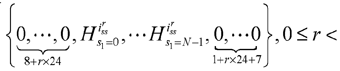
0,'K —0 tfflss 0 ···()
」 — u k5<r <10
8+rx24+l
第六例, 与第五例不同的是, 在本实施例中, 发送端例如是站点, 所以 应用于上行传输, 接收端例如是 AP。 通常来说, 上行数据传输受 AP调度, AP会先在下行帧中给出下一次或若干次的上行资源指示。 假设上行资源指示 中设定本次上行传输第 Γ个 RB 带宽上总共发射的空间流数为 , 其中 = 0,1,·.·9。 共有 NJ个用户共用这个 RB。 Λζ ^为第 r个 RB带宽上第 u个用 户发射的空间流数, Μ = 0,1 ·· -1。 其余步骤与第五例相同。
关于在接收端进行信道估计的过程, 与第四例不同的是, 在本实施例中, 在步骤 203中, 根据指示信息确定 LTF数量 Μ及接收端对应的空间流。 接收 端对应的空间流具体为第 个 RB带宽上每个用户分别发射的空间流 。 指 示信息具体为从 AP发送的上行资源指示中获得的。 其余步骤与第五例相同。
基于同一发明构思, 本申请一实施例中还提供一种发送数据的装置, 图 4 所示的发送数据的装置涉及到的术语的含义以及具体实现,可以参考前述图 2 和图 3以及实施例的相关描述。
请参考图 4所示, 该发送数据的装置包括: 处理单元 301, 用于对第一时 域序列进行傅里叶变换得到第一频域序列; 第一时域序列为具有自相关性质 的序列; 根据系统传输信道的最大多径时延、 信道的带宽和子载波数 , 确定单个符号能够支持的最大空间流数; 根据空间流总数, 在参数配置表中 确定出每个空间流所对应的循环移位参数; 循环移位参数表征第一时域序列 的时序移位值; 根据第一频域序列、 最大空间流数和循环移位参数获得长训 练字段 LTF; 发送单元 302, 用于将 LTF和指示信息发送给各接收端, 指示信息
包括分配给各接收端的空间流的编号。
可选的, 处理单元 301还用于根据空间流总数和最大空间流数确定符号数 量。
可选的, 处理单元 301还用于: 根据空间流总数, 在参数配置表中确定出 每个空间流所对应的正交映射矩阵; 根据第一频域序列、 最大空间流数、 循 环移位参数和正交映射矩阵获得 LTF。
结合以上各实施例, 参数配置表包括在空间流总数下, 每个空间流与循 环移位参数之间的对应关系。
可选的, 处理单元 301 具体用于: 根据第一频域序列、 最大空间流数、 循环移位参数和正交映射矩阵获得每个空间流的第二频域序列; 通过对第二 频域序列进行反傅里叶变换, 得到每个空间流对应的第二时域序列; 通过将 每个空间流对应的第二时域序列求和, 得到 LTF。
结合以上各实施例, 处理单元 301具体用于: 用子载波数 N 除以带宽, 得到正交频分复用 OFDM符号的离散反傅里叶变换 IDFT周期;用 IDFT周期 除以最大多径时延得到单个符号能够支持的最大空间流数。
结合以上各实施例, 第一时域序列的长度为 N, N 为信道的连续可用子 载波数或一个资源块所包含的子载波数; 第一频域序列的长度为子载波数
M
" FFT。
前述图 2 实施例中的发送数据的方法中的各种变化方式和具体实例同样 适用于本实施例的发送数据的装置, 通过前述对发送数据的方法的详细描述, 本领域技术人员可以清楚的知道本实施例中发送数据的装置的实施方法, 所 以为了说明书的简洁, 在此不再详述。
基于同一发明构思, 本实施例还提供一种发送端设备, 例如为无线局域 网接入点或站点, 图 5所示的发送端设备涉及到的术语的含义以及具体实现, 可以参考前述图 2和图 3以及实施例的相关描述。
请参考图 5所示, 为本实施例中发送端设备的硬件示意图。 该发送端设备
包括: 处理器 401, 用于对第一时域序列进行傅里叶变换得到第一频域序列; 第一时域序列为具有自相关性质的序列; 根据系统传输信道的最大多径时延、 信道的带宽和子载波数 确定单个符号能够支持的最大空间流数; 根据 空间流总数, 在参数配置表中确定出每个空间流所对应的循环移位参数; 循 环移位参数表征第一时域序列的时序移位值; 根据第一频域序列、 最大空间 流数和循环移位参数获得长训练字段 LTF; 发送器 402,用于将 LTF和指示信息 发送给各接收端, 指示信息包括分配给各接收端的空间流的编号。
可选的, 处理器 401还用于根据空间流总数和最大空间流数确定符号数 量。
可选的, 处理器 401还用于: 根据空间流总数, 在参数配置表中确定出每 个空间流所对应的正交映射矩阵; 根据第一频域序列、 最大空间流数、 循环 移位参数和正交映射矩阵获得 LTF。
结合以上各实施例, 参数配置表包括在空间流总数下, 每个空间流与循 环移位参数之间的对应关系。
可选的, 处理器 401 具体用于: 根据第一频域序列、 最大空间流数、 循 环移位参数和正交映射矩阵获得每个空间流的第二频域序列; 通过对第二频 域序列进行反傅里叶变换, 得到每个空间流对应的第二时域序列; 通过将每 个空间流对应的第二时域序列求和, 得到 LTF。
结合以上各实施例, 处理器 401 具体用于: 用子载波数 N^除以带宽, 得到正交频分复用 OFDM符号的离散反傅里叶变换 IDFT周期;用 IDFT周期 除以最大多径时延得到单个符号能够支持的最大空间流数。
结合以上各实施例, 第一时域序列的长度为 N, N 为信道的连续可用子 载波数或一个资源块所包含的子载波数; 第一频域序列的长度为子载波数
M
" FFT °
进一步, 在图 5中, 总线架构 (用总线 400来代表), 总线 400可以包括 任意数量的互联的总线和桥, 总线 400将包括由处理器 401代表的一个或多
个处理器和存储器 404代表的存储器的各种电路链接在一起。 总线 400还可 以将诸如外围设备、 稳压器和功率管理电路等之类的各种其他电路链接在一 起, 这些都是本领域所公知的, 因此, 本文不再对其进行进一步描述。 总线 接口 405在总线 400和接收器 403和发送器 402之间提供接口。 接收器 403 和发送器 402 可以是同一个元件, 即收发机, 提供用于在传输介质上与各种 其他装置通信的单元。
取决于接收端设备的性质, 还可以提供用户接口, 例如小键盘、 显示器、 扬声器、 麦克风、 操纵杆。
处理器 401 负责管理总线 400和通常的处理, 而存储器 404可以被用于 存储处理器 401 在执行操作时所使用的数据。 进一步, 参数配置表存储在存 储器 404中。 适用于本实施例的发送端设备, 通过前述对发送数据的方法的详细描述, 本 领域技术人员可以清楚的知道本实施例中发送端设备的实施方法, 所以为了 说明书的简洁, 在此不再详述。
基于同一发明构思, 本实施例提供一种信道估计装置, 请参考图 6所示, 该信道估计装置包括: 接收单元 501 , 用于接收发送端发送的长训练字段 LTF 和指示信息, 指示信息包括分配给接收端的空间流的编号; 处理单元 502, 用 于获得空间流总数和单个符号能够支持的最大空间流数; 根据空间流总数及 空间流的编号, 在参数配置表中确定出空间流对应的循环移位参数; 循环移 位参数表征第一时域序列的时序移位值; 其中, 第一时域序列为具有自相关 性质的序列; 根据循环移位参数、 最大空间流数、 第一时域序列、 第一时域 序列的长度 N、 空间流的编号和接收到的 LTF , 确定空间流对应的频域信道 估计值。
可选的, 处理单元 502还用于: 根据空间流总数及空间流的编号, 在参 数配置表中确定出空间流对应的正交映射矩阵; 根据循环移位参数、 最大空 间流数、 第一时域序列、 第一时域序列的长度 N、 空间流的编号、 正交映射
矩阵和接收到的 LTF, 确定空间流对应的频域信道估计值。
可选的, 处理单元 502用于: 根据循环移位参数、 单个符号能够支持的 最大空间流数和第一时域序列的长度 N确定窗函数; 根据空间流的编号和正 交映射矩阵对接收到的 LTF进行合并; 根据合并后的 LTF, 获得第二估计时 域序列; 通过对第二估计时域序列进行傅里叶变换, 获得第一估计频域序列; 从第一频域序列提取出与接收端对应的连续可用子载波的位置和数量相对应 的至少一个第二估计频域序列; 对至少一个第二估计频域序列进行反傅里叶 变换, 获得至少一个第三估计时域序列; 利用窗函数对至少一个第三时域序 列和第一时域序列进行处理, 获得至少一个第四估计时域序列; 通过对至少 一个第四估计时域序列分别进行傅里叶变换, 获得空间流对应的频域信道估 计值。
结合以上各实施例, 第一时域序列的长度 N具体为信道的连续可用子载 波数或一个资源块所包含的子载波数为长度N。
结合以上各实施例, 参数配置表包括在空间流总数下, 每个空间流与循 环移位参数之间的对应关系。
前述图 3 实施例中的信道估计方法中的各种变化方式和具体实例同样适 用于本实施例的信道估计装置, 通过前述对信道估计方法的详细描述, 本领 域技术人员可以清楚的知道本实施例中信道估计装置的实施方法, 所以为了 说明书的简洁, 在此不再详述。
基于同一发明构思, 本实施例提供一种接收端设备, 请参考图 7 所示, 为本实施例中接收端设备的硬件示意图。 该接收端设备包括: 接收器 601 , 用 于接收发送端发送的长训练字段 LTF和指示信息, 指示信息包括分配给接收 端的空间流的编号; 处理器 602, 用于获得空间流总数和单个符号能够支持的 最大空间流数; 根据空间流总数及空间流的编号, 在参数配置表中确定出空 间流对应的循环移位参数; 循环移位参数表征第一时域序列的时序移位值; 其中, 第一时域序列为具有自相关性质的序列; 根据循环移位参数、 最大空 间流数、 第一时域序列、 第一时域序列的长度 N、 空间流的编号和接收到的
LTF, 确定空间流对应的频域信道估计值。
可选的, 处理器 602还用于: 根据空间流总数及空间流的编号, 在参数 配置表中确定出空间流对应的正交映射矩阵; 根据循环移位参数、 最大空间 流数、 第一时域序列、 第一时域序列的长度 N、 空间流的编号、 正交映射矩 阵和接收到的 LTF, 确定空间流对应的频域信道估计值。
可选的, 处理器 602用于: 才艮据循环移位参数、 单个符号能够支持的最 大空间流数和第一时域序列的长度 N确定窗函数; 根据空间流的编号和正交 映射矩阵对接收到的 LTF进行合并; 根据合并后的 LTF, 获得第二估计时域 序列; 通过对第二估计时域序列进行傅里叶变换, 获得第一估计频域序列; 从第一频域序列提取出与接收端对应的连续可用子载波的位置和数量相对应 的至少一个第二估计频域序列; 对至少一个第二估计频域序列进行反傅里叶 变换, 获得至少一个第三估计时域序列; 利用窗函数对至少一个第三时域序 列和第一时域序列进行处理, 获得至少一个第四估计时域序列; 通过对至少 一个第四估计时域序列分别进行傅里叶变换, 获得空间流对应的频域信道估 计值。
结合以上各实施例, 第一时域序列的长度 N具体为信道的连续可用子载 波数或一个资源块所包含的子载波数为长度^。
结合以上各实施例, 参数配置表包括在空间流总数下, 每个空间流与循 环移位参数之间的对应关系。
进一步, 在图 7中, 总线架构 (用总线 600来代表), 总线 600可以包括 任意数量的互联的总线和桥, 总线 600将包括由处理器 602代表的一个或多 个处理器和存储器 604代表的存储器的各种电路链接在一起。 总线 600还可 以将诸如外围设备、 稳压器和功率管理电路等之类的各种其他电路链接在一 起, 这些都是本领域所公知的, 因此, 本文不再对其进行进一步描述。 总线 接口 605在总线 600和接收器 601和发送器 603之间提供接口。 接收器 601 和发送器 603 可以是同一个元件, 即收发机, 提供用于在传输介质上与各种 其他装置通信的单元。
取决于接收端设备的性质, 还可以提供用户接口, 例如小键盘、 显示器、 扬声器、 麦克风、 操纵杆。
处理器 602负责管理总线 600和通常的处理, 而存储器 604可以被用于 存储处理器 602在执行操作时所使用的数据。 例如, 参数配置表存储在存储 器 604中。
前述图 3 实施例中的信道估计方法中的各种变化方式和具体实例同样适 用于本实施例的接收端设备, 通过前述对信道估计方法的详细描述, 本领域 技术人员可以清楚的知道本实施例中接收端设备的实施方法, 所以为了说明 书的简洁, 在此不再详述。
本申请实施例中提供的一个或多个技术方案, 至少具有如下技术效果或 优点:
在本申请实施例中, 对具有自相关性质的第一时域序列进行傅里叶变换 得到第一频域序列; 根据信道的最大多径时延、 信道的带宽和子载波数, 确 定单个符号能够支持的最大空间流数; 然后根据空间流总数, 在参数配置表 中确定出每个空间流所对应的循环移位参数, 其中, 循环移位参数表征第一 时域序列的时序移位值; 然后根据第一频域序列、 最大空间流数和循环移位 参数获得 LTF。 因此, 在本实施例中, 采用具备自相关性质的序列作为 LTF 使用的序列, 然后通过不同的循环移位参数来区分多空间流场景下每个空间 流所使用的符号, 至少只要移一次位, 就可以以此区分开两个空间流, 所以 对于 8空间流而言, 每个空间流最多只要发送 4个符号。 因此, 通过本实施 例中的方法, 每个空间流需发送的符号数少于现有技术中所发送的符号数, 即可以实现信道估计, 从而降低了系统开销, 尤其降低了较多子载波数, 较 长保护间隔的参数配置下的系统开销。
本领域内的技术人员应明白, 本申请的实施例可提供为方法、 系统、 或 计算机程序产品。 因此, 本申请可釆用完全硬件实施例、 完全软件实施例、 或结合软件和硬件方面的实施例的形式。 而且, 本申请可采用在一个或多个 其中包含有计算机可用程序代码的计算机可用存储介质 (包括但不限于磁盘
存储器和光学存储器等 )上实施的计算机程序产品的形式。
本申请是参照根据本申请实施例的方法、 设备(系统)、 和计算机程序产 品的流程图和 /或方框图来描述的。 应理解可由计算机程序指令实现流程图 和 /或方框图中的每一流程和 /或方框、 以及流程图和 /或方框图中的流程 和 /或方框的结合。 可提供这些计算机程序指令到通用计算机、 专用计算机、 嵌入式处理机或其他可编程数据处理设备的处理器以产生一个机器, 使得通 过计算机或其他可编程数据处理设备的处理器执行的指令产生用于实现在流 程图一个流程或多个流程和 /或方框图一个方框或多个方框中指定的功能的 装置。
这些计算机程序指令也可存储在能引导计算机或其他可编程数据处理设 备以特定方式工作的计算机可读存储器中, 使得存储在该计算机可读存储器 中的指令产生包括指令装置的制造品, 该指令装置实现在流程图一个流程或 多个流程和 /或方框图一个方框或多个方框中指定的功能。
这些计算机程序指令也可装载到计算机或其他可编程数据处理设备上, 使得在计算机或其他可编程设备上执行一系列操作步骤以产生计算机实现的 处理, 从而在计算机或其他可编程设备上执行的指令提供用于实现在流程图 一个流程或多个流程和 /或方框图一个方框或多个方框中指定的功能的步 骤。
显然 , 本领域的技术人员可以对本申请进行各种改动和变型而不脱离本 申请的精神和范围。 这样, 倘若本申请的这些修改和变型属于本申请权利要 求及其等同技术的范围之内, 则本申请也意图包含这些改动和变型在内。
Claims
1、 一种发送数据的方法, 其特征在于, 包括:
对第一时域序列进行傅里叶变换得到第一频域序列; 所述第一时域序列 为具有自相关性质的序列;
根据系统传输信道的最大多径时延、 所述信道的带宽和子载波数 N , 确定单个符号能够支持的最大空间流数;
根据空间流总数, 在参数配置表中确定出每个空间流所对应的循环移位 参数; 所述循环移位参数表征所述第一时域序列的时序移位值;
根据所述第一频域序列、 所述最大空间流数和所述循环移位参数获得长 训练字段 LTF;
将所述 LTF和指示信息发送给各接收端, 所述指示信息包括分配给各接 收端的空间流的编号。
2、 如权利要求 1所述的方法, 其特征在于, 所述指示信息还包括所述各 接收端的符号数据, 通过以下步骤获得所述符号数量:
根据所述空间流总数和所述最大空间流数确定所述符号数量。
3、 如权利要求 1或 2所述的方法, 其特征在于, 所述方法还包括: 根据所述空间流总数, 在所述参数配置表中确定出每个空间流所对应的 正交映射矩阵;
根据所述第一频域序列、 所述最大空间流数和所述循环移位参数获得长 训练字段 LTF, 包括:
根据所述第一频域序列、 所述最大空间流数、 所述循环移位参数和所述 正交映射矩阵获得所述 LTF。
4、 如权利要求 1-3任一项所述的方法, 其特征在于, 所述参数配置表包 括在所述空间流总数下, 每个空间流与所述循环移位参数之间的对应关系。
5、如权利要求 4所述的方法, 其特征在于, 所述根据所述第一频域序列、 所述最大空间流数、 所述循环移位参数和所述正交映射矩阵获得所述 LTF,
包括:
根据所述第一频域序列、 所述最大空间流数、 所述循环移位参数和所述 正交映射矩阵获得每个空间流的第二频域序列;
通过对所述第二频域序列进行反傅里叶变换, 得到所述每个空间流对应 的第二时域序列;
通过将所述每个空间流对应的第二时域序列求和, 得到所述 LTF。
6、 如权利要求 1-5任一项所述的方法, 其特征在于, 所述根据所述信道 的最大多径时延、 所述信道的带宽和子载波数 NFiT, 确定单个符号能够支持 的最大空间流数, 包括:
用所述子载波数 NFiT除以所述带宽, 得到正交频分复用 OFDM符号的离 散反傅里叶变换 IDFT周期;
用所述 IDFT 周期除以所述最大多径时延得到所述单个符号能够支持的 最大空间流数。
7、 如权利要求 1-6任一项所述的方法, 其特征在于, 所述第一时域序列 的长度为 Ν, Ν 为所述信道的连续可用子载波数或一个资源块所包含的子载 波数;
所述第一频域序列的长度为所述子载波数 NFiT。
8、 一种信道估计方法, 其特征在于, 包括:
接收发送端发送的长训练字段 LTF和指示信息, 所述指示信息包括分配 给接收端的空间流的编号;
获得空间流总数和单个符号能够支持的最大空间流数;
根据所述空间流总数及所述空间流的编号, 在参数配置表中确定出所述 空间流对应的循环移位参数; 所述循环移位参数表征第一时域序列的时序移 位值; 其中, 所述第一时域序列为具有自相关性质的序列;
根据所述循环移位参数、 所述最大空间流数、 所述第一时域序列、 所述 第一时域序列的长度 Ν、 所述空间流的编号和接收到的 LTF, 确定所述空间
流对应的频域信道估计值。
9、 如权利要求 8所述的方法, 其特征在于, 所述方法还包括:
根据所述空间流总数及所述空间流的编号, 在所述参数配置表中确定出 所述空间流对应的正交映射矩阵;
根据所述循环移位参数、 所述最大空间流数、 所述第一时域序列、 所述 第一时域序列的长度 N、 所述空间流的编号和接收到的 LTF, 确定所述空间 流对应的频域信道估计值, 包括:
根据所述循环移位参数、 所述最大空间流数、 所述第一时域序列、 所述 第一时域序列的长度 N、 所述空间流的编号、 所述正交映射矩阵和接收到的 LTF , 确定所述空间流对应的频域信道估计值。
10、 如权利要求 9 所述的方法, 其特征在于, 所述通过根据所述循环移 位参数、 所述单个符号能够支持的最大空间流数、 所述第一时域序列、 所述 第一时域序列的长度 N、 所述正交映射矩阵和接收到的 LTF, 确定所述空间 流对应的频域信道估计值, 包括:
根据所述循环移位参数、 所述单个符号能够支持的最大空间流数和所述 第一时域序列的长度 N确定窗函数;
根据所述空间流的编号和所述正交映射矩阵对所述接收到的 LTF进行合 并;
根据合并后的 LTF , 获得第二估计时域序列;
通过对所述第二估计时域序列进行傅里叶变换, 获得第一估计频域序列; 从所述第一频域序列提取出与接收端对应的连续可用子载波的位置和数 量相对应的至少一个第二估计频域序列;
对所述至少一个第二估计频域序列进行反傅里叶变换, 获得至少一个第 三估计时域序列;
利用所述窗函数对所述至少一个第三时域序列和所述第一时域序列进行 处理, 获得至少一个第四估计时域序列;
通过对所述至少一个第四估计时域序列分别进行傅里叶变换, 获得所述
空间流对应的频域信道估计值。
11、 如权利要求 8-10任一项所述的方法, 其特征在于, 所述第一时域序 列的长度 N具体为所述信道的连续可用子载波数或一个资源块所包含的子载 波数为所述长度>^。
12、 如权利要求 8-11任一项所述的方法, 其特征在于, 所述参数配置表 包括在所述空间流总数下, 每个空间流与所述循环移位参数之间的对应关系。
13、 一种发送数据的装置, 其特征在于, 包括:
处理单元, 用于对第一时域序列进行傅里叶变换得到第一频域序列; 所 述第一时域序列为具有自相关性质的序列; 根据系统传输信道的最大多径时 延、 所述信道的带宽和子载波数 确定单个符号能够支持的最大空间流 数; 根据空间流总数, 在参数配置表中确定出每个空间流所对应的循环移位 参数; 所述循环移位参数表征所述第一时域序列的时序移位值; 根据所述第 一频域序列、 所述最大空间流数和所述循环移位参数获得长训练字段 LTF; 发送单元, 用于将所述 LTF和指示信息发送给各接收端, 所述指示信息包 括分配给各接收端的空间流的编号。
14、 如权利要求 13所述的装置, 其特征在于, 所述处理单元还用于根据 所述空间流总数和所述最大空间流数确定所述符号数量。
15、 如权利要求 13或 14所述的装置, 其特征在于, 所述处理单元还用于: 根据所述空间流总数, 在所述参数配置表中确定出每个空间流所对应的正交 映射矩阵; 根据所述第一频域序列、 所述最大空间流数、 所述循环移位参数 和所述正交映射矩阵获得所述 LTF。
16、 如权利要求 13-15任一项所述的装置, 其特征在于, 所述参数配置表 包括在所述空间流总数下, 每个空间流与所述循环移位参数之间的对应关系。
17、 如权利要求 16所述的装置, 其特征在于, 所述处理单元具体用于: 根据所述第一频域序列、 所述最大空间流数、 所述循环移位参数和所述正交 映射矩阵获得每个空间流的第二频域序列; 通过对所述第二频域序列进行反
傅里叶变换, 得到所述每个空间流对应的第二时域序列; 通过将所述每个空 间流对应的第二时域序列求和, 得到所述 LTF。
18、 如权利要求 13-17任一项所述的装置, 其特征在于, 所述处理单元具 体用于: 用所述子载波数 N^除以所述带宽, 得到正交频分复用 OFDM符号 的离散反傅里叶变换 IDFT周期; 用所述 IDFT周期除以所述最大多径时延得 到所述单个符号能够支持的最大空间流数。
19、 如权利要求 13-18任一项所述的装置, 其特征在于, 所述第一时域序 列的长度为 N, N 为所述信道的连续可用子载波数或一个资源块所包含的子 载波数; 所述第一频域序列的长度为所述子载波数 N 。
20、 一种信道估计装置, 其特征在于, 包括:
接收单元, 用于接收发送端发送的长训练字段 LTF和指示信息, 所述指 示信息包括分配给接收端的空间流的编号;
处理单元, 用于获得空间流总数和单个符号能够支持的最大空间流数; 根据所述空间流总数及所述空间流的编号, 在参数配置表中确定出所述空间 流对应的循环移位参数; 所述循环移位参数表征第一时域序列的时序移位值; 其中, 所述第一时域序列为具有自相关性质的序列; 根据所述循环移位参数、 所述最大空间流数、 所述第一时域序列、 所述第一时域序列的长度 Ν、 所述 空间流的编号和接收到的 LTF, 确定所述空间流对应的频域信道估计值。
21、 如权利要求 20所述的装置, 其特征在于, 所述处理单元还用于: 根 据所述空间流总数及所述空间流的编号, 在所述参数配置表中确定出所述空 间流对应的正交映射矩阵; 根据所述循环移位参数、 所述最大空间流数、 所 述第一时域序列、 所述第一时域序列的长度 Ν、 所述空间流的编号、 所述正 交映射矩阵和接收到的 LTF , 确定所述空间流对应的频域信道估计值。
22、 如权利要求 21所述的装置, 其特征在于, 所述处理单元用于: 根据 所述循环移位参数、 所述单个符号能够支持的最大空间流数和所述第一时域 序列的长度 Ν确定窗函数; 根据所述空间流的编号和所述正交映射矩阵对所
述接收到的 LTF进行合并; 根据合并后的 LTF , 获得第二估计时域序列; 通 过对所述第二估计时域序列进行傅里叶变换, 获得第一估计频域序列; 从所 述第一频域序列提取出与接收端对应的连续可用子载波的位置和数量相对应 的至少一个第二估计频域序列; 对所述至少一个第二估计频域序列进行反傅 里叶变换, 获得至少一个第三估计时域序列; 利用所述窗函数对所述至少一 个第三时域序列和所述第一时域序列进行处理, 获得至少一个第四估计时域 序列; 通过对所述至少一个第四估计时域序列分别进行傅里叶变换, 获得所 述空间流对应的频域信道估计值。
23、 如权利要求 20-22任一项所述的装置, 其特征在于, 所述第一时域序 列的长度 N具体为所述信道的连续可用子载波数或一个资源块所包含的子载 波数为所述长度N。
24、 如权利要求 20-23任一项所述的装置, 其特征在于, 所述参数配置表 包括在所述空间流总数下 , 每个空间流与所述循环移位参数之间的对应关系。
25、 一种发送端设备, 其特征在于, 包括:
处理器, 用于对第一时域序列进行傅里叶变换得到第一频域序列; 所述 第一时域序列为具有自相关性质的序列; 根据系统传输信道的最大多径时延、 所述信道的带宽和子载波数 NFiT , 确定单个符号能够支持的最大空间流数; 根据空间流总数, 在参数配置表中确定出每个空间流所对应的循环移位参数; 所述循环移位参数表征所述第一时域序列的时序移位值; 根据所述第一频域 序列、 所述最大空间流数和所述循环移位参数获得长训练字段 LTF;
发送器, 用于将所述 LTF和指示信息发送给各接收端, 所述指示信息包括 分配给各接收端的空间流的编号。
26、 如权利要求 25所述的设备, 其特征在于, 所述处理器还用于根据所 述空间流总数和所述最大空间流数确定所述符号数量。
27、 如权利要求 25或 26所述的设备, 其特征在于, 所述处理器还用于: 根据所述空间流总数, 在所述参数配置表中确定出每个空间流所对应的正交
映射矩阵; 根据所述第一频域序列、 所述最大空间流数、 所述循环移位参数 和所述正交映射矩阵获得所述 LTF。
28、 如权利要求 25-27任一项所述的设备, 其特征在于, 所述参数配置表 包括在所述空间流总数下, 每个空间流与所述循环移位参数之间的对应关系。
29、 如权利要求 28所述的设备, 其特征在于, 所述处理器具体用于: 根 据所述第一频域序列、 所述最大空间流数、 所述循环移位参数和所述正交映 射矩阵获得每个空间流的第二频域序列; 通过对所述第二频域序列进行反傅 里叶变换, 得到所述每个空间流对应的第二时域序列; 通过将所述每个空间 流对应的第二时域序列求和 , 得到所述 LTF。
30、 如权利要求 25-29任一项所述的设备, 其特征在于, 所述处理器具体 用于: 用所述子载波数 N 除以所述带宽, 得到正交频分复用 OFDM符号的 离散反傅里叶变换 IDFT周期; 用所述 IDFT周期除以所述最大多径时延得到 所述单个符号能够支持的最大空间流数。
31、 如权利要求 25-30任一项所述的设备, 其特征在于, 所述第一时域序 列的长度为 N, N 为所述信道的连续可用子载波数或一个资源块所包含的子 载波数; 所述第一频域序列的长度为所述子载波数 N 。
32、 如权利要求 25-31任一项所述的设备, 其特征在于, 所述发送端设备 为无线局域网接入点或站点。
33、 一种接收端设备, 其特征在于, 包括:
接收器, 用于接收发送端发送的长训练字段 LTF和指示信息, 所述指示 信息包括分配给接收端的空间流的编号;
处理器, 用于获得空间流总数和单个符号能够支持的最大空间流数; 根 据所述空间流总数及所述空间流的编号, 在参数配置表中确定出所述空间流 对应的循环移位参数; 所述循环移位参数表征第一时域序列的时序移位值; 其中, 所述第一时域序列为具有自相关性质的序列; 根据所述循环移位参数、 所述最大空间流数、 所述第一时域序列、 所述第一时域序列的长度 Ν、 所述
空间流的编号和接收到的 LTF, 确定所述空间流对应的频域信道估计值。
34、 如权利要求 33所述的设备, 其特征在于, 所述处理器还用于: 根据 所述空间流总数及所述空间流的编号, 在所述参数配置表中确定出所述空间 流对应的正交映射矩阵; 根据所述循环移位参数、 所述最大空间流数、 所述 第一时域序列、 所述第一时域序列的长度 N、 所述空间流的编号、 所述正交 映射矩阵和接收到的 LTF, 确定所述空间流对应的频域信道估计值。
35、 如权利要求 34所述的设备, 其特征在于, 所述处理器用于: 根据所 述循环移位参数、 所述单个符号能够支持的最大空间流数和所述第一时域序 列的长度 N确定窗函数; 根据所述空间流的编号和所述正交映射矩阵对所述 接收到的 LTF进行合并; 根据合并后的 LTF, 获得第二估计时域序列; 通过 对所述第二估计时域序列进行傅里叶变换, 获得第一估计频域序列; 从所述 第一频域序列提取出与接收端对应的连续可用子载波的位置和数量相对应的 至少一个第二估计频域序列; 对所述至少一个第二估计频域序列进行反傅里 叶变换, 获得至少一个第三估计时域序列; 利用所述窗函数对所述至少一个 第三时域序列和所述第一时域序列进行处理, 获得至少一个第四估计时域序 列; 通过对所述至少一个第四估计时域序列分别进行傅里叶变换, 获得所述 空间流对应的频域信道估计值。
36、 如权利要求 33-35任一项所述的设备, 其特征在于, 所述第一时域序 列的长度 N具体为所述信道的连续可用子载波数或一个资源块所包含的子载 波数为所述长度^^。
37、 如权利要求 33-36任一项所述的设备, 其特征在于, 所述参数配置表 包括在所述空间流总数下, 每个空间流与所述循环移位参数之间的对应关系。
38、 如权利要求 33-37任一项所述的设备, 其特征在于, 所述接收端设备 为站点或无线局域网接入点。
Priority Applications (4)
| Application Number | Priority Date | Filing Date | Title |
|---|---|---|---|
| EP14900355.0A EP3188392B1 (en) | 2014-08-30 | 2014-08-30 | Data transmitting method, channel estimation method and device |
| PCT/CN2014/085635 WO2016029482A1 (zh) | 2014-08-30 | 2014-08-30 | 一种发送数据的方法、信道估计方法及装置 |
| CN201480049657.5A CN105580302B (zh) | 2014-08-30 | 2014-08-30 | 一种发送数据的方法、信道估计方法及装置 |
| US15/443,360 US20170170933A1 (en) | 2014-08-30 | 2017-02-27 | Data sending method, channel estimation method, and apparatuses thereof |
Applications Claiming Priority (1)
| Application Number | Priority Date | Filing Date | Title |
|---|---|---|---|
| PCT/CN2014/085635 WO2016029482A1 (zh) | 2014-08-30 | 2014-08-30 | 一种发送数据的方法、信道估计方法及装置 |
Related Child Applications (1)
| Application Number | Title | Priority Date | Filing Date |
|---|---|---|---|
| US15/443,360 Continuation US20170170933A1 (en) | 2014-08-30 | 2017-02-27 | Data sending method, channel estimation method, and apparatuses thereof |
Publications (1)
| Publication Number | Publication Date |
|---|---|
| WO2016029482A1 true WO2016029482A1 (zh) | 2016-03-03 |
Family
ID=55398687
Family Applications (1)
| Application Number | Title | Priority Date | Filing Date |
|---|---|---|---|
| PCT/CN2014/085635 WO2016029482A1 (zh) | 2014-08-30 | 2014-08-30 | 一种发送数据的方法、信道估计方法及装置 |
Country Status (4)
| Country | Link |
|---|---|
| US (1) | US20170170933A1 (zh) |
| EP (1) | EP3188392B1 (zh) |
| CN (1) | CN105580302B (zh) |
| WO (1) | WO2016029482A1 (zh) |
Cited By (1)
| Publication number | Priority date | Publication date | Assignee | Title |
|---|---|---|---|---|
| CN111527783A (zh) * | 2018-05-11 | 2020-08-11 | Oppo广东移动通信有限公司 | 一种信息的指示方法及装置、计算机存储介质 |
Families Citing this family (7)
| Publication number | Priority date | Publication date | Assignee | Title |
|---|---|---|---|---|
| WO2016076511A1 (ko) * | 2014-11-16 | 2016-05-19 | 엘지전자 주식회사 | 무선랜 시스템에서 프레임 전송 방법 |
| CN112187690B (zh) * | 2019-07-02 | 2022-10-04 | 华为技术有限公司 | 符号处理的方法与装置 |
| CN115776426A (zh) | 2019-07-12 | 2023-03-10 | 成都华为技术有限公司 | 符号处理的方法与装置 |
| CN113395145B (zh) * | 2020-03-13 | 2023-09-22 | 华为技术有限公司 | 传输参数的确定方法及传输设备 |
| CN113765633B (zh) * | 2020-06-03 | 2023-04-18 | 华为技术有限公司 | 发送参考信号的方法和通信装置 |
| CN117176516A (zh) * | 2022-05-27 | 2023-12-05 | 中兴通讯股份有限公司 | 数据传输方法及装置、数据处理方法及装置、存储介质 |
| WO2024020813A1 (zh) * | 2022-07-26 | 2024-02-01 | 华为技术有限公司 | 参考信号传输方法及通信装置 |
Citations (4)
| Publication number | Priority date | Publication date | Assignee | Title |
|---|---|---|---|---|
| CN101277289A (zh) * | 2007-03-30 | 2008-10-01 | 华为技术有限公司 | 导频发射方法、发射装置 |
| CN102027724A (zh) * | 2008-03-31 | 2011-04-20 | 通用仪表公司 | 降低来自mimo发射机中的独立发射天线的衰减的ofdm信号的空间映射 |
| WO2012112973A1 (en) * | 2011-02-18 | 2012-08-23 | Qualcomm Incorporated | Data transmission coexistence using constant symbol duration within television white space channels |
| CN103138870A (zh) * | 2011-11-22 | 2013-06-05 | 华为技术有限公司 | 数据传输方法和数据传输装置 |
Family Cites Families (9)
| Publication number | Priority date | Publication date | Assignee | Title |
|---|---|---|---|---|
| DK1751890T3 (en) * | 2004-05-27 | 2017-06-12 | Qualcomm Inc | MODIFIED INTRODUCTION STRUCTURE FOR IEEE 802.11A EXTENSIONS TO ENABLE CO-EXISTENCE AND INTEROPERABILITY BETWEEN 802.11A DEVICES AND HIGHER DATARATES, MIMO OR OTHER EXTENDED DEVICES |
| JP4367422B2 (ja) * | 2006-02-14 | 2009-11-18 | ソニー株式会社 | 無線通信装置及び無線通信方法 |
| CN103812816B (zh) * | 2008-05-15 | 2017-04-26 | 马维尔国际贸易有限公司 | 有效的物理层前导格式 |
| US8218663B2 (en) * | 2008-07-29 | 2012-07-10 | Texas Instruments Incorporated | Reference signal resource allocation for single user MIMO |
| US9252862B2 (en) * | 2008-09-17 | 2016-02-02 | Qualcomm Incorporated | MIMO preamble for initial access with an unknown number of transmit antennas |
| MX2012003190A (es) * | 2009-12-10 | 2012-04-30 | Lg Electronics Inc | Metodo y aparato de transmision de señal de entrenamiento en un sistema de red de area local inalambrico. |
| EP3273619A1 (en) * | 2010-04-29 | 2018-01-24 | LG Electronics Inc. | Method and apparatus for transmitting data in very high throughput wireless local area network system |
| CN103548380B (zh) * | 2011-06-03 | 2017-04-05 | 松下电器(美国)知识产权公司 | 终端装置和响应信号发送方法 |
| US9439161B2 (en) * | 2013-07-17 | 2016-09-06 | Qualcomm Incorporated | Physical layer design for uplink (UL) multiuser multiple-input, multiple-output (MU-MIMO) in wireless local area network (WLAN) systems |
-
2014
- 2014-08-30 EP EP14900355.0A patent/EP3188392B1/en active Active
- 2014-08-30 WO PCT/CN2014/085635 patent/WO2016029482A1/zh active Application Filing
- 2014-08-30 CN CN201480049657.5A patent/CN105580302B/zh active Active
-
2017
- 2017-02-27 US US15/443,360 patent/US20170170933A1/en not_active Abandoned
Patent Citations (4)
| Publication number | Priority date | Publication date | Assignee | Title |
|---|---|---|---|---|
| CN101277289A (zh) * | 2007-03-30 | 2008-10-01 | 华为技术有限公司 | 导频发射方法、发射装置 |
| CN102027724A (zh) * | 2008-03-31 | 2011-04-20 | 通用仪表公司 | 降低来自mimo发射机中的独立发射天线的衰减的ofdm信号的空间映射 |
| WO2012112973A1 (en) * | 2011-02-18 | 2012-08-23 | Qualcomm Incorporated | Data transmission coexistence using constant symbol duration within television white space channels |
| CN103138870A (zh) * | 2011-11-22 | 2013-06-05 | 华为技术有限公司 | 数据传输方法和数据传输装置 |
Cited By (2)
| Publication number | Priority date | Publication date | Assignee | Title |
|---|---|---|---|---|
| CN111527783A (zh) * | 2018-05-11 | 2020-08-11 | Oppo广东移动通信有限公司 | 一种信息的指示方法及装置、计算机存储介质 |
| CN111527783B (zh) * | 2018-05-11 | 2023-08-11 | Oppo广东移动通信有限公司 | 一种信息的指示方法及装置、计算机存储介质 |
Also Published As
| Publication number | Publication date |
|---|---|
| EP3188392B1 (en) | 2018-11-14 |
| EP3188392A4 (en) | 2017-09-06 |
| US20170170933A1 (en) | 2017-06-15 |
| CN105580302B (zh) | 2019-04-19 |
| EP3188392A1 (en) | 2017-07-05 |
| CN105580302A (zh) | 2016-05-11 |
Similar Documents
| Publication | Publication Date | Title |
|---|---|---|
| WO2016029482A1 (zh) | 一种发送数据的方法、信道估计方法及装置 | |
| WO2020048280A1 (zh) | 一种传输数据的方法和装置 | |
| WO2018018417A1 (zh) | 信息传输方法和信息传输设备 | |
| RU2684640C1 (ru) | Способ и устройство передачи данных в беспроводной локальной сети | |
| CN109923841B (zh) | 一种参考信号配置方法、训练字段配置方法及装置 | |
| WO2014173292A1 (zh) | 一种导频信号的传输方法及设备 | |
| CN106576385B (zh) | 一种传输设备和数据帧的传输方法 | |
| WO2017128883A1 (zh) | 一种导频信号发送、信道估计方法及设备 | |
| WO2012130087A1 (zh) | 无线通信系统及其通信方法 | |
| WO2017193304A1 (zh) | 一种信号处理方法及发射机 | |
| CN107819716B (zh) | 一种基于频域的频偏补偿方法及设备 | |
| WO2017059719A1 (zh) | 传输数据的方法和设备 | |
| WO2022068684A1 (zh) | 相位噪声补偿方法及装置 | |
| CN109644520A (zh) | 资源映射的方法和通信设备 | |
| TWI733971B (zh) | 信號傳輸方法和設備 | |
| US11362780B2 (en) | DMRS sequence transmitting method, terminal device and network device | |
| CN110971556B (zh) | 一种无线通信系统的信号处理方法、终端设备及网络设备 | |
| TWI710235B (zh) | 傳輸數據的方法、信道估計的方法和裝置 | |
| AU2021323163B2 (en) | Method and apparatus for transmitting physical layer protocol data unit | |
| CN111294306B (zh) | 一种参考信号的传输方法及装置 | |
| TWI729165B (zh) | 信號傳輸方法和設備 | |
| US20180316536A1 (en) | Signal sending method, signal receiving method, terminal device, base station, and system | |
| CN114257484B (zh) | 一种符号应用方法及通信装置 | |
| JP2020512709A (ja) | 同期信号送信方法および同期信号送信装置 | |
| WO2020063930A1 (zh) | 一种参考信号的发送、接收方法及装置 |
Legal Events
| Date | Code | Title | Description |
|---|---|---|---|
| WWE | Wipo information: entry into national phase |
Ref document number: 201480049657.5 Country of ref document: CN |
|
| 121 | Ep: the epo has been informed by wipo that ep was designated in this application |
Ref document number: 14900355 Country of ref document: EP Kind code of ref document: A1 |
|
| REEP | Request for entry into the european phase |
Ref document number: 2014900355 Country of ref document: EP |
|
| WWE | Wipo information: entry into national phase |
Ref document number: 2014900355 Country of ref document: EP |
|
| NENP | Non-entry into the national phase |
Ref country code: DE |