WO2016021275A1 - Ultrasonic biopsy needle - Google Patents
Ultrasonic biopsy needle Download PDFInfo
- Publication number
- WO2016021275A1 WO2016021275A1 PCT/JP2015/064734 JP2015064734W WO2016021275A1 WO 2016021275 A1 WO2016021275 A1 WO 2016021275A1 JP 2015064734 W JP2015064734 W JP 2015064734W WO 2016021275 A1 WO2016021275 A1 WO 2016021275A1
- Authority
- WO
- WIPO (PCT)
- Prior art keywords
- sheath
- ultrasonic
- coil
- needle
- distal end
- Prior art date
Links
Images


Classifications
-
- A—HUMAN NECESSITIES
- A61—MEDICAL OR VETERINARY SCIENCE; HYGIENE
- A61B—DIAGNOSIS; SURGERY; IDENTIFICATION
- A61B8/00—Diagnosis using ultrasonic, sonic or infrasonic waves
- A61B8/08—Detecting organic movements or changes, e.g. tumours, cysts, swellings
- A61B8/0833—Detecting organic movements or changes, e.g. tumours, cysts, swellings involving detecting or locating foreign bodies or organic structures
- A61B8/0841—Detecting organic movements or changes, e.g. tumours, cysts, swellings involving detecting or locating foreign bodies or organic structures for locating instruments
-
- A—HUMAN NECESSITIES
- A61—MEDICAL OR VETERINARY SCIENCE; HYGIENE
- A61B—DIAGNOSIS; SURGERY; IDENTIFICATION
- A61B1/00—Instruments for performing medical examinations of the interior of cavities or tubes of the body by visual or photographical inspection, e.g. endoscopes; Illuminating arrangements therefor
- A61B1/00112—Connection or coupling means
- A61B1/00121—Connectors, fasteners and adapters, e.g. on the endoscope handle
-
- A—HUMAN NECESSITIES
- A61—MEDICAL OR VETERINARY SCIENCE; HYGIENE
- A61B—DIAGNOSIS; SURGERY; IDENTIFICATION
- A61B1/00—Instruments for performing medical examinations of the interior of cavities or tubes of the body by visual or photographical inspection, e.g. endoscopes; Illuminating arrangements therefor
- A61B1/00142—Instruments for performing medical examinations of the interior of cavities or tubes of the body by visual or photographical inspection, e.g. endoscopes; Illuminating arrangements therefor with means for preventing contamination, e.g. by using a sanitary sheath
-
- A—HUMAN NECESSITIES
- A61—MEDICAL OR VETERINARY SCIENCE; HYGIENE
- A61B—DIAGNOSIS; SURGERY; IDENTIFICATION
- A61B1/00—Instruments for performing medical examinations of the interior of cavities or tubes of the body by visual or photographical inspection, e.g. endoscopes; Illuminating arrangements therefor
- A61B1/012—Instruments for performing medical examinations of the interior of cavities or tubes of the body by visual or photographical inspection, e.g. endoscopes; Illuminating arrangements therefor characterised by internal passages or accessories therefor
- A61B1/018—Instruments for performing medical examinations of the interior of cavities or tubes of the body by visual or photographical inspection, e.g. endoscopes; Illuminating arrangements therefor characterised by internal passages or accessories therefor for receiving instruments
-
- A—HUMAN NECESSITIES
- A61—MEDICAL OR VETERINARY SCIENCE; HYGIENE
- A61B—DIAGNOSIS; SURGERY; IDENTIFICATION
- A61B1/00—Instruments for performing medical examinations of the interior of cavities or tubes of the body by visual or photographical inspection, e.g. endoscopes; Illuminating arrangements therefor
- A61B1/267—Instruments for performing medical examinations of the interior of cavities or tubes of the body by visual or photographical inspection, e.g. endoscopes; Illuminating arrangements therefor for the respiratory tract, e.g. laryngoscopes, bronchoscopes
- A61B1/2676—Bronchoscopes
-
- A—HUMAN NECESSITIES
- A61—MEDICAL OR VETERINARY SCIENCE; HYGIENE
- A61B—DIAGNOSIS; SURGERY; IDENTIFICATION
- A61B10/00—Other methods or instruments for diagnosis, e.g. instruments for taking a cell sample, for biopsy, for vaccination diagnosis; Sex determination; Ovulation-period determination; Throat striking implements
- A61B10/02—Instruments for taking cell samples or for biopsy
- A61B10/04—Endoscopic instruments
-
- A—HUMAN NECESSITIES
- A61—MEDICAL OR VETERINARY SCIENCE; HYGIENE
- A61B—DIAGNOSIS; SURGERY; IDENTIFICATION
- A61B8/00—Diagnosis using ultrasonic, sonic or infrasonic waves
- A61B8/12—Diagnosis using ultrasonic, sonic or infrasonic waves in body cavities or body tracts, e.g. by using catheters
-
- A—HUMAN NECESSITIES
- A61—MEDICAL OR VETERINARY SCIENCE; HYGIENE
- A61B—DIAGNOSIS; SURGERY; IDENTIFICATION
- A61B1/00—Instruments for performing medical examinations of the interior of cavities or tubes of the body by visual or photographical inspection, e.g. endoscopes; Illuminating arrangements therefor
- A61B1/00112—Connection or coupling means
- A61B1/00121—Connectors, fasteners and adapters, e.g. on the endoscope handle
- A61B1/00128—Connectors, fasteners and adapters, e.g. on the endoscope handle mechanical, e.g. for tubes or pipes
-
- A—HUMAN NECESSITIES
- A61—MEDICAL OR VETERINARY SCIENCE; HYGIENE
- A61B—DIAGNOSIS; SURGERY; IDENTIFICATION
- A61B1/00—Instruments for performing medical examinations of the interior of cavities or tubes of the body by visual or photographical inspection, e.g. endoscopes; Illuminating arrangements therefor
- A61B1/005—Flexible endoscopes
- A61B1/0051—Flexible endoscopes with controlled bending of insertion part
-
- A—HUMAN NECESSITIES
- A61—MEDICAL OR VETERINARY SCIENCE; HYGIENE
- A61B—DIAGNOSIS; SURGERY; IDENTIFICATION
- A61B1/00—Instruments for performing medical examinations of the interior of cavities or tubes of the body by visual or photographical inspection, e.g. endoscopes; Illuminating arrangements therefor
- A61B1/273—Instruments for performing medical examinations of the interior of cavities or tubes of the body by visual or photographical inspection, e.g. endoscopes; Illuminating arrangements therefor for the upper alimentary canal, e.g. oesophagoscopes, gastroscopes
-
- A—HUMAN NECESSITIES
- A61—MEDICAL OR VETERINARY SCIENCE; HYGIENE
- A61B—DIAGNOSIS; SURGERY; IDENTIFICATION
- A61B10/00—Other methods or instruments for diagnosis, e.g. instruments for taking a cell sample, for biopsy, for vaccination diagnosis; Sex determination; Ovulation-period determination; Throat striking implements
- A61B10/02—Instruments for taking cell samples or for biopsy
- A61B10/04—Endoscopic instruments
- A61B2010/045—Needles
Definitions
- the present invention relates to a biopsy needle used with an ultrasonic endoscope.
- an inspection method called biopsy in which a small amount of body tissue is collected and observed with a microscope, is known.
- tissue When collecting deep tissue such as organs, it is difficult to observe with an optical endoscope, so an ultrasonic tomographic image of the organ is obtained with an ultrasonic endoscope, etc.
- a tissue may be collected by inserting a biopsy needle.
- it is necessary to ensure that the ultrasonic transducer of the ultrasonic endoscope is in contact with the target tissue.
- Patent Document 1 discloses a puncture needle that can be used with an ultrasonic endoscope.
- Patent Document 2 discloses a combination of a resin and a metal blade in order to reduce the flexibility and the expansion / contraction rate of the tube through which the puncture needle is inserted.
- the respiratory endoscope has a smaller diameter than the digestive endoscope. For this reason, the amount of bending force of the bending portion that is actively bent in the respiratory endoscope is weaker than that of the bending portion of the digestive endoscope.
- the sheath of the biopsy needle applied to the respiratory endoscope is required to be flexible so that the bending ability of the respiratory endoscope does not decrease when the biopsy needle is inserted into the respiratory endoscope.
- a highly flexible sheath is generally rich in stretchability, it is particularly difficult to reduce the extension of the sheath and improve the flexibility of the sheath. Difficult in ultrasonic biopsy needles applied to.
- the sheath projects from the distal end of the endoscope by the stretched amount, and the projecting sheath pushes the tissue.
- the ultrasonic image becomes unclear because the distance between the tissue and the ultrasonic transducer is separated.
- the present invention has been made in view of the above-described problems, and an object of the present invention is to achieve both the suppression of the extension of the sheath accompanying the advancement and retraction of the needle tube and the improvement of the flexibility of the sheath.
- an ultrasonic biopsy needle is connected to a sheath that is inserted into a channel of an ultrasonic endoscope, a needle tube that is inserted into the sheath so as to be able to advance and retract, and a proximal end of the sheath.
- an operation unit for advancing and retracting the needle tube, and the sheath is configured such that the distal end of the sheath is positioned within the field of view of the optical imaging mechanism of the ultrasound endoscope.
- An extension suppressing portion located on the distal end side of the base end of the curved portion of the mirror, the extension suppressing portion is made of a metal coil, and the ratio of the outer diameter of the coil to the inner diameter of the channel is 1.0: It is in the range of 0.84 to 1.0: 0.96, the initial tension of the coil is 2.0 [N] or more, and suppresses the elongation of the sheath accompanying the advancement and retraction of the needle tube.
- the sheath in the ultrasonic biopsy needle according to the first aspect, may be formed from the coil over the entire length of the sheath.
- the coil may include a metal strand and a resin coating that covers the metal strand.
- the thickness of the resin coating may be not less than 0.15 mm and not more than 0.2 mm.
- the inner diameter of the channel may be 2.0 mm or more and 2.2 mm or less
- a slope portion may be formed with a fixed angle for causing the ultrasonic biopsy needle to protrude obliquely with respect to the transducer of the ultrasonic endoscope, and the maximum movement amount of the needle tube relative to the sheath is:
- the length may be 5% or more of the total length of the sheath.
- the ultrasonic biopsy needle According to the ultrasonic biopsy needle according to each of the above aspects, it is possible to achieve both suppression of sheath elongation accompanying the advancement and retraction of the needle tube and improvement of the flexibility of the sheath.
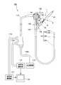
- FIG. 1 is an overall view of a biopsy system including an ultrasonic biopsy needle according to an embodiment of the present invention. It is sectional drawing of the front-end
- FIG. 1 is a diagram showing a schematic configuration of a biopsy system 150 of the present embodiment provided with a biopsy needle 1 and an ultrasonic endoscope 100.
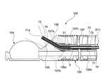
- FIG. 2 is a cross-sectional view of the distal end portion of the ultrasonic endoscope 100 that is an endoscope of the biopsy system 150.
- the ultrasonic biopsy needle 1 (hereinafter, simply referred to as “biopsy needle 1”) of the present embodiment shown in FIG. 1 is used for biopsy in combination with the ultrasonic endoscope 100 as a part of the biopsy system 150. Is a puncture needle.
- the configuration of the endoscope that can be used with the biopsy needle of the present embodiment is not particularly limited.
- the ultrasonic endoscope 100 exemplified in the present embodiment is a small-diameter endoscope that is assumed to be applied to perform diagnosis and treatment for a respiratory organ.
- the ultrasonic endoscope 100 includes an insertion unit 101, an operation unit 109, a universal cord 112, a light source device 113, an optical observation unit 114, and an ultrasonic observation unit 115.
- the insertion part 101 is inserted into the body from the tip.
- the operation unit 109 is attached to the proximal end of the insertion unit 101.
- One end of the universal cord 112 is connected to the side portion of the operation unit 109.
- the light source device 113 is connected to the other end of the universal cord 112 via a branch cable 112a.
- the optical observation unit 114 is connected to the other end of the universal cord 112 via a branch cable 112b.
- the ultrasonic observation unit 115 is connected to the other end of the universal cord 112 via a branch cable 112c.
- the insertion portion 101 includes a distal end hard portion 102, a bending portion 105, and a flexible tube portion 106 arranged in this order from the distal end side.
- the distal end hard portion 102 includes an optical imaging mechanism 103 that performs optical observation and an ultrasonic scanning mechanism 104 that performs ultrasonic observation.
- the optical imaging mechanism 103 includes an imaging optical system, an image sensor such as a CCD or a CMOS, and various components (not shown) such as a CPU.
- an imaging optical system the field of view is directed obliquely forward of the distal end hard portion 102.
- the image sensor detects an image of a subject incident through the imaging optical system.
- the CPU controls the operation of the image sensor.
- the ultrasonic scanning mechanism (probe) 104 includes an ultrasonic transducer (not shown) that emits and receives ultrasonic waves.
- the ultrasonic scanning mechanism 104 receives the reflected wave reflected by the ultrasonic wave emitted from the ultrasonic vibrator when it hits the observation target, and observes the signal based on the ultrasonic wave received by the ultrasonic vibrator. Output to the unit 115.
- the ultrasonic scanning mechanism 104 of the present embodiment is used to acquire an ultrasonic image of a tissue that is a biopsy target, and to acquire an ultrasonic image of the needle tube 3 in the course of a biopsy procedure.
- the bending portion 105 is formed in a cylindrical shape, and is pulled in a predetermined direction by pulling an angle wire (not shown) that is fixed to the distal end 105a (see FIG. 4) of the bending portion 105 and extends to the operation portion 109 in the operation portion 109. It is an active bending portion that can be bent to the right.
- the bending portion 105 of this embodiment can be bent in two directions along the ultrasonic scanning direction.
- an endoscope having a thin outer diameter that can be bent in two directions is used for respiratory treatment.
- the outer diameter is used.
- an endoscope that can be bent in four directions with a high degree of freedom of operation may be used.
- the flexible tube portion 106 is a cylindrical member that is formed flexibly so that the distal end hard portion 102 can be guided to a desired position in the lumen tissue or the body cavity. Inside each of the bending portion 105 and the flexible tube portion 106, a channel 107 and a conduit (not shown) for performing air supply / water supply and suction are provided.
- the channel 107 shown in FIGS. 1 and 2 is a cylindrical portion for inserting the biopsy needle 1.
- One end of the channel 107 is opened near the distal end portion of the distal end hard portion 102, and the other end of the channel 107 is opened on the side surface on the distal end side of the operation portion 109.
- a base end cap 108 formed in a flange shape is fixed to the other end of the channel 107.
- the biopsy needle 1 used together with the ultrasonic endoscope 100 can be fixed to the proximal end cap 108.
- the inner diameter of the channel 107 of this embodiment is 2.0 mm or more and 2.2 mm or less.
- the inner diameter of the channel 107 in this embodiment is smaller than the inner diameter of the channel in the endoscope for digestive organs.
- the channel 107 has a slope portion 107a, an angle tube 107b, and a channel tube 107c.
- the slope portion 107 a is inclined with respect to the axis C ⁇ b> 1 of the insertion portion 101 in the distal end hard portion 102.
- the angle tube 107b is connected to the base end of the slope portion 107a.
- the channel tube 107c is connected to the proximal end of the angle tube 107b.
- the slope portion 107a is provided in the distal end hard portion 102 by forming a through hole in the distal end hard portion 102 with a straight line inclined with respect to the axis C1 of the insertion portion 101 as a center line.
- the center line C2 of the through hole formed in the slope portion 107a is at a position included in the scanning surface of the ultrasonic scanning mechanism 104. For this reason, when the biopsy needle 1 is inserted into the slope portion 107a, the slope portion 107a guides the needle tube 3 (see FIG. 4) of the biopsy needle 1 to the above-described scanning surface, thereby vibrating the ultrasonic scanning mechanism 104.
- the needle tube 3 can be protruded with an inclination relative to.
- the inclination angle of the center line C2 of the slope portion 107a with respect to the axis C1 of the insertion portion 101 may be set as appropriate corresponding to the site to be treated.
- the center line C2 of the slope portion 107a has an angle (for example, 23 ° or more and 28 ° or less) at which the needle tube 3 protrudes in a direction that can be acquired as an ultrasonic image with respect to the axis C1 of the insertion portion 101. Is inclined.
- the angle tube 107b is a tube that has a predetermined angle and is bent or curved.
- the angle tube 107b can change the direction of the tip of the biopsy needle 1 guided from the channel tube 107c to the slope portion 107a in a direction along the center line C2 of the slope portion 107a.
- the angle tube 107b connects the slope portion 107a and the channel tube 107c.
- the angle tube 107b has an arc shape bent with a constant curvature.
- the channel tube 107c is opened toward the distal end side of the insertion portion 101 in a direction parallel to the direction of the axis C1 of the insertion portion 101 in the vicinity of the proximal end of the distal end hard portion 102, and is substantially parallel to the axis C1 of the insertion portion 101.
- the base portion 108 extends to the base end side of the insertion portion 101 and is fixed to the base end cap 108.
- the operation unit 109 includes a bending operation mechanism 110 and a plurality of switches 111.
- the bending operation mechanism 110 is capable of bending the bending portion 105 by pulling the angle wire.
- the plurality of switches 111 perform air supply, water supply, or suction through a pipeline.
- the light source device 113 is a device for emitting illumination light for imaging by the optical imaging mechanism 103.
- the optical observation unit 114 is configured to display an image captured by the image sensor of the optical imaging mechanism 103 on the monitor 116.
- the ultrasonic observation unit 115 receives the signal output from the ultrasonic scanning mechanism 104, generates an image based on the received signal, and displays the image on the monitor 116.
- FIG. 3 is a cross-sectional view of the distal end portion of the biopsy needle 1.
- FIG. 4 is a cross-sectional view showing a state in which the biopsy needle 1 is attached to the ultrasonic endoscope 100.
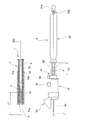
- FIG. 5 is a partial cross-sectional view showing the biopsy needle 1.
- FIG. 6 is a diagram showing the operation unit 8 of the biopsy needle 1.
- the biopsy needle 1 includes an insert 2 inserted into the body, an operation unit (treatment instrument operation unit) 8 for operating the insert 2, and a stylet (core metal). 27.
- the insert 2 is a long member that can be attached to the channel 107 so as to protrude from the distal end of the insertion portion 101 of the ultrasonic endoscope 100.
- the insert 2 includes a needle tube 3 and a cylindrical sheath 7 into which the needle tube 3 is inserted.
- the needle tube 3 is a 22-gauge tubular member that has a distal end and a proximal end and is advanced and retracted by the operation unit 8.
- the material of the needle tube 3 may be a material having flexibility and elasticity that can easily be restored to a linear state even when bent by an external force.
- an alloy material such as a stainless alloy, a nickel titanium alloy, or a cobalt chromium alloy can be employed.
- An opening 31 is formed at the tip of the needle tube 3.
- the opening 31 is formed in a sharp shape that allows the needle tube 3 to puncture the tissue.
- the opening 31 sucks tissue into the needle tube 3.
- the opening 31 provided at the distal end of the needle tube 3 is formed by cutting off the distal end of the tubular member forming the needle tube obliquely with respect to its own axis X1, and is formed sharply so that it can be inserted into a living tissue. ing.
- the specific shape of the opening 31 may be appropriately selected from various known shapes in consideration of the target tissue and the like.
- the sheath 7 includes a distal end coil 71 constituting the distal end portion of the sheath 7, a proximal end coil 72 constituting the proximal end portion of the sheath 7, a connection portion 73, and a resin coating 74. .
- the tip coil 71 is made of a metal wire having a square cross section and is formed in a coil shape.
- the cross-sectional shape of the metal strand of the tip coil 71 is, for example, a rectangle having a thickness of 0.20 ⁇ 0.01 mm and a width of 0.65 mm.
- the inner diameter of the tip coil 71 is ⁇ 1.10 mm.
- the ratio of the outer diameter of the tip coil 71 to the inner diameter of the channel 107 is in the range of 1.0: 0.84 to 1.0: 0.96.
- the initial tension of the tip coil 71 is 2.0 [N] or more.
- the distal end coil 71 is an elongation suppressing portion that suppresses the elongation in the center line direction of the sheath 7 at the distal end portion of the sheath 7.
- the proximal coil 72 is made of a metal wire having a square cross section and is formed into a coil shape.
- the cross-sectional shape of the metal wire of the proximal coil 72 is, for example, a rectangle having a thickness of 0.23 ⁇ 0.01 mm and a width of 0.60 mm.
- the inner diameter of the base end coil 72 is ⁇ 1.10 mm.
- the ratio of the outer diameter of the proximal coil 72 to the inner diameter of the channel 107 is in the range of 1.0: 0.66 to 1.0: 0.84.
- the initial tension of the proximal end coil 72 is 5.0 [N] or more.
- the dimension of the sheath 7 in this embodiment and other specific design values are only specific examples.
- the connecting portion 73 is a cylindrical member for connecting the distal end coil 71 and the proximal end coil 72.
- the connecting portion 73 is fixed to each of the proximal end portion of the distal end coil 71 and the distal end portion of the proximal end coil 72 by brazing.
- the resin coating 74 is attached to the tip coil 71 so as to cover the outer periphery of the tip coil 71.
- the thickness of the resin coating 74 is 0.15 mm or more and 0.2 mm or less.
- the resin coating 74 is formed of, for example, a heat shrinkable tube that is attached to the tip coil 71 after the tip coil 71 is molded.
- the inner surface of the resin coating 74 has a shape that follows the outer surface shape of the tip coil 71. In the present embodiment, the inner surface of the resin coating 74 does not enter the gap between adjacent portions due to the coiled tip coil 71.
- the inner surface of the resin coating 74 is not fixed to the tip coil 71. That is, the resin coating 74 is engaged with the outer surface of the tip coil 71 by a contraction force that causes the resin coating 74 itself to become smaller than the outer diameter of the tip coil 71. Accordingly, a part of the inner surface of the resin coating 74 can be expanded and contracted away from the outer surface of the metal wire of the tip coil 71 when the tip coil 71 is bent and deformed.
- the outer surface of the resin coating 74 has an uneven shape corresponding to the outer surface shape of the tip coil 71.
- the outer surface shape of the resin coating 74 is not particularly limited.
- the outer diameter of the tip coil 71 portion in the sheath 7 is in a range of ⁇ 1.7 mm or more and 1.9 mm or less.
- the operation unit 8 includes an operation main body 9, a sheath adjuster 18 provided on the distal end side of the operation main body 9, and a needle slider 23 provided on the proximal end side of the operation main body 9. Is provided.
- the operation body 9 is made of, for example, ABS resin and has a lumen through which the needle tube 3 and the sheath 7 can be inserted.
- the distal end side of the operation body 9 is inserted into a sheath adjuster 18 formed in a tubular shape.
- the proximal end side of the operation body 9 is inserted into a needle slider 23 formed in a tubular shape.
- the operation main body 9 and the sheath adjuster 18, and the operation main body 9 and the needle slider 23 are engaged with each other by a groove or a projection (not shown) formed on the outer peripheral surface, so that relative rotation around the axis is suppressed, and the axial direction Is slidable.
- a slide lock 51 that can be attached to and detached from the proximal end cap 108 of the ultrasonic endoscope 100 is provided.
- the operation unit 8 can be fixed to the ultrasonic endoscope 100.
- a holder (fixed portion) 52 having a pair of wall portions 52 a and 52 b is provided on the distal end side of the slide lock 51. The holder 52 is fixed to the sheath adjuster 18.
- the pair of wall portions 52a and 52b of the holder 52 are substantially parallel, and the distance between the pair of wall portions 52a and 52b is set to a value that allows the distal end side of the operation unit 109 of the ultrasonic endoscope 100 to fit within the backlash. Is set.
- the distal end portion of the support pipe 53 is inserted into the channel 107 when the biopsy needle 1 is attached to the ultrasonic endoscope 100.
- the support pipe 53 is inserted into the operation body 9.
- the base end of the support pipe 53 is located closer to the base end side (for example, position P1 shown in FIG. 6) than the tip end of the needle slider 23 in a state where the needle slider 23 is most advanced with respect to the operation body 9.
- the sheath 7 is inserted into the support pipe 53, and the base end portion protrudes from the base end of the support pipe 53 and is fixed to the operation body 9 by adhesion or the like.
- the fixing screw 54 is attached to the sheath adjuster 18.
- the fixing screw 54 passes through the sheath adjuster 18 and is fitted in a screw hole (not shown) provided in the operation main body 9.
- the fixing screw 54 is tightened with respect to the operation main body 9, the sheath adjuster 18 is pressed against the operation main body 9, and the sheath adjuster 18 and the operation main body 9 can be fixed in a non-slidable manner.
- the protruding length of the sheath 7 from the channel 107 when the operation unit 8 is fixed to the ultrasonic endoscope 100 can be adjusted.
- the protrusion length can be fixed by the screw 54.
- the axis of the fixing screw 54 may be arranged so as to face the axis of the operation unit 109 housed in the holder 52.
- the fixing screw 54 since the fixing screw 54 is not biased left and right when the operation unit 8 is positioned in the front, it can be easily operated regardless of the operator's dominant hand.
- the axis of the fixing screw 54 is directed toward the axis of the operation unit 109 accommodated in the holder 52, substantially the same effect can be obtained even if the fixing screw 54 is attached to the opposite side of FIG.
- the outer peripheral surface of the distal end portion of the sheath adjuster 18 is provided with irregularities so that the operator can easily grasp it.
- the needle slider 23 is fixed to the proximal end of the needle tube 3. Further, the needle slider 23 is connected to the operation main body 9 so as to be movable with respect to the operation main body 9.
- the proximal end side of the needle tube 3 protrudes from the proximal end of the sheath 7 and is fixed to the needle slider 23. For this reason, by sliding the needle slider 23 with respect to the operation main body 9, the needle tube 3 can be protruded and retracted from the distal end of the sheath 7.
- a stopper 61 is movably attached to the operation main body 9 at the distal end side of the needle slider 23.
- the stopper 61 has a fixing screw 62 and can be fixed to the operation body 9 by tightening the fixing screw 62. As shown in FIG.
- the axis of the fixing screw 62 may be arranged so as to face the axis of the operation unit 109 housed in the holder 52.
- the fixing screw 62 since the fixing screw 62 is not biased left and right when the operation unit 8 is positioned in front, it can be easily operated regardless of the operator's dominant hand.
- the axis of the fixing screw 62 is directed toward the axis of the operation unit 109 that is accommodated in the holder 52, substantially the same effect can be obtained even if the fixing screw 62 is attached facing the opposite side to FIG.
- the fixing screw 62 may be directed in the same direction as the fixing screw 54 described above, or may be directed in directions opposite to each other.
- the needle slider 23 can only move forward with respect to the operation main body 9 to a position where it comes into contact with the stopper 61. Therefore, by adjusting the fixing position of the stopper 61 with respect to the operation main body 9, The maximum protruding length from can be adjusted.
- the operation stroke length (maximum movement amount) L2 of the needle tube 3 by the needle slider 23 is 5% or more of the total length of the sheath 7.
- the operation stroke length L2 of the needle tube 3 by the needle slider 23 may be 40 mm or more.
- the state where the needle slider 23 is located at the position where the needle slider 23 has moved to the limit on the proximal end side of the operation body 9 is the initial state before the biopsy needle 1 is used.
- the tip of the needle tube 3 is in the sheath 7. More specifically, the tip of the needle tube 3 is in the tip coil 71 in the initial state.
- a positional relationship in which the sheath 7 is attached to the channel 107 of the ultrasonic endoscope 100 and the distal end portion of the sheath 7 can be optically observed by the ultrasonic endoscope 100 (see FIG. 4), The tip is located closer to the tip than the tip 105 a of the bending portion 105.
- the position of the tip of the needle tube 3 with respect to the sheath 7 in the initial state varies depending on the influence of the expansion or contraction of the sheath 7 and the extension or contraction of the needle tube 3. Variations in the position of the tip of the needle tube 3 with respect to the sheath 7 are affected by temperature, humidity, the state of attachment of the ultrasonic endoscope 100 to the channel 107, the amount of operating force applied to the biopsy needle 1, and the like.
- the proximal coil 72 may meander to the center line of the needle tube 3 due to the compressive force in the center line direction.
- the distal end of the needle tube 3 is positioned closer to the distal end of the sheath 7 than in the state where the insertion body 2 is not inserted into the channel 107. Is located.
- the initial state is assumed in an environment assumed as a procedure using the biopsy needle 1. Then, as shown in FIG. 5, it is set so that the distal end of the needle tube 3 is always in the distal end coil 71.
- the amount of movement of the needle slider 23 relative to the operation body 9 substantially corresponds to the amount of movement of the tip of the needle tube 3 relative to the sheath 7 (see FIG. 5). That is, when the needle slider 23 moves the needle tube 3 relative to the sheath 7, the movement amount (relative stroke length L1) of the needle tube 3 with respect to the sheath 7 is changed to the actual movement amount (operation stroke length L2) of the needle slider 23. ) Plus the expansion or contraction of the needle tube 3.
- the expansion or contraction of the needle tube 3 depends on the elasticity (elasticity) of the needle tube 3 itself, the magnitude of the frictional resistance between the needle tube 3 and the sheath 7, the meandering state of the sheath 7 in the channel 107, and the needle tube 3 in the sheath 7. Affected by the meandering state.
- the distal end of the needle tube 3 protrudes from the distal end of the sheath 7.
- the protruding length of the needle tube 3 when the needle slider 23 is at the position where the needle slider 23 has moved to the limit on the distal end side of the operation body 9 is shorter than the operation stroke length L2 of the needle slider 23, but is at least 40 mm. Also good.
- An opening 23 a is provided at the proximal end portion of the needle slider 23, and the stylet 27 can be inserted into the needle tube 3 from the proximal end of the needle tube 3.
- the opening 23a is provided with a thread, and a known syringe or the like can be connected to the opening 23a.
- the outer peripheral surface of the distal end portion of the needle slider 23 is provided with irregularities so that the operator can easily grasp it.
- the stylet 27 shown in FIGS. 3 and 5 has a knob 27a that can be attached to the opening 23a of the needle slider 23, and a core 27b fixed to the knob 27a.
- the core 27 b has a cross-sectional shape corresponding to the inner surface shape of the needle tube 3. In the present embodiment, the core 27b has a circular cross section.
- FIG. 7 is a perspective view showing a state in which the biopsy needle 1 and the ultrasonic endoscope 100 are attached.
- 8 to 10 are explanatory views showing the operation of the biopsy needle 1.
- FIG. Hereinafter, a biopsy procedure in which a lesion located in the deep part of the lung is used as a target tissue and the needle tube 3 of the biopsy needle 1 is inserted and cells of the lesion are collected through the inside of the needle tube 3 will be described as an example.
- the operator inserts the insertion portion 101 of the ultrasonic endoscope 100 shown in FIG. 1 into the body, observes with the optical imaging mechanism 103, and appropriately inserts the insertion portion 101 to the vicinity of the target tissue while curving the bending portion 105. Introduce the tip. After introducing the distal end portion of the insertion portion 101, the surgeon determines a site to perform biopsy based on the observation results by the optical imaging mechanism 103 and the ultrasonic scanning mechanism 104.
- the surgeon inserts the insert 2 of the biopsy needle 1 from the distal end side into the channel 107 from the proximal end cap 108 provided in the operation unit 109 of the ultrasonic endoscope 100. Furthermore, as shown in FIG. 7, the surgeon enters the distal end side of the operation unit 109 between the pair of wall portions 52 a and 52 b of the holder 52, and then slide lock 51 provided on the operation unit 8 of the biopsy needle 1. Is engaged with the base end cap 108. Thereby, the operation unit 8 of the biopsy needle 1 is fixed to the ultrasonic endoscope 100 so as not to rotate with respect to the operation unit 109.
- the tip of the needle tube 3 is in the tip coil 71. Since the resin coating 74 is in close contact with the tip coil 71 and the tip coil 71 has an initial tension of 2.0 N or more, the tip coil 71 is generally held in a tightly wound state. When the tip coil 71 is deformed following the curved shape of the channel 107, some of the metal wires of the tip coil 71 are separated from each other, and the resin coating 74 is extended following the curved deformation of the tip coil 71. Variations in the spacing between the strands of the tip coil 71 are suppressed by the resin coating 74 being in close contact with the strands of the tip coil 71.
- the needle tube 3 guided in the channel 107 along the curved flexible tube portion 106 is protected so that the tip of the needle tube 3 does not break through the tip coil 71. Further, due to the frictional resistance between the inner surface of the channel 107 and the outermost surface of the insert 2, contraction and meandering due to compression may be accumulated in the sheath 7 as the insert 2 is pushed into the channel 107. In this case, the distal end of the sheath 7 moves to the proximal end side relative to the needle tube 3, but the distal end of the needle tube 3 is protected because it is located in the distal end coil 71.
- the operator loosens the fixing screw 54 and observes the sheath 7 and the inside of the body with the optical imaging mechanism 103 and the ultrasonic scanning mechanism 104, and moves the sheath adjuster 18 and the operation body 9 relative to each other as shown in FIG.
- the amount of protrusion of the sheath 7 from the distal end of the insertion portion 101 of the ultrasonic endoscope 100 is adjusted to an appropriate amount.
- the operator tightens the fixing screw 54 to fix the protrusion amount.
- the distal end of the needle tube 3 is in the distal end coil 71. Further, the tip of the needle tube 3 is located at any position in the channel 107 between the curved portion 105 and the angle tube 107b, in the angle tube 107b, or in the slope portion 107a.
- the position of the connecting portion 73 in the sheath 7 is further on the proximal end side of the ultrasonic endoscope 100 than the proximal end 105b (see FIG. 4) of the bending portion 105 of the ultrasonic endoscope 100. Specifically, when the distal end of the sheath 7 can be optically observed using the ultrasonic endoscope 100, the connection portion 73 is further proximal than the proximal end 105 b of the bending portion 105.
- the distal end coil 71 and the needle tube are located in the region from the proximal end 105b of the bending portion 105 to the distal end of the insertion portion 101. Only 3 are arranged.
- proximal end coil 72 is arranged in the region on the proximal end side of the ultrasonic endoscope 100 from the proximal end 105b of the bending portion 105, it is possible to prevent the sheath 7 in this region from meandering. .
- the operator moves the stopper 61 while considering the distance to the target tissue T to be biopsied, and fixes it to the operation body 9 at a desired position.
- the maximum protrusion length of the needle tube 3 is adjusted.
- the surgeon advances the needle slider 23 toward the distal end side of the operation unit 8.
- the needle tube 3 protrudes from the sheath 7 as shown in FIG.
- the distal end of the needle tube 3 is the distal coil of the sheath 7.
- 71 passes through the angle tube 107b while being guided by 71 and reaches the slope portion 107a.
- the distal end of the needle tube 3 When the distal end of the needle tube 3 is moved to the distal end side of the ultrasonic endoscope 100 starting from the angle tube 107b, and the distal end of the needle tube 3 is moved to the distal end side of the ultrasonic endoscope 100 starting from the slope portion 107a. Even in this case, as described above, the distal end of the needle tube 3 protrudes from the distal end of the sheath 7 while being guided by the distal end coil 71.
- the distal end of the needle tube 3 is punctured into the tissue and is pushed forward to the target tissue T to be biopsied.
- the needle tube 3 exposed to the outside from the surface of the tissue can be observed by the optical imaging mechanism 103, and the tip side portion of the needle tube 3 inserted into the tissue is observed by the ultrasonic scanning mechanism 104. Can do.
- the surgeon can observe an ultrasonic image based on the ultrasonic wave received by the ultrasonic scanning mechanism 104 with the ultrasonic observation unit 115 shown in FIG. With reference to the image of the needle tube 3 clearly displayed on the ultrasonic observation unit 115, the operator causes the tip of the needle tube 3 to reach the target tissue T on which biopsy is performed.
- the surgeon pushes out the tissue that has not entered into the needle tube 3 and is not subjected to biopsy with the stylet 27, and pulls out the stylet 27 from the insert 2 and the operation unit 8. Thereby, a through hole extending from the distal end of the needle tube 3 to the proximal end of the needle slider 23 is generated.
- the surgeon connects a syringe or the like to the proximal end of the needle slider 23 and sucks the inside of the needle tube 3, and sucks and collects cells of the target tissue T to be biopsied from the tip of the needle tube 3.
- the needle slider 23 is retracted toward the proximal end side of the operation unit 8 and the distal end of the needle tube 3 is accommodated in the sheath 7. Thereby, the needle tube 3 comes out of the tissue.
- the operator removes the slide lock 51 from the proximal end cap 108 of the operation unit 109 of the ultrasonic endoscope 100 and removes the biopsy needle 1 from the channel 107. Finally, the operator removes the ultrasonic endoscope 100 from the patient and ends the series of treatments.
- the distal end coil 71 is prevented from meandering in the channel 107 and the bending performance of the bending portion 105 is suppressed, so that the sheath accompanying the advancement and retraction of the needle tube 3 is suppressed.
- the suppression of the elongation of 7 and the flexibility of the sheath 7 are compatible.
- the distal end coil 71 and the proximal end coil 72 are provided with a difference in flexibility so that the distal end coil 71 is more flexible than the proximal end coil 72.
- the present embodiment it is possible to prevent the bending performance of the bending portion 105 from being lowered when the biopsy needle 1 is attached to the ultrasonic endoscope 100, and the center line of the sheath 7 in the channel 107. Expansion and contraction in the direction and meandering of the sheath 7 can be suppressed.
- the resin coating 74 disposed so as to be in close contact with the outer surface of the tip coil 71 prevents the metal wire of the tip coil 71 from being extremely separated during the bending deformation of the tip coil 71, so that the needle tube is interposed between the metal wires. 3 can be prevented from entering, and the sheath 7 can be prevented from being broken by the needle tube 3.
- connection portion 73 is further on the proximal end side of the ultrasonic endoscope 100 than the proximal end of the bending portion 105, the proximal end coil 72 is also connected to the bending portion even when the position of the sheath 7 is adjusted in the channel 107. Do not enter 105. For this reason, the bending ability of the bending portion 105 does not fluctuate before and after such position adjustment.
- the sheath 7 may have a configuration in which the distal end coil 71 is provided over the entire length of the sheath 7 and does not include the proximal end coil 72 and the connection portion 73. Further, as the configuration of the sheath 7, there may be a configuration in which the proximal end coil 72 is provided over the entire length of the sheath 7 and the distal end coil 71 and the connection portion 73 are not provided. In these cases, the resin coating 74 may be provided on the sheath 7 so as to cover the region where the tip of the needle tube 3 can be located at the tip of the sheath 7.
- Example of this invention is shown.
- a specific configuration of the tip coil 71 described in the above embodiment is shown, and its operation and effect will be described.
- the coil from which a structure differs is shown as a comparative example for showing the effect of this invention.
- Table 1 above is a table showing the initial tension and spring constant of the coil in this example and the comparative example.
- ten coil samples were prepared for each of Example 1, Example 2, and Comparative Example 1.
- the dimensions of these coil samples are as shown in the above embodiment.
- the resin coating demonstrated in the said embodiment is provided in the coil sample, the influence of the resin coating with respect to the initial tension of a coil sample is a level which can be disregarded.
- these coil samples were placed on a respiratory ultrasonic endoscope having a channel with an inner diameter of 2.0 mm or more and 2.2 mm or less. Insertion was performed, and the extent and occurrence frequency of elongation in the direction of the center line of the coil sample were examined.
- FIG. 11 is a graph for comparing the defect rates in Example 1, Example 2, and Comparative Example 1 of the present invention.
- the horizontal axis indicates the average initial tension of the coils in Example 1, Example 2, and Comparative Example 1 of the present invention
- the vertical axis indicates the defect rate.
- elongation (defect) of 2 mm or more occurs at a frequency of 20%.
- FIG. 12 is a graph for comparing the amount of sheath elongation in Example 1, Example 2, and Comparative Example 1 of the present invention.
- the horizontal axis indicates the average initial tension of the coil in Example 1, Example 2, and Comparative Example 1 of the present invention
- the vertical axis indicates the amount of elongation of the coil.
- the clearance between the channel inner diameter of the ultrasonic endoscope and the sheath outer diameter of the ultrasonic biopsy needle is 1.0: 0.84 to 1.0: 0.96.
- production of sheath elongation can be suppressed because the initial tension of a sheath exceeds 2.0 N under the conditions which exist in the range.
- production of sheath extension can further be suppressed because the initial tension of a sheath exceeds 2.4N.
- the coiled sheath satisfying such conditions can significantly suppress the occurrence of elongation compared to the conventional case. For this reason, by using this as the sheath of the ultrasonic biopsy needle for the respiratory tract, it is possible to suppress the extension of the distal end side of the sheath at the time of puncture and perform the procedure while observing a stable and accurate image.
- a curved or bent through hole may be formed in the distal end hard portion 102 in the same manner as the angle tube 107 b described above. In this case, the angle tube 107b is unnecessary.
- the connecting portion 73 may be one in which the distal end coil 71 and the proximal end coil 72 are welded instead of connecting the distal end coil 71 and the proximal end coil 72 with a cylindrical member.
- the connection part 73 may be a simple boundary position where the configuration of the strands is switched at this position. For example, in the coil in which the strands are wound continuously from the distal end to the proximal end of the sheath 7, the cross-sectional area, sectional shape, hardness, etc. of the strands are switched at the position of the connecting portion 73. A difference in flexibility may be provided.
- the biopsy needle 1 may not have the resin coating 74.
- an ultrasonic biopsy needle that achieves both the suppression of the extension of the sheath accompanying the advancement and retraction of the needle tube and the improvement of the flexibility of the sheath.
Abstract
Description
本願は、2014年8月7日に、日本国に出願された特願2014-161576号に基づき優先権を主張し、その内容をここに援用する。 The present invention relates to a biopsy needle used with an ultrasonic endoscope.
This application claims priority on August 7, 2014 based on Japanese Patent Application No. 2014-161576 filed in Japan, the contents of which are incorporated herein by reference.
しかし、可撓性が高いシースは一般的に伸縮性にも富むので、シースの伸びの抑制とシースの可撓性の向上とを両立することは、特に細径で非力な呼吸器用内視鏡に適用される超音波生検針において困難である。可撓性が高いシースの伸びが生検針の穿刺時に発生すると、伸びた分だけシースが内視鏡の先端から突出し、突出したシースが組織を押すことになる。この場合、組織と超音波振動子の間の距離が離間することで、超音波画像が不鮮明になる。 The respiratory endoscope has a smaller diameter than the digestive endoscope. For this reason, the amount of bending force of the bending portion that is actively bent in the respiratory endoscope is weaker than that of the bending portion of the digestive endoscope. The sheath of the biopsy needle applied to the respiratory endoscope is required to be flexible so that the bending ability of the respiratory endoscope does not decrease when the biopsy needle is inserted into the respiratory endoscope.
However, since a highly flexible sheath is generally rich in stretchability, it is particularly difficult to reduce the extension of the sheath and improve the flexibility of the sheath. Difficult in ultrasonic biopsy needles applied to. When stretching of the highly flexible sheath occurs at the time of puncturing the biopsy needle, the sheath projects from the distal end of the endoscope by the stretched amount, and the projecting sheath pushes the tissue. In this case, the ultrasonic image becomes unclear because the distance between the tissue and the ultrasonic transducer is separated.
本発明の一実施形態について説明する。図1は、生検針1および超音波内視鏡100を備えた本実施形態の生検システム150の概略構成を示す図である。図2は、生検システム150の内視鏡である超音波内視鏡100の先端部分の断面図である。
図1に示す本実施形態の超音波生検針1(以下、単に「生検針1」と称する。)は、生検システム150の一部として、超音波内視鏡100と組み合わせて生検に使用される穿刺針である。 (First embodiment)
An embodiment of the present invention will be described. FIG. 1 is a diagram showing a schematic configuration of a
The ultrasonic biopsy needle 1 (hereinafter, simply referred to as “
本実施形態では、例えば呼吸器の治療のために、挿入部の外径が細く2方向に湾曲可能な内視鏡を用いているが、例えば消化器の処置を行う場合等には、外径は太いが操作自由度の高い4方向に湾曲可能な内視鏡を用いてもよい。 The
In the present embodiment, for example, an endoscope having a thin outer diameter that can be bent in two directions is used for respiratory treatment. However, for example, when performing digestive organ treatment, the outer diameter is used. However, an endoscope that can be bent in four directions with a high degree of freedom of operation may be used.
湾曲部105と可撓管部106とのそれぞれの内部には、チャンネル107と、送気送水や吸引などを行うための図示しない管路とが設けられている。 The
Inside each of the bending
チャンネル107の一端は先端硬質部102の先端部近傍に開口され、チャンネル107の他端は操作部109の先端側の側面に開口されている。チャンネル107の他端には、フランジ状に形成された基端口金108が固定されている。基端口金108には、超音波内視鏡100とともに使用される生検針1を固定することができる。本実施形態のチャンネル107の内径は、2.0mm以上2.2mm以下である。本実施形態におけるチャンネル107の内径は、消化器用の内視鏡におけるチャンネルの内径よりも小さい。 The
One end of the
挿入部101の軸線C1に対するスロープ部107aの中心線C2の傾斜角度は、処置対象となる部位等に対応して適宜設定されてよい。本実施形態では、スロープ部107aの中心線C2は、挿入部101の軸線C1に対して、針管3が超音波画像として取得可能な向きに突出する角度(たとえば23°以上28°以下)をなして傾斜している。 The
The inclination angle of the center line C2 of the
針管3の材質としては、可撓性を有しているとともに、外力により曲げられても容易に直線状態に復元する弾性を有する材質であってもよい。たとえば、針管3の材料としては、ステンレス合金、ニッケルチタン合金、コバルトクロム合金などの合金材料を採用することができる。 The
The material of the
針管3の先端に設けられた開口31は、針管を形成する管状部材の先端を自身の軸線X1に対して斜めに切り落とすことにより形成されており、生体組織に刺入できるように鋭利に形成されている。開口31の具体的形状は、対象とする組織等を考慮して公知の各種形状から適宜選択されてよい。 An
The
先端コイル71の内径はφ1.10mmである。チャンネル107の内径に対する先端コイル71の外径の比は、1.0:0.84から1.0:0.96の範囲内にある。先端コイル71の初張力は2.0[N]以上である。
先端コイル71は、シース7の先端部分においてシース7の中心線方向への伸びを抑制する伸び抑制部となっている。 The
The inner diameter of the
The
なお、本実施形態におけるシース7の寸法その他具体的な設計値は、あくまでも具体的な例示である。 The inner diameter of the
In addition, the dimension of the
針管3の基端側は、シース7の基端から突出して針スライダ23に固定されている。このため、針スライダ23を操作本体9に対して摺動することで、シース7の先端から針管3を突没させることができる。針スライダ23の先端側において、ストッパ61が操作本体9に対して移動可能に取り付けられている。ストッパ61は固定ネジ62を有し、固定ネジ62を締め込むことで、操作本体9に対して固定することができる。図1に示すように、固定ネジ62の軸線は、ホルダ52に収まった操作部109の軸線に向かうように配置されていてもよい。これにより、操作部8を正面に位置させたときに固定ネジ62が左右に偏らないため、術者の利き手によらず容易に操作することができる。固定ネジ62の軸線がホルダ52に収まった操作部109の軸線に向かっていれば、固定ネジ62が図1と反対側に向いて取り付けられていても、概ね同様の効果を得ることができる。 The
The proximal end side of the
芯27bは、針管3の内面形状に対応した断面形状を有している。本実施形態では芯27bは断面円形である。 The
The core 27 b has a cross-sectional shape corresponding to the inner surface shape of the
以下では、肺の深部に位置する病変を対象組織として生検針1の針管3を刺入し、針管3の内部を通じて病変の細胞などを回収する生検の処置を例に説明する。 The operation at the time of use of the
Hereinafter, a biopsy procedure in which a lesion located in the deep part of the lung is used as a target tissue and the
また、先端コイル71の方が基端コイル72よりも可撓性が高くなるように、先端コイル71と基端コイル72とに可撓性の差がつけられている。このため、本実施形態では、生検針1が超音波内視鏡100に取り付けられた状態において湾曲部105の湾曲性能が下がることを抑制することができ、またチャンネル107内におけるシース7の中心線方向における伸縮やシース7が蛇行することを抑制することができる。 As described above, in the present embodiment, the
Further, the
また、シース7の構成として、シース7の全長に亘って基端コイル72が設けられていて先端コイル71及び接続部73を有しない構成もあり得る。
これらの場合、樹脂被覆74は、シース7の先端部分で針管3の先端が位置し得る領域を覆うようにシース7に設けられていればよい。 The
Further, as the configuration of the
In these cases, the
本発明の実施例として、上記実施形態で説明した先端コイル71の具体的な構成を示し、その作用および効果について説明する。また、本発明の効果を示すための比較例として、構成が異なるコイルを示す。 The Example of this invention is shown.
As an example of the present invention, a specific configuration of the


図11は、本発明の実施例1、実施例2、および比較例1における不良率を比較するためのグラフである。図11において、横軸は本発明の実施例1、実施例2、および比較例1におけるコイルの平均初張力を示しており、縦軸は不良率を示している。図11及び上記表2に示すように、比較例1において、20%の頻度で2mm以上の伸び(不良)が発生している。 In a biopsy using an ultrasonic endoscope, if the sheath extends 2 mm or more, the ultrasonic image is often distorted because the sheath pushes the tissue away from the ultrasonic endoscope. For this reason, the frequency of occurrence of defects (defective rate (%)) was examined by considering defects with elongation of 2 mm or more as defects.
FIG. 11 is a graph for comparing the defect rates in Example 1, Example 2, and Comparative Example 1 of the present invention. In FIG. 11, the horizontal axis indicates the average initial tension of the coils in Example 1, Example 2, and Comparative Example 1 of the present invention, and the vertical axis indicates the defect rate. As shown in FIG. 11 and Table 2 above, in Comparative Example 1, elongation (defect) of 2 mm or more occurs at a frequency of 20%.
従って、コイルの平均初張力が1.85Nと2.43Nとの間に、不良の発生がゼロとなる閾値が存在することが強く示唆されている。 As can be seen from Tables 1 and 2, with respect to the average amount of elongation, any of Examples 1 and 2 and Comparative Example 1 does not cause an elongation of 2 mm. However, whether the average initial tension is between 1.85 N and 2.43 N, as shown in FIG. FIG. 12 is a graph for comparing the amount of sheath elongation in Example 1, Example 2, and Comparative Example 1 of the present invention. In FIG. 12, the horizontal axis indicates the average initial tension of the coil in Example 1, Example 2, and Comparative Example 1 of the present invention, and the vertical axis indicates the amount of elongation of the coil. As shown in FIG. 12, it can be seen that there is a threshold value related to the amount of elongation between the average initial tension indicated by the rectangular solid portion between 1.85 N and 2.43 N.
Therefore, it is strongly suggested that there is a threshold between which the average initial tension of the coil is 1.85N and 2.43N, and the occurrence of defects is zero.
このように、初張力が2[N]付近を境に、伸びの発生が有意に減少していると言える。 Since the spring constants of Examples 1 and 2 and Comparative Example 1 are substantially the same, the relationship between the outer diameter of the sheath in the ultrasonic biopsy needle and the inner diameter of the channel of the ultrasonic endoscope is within the range shown in the above embodiment. It can be seen that the initial tension value has a particularly large correlation with the suppression of elongation.
Thus, it can be said that the occurrence of elongation is significantly reduced around the initial tension of around 2 [N].
たとえば、湾曲又は屈曲した筒状のアングルチューブ107bに代えて、上記のアングルチューブ107bと同様に湾曲又は屈曲した貫通孔(アングル部)が先端硬質部102に形成されていてもよい。この場合アングルチューブ107bは不要である。 As mentioned above, although one Embodiment and the Example of this invention were explained in full detail with reference to drawings, the concrete structure is not restricted to this Embodiment, The design change etc. of the range which does not deviate from the summary of this invention are included. included.
For example, instead of the curved or bent
3 針管
7 シース
74 樹脂被覆
8 操作部
100 超音波内視鏡
102 先端硬質部
103 光学撮像機構
105 湾曲部
105a 湾曲部の先端
105b 湾曲部の基端
106 可撓管部
107 チャンネル
107a スロープ部
107b アングルチューブ
107c チャンネルチューブ
109 操作部
110 湾曲操作機構 DESCRIPTION OF
Claims (5)
- 超音波内視鏡のチャンネルに挿通されるシースと、
前記シースに進退可能に挿通される針管と、
前記シースの基端に接続され、前記針管を進退操作するための操作部と、
を備え、
前記シースは、前記シースの先端が前記超音波内視鏡の光学撮像機構の視野内に位置する状態において、前記超音波内視鏡の湾曲部基端よりも先端側に位置する伸び抑制部を有し、
前記伸び抑制部は、金属製のコイルからなり、前記チャンネルの内径に対する前記コイルの外径の比が1.0:0.84から1.0:0.96の範囲内にあり、前記コイルの初張力が2.0[N]以上であり、前記針管の進退に伴うシースの伸びを抑制する
超音波生検針。 A sheath inserted through the channel of the ultrasonic endoscope;
A needle tube inserted through the sheath so as to be able to advance and retract;
An operation unit connected to the proximal end of the sheath and for advancing and retracting the needle tube;
With
The sheath includes an extension suppressing portion positioned on the distal end side of the proximal end of the bending portion of the ultrasonic endoscope in a state where the distal end of the sheath is positioned in the field of view of the optical imaging mechanism of the ultrasonic endoscope. Have
The elongation suppressing portion is made of a metal coil, and a ratio of an outer diameter of the coil to an inner diameter of the channel is in a range of 1.0: 0.84 to 1.0: 0.96, An ultrasonic biopsy needle that has an initial tension of 2.0 [N] or more and suppresses elongation of the sheath accompanying advancement and retraction of the needle tube. - 前記シースは、前記シースの全長に亘り前記コイルから形成される
請求項1に記載の超音波生検針。 The ultrasonic biopsy needle according to claim 1, wherein the sheath is formed from the coil over the entire length of the sheath. - 前記コイルは、
金属素線と、
前記金属素線を被覆する樹脂被覆と、
を有する
請求項1に記載の超音波生検針。 The coil is
Metal wire,
A resin coating for coating the metal strand;
The ultrasonic biopsy needle according to claim 1. - 前記樹脂被覆の厚さは、0.15mm以上0.2mm以下である
請求項3に記載の超音波生検針。 The ultrasonic biopsy needle according to claim 3, wherein a thickness of the resin coating is 0.15 mm or more and 0.2 mm or less. - 前記チャンネルの内径が2.0mm以上2.2mm以下であり、
前記チャンネルの先端側には、前記超音波生検針を前記超音波内視鏡の振動子に対して傾斜して突出させるための角度が固定されたスロープ部が形成され、
前記シースに対する前記針管の最大移動量は、前記シースの全長の5%以上の長さである
請求項1に記載の超音波生検針。 The inner diameter of the channel is 2.0 mm or more and 2.2 mm or less,
On the distal end side of the channel, a slope portion is formed in which an angle for inclining and projecting the ultrasonic biopsy needle with respect to the transducer of the ultrasonic endoscope is formed,
The ultrasonic biopsy needle according to claim 1, wherein a maximum movement amount of the needle tube with respect to the sheath is 5% or more of a total length of the sheath.
Priority Applications (4)
| Application Number | Priority Date | Filing Date | Title |
|---|---|---|---|
| EP15830145.7A EP3178406A4 (en) | 2014-08-07 | 2015-05-22 | Ultrasonic biopsy needle |
| CN201580001884.5A CN105555201A (en) | 2014-08-07 | 2015-05-22 | Ultrasonic biopsy needle |
| JP2015551640A JP5861020B1 (en) | 2014-08-07 | 2015-05-22 | Ultrasound biopsy needle |
| US15/084,048 US20160206278A1 (en) | 2014-08-07 | 2016-03-29 | Ultrasonic biopsy needle |
Applications Claiming Priority (2)
| Application Number | Priority Date | Filing Date | Title |
|---|---|---|---|
| JP2014-161576 | 2014-08-07 | ||
| JP2014161576 | 2014-08-07 |
Related Child Applications (1)
| Application Number | Title | Priority Date | Filing Date |
|---|---|---|---|
| US15/084,048 Continuation US20160206278A1 (en) | 2014-08-07 | 2016-03-29 | Ultrasonic biopsy needle |
Publications (1)
| Publication Number | Publication Date |
|---|---|
| WO2016021275A1 true WO2016021275A1 (en) | 2016-02-11 |
Family
ID=55263554
Family Applications (1)
| Application Number | Title | Priority Date | Filing Date |
|---|---|---|---|
| PCT/JP2015/064734 WO2016021275A1 (en) | 2014-08-07 | 2015-05-22 | Ultrasonic biopsy needle |
Country Status (5)
| Country | Link |
|---|---|
| US (1) | US20160206278A1 (en) |
| EP (1) | EP3178406A4 (en) |
| JP (1) | JP5861020B1 (en) |
| CN (1) | CN105555201A (en) |
| WO (1) | WO2016021275A1 (en) |
Families Citing this family (3)
| Publication number | Priority date | Publication date | Assignee | Title |
|---|---|---|---|---|
| CN105852911B (en) * | 2016-05-26 | 2019-11-29 | 苏州佳世达电通有限公司 | Supersonic waveguide and medical system |
| US20210045720A1 (en) * | 2018-03-14 | 2021-02-18 | Hoya Corporation | Covered coil sheath for biopsy needle, biopsy needle assembly, and method of forming covered coil sheath |
| WO2022022169A1 (en) * | 2020-07-29 | 2022-02-03 | 南微医学科技股份有限公司 | Endoscopic surgical instrument and protective device used therefor |
Citations (4)
| Publication number | Priority date | Publication date | Assignee | Title |
|---|---|---|---|---|
| JPH09149905A (en) * | 1995-11-30 | 1997-06-10 | Olympus Optical Co Ltd | Processing tool for endoscope |
| JPH10118072A (en) * | 1996-10-17 | 1998-05-12 | Olympus Optical Co Ltd | Intra-celom ultrasonic probe apparatus |
| JP2000232983A (en) * | 1999-02-15 | 2000-08-29 | Fuji Photo Optical Co Ltd | Tissue sampling device |
| JP2005052408A (en) * | 2003-08-05 | 2005-03-03 | Olympus Corp | Treatment instrument for endoscope |
Family Cites Families (9)
| Publication number | Priority date | Publication date | Assignee | Title |
|---|---|---|---|---|
| US5690613A (en) * | 1996-12-06 | 1997-11-25 | Medtronic, Inc. | Rapid exchange high pressure transition for high pressure catheter with non-compliant balloon |
| JPH11276422A (en) * | 1998-03-31 | 1999-10-12 | Fuji Photo Optical Co Ltd | Ultrasonic endoscope |
| WO2012039199A1 (en) * | 2010-09-23 | 2012-03-29 | オリンパスメディカルシステムズ株式会社 | Bendable catheter |
| JP2012120573A (en) * | 2010-12-06 | 2012-06-28 | Olympus Corp | Endoscope |
| US20120197119A1 (en) * | 2011-01-28 | 2012-08-02 | Olympus Medical Systems Corp. | Treatment instrument |
| CN103249365B (en) * | 2011-03-25 | 2015-06-24 | 奥林巴斯医疗株式会社 | Tool for biopsy and tissue collecting method |
| JP5302469B2 (en) * | 2011-05-27 | 2013-10-02 | オリンパスメディカルシステムズ株式会社 | Ultrasound puncture needle |
| JP5379249B2 (en) * | 2012-01-13 | 2013-12-25 | 富士フイルム株式会社 | Tissue collection device |
| JP6006438B2 (en) * | 2013-03-05 | 2016-10-12 | クック・メディカル・テクノロジーズ・リミテッド・ライアビリティ・カンパニーCook Medical Technologies Llc | Endoscopic biopsy needle with coil sheath |
-
2015
- 2015-05-22 WO PCT/JP2015/064734 patent/WO2016021275A1/en active Application Filing
- 2015-05-22 JP JP2015551640A patent/JP5861020B1/en active Active
- 2015-05-22 CN CN201580001884.5A patent/CN105555201A/en active Pending
- 2015-05-22 EP EP15830145.7A patent/EP3178406A4/en not_active Withdrawn
-
2016
- 2016-03-29 US US15/084,048 patent/US20160206278A1/en not_active Abandoned
Patent Citations (4)
| Publication number | Priority date | Publication date | Assignee | Title |
|---|---|---|---|---|
| JPH09149905A (en) * | 1995-11-30 | 1997-06-10 | Olympus Optical Co Ltd | Processing tool for endoscope |
| JPH10118072A (en) * | 1996-10-17 | 1998-05-12 | Olympus Optical Co Ltd | Intra-celom ultrasonic probe apparatus |
| JP2000232983A (en) * | 1999-02-15 | 2000-08-29 | Fuji Photo Optical Co Ltd | Tissue sampling device |
| JP2005052408A (en) * | 2003-08-05 | 2005-03-03 | Olympus Corp | Treatment instrument for endoscope |
Non-Patent Citations (1)
| Title |
|---|
| See also references of EP3178406A4 * |
Also Published As
| Publication number | Publication date |
|---|---|
| EP3178406A4 (en) | 2018-05-02 |
| JP5861020B1 (en) | 2016-02-16 |
| CN105555201A (en) | 2016-05-04 |
| US20160206278A1 (en) | 2016-07-21 |
| JPWO2016021275A1 (en) | 2017-04-27 |
| EP3178406A1 (en) | 2017-06-14 |
Similar Documents
| Publication | Publication Date | Title |
|---|---|---|
| JP5953441B2 (en) | Biopsy system | |
| JP5629043B1 (en) | Biopsy system | |
| US9820724B2 (en) | Endoscope puncture needle and biopsy system | |
| JP5942060B1 (en) | Endoscopic puncture needle | |
| JP5985129B1 (en) | Endoscopic puncture needle | |
| WO2016047202A1 (en) | Endoscope puncture needle | |
| JP5861020B1 (en) | Ultrasound biopsy needle | |
| WO2016042849A1 (en) | Biopsy system | |
| JP5861019B1 (en) | Ultrasound biopsy needle | |
| JP5893814B1 (en) | Tissue collection system | |
| JP6284464B2 (en) | Endoscopic puncture needle | |
| US20220071609A1 (en) | Endoscope puncture needle | |
| WO2015190187A1 (en) | Endoscopic treatment instrument and biopsy system | |
| JP5985131B1 (en) | Endoscopic puncture needle and biopsy system | |
| JP5985128B1 (en) | Biopsy system and treatment tool | |
| JP5945651B1 (en) | Biopsy needle |
Legal Events
| Date | Code | Title | Description |
|---|---|---|---|
| WWE | Wipo information: entry into national phase |
Ref document number: 201580001884.5 Country of ref document: CN |
|
| ENP | Entry into the national phase |
Ref document number: 2015551640 Country of ref document: JP Kind code of ref document: A |
|
| 121 | Ep: the epo has been informed by wipo that ep was designated in this application |
Ref document number: 15830145 Country of ref document: EP Kind code of ref document: A1 |
|
| NENP | Non-entry into the national phase |
Ref country code: DE |
|
| REEP | Request for entry into the european phase |
Ref document number: 2015830145 Country of ref document: EP |
|
| WWE | Wipo information: entry into national phase |
Ref document number: 2015830145 Country of ref document: EP |