WO2016017560A1 - ソフトウェア検証システムおよび制御装置 - Google Patents
ソフトウェア検証システムおよび制御装置 Download PDFInfo
- Publication number
- WO2016017560A1 WO2016017560A1 PCT/JP2015/071185 JP2015071185W WO2016017560A1 WO 2016017560 A1 WO2016017560 A1 WO 2016017560A1 JP 2015071185 W JP2015071185 W JP 2015071185W WO 2016017560 A1 WO2016017560 A1 WO 2016017560A1
- Authority
- WO
- WIPO (PCT)
- Prior art keywords
- test
- software
- inspection
- unit
- verification system
- Prior art date
- Legal status (The legal status is an assumption and is not a legal conclusion. Google has not performed a legal analysis and makes no representation as to the accuracy of the status listed.)
- Ceased
Links
Images



Classifications
-
- G—PHYSICS
- G06—COMPUTING OR CALCULATING; COUNTING
- G06F—ELECTRIC DIGITAL DATA PROCESSING
- G06F11/00—Error detection; Error correction; Monitoring
- G06F11/28—Error detection; Error correction; Monitoring by checking the correct order of processing
-
- G—PHYSICS
- G06—COMPUTING OR CALCULATING; COUNTING
- G06F—ELECTRIC DIGITAL DATA PROCESSING
- G06F11/00—Error detection; Error correction; Monitoring
- G06F11/36—Prevention of errors by analysis, debugging or testing of software
Definitions
- the present invention relates to a verification system for verifying software and a control device equipped with the software.
- a microcontroller (hereinafter referred to as a microcomputer) incorporating a central processing unit, ROM, RAM, input / output signal processing device, and the like is used as a control device for automobile engine control and the like.
- the software executed by the microcomputer is generally composed of an application program that performs control processing, a device driver that performs input / output, and an operating system (OS), etc., so that the control target performs the desired control operation (for example, , See Patent Document 1).
- OS operating system
- Such a control device is required to have high safety because it directly controls the safety of the vehicle occupant by controlling the vehicle (see, for example, Patent Document 2).
- Verification with a higher coverage rate is required, and compared to a system that is not related to safety, it requires increasing development man-hours.
- an object of the present invention is to divide a large piece of software into small parts, verify each part, combine the results with the entire system, and proceed with the verification while integrating the verification results for each part.
- Another object of the present invention is that not only the conditions existing in the verification target software but also the conditions as design information are given to the verification conditions, thereby limiting the verification range and enabling comprehensive verification to large-scale software. There is to do.
- the software verification system of the present invention inputs a source code of a control program having a plurality of functions dependent on input / output, and verifies the control program;
- a test site extraction unit that divides and extracts a source code into a plurality of test sites by the plurality of functional units, and a test result output related to one test site among the plurality of test sites, and a test of the next test site that is continuous
- a first constraint equation creating unit that creates a first constraint equation that defines a range, wherein the plurality of examination sites are sequentially inspected based on the first constraint equation.
- inspection means execution part, the test device, and the test result. It is the figure which showed the inspection type output pattern.
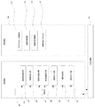
- FIG. 1 is a configuration diagram showing the configuration of the software verification system according to the embodiment of the present invention.
- the inspection device (inspection tool) 0102 is intended to inspect the software 0106 as a whole.
- the term “inspection” here refers to exhaustively searching for possible states of the source code within the verification range defined by the inspection formula inserted in the source code of the software 0106, and verifying that the desired state is obtained. Say.
- the software 0106 is control software installed in a control unit for controlling the automobile as will be described later with reference to FIG.
- the inspection condition setting unit 0103 first, the inspection object software 0108 is extracted as a software part from the inspection part 106 by the inspection part extraction unit 0110, and then the inspection expression is inserted by the inspection expression insertion unit 0111.
- the inspection formula is inserted as a pre-post condition determination unit 0107 and a determination result output unit 0109 that outputs a determination result before or after execution of a processing unit that performs predetermined processing in 0108.
- the value verification range
- the value is obtained before the execution of the processing unit (processing for calculating the output value with respect to the predetermined input value, etc.)
- the value is obtained before the execution of the processing unit (processing for calculating the output value with respect to the predetermined input value, etc.)
- the value verification range
- a possible value (design value or the like) of the output value of the processing unit for the input value specified by the precondition is inserted as a postcondition.
- the inspection execution unit 0104 uses the inspection unit 0113 to comprehensively verify the software component into which the inspection formula is inserted as the inspection unit input software 0101 using the inspection unit 0113.
- the inspection result output unit 0114 outputs the inspection result obtained from the inspection device 0113 to the user or the output device and also outputs it to the required specification input unit 0105.
- Requirement specification input unit 0105 inputs the inspection result as a first constraint equation using constraint equation input unit 0118.
- the check expression input unit 0105 holds the check expression input from the user in the check expression holding unit 0116 as the second constraint expression.
- the constraint integration unit 0117 integrates the first constraint equation and the second constraint equation and outputs them to the check expression insertion unit.
- the inspection unit indicates a component constituting the software, and one function of C language is an example of the unit. However, other granularity can be set and is specified in this example. It is not something.
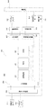
- FIG. 2 is a system configuration diagram for realizing the present invention.
- the processing unit 301 includes a computing device of a computer, the storage device 302 includes a disk device and a memory device, and the input / output device 303 includes a monitor, a keyboard, a network, a printer, and the like.
- the processing device 301 includes the inspection site extraction unit 305, the inspection expression insertion unit 306, the wrinkle inspection means activation unit 307, the wrinkle inspection result output unit 308, the inspection expression input unit 309, the constraint integration unit 310, and the inspection expression input unit 311.
- the In the storage device the program code 312 for storing the software 0106, the inspection formula holding unit 313, the inspection result storage unit 314, and the inspection target software 315 are arranged.
- FIG. 3 shows the configuration of an automobile engine control system which is one of the control systems targeted by the present invention.
- the control unit 301 is composed of a microcontroller 302 (CPU), a signal input circuit 309, an actuator drive circuit 312 and a communication circuit 311. Based on the external information obtained from the sensor 1311 and sensor 2 316 via the signal input circuit 309, Control is performed by driving the actuator 314 via the drive circuit 310. Further, for some signals, control processing is performed using input / output from another control device 316 obtained from the communication line 217 via the communication circuit 311.
- the microcontroller 302 includes an input circuit 303, an arithmetic device 304, a volatile read / write memory 305 (RAM), a read only memory 306 (ROM), an interrupt control device 307, a memory protection device 308, an output circuit 309, a communication control device 310, Consists of
- Software 0106 is stored in the read-only memory 306 and is executed by the microcontroller 302 to perform a predetermined control process.
- FIG. 4a shows the operation of the examination site extraction unit.
- the examination part extraction unit is a part that extracts a specific part of the program code of the software 0106 from the program code storage unit 312 and outputs a partial program component.
- an extraction start point which is a point at which extraction is started, is searched 401, and then an extraction end point is searched 402.
- the program code corresponding to the end point from the start point is cut out 403 as an inspection part, the inspection expression generation unit is called 404, and the inspection expression is inserted into the program code extracted as the inspection part. It is determined whether or not all target modules have been extracted 405. If all target extraction has been completed, the operation ends 405.
- Fig. 4b shows the operation of the check expression generator.
- the check expression generation unit is a part that inputs a program code or a part of the program code and outputs a program code in which the check expression is inserted.
- the objective is to input conditional expression patterns from the check expression storage unit 313, create check expression information, and store them in the constraint integration unit 310.
- the test formula is read from the test formula storage unit 313 407 and the program code is input line by line from the program code storage unit 312 407. It is determined 409 whether the read site is a position where an examination formula should be inserted. If it corresponds to the insertion site, a test formula is extracted 410 and a test formula is generated 411. It is determined whether reading of the target module has reached the end, 412 ends if it has reached the end, and the test type insertion determination and insertion into the entire target module are repeated.
- FIG. 5 shows an example of the tester input software 0101 to be inspected by the tester.
- Examples of the inspection target software 0108 to be inspected are the function 501 and its processing content 503 in FIG. 5A, and the function 505 and its processing content 507 in FIG. 502 is an example of the pre / post-condition determining unit 0107.
- the unsigned 2-byte length variable “ETH” can take a value between 0 and 65535 from the source code information alone.
- variable “WTP” is in the range of 0 to 150.
- Reference numeral 504 denotes an example of the pre / post-condition determining unit 0107 that describes a condition that should be satisfied after the processing content 503 of the function 501 is executed.
- the inspection condition indicates that the variable SINJW is in the range of 0 to 150 after execution.
- 506 is an example of the pre / post-condition determining unit 0107 for the function 505.
- a condition that the variable “SINJW” is 0 or more and 150 or less is added. This is the result of adding the post-condition of the function 501 verified in 504 as the pre-condition of the function 505.
- the condition of the function 505 following the function 501 is integrated by the constraint integration unit 0117 as a condition obtained by integrating the verification result of the function 501 and the precondition 502 that is the predesign information.
- Reference numeral 508 denotes an example of the pre / post-condition determining unit 0107 and the determination result output unit 0109.
- This determination and result output are executed on the processing device 301 at the time of verification and the result is output from the input / output device 303, and implemented as software installed in the ROM 306 on the control device 301. The result is executed on the 301 and communicated.
- control software for automobiles or the like there are many cases where a function that continues using an output result of a certain function performs arithmetic processing, and a plurality of functions perform processing in succession to control a device.
- the verification result of the previous function is used as a constraint expression for the subsequent function, thereby suppressing the verification range of each function and the entire control software. Can be comprehensively verified.
- Fig. 6 shows the processing procedure of the constraint integration unit 0117.
- Information 601 regarding the inspection formula insertion position of the inspection target software is input 601.
- the information on the insertion position is information indicating a specific name such as a file name including a software source code, a line number, a module name such as a function, and before and after the execution.
- the first test formula is input 602 from the test formula storage unit 0116.
- a second check expression is input from the constraint expression input unit 0118 603.
- the second inspection formula is set based on the control specification or the like input to the required specification input unit 0105.
- control specifications include state transitions that the vehicle can take, vehicle external information setting values, specifications that a predetermined in-vehicle device should take under predetermined conditions, and the like.
- type of the test formula is determined 604 for each of the test formulas input by 602 and 603, and the coupling condition between the test formulas is determined 605 based on this type.
- the check expressions are concatenated using the condition connector representing the combination condition determined in 605 and output as an integrated constraint expression 606.
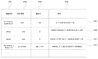
- FIG. 7 is an example of inspection formula information stored in the inspection formula storage unit 0116. Examples of four pieces of inspection formula information from 0705 to 0708 are shown. Each check expression information includes items of a start condition 0701, a condition type 0702, a connector 0703, and a 0704 condition.
- the activation condition 0701 defines under what conditions the inspection is performed. In the example of 0705, it is an example in which it is designated that the designated function “INJWCALC” is not executed.
- the file location specification “0701” such as “always” 0706, 0707 specified file “module1.c” specified line number “110” is performed.
- condition type 0702 designates “hold” 0705, 0706, 0707, or the safety condition “do not hold” 0708, ⁇ ⁇ ⁇ that the check expression always holds.
- the connector 0703 needs to be connected by some logical operator when connecting multiple check expressions, but these conditions include specifications that should always be satisfied, safety specifications that should not fall under those conditions, etc. There are different ways to integrate and connect them, so this is to specify them.
- Condition 0704 is a specific condition indicated by each inspection formula information.
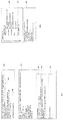
- FIG. 8 shows an output example of the inspection result output from the inspection device 0113.
- FIG. 8 (a) 801 shows an example of verification device activation and verification results when the CBMC described in Non-Patent Document 1 is used as the inspection device 0113.
- Reference numeral 801 denotes a command for starting the verifier.
- Reference numeral 803 denotes an output of the verifier, which indicates that all items to be verified were obtained as correct results.
- Fig. 8 (a) 804 shows the output result in which items verified by the verifier are explicitly displayed.
- 0805 is an example of the verification item, and 0805 is output that it has been proved that the value of the addition result of the variable “SINJW” and the variable “rinjw” is from 0 to 65535.
- Fig. 8 (b) shows an example of output when the example of 0808 inspector input software 0101 is verified by "frama-c" ⁇ ⁇ which is a verifier shown in Non-Patent Document 2 and Non-Patent Document 3.
- variable ⁇ ⁇ "INJW" can take a value between 0 and 10.
- the output of these inspection devices is displayed by the inspection result output unit 0114 from the screen of the verification support device or the input / output device 303 such as a printer.
- this output is input from the constraint equation input unit 0118 as an inspection condition for the next inspection unit, and integrated as a constraint integration unit 0117, thereby enabling inspection in a more limited inspection range, shortening the verification time, It is possible to verify more software on computer resources in the same verification environment.
- the test result of the test formula described in the software 0106 may be held in the RAM 305.
- the processing results executed during the driving of the vehicle can be held or output in units of functions, which can be used for specifying the cause when an error occurs.
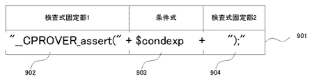
- FIG. 9 is an example in which an output character string used in step 411 of the check expression insertion unit 011 in FIG. Since the character string to be inserted depends on the specification of the checker 0113, it is necessary to convert it into a character string that becomes an appropriate check expression.
- FIG. 9 901 shows a generation pattern of an inspection formula character string suitable for the CBMC, which is a description example using a regular expression. By specifying the first fixed part first half 902, the variable part 903, and the second fixed part latter 904, and embedding the conditions in the variable part 903, a check expression description corresponding to the actually selected checker 0113 can be output.
- Non-patent document 4 discloses a combination of a fixed character string and a variable character string using such a regular expression.
Landscapes
- Engineering & Computer Science (AREA)
- Theoretical Computer Science (AREA)
- Quality & Reliability (AREA)
- Physics & Mathematics (AREA)
- General Engineering & Computer Science (AREA)
- General Physics & Mathematics (AREA)
- Computer Hardware Design (AREA)
- Debugging And Monitoring (AREA)
- Stored Programmes (AREA)
Abstract
本発明の目的は、大きなソフトウェアを小さな部分に分けて部分毎に検証し、その結果をシステム全体で組み合わせることを目的とし、部分毎の検証結果を統合しながら検証を進めることで検証範囲を限定し、規模の大きなソフトウェアへの網羅的検証を可能とすることである。 前記目的を実現するために、検査対象ソフトウェアの検査条件である要求仕様を第一の検査式として入力する検査式入力部と、検査部位抽出部により検証対象ソフトウェアを検査単位の部位毎に抽出し、検査式挿入部により検査対象に対し検査式を挿入し、前記検査対象ソフトウェアの網羅的検査を行う検査実行部と検査結果を出力する検査結果出力部と、検査結果を第二の制約式として入力する入力部と第一の制約式と第二の制約式を統合する統合部を備えることを特徴とする。
Description
本発明は、ソフトウェアを検証する検証システムおよびそのソフトウェアを搭載した制御装置に関する。
自動車エンジン制御などの制御装置として、中央演算装置、ROM、RAM、入出力信号処理装置などを内蔵したマイクロコントローラ(以下マイコンと表記)が用いられている。マイコンが実行するソフトウェアは制御対象が目的とする制御動作を行うように、一般的には制御処理を行うアプリケーションプログラムと入出力を行うデバイスドライバやオペレーティングシステム(OS)などによって構成されている(例えば、特許文献1参照)。
このような制御装置は、車両の制御を行うことで車両乗員の安全性に直接係る制御を行うことから、高い安全性を要求されている(例えば、特許文献2参照)。また、近年制御の高度化と規模の増大に伴い、安全に関わるシステムが第三者から見ても必要とされる高い安全性を満足する開発を行うためには、開発工程のうち検証工程において網羅率のより高い検証を求められており、安全に関わらないシステムと比べて、大きな開発工数を要することが課題となっている。
網羅的な検証を可能とする技術として、形式検証技術と呼ばれる技術が近年注目されている。形式検証技術は網羅的な検証が可能となる。
Edmund Clarke著 ANSI-C Bounded Model Checker User Manual 2006
frama-c Value Analysis http://frama-c.com/download/frama-c-value-analysis.pdf
Pascal Cuoq他著, Frama-C: A Software Analysis Perspective, in LNCS7504 Software Engineering and Formal Methods, p233
Jeffrey E.F. Friedl著, 詳説 正規表現, オライリージャパン
形式検証技術によれば網羅的な検証が可能となるものの、検証対象ソフトウェア規模が増大すると、検証に要する計算時間やメモリ、やディスクなどの計算資源が指数関数的に増大するため検証がし切れなくなるという、状態爆発と呼ばれる問題がある。このため、現実に用いられるソフトウェア全体を一度に検証することは現実的には実現できない。
大規模で形式検証適用が困難なソフトウェアを検証するためには、ソフトウェアを小さな検証単位に分割することと、探索範囲となる検証すべき条件を可能な限り限定することが有効である。
このため本発明の目的は、大きなソフトウェアを小さな部分に分けて部分毎に検証し、その結果をシステム全体で組み合わせ、部分毎の検証結果を統合しながら検証を進めることにある。
また、本発明の他の目的は、検証対象ソフトウェアに存在する条件だけでなく、設計情報としての条件を検証条件に与えることで検証範囲を限定し規模の大きなソフトウェアへの網羅的検証を可能とすることにある。
前記目的を実現するために、本発明のソフトウェア検証システムは、入出力に依存関係のある複数の機能を備えた制御プログラムのソースコードを入力し、前記制御プログラムを検証する検査実行部と、前記ソースコードを前記複数の機能単位で複数の検査部位に分割し抽出する検査部位抽出部と、前記複数の検査部位のうち一の検査部位に関する検査結果出力に基づき、連続する次の検査部位の検査範囲を規定する第1の制約式を作成する第1の制約式作成部と、を備え、前記第1の制約式に基づいて前記複数の検査部位を順に検査することを特徴とする。
上記構成にてソフトウェア検証装置を作成すると、大規模なソフトウェアを小さな単位で分割しながら、ひとつの検証部位の検証結果と設計者が与えた検証条件を次の検証部位に適用していくことにより、状態爆発を抑制しながら大規模なソフトウェアの検証が可能となる。
以下、図面を参照しながら本発明の実施形態について説明する。
(ハードウェア構成)
図1は本発明の実施形態のソフトウェア検証システムの構成を示す構成図である。検査装置(検査ツール)0102はソフトウェア0106を全体を検査することを目的としている。ここでいう検査とは、ソフトウェア0106のソースコードに挿入された検査式で定義される検証範囲内において、ソースコードが取り得る状態を網羅的に探索し、所望の状態になることを検証することをいう。
図1は本発明の実施形態のソフトウェア検証システムの構成を示す構成図である。検査装置(検査ツール)0102はソフトウェア0106を全体を検査することを目的としている。ここでいう検査とは、ソフトウェア0106のソースコードに挿入された検査式で定義される検証範囲内において、ソースコードが取り得る状態を網羅的に探索し、所望の状態になることを検証することをいう。
ソフトウェア0106は、例えば図3で後述するような、自動車を制御するコントロールユニットに搭載される制御ソフトウェアである。検査条件設定部0103では、まず検査部位抽出部0110により106から検査対象ソフトウェア0108を一定の検査単位でソフトウェア部品として抽出し、次に検査式挿入部0111により検査式を挿入する。
前記検査式は0108中で所定の処理を行う処理部の実行前または実行後に、事前事後条件判定部0107と、判定結果を出力する判定結果出力部0109として挿入する。上述した自動車を制御する制御ソフトウェアの例では、処理部(所定の入力値に対して出力値を演算する処理等)の実行前に、センサ値などの入力値の取り得る値(検証範囲)が事前条件として挿入される。また、事前条件で指定された入力値に対する処理部の出力値の取り得る値(設計値等)が事後条件として挿入される。
次に検査実行部0104は検査手段実行部0112により、前記検査式を挿入した前記ソフトウェア部品を検査器投入ソフトウェア0101として検査器0113を用いて網羅的に検証する。
検査結果出力部0114は検査器0113から得た検査結果をユーザ或いは出力装置に出力するとともに、要求仕様入力部0105に出力する。
要求仕様入力部0105は前記検査結果を制約式入力部0118を用いて第一の制約式として入力する。また検査式入力部0105はユーザから入力した検査式を前記検査式保持部0116に第2の制約式として保持する。制約統合部0117は前記第1の制約式と前記第2の制約式を統合し検査式挿入部に出力する。
なお、前記検査単位とはソフトウェアを構成する構成要素を示しており、C言語のひとつの関数が前記単位の一例であるが、その他の粒度に設定することも可能であり、この例に特定されるものではない。
図2は本発明を実現するためのシステム構成図である。計算機の演算装置などからなる処理装置301と、ディスク装置やメモリ装置からなる記憶装置302と、モニタ、キーボード、ネットワーク、プリンタなどからなる入出力装置303から構成される。処理装置301には、前記検査部位抽出部305,検査式挿入部306, 検査手段起動部307, 検査結果出力部308、検査式入力部309、制約統合部310,検査式入力部311が配置される。記憶装置には前記、ソフトウェア0106を格納するプログラムコード312、前記検査式保持部313、検査結果格納部314、検査対象ソフトウェア315が配置される。
図3は本発明の対象とする制御システムのひとつである自動車エンジン制御システムの構成を示すものである。
コントロールユニット301はマイクロコントローラ 302 (CPU)、信号入力回路309、アクチュエータ駆動回路 312、通信回路 311 から構成され、センサ1311、 センサ2 316から信号入力回路309を介して得た外界の情報に基づき、駆動回路310を介してアクチュエータ314を駆動することで制御を行う。また、一部の信号については通信回路311を介して通信線217から得た他の制御装置316からの入出力を用いて制御処理を行う。
前記マイクロコントローラ302は、入力回路 303、演算装置 304、揮発性読み書きメモリ305(RAM)、読み出し専用メモリ306(ROM)、割込み制御装置 307、メモリ保護装置 308、出力回路 309、通信制御装置 310、から構成される。
ソフトウェア0106は読み出し専用メモリ306に格納され、マイクロコントローラ302によって実行され、所定の制御処理を行う。
(ソフトウェアの処理詳細)
図4aに示すのが、検査部位抽出部の動作である。検査部位抽出部はプログラムコード格納部312からソフトウェア0106のプログラムコードの特定部位を抽出し部分的なプログラム構成要素を出力する部分である。まず抽出を開始する点である抽出始点を検索401し、次に抽出の終点を検索402する。始点から終点に相当するプログラムコードを検査部位として切り出し403、検査式生成部を呼出し404、検査部位として抽出したプログラムコード中に検査式を挿入する。全ての対象モジュールを抽出し終えたか否かを判定405し、全ての対象の抽出を終了していれば動作を終了405する。
図4aに示すのが、検査部位抽出部の動作である。検査部位抽出部はプログラムコード格納部312からソフトウェア0106のプログラムコードの特定部位を抽出し部分的なプログラム構成要素を出力する部分である。まず抽出を開始する点である抽出始点を検索401し、次に抽出の終点を検索402する。始点から終点に相当するプログラムコードを検査部位として切り出し403、検査式生成部を呼出し404、検査部位として抽出したプログラムコード中に検査式を挿入する。全ての対象モジュールを抽出し終えたか否かを判定405し、全ての対象の抽出を終了していれば動作を終了405する。
図4bに示すのが検査式生成部の動作である。検査式生成部は、プログラムコードあるいはプログラムコードの一分を入力し、検査式を挿入したプログラムコードを出力する部分である。検査式格納部313から条件式パターンをそれぞれ入力し、検査式情報を作成し制約統合部310へ格納することが目的である。処理が開始406されると、検査式格納部313から検査式を読み込み407、プログラムコード格納部312からプログラムコードを一行ずつ入力する407。読み込んだ部位が検査式を挿入すべき位置か判定する409。挿入部位に該当する場合には、検査式を抽出し410、検査式を生成する411。対象モジュールの読み込みが終端に達しているか判定し412、終端に達していれば終了413し、対象モジュール全体への検査式挿入判定と挿入が完了するまで繰り返す。
図5に示すのが検査器が検査する対象とする検査器投入ソフトウェア0101の例である。検査対象となる検査対象ソフトウェア0108の例が、図5(a)の関数501とその処理内容503、ならびに図5(b)関数505とその処理内容507である。502が事前・事後条件判定部0107の例であり、507によると、符号なし2バイト長の変数"ETH" はソースコードの情報のみからは、0以上65535以下の値を取り得る、と判断できるが、さらに設計上の情報を与えたことにより、0以上50以下の値のみを取り得る、という前提条件を課すことができる。
このように変数の取り得る値を限定することにより、検証時の探索範囲を削減することができ、前述の状態爆発を避けることが可能となる。同様に変数 "WTP" は0以上150以下の範囲であることを示している。504は関数501の処理内容503を実行後に満すべき条件を記述した事前・事後条件判定部0107の例である。実行後に変数SINJWが0以上150以下の範囲であることを検査条件として示している。
506は関数505に対する事前・事後条件判定部0107の例であり、502に加えて変数"SINJW"が0以上150以下であるという条件が追加されている。これは、504で検証した関数501の事後条件を関数505の事前条件として追加したものであり、関数501と関数505が、その呼出し元関数509から前後順に呼び出されている情報を用いることにより、関数501の次に続く関数505の条件を、関数501の検証結果と事前の設計情報である事前条件502を統合した条件として、制約統合部0117により統合された場合の例である。連続する検査対象の検査結果と設計情報として与えた条件を統合することにより、検査範囲をより限定できる。508は事前・事後条件判定部0107および判定結果出力部0109の例であり、検査を行い違反が見付かった場合にはその情報を出力する。この判定および結果出力は検証時に処理装置301上で実行し入出力装置303から結果を出力する実施形態と、制御装置301上のROM306に搭載するソフトウェアとして実装し、301上で実施し結果を通信線316を介し診断端末314あるいは制御装置315に出力する実施形態がある。自動車等の制御ソフトウェアでは、ある関数の出力結果を用いて続く関数が演算処理を行い、複数の関数が連続して処理を行って機器を制御する場合が多い。本発明では、このように入出力値に依存関係のある連続した関数において、前の関数の検証結果を続く関数の制約式として用いることにより、個々の関数の検証範囲を抑えつつも制御ソフトウェア全体を網羅的に検証することが出来る。
図6は制約統合部0117の処理手順である。検査対象ソフトウェアの検査式挿入位置に関する情報を入力する601。挿入位置に関する情報とは、ソフトウェアのソースコードを含むファイル名や行番号、関数などのモジュール名、その実行前、実行後などの具体的な位置を示す情報である。次に検査式格納部0116から第1の検査式を入力する602。次に制約式入力部0118から第2の検査式を入力する603。第2の検査式は、要求仕様入力部0105に入力された制御仕様等に基づいて設定されている。制御仕様としては、例えば自動車の制御ソフトウェアの場合、車両の取り得る状態遷移、車両の外界情報設定値、所定の車載機器が所定の条件で取るべき仕様等である。次に602、603によって入力した各々の検査式について検査式の種別を判定し604、この種別に基づき検査式同士の結合条件を決定する605。最後に605で決定した結合条件を表す条件結合子を用いて検査式を連結し、統合した制約式として出力する606。
図7は、検査式格納部0116に格納される検査式情報の例である。0705から0708まで4つの検査式情報の例を示している。各検査式情報は、起動条件0701、条件種別0702、結合子0703、0704条件の項目を含む。起動条件0701は、どのような条件で検査を行うかを定めたものであり、0705の例では指定した関数"INJWCALC" の実行前であることを指定した例である。この他に常に検査する"always" 0706, 0707指定したファイル "module1.c" の指定した行番号 "110"のようなファイル位置の指定 0701 を行う。条件種別0702は、その検査式が常に成り立つ "hold" 0705, 0706, 0707, あるいはその条件が成立してはならないという安全条件 "do not hold" 0708、 を指定する。結合子0703は、複数の検査式を連結する際には何らかの論理演算子で結合する必要があるが、それらの条件には、常に成立するべき仕様や、その条件に陥ってはならない安全仕様などがあり、これらを統合し連接するたには個別に異なるため、これを指定するためのものである。条件0704は、各検査式情報が示す具体的な条件である。
図8は検査器0113から出力された検査結果の出力例である。図8(a)801は検査器0113として、非特許文献1に記載のCBMCを利用した場合の検証器の起動および検証結果の例である。801は検証器を起動するコマンドである。803は検証器の出力であり、検証すべき項目が全て正しい結果であったことが得られたことを示している。
図8(a)804は検証器に検証した項目を明示的に表示させた出力結果である。0805はその検証項目の一例であり、そのうちの0805は変数 "SINJW" と 変数"rinjw" の加算結果の値が0以上65535以下であることが証明されたことが出力されている。
図8(b)は、0808の検査器投入ソフトウェア0101の例を、非特許文献2, 非特許文献3に示す検証器である "frama-c" で検証した際の出力例である。
検証の結果変数 "INJW" の取り得る値が0~10であることが示された様子を示している。
これらの検査器の出力は検査結果出力部0114により検証支援装置の画面やプリンタなどの入出力装置303から表示させる。また、この出力はつぎの検査単位の検査条件として制約式入力部0118から入力し、制約統合部0117として統合することで、より限定された検査範囲での検査を可能とし、検証時間の短縮や、同一検証環境の計算機資源においてより多くのソフトウェアの検証を可能とすることができる。
また、検査器の出力に代えて、コントロールユニット301によって、ソフトウェア0106を実行した時に、ソフトウェア0106に記述された検査式の検査結果をRAM305に保持するようにしてもよい。これにより、車両の運転中に実行された処理結果を機能単位で保持または出力出来て、エラーが生じた際の原因特定に役立てることが出来る。
図9は検査式挿入部011の処理フロー図4のステップ411、検査式生成の工程で使用する出力文字列を具体的に記載した例である。挿入する文字列は検査器0113の仕様に依存するため、適切な検査式となる文字列への変換が必要である。図9 901は前記CBMCに適した検査式文字列の生成パターンを示しており、正規表現を用いた記載例である。固定部前半902と可変部903、固定部後半904を指定し、条件を可変部903に埋め込むことにより実際に選択した検査器0113に対応した検査式記述を出力できる。このような正規表現を用いた固定文字列と可変文字列の組み合わせは非特許文献4に示されている。
(実施例による効果)
これにより、検証時の検証対象ソフトウェアを入出力値に依存関係のある複数の機能単位で分割し、探索範囲である検証条件を限定することが可能となり、より大規模なソフトウェアに対し、網羅的検証が可能となる。
これにより、検証時の検証対象ソフトウェアを入出力値に依存関係のある複数の機能単位で分割し、探索範囲である検証条件を限定することが可能となり、より大規模なソフトウェアに対し、網羅的検証が可能となる。
0102・・・検査装置、0103・・・検査条件設定部、0104・・・検査実行部、0105・・・要求仕様入力部、0106・・・ソフトウェア、0108・・・検査対象ソフトウェア
Claims (6)
- 入出力に依存関係のある複数の機能を備えた制御プログラムのソースコードを入力し、前記制御プログラムを検証する検査実行部と、
前記ソースコードを前記複数の機能単位で複数の検査部位に分割し抽出する検査部位抽出部と、
前記複数の検査部位のうち一の検査部位に関する検査結果出力に基づき、連続する次の検査部位の検査範囲を規定する第1の制約式を作成する第1の制約式作成部と、を備え、
前記第1の制約式に基づいて前記複数の検査部位を順に検査することを特徴とするソフトウェア検証システム - 請求項1に記載のソフトウェア検証システムにおいて、
制御対象機器の取り得る状態遷移、制御対象機器の外界情報設定値、制御仕様の少なくとも1つに基づいて、検査部位の検査範囲を規定する第2の制約式を作成する第2の制約式作成部を備え、
第1の制約式と第2の制約式とに基づいて前記複数の検査部位を順に検査することを特徴とするソフトウェア検証システム。 - 請求項2に記載のソフウェア検証システムであって、
前記検査部位抽出手段はC言語で記述されたソフトウェアのソースコードを対象とし、関数を単位として抽出することを特徴とするソフトウェア検証システム。 - 請求項2に記載のソフウェア検証システムであって、
検査対象処理記述と事前条件と事後条件のうち少なくともひとつを入力として、前記複数の検査部位を順に検査することを特徴とするソフトウェア検証システム - 請求項2に記載のソフウェア検証システムであって、
前記第1の制約式と前記第2の制約式を統合する制約式統合部を備えることを特徴とするソフトウェア検証システム。 - センサおよびアクチュエータに接続され、
前記センサの入力をもとに制御演算を行いアクチュエータへ出力する制御装置において、
請求項1に記載の制御ソフトウェアを実行し、前記検査式による検査結果を保持または出力する制御装置。
Applications Claiming Priority (2)
| Application Number | Priority Date | Filing Date | Title |
|---|---|---|---|
| JP2014-153420 | 2014-07-29 | ||
| JP2014153420A JP6248008B2 (ja) | 2014-07-29 | 2014-07-29 | ソフトウェア検証システムおよび制御装置 |
Publications (1)
| Publication Number | Publication Date |
|---|---|
| WO2016017560A1 true WO2016017560A1 (ja) | 2016-02-04 |
Family
ID=55217461
Family Applications (1)
| Application Number | Title | Priority Date | Filing Date |
|---|---|---|---|
| PCT/JP2015/071185 Ceased WO2016017560A1 (ja) | 2014-07-29 | 2015-07-27 | ソフトウェア検証システムおよび制御装置 |
Country Status (2)
| Country | Link |
|---|---|
| JP (1) | JP6248008B2 (ja) |
| WO (1) | WO2016017560A1 (ja) |
Cited By (2)
| Publication number | Priority date | Publication date | Assignee | Title |
|---|---|---|---|---|
| WO2018198783A1 (ja) * | 2017-04-27 | 2018-11-01 | 日立オートモティブシステムズ株式会社 | 車両制御システム検証手法および検証装置および制御装置 |
| CN108733557A (zh) * | 2018-03-28 | 2018-11-02 | 新华三信息安全技术有限公司 | 一种测试点生成方法及装置 |
Families Citing this family (2)
| Publication number | Priority date | Publication date | Assignee | Title |
|---|---|---|---|---|
| JP6567212B2 (ja) | 2017-02-22 | 2019-08-28 | 三菱電機株式会社 | 等価性検証装置および等価性検証プログラム |
| WO2021214843A1 (ja) * | 2020-04-20 | 2021-10-28 | 三菱電機株式会社 | 動作確認支援装置、動作確認支援方法及び動作確認支援プログラム |
Citations (2)
| Publication number | Priority date | Publication date | Assignee | Title |
|---|---|---|---|---|
| JP2010218148A (ja) * | 2009-03-16 | 2010-09-30 | Toshiba Corp | 事前条件生成装置および事後条件生成装置、ならびにこれらの方法 |
| WO2011052030A1 (ja) * | 2009-10-26 | 2011-05-05 | 株式会社 東芝 | 事前条件生成装置 |
Family Cites Families (1)
| Publication number | Priority date | Publication date | Assignee | Title |
|---|---|---|---|---|
| JP4905173B2 (ja) * | 2007-02-16 | 2012-03-28 | 日本電気株式会社 | ソフトウェア検証装置、ソフトウェア検証方法およびソフトウェア検証プログラム |
-
2014
- 2014-07-29 JP JP2014153420A patent/JP6248008B2/ja active Active
-
2015
- 2015-07-27 WO PCT/JP2015/071185 patent/WO2016017560A1/ja not_active Ceased
Patent Citations (2)
| Publication number | Priority date | Publication date | Assignee | Title |
|---|---|---|---|---|
| JP2010218148A (ja) * | 2009-03-16 | 2010-09-30 | Toshiba Corp | 事前条件生成装置および事後条件生成装置、ならびにこれらの方法 |
| WO2011052030A1 (ja) * | 2009-10-26 | 2011-05-05 | 株式会社 東芝 | 事前条件生成装置 |
Cited By (4)
| Publication number | Priority date | Publication date | Assignee | Title |
|---|---|---|---|---|
| WO2018198783A1 (ja) * | 2017-04-27 | 2018-11-01 | 日立オートモティブシステムズ株式会社 | 車両制御システム検証手法および検証装置および制御装置 |
| JP2018185244A (ja) * | 2017-04-27 | 2018-11-22 | 日立オートモティブシステムズ株式会社 | 車両制御システム検証手法および検証装置および制御装置 |
| US11372442B2 (en) | 2017-04-27 | 2022-06-28 | Hitachi Astemo, Ltd. | Vehicle control system validation technique and validation device, and control device |
| CN108733557A (zh) * | 2018-03-28 | 2018-11-02 | 新华三信息安全技术有限公司 | 一种测试点生成方法及装置 |
Also Published As
| Publication number | Publication date |
|---|---|
| JP2016031622A (ja) | 2016-03-07 |
| JP6248008B2 (ja) | 2017-12-13 |
Similar Documents
| Publication | Publication Date | Title |
|---|---|---|
| JP5412510B2 (ja) | 1個のソフトウェアの少なくとも一部を検証するためにテストケースを自動的に形成する方法 | |
| CN106528100B (zh) | 用于安全关键软件开发的基于模型的技术和过程的系统和方法 | |
| US8589892B2 (en) | Verification of speculative execution | |
| CN103279418B (zh) | 一种组态控制信息的测试方法和装置 | |
| JP2006024006A (ja) | テストケース生成装置、テストケース生成プログラム、モデルベース開発プログラム、ソースコード生成妥当性診断装置、ソースコード生成妥当性診断プログラム、およびモデルベース開発方法。 | |
| WO2009047430A2 (fr) | Procédé de génération automatique de script pour tester la validité d'un logiciel de fonctionnement d'un système embarqué à bord d'un aéronef, et dispositif de mise en oeuvre | |
| US20100333061A1 (en) | Explicit state model checking of sl/sf models using the auto-generated code | |
| JP2014203314A (ja) | Ecuシミュレーション装置 | |
| EP4404066A1 (en) | Automated test generation | |
| US10592703B1 (en) | Method and system for processing verification tests for testing a design under test | |
| JP6248008B2 (ja) | ソフトウェア検証システムおよび制御装置 | |
| CN106155903B (zh) | 用于系统设计验证的装置和方法 | |
| JP6142705B2 (ja) | オブジェクト指向言語のための記号テストドライバの反復生成 | |
| CN115562931B (zh) | 处理器调试模块验证方法、装置、电子设备和存储介质 | |
| WO2019142266A1 (ja) | テストケース生成装置、テストケース生成方法およびテストケース生成プログラム | |
| JP2009211503A (ja) | ソースコード検証装置、及びソースコード検証方法 | |
| US20240231347A1 (en) | Fault injection test method and apparatus, and fault injection method | |
| Jaffuel et al. | LEIRIOS test generator: Automated test generation from B models | |
| JP6139670B2 (ja) | 制御システム検査装置 | |
| JP2015123748A (ja) | 検査システム | |
| JPWO2020194455A1 (ja) | テストケース生成装置、テストケース生成方法、およびテストケース生成プログラム | |
| JP6169302B2 (ja) | 仕様構成装置および方法 | |
| CN115168131B (zh) | 一种故障注入的cpu异常功能验证方法 | |
| US11200069B1 (en) | Systems and methods for generating a software application | |
| US8930759B2 (en) | Stream generation |
Legal Events
| Date | Code | Title | Description |
|---|---|---|---|
| 121 | Ep: the epo has been informed by wipo that ep was designated in this application |
Ref document number: 15828147 Country of ref document: EP Kind code of ref document: A1 |
|
| NENP | Non-entry into the national phase |
Ref country code: DE |
|
| 122 | Ep: pct application non-entry in european phase |
Ref document number: 15828147 Country of ref document: EP Kind code of ref document: A1 |