WO2016010045A1 - 電解用陰極及び電解用陰極の製造方法 - Google Patents
電解用陰極及び電解用陰極の製造方法 Download PDFInfo
- Publication number
- WO2016010045A1 WO2016010045A1 PCT/JP2015/070185 JP2015070185W WO2016010045A1 WO 2016010045 A1 WO2016010045 A1 WO 2016010045A1 JP 2015070185 W JP2015070185 W JP 2015070185W WO 2016010045 A1 WO2016010045 A1 WO 2016010045A1
- Authority
- WO
- WIPO (PCT)
- Prior art keywords
- cathode
- substrate
- coating solution
- cathode catalyst
- catalyst layer
- Prior art date
Links
Images


Classifications
-
- C—CHEMISTRY; METALLURGY
- C25—ELECTROLYTIC OR ELECTROPHORETIC PROCESSES; APPARATUS THEREFOR
- C25B—ELECTROLYTIC OR ELECTROPHORETIC PROCESSES FOR THE PRODUCTION OF COMPOUNDS OR NON-METALS; APPARATUS THEREFOR
- C25B11/00—Electrodes; Manufacture thereof not otherwise provided for
- C25B11/02—Electrodes; Manufacture thereof not otherwise provided for characterised by shape or form
- C25B11/03—Electrodes; Manufacture thereof not otherwise provided for characterised by shape or form perforated or foraminous
-
- B—PERFORMING OPERATIONS; TRANSPORTING
- B01—PHYSICAL OR CHEMICAL PROCESSES OR APPARATUS IN GENERAL
- B01J—CHEMICAL OR PHYSICAL PROCESSES, e.g. CATALYSIS OR COLLOID CHEMISTRY; THEIR RELEVANT APPARATUS
- B01J23/00—Catalysts comprising metals or metal oxides or hydroxides, not provided for in group B01J21/00
- B01J23/38—Catalysts comprising metals or metal oxides or hydroxides, not provided for in group B01J21/00 of noble metals
- B01J23/40—Catalysts comprising metals or metal oxides or hydroxides, not provided for in group B01J21/00 of noble metals of the platinum group metals
-
- B—PERFORMING OPERATIONS; TRANSPORTING
- B01—PHYSICAL OR CHEMICAL PROCESSES OR APPARATUS IN GENERAL
- B01J—CHEMICAL OR PHYSICAL PROCESSES, e.g. CATALYSIS OR COLLOID CHEMISTRY; THEIR RELEVANT APPARATUS
- B01J23/00—Catalysts comprising metals or metal oxides or hydroxides, not provided for in group B01J21/00
- B01J23/70—Catalysts comprising metals or metal oxides or hydroxides, not provided for in group B01J21/00 of the iron group metals or copper
- B01J23/74—Iron group metals
- B01J23/755—Nickel
-
- B—PERFORMING OPERATIONS; TRANSPORTING
- B05—SPRAYING OR ATOMISING IN GENERAL; APPLYING FLUENT MATERIALS TO SURFACES, IN GENERAL
- B05D—PROCESSES FOR APPLYING FLUENT MATERIALS TO SURFACES, IN GENERAL
- B05D3/00—Pretreatment of surfaces to which liquids or other fluent materials are to be applied; After-treatment of applied coatings, e.g. intermediate treating of an applied coating preparatory to subsequent applications of liquids or other fluent materials
- B05D3/02—Pretreatment of surfaces to which liquids or other fluent materials are to be applied; After-treatment of applied coatings, e.g. intermediate treating of an applied coating preparatory to subsequent applications of liquids or other fluent materials by baking
- B05D3/0254—After-treatment
-
- C—CHEMISTRY; METALLURGY
- C25—ELECTROLYTIC OR ELECTROPHORETIC PROCESSES; APPARATUS THEREFOR
- C25B—ELECTROLYTIC OR ELECTROPHORETIC PROCESSES FOR THE PRODUCTION OF COMPOUNDS OR NON-METALS; APPARATUS THEREFOR
- C25B11/00—Electrodes; Manufacture thereof not otherwise provided for
- C25B11/04—Electrodes; Manufacture thereof not otherwise provided for characterised by the material
- C25B11/051—Electrodes formed of electrocatalysts on a substrate or carrier
- C25B11/055—Electrodes formed of electrocatalysts on a substrate or carrier characterised by the substrate or carrier material
- C25B11/057—Electrodes formed of electrocatalysts on a substrate or carrier characterised by the substrate or carrier material consisting of a single element or compound
-
- C—CHEMISTRY; METALLURGY
- C25—ELECTROLYTIC OR ELECTROPHORETIC PROCESSES; APPARATUS THEREFOR
- C25B—ELECTROLYTIC OR ELECTROPHORETIC PROCESSES FOR THE PRODUCTION OF COMPOUNDS OR NON-METALS; APPARATUS THEREFOR
- C25B11/00—Electrodes; Manufacture thereof not otherwise provided for
- C25B11/04—Electrodes; Manufacture thereof not otherwise provided for characterised by the material
- C25B11/051—Electrodes formed of electrocatalysts on a substrate or carrier
- C25B11/073—Electrodes formed of electrocatalysts on a substrate or carrier characterised by the electrocatalyst material
- C25B11/075—Electrodes formed of electrocatalysts on a substrate or carrier characterised by the electrocatalyst material consisting of a single catalytic element or catalytic compound
- C25B11/081—Electrodes formed of electrocatalysts on a substrate or carrier characterised by the electrocatalyst material consisting of a single catalytic element or catalytic compound the element being a noble metal
-
- C—CHEMISTRY; METALLURGY
- C25—ELECTROLYTIC OR ELECTROPHORETIC PROCESSES; APPARATUS THEREFOR
- C25B—ELECTROLYTIC OR ELECTROPHORETIC PROCESSES FOR THE PRODUCTION OF COMPOUNDS OR NON-METALS; APPARATUS THEREFOR
- C25B11/00—Electrodes; Manufacture thereof not otherwise provided for
- C25B11/04—Electrodes; Manufacture thereof not otherwise provided for characterised by the material
- C25B11/051—Electrodes formed of electrocatalysts on a substrate or carrier
- C25B11/073—Electrodes formed of electrocatalysts on a substrate or carrier characterised by the electrocatalyst material
- C25B11/091—Electrodes formed of electrocatalysts on a substrate or carrier characterised by the electrocatalyst material consisting of at least one catalytic element and at least one catalytic compound; consisting of two or more catalytic elements or catalytic compounds
- C25B11/093—Electrodes formed of electrocatalysts on a substrate or carrier characterised by the electrocatalyst material consisting of at least one catalytic element and at least one catalytic compound; consisting of two or more catalytic elements or catalytic compounds at least one noble metal or noble metal oxide and at least one non-noble metal oxide
-
- C—CHEMISTRY; METALLURGY
- C25—ELECTROLYTIC OR ELECTROPHORETIC PROCESSES; APPARATUS THEREFOR
- C25B—ELECTROLYTIC OR ELECTROPHORETIC PROCESSES FOR THE PRODUCTION OF COMPOUNDS OR NON-METALS; APPARATUS THEREFOR
- C25B11/00—Electrodes; Manufacture thereof not otherwise provided for
- C25B11/04—Electrodes; Manufacture thereof not otherwise provided for characterised by the material
- C25B11/051—Electrodes formed of electrocatalysts on a substrate or carrier
- C25B11/055—Electrodes formed of electrocatalysts on a substrate or carrier characterised by the substrate or carrier material
- C25B11/057—Electrodes formed of electrocatalysts on a substrate or carrier characterised by the substrate or carrier material consisting of a single element or compound
- C25B11/061—Metal or alloy
Definitions
- the present invention members of a wire mesh, expanded metal, punching metal or similar shape, which are used as cathodes of electrolysis cells of various industrial electrolysis involving soda electrolysis, water electrolysis, oxygen generation or chlorine generation, intersect each other
- the present invention relates to a cathode for electrolysis, in which a cathode catalyst layer is formed on a conductive cathode substrate in a form having a large number of intersections, and a method of manufacturing the cathode for electrolysis.
- an ion exchange membrane alkaline chloride electrolysis cell for producing an alkali metal hydroxide having high current efficiency and low voltage and high purity, in particular, an anode for electrolysis with an ion exchange membrane sandwiched therebetween.
- a large number of filter press type zero gap electrolysis cells or finite electrolysis cells are used, in which the electrolyte cathode and the cathode for electrolysis are in contact with each other.
- the conductive cathode substrate may be a metal mesh, expanded metal, punching metal or the like.
- a conductive cathode substrate having a shape in which members have crossed each other hereinafter referred to simply as a “conductive cathode substrate having a large number of intersections” or “a wire netlike cathode substrate (Also called ')' is used.
- a cathode catalyst layer is actively formed on one surface of the conductive cathode substrate having a large number of intersections by using a coating method, and the cathode is manufactured and formed (the cathode catalyst layer side Is used in a state of being placed in contact with or on a minute space on one side of the ion exchange membrane.
- an anode for electrolysis is disposed in contact with or in a minute space.
- nickel or nickel alloy is used as a base of the cathode, and the base of the cathode is used a conductive cathode base having a large number of intersections as described above. It is practiced to form a cathode catalyst layer containing a cathode catalyst component which is a rare metal such as expensive platinum on at least one surface of these substrates.
- Patent Document 1 discloses a large number of crossings when used for the anode and the cathode. Thickness, aperture ratio, thickness of cathode catalyst layer, thickness of irregularities on cathode surface, annealing, shaping, flattening by rolling, surface roughening by blasting, cleaning with acid And etching treatment, corrosion resistance improvement treatment and the like.
- the conductive substrate having a large number of intersections is generally annealed, shaped, flattened by rolling, roughened by blast, A pretreatment such as acid cleaning, etching treatment, corrosion resistance improvement treatment, etc. is applied, and then, on one side, a cathode catalyst layer containing a cathode catalyst component comprising a platinum group metal and / or its oxide is formed. Has been done.
- the step of forming the cathode catalyst layer is called an activation treatment step, and the step generally uses a coating solution containing a starting material (hereinafter, also simply referred to as a starting material) that can be a cathode catalyst component.
- a coating solution containing a starting material hereinafter, also simply referred to as a starting material
- the coating solution applied to the substrate is dried and fired. More specifically, in the activation treatment step, usually, first, a coating solution in which starting materials are dissolved is prepared, and the coating solution is subjected to the pretreatment as described above for a conductive substrate having a large number of holes. It is applied to one side, dried, and fired to form a cathode catalyst layer.
- the coating solution is applied until the cathode catalyst component adhering to the front side of the conductive cathode substrate reaches a desired amount, and the coating solution is applied to the substrate
- the steps of drying and firing are repeated a plurality of times, and through these application, drying and firing steps, a cathode catalyst layer containing a cathode catalyst component (catalyst layer forming substance) which is a rare metal such as expensive platinum is formed.
- the thing is done.
- coats a coating liquid to a base material is normally performed by the roller, spray, brush coating, electrostatic coating, and other methods. Further, heating in the firing step is usually performed by an electric furnace or the like.
- Patent No. 4453973 gazette
- the present inventor considers means for reducing or saving the catalyst layer on the substrate without impairing the cathode performance in view of the fact that the cathode catalyst component is a very expensive rare metal such as platinum. did. Then, from such a point of view, in particular, a coating solution containing a starting material of the cathode catalyst component is applied to the front side of the conductive cathode substrate, and the coating solution applied thereafter is dried and fired. The formation process of the cathode catalyst layer containing the cathode catalyst component on the front side and the back side of the substrate was examined in detail. As a result, the following findings were obtained.
- the present inventor has found that when a coating solution is deposited on a conductive cathode substrate having a form of having many intersections where members cross each other, such as wire mesh, the numerous acute angle or right angle intersections If the generation of liquid pooling in a part could be prevented or suppressed, it was possible to reduce the amount of use of the expensive cathode catalyst component, and it came to be recognized that the economic effect was extremely large.
- the cathode catalyst layer is apt to be deposited as a “nickel layer” in the cathode catalyst layer, as a nickel component of nickel or a nickel alloy used as the conductive cathode substrate.
- the "nickel layer" deposited in the catalyst layer makes it easy to peel off when used as an electrode, and as a result, the consumption amount of the expensive cathode catalyst forming the cathode catalyst layer was found to contribute to the deterioration of electrode durability.
- the above fact is considered to be found because the nickel or nickel alloy used as an electrode substrate is dissolved and corroded by the coating solution when the coating solution is acidic, and this phenomenon is particularly remarkable. If this problem can be solved, not only the durability of the electrode can be improved, but also the usability of the cathode catalyst layer coating solution can be enhanced, which is extremely effective industrially.
- a cathode catalyst component of a cathode for electrolysis a rare earth element such as lanthanum, cerium, yttrium or praseodymium is used together with a noble metal such as platinum, iridium, ruthenium, palladium or osmium. All the ingredients are rare and extremely expensive materials called rare metals and precious metals, and their prices are rising year by year. And the above-mentioned electrolysis cell is used for large-scale facilities, such as being used for an electrolysis facility of a large scale chemical factory in a seaside area, and the amount of use of a cathode catalyst component is also huge.
- the ratio of the cost occupied by the cathode catalyst component in is extremely large. For this reason, it is no exaggeration to say that the reduction of the cost for the above-mentioned expensive cathode catalyst component, which is a material for forming the cathode catalyst layer, is a sad desire of the industry using the electrolytic cell. Specifically, the ability to form a catalyst layer with as small amount of cathode catalyst component as possible, and further enabling the formed catalyst layer to be used for a longer period, has a very significant industrial significance.
- the cathode catalyst layer is formed using a coating method on a conductive base material such as wire mesh, expanded metal, punching metal or the like having a large number of intersections as recognized by the inventor.
- a conductive base material such as wire mesh, expanded metal, punching metal or the like having a large number of intersections as recognized by the inventor.
- the occurrence of liquid pooling at a large number of intersections and the formation of a liquid pool cause a portion in which the cathode catalyst component not contributing to the performance improvement of the cathode catalyst layer is excessively fixed at many intersections.
- the “nickel layer” deposited in the catalyst layer makes it easy to peel off the catalyst layer itself, and the consumption amount of the cathode catalyst increases, resulting in durability There was no awareness of what was causing the loss.
- an object of the present invention is to apply a coating solution containing a cathode catalyst component on the front side and the back side of the conductive cathode substrate on the surface of the conductive cathode substrate having a large number of intersections using the coating method described above.
- An object of the present invention is to effectively prevent or suppress the occurrence of liquid pooling at the multiple acute angles or right angle intersections when applied, thereby reducing the amount of expensive cathode catalyst components used.
- the object of the present invention is to reduce the use amount of a cathode catalyst component comprising a rare metal such as a noble metal without reducing the cathode performance when forming the cathode catalyst layer, and to use the catalyst layer at the time of use It is an object of the present invention to provide a cathode for electrolysis and a manufacturing method of the cathode for electrolysis, which solves the problem of peeling of
- a coating solution containing the starting material of the cathode catalyst component was applied to the front surface of the conductive cathode substrate and the conductive cathode substrate made of either expanded metal or punching metal having the intersection of A cathode catalyst layer containing the cathode catalyst component formed on the front side and the back side of the conductive cathode substrate using a coating method of drying and baking a coating solution, the cathode catalyst component comprising platinum, And at least one selected from iridium, ruthenium, palladium, osmium, nickel, and oxides thereof, wherein the conductive cathode substrate is nickel or a nickel alloy, and the conductive negative electrode.
- the solidified portion of the liquid pool is not recognized at the intersection of the substrate, or if it is recognized, the cross-sectional shape of the solidified portion has a network-like pore, and the average porosity of the solidified portion is 15%
- the cathode for electrolysis characterized by the above is provided.
- the pores of the cross section of the solidified portion in the cross section of the conductive cathode substrate may not be recognized, or the cross section of the solidified portion is reticulated. And the average porosity of the solidified portion is at least 15%.
- the conductive cathode substrate immediately before applying the coating solution is preheated to a temperature of 43 ° C. to 120 ° C.
- the cathode catalyst is achieved by forming the cathode catalyst layer, but at the same time, the cathode catalyst may possibly be generated by being deposited as a "nickel layer” by elution of nickel from the substrate into the cathode catalyst layer. The effect of preventing the problem of layer peeling is also obtained.
- the above-mentioned average porosity is 44% or more.
- regulated in this application is an arithmetic mean value of the porosity measured by the method mentioned later.
- a method of manufacturing any of the cathodes for electrolysis described above, wherein a large number of crossing portions where linear or strip members cross each other is used.
- a cathode catalyst component is formed on at least one surface of a metal mesh having intersections, an expanded metal having multiple intersections having crossings at right angles or acute angles of the holes as intersections, or punching metal. Applying a coating solution containing the starting material, and drying and calcinating the coating solution applied to the base material one or more times to conduct the cathode catalyst layer containing the cathode catalyst component as the conductive material.
- the cathode catalyst component comprising platinum, iridium, ruthenium, palladium, osmium, nickel and oxides thereof
- the conductive cathode substrate is nickel or a nickel alloy, and the conductive cathode substrate immediately before applying the coating solution one or more times in the cathode catalyst layer forming step.
- the present invention provides a method of producing a cathode for electrolysis, comprising heating so that the temperature is in the range of 43 ° C to 120 ° C.
- a means for preheating the conductive cathode substrate is provided on the upstream side of the step of applying the coating solution.
- the step of applying the coating solution and thereafter drying and baking the coating solution applied to the substrate is repeated a plurality of times, and immediately before applying the coating solution using the means for preheating all the number of times to repeat. Heating the temperature of the conductive cathode substrate to be in the range of 43 ° C. to 120 ° C .; and setting the temperature of the conductive cathode substrate immediately before applying the coating solution in the temperature range of 43 ° C. to 63 ° C. And heating the coating solution to be acidic.
- the temperature of the conductive cathode substrate immediately before defined above is 43 ° C., which is the actually measured lower limit value when the effect of the present invention is remarkably recognized in the verification test, for example, 63 ° C. Means the temperature measured with an error of ⁇ 1 ° C.
- the step of forming the cathode catalyst layer immediately before applying the coating solution at the time of applying the coating solution containing the cathode catalyst component at one or more times, preferably all times when coating is repeated.
- the amount of expensive cathode catalyst component used to form the cathode catalyst layer can be reduced.
- a conductive cathode substrate is coated with a coating solution containing a cathode catalyst component using a coating method on the surface of a conductive cathode substrate having a large number of intersections such as wire mesh.
- a coating solution containing a cathode catalyst component using a coating method on the surface of a conductive cathode substrate having a large number of intersections such as wire mesh.
- the cathode catalyst layer formed by an extremely simple means of heating so that the temperature of the conductive cathode substrate immediately before applying the coating solution falls within a specific range.
- the porosity is measured using the form of the cross section of the cross section where the cathode catalyst component is excessively fixed (hereinafter also referred to as “solidified portion of liquid pool”) and the image processing software for binarization processing It is a figure which shows the state of.
- the form of the cross section of “solidified portion of liquid pool” in Example 3-3 and Example 3-4, in which the temperature of the wire mesh base immediately before applying the coating liquid is 63 ° C. using the low concentration coating liquid FIG.
- FIG. 8 is a diagram showing a state when the porosity of “solidified portion of liquid pool” is measured using the image processing software for binarization processing.
- FIG. 8 is a diagram showing a state when the porosity of “solidified portion of liquid pool” is measured using the image processing software for binarization processing.
- the temperature of the wire mesh substrate just before applying the coating solution was changed between ambient temperature and 63 ° C. under the condition of using a low concentration coating solution of 100 g / L. And it is a graph which shows correlation of a substrate temperature and a porosity obtained by carrying out statistical analysis of the data of the porosity of eight pieces each obtained by comparative example 1, and carrying out statistical analysis.
- the temperature of the wire mesh substrate just before applying the coating solution was changed between ambient temperature and 63 ° C.
- Example 2 under the condition of using a high concentration coating solution of 200 g / L, Example 2, 4 And it is a graph which shows correlation of a substrate temperature and a porosity obtained by carrying out statistical analysis of the data of the porosity of eight pieces each obtained by comparative example 2, and carrying out statistical analysis.
- the cathode for electrolysis according to an example of the present invention manufactured by heating the conductive cathode substrate so that the temperature of the conductive cathode substrate immediately before applying the coating liquid is 43 ° C. by applying the method of the present invention
- FIG. 6 is a view of a SEM photograph of a cut surface of the cathode catalyst layer before electrolysis.
- the cathode catalyst layer before electrolysis in the comparative cathode for electrolysis manufactured at a normal temperature (ambient temperature) with the temperature of the conductive cathode substrate just before applying the coating solution without applying the method of the present invention It is a figure of the SEM photograph of the cut surface of a cross section. The temperature of the conductive cathode substrate immediately before applying the coating solution was kept at normal temperature (ambient temperature) without applying the method of the present invention in the comparative cathode for electrolysis after the electrolysis shown in Table 5 It is a figure of the SEM photograph of the cut surface of a cathode catalyst layer.
- a conductive cathode substrate made of nickel or a nickel alloy is provided with a cathode catalyst layer formed by applying, drying and solidifying a coating solution containing a material for the cathode catalyst component, in the cathode catalyst layer
- the cathode which does not produce an excess and waste cathode catalyst layer ("solidified portion of liquid pool") at the intersection where the members of the cathode substrate intersect or which is excessively fixed compared to the conventional one
- the manufacturing method of the cathode for electrolysis of the present invention which can easily obtain the cathode for electrolysis of the present invention which achieves reduction of the amount of use of the expensive cathode catalyst component which can reduce the amount of the catalyst component will be described.
- the present invention is generated when the cathode catalyst layer is formed on at least one surface of the conductive cathode substrate having a form having a large number of intersections using a coating method.
- the purpose is to solve the newly found technical issues.
- the technical subject described above is a raw material of the cathode catalyst component all the times when application of the coating liquid is repeated once or more preferably.
- Solution is realized by the new configuration in which the temperature of the conductive cathode substrate immediately before the application of the coating solution containing the above is within the range of 43.degree. C. to 120.degree. C., and the above-mentioned remarkable effects are realized. . Therefore, the manufacturing method of the present invention is basically the same as the conventional manufacturing method of the cathode for electrolysis except for the above-mentioned constitution.
- the inventor of the present invention applies, dries and solidifies a coating liquid containing starting materials such as noble metals, oxides thereof and nickel oxides on the surface of a cathode substrate of nickel or nickel alloy.
- starting materials such as noble metals, oxides thereof and nickel oxides
- the nickel component tends to be deposited as a "nickel layer" in the cathode catalyst layer.
- the cathode catalyst layer is formed by the "coating thermal decomposition method" of applying, drying, and solidifying a coating solution, which constitutes the present invention
- the nickel component in the cathode substrate dissolves out and nickel is contained in the cathode catalyst layer.
- the nickel precipitates may be deposited as precipitates, and the nickel precipitates form a nickel layer through the firing process.
- the nickel layer is present in the cathode catalyst layer of the cathode, the nickel layer is acceleratedly eluted into the electrolyte by long-term electrolysis or short-time reverse electrolysis, and the cathode catalyst layer is peeled off.
- the production method of the present invention suppresses the appearance of the above-mentioned "nickel layer".
- the inventors of the present invention can accelerate the evaporation of the coating solution by heating the substrate in a specific temperature range immediately before the application of the coating solution, and as a result, the drying of the coating solution on the cathode substrate By speeding up, the contact time between the acidic coating solution and the substrate can be shortened, and as a result, it is effective that the nickel component of the cathode substrate is deposited as a "nickel layer" in the cathode catalyst layer.
- a coating solution in which the starting materials of catalyst components such as noble metals or noble metal oxides and nickel oxides are uniformly dissolved.
- chlorides, sulfates, and nitrates are used, and as the solvent, an acidic solvent such as hydrochloric acid, sulfuric acid, nitric acid is often used, and the coating liquid is often acidic.
- a cathode catalyst layer is formed using a coating solution containing starting materials such as noble metals, oxides thereof, nickel oxides, etc. on the surface of a cathode substrate of nickel or nickel alloy.
- Cathode catalyst which is particularly noticeable when using an acidic coating solution when forming a negative electrode, which is likely to deposit a nickel layer in the negative electrode catalyst layer by long-term electrolysis or short-time reverse electrolysis. It is possible to solve the problem that the amount of exhaustion of the cathode catalyst caused by peeling off the layer increases.
- a conductive cathode substrate having a form to be a subject of the technical problems of the present invention will be described.
- the conductive cathode substrate In the present invention, nickel or a nickel alloy is used as the conductive cathode substrate.
- the conductive cathode substrate (hereinafter also referred to as “conductive substrate”) has a form having a wire mesh, an expanded metal, a punching metal, or a similar shape, having a large number of intersections where members cross each other. It is a thing. The reason is that, in the present invention, the following points are the technical problems to be solved. That is, when the coating solution containing the cathode catalyst component is applied to the conductive cathode substrate, for example, a liquid pool is generated at the intersection where the members such as linear metal constituting the wire net intersect with each other.
- this “solidified portion of the liquid pool” has no meaning of contributing to the improvement of the cathode performance, and rather, it has been found in the present invention that the expensive material has become a waste.
- the purpose is to reduce the "solidified portion of the liquid pool" as much as possible.
- the crossing portion in the present invention is, for example, a portion where members such as linear or belt-like metal members forming a metal mesh cross, a right angle or an acute angle portion of a hole in expanded metal, punching metal or the like
- the crossing angle is not particularly limited, but in view of the above-mentioned problems, it is an angle at which liquid accumulation easily occurs when a coating liquid containing a cathode catalyst component is applied to a substrate in a normal state. I need it.
- metal wires which are members made of metal cross each other in the vertical and horizontal directions, and the angle formed is all 90 degrees
- the mesh shape of the opening portion is a square or rectangular mesh, or the angle between the metal wires
- There is an intersecting portion which is less than 90 degrees in a part of, and a wire mesh or the like having a mesh shape such as a triangle, a rhombus or a trapezoid in at least a part of the opening portion.
- the metal wire which is a member made of metal intersects was illustrated, the metal wire in the above is not limited to a circular cross section like a wire, and may be an ellipse, a polygon or a flat one.
- the strip-shaped metal plate may be crossed. Moreover, it is not limited to the linear one, but may be one having unevenness or a zigzag one.
- the thickness of a member such as a metal wire is not particularly limited, and any metal base material or conductive base material having a form similar to this, which has been conventionally used, is applicable.
- the overall shape of the conductive substrate is not particularly limited, and a plain woven plate is generally used conventionally, but it is not necessarily limited to a flat surface, and an appropriate curved surface may be used depending on the application. There is also a case. Of course, it is not limited to plain weave nor limited to the size of the opening. What is important in the present invention is that when the target conductive substrate is coated with a coating solution containing the starting material of the cathode catalyst component on at least one side, liquid pooling may occur at the intersections of the members. It is in the point corresponding to what has a form.
- the technique of the present invention is not limited to the case of forming a cathode catalyst layer by applying a coating solution containing a cathode catalyst component to the conductive substrate defined in the present invention, and a wire net-like group Resource saving, which can achieve reduction of wasteful use of expensive components, which can be used in other cases where it is necessary to form a layer by applying a coating solution containing expensive rare metal components on at least one side of the material It can be a useful technology from any point of view regardless of the field.
- the present invention since it is possible to prevent the formation of a solidified portion due to liquid accumulation at the intersection between members, depending on the case, this also leads to an improvement in the design effect. It is useful.
- the material of the conductive substrate having a large number of intersections as described above is nickel or a nickel alloy.
- the conductive substrate is (actual surface area per projected area 1 m 2) specific surface area 1.1 ⁇ 2.4 m 2, those having a thickness of about 0.1 ⁇ 0.8 mm is preferably used.
- the outline of a method for producing a cathode for electrolysis is described below, and further, a cathode catalyst layer characterizing the cathode for electrolysis of the present invention and a process for forming the cathode catalyst layer are described.
- FIG. 1 shows an example of the production step of the method for producing a cathode for electrolysis of the present invention.
- a pretreatment step may be performed on the conductive substrate prior to the step of forming the cathode catalyst layer.
- the pretreatment process for example, each process performed in the conventional manufacturing process as shown by 1 in FIG. 1 may be performed.
- the pretreatment process is not limited to the pretreatment shown in FIG.
- Step of Forming Cathode Catalyst Layer The step characterizing the method of manufacturing a cathode for electrolysis of the present invention is a step of forming a cathode catalyst layer shown by 2 in FIG.
- a coating solution containing a starting material of a cathode catalyst component (hereinafter, also simply referred to as a "catalyst component”) is applied to at least one surface of the conductive substrate in the form having a large number of intersections.
- a cathode catalyst layer hereinafter, also simply referred to as a "catalyst layer" by repeating the steps of coating, drying, and calcining the coating liquid applied to the substrate thereafter, drying, and baking, one or more times.
- the conductive substrate to which the coating solution is to be applied is a wire net-like substrate having a large surface area as described above, it is possible to rapidly after firing. Even when the above-described series of steps are repeated multiple times, the temperature of the conductive substrate immediately before applying the coating liquid is the ambient temperature (normal temperature, even when the above-described series of steps are repeated multiple times. ) And not at a high temperature of at least 43 ° C.
- the temperature of the conductive substrate immediately before applying the coating solution is 43 or more, preferably the total number of times of applying the coating solution.
- the temperature of the conductive substrate just before applying the coating liquid is not controlled, and the conductive substrate is applied at the ambient temperature (normal temperature). The application of the solution was performed, and the temperature did not reach at least 43 ° C. or higher.
- the present inventor is expensive for forming a cathode catalyst layer by setting the temperature of a conductive substrate such as a wire mesh just before applying a coating solution higher than in the prior art. The present invention has been achieved based on the new finding that the amount of use of the cathode catalyst component can be reduced.
- the conductive substrate is preheated on the upstream side of the step of applying the coating solution. It is set as the structure which provides the preheating process which has a means.
- a series of steps of applying the coating solution and then drying and baking it is repeated a plurality of times. In that case, the coating solution is applied
- the temperature of the conductive substrate immediately before applying the coating solution is in the range of 43 ° C. to 120 ° C., preferably in the range of 43 ° C.
- the preheating method is configured to be inside.
- the procedure of the method of manufacturing the cathode for electrolysis of the present invention when configured as described above will be described.
- the remarkable effect of the present invention can be easily obtained if the temperature of the conductive substrate immediately before applying the coating solution can be in the range of 43 ° C. to 120 ° C. Therefore, this embodiment can realize this point It is not limited to the preheating process by the preheating means described below.
- the method illustrated in FIG. 1 has means for preheating the substrate, which was not present in the conventional method, prior to the application step (2-2) of applying the coating liquid containing the catalyst component to the conductive substrate
- a preheating step (2-1) is provided, and the temperature of the conductive substrate immediately before applying the coating solution is configured to be in the range of 43 ° C. to 120 ° C. by using this preheating means.
- a drying step (2-3) By passing through the firing step (2-3), a catalyst layer is formed on the conductive substrate.
- these steps are usually repeated to form a catalyst layer having a desired thickness in order to obtain the desired thickness of the catalyst layer.
- the preheating step (2-1) be performed prior to the application step (2-2) all the times each time the application liquid is applied repeatedly. That is, with this configuration, the temperature of the conductive substrate always falls within the range of 43 ° C. to 120 ° C., preferably within the range of 43 ° C. to 63 ° C., when applying the coating solution.
- the solidified portion of the liquid pool formed at the intersection of the conductive substrates can be prevented from being generated, or the amount of the expensive catalyst component excessively fixed to this portion can be reduced.
- the waste of the catalyst component can be reduced as compared to the conventional case, so that the effects of the present invention can be obtained.
- the temperature of the conductive substrate immediately before applying the coating solution falls within the range of 43 ° C. to 120 ° C. every time the coating step (2-2) is performed. It is preferable to construct as follows. According to this structure, waste of the cathode catalyst component used to form the cathode catalyst layer can be reduced at any time.
- the present invention by appropriately determining the timing and the number of times of performing preheating, it is possible to form a catalyst layer having a desired amount of catalyst component on each of the front and back sides of the substrate. . That is, when the coating liquid is applied to the front side of the conductive substrate, the present inventors preheat the substrate to preheat it, so that the applied coating liquid is dried quickly, and in the liquid. It has been found that the time required for fixing the catalyst layer-forming substance to the front side of the substrate is shortened. As a result, it is possible to reduce the amount of transfer of the coating solution to the back side of the metal mesh substrate through the pores and the like, and to effectively control the amount of the catalyst layer forming substance which is moved and fixed to the back side.
- the catalyst component amount of the cathode catalyst layer formed in front side is a base material.
- the amount of the catalyst component of the cathode catalyst layer formed on the back side of the substrate is clearly larger than the amount of the catalyst component of the cathode catalyst layer through the pores and the like.
- the preheating step may be performed at least once before the step of applying the coating solution, and the number of times may be performed before several or all the applying steps.
- the timing does not necessarily have to be preheating in the first step.
- preheating is not performed, first, a series of steps of coating, drying and baking are performed, and then preheating is performed. You may do heating.
- preheating may be performed, and thereafter, the series of processes of coating, drying, and firing may be performed.
- the number of times of preheating may be one or more, and may be always performed prior to application for each application step.
- the back side of the conductive substrate through the pores or the upper, lower, left, and right ends of the conductive substrate.
- the amount of the coating solution containing the starting material of the electrocatalyst component to be deposited on the substrate can also be adjusted.
- the amount of the catalyst component of the cathode catalyst layer formed on the back side of the conductive electrode substrate relative to the amount of the catalyst component of the cathode catalyst layer formed on the front side of the conductive substrate has a large number of preheatings. The less it gets, the less it gets.
- the ratio of the amount of catalyst component adhering to the front side of the conductive substrate can be increased relative to the amount of catalyst component of the cathode catalyst layer formed on the back side of the conductive substrate, and the degree of increasing It is also possible to control appropriately.
- the economical cathode for electrolysis of the present invention in which the amount of the catalyst component used for forming the cathode catalyst layer is reduced is a preheating step having a means for preheating the cathode catalyst layer forming step ( 2-1) is newly provided, and preheating is performed at all times once or more, preferably each time the coating solution is applied to the conductive substrate which is at a temperature lower than the ambient temperature.
- the method of manufacturing the cathode for electrolysis of the present invention in which the temperature of the conductive substrate immediately before applying the coating solution containing the catalyst component is in the range of 43.degree. C. to 120.degree. , Can be obtained reliably.
- a good cathode catalyst layer can be formed more economically.
- a preheating step is provided to set the temperature of the conductive substrate immediately before applying the coating solution within the range of 43.degree. C. to 120.degree.
- An example of 1) is demonstrated and the effect by having made the temperature of the electroconductive base material in front of apply
- a coating solution containing the starting materials of the invention is applied, followed by drying and calcination, and the series of steps of application, drying and calcination are repeated a plurality of times to obtain a desired thickness having a desired amount of the cathode catalyst component.
- the cathode catalyst layer of the substrate is formed on the substrate surface, but the method of the present invention is basically the same.
- the feature of the manufacturing method of the present invention is that the temperature of the conductive substrate immediately before applying the coating solution is in the range of 43 ° C. to 120 ° C. one or more times when the series of steps of coating, drying and baking are repeated plural times. It is heated at the inner side and is configured to apply the coating liquid to the substrate.
- the temperature of the wire net-like substrate immediately before applying the coating solution is set to a temperature within the range of 43 ° C. to 120 ° C., thereby containing the starting material applied to the surface of the substrate. Drying of the coating solution quickly, and suppression of wetting and spreading of the coating solution on the surface of the substrate is less likely to cause liquid pooling at the intersection, and even if liquid pooling occurs, the preheating step is not performed As compared to the case, the amount of catalyst component that apparently accumulates at the intersection of the wire mesh substrate is reduced.
- the catalyst component has a reduced amount of catalyst component having reticulated pores extending to the inside.
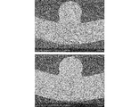
- FIG. Fig. 2-1 shows that the temperature of the wire mesh substrate just before applying the coating solution is heated to approximately 63 ° C by applying the preheating process, and then the catalyst layer is dried and fired.
- FIG. 10 is a view of a SEM photograph of the cross-sectional form at the intersection when forming. The tests were carried out using a coating liquid of the same concentration in which the catalyst component is 100 g / L in all cases and using a nickel-made plain weave wire mesh ( ⁇ 0.15 ⁇ 40 mesh) of the same material and form as the conductive substrate. It is the result of what was done.
- FIG. 2-2 is a SEM photograph of the case where the catalyst layer is formed under the same conditions as in FIG. 2-1 except that the preheating step is not provided.
- the upper and lower data are different on the day of testing.
- the inventor conducted a more detailed examination of the effect obtained by carrying out the above-described preheating step on the conductive substrate (wire net-like substrate) made of a wire mesh just before applying the coating solution.
- the temperature of the wire net-like substrate coated with the coating solution to a certain temperature or more, the drying of the coating solution immediately after the coating is accelerated, and then baking and fixing thereafter wet the coated coating solution.
- the temperature of the wire net-like substrate immediately before applying the coating solution is in the range of 43 ° C. to 120 ° C., whereby in the catalyst layer formed at the intersection of the members.
- the cross-sectional state of the “solidified portion of the liquid pool”, in which the cathode catalyst component is excessively fixed, is surely in the form of a network of fine particles having a large number of soot as shown in FIG. It will have holes. As a result, reduction in the amount of cathode catalyst component to be used can be surely achieved.
- the present inventor carried out determination of the porosity in the cross section of the “solidified portion of liquid pool” by a method described later And the above mentioned temperature range was established. This point will be described in detail in the examples.
- the cathode for electrolysis of the present invention fixes extra catalyst components which may occur at the intersection of the wire net-like substrate. It turned out that the average porosity in the form of the cross section of "solidification part of a liquid pool" becomes 15% or more. Furthermore, it has been found that depending on the conditions, it is possible to eliminate the presence of “solidified portion of the pool” at 100%, that is, at the intersections of the present invention. For this reason, the cathode for electrolysis of the present invention is excellent in economic efficiency in which the coating amount of the expensive cathode catalyst component used for forming the catalyst layer is effectively reduced.
- the average porosity is higher, it means that the amount of the cathode catalyst component such as the coated noble metal is reduced, so to obtain the higher effect of the present invention, It is desirable to determine the conditions of the preheating step such that the average porosity in the form of the cross section of the 'solidified part' is higher. By doing so, the amount of use of the expensive cathode catalyst component used to form the catalyst layer can be further effectively reduced, and the improvement of the economic efficiency of the cathode for electrolysis can be achieved.
- the coating solution containing the cathode catalyst component when the coating solution containing the cathode catalyst component is applied at one or more times, preferably all times when coating is repeated, the coating solution is used. Heating is performed so that the temperature of the conductive cathode substrate immediately before coating is in the range of 43.degree. C. to 120.degree. And, according to this configuration, if the solidified portion of the liquid pool is not or can be recognized at the intersection of the conductive cathode substrate, the form of the cross section of the solidified portion is an average having reticulated pores.
- the nickel component of the conductive cathode substrate does not elute into the cathode catalyst layer, and no nickel precipitates are formed in the cathode catalyst layer. As a result, exfoliation of the cathode catalyst layer caused by the nickel deposit or the nickel layer is prevented.
- the cathode catalyst component used in the present invention contains at least one selected from platinum, iridium, ruthenium, palladium, osmium, nickel or oxides thereof, and also a rare earth element such as lanthanum, cerium, yttrium, titanium, It contains a valve metal such as tantalum or an oxide thereof. While all of these components are expensive rare metal materials, the cathode for electrolysis of the present invention is such that the amount of the cathode catalyst component required for forming the catalyst layer is effectively reduced. For this reason, the cost for the expensive rare metal material is reliably reduced compared to conventional products, and the cathode for electrolysis of the present invention is excellent in economic efficiency.
- the cathode for electrolysis according to the present invention which is excellent in the above-mentioned economy, has a temperature of 43 ° C. to 120 ° C. for the wire mesh substrate just before applying the coating solution in the preheating step performed on the wire mesh substrate at the former stage of the coating process. It can be easily obtained by heating to be in the range of ° C.
- the temperature above 43 ° C. has no remarkable effect, while the temperature above 120 ° C., for example, near the boiling point of the coating liquid, causes the coating liquid to evaporate, which is significantly greater than the boiling point of the coating liquid It is necessary to heat so that it is below the temperature below.
- the critical temperature range defined in the present invention has been experimentally verified. According to the detailed study of the present inventor, the lower limit value at which the remarkable effect of the present invention is obtained is 43 ° C., while the higher the temperature is, the smaller the “solidified portion of liquid pool” which is the subject of the present invention There is a tendency to be possible, and a remarkable effect can be obtained even at 120.degree.
- a high effect is achieved at about 63 ° C. in reducing the cathode catalyst component, and the temperature of the wire mesh substrate just before applying the coating solution is taken into consideration when the cost required for heating is taken into consideration. More preferably, the temperature is about 63.degree.
- the conductive cathode substrate is in a form having a large number of crossings where members cross each other, a coating liquid having an amount more than necessary is applied to the large number of crossings when applied. As a result, a so-called liquid pool is formed. Then, this liquid pool solidifies when it is subjected to a drying / baking step thereafter, and as a result, the cathode catalyst component is excessively fixed to the intersection portion of the conductive base material.
- the solidified part (excessive and wasteful part) containing excess cathode catalyst component resulting from the pooling of the coating solution does not occur at many intersections, Even if a solidified part resulting from the formation of a cross section is generated, the form of the cross section of this part has reticulated pores in which a large number of wrinkles can be confirmed.
- extra and waste solidified parts are reduced, the amount of expensive cathode catalyst component used for the formed cathode catalyst layer can be effectively reduced as compared with the conventional cathode catalyst layer, and as a result, the economy It is possible to provide an electrolytic cathode with excellent characteristics.
- the temperature needs to be 120 ° C. or less. In consideration of the economy, as described above, it is preferable to set the temperature to 63 ° C. or less.
- the inventor raised the temperature of the wire net-like substrate at the time of applying the coating solution at normal temperature (ambient temperature) higher than that at normal temperature (ambient temperature) so as to be within the specific temperature range specified in the present invention.
- This accelerates the drying of the coating liquid immediately after the application to the substrate, accelerates the evaporation of the solvent in the applied coating liquid in the drying step performed after the coating step, and suppresses the wetting and spreading of the coating liquid
- the cross-sectional shape of the “solidified portion of liquid pool” is as shown in FIG. It is considered to be one having a reticulated pore in which a large number of soot can be confirmed, and a mechanism in which the amount of the catalyst component used can be reduced.
- the temperature of the wire net-like substrate at the time of applying the coating liquid at normal temperature is preferably 43 ° C. to 120 ° C.
- the average porosity in the cross-sectional form of “solidified portion of liquid pool” that can occur at many intersections in the metal mesh substrate is , 15% or more.
- the temperature of the wire net-like substrate at the time of applying the coating solution at normal temperature is raised to about 63 ° C.
- the average porosity in the cross-sectional form of the solidified portion of the reservoir can be 44% or more.
- IH Induction heating
- IH is a method of generating current by flowing a current through a heating coil using the principle of electromagnetic induction to cause a metal such as a metal to be heated to generate heat.
- the heating principle is that when an alternating current is supplied to the heating coil, a magnetic flux with a varying strength is generated around the coil.
- Joule heat of (current) 2 ⁇ resistance is generated by the electric resistance of the metal itself, and the metal self-heats. This phenomenon is called induction heating IH.
- IH induction heating
- the coating solution used in the above examples include those comprising a solution obtained by dissolving the starting material of the catalyst component as mentioned above in an inorganic solvent or an organic solvent etc.
- Be prepared an inorganic or organic compound of at least one metal selected from platinum, iridium, ruthenium, palladium, and osmium is used as a starting material of the cathode catalyst component used for producing the insoluble metal anode.
- starting materials include chlorides, sulfates, and nitrates of the above metals.
- dissolved the starting materials mentioned above in the solvent can be used.
- an inorganic or organic compound of a valve metal such as titanium, tantalum, niobium, zirconium, hafnium or the like is further dissolved in an inorganic solvent or an organic solvent to the starting materials of the catalyst components listed above. It is also possible to use inorganic solutions or organic solutions, to which one has been added.
- a nickel compound As a starting material of the cathode catalyst component used for producing the cathode for electrolysis, a nickel compound, a compound of a rare earth element such as lanthanum, cerium, yttrium, a hydrate of oxalic acid, etc. It is preferred to use.
- platinum chloroplatinic acid or platinum nitrate compound: Iridium: iridium chloride ruthenium: ruthenium chloride palladium: palladium chloride titanium: titanium chloride tantalum: tantalum pentachloride cerium: cerium chloride nickel: nickel nitrate
- An acidic solvent can also be used for the coating liquid used in the present invention.
- inorganic acid solvents such as hydrochloric acid, sulfuric acid and nitric acid may be mentioned.
- the solvent of the coating solution used in the present invention may be a mixed solution of the above-mentioned acidic solvent and an organic solvent such as alcohol having high volatility.
- an inorganic solution in which iridium tetrachloride or tantalum pentachloride is dissolved in 35% hydrochloric acid can be mentioned.
- Examples of other coating liquids include mixed inorganic-organic solutions in which ruthenium chloride, iridium chloride and titanium chloride solutions are dissolved in hydrochloric acid and IPA (isopropyl alcohol), and inorganic solutions in which dinitrodiammine platinum and cerium nitrate are dissolved in nitric acid Acidic coating solutions, such as, can also be used.
- the present invention It is not limited to this.
- the number of applications is set to 0.36 g to 0.66 g per application amount.
- the coating amount may be 6 to 12, and the total coating amount may be 2.16 g to 5.28 g.
- What is important in the present invention is that when applying the coating solution at ambient temperature (normal temperature) under such conditions, the temperature of the wire net-like substrate immediately before application is within the range of 43 ° C.
- the temperature is in the range of 43 ° C to 63 ° C.
- the temperature of the wire netting substrate immediately before coating is set to the above temperature all the times each time the coating liquid at ambient temperature (normal temperature) is coated. It is preferable to be in the range.
- the concentration of the cathode catalyst component in the coating solution used in the present invention may be, for example, 20 g / L to 500 g / L although there may be a difference in the coating properties depending on the type of starting material of the catalyst component and the type of solvent.
- the degree is more preferably about 50 g / L to 250 g / L.
- the coated layer formed in the coating step is dried and fired to form a catalyst layer.
- the drying step is not particularly limited, and for example, after being leveled through a drying zone of a continuous furnace following from a coating booth, drying is performed at a set temperature of 30 ° C. to 80 ° C. for a drying time of 5 to 10 minutes.
- This drying step is performed as a pre-baking step after the application of the coating solution, and the metal mesh substrate is heated before the application of the coating solution characterizing the present invention to apply the coating solution. This is clearly distinguished from the preheating step in which the substrate temperature to be provided is within a specific range.
- the coating layer of the coating solution after the drying step 2-3 is fired in the firing step to form a cathode catalyst layer containing a catalyst component (catalyst layer-forming substance).
- a catalyst component catalyst layer-forming substance
- the firing method in the firing step is not particularly limited, and is performed, for example, using a firing zone of a continuous furnace which continues from the drying zone where the drying step is performed.
- the firing conditions are also not particularly limited, and may vary depending on the cathode catalyst component. For example, the firing is conducted under the conditions of a firing time of 10 to 15 minutes and a firing temperature of about 350 to 600.degree.
- the starting material in the coating solution is thermally decomposed, and in the case of an anode, for example, platinum, iridium, ruthenium, palladium, osmium and oxides of these.
- a catalyst layer is formed comprising a cathode catalyst component comprising at least one selected platinum group metal and / or alloy thereof.
- a complex oxide obtained by adding an oxide of a valve metal such as titanium, tantalum, niobium, zirconium, hafnium, etc. to the above-mentioned platinum group metal and / or its oxide.
- a catalyst layer which contains a cathode catalyst component consisting of a solid solution.
- a cathode catalyst layer is formed by containing a mixed oxide of a platinum group metal, nickel and / or an oxide thereof with an oxide of a rare earth element such as cerium or lanthanum.
- post-treatments such as performance adjustment step, neutralization treatment step, shape processing, etc. Is performed to manufacture a cathode for electrolysis.
- post-treatment steps may be performed in the present invention in the same manner as in the conventional method, and are not different from the conventional method.
- the coating process 2-2 is performed again, and then the drying and firing process is repeated to form a cathode catalyst layer having a desired thickness.
- the conductive group after firing is formed.
- the temperature of the material is naturally cooled rapidly because the substrate targeted in the present invention is in the form of a wire net having a large surface area.
- the temperature of the conductive substrate just before applying the coating solution when applying the coating solution again is the ambient temperature. The temperature is lowered to the vicinity, and at least the temperature of 43 ° C. or more specified in the manufacturing method of the present invention does not occur.
- a catalyst layer containing a cathode catalyst component was formed on the metal mesh substrate using a conductive substrate made of a metal mesh by using a coating method.
- the cathode catalyst layer was formed in the procedure of the cathode catalyst layer forming step of At that time, the temperature of the wire net-like substrate immediately before the application of the coating liquid was variously changed by not performing the preheating step 2-1 or by performing the preheating step.
- the other steps 2-2 to 2-4 were performed in the same manner as described later.
- Pretreatment process [1-1: Roughening treatment step] Both surfaces of the wire net-like substrate were subjected to dry blasting with an alumina abrasive (# 320 size) to roughen the surface.
- the electric furnace temperature was set so that the temperature of the wire mesh substrate immediately before applying the coating liquid was the following three types of heating conditions for the wire mesh substrate to be heated.
- the preheating holding time was 5 minutes so that the temperature of the wire mesh substrate uniformly reached the desired temperature.
- immediately before applying the coating liquid at normal temperature (ambient temperature) as described below According to the difference in the temperature of the wire mesh-like base material of the present invention, the examples and the comparative examples were distinguished.
- 63 ° C. means the temperature actually measured with an error of ⁇ 1 ° C. In the entire specification, the notation of 63 ° C. has the same meaning.
- the coating solution is applied to each wire mesh substrate by a combination of the type of the coating solution and the temperature of the wire mesh substrate just before applying the coating solution, and then the drying step and the firing step The coating solution was dried and fired to form a cathode catalyst layer.
- the coating solution was applied promptly using the substrate holding back plate so that the temperature of the wire mesh substrate did not change.
- the "solidified portion of liquid pool" at the intersection of the wire net-like substrate is observed, and the porosity in the cross-sectional form of that portion is measured by the method described later to reduce the cathode catalyst component.
- the degree of The difference in the temperature of the wire mesh substrate immediately before applying the coating solution confirms the difference in the clear form of the "solidified portion of the liquid pool" of the catalyst layer formed, which is the application Because they were caused by the difference in temperature of the wire mesh base immediately before applying the solution, they were designated as Examples 1 to 4 and Comparative Examples 1 and 2 as shown in Table 1.
- Table 1 collectively shows the coating amount of the coating solution and the number of times of coating, together with the temperature of the wire mesh base immediately before the coating solution was applied.
- the substrate temperature in Table 1 is the temperature of the wire mesh substrate immediately before the application of the coating solution, and the application amount is a value calculated from the concentration of the application solution as 100% yield.
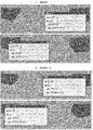
- Examples 3 to 6 For each of the samples of Examples 1 to 4 (Samples 3 to 6) shown in Table 1 and Comparative Examples 1 and 2 (Samples 1 and 2), the “solidified portion of the liquid pool” at the intersection of the wire mesh base 3. To observe the morphology of the step and to measure the porosity, as shown in FIG. Each sample for measurement was prepared in the procedure of sample preparation for porosity measurement. And the porosity in the cross-sectional form of "the solidified part of a liquid pool" was measured by the following method using the prepared sample.
- the porosity was measured using “binarization processing image software” for each of “solidified portion of liquid pool” observed with the extracted electron microscope and extracted.
- An example is shown in FIG. 4 to FIG. Specifically, as shown in FIG. 4, first, with respect to the cross-sectional configuration of “solidified portion of liquid pool” of the extracted image, the range of the solidified portion resulting from liquid pool is specified and recognized. I asked for the area of the part. At the same time, work was carried out to identify and recognize a large number of void portions within the above-specified range, and the area of each void was determined, and the total area of the voids was determined. Then, the ratio of the total area of the pores to the area of the range of the solidified portion due to the liquid pool obtained above was calculated, and this was taken as the porosity in the cross-sectional form of the “solidified portion of the liquid pool”.
- FIG. 4 shows a measurement state of four samples 5 in which the temperature of the wire net-like substrate immediately before applying the low concentration coating solution of 100 g / L in Example 3 was set to 63 ° C.
- the measurement of the porosity as shown in FIG. 4, for each of the four wire net-like substrates, “liquid on both sides of the member in the image of the cross-sectional form of the intersection of the members constituting the wire net” The “solidified portion of the puddle” was measured.
- the number of porosity measurements is eight for each condition.
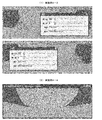
- Example 5 shows a state of measurement of the same porosity as in the above case where the temperature of the wire net-like substrate just before applying the high concentration coating solution of 200 g / L in Example 4 (sample 6) is 63 ° C.
- FIG. 6 shows the “liquid pool of the crossing portion in the case of Comparative Example 1 (Sample 1) in which a low concentration coating solution of 100 g / L was applied to a wire mesh base kept at ambient temperature without preheating.
- the state of measurement of the porosity in the cross-sectional form of the solidified portion is shown.
- the intersection shown in FIG. 6 is clearly different from the cross-sectional configuration of the “solidified portion of the pool” shown in FIG. 4 and FIG. 5, and a large number of soot (such as in the case of the embodiment of the present invention) It did not have the reticulated pore which can be confirmed. For this reason, it was confirmed that the porosity is also clearly smaller than that of the example of the present invention.
- “Solidified solidified portion at the intersection of the wire mesh-like substrates of Comparative Examples 1 and 2 (Samples 1 and 2) and Examples 1 to 4 (Samples 3 to 6) obtained as described above Table 2 and Table 3 collectively show the measurement results of the porosity in the cross-sectional form of ".”
- Table 2 shows the measurement results when a low concentration coating solution of 100 g / L is used
- Table 3 shows the measurement results when a high concentration coating solution of 200 g / L is used.
- FIG. 7 shows the results of measurement of the porosity in the case of using the low concentration coating solution shown in Table 2, obtained as described above with respect to the temperature of the wire net-like substrate just before the application of the coating solution.
- the data of the porosity obtained eight by eight for each of the conditions are plotted.
- the straight lines in FIG. 7 were obtained by statistical processing using these measured values, but showed extremely good correlation.
- a linear function of the following formula (1) was calculated as the approximate expression.
- FIG. 8 shows the results of measurement of porosity in the case of using the high concentration coating solution shown in Table 3 with respect to the temperature of the wire mesh base immediately before applying the coating solution at normal temperature (ambient temperature).
- eight porosity data are plotted for each condition obtained by measurement.
- the straight lines in FIG. 8 were obtained by statistical processing using these measured values, but as in FIG. 7, they showed extremely good correlation.
- a linear function of the following formula (2) was calculated as the approximate expression.
- the method of FIG. 8 using the high concentration coating solution is more stable and reliable when the temperature of the wire mesh substrate immediately before the application of the coating solution is increased. It turned out that the porosity in the cross-sectional form of the "solidification part of a pool" of the intersection part of material can be made high.
- Table 4 shows the measurement results shown in Tables 2 and 3 of each of the examples and comparative examples with the concentration of the coating solution and the temperature of the wire mesh substrate immediately before the application of the coating solution being changed. In each of the conditions, the width (variation) of the measured value of the porosity, the maximum value thereof, and the average porosity are summarized. Table 4 also shows the improvement effect of the porosity obtained by raising the temperature of the wire net-like substrate immediately before the application of the coating liquid, and the tendency of the porosity obtained by increasing the concentration of the coating liquid to improve.
- the porosity in the sample 1 of Comparative Example 1 and the sample 2 of Comparative Example 2 is about 18% at the maximum regardless of the concentration of the coating solution, and the average value is 8%.
- the “solidified portion of the liquid pool” is in a clogged state in which the catalyst component is excessively present, It was confirmed that the cathode catalyst component was wasted in a portion which does not contribute to the improvement of the cathode performance.
- the wire mesh base is heated at a setting temperature of the electric furnace at 60 ° C., and the wire mesh base just before applying the coating solution at normal temperature (ambient temperature)
- the temperature of the material was about 43 ° C. to form a catalyst layer.
- the wire mesh base was heated at a setting temperature of the electric furnace at 90 ° C., and the wire mesh base just before applying the coating solution at normal temperature (ambient temperature) The temperature of the material was set to about 63 ° C. to form a catalyst layer.
- the form of the cross section of “solidified portion of liquid pool” at the crossing portion of the wire mesh base is wrinkled up to the inside It has a mesh-like pore which can be confirmed.
- FIG. 4 shows that the form of the cross section of “solidified portion of liquid pool” at the crossing portion of the wire mesh base is wrinkled up to the inside It has a mesh-like pore which can be confirmed.
- Examples 5 and 6 and Comparative Example 3 Next, in the preheating step performed before the coating step, the temperature of the wire mesh substrate immediately before coating the coating solution was heated to 43 ° C. (Example 5) and 63 ° C. (Example 6) After that, Examples 5 and 6 were obtained by forming a cathode catalyst layer containing a cathode catalyst component on the front side and the back side of the conductive substrate by using a coating method of drying and baking the coating solution applied to the substrate. And the coating method of drying and baking the coating solution applied to the metal mesh substrate at the normal temperature without performing the preheating step, in the same manner as in the above example. An electrolysis test was performed using the cathode for electrolysis of Comparative Example 3 in which the catalyst layer was formed. And about the electrode before and behind electrolysis, the following experiment confirmed about the nickel precipitation part in a cathode catalyst layer, and the state of peeling which arises by it.
- the substrate temperature immediately before the application of the coating solution was measured in advance, and defined as the substrate temperature immediately before the application. Also, by measuring the initial weight of the sample before the evaluation test, it is possible to calculate the exhaustion amount of the catalyst layer generated by the evaluation test.
- Table 6 shows the substrate temperature and the amount of catalyst layer consumed.
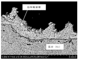
- FIG. 9-1 is a diagram of a SEM photograph of a cross section of the cathode for electrolysis before the electrolysis test of Example 5.
- the nickel of the cathode substrate is not eluted in the cathode catalyst layer, and the cathode catalyst layer is maintained in a stable state composed only of the catalyst component or its oxide.
- electrolysis and reverse electrolysis were performed on the conditions shown in Table 5 using this cathode for electrolysis, peeling of the cathode catalyst layer was not able to be confirmed. This can be confirmed also from the small amount of consumption described above.
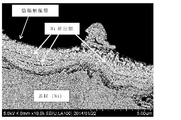
- FIG. 9-2 is a diagram of a SEM photograph of a cross section of the electrode before the electrolysis test of the cathode for electrolysis of Comparative Example 3. It was confirmed that nickel of the cathode substrate was deposited in the cathode catalyst layer to form a layer.
- FIG. 9-3 shows a cross-sectional view of the electrode of Comparative Example 3 after the electrolysis shown in Table 5 and the reverse electrolysis.
- the nickel layer formed by depositing nickel in the cathode substrate in the cathode catalyst layer has been eluted by electrolysis and reverse electrolysis to form voids in the cathode catalyst layer, from which the cathode catalyst layer is peeled off.
- the cathode performance is not impaired.
- the precious metal or the like used for forming the cathode catalyst layer by an extremely simple means of heating the temperature of the wire net-like substrate immediately before applying the coating solution at normal temperature (ambient temperature) to a predetermined temperature. It is possible to reduce the amount of cathode catalyst component used. As a result, an economical cathode for electrolysis can be obtained without impairing the function as a cathode.
- the economical cathode for electrolysis provided by the present invention is useful because the peeling of the cathode catalyst layer caused by long-term electrolysis can be prevented, the consumption amount of the cathode catalyst layer can be reduced, and the durability is improved compared to the conventional electrode. It becomes a thing.
- the cathode for electrolysis of the present invention and the method for producing the same use the amount of the expensive cathode catalyst component used in forming the cathode catalyst layer by a simple method and without reducing the cathode function.
- the effect of reducing the problem of peeling of the catalyst layer is also obtained, and the durability performance can be expected to be improved.
- the cost for raw materials which can be said to be a grave heart in the electrode industry is reduced. It is expected to be widely used because it is a technology to improve the economics.
Landscapes
- Chemical & Material Sciences (AREA)
- Engineering & Computer Science (AREA)
- Materials Engineering (AREA)
- Organic Chemistry (AREA)
- Chemical Kinetics & Catalysis (AREA)
- Electrochemistry (AREA)
- Metallurgy (AREA)
- Electrodes For Compound Or Non-Metal Manufacture (AREA)
- Fuel Cell (AREA)
- Catalysts (AREA)
Priority Applications (5)
| Application Number | Priority Date | Filing Date | Title |
|---|---|---|---|
| CN201580038450.2A CN106661745B (zh) | 2014-07-15 | 2015-07-14 | 电解用阴极和电解用阴极的制造方法 |
| EP15822165.5A EP3187626B1 (de) | 2014-07-15 | 2015-07-14 | Elektrolysekathode und verfahren zur herstellung einer elektrolysekathode |
| KR1020177000542A KR101894427B1 (ko) | 2014-07-15 | 2015-07-14 | 전해용 음극 및 전해용 음극의 제조 방법 |
| JP2016534453A JP6374966B2 (ja) | 2014-07-15 | 2015-07-14 | 電解用陰極及び電解用陰極の製造方法 |
| US15/316,733 US10676831B2 (en) | 2014-07-15 | 2015-07-14 | Electrolysis cathode and method for producing electrolysis cathode |
Applications Claiming Priority (2)
| Application Number | Priority Date | Filing Date | Title |
|---|---|---|---|
| JP2014145423 | 2014-07-15 | ||
| JP2014-145423 | 2014-07-15 |
Publications (1)
| Publication Number | Publication Date |
|---|---|
| WO2016010045A1 true WO2016010045A1 (ja) | 2016-01-21 |
Family
ID=55078535
Family Applications (1)
| Application Number | Title | Priority Date | Filing Date |
|---|---|---|---|
| PCT/JP2015/070185 WO2016010045A1 (ja) | 2014-07-15 | 2015-07-14 | 電解用陰極及び電解用陰極の製造方法 |
Country Status (7)
| Country | Link |
|---|---|
| US (1) | US10676831B2 (de) |
| EP (1) | EP3187626B1 (de) |
| JP (1) | JP6374966B2 (de) |
| KR (1) | KR101894427B1 (de) |
| CN (1) | CN106661745B (de) |
| TW (1) | TWI650446B (de) |
| WO (1) | WO2016010045A1 (de) |
Cited By (2)
| Publication number | Priority date | Publication date | Assignee | Title |
|---|---|---|---|---|
| JPWO2018151228A1 (ja) * | 2017-02-15 | 2019-02-21 | 旭化成株式会社 | 陰極、その製造方法、およびそれを用いた電解槽、水素製造方法 |
| WO2024262444A1 (ja) * | 2023-06-23 | 2024-12-26 | パナソニックIpマネジメント株式会社 | 水電解用電極の製造方法 |
Families Citing this family (4)
| Publication number | Priority date | Publication date | Assignee | Title |
|---|---|---|---|---|
| US10466515B2 (en) | 2016-03-15 | 2019-11-05 | Intel Corporation | On-chip optical isolator |
| US20180059446A1 (en) * | 2016-08-29 | 2018-03-01 | Woosung Kim | Optical iso-modulator |
| JP6500937B2 (ja) * | 2017-05-29 | 2019-04-17 | 住友金属鉱山株式会社 | 金属電着用陰極板及びその製造方法 |
| WO2023150511A2 (en) * | 2022-02-01 | 2023-08-10 | Verdagy, Inc. | Flattened wire mesh electrode in an electrolyzer |
Citations (3)
| Publication number | Priority date | Publication date | Assignee | Title |
|---|---|---|---|---|
| JPS5522556B2 (de) * | 1975-05-12 | 1980-06-17 | ||
| JPH03253590A (ja) * | 1990-03-02 | 1991-11-12 | Permelec Electrode Ltd | 水電解用電極の製造方法 |
| JP5548296B1 (ja) * | 2013-09-06 | 2014-07-16 | ペルメレック電極株式会社 | 電解用電極の製造方法 |
Family Cites Families (9)
| Publication number | Priority date | Publication date | Assignee | Title |
|---|---|---|---|---|
| BE793979A (fr) | 1972-01-15 | 1973-07-12 | Kalle Ag | Procede pour produire des cliches pour l'impression a plat et matiere pour de tels cliches |
| US4300992A (en) * | 1975-05-12 | 1981-11-17 | Hodogaya Chemical Co., Ltd. | Activated cathode |
| US5164062A (en) * | 1990-05-29 | 1992-11-17 | The Dow Chemical Company | Electrocatalytic cathodes and method of preparation |
| JP3253590B2 (ja) | 1998-08-31 | 2002-02-04 | シャープ株式会社 | ハーフトーンマスクの製造方法 |
| JP4142191B2 (ja) * | 1999-02-24 | 2008-08-27 | ペルメレック電極株式会社 | 活性化陰極の製造方法 |
| JP2004196646A (ja) * | 2002-10-23 | 2004-07-15 | Nissan Motor Co Ltd | 燃料改質装置 |
| TW200304503A (en) * | 2002-03-20 | 2003-10-01 | Asahi Chemical Ind | Electrode for generation of hydrogen |
| TWI255865B (en) | 2002-11-27 | 2006-06-01 | Asahi Kasei Chemicals Corp | Bipolar, zero-gap type electrolytic cell |
| JP5522556B1 (ja) | 2013-06-05 | 2014-06-18 | 山佐株式会社 | 遊技機 |
-
2015
- 2015-07-14 EP EP15822165.5A patent/EP3187626B1/de active Active
- 2015-07-14 JP JP2016534453A patent/JP6374966B2/ja active Active
- 2015-07-14 WO PCT/JP2015/070185 patent/WO2016010045A1/ja active Application Filing
- 2015-07-14 US US15/316,733 patent/US10676831B2/en active Active
- 2015-07-14 KR KR1020177000542A patent/KR101894427B1/ko active IP Right Grant
- 2015-07-14 CN CN201580038450.2A patent/CN106661745B/zh active Active
- 2015-07-15 TW TW104122921A patent/TWI650446B/zh active
Patent Citations (3)
| Publication number | Priority date | Publication date | Assignee | Title |
|---|---|---|---|---|
| JPS5522556B2 (de) * | 1975-05-12 | 1980-06-17 | ||
| JPH03253590A (ja) * | 1990-03-02 | 1991-11-12 | Permelec Electrode Ltd | 水電解用電極の製造方法 |
| JP5548296B1 (ja) * | 2013-09-06 | 2014-07-16 | ペルメレック電極株式会社 | 電解用電極の製造方法 |
Cited By (4)
| Publication number | Priority date | Publication date | Assignee | Title |
|---|---|---|---|---|
| JPWO2018151228A1 (ja) * | 2017-02-15 | 2019-02-21 | 旭化成株式会社 | 陰極、その製造方法、およびそれを用いた電解槽、水素製造方法 |
| JP2019073806A (ja) * | 2017-02-15 | 2019-05-16 | 旭化成株式会社 | 陰極、その製造方法、およびそれを用いた電解槽、水素製造方法 |
| JP7323299B2 (ja) | 2017-02-15 | 2023-08-08 | 旭化成株式会社 | 陰極、その製造方法、およびそれを用いた電解槽、水素製造方法 |
| WO2024262444A1 (ja) * | 2023-06-23 | 2024-12-26 | パナソニックIpマネジメント株式会社 | 水電解用電極の製造方法 |
Also Published As
| Publication number | Publication date |
|---|---|
| JPWO2016010045A1 (ja) | 2017-04-27 |
| CN106661745B (zh) | 2020-05-01 |
| KR101894427B1 (ko) | 2018-09-04 |
| KR20170018893A (ko) | 2017-02-20 |
| EP3187626A1 (de) | 2017-07-05 |
| EP3187626B1 (de) | 2020-09-16 |
| TWI650446B (zh) | 2019-02-11 |
| JP6374966B2 (ja) | 2018-08-15 |
| CN106661745A (zh) | 2017-05-10 |
| US20170198402A1 (en) | 2017-07-13 |
| TW201612360A (en) | 2016-04-01 |
| US10676831B2 (en) | 2020-06-09 |
| EP3187626A4 (de) | 2018-05-16 |
Similar Documents
| Publication | Publication Date | Title |
|---|---|---|
| WO2016010045A1 (ja) | 電解用陰極及び電解用陰極の製造方法 | |
| JP5548296B1 (ja) | 電解用電極の製造方法 | |
| JP6670750B2 (ja) | 処理チャンバ用のチャンバコンポーネント及びその製造方法 | |
| CN101235513B (zh) | 一种新型涂层钛阳极 | |
| JP2008004498A (ja) | 酸化性環境下に長期間さらされても接触抵抗が増加することの少ない複合層被覆金属板 | |
| JP2007332437A (ja) | 微細構造体の製造方法および微細構造体 | |
| JP2023523690A (ja) | 電極を製造するための金属基材の処理のための方法 | |
| JP2007231339A (ja) | 微細構造体の製造方法および微細構造体 | |
| TWI606147B (zh) | Cathode for electrolysis, method for producing the same, and electrolytic cell for electrolysis | |
| JP4884202B2 (ja) | 微細構造体の製造方法および微細構造体 | |
| KR101681537B1 (ko) | 불용성 전극의 제조방법 및 이에 의해 제조된 불용성 전극 | |
| Li et al. | A modified quantitative method for regularity evaluation of porous AAO and related intrinsic mechanisms | |
| JP5789058B2 (ja) | 光触媒体の製造方法 | |
| TWI472424B (zh) | A metal material, a surface treatment method of a metal material, a method of manufacturing a water repellent material using a metal material as a substrate, and a manufacturing apparatus for a metal material | |
| Jin et al. | Controllable fabrication and microstructure modulation of unique AAO structures based on patterned aluminum surface | |
| JPS5964788A (ja) | 電解用電極およびその製造方法 | |
| JP6200882B2 (ja) | 水素水生成用電極及び製造方法 | |
| JP5966782B2 (ja) | 不溶性陽極 | |
| TW574414B (en) | Process for producing Al2O3 ceramic coating on MAR-M247 superalloy by electrolytic deposition | |
| JP2024540996A (ja) | 次亜塩素酸塩発生用電極 | |
| JP2022124171A (ja) | 金属コロイド水生成装置及び金属コロイド水生成方法 | |
| Hasegawa et al. | Alumina Coating on Stainless Steel Wire Net by Electrophoretic Deposition and its Oxidation Resistance | |
| JP2010168617A (ja) | 微細構造体の製造方法 |
Legal Events
| Date | Code | Title | Description |
|---|---|---|---|
| 121 | Ep: the epo has been informed by wipo that ep was designated in this application |
Ref document number: 15822165 Country of ref document: EP Kind code of ref document: A1 |
|
| ENP | Entry into the national phase |
Ref document number: 2016534453 Country of ref document: JP Kind code of ref document: A |
|
| REEP | Request for entry into the european phase |
Ref document number: 2015822165 Country of ref document: EP |
|
| WWE | Wipo information: entry into national phase |
Ref document number: 15316733 Country of ref document: US |
|
| ENP | Entry into the national phase |
Ref document number: 20177000542 Country of ref document: KR Kind code of ref document: A |
|
| NENP | Non-entry into the national phase |
Ref country code: DE |