WO2016006768A1 - 수화열 에너지 저장용 축열재 및 이의 제조방법 - Google Patents
수화열 에너지 저장용 축열재 및 이의 제조방법 Download PDFInfo
- Publication number
- WO2016006768A1 WO2016006768A1 PCT/KR2014/010639 KR2014010639W WO2016006768A1 WO 2016006768 A1 WO2016006768 A1 WO 2016006768A1 KR 2014010639 W KR2014010639 W KR 2014010639W WO 2016006768 A1 WO2016006768 A1 WO 2016006768A1
- Authority
- WO
- WIPO (PCT)
- Prior art keywords
- heat
- storage material
- heat storage
- salt
- hydration
- Prior art date
- Legal status (The legal status is an assumption and is not a legal conclusion. Google has not performed a legal analysis and makes no representation as to the accuracy of the status listed.)
- Ceased
Links
Images


Classifications
-
- C—CHEMISTRY; METALLURGY
- C09—DYES; PAINTS; POLISHES; NATURAL RESINS; ADHESIVES; COMPOSITIONS NOT OTHERWISE PROVIDED FOR; APPLICATIONS OF MATERIALS NOT OTHERWISE PROVIDED FOR
- C09K—MATERIALS FOR MISCELLANEOUS APPLICATIONS, NOT PROVIDED FOR ELSEWHERE
- C09K5/00—Heat-transfer, heat-exchange or heat-storage materials, e.g. refrigerants; Materials for the production of heat or cold by chemical reactions other than by combustion
- C09K5/16—Materials undergoing chemical reactions when used
-
- Y—GENERAL TAGGING OF NEW TECHNOLOGICAL DEVELOPMENTS; GENERAL TAGGING OF CROSS-SECTIONAL TECHNOLOGIES SPANNING OVER SEVERAL SECTIONS OF THE IPC; TECHNICAL SUBJECTS COVERED BY FORMER USPC CROSS-REFERENCE ART COLLECTIONS [XRACs] AND DIGESTS
- Y02—TECHNOLOGIES OR APPLICATIONS FOR MITIGATION OR ADAPTATION AGAINST CLIMATE CHANGE
- Y02P—CLIMATE CHANGE MITIGATION TECHNOLOGIES IN THE PRODUCTION OR PROCESSING OF GOODS
- Y02P20/00—Technologies relating to chemical industry
- Y02P20/10—Process efficiency
Definitions
- the present invention relates to a method of using the heat of hydration energy, and relates to a heat storage material and a method for producing the same, the reaction heat is stored semi-permanently by impregnating a salt in the porous carrier, is semi-permanently regenerated.
- the calorific value is very large and generates heat of 400 ° C. or higher, which makes it unsuitable for heating, and in order to use such high temperature, water or other heat conductors are used as heat transfer mediums.
- the efficiency is low, there is a disadvantage that additional devices, etc. are required.
- these salts have the property of absorbing moisture in the air, so in order to store heat for a long time and use it at the proper time, it must be stored in a closed space that is blocked from the outside to proceed with dehydration and hydration.
- the salt covering the heat transfer interface during the dehydration is accompanied by a local overheating phenomenon, resulting in a problem that the salt is pyrolyzed due to excessively high temperature.
- the dehydration temperature is higher than 120 °C decomposes and discharges hydrogen chloride gas, in addition to the problem that the salt is gradually lost, the problem of corrosion by hydrogen chloride gas is raised.
- An object of the present invention is to regenerate the salt by impregnating the salt in the porous carrier in the use of heat of hydration energy, to remove the salt agglomeration phenomenon, to prevent thermal decomposition problems of the salt due to local overheating phenomenon and to increase the interface of the material transfer and heat transfer and its To provide a manufacturing method.
- the heat storage material according to an embodiment of the present invention is a porous carrier; And a salt impregnated in the porous carrier, wherein the heat of hydration energy is stored.
- the porous carrier may be any one selected from the group consisting of pearlite, zeolite, activated carbon, and a combination thereof.
- the porous carrier may have a specific surface area of 0.001 to 10.0 m 2 / g.
- the salt may be any one selected from the group consisting of metal chloride salts, metal sulfate salts, metal nitrate salts, and combinations thereof.
- the heat storage material may generate a heat of hydration by humidification, thereby lowering the stored heat of hydration energy.
- Lower hydration heat energy of the heat storage material can be recovered by heating dehydration.
- the heat dehydration reaction may be performed by any one heat selected from the group consisting of solar heat, waste heat, and a combination thereof.
- the heat storage material may have an average apparent diameter of 0.5 mm to 50 mm.
- the heat storage material may be a calorific value of 700 to 1700 MJ / m 3 per unit volume due to humidification.
- the heat storage material may be any one type selected from the group consisting of blocks, honeycombs, and combinations thereof.
- Method for producing a heat storage material preparing a salt solution by mixing a salt and a solvent; Supporting the porous carrier in the salt solution, so that the salt is impregnated into the porous carrier; And drying the salt-impregnated porous carrier, wherein the heat storage material stores hydration heat energy.
- the solvent may have a boiling point of 130 ° C. or less.
- the concentration of the salt solution may be 50% to 80%.
- the drying may be dried by any one selected from the group consisting of heat drying, hot air drying, natural drying, vacuum drying and combinations thereof.
- the drying may be performed at a temperature condition of 50 to 250 °C.
- the heat storage material according to an embodiment of the present invention, a porous carrier and a salt impregnated in the porous carrier, the heat storage material is that the heat of hydration energy is stored.
- the salt may be any one selected from the group consisting of metal chloride salts, metal sulfate salts, metal nitrate salts, and combinations thereof.
- metal chloride salts metal sulfate salts, metal nitrate salts, and combinations thereof.
- magnesium chloride, calcium chloride, zinc chloride, aluminum chloride, and the like may be applied to the metal chloride, and the metal sulfate may be applied to magnesium sulfate, calcium sulfate, zinc sulfate, aluminum sulfate, and the like.
- Aluminum, calcium nitrate, magnesium nitrate, zinc nitrate and the like can be applied.
- the salt may preferably be magnesium chloride or calcium chloride, and the application of magnesium chloride or calcium chloride as the salt may increase the calorific value of the heat storage material, but is not limited thereto. Zeolite or silica gel may also be applied as the salt.
- the porous carrier may be applied without limitation as long as the pores are sufficient to increase the reaction interface, and for example, pearlite, zeolite, activated carbon, or a mixture thereof may be applied.
- the porous carrier may have a specific surface area of 0.001 to 10.0 m 2 / g, preferably 0.5 to 10.0 m 2 / g, and when the specific surface area is less than 0.001 m 2 / g, the reaction interface may not be sufficient to transfer materials and heat. This may not be smooth, and when the specific surface area exceeds 10.0 m 2 / g, when applied to the reactor or the like, the path formation of the wet air may not be made smoothly, the strength of the heat storage material can be reduced.
- Hydration heat energy stored in the heat storage material may be understood as an ability to generate heat of hydration, that is, a heat generation potential, and the heat generation potential has a maximum value when the heat storage material is dry.
- the impregnated salt may have a minimum when it is hydrated as much as possible by humidification, for example when it becomes hexahydrate in the case of magnesium chloride.
- the heat storage material may participate as a reactant to generate heat of hydration, thereby lowering the heat of hydration energy stored in the heat storage material.
- the heat amount that can be generated by the heat storage material that is, the calorific value may be 700 to 1700 MJ / m 3 per unit volume of the heat storage material, but the heat amount that the heat storage material can generate is not limited to this range.
- the amount of heat that can be generated may vary depending on the application or size.
- This may be a low value compared to general fossil fuels, but the heat storage material has no discharge of harmful substances such as fossil fuels, may be recycled semi-permanently rather than once, and may be manufactured in a simple manner.
- the heating dehydration performed at this time may be performed by solar heat, waste heat or a combination thereof.
- Hydration heat energy can be used to recover hydration heat energy with strong solar heat in summer, and can be used in winter, and hydration heat energy as waste heat such as hot air or steam generated after heat exchange in plant such as manufacturing plant or power plant Can recover. Since the surplus energy is also used to recover the hydration heat energy of the heat storage material, the heat storage material may be more environmentally friendly than fossil fuels.
- the heat storage material may have an average apparent diameter of 0.5 mm to 50 mm, preferably 0.5 to 20 mm.
- the average apparent diameter of the heat storage material exceeds 50 mm, when applied to a heating device or a reactor, it may not be possible to secure a sufficient reaction interface in the space where the hydration reaction occurs, thereby reducing the amount of heat of hydration and efficiency.
- the average apparent diameter is less than 0.5 mm, when applied to a heating device or a reactor, the air permeability may not be secured so that the passage path of water may not be smoothly formed.
- the shape of the heat storage material particles is irregular, each particle may have a different shape, and may not be a standard form such as spherical or hexahedral. Since the heat storage material particles have an irregular shape, when applied to a heating device or a reactor, the contact area with moisture such as wet air, that is, the reaction interface can be greatly increased.
- the heating device to which the heat storage material may be applied may be, for example, an air heater, and the air heater may include a reaction part including a heating material in contact with moisture to cause a hydration reaction to be blocked from the outside; And a supply part connected to the reaction part and supplying a fluid containing water to the reaction part, wherein the heat storage material may be applied as a heating material of a heater.
- the reaction part of the heater includes two or more sub-reaction parts separated from each other and blocked from the outside, and each of the sub-reaction parts includes a heating material, and the supply part is connected to the sub-reaction parts to connect the respective sub-reaction parts. It may include a sub-supply unit for supplying a fluid to.
- reaction part in the heater includes two or more sub-reaction parts
- a plurality of reaction parts for generating a hydration reaction by the exothermic material may increase the temperature of a predetermined space or maintain the heating for a long time.
- the material forming the outer surface of the reaction part, or the material forming the partition or outer surface of the sub-reaction parts may be a flexible material.
- Material such as the reaction unit can be selectively applied according to the use of the heater, it may be preferable to use a flexible material in the case of the thermal mat and hot pack, and when used as a heater to heat the air to heat the space It may be desirable to use a rigid material in terms of storage, movement, care and the like.
- the heater may further include a discharge part connected to the reaction part, and the discharge part may be a discharge of the warm air warmed by the heating heat inside the reaction part.
- the outlet of the heater may be selectively included or not included depending on the use of the heater.
- the reaction part when used for applications such as hot packs or thermal mats, the reaction part may be manufactured to an appropriate size in consideration of volume expansion, and the discharge part may be removed to fill the inner empty space with hot air to heat the air by heating the space.
- the discharge part When used as a heater may be used to include a discharge so that the heated air can be immediately discharged to the outside.
- the discharge unit may also include a sub-discharge unit corresponding to each.
- the heat storage material may also be applied to a heating method using air, wherein the heating method uses the above-described heater, and the fluid containing moisture introduced into the reaction part contacts the heating element to cause a hydration reaction, and the hydration It may include a heating step of heating the air in the reaction unit using the heating heat containing the heat of hydration generated in the process of changing the heat generating material into a hydrate by the reaction, and transfers heat to the outside of the heater using the heated air. .
- the heat storage material according to an embodiment of the present invention may be applied as the heating material, and the fluid flowing into the reaction part may further use sprayed water or condensation heat in the form of droplets to increase reaction speed and induce a uniform reaction. It may be air containing water vapor to.
- the amount of water vapor included in the air may be 60% by weight relative to the total air, that is, relative humidity is about 60% or more, and 70% or more may be more preferable in order to further maximize heating efficiency by providing water as a source of moisture. have.
- the heating method using the air may further include a wet air generation step before the heating step or at the same time as the heating step.
- the wet air generation step may be a step of evaporating water to water vapor and transferring the water vapor to the reaction unit through the supply unit.
- Various methods may be used as the method of evaporating water with steam in the wet air generation step, for example, there may be a vacuum evaporation method, an evaporation method by heating, and the vacuum evaporation method may be appropriate in the present invention. have. That is, the water is evaporated to water vapor through a pressure drop using a vacuum pump, and the generated water vapor may be delivered to the reaction part through the supply part to which the fluid connected to the vacuum pump is supplied.
- the heating method using the air may further include a drying step and a storage step after the heating step.
- the drying step may be a step of drying the hydrate of the heating material to regenerate the heating material.
- the heating method using the air after such a storage step, returns to the heating step again to cause a hydration reaction of the heating material, and to transfer heat to the outside of the heater through the discharge unit or with the air warmed in the reaction unit. It may be reused in the manner used for heating.
- the heating method can be applied semi-permanently through the circulation method of heating, drying and storage, energy can be greatly reduced, and environmental pollution problems and resource shortages using only heating materials and water without using fossil fuels. It can be said to be a heating method that can actively cope with problems.
- the heat storage material is not limited to being applied to the air heater or the heating method using air, but by applying the heat storage material of the present invention, the efficiency of the heater or heating method can be further maximized, and salt is used as a heat generating material. It can be more useful because it can solve all the problems that occur when.
- Method for producing a heat storage material comprises the steps of preparing a salt solution by mixing a salt and a solvent; Supporting the porous carrier in the salt solution, so that the salt is impregnated into the porous carrier; And drying the salt-impregnated porous carrier.
- the heat storage material may be one in which hydration heat energy is stored.
- the solvent may have a boiling point of 130 ° C. or less.
- any solvent that can be evaporated at 130 ° C. or lower is applicable.
- water such as distilled water or deionized water, alcohol such as methanol or ethanol, etc. This can be applied.
- the concentration of the salt solution may be 50% to 80% saturated aqueous solution.
- the concentration range may be the concentration of the salt for the salt is sufficiently impregnated in the supported porous carrier.
- Low concentrations of the salt solution can reduce the amount of salts impregnated in the same amount of porous carrier, thereby reducing the calorific value, and the amount of heat required to evaporate the water contained in the salt solution increases the overall energy efficiency. Can be degraded.
- the drying may be dried by, for example, heat drying, hot air drying, natural drying, vacuum drying, or a combination thereof. As long as it is possible to vaporize the solvent to make the heat storage material anhydrous, it can be applied without particular limitation.
- the drying may be carried out at a temperature condition of 50 to 250 °C, preferably 50 to 150 °C. If the drying temperature is lower than 50 °C, the time required for drying may be considerable, may be inefficient, the heat storage material may not be uniformly dried, if the drying temperature is higher than 250 °C, the salt may be pyrolyzed and energy consumption Too much can be uneconomical. That is, in terms of improving energy use efficiency, it may be desirable to dry at the lowest possible temperature if it can be sufficiently heated.
- the heat storage material of the present invention can prevent the salt agglomeration that can occur during the hydration reaction to prevent thermal decomposition and loss of the salt due to local overheating, the reaction interface is increased due to the salt is impregnated into the porous carrier material transfer and heat transfer
- the efficiency can be increased, and can be prepared by a simple method such as being supported in a salt solution, and can be used by semi-permanently regenerating has the advantage of being environmentally friendly.
- the efficiency can be increased, it can solve the existing problem.
- FIG. 1 is a schematic view showing a method of manufacturing a heat storage material according to an embodiment of the present invention.
- Figure 2 schematically shows a heat storage material according to an embodiment of the present invention.
- Figure 3 is a schematic diagram showing the movement path of the wet air in the salt powder and the heat storage material according to an embodiment of the present invention.
- Figure 4 is a schematic diagram showing a case where the salt powder and the heat storage material according to an embodiment of the present invention is filled in the reactor.
- FIG 5 is a graph showing a change in temperature over time of the hydration reaction of the salt powder (TC2) and the heat storage material (TC1) according to an embodiment of the present invention.
- calcium chloride anhydride (CaCl 2 Anhydrous) was prepared as distilled water and salt powder as a solvent. 200 g of the distilled water and 600 g of the calcium chloride anhydride were mixed to prepare an aqueous salt solution having a concentration of 75% as shown in the second state of FIG. 1.
- perlite was prepared as a porous carrier, and it was supported in the aqueous salt solution as in the third state of FIG. 1. Thereafter, the salt aqueous solution was heated to about 100 ° C. to evaporate all of the water, and the salt impregnated in pearlite was made anhydrous using a hot air of about 120 ° C. to prepare a heat storage material as in the fourth state of FIG. 1. .
- the heat storage material prepared in Preparation Example was introduced into the reactor.
- a temperature of about 30 ° C. and air containing about 70% of water vapor were added thereto to induce hydration of the heat storage material.
- the water provided for the hydration was about 70 g.
- the temperature of the air in the reactor rises from the time point at which the wet air is provided in the reactor and the temperature is maintained, and the results are shown in Table 1 and FIG. 5.
- the hydration reaction was induced in the same manner as in the above example except that 600 g of CaCl 2 anhydride was added to the reactor as a heating material.
- the temperature of the air in the reactor rises from the time point at which the wet air is provided in the reactor and the temperature is maintained, and the results are shown in Table 1 and FIG. 5.
- the heat storage material when used, the time taken to reach the maximum temperature is shorter, and the maximum temperature increase is also larger. As shown in FIG. 4, the heat storage material has better air permeability than the general salt particles. It can be confirmed that it is because of the size.
Landscapes
- Chemical & Material Sciences (AREA)
- Engineering & Computer Science (AREA)
- Physics & Mathematics (AREA)
- Chemical Kinetics & Catalysis (AREA)
- Combustion & Propulsion (AREA)
- Thermal Sciences (AREA)
- Materials Engineering (AREA)
- Organic Chemistry (AREA)
- Sorption Type Refrigeration Machines (AREA)
Abstract
본 발명의 축열재는 다공성 담체 및 상기 다공성 담체에 함침된 염을 포함하고, 상기 축열재는 수화열 에너지가 저장된 것이며, 이의 제조방법은 염과 용매를 혼합하여 염 용액을 제조하는 단계; 상기 염 용액에 다공성 담체를 담지하여, 상기 다공성 담체에 염이 함침되는 단계; 및 상기 염이 함침된 다공성 담체가 건조되는 단계;를 포함한다. 제조된 축열재는 물질전달 및 열전달 효율이 높고, 반영구적으로 사용이 가능하여 친환경적일 수 있다.
Description
본 발명은 수화열 에너지를 이용하는 방법에 관한 것으로, 다공성 담체에 염을 함침시킴으로써 수화열 에너지를 저장하여, 반영구적으로 재생되며, 반응 계면이 큰 축열재 및 이의 제조방법에 관한 것이다.
실내 난방을 위해서는 난방용 배관설비와 방열기를 갖추고 공급되는 온수의 열량을 이용하거나 석탄, 석유, 가스 등의 화석연료의 연소열을 이용하거나 전열기구 등으로 전기를 이용하는 것이 대부분이다. 최근 유가가 지속적으로 폭등하고 있고, 앞으로도 유가 하락이 전망되지 않을 뿐만 아니라, 한정된 자원을 이용하는 것으로, 이미 상당한 관심을 끌고 있는 환경문제와도 직결되는 부분이라 할 수 있다. 이와 관련하여 대체연료를 이용하는 기기 또는 고효율의 난방기기를 개발하는 것이 필요하다.
또한, 현재 소형의 보조 난방방식으로는 손난로, 핫팩 등이 사용되고 있지만 소용량이며 한번 사용 후 재생이 불가능한 제품이다(철 분말, 활성탄, 염화나트륨 등의 혼합물을 사용한 제품). 일회용으로 쓰이고 폐기될 경우, 그 폐기물 처리도 문제가 되고, 비용적인 손실도 크며, 핫팩의 경우 재생이 가능한 방식이지만 액체상태로 되어있어 취급이 불편하고 저장, 이동시에 충격 등으로 인하여 반응이 원치 않는 시간에 일어나는 단점이 있다. 그리고 내용물의 응고열만을 이용하여 발열량이 작아 효율이 상당히 낮다는 단점이 있다.
나아가, 특정 화학반응을 이용하여 발열 시키는 경우에도, 발열량이 매우 커 400℃ 이상의 열을 발생시켜 난방으로의 이용이 부적합하고, 이러한 고온을 이용하기 위해 열전달 매체인 물이나 기타 열전도체를 사용하여 열 효율이 낮으며, 추가적인 장치 등이 필요하다는 단점이 있다.
이러한 단점을 해결하기 위해, 수화물을 형성하는 염을 사용하여 수화반응으로부터 발생하는 수화열을 이용하는 방법이 있다. 일 예로 염화마그네슘과 같이 수화물을 형성하는 염들은 무수상태에서 수화물을 형성하는 과정에서 수화열을 발생시킨다. 이러한 염의 특성을 이용하면, 태양열이나 공장 등지에서 발생하는 폐열 등으로 염이 함유하고 있는 수분을 제거하고 밀봉하여 저장한 후, 추후 필요한 시간과 필요한 장소에서 수분을 첨가하면 열을 얻을 수 있다. 특히 태양열 이용의 경우, 하절기의 태양열을 비축하여 동절기에 사용할 수 있는 등 에너지 이용에 많은 가능성을 제공할 수 있다.
그러나, 이러한 염들을 사용하는 데에는 여러 가지 제약사항이 있다. 우선 이 염들은 공기 중의 수분을 흡수하는 특성이 있어 장기간 동안 열을 비축한 후 적정시점에 사용하려면 외부와 차단된 밀폐공간에 저장되어 탈수와 수화가 진행되어야 한다.
또한, 이러한 염들은 탈수 및 수화과정에서 서로 결합하여 큰 덩어리로 뭉침으로써 열전달 및 물질전달이 매우 불리하여 탈수와 수화 즉, 열을 저장하고 저장된 열을 이용하는 데에 큰 장애요인이 된다.
또한, 탈수과정에서 열전달 계면을 덮고 있는 염으로 인해 국부적 과열현상이 동반되며 이로 인해 온도가 과다하게 높아지면서 염이 열분해되는 문제가 발생한다. 일 예로 염화마그네슘의 경우 탈수 온도가 120℃를 상회하면 분해되어 염화수소가스를 배출함으로써, 염이 점차적으로 소실되는 문제 이외에 염화수소가스에 의한 부식문제가 대두된다.
이에, 이러한 염을 열저장 매체로 사용하려면 물질(예, 수분) 및 열이 큰 저항 없이 이동할 수 있도록 계면이 충분히 큰 상태가 되어야 할 필요가 있다.
본 발명의 목적은 수화열 에너지를 이용함에 있어서 염을 다공성 담체에 함침시킴으로써, 염의 뭉침 현상을 제거하여, 국부적 과열현상으로 인한 염의 열분해 문제를 방지하고 물질전달 및 열전달의 계면을 증대시킨 축열재 및 이의 제조방법을 제공하기 위함이다.
본 발명의 일 실시예에 따른 축열재는 다공성 담체; 및 상기 다공성 담체에 함침된 염;을 포함하고, 수화열 에너지가 저장된 것이다.
상기 다공성 담체는 펄라이트(pearlite), 제올라이트 (zeolite), 활성탄 및 이들의 조합으로 이루어진 군에서 선택된 어느 하나일 수 있다.
상기 다공성 담체는 비표면적이 0.001 내지 10.0 m2/g인 것일 수 있다.
상기 염은 염화금속염, 황산금속염, 질산금속염 및 이들의 조합으로 이루어진 군에서 선택된 어느 하나일 수 있다.
상기 축열재는 가습에 의해 수화열이 발생되어 저장된 수화열 에너지가 낮아질 수 있다.
상기 축열재의 낮아진 수화열 에너지는 가열 탈수에 의해 회복될 수 있다.
상기 가열 탈수반응은 태양열, 폐열 및 이들의 조합으로 이루어진 군에서 선택된 어느 하나의 열에 의해 수행될 수 있다.
상기 축열재는 평균 겉보기 직경이 0.5 mm 내지 50 mm 일 수 있다.
상기 축열재는 가습에 의한 단위 부피당 발열량이 700 내지 1700 MJ/m3인 것일 수 있다.
상기 축열재는 블록, 벌집 및 이들의 조합으로 이루어진 군에서 선택된 어느 하나의 형태일 수 있다.
본 발명의 다른 일 실시예에 따른 축열재의 제조방법은, 염과 용매를 혼합하여 염 용액을 제조하는 단계; 상기 염 용액에 다공성 담체를 담지하여, 상기 다공성 담체에 염이 함침되는 단계; 및 상기 염이 함침된 다공성 담체가 건조되는 단계;를 포함하고, 상기 축열재에는 수화열 에너지가 저장된다.
상기 용매는 끓는점이 130℃ 이하일 수 있다.
상기 염 용액의 농도는 50% 내지 80%일 수 있다.
상기 건조는 가열 건조, 열풍 건조, 자연 건조, 진공 건조 및 이들의 조합으로 이루어진 군에서 선택된 어느 하나에 의해 건조될 수 있다.
상기 건조는 50 내지 250 ℃의 온도 조건에서 수행될 수 있다.
본 발명에서는 수화열 에너지가 저장된 축열재 및 이의 제조방법을 제공하고자 하며, 이하에서 본 발명을 보다 상세하게 설명한다.
본 발명의 일 실시예에 따른 축열재는, 다공성 담체와 상기 다공성 담체에 함침된 염을 포함하고, 상기 축열재는 수화열 에너지가 저장된 것이다.
상기 염은 염화금속염, 황산금속염, 질산금속염 및 이들의 조합으로 이루어진 군에서 선택된 어느 하나일 수 있다. 예를 들면, 상기 염화금속염은 염화마그네슘, 염화칼슘, 염화아연, 염화알루미늄 등이 적용될 수 있고, 상기 황산금속염은 황산마그네슘, 황산칼슘, 황산아연, 황산알루미늄 등이 적용될 수 있으며, 상기 질산금속염은 질산알루미늄, 질산칼슘, 질산마그네슘, 질산아연 등이 적용될 수 있다.
상기 염은 바람직하게 염화마그네슘 또는 염화칼슘일 수 있고, 염으로써 염화마그네슘 또는 염화칼슘을 적용하면 축열재의 발열량이 증대될 수 있으나, 이에 제한되는 것은 아니며, 염으로써 제올라이트 또는 실리카겔이 적용될 수도 있다.
상기 다공성 담체는, 기공이 충분하여 반응 계면을 증가시킬 수 있는 것이라면 제한 없이 적용이 가능하고, 예컨대 펄라이트(pearlite), 제올라이트(zeolite), 활성탄, 또는 이들의 혼합물 등이 적용될 수 있다.
상기 다공성 담체는, 비표면적이 0.001 내지 10.0 m2/g, 바람직하게는 0.5 내지 10.0 m2/g일 수 있고, 비표면적이 0.001 m2/g 미만이면 반응 계면이 충분하지 못하여 물질 및 열의 전달이 원활하지 못할 수 있고, 비표면적이 10.0 m2/g 를 초과하면 반응기 등에 적용될 때에, 습공기의 경로 형성이 원활하게 이루어지지 않을 수 있으며, 축열재의 강도를 저하시킬 수 있다.
이와 같이, 상기 염을 다공성 담체에 함침시킴으로써, 염의 탈수 및 수화시 큰 덩어리로 뭉치는 현상을 방지할 수 있고, 염이 큰 덩어리로 뭉치면, 반응 계면이 크게 축소되어 발생하는 국부적 과열 현상을 방지할 수 있어 염이 열분해 되는 문제를 막을 수 있으며, 이에 따라 유독 가스 방출 및 염의 손실 문제도 더불어 방지될 수 있다. 또한, 공기 중의 수분 흡수로 인한 자가 뭉침 현상이 없어 장기간 보관될 수 있고, 가열 탈수에 의해 쉽게 무수 상태로 회복될 수 있어 밀폐되지 않은 공간에서도 보관이 가능할 수 있다.
상기 축열재에 저장된 수화열 에너지는 수화열을 발생시킬 수 있는 능력, 즉 수화열 발생 포텐셜(potential)이라고 이해될 수 있으며, 상기 수화열 발생 포텐셜은 상기 축열재가 무수 상태일 때에 최대값을 가지며, 상기 축열재에 함침된 염이 가습으로 최대한 수화되었을 때, 예를 들어 염화마그네슘의 경우 6 수화물이 되었을 때 최소값을 가질 수 있다.
가습에 의해 수화반응이 진행되면, 상기 축열재는 반응물로 참여하여 수화열을 발생시킬 수 있고, 그에 따라 축열재에 저장된 수화열 에너지가 낮아질 수 있다. 이 때, 상기 축열재가 발생시킬 수 있는 열량, 즉 발열량은 축열재 단위 체적당 700 내지 1700 MJ/m3일 수 있으나, 상기 축열재가 발생시킬 수 있는 열량이 이 범위에 한정되는 것은 아니며, 축열재의 용도나 크기 등에 따라 발생시킬 수 있는 열량은 차이가 있을 수 있다.
이는 일반 화석연료에 비한다면 낮은 수치일 수 있으나, 상기 축열재는 화석연료와 같이 유해물질의 배출이 없고, 일회성이 아닌 반영구적으로 재생이 가능할 수 있으며, 단순한 방법으로 제조될 수 있다는 장점을 가진다.
상기 축열재의 반영구적인 재생은, 가열 탈수함으로써 낮아진 수화열 에너지가 회복될 수 있다. 수화반응으로 수화된 축열재를 다시 탈수시킴으로써 무수 상태, 즉 수화열 발생 포텐셜을 최초의 상태로 회복시키는 것으로서, 이와 같은 수화열 에너지의 소모 및 회복 과정은 반영구적으로 진행될 수 있다.
이 때 수행되는 가열 탈수는 태양열, 폐열 또는 이들의 조합 등에 의해 수행될 수 있다. 상기 수화된 축열재를 하절기에 강한 태양열로 수화열 에너지를 회복시켜 이를 동절기에 사용할 수 있고, 수화된 축열재를 제조공장이나 발전소 등의 플랜트에서 열교환 후 발생되는 열공기 또는 수증기 등의 폐열로 수화열 에너지를 회복시킬 수 있다. 이처럼 상기 축열재의 수화열 에너지의 회복에 있어서도 잉여 에너지를 사용하기 때문에, 상기 축열재는 화석연료에 비하여 보다 친환경적일 수 있다.
상기 축열재는 평균 겉보기 직경이 0.5 mm 내지 50 mm, 바람직하게는 0.5 내지 20 mm 일 수 있다. 상기 축열재의 평균 겉보기 직경이 50 mm 를 초과하면 난방기기나 반응기 등에 적용될 때, 수화반응이 일어나는 공간 내에서 충분한 반응 계면을 확보하지 못할 수 있고, 이에 수화열 발생량 및 효율이 저하될 수 있다. 또한, 평균 겉보기 직경이 0.5 mm 미만이면 난방기기나 반응기 등에 적용될 때, 통기성이 확보되지 못하여 수분의 통과 경로가 원활하게 형성되지 않을 수 있다.
다만, 축열재가 대량으로 충진되어 사용되는 대용량의 난방기 등의 열 발생 장치의 경우에는 축열재의 강도 유지를 위하여, 50 mm 보다 큰 크기의 축열재를 사용하는 예외적인 경우도 있을 수 있다.
또한, 상기 축열재 입자의 형상은 불규칙하여, 각각의 입자들이 서로 다른 형상을 가질 수 있고, 구형이나 육면체형 등의 정형화된 형태가 아닐 수 있다. 상기 축열재 입자가 불규칙한 형태를 가짐으로써 난방기기나 반응기 등에 적용시 습공기 등의 수분과의 접촉 면적, 즉 반응 계면을 크게 증대시킬 수 있다.
상기 축열재가 적용될 수 있는 난방기기는, 예컨대 공기 난방기 일 수 있고, 상기 공기 난방기는 수분과 접촉하여 수화반응을 일으키는 발열물질을 외부와 차단된 상태로 포함하는 반응부; 및 상기 반응부와 연결되어 상기 반응부로 수분을 포함하는 유체를 공급하는 공급부;를 포함하는 것일 수 있으며, 상기 축열재는 난방기의 발열물질로 적용될 수 있다.
상기 난방기의 반응부는 서로 분리되어 외부와 차단된 2 이상의 서브반응부들을 포함하고, 상기 서브반응부들의 내부에는 각각 발열물질을 포함하며, 상기 공급부는 상기 서브반응부들에 연결되어 각각의 서브반응부들에 유체를 공급하는 서브공급부를 포함할 수 있다.
상기 난방기 내 반응부가 2 이상의 서브반응부들을 포함하고 있으므로, 발열물질이 수화반응을 일으키는 반응부가 여러 개가 되어 일정 공간의 온도를 빠르게 올리거나, 오랜 시간 동안 난방을 유지하는 기능을 수행할 수 있다.
상기 반응부의 외면을 이루는 소재, 또는 상기 서브반응부들의 격벽 또는 외면을 이루는 소재는 유연성(flexible) 소재인 것일 수 있다. 이러한 반응부 등의 소재는 난방기의 용도에 따라 선택적으로 적용시킬 수 있는데, 온열매트와 핫팩의 경우에는 유연성 있는 소재를 사용하는 것이 바람직할 수 있고, 공간을 난방하여 공기를 덥히는 난방기로 사용시에는 보관, 이동, 관리 등의 측면에 있어서 단단한 소재를 사용하는 것이 바람직할 수도 있다.
상기 난방기는 상기 반응부와 연결된 배출부를 더 포함할 수 있고, 상기 배출부는 상기 반응부 내부에서 상기 난방열에 의하여 덥혀진 온공기가 배출되는 것일 수 있다. 상기 난방기의 배출부는 난방기의 용도에 따라 선택적으로 포함될 수도 있고, 포함되지 않을 수도 있다.
즉, 핫팩이나 온열매트와 같은 용도로 사용시에는 부피팽창을 고려하여 적절한 크기로 반응부를 제조하고, 배출부를 제거하여 내부 빈 공간을 더운 공기로 채워 사용하는 것일 수 있고, 공간을 난방하여 공기를 덥히는 난방기로 사용시에는 덥혀진 공기가 즉시 외부로 배출될 수 있도록 배출부를 포함하여 사용하는 것일 수 있다.
또한, 상기 난방기에 반응부 또는 공급부가 2 이상의 서브반응부 또는 서브공급부들을 포함하는 난방기인 경우에는 배출부 역시도 각각에 상응하도록 서브배출부를 포함하는 것일 수 있다.
상기 축열재는 공기를 이용한 난방 방법에도 적용될 수 있는데, 상기 난방 방법은, 전술한 난방기를 이용하고, 상기 반응부 내로 유입되는 수분을 함유하는 유체와 상기 발열물질이 접촉하여 수화 반응을 일으키고, 상기 수화반응에 의하여 상기 발열물질이 수화물로 변하는 과정에서 발생하는 수화열을 포함하는 난방열을 이용하여 반응부 내의 공기를 덥히며, 덥혀진 공기를 이용하여 난방기 외부로 열을 전달하는 난방단계를 포함할 수 있다.
상기 발열물질로 본 발명의 일 실시예에 따른 축열재가 적용될 수 있고, 상기 반응부 내로 유입되는 유체는, 반응속도 증진 및 균일한 반응을 유도하기 위한 액적 형태의 분사된 물이나 응축열을 추가로 이용하기 위한 수증기를 포함하는 공기일 수 있다.
이와 같이 수증기가 수분의 공급원이 되어 난방효율을 더 극대화 시키기 위해서 상기 공기에 포함되는 수증기의 양은 전체 공기 대비 60 중량%, 즉 상대습도가 약 60% 이상일 수 있고, 70% 이상이면 더 바람직할 수 있다.
상기 공기를 이용한 난방 방법은, 상기 난방단계 이전 또는 난방단계의 실시와 동시에 습공기생성단계를 더 포함할 수 있다. 상기 습공기생성단계는 물을 수증기로 증발시키고, 상기 수증기를 상기 공급부를 통하여 상기 반응부에 전달하는 단계일 수 있다.
습공기생성단계를 더 추가함으로써, 상기 공기를 이용한 난방 방법에 있어서 주위 공기의 습도에 대한 의존성을 보다 낮출 수 있어 상기 난방 방법에 이용되는 난방기의 성능을 보장할 수 있는 수단이 될 수 있다.
상기 습공기생성단계에서 물을 수증기로 증발시키는 방법으로는 다양한 방식이 사용될 수 있는데, 예를 들면 진공 증발방식, 가열에 의한 증발방식 등이 있을 수 있고, 진공에 의한 증발방식이 본 발명에서는 적절할 수 있다. 즉, 진공펌프를 이용하여 압력 강하를 통해 물을 수증기로 증발시키고, 이렇게 생성된 수증기는 상기 진공펌프와 연결된 유체가 공급되는 상기 공급부를 통하여 상기 반응부로 전달되는 것일 수 있다.
상기 공기를 이용한 난방 방법은, 상기 난방단계 이후에 건조단계 및 보관단계를 더 포함할 수 있다. 상기 건조단계는 상기 발열물질의 수화물을 건조하여 발열물질로 재생하는 단계일 수 있다.
상기 공기를 이용한 난방 방법은, 이러한 보관단계를 거친 후에, 다시 난방단계로 되돌아가 발열물질의 수화반응을 일으키고, 배출부를 통해 난방기 외부로 열을 전달하는 방식 또는 반응부 내에 덥혀진 공기를 품은 채로 난방에 이용하는 방식으로 재사용되는 것일 수 있다.
이러한 난방, 건조 및 보관의 순환 방식을 통해서 상기 난방 방법을 반영구적으로 적용시킬 수 있기 때문에, 에너지를 크게 절감할 수 있고, 화석연료를 이용하지 않고 발열물질과 물만을 이용하여 환경오염문제 및 자원부족문제에도 적극적으로 대처할 수 있는 난방 방법이라 할 수 있다.
상기 축열재가 상기 공기 난방기나 공기를 이용한 난방 방법에 적용되는 것으로 한정하는 것은 아니지만, 본 발명의 축열재를 적용함으로써, 상기 난방기나 난방 방법의 효율을 더욱 극대화 할 수 있고, 발열물질로서 염을 사용하였을 때에 발생하는 문제점을 모두 해결할 수 있기 때문에, 더욱 유용할 수 있다.
본 발명의 다른 일 실시예에 따른 축열재의 제조방법은 염과 용매를 혼합하여 염 용액을 제조하는 단계; 상기 염 용액에 다공성 담체를 담지하여, 상기 다공성 담체에 염이 함침되는 단계; 및 상기 염이 함침된 다공성 담체가 건조되는 단계;를 포함하고, 상기 축열재는 수화열 에너지가 저장된 것일 수 있다.
상기 염, 다공성 담체, 축열재 및 수화열 에너지에 관한 설명은 전술한 바와 중복되므로 그 기재를 생략한다.
상기 용매는 끓는점이 130℃ 이하일 수 있다. 건조시 염의 열분해 온도 보다 낮은 온도에서 용매를 증발시키기 위함으로, 130℃ 이하에서 증발될 수 있는 용매라면 적용이 가능하고, 예를 들면 증류수 또는 탈이온수 등의 물, 메탄올 또는 에탄올 등의 알코올류 등이 적용될 수 있다.
상기 염 용액을 제조하는 단계에서, 상기 염 용액의 농도는 50% 내지 80% 의 포화수용액일 수 있다. 상기 농도 범위는 담지되는 다공성 담체에 염이 충분히 함침되기 위한 염의 농도일 수 있다. 염 용액의 농도가 낮으면 같은 양의 다공성 담체에 함침되는 염의 양이 줄어들 수 있고, 따라서 발열량이 감소할 수 있으며, 염 용액에 함유된 물을 증발시키는 데에 필요한 열량이 과다해져서 전체적으로 에너지 효율이 저하될 수 있다.
상기 건조는 예컨대, 가열 건조, 열풍 건조, 자연 건조, 진공 건조 또는 이들의 조합 등에 의해 건조될 수 있다. 용매를 기화시켜 축열재를 무수 상태로 만들 수 있는 방법이라면 특별한 제한 없이 적용할 수 있다.
상기 건조는 50 내지 250℃, 바람직하게는 50 내지 150℃의 온도 조건에서 수행될 수 있다. 건조 온도가 50℃ 보다 낮으면, 건조에 소요되는 시간이 상당하여 비효율적일 수 있고, 축열재가 균일하게 건조되지 않을 수 있으며, 건조 온도가 250℃ 보다 높으면, 염이 열분해 될 가능성이 있고 에너지 소비가 과다하여 비경제적일 수 있다. 즉, 에너지 사용 효율의 향상이라는 측면에서, 충분히 가열될 수 있다면 가능한 한 낮은 온도에서 건조시키는 것이 바람직할 수 있다.
본 발명의 축열재는 수화반응 과정에서 발생할 수 있는 염의 뭉침 현상을 방지하여 국부적 과열현상으로 인한 염의 열분해 및 손실을 방지할 수 있고, 염이 다공성 담체에 함침됨으로 인해 반응 계면이 증가되어 물질전달 및 열전달 효율이 증대될 수 있으며, 염 용액에 담지시키는 등 단순한 방법으로 제조할 수 있고, 반영구적으로 재생하여 사용할 수 있어 친환경적이라는 장점을 가진다.
이에, 난방기나 난방 방법에 염을 사용하는 대신에 본 발명의 축열재를 사용할 경우 효율이 증대될 수 있으며, 기존에 존재하던 문제를 해결할 수 있다.
도 1은 본 발명의 일 실시예에 따른 축열재의 제조방법을 나타낸 개략도이다.
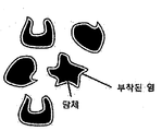
도 2는 본 발명의 일 실시예에 따른 축열재를 도식적으로 나타낸 것이다.
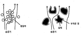
도 3은 염 분말과 본 발명의 일 실시예에 따른 축열재에 있어서 습공기의 이동경로를 나타낸 모식도이다.
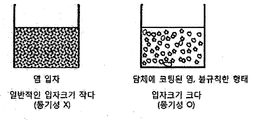
도 4는 염 분말과 본 발명의 일 실시예에 따른 축열재가 반응기에 충진된경우를 나타낸 모식도이다.
도 5는 염 분말(TC2)과 본 발명의 일 실시예에 따른 축열재(TC1)의 수화반응의 시간에 따른 온도의 변화를 각각 나타낸 그래프이다.
이하, 본 발명이 속하는 기술 분야에서 통상의 지식을 가진 자가 용이하게 실시할 수 있도록 본 발명의 실시예에 대하여 첨부한 도면을 참고로 하여 상세히 설명한다. 그러나 본 발명은 여러 가지 상이한 형태로 구현될 수 있으며 여기에서 설명하는 실시예에 한정되지 않는다.
제조예: 축열재의 제조
도 1을 참조하여 축열재의 제조하는 일 실시예에 대하여 설명한다.
우선 용매로 증류수와 염 분말로 염화칼슘 무수물(CaCl2 Anhydrous)을 준비하였다. 상기 증류수 200 g과 상기 염화칼슘 무수물 600 g을 혼합하여 도 1의 두 번째 상태와 같이 농도가 75% 인 염 수용액을 제조하였다.
다음으로, 다공성 담체로서 펄라이트를 준비하여, 이를 도 1의 세 번째 상태와 같이 상기 염 수용액에 담지 하였다. 이후, 약 100℃로 상기 염 수용액을 가열하여 물을 모두 증발시킨 후, 약 120℃의 열풍을 이용하여 펄라이트에 함침된 염을 무수 상태로 만들어 도 1의 네 번째 상태와 같은 축열재를 제조하였다.
도 2 및 3을 참조하면, 펄라이트의 불규칙한 형상으로 인해 습공기를 비롯한 수분과 접촉할 수 있는 면적이 일반 염 분말에 비하여 상당히 넓음을 확인할 수 있으며, 뭉쳐진 염 분말에 비하여 불규칙한 형태인 펄라이트에 함침된 염의 경우가 습공기의 경로 형성이 원활하고 통기성이 우수하여, 수화반응에 더 유리하며 균일한 반응을 유도할 수 있다는 것을 확인할 수 있다.
실시예: 축열재를 이용한 수화반응
발열물질로 상기 제조예에서 제조한 축열재를 반응기에 투입하였다. 여기에 온도가 약 30℃이고, 수증기를 약 70%로 포함하는 공기를 투입해주면서, 상기 축열재의 수화반응을 유도하였다. 상기 수화반응에 제공된 물은 약 70 g이었다. 상기 반응기 내에 습공기를 제공한 시점으로부터 반응기 내의 공기의 온도가 상승하고 그 온도가 유지되는 것을 측정하여 그 결과를 표 1과 도 5에 나타냈다.
비교예: CaCl
2
무수물을 이용한 수화반응
발열물질로 CaCl2 무수물 600 g을 반응기에 투입한 것 외에는 상기 실시예와 동일하게 수화반응을 유도하였다. 상기 반응기 내에 습공기를 제공한 시점으로부터 반응기 내의 공기의 온도가 상승하고 그 온도가 유지되는 것을 측정하여 그 결과를 표 1과 도 5에 나타냈다.
표 1
| 최대온도 상승량 | 최대온도 도달 소요시간 | 온도 유지시간 | |
| 실시예 (축열재) | 40℃ 이상 | 10 분 | 70 분 |
| 비교예 (CaCl2무수물) | 11℃ 이상 | 15 분 | 60 분 |
표 1과 도 5를 참조하면, 비교예(TC2)의 경우, 15 분 후에 반응기 내의 온도가 약 11℃ 정도 상승하였고, 이렇게 상승된 온도가 약 60 분 이상 유지됨을 확인할 수 있는 반면, 실시예(TC1)의 경우, 10 분 이내에 반응기 내의 온도가 약 40℃ 이상 상승하였고, 이렇게 상승된 온도가 약 70 분 이상 약 32 ℃ 이상으로 유지됨을 확인할 수 있었다. 이를 통해, 발열물질로서 축열재를 사용할 경우, 난방 효율이 증대됨을 확인할 수 있다.
이와 같이 축열재를 사용하였을 때에 최대온도에 도달하는 데에 소요된 시간이 더 짧고, 최대온도 상승량도 더욱 큰 것은 도 4에 도시된 바와 같이, 일반 염 입자에 비하여 축열재가 통기성이 좋고 입자크기가 크기 때문임을 확인할 수 있다.
이상에서 본 발명의 바람직한 실시예에 대하여 상세하게 설명하였지만 본 발명의 권리범위는 이에 한정되는 것은 아니고 다음의 청구범위에서 정의하고 있는 본 발명의 기본 개념을 이용한 당업자의 여러 변형 및 개량 형태 또한 본 발명의 권리범위에 속하는 것이다.
Claims (8)
- 다공성 담체; 및 상기 다공성 담체에 함침된 염;을 포함하고, 수화열 에너지가 저장된 축열재.
- 제1항에 있어서,상기 다공성 담체는 비표면적이 0.001 내지 10.0 m2/g인 축열재.
- 제1항에 있어서,상기 염은 염화금속염, 황산금속염, 질산금속염 및 이들의 조합으로 이루어진 군에서 선택된 어느 하나인 것인 축열재.
- 제1항에 있어서,상기 축열재는 가습에 의해 수화열이 발생되어 저장된 수화열 에너지가 낮아지는 것인 축열재.
- 제4항에 있어서,상기 축열재의 낮아진 수화열 에너지는 가열 탈수에 의해 회복되는 것인 축열재.
- 제5항에 있어서,상기 가열 탈수반응은 태양열, 폐열 및 이들의 조합으로 이루어진 군에서 선택된 어느 하나의 열에 의해 수행되는 것인 축열재.
- 제1항에 있어서,상기 축열재는 평균 겉보기 직경이 0.5 mm 내지 50 mm인 것을 포함하는 축열재.
- 제1항에 있어서,상기 축열재는 블록, 벌집 및 이들의 조합으로 이루어진 군에서 선택된 어느 하나의 형태인 것인 축열재.
Applications Claiming Priority (2)
| Application Number | Priority Date | Filing Date | Title |
|---|---|---|---|
| KR10-2014-0085377 | 2014-07-08 | ||
| KR1020140085377A KR101594438B1 (ko) | 2014-07-08 | 2014-07-08 | 수화열 에너지 저장용 축열재 및 이의 제조방법 |
Publications (1)
| Publication Number | Publication Date |
|---|---|
| WO2016006768A1 true WO2016006768A1 (ko) | 2016-01-14 |
Family
ID=55064379
Family Applications (1)
| Application Number | Title | Priority Date | Filing Date |
|---|---|---|---|
| PCT/KR2014/010639 Ceased WO2016006768A1 (ko) | 2014-07-08 | 2014-11-06 | 수화열 에너지 저장용 축열재 및 이의 제조방법 |
Country Status (2)
| Country | Link |
|---|---|
| KR (1) | KR101594438B1 (ko) |
| WO (1) | WO2016006768A1 (ko) |
Cited By (2)
| Publication number | Priority date | Publication date | Assignee | Title |
|---|---|---|---|---|
| CN117511510A (zh) * | 2022-07-27 | 2024-02-06 | 山西大同大学 | 一种生物炭基金属盐复合热能转化材料及其制备方法与应用 |
| CN119709138A (zh) * | 2024-12-20 | 2025-03-28 | 南京工业大学 | 一种硫酸镁/硅藻土复合热化学储热材料制备方法 |
Families Citing this family (1)
| Publication number | Priority date | Publication date | Assignee | Title |
|---|---|---|---|---|
| KR102031059B1 (ko) * | 2017-09-15 | 2019-11-08 | 한국에너지기술연구원 | 태양열 집열기 및 이를 이용한 제습환기장치 및 방법 |
Citations (5)
| Publication number | Priority date | Publication date | Assignee | Title |
|---|---|---|---|---|
| US4273667A (en) * | 1978-11-10 | 1981-06-16 | The Calor Group Limited | Thermal energy storage material comprising hydrated compound and water-swollen cross-linked polymer |
| US4537695A (en) * | 1982-02-23 | 1985-08-27 | Malcolm Hawe | Thermal energy storage compositions |
| JP3033041B2 (ja) * | 1990-06-15 | 2000-04-17 | インスティチュート カタリザ シビルスコゴ オトデレニア ロッシイスコイ アカデミイ ナウク | 蓄熱性材料およびその使用 |
| KR20070029311A (ko) * | 2005-09-09 | 2007-03-14 | 주식회사 효성 | 다공성 잠열 축열재 및 그 제조 방법 |
| KR20130063465A (ko) * | 2011-12-06 | 2013-06-14 | 한국건설기술연구원 | 상전이를 이용한 열저장 및 열방출 가능한 미세기공을 가진 다공성 매체 및 그의 제조방법 |
Family Cites Families (1)
| Publication number | Priority date | Publication date | Assignee | Title |
|---|---|---|---|---|
| JPS61238412A (ja) * | 1985-04-15 | 1986-10-23 | Mitsubishi Electric Corp | 圧延機における形状操作量設定値の決定装置 |
-
2014
- 2014-07-08 KR KR1020140085377A patent/KR101594438B1/ko not_active Expired - Fee Related
- 2014-11-06 WO PCT/KR2014/010639 patent/WO2016006768A1/ko not_active Ceased
Patent Citations (5)
| Publication number | Priority date | Publication date | Assignee | Title |
|---|---|---|---|---|
| US4273667A (en) * | 1978-11-10 | 1981-06-16 | The Calor Group Limited | Thermal energy storage material comprising hydrated compound and water-swollen cross-linked polymer |
| US4537695A (en) * | 1982-02-23 | 1985-08-27 | Malcolm Hawe | Thermal energy storage compositions |
| JP3033041B2 (ja) * | 1990-06-15 | 2000-04-17 | インスティチュート カタリザ シビルスコゴ オトデレニア ロッシイスコイ アカデミイ ナウク | 蓄熱性材料およびその使用 |
| KR20070029311A (ko) * | 2005-09-09 | 2007-03-14 | 주식회사 효성 | 다공성 잠열 축열재 및 그 제조 방법 |
| KR20130063465A (ko) * | 2011-12-06 | 2013-06-14 | 한국건설기술연구원 | 상전이를 이용한 열저장 및 열방출 가능한 미세기공을 가진 다공성 매체 및 그의 제조방법 |
Cited By (2)
| Publication number | Priority date | Publication date | Assignee | Title |
|---|---|---|---|---|
| CN117511510A (zh) * | 2022-07-27 | 2024-02-06 | 山西大同大学 | 一种生物炭基金属盐复合热能转化材料及其制备方法与应用 |
| CN119709138A (zh) * | 2024-12-20 | 2025-03-28 | 南京工业大学 | 一种硫酸镁/硅藻土复合热化学储热材料制备方法 |
Also Published As
| Publication number | Publication date |
|---|---|
| KR101594438B1 (ko) | 2016-02-17 |
| KR20160006040A (ko) | 2016-01-18 |
Similar Documents
| Publication | Publication Date | Title |
|---|---|---|
| Aydin et al. | Novel “open-sorption pipe” reactor for solar thermal energy storage | |
| US11029099B2 (en) | System and method for thermochemical storage of energy | |
| WO2016006768A1 (ko) | 수화열 에너지 저장용 축열재 및 이의 제조방법 | |
| US11709023B2 (en) | Enhanced TCM production and use | |
| CN102527199A (zh) | 一种电渗再生固体除湿方法和装置 | |
| CN110849136A (zh) | 一种热风干燥系统 | |
| CN102532537A (zh) | 一种利用路易斯酸催化制备有机多孔材料方法 | |
| CN113745609B (zh) | 一种从空气中取水的自产氢发电装置 | |
| CN119231061A (zh) | 集成可燃气体调控的电池防护板及其制备方法和电池模组 | |
| CN104654845A (zh) | 固体粒块重力热管蓄热器 | |
| Fan et al. | Form‐stable phase‐change materials supported by 1‐octadecylamine‐modified montmorillonite for latent heat storage | |
| CN104125730A (zh) | 可再生金属基固体干燥剂防凝露机柜及设备 | |
| CN110880629A (zh) | 一种石墨烯辅助相变材料散热的电池组装置 | |
| CN105043148A (zh) | 一种电热蓄能容器 | |
| CN108048046A (zh) | 以泡沫铜为基体的复合相变材料及其制备方法与蓄热包 | |
| CN206240266U (zh) | 活性炭吸附蒸汽再生设备 | |
| CN104654847A (zh) | 一种流体热管蓄热器及蓄热车 | |
| CN213434504U (zh) | 一种可再生干燥装置 | |
| CN104654844A (zh) | 一种流体三腔热管蓄热器及蓄热车 | |
| EP4265995B1 (en) | A component for a thermal system comprising calcium lactate for thermochemical heat accumulation | |
| CN205002646U (zh) | 一种电热蓄能容器 | |
| CA2328351A1 (en) | System for thermo-chemical accumulation of heat | |
| KR101598419B1 (ko) | 난방기를 이용한 난방 방법 및 재사용이 가능한 난방기 | |
| CN104654871A (zh) | 固体粒块循环热管蓄热器 | |
| Aristov et al. | Composite sorbents" calcium chloride inside alumina and carbon mesopores" for thermochemical energy storage. |
Legal Events
| Date | Code | Title | Description |
|---|---|---|---|
| 121 | Ep: the epo has been informed by wipo that ep was designated in this application |
Ref document number: 14897266 Country of ref document: EP Kind code of ref document: A1 |
|
| NENP | Non-entry into the national phase |
Ref country code: DE |
|
| 122 | Ep: pct application non-entry in european phase |
Ref document number: 14897266 Country of ref document: EP Kind code of ref document: A1 |