WO2015198607A1 - Variable barrier pitch correction - Google Patents
Variable barrier pitch correction Download PDFInfo
- Publication number
- WO2015198607A1 WO2015198607A1 PCT/JP2015/003206 JP2015003206W WO2015198607A1 WO 2015198607 A1 WO2015198607 A1 WO 2015198607A1 JP 2015003206 W JP2015003206 W JP 2015003206W WO 2015198607 A1 WO2015198607 A1 WO 2015198607A1
- Authority
- WO
- WIPO (PCT)
- Prior art keywords
- display
- image
- parallax optic
- pixel
- pixels
- Prior art date
- Legal status (The legal status is an assumption and is not a legal conclusion. Google has not performed a legal analysis and makes no representation as to the accuracy of the status listed.)
- Ceased
Links
Images




Classifications
-
- H—ELECTRICITY
- H04—ELECTRIC COMMUNICATION TECHNIQUE
- H04N—PICTORIAL COMMUNICATION, e.g. TELEVISION
- H04N13/00—Stereoscopic video systems; Multi-view video systems; Details thereof
- H04N13/30—Image reproducers
- H04N13/302—Image reproducers for viewing without the aid of special glasses, i.e. using autostereoscopic displays
- H04N13/31—Image reproducers for viewing without the aid of special glasses, i.e. using autostereoscopic displays using parallax barriers
-
- G—PHYSICS
- G02—OPTICS
- G02B—OPTICAL ELEMENTS, SYSTEMS OR APPARATUS
- G02B30/00—Optical systems or apparatus for producing three-dimensional [3D] effects, e.g. stereoscopic images
- G02B30/20—Optical systems or apparatus for producing three-dimensional [3D] effects, e.g. stereoscopic images by providing first and second parallax images to an observer's left and right eyes
- G02B30/26—Optical systems or apparatus for producing three-dimensional [3D] effects, e.g. stereoscopic images by providing first and second parallax images to an observer's left and right eyes of the autostereoscopic type
-
- G—PHYSICS
- G02—OPTICS
- G02B—OPTICAL ELEMENTS, SYSTEMS OR APPARATUS
- G02B30/00—Optical systems or apparatus for producing three-dimensional [3D] effects, e.g. stereoscopic images
- G02B30/20—Optical systems or apparatus for producing three-dimensional [3D] effects, e.g. stereoscopic images by providing first and second parallax images to an observer's left and right eyes
- G02B30/26—Optical systems or apparatus for producing three-dimensional [3D] effects, e.g. stereoscopic images by providing first and second parallax images to an observer's left and right eyes of the autostereoscopic type
- G02B30/27—Optical systems or apparatus for producing three-dimensional [3D] effects, e.g. stereoscopic images by providing first and second parallax images to an observer's left and right eyes of the autostereoscopic type involving lenticular arrays
-
- G—PHYSICS
- G02—OPTICS
- G02B—OPTICAL ELEMENTS, SYSTEMS OR APPARATUS
- G02B30/00—Optical systems or apparatus for producing three-dimensional [3D] effects, e.g. stereoscopic images
- G02B30/20—Optical systems or apparatus for producing three-dimensional [3D] effects, e.g. stereoscopic images by providing first and second parallax images to an observer's left and right eyes
- G02B30/26—Optical systems or apparatus for producing three-dimensional [3D] effects, e.g. stereoscopic images by providing first and second parallax images to an observer's left and right eyes of the autostereoscopic type
- G02B30/27—Optical systems or apparatus for producing three-dimensional [3D] effects, e.g. stereoscopic images by providing first and second parallax images to an observer's left and right eyes of the autostereoscopic type involving lenticular arrays
- G02B30/28—Optical systems or apparatus for producing three-dimensional [3D] effects, e.g. stereoscopic images by providing first and second parallax images to an observer's left and right eyes of the autostereoscopic type involving lenticular arrays involving active lenticular arrays
-
- G—PHYSICS
- G02—OPTICS
- G02B—OPTICAL ELEMENTS, SYSTEMS OR APPARATUS
- G02B30/00—Optical systems or apparatus for producing three-dimensional [3D] effects, e.g. stereoscopic images
- G02B30/20—Optical systems or apparatus for producing three-dimensional [3D] effects, e.g. stereoscopic images by providing first and second parallax images to an observer's left and right eyes
- G02B30/26—Optical systems or apparatus for producing three-dimensional [3D] effects, e.g. stereoscopic images by providing first and second parallax images to an observer's left and right eyes of the autostereoscopic type
- G02B30/30—Optical systems or apparatus for producing three-dimensional [3D] effects, e.g. stereoscopic images by providing first and second parallax images to an observer's left and right eyes of the autostereoscopic type involving parallax barriers
- G02B30/31—Optical systems or apparatus for producing three-dimensional [3D] effects, e.g. stereoscopic images by providing first and second parallax images to an observer's left and right eyes of the autostereoscopic type involving parallax barriers involving active parallax barriers
-
- H—ELECTRICITY
- H04—ELECTRIC COMMUNICATION TECHNIQUE
- H04N—PICTORIAL COMMUNICATION, e.g. TELEVISION
- H04N13/00—Stereoscopic video systems; Multi-view video systems; Details thereof
- H04N13/30—Image reproducers
- H04N13/302—Image reproducers for viewing without the aid of special glasses, i.e. using autostereoscopic displays
- H04N13/305—Image reproducers for viewing without the aid of special glasses, i.e. using autostereoscopic displays using lenticular lenses, e.g. arrangements of cylindrical lenses
-
- H—ELECTRICITY
- H04—ELECTRIC COMMUNICATION TECHNIQUE
- H04N—PICTORIAL COMMUNICATION, e.g. TELEVISION
- H04N13/00—Stereoscopic video systems; Multi-view video systems; Details thereof
- H04N13/30—Image reproducers
- H04N13/366—Image reproducers using viewer tracking
- H04N13/373—Image reproducers using viewer tracking for tracking forward-backward translational head movements, i.e. longitudinal movements
-
- H—ELECTRICITY
- H04—ELECTRIC COMMUNICATION TECHNIQUE
- H04N—PICTORIAL COMMUNICATION, e.g. TELEVISION
- H04N13/00—Stereoscopic video systems; Multi-view video systems; Details thereof
- H04N13/30—Image reproducers
- H04N13/366—Image reproducers using viewer tracking
- H04N13/376—Image reproducers using viewer tracking for tracking left-right translational head movements, i.e. lateral movements
-
- H—ELECTRICITY
- H04—ELECTRIC COMMUNICATION TECHNIQUE
- H04N—PICTORIAL COMMUNICATION, e.g. TELEVISION
- H04N13/00—Stereoscopic video systems; Multi-view video systems; Details thereof
- H04N13/30—Image reproducers
- H04N13/398—Synchronisation thereof; Control thereof
Definitions
- This invention relates to a multiple view directional display such as an autostereoscopic (glasses-free) 3D system that can maintain a 3D effect as a user moves closer to or further from the display.
- the invention is compatible with parallax barrier and lenticular lens systems.
- the invention could be used in other applications, for example to display different 2D content to multiple different users in the manner of commercial ‘Dual View’ displays.
- An autostereoscopic display is a display that gives stereoscopic depth without the user needing to wear glasses. This is accomplished by projecting a different image to each eye.
- An autostereoscopic 3D display can be realised by using parallax optic technology such as a parallax barrier or lenticular lenses.
- parallax barrier technology for viewing 3D images is well described in a paper from the University of Tokushima Japan (“Optimum parameters and viewing areas of stereoscopic full colour LED display using parallax barrier”, Hirotsugu Yamamoto et al., IEICE trans electron, vol E83-c no 10 Oct 2000).
- Figure 1 shows the basic design and operation of parallax barrier technology for use in conjunction with an image display for creating a 3D display.
- the images for the left eye and right eye are interlaced on alternate columns of pixels of the image display.
- the slits in the parallax barrier allow the viewer to see only left image pixels from the position of their left eye and right image pixels from the position of their right eye.
- a fixed parallax barrier or lens system has the disadvantage that the viewer observes a stereoscopic image only in strict viewing zones. Outside these zones, pixel information intended for the left eye may reach the right eye and vice versa.
- Figure 2 (a) shows how the user can see the correct image
- Figure 2 (b) shows the result of the user moving their head laterally (while keeping at the same distance from the display) is that the user sees a pseudoscopic image where each eye sees light from the wrong pixel regions.
- the system can be adjusted in order to change the size and position of the viewing zones. These improvements can be achieved by changing the pixel values, or by changing the barrier parameters or a combination of both.
- Electrical tracking such as discussed in EP0860729-B1, may be achieved by using a parallax barrier composed from a liquid crystal, and electrically addressing it in order to spatially change its transmission properties.
- a parallax barrier composed from a liquid crystal, and electrically addressing it in order to spatially change its transmission properties.
- Such a barrier has certain advantages: it involves no moving parts, and it may be switched into a transmissive state in order to give a full resolution 2D mode.
- This approach is not without drawbacks: making a high quality switchable LC barrier is technically very challenging.
- the shutter must be controllable on a scale smaller than the display’s pixels, which is technically complex.
- the shutter should not include any opaque features which might cause Moire problems with the underlying display. Discrete switching of an electronic barrier causes problems with the brightness uniformity of the resulting image.
- Tracking pixel values underneath a stationary lens or barrier offers some attractive advantages over tracking barrier designs. Since a tracking barrier is not required the system may be simpler and cheaper - a printed parallax barrier of transmissive and opaque features can be used instead of an expensive and complex optical tracking system.
- the tracking speed of the system depends significantly on the speed of the image display, but mobile displays designed for video content already run at fast frame rates. Tracked pixel systems can be scaled up to large display sizes much more easily than tracked barrier type displays can be.
- a conventional autostereoscopic display thus has a designed viewing distance, such that an observer perceives the best 3-D effect when they are at the designed viewing distance - and if the observer moves closer to, or moves further away from, the display the 3-D image quality is degraded.
- the optimum viewing distance of the display may then be changed, so as to be made equal or substantially equal to the current distance between the display and the observer. This ensures that the observer perceives a high quality 3-D image even though the separation between the observer and the display does not stay constant.
- the barrier pitch must be changed, or the positions (relative to the barrier) of images on the display pixels must be changed by re-assigning the pixel values (that is, re-assigning the data value supplied to the pixels of the display), or some hybrid solution must be used.
- the optimum viewing distance must be adjusted through a re-assignment of the pixel values.
- the inventors have recently developed a new tracking system suitable for high quality z-tracking. They have developed two methods for calculating the correct display pixel pattern that allows a non-integer pixel interlace value to be mapped to an integer number of pixels to obtain good viewing properties when using a fixed barrier pitch display. These methods could also be used to calculate optimum barrier pitch parameters in a case where the barrier is reconfigurable and the pixel assignment is fixed, or to calculate hybrid system parameters in a case where the barrier and the pixel assignment are both reconfigurable.
- Approach 1 use a geometrical analysis to calculate a non-integer subpixel repeat unit for interlacing.
- interlacing starts at a point determined by the user’s head position relative to the display.
- the non-integer number ensures that the interlace pattern inserts extra pixels where necessary in order to compensate for the user’s head position.
- the use of a non-integer interlacing pattern has not been previously reported.
- Approach 2 use a pixel-by-pixel calculation step, whereby every pixel’s position relative to the user’s eyes and the nearest slit of the barrier determines whether the pixel should show left-view or right-view information. This approach may be done for blocks of pixels, but performance is optimal when calculated on a pixel-by-pixel basis.
- these approaches can also be used to calculate parameter values for tracked barrier systems, or hybrid tracked pixel and barrier systems.
- the first aspect of the invention may for example be applied with a fixed (that is, non-reconfigurable) parallax optic, to determine pixels that should display the first image and to determine pixels that should display the second image (for example to determine pixels that should display a left eye image and to determine pixels that should display a right eye image, to provide a 3-D autostereoscopic image to the observer).
- This aspect may be used to implement z-tracking, by, as the observer moves towards or away from the barrier, recalculating which pixels should display the left-eye image and which pixels should display the right eye image and re-addressing the image display layer accordingly so that the observer continues to see a good-quality 3-D image.
- the method may comprise determining a desired location and size for one or more opaque barrier regions of the parallax optic.
- This method is generally complementary to the first aspect, but may be applied to a display having a reconfigurable parallax optic to determine a configuration for the parallax optic of the display based on the distance between the display and the observer.
- This aspect may be used to implement z-tracking, by, as the observer moves towards or away from the barrier, reconfiguring the parallax optic so that the observer continues to see a good-quality 3-D image.
- a re-configurable parallax optic is meant that the parallax optic may be re-configured to vary the position and/or size of the elements of the parallax optic.
- a parallax barrier embodied as a liquid crystal panel, when the position and/or size of the opaque and transmissive regions of the parallax barrier may be varied by suitably addressing the liquid crystal panel.
- a third aspect of the invention provides method of displaying a multiple view image comprising: determining, based on the distance of an observer from a multiple view directional display having an image display layer and a parallax optic, the width of a projection of an element of the parallax optic onto the image display layer; determining a pixel interlace value from the width of the projection of the element of the parallax optic onto the image display layer; and assigning a pixel with data corresponding to a first image or with data corresponding to a second image in accordance with the determined pixel interlace value.
- the third aspect of the invention may for example be applied with a fixed (that is, non-reconfigurable) parallax optic, to determine a pixel interlace value based on the distance of the observer from the display pixels and addressing the image display layer to obtain the calculated pixel interlace value or a value close thereto.
- This aspect may be used to implement z-tracking, by, as the observer moves towards or away from the barrier, recalculating the pixel interlace value and addressing the image display layer to obtain the recalculated pixel interlace value, or a value close thereto, so that the observer continues to see a good-quality 3-D image.
- a fourth aspect of the invention provides a method of displaying a multiple view image comprising: determining a desired projection of an element of a re-configurable parallax optic of a multiple view directional display having an image display layer and the parallax optic based on a desired pixel interlace value; determining a desired size for the element of the parallax optic, from the desired projection of the element; and addressing the parallax optic to obtain an element of the desired size.
- the fourth aspect is generally complementary to the third aspect, but may be applied to a display having a reconfigurable parallax optic to determine a configuration for the parallax optic of the display based on the distance between the display and the observer.
- This aspect may be used to implement z-tracking, by, as the observer moves towards or away from the barrier, reconfiguring the parallax optic so that the observer continues to see a good-quality 3-D image.
- a method of the first or third aspect may be applied with a multiple view directional display having any form of parallax optic, such as, for example, a parallax barrier aperture array or a lenticular parallax optic.
- a method of the second or fourth aspect may be applied with a multiple view directional display having any form of re-configurable parallax optic, such as, for example, a re-configurable parallax barrier aperture array.
- a fifth aspect of the invention provides a multiple view directional display configured to perform a method of the first, second or third aspect.
- a sixth aspect of the invention provides a multiple view directional display comprising: an image display panel; a parallax optic; an observer tracking unit; and a control unit, the control unit adapted to perform a method of the first, second, third or fourth aspect.
- a seventh aspect of the invention provides a multiple view directional display comprising: an image display panel; a parallax optic; an observer tracking unit; and a control unit, the control unit adapted to assign data values to pixels of the image display panel such as to provide an interlacing pattern of a first image and a second image having a repeat length that is a non-integer number of pixels.
- a non-integer NP interlace value makes it possible to provide good image quality even if the observer(s) move away from, or closer to, the display.
- the motivation for tracking is to know the position of the user’s left and right eyes. This information can then be used to display image data, and/or change the optical properties of the system, such that each eye is shown a different image and the user experiences stereoscopic 3D even though the user is moving relative to the display.
- the inventors have developed two new methods for calculating positions of optical elements in the display relative to the user and appropriately updating the display system.
- the invention may be used to calculate the pixel affinity (that is, whether a pixel or sub-pixel should display a left eye image or a right eye image) of one or more pixels or sub-pixels in a display having a parallax optic of known configuration, and in this case the display system may be updated by re-assigning pixel values dependent on determined pixel affinity.
- the invention may be used to calculate the positions of elements of the parallax optic (such as the positions of opaque regions of a parallax barrier aperture array) in a display in which the parallax optic can be reconfigured to track the position of an observers moving relative to the display, and/or calculating positions of barrier regions of a parallax barrier in this case the display system may be updated by re-configuring the parallax optic.
- elements of the parallax optic such as the positions of opaque regions of a parallax barrier aperture array
- the first method involves tracing a light ray from each image pixel (or form a block of pixels) to the user’s mid-eye position.
- This light ray intercepts the parallax barrier, or other optical element, at a certain position.
- the distance between this intercept point and the nearest slit on the barrier is determined from the relative positions of the user and display, and from one or more parameters of the display such as refractive indices.
- the one or more parameters of the display comprise a separation between an image display layer of the display and the parallax optic and the ratio between the refractive index of a medium between the image display layer of the display and the parallax optic and the refractive index of a medium between the display and the observer.
- the distance between the intercept point and the closest slit determines whether the light ray, and hence the pixel, is seen by the left or right eye.
- the pixel If the pixel is to be seen by a left eye then it can be loaded with a perspective image suitable for the left eye. If these perspective images are pre-rendered, then the pixel can ‘look up’ the appropriate image data, that is a pre-rendered data value is assigned to the pixel. The process for right eye data is identical.
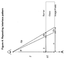
- Figure 3 illustrates how a pixel affinity (that is, whether a pixel should display a left eye image or a right eye image) can be derived from geometric terms.
- the pixel affinity may be derived based on the distance between, on the one hand, the intersection of the ray path (from the pixel to the observer) and the parallax optic and, on the other hand, the nearest aperture of the parallax optic.
- Figure 3(a) is a front plan view of a display
- figure 3(b) is a schematic sectional view of the display showing a parallax barrier separated from a pixelated image display layer by a substrate (in this example a glass substrate).
- the display face of the display is assumed to be in the x-y plane, so that the z-axis extends perpendicularly to the display face of the display.
- the x-axis is shown extending horizontally in figure 3(a) and the y-axis is shown extending vertically in figure 3(a).
- a viewer is positioned such that their mid-eye position is at a distance Z from the front face of the display, and has an x-co-ordinate denoted by X.
- a “barrier intercept” is a point where a ray from a pixel to the viewer’s mid-eye position intercepts the plane of the barrier
- n(repeat) The pixel assignment for any other effective value of n(repeat) can be calculated in an analogous way.
- the interlace fill is preferably done symmetrically, starting at the point in the display that is the closest point on the display to the viewer (point A in figure 4), and working outwards horizontally in both directions from this starting point. (This assumes that the closest point is not at an edge of the display - if the closest point is at an edge of the display the interlace fill is necessarily done working in one direction only - that is, the interlace fill is not done symmetrically.
- the pixels would need to be re-assigned between the left eye image and the right-eye image to ensure that the user continued to perceive a good quality 3-D image - the pixel reassignment would be done keeping the same interlace repeat, but starting the fill at the position on the display closest to the viewer’s new location.
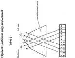
- Figure 8 illustrates an NP6-3 system where an element of the parallax optic comprises a multi-faceted lens, with the lens configured such that a first set of sub-pixels (or pixels) with a width of 3 columns of sub-pixels (or pixels) is visible to the viewer’s left eye, while a second set of sub-pixels (or pixels), which is different to the first set, with a width of 3 columns of sub-pixels (or pixels) is visible to a viewer’s right eye.
- the first [second] set of sub-pixels (or pixels) visible to the viewer’s left [right] eye may comprise 3 or 4 sub-pixels (or pixels) but the region of the pixelated display visible to the viewer’s left [right] eye always has a width equal to 3 sub-pixels (or pixels),
- the left eye image is addressed to the first 6 sub-pixels (or pixels) shown in figure 8 (labelled 1 to 6) and the right eye image is addressed to the next 6 sub-pixels (or pixels).
- sub-pixel (or pixel) 1 is not visible to the viewer
- half of sub-pixel (or pixel) 2 is visible to the viewer’s left eye
- all of sub-pixel (or pixel) 3 is visible to the viewer’s left eye
- all of sub-pixel (or pixel) 4 is visible is the viewer’s left eye
- half of sub-pixel (or pixel) 5 is visible to the viewer’s left eye 21
- sub-pixel (or pixel) 6 is not visible to the viewer.
- the width of the display visible to the viewer’s left eye is exactly 3 sub-pixels (or pixels) - the width visible being equal to half the width of L2 + the width of L3 + the width of L4 + half the width of L5.
- the width of the display visible to the viewer’s right eye 22 is exactly 3 sub-pixels (or pixels) and comprises half the width of the eighth sub-pixel (or pixel) + the width of the ninth sub-pixel (or pixel) + the width of the tenth sub-pixel (or pixel) + half the width of the eleventh sub-pixel (or pixel).
- a different set of sub-pixels (or pixels) are visible to the viewer’s left eye - for example half the width of L1 + the width of L2 + the width of L3 + half the width of L4.
- the width of the display visible to the viewer’s right eye is again exactly 3 sub-pixels (or pixels) and comprises half the width of the seventh sub-pixel (or pixel) + the width of the eighth sub-pixel (or pixel) + the width of the ninth sub-pixel (or pixel) R9 + half the width of the tenth sub-pixel (or pixel).
- a third head position whereby exactly 3 sub-pixels (or pixels) are visible to the viewer’s left eye (L2, L3 and L4) and exactly 3 sub pixels (or pixels) are visible to the viewer’s right eye (the eighth, ninth and tenth sub-pixels (or pixels).
- the invention offers numerous advantages over previous tracking systems.
- the primary advantage is the increased z-freedom over fixed-width interlacing systems.
- a second advantage is ability of the system to work with printed parallax barriers allowing 3D technology to be implemented inexpensively.
- the lack of moving parts adds the potential for increased robustness and decreased complexity compared with mechanical tracking systems.
- the ability to change the effective barrier pitch correction gives better off-axis properties, and the ability to dynamically adjust the optimum viewer position to match the user. This allows the display to be re-positioned relative to the user, or even tiled to give a high quality multi-display system.
- EMBODIMENTS 1.
- the tracking system is used in conjunction with a camera and fixed parallax barrier 3D display.
- a parallax system with a 6 sub-pixel repeating interlace pattern, a slanted barrier with a slope of 1 pixel per row and a slit width of 3 pixels (NP6-3 stag1) gives very good tracking performance.
- This good performance is partly due to the ‘redundant’ sub-pixels that are initially hidden from the user and may be pre-loaded with view information. Correct view information can be maintained for each eye as the user moves and these hidden sub-pixels are revealed.
- the image processing hardware is configured to implement method one and/or method two as described above. 2.
- the tracking system is used in with a camera and a switchable parallax barrier.
- the barrier may be switchable in a discrete manner, as illustrated by Figure 5c, with electrodes used to control spatial transmissivity.
- the barrier features can then be moved to track the position of the user.
- Such a parallax barrier may be switched into a transmissive mode so that the full resolution of the base panel is seen in 2D.
- Such a system may also give brightness advantages over a fixed barrier design.
- Z tracking can be achieved by changing the display image, changing the width of barrier region and slits across the display (so as to adjust the pitch of the parallax barrier) or a hybrid approach. Possible display constructions that allow for varying barrier pitch are illustrated in Figure 6a-d.
- Figures 6a and 6b are a plan view and a sectional view of one display that allows for varying barrier pitch.
- the display has an image display panel in which independently addressable pixels are provided between a TFT substrate and a colour filter substrate - the image display panel may be conventional, and will not be described further.
- the display also has a parallax barrier panel, in which regions of a medium (for example a liquid crystal or other electro-optic material) disposed between an SEG (“segmented electrode”) substrate and a COM (“common electrode”) substrate may be addressed by means of independently addressable electrodes E(1)...E(8) disposed on the SEG substrate and a planar electrode on the COM substrate as shown in figure 6(b).
- a medium for example a liquid crystal or other electro-optic material
- FIG. 6(b) illustrates the electrodes of the parallax barrier panel being addressed such that the regions of the medium opposite electrodes E(1), E(2), and E(6)-E(8) are opaque to define barrier regions while the regions of the medium opposite electrodes E(3) - E(5) are transmissible to define slits.
- the display of figures 6(c) and 6(d) is generally similar to that of figures 6(a) and 6(b), except that, instead of a planar electrode, individually addressable electrodes E(9) - E (16) are provided on the COM substrate.
- the electrodes E(9) - E (16) on the COM substrate are offset with respect to the electrodes E(1) - E (8) on the SEG substrate, and this allows finer control of the positions and widths of the barrier regions and slits.
- the COM substrate is not provided with a common electrode per se, but instead is provided with segmented electrodes E(9)...E(16), unlike figure 6(b) where a single, continuous planar electrode is provided on the COM substrate.
- FIG. 6(d) illustrates a common electrode substrate, which is a general term in TFT displays.
- figures 6(a-d) illustrate parallax barrier panels with 8 and 16 electrodes, it is possible to construct a parallax barrier with other numbers of electrodes as well.
- Individual electrodes require more complex control circuitry including more connections, Figure 7a. As the number of electrodes increases it may become necessary to put control circuitry directly onto the substrate, Figure 7b, as is currently done with mobile LCD display control systems. 4.
- the tracking system is used with a camera and a parallax barrier that is switchable in a continuous manner. 5.
- the system is used with a lens system including lenticular or more sophisticated lens elements.
- a lenticular lens example is shown in Figure 5b and in Figure 8. 6.
- the system is used with a MEMS, photochromic, heat-sensitive, bi-stable, GRIN lens or hybrid system... 7.
- the system is used with a depth sensor being used in place of a camera.
- the determination of the intersection of the ray path and the parallax optic may be based on one or more parameters of the display, and on the relative positions of the observer and the group of pixels.
- the one or more parameters of the display may comprise a separation between an image display layer of the display and the parallax optic and the ratio between the refractive index of a medium between the image display layer of the display and the parallax optic and the refractive index of a medium between the display and the observer.
- a method of the first aspect may comprise assigning pre-rendered data values to the pixels.
- first image data may be rendered for those pixels to be addressed with data relating to the first image
- second image data may be rendered for those pixels to be addressed with data relating to the second image
- a method of the first aspect may further comprise determining, from the intersection of the ray path and the parallax optic, a location and size of one or more elements in the parallax optic - for example determining, the location and size of one or more opaque barrier regions in a case where the parallax optic comprises a parallax barrier array.
- movement of the observer is compensated for both by re-addressing the image display layer and by re-defining the parallax optic.
- the group of pixels may include two or more pixels, that is n>1.
- a method of the third aspect may comprise determining a non-integer pixel interlace value.
- the first image may be a right eye image and the second image may be a left eye image, whereby the multiple view image is an autostereoscopic 3-D image.
- the first and second images may be unconnected images for display to different observers.
- the optimum barrier position is calculated. This is equivalent to determining a “barrier interlace value” in a manner similar to that described in the third embodiment, and then determining whether a barrier region should be opaque or not in accordance with the value.
- a display of the fifth, sixth or seventh aspect may comprise an autostereoscopic display.
- the parallax optic of a display of the fifth, sixth or seventh aspect of the invention may be disableable. This allows the display to operate in a conventional 2-D mode.
- a disableable parallax optic may for example be a parallax barrier aperture array defined in a liquid crystal panel, or a switchable lens array such as a liquid crystal lens array.
- This system could be used to deliver high quality tracked autostereoscopic 3D. Alternatively, it could be used to display different high quality 2D images to multiple viewers.
Landscapes
- Engineering & Computer Science (AREA)
- Multimedia (AREA)
- Signal Processing (AREA)
- Physics & Mathematics (AREA)
- General Physics & Mathematics (AREA)
- Optics & Photonics (AREA)
- Testing, Inspecting, Measuring Of Stereoscopic Televisions And Televisions (AREA)
Abstract
Two methods are described for calculating the non-periodic display pixel pattern necessary for good viewing properties of a multiple view directional display with a fixed parallax barrier pitch. These methods could also be used to calculate optimum barrier pitch parameters for a display with a re-configurable parallax optic, such as a re-configurable parallax barrier, and a fixed pixel assignment, or to calculate hybrid system parameters in a display where the parallax optic (eg a parallax barrier) and the pixel assignment are both re-configurable. The first method uses a geometrical analysis to calculate a non-integer subpixel repeat unit for interlacing. In this approach interlacing starts at a point determined by the user's head position relative to the display. The non-integer number ensures that the interlace pattern inserts extra pixels where necessary in order to compensate for the user's head position. The second method uses a pixel-by-pixel calculation step, whereby every pixel's position relative to the user's eyes and the nearest slit of the barrier determines whether the pixel should show left-view or right-view information. This approach may be done for blocks of pixels, but performance is optimal when calculated on a pixel-by-pixel basis.
Description
This invention relates to a multiple view directional display such as an autostereoscopic (glasses-free) 3D system that can maintain a 3D effect as a user moves closer to or further from the display. The invention is compatible with parallax barrier and lenticular lens systems. The invention could be used in other applications, for example to display different 2D content to multiple different users in the manner of commercial ‘Dual View’ displays.
For many years people have been trying to create better autostereoscopic 3D displays, and this invention provides a further advance in this field. An autostereoscopic display is a display that gives stereoscopic depth without the user needing to wear glasses. This is accomplished by projecting a different image to each eye. An autostereoscopic 3D display can be realised by using parallax optic technology such as a parallax barrier or lenticular lenses.
The design and operation of parallax barrier technology for viewing 3D images is well described in a paper from the University of Tokushima Japan (“Optimum parameters and viewing areas of stereoscopic full colour LED display using parallax barrier”, Hirotsugu Yamamoto et al., IEICE trans electron, vol E83-c no 10 Oct 2000).
Figure 1 shows the basic design and operation of parallax barrier technology for use in conjunction with an image display for creating a 3D display. The images for the left eye and right eye are interlaced on alternate columns of pixels of the image display. The slits in the parallax barrier allow the viewer to see only left image pixels from the position of their left eye and right image pixels from the position of their right eye.
A fixed parallax barrier or lens system has the disadvantage that the viewer observes a stereoscopic image only in strict viewing zones. Outside these zones, pixel information intended for the left eye may reach the right eye and vice versa. Figure 2 (a) shows how the user can see the correct image, and Figure 2 (b) shows the result of the user moving their head laterally (while keeping at the same distance from the display) is that the user sees a pseudoscopic image where each eye sees light from the wrong pixel regions.
By tracking the positions of the user’s eyes, the system can be adjusted in order to change the size and position of the viewing zones. These improvements can be achieved by changing the pixel values, or by changing the barrier parameters or a combination of both.
Mechanical tracking involves physically moving the parallax barrier or optics relative to the pixels and the screen. US6377295 and US5083199 describe how this might be achieved with a lenticular lens system and a parallax barrier system respectively. The authors of US6377295 note that mechanical tracking has drawbacks. Adding a mechanical element to the system is likely to increase the total system cost, whilst the dependence on moving parts could decrease the system robustness. Another concern is that the tracking speed of a mechanical system may not be fast enough to cope with rapid changes in user position.
Electrical tracking, such as discussed in EP0860729-B1, may be achieved by using a parallax barrier composed from a liquid crystal, and electrically addressing it in order to spatially change its transmission properties. Such a barrier has certain advantages: it involves no moving parts, and it may be switched into a transmissive state in order to give a full resolution 2D mode. This approach is not without drawbacks: making a high quality switchable LC barrier is technically very challenging. The shutter must be controllable on a scale smaller than the display’s pixels, which is technically complex. The shutter should not include any opaque features which might cause Moire problems with the underlying display. Discrete switching of an electronic barrier causes problems with the brightness uniformity of the resulting image.
Tracking pixel values underneath a stationary lens or barrier offers some attractive advantages over tracking barrier designs. Since a tracking barrier is not required the system may be simpler and cheaper - a printed parallax barrier of transmissive and opaque features can be used instead of an expensive and complex optical tracking system. The tracking speed of the system depends significantly on the speed of the image display, but mobile displays designed for video content already run at fast frame rates. Tracked pixel systems can be scaled up to large display sizes much more easily than tracked barrier type displays can be.
An early tracked pixel 3D display was disclosed by K Akiyama and N Tetsutani, “3-Dimensional Visual Communication”, ITEC’91, 1991 OTE Annual Convention. In this design, a lenticular lens sheet angularly multiplexes light from adjacent columns of pixels on a display. A position detector monitors the user’s position, causing the display to switch the information displayed on the columns of pixels when the user moves out from the primary viewing window. This system greatly increases head freedom, but introduces a very visible artefact when users switch between viewing windows.
An improved system was disclosed by US5959664, whereby the image display contains right eye data, left eye data and some regions which are not seen by either eye. These redundant regions are extremely important, since they allow for increased tolerance to movement of the observer towards or away from the display (“Z-tolerance”) and smoother tracking. Instead of performing a visible left/right image data swap, the appropriate image data can be loaded into a region not yet visible to the observer. When the observer’s head moves laterally the correct view information may then be seen, allowing for smooth tracking.
Even with these developments, current head tracking 3D technologies are far from perfect. In particular, adjusting for movements of the user towards or away from the display remains a major unsolved problem.
As explained with reference to figure 2, movement of the observer relative to the display in a lateral direction, while maintaining the same separation between the observer and the display, will cause the observer to move from a position at which they perceive a 3-D image to a position at which they do not perceive a 3-D image. However, the spatial regions in which a left eye image or a right eye image is displayed also have a finite extent in the direction perpendicular to the display (this will be taken to be the z-direction). A conventional autostereoscopic display thus has a designed viewing distance, such that an observer perceives the best 3-D effect when they are at the designed viewing distance - and if the observer moves closer to, or moves further away from, the display the 3-D image quality is degraded. When an autostereoscopic display is intended for use in situations where the distance between an observer and the display may vary, it is therefore desirable to track movement of the observer towards or away from the display (“z-tracking”) instead of, or in addition to, tracking lateral movement of the observer with respect to the display.
In a display that uses z-tracking, if it is determined that the distance between the observer and the display has changed significantly the optimum viewing distance of the display may then be changed, so as to be made equal or substantially equal to the current distance between the display and the observer. This ensures that the observer perceives a high quality 3-D image even though the separation between the observer and the display does not stay constant. In order to adjust the optimum viewing distance of a parallax type 3D display, either the barrier pitch must be changed, or the positions (relative to the barrier) of images on the display pixels must be changed by re-assigning the pixel values (that is, re-assigning the data value supplied to the pixels of the display), or some hybrid solution must be used. In a case where the display has a fixed barrier, the optimum viewing distance must be adjusted through a re-assignment of the pixel values.
The inventors have recently developed a new tracking system suitable for high quality z-tracking. They have developed two methods for calculating the correct display pixel pattern that allows a non-integer pixel interlace value to be mapped to an integer number of pixels to obtain good viewing properties when using a fixed barrier pitch display. These methods could also be used to calculate optimum barrier pitch parameters in a case where the barrier is reconfigurable and the pixel assignment is fixed, or to calculate hybrid system parameters in a case where the barrier and the pixel assignment are both reconfigurable.
Approach 1: use a geometrical analysis to calculate a non-integer subpixel repeat unit for interlacing. In this approach interlacing starts at a point determined by the user’s head position relative to the display. The non-integer number ensures that the interlace pattern inserts extra pixels where necessary in order to compensate for the user’s head position. The use of a non-integer interlacing pattern has not been previously reported.
Approach 2: use a pixel-by-pixel calculation step, whereby every pixel’s position relative to the user’s eyes and the nearest slit of the barrier determines whether the pixel should show left-view or right-view information. This approach may be done for blocks of pixels, but performance is optimal when calculated on a pixel-by-pixel basis.
With small adjustments, these approaches can also be used to calculate parameter values for tracked barrier systems, or hybrid tracked pixel and barrier systems.
A first aspect of the invention provides a method of displaying a multiple view image comprising: for a group of n pixels (n = 1, 2, 3…) of an multiple view directional display, determining, based on the distance between the display and an observer, where a ray path from the group of pixels to the observer intersects a parallax optic of the display; determining, from the intersection of the ray path and the parallax optic, whether the group of pixels should display a first image or a second image; and assigning data values to the or each pixel of the group according to the determination whether the group of pixels should be addressed with data relating to the first image or with data relating to the second image.
The first aspect of the invention may for example be applied with a fixed (that is, non-reconfigurable) parallax optic, to determine pixels that should display the first image and to determine pixels that should display the second image (for example to determine pixels that should display a left eye image and to determine pixels that should display a right eye image, to provide a 3-D autostereoscopic image to the observer). This aspect may be used to implement z-tracking, by, as the observer moves towards or away from the barrier, recalculating which pixels should display the left-eye image and which pixels should display the right eye image and re-addressing the image display layer accordingly so that the observer continues to see a good-quality 3-D image.
A second aspect of the invention provides a method of displaying a multiple view image comprising: for a group of n pixels (n = 1, 2, 3…) of a multiple view directional display, determining, based on the distance between the display and an observer, where a ray path from the group of pixels to the observer intersects a re-configurable parallax optic of the display; determining, from the intersection of the ray path and the parallax optic, a desired location and size for one or more elements of the parallax optic; and addressing the parallax optic to define one or more elements in the parallax optic in accordance with the determined location and size. For example, where the parallax optic comprises a parallax barrier array the method may comprise determining a desired location and size for one or more opaque barrier regions of the parallax optic. This method is generally complementary to the first aspect, but may be applied to a display having a reconfigurable parallax optic to determine a configuration for the parallax optic of the display based on the distance between the display and the observer. This aspect may be used to implement z-tracking, by, as the observer moves towards or away from the barrier, reconfiguring the parallax optic so that the observer continues to see a good-quality 3-D image. By a “re-configurable” parallax optic is meant that the parallax optic may be re-configured to vary the position and/or size of the elements of the parallax optic. One example of a re-configurable parallax optic is a parallax barrier embodied as a liquid crystal panel, when the position and/or size of the opaque and transmissive regions of the parallax barrier may be varied by suitably addressing the liquid crystal panel.
A third aspect of the invention provides method of displaying a multiple view image comprising: determining, based on the distance of an observer from a multiple view directional display having an image display layer and a parallax optic, the width of a projection of an element of the parallax optic onto the image display layer; determining a pixel interlace value from the width of the projection of the element of the parallax optic onto the image display layer; and assigning a pixel with data corresponding to a first image or with data corresponding to a second image in accordance with the determined pixel interlace value.
The third aspect of the invention may for example be applied with a fixed (that is, non-reconfigurable) parallax optic, to determine a pixel interlace value based on the distance of the observer from the display pixels and addressing the image display layer to obtain the calculated pixel interlace value or a value close thereto. This aspect may be used to implement z-tracking, by, as the observer moves towards or away from the barrier, recalculating the pixel interlace value and addressing the image display layer to obtain the recalculated pixel interlace value, or a value close thereto, so that the observer continues to see a good-quality 3-D image.
A fourth aspect of the invention provides a method of displaying a multiple view image comprising: determining a desired projection of an element of a re-configurable parallax optic of a multiple view directional display having an image display layer and the parallax optic based on a desired pixel interlace value; determining a desired size for the element of the parallax optic, from the desired projection of the element; and addressing the parallax optic to obtain an element of the desired size.
The fourth aspect is generally complementary to the third aspect, but may be applied to a display having a reconfigurable parallax optic to determine a configuration for the parallax optic of the display based on the distance between the display and the observer. This aspect may be used to implement z-tracking, by, as the observer moves towards or away from the barrier, reconfiguring the parallax optic so that the observer continues to see a good-quality 3-D image.
A method of the first or third aspect may be applied with a multiple view directional display having any form of parallax optic, such as, for example, a parallax barrier aperture array or a lenticular parallax optic. A method of the second or fourth aspect may be applied with a multiple view directional display having any form of re-configurable parallax optic, such as, for example, a re-configurable parallax barrier aperture array.
A fifth aspect of the invention provides a multiple view directional display configured to perform a method of the first, second or third aspect.
A sixth aspect of the invention provides a multiple view directional display comprising: an image display panel; a parallax optic; an observer tracking unit; and a control unit, the control unit adapted to perform a method of the first, second, third or fourth aspect.
A seventh aspect of the invention provides a multiple view directional display comprising: an image display panel; a parallax optic; an observer tracking unit; and a control unit, the control unit adapted to assign data values to pixels of the image display panel such as to provide an interlacing pattern of a first image and a second image having a repeat length that is a non-integer number of pixels. Use of a non-integer NP interlace value makes it possible to provide good image quality even if the observer(s) move away from, or closer to, the display.
The motivation for tracking is to know the position of the user’s left and right eyes. This information can then be used to display image data, and/or change the optical properties of the system, such that each eye is shown a different image and the user experiences stereoscopic 3D even though the user is moving relative to the display. The inventors have developed two new methods for calculating positions of optical elements in the display relative to the user and appropriately updating the display system. The invention may be used to calculate the pixel affinity (that is, whether a pixel or sub-pixel should display a left eye image or a right eye image) of one or more pixels or sub-pixels in a display having a parallax optic of known configuration, and in this case the display system may be updated by re-assigning pixel values dependent on determined pixel affinity. Additionally or alternatively, the invention may be used to calculate the positions of elements of the parallax optic (such as the positions of opaque regions of a parallax barrier aperture array) in a display in which the parallax optic can be reconfigured to track the position of an observers moving relative to the display, and/or calculating positions of barrier regions of a parallax barrier in this case the display system may be updated by re-configuring the parallax optic.
The first method involves tracing a light ray from each image pixel (or form a block of pixels) to the user’s mid-eye position. This light ray intercepts the parallax barrier, or other optical element, at a certain position. The distance between this intercept point and the nearest slit on the barrier is determined from the relative positions of the user and display, and from one or more parameters of the display such as refractive indices. In one example the one or more parameters of the display comprise a separation between an image display layer of the display and the parallax optic and the ratio between the refractive index of a medium between the image display layer of the display and the parallax optic and the refractive index of a medium between the display and the observer. The distance between the intercept point and the closest slit determines whether the light ray, and hence the pixel, is seen by the left or right eye.
If the pixel is to be seen by a left eye then it can be loaded with a perspective image suitable for the left eye. If these perspective images are pre-rendered, then the pixel can ‘look up’ the appropriate image data, that is a pre-rendered data value is assigned to the pixel. The process for right eye data is identical.
Depending on the barrier design, there may be ‘redundant’ regions of pixels which are not seen by either eye. This interlacing method causes them to be loaded with the most appropriate image data and hence allows for smooth tracking. As the user moves, the pre-loaded data becomes visible without any image updating latency or brightness variation.
By running the geometrical calculations as a GPU accelerated shader it is possible to calculate large numbers of pixel affinities in real time.
Figure 3 illustrates how a pixel affinity (that is, whether a pixel should display a left eye image or a right eye image) can be derived from geometric terms. For example the pixel affinity may be derived based on the distance between, on the one hand, the intersection of the ray path (from the pixel to the observer) and the parallax optic and, on the other hand, the nearest aperture of the parallax optic.
Figure 3(a) is a front plan view of a display, and figure 3(b) is a schematic sectional view of the display showing a parallax barrier separated from a pixelated image display layer by a substrate (in this example a glass substrate).
As indicated in figure 3, the display face of the display is assumed to be in the x-y plane, so that the z-axis extends perpendicularly to the display face of the display. For the sake of example the x-axis is shown extending horizontally in figure 3(a) and the y-axis is shown extending vertically in figure 3(a). A viewer is positioned such that their mid-eye position is at a distance Z from the front face of the display, and has an x-co-ordinate denoted by X. As a simplification, it is assumed here that the viewer’s mid-eye position, image pixels and the barrier intercept (a “barrier intercept” is a point where a ray from a pixel to the viewer’s mid-eye position intercepts the plane of the barrier) are all in the same y-plane, and so y-coordinate terms can be omitted.
In figure 3(b), the separation in the z-direction between the image display layer and the barrier is denoted by s, and the separation in the x-direction between a pixel and its corresponding barrier intercept is denoted by d.


In the case of an effective value of n(repeat) of 9/4, the pixel assignment may be calculated as follows:
(9/4) -> rounds to 2,so display 2 pixels as L;
(9/4 + 9/4 = 9/2) -> rounds to 4, so display another (4-2 = 2) pixels as R;
(9/4 + 9/4 + 9/4 = 27/4) -> rounds to 7, so display another (7-4 = 3) pixels as L;
(9/4 + 9/4 + 9/4 + 9/4 = 9), so display (9-7 = 2) pixels as R.
(9/4) -> rounds to 2,so display 2 pixels as L;
(9/4 + 9/4 = 9/2) -> rounds to 4, so display another (4-2 = 2) pixels as R;
(9/4 + 9/4 + 9/4 = 27/4) -> rounds to 7, so display another (7-4 = 3) pixels as L;
(9/4 + 9/4 + 9/4 + 9/4 = 9), so display (9-7 = 2) pixels as R.
The pixel assignment for any other effective value of n(repeat) can be calculated in an analogous way.
The interlace fill is preferably done symmetrically, starting at the point in the display that is the closest point on the display to the viewer (point A in figure 4), and working outwards horizontally in both directions from this starting point. (This assumes that the closest point is not at an edge of the display - if the closest point is at an edge of the display the interlace fill is necessarily done working in one direction only - that is, the interlace fill is not done symmetrically.
If the user were to move laterally with respect to the display the pixels would need to be re-assigned between the left eye image and the right-eye image to ensure that the user continued to perceive a good quality 3-D image - the pixel reassignment would be done keeping the same interlace repeat, but starting the fill at the position on the display closest to the viewer’s new location.

Figure 8 illustrates an NP6-3 system where an element of the parallax optic comprises a multi-faceted lens, with the lens configured such that a first set of sub-pixels (or pixels) with a width of 3 columns of sub-pixels (or pixels) is visible to the viewer’s left eye, while a second set of sub-pixels (or pixels), which is different to the first set, with a width of 3 columns of sub-pixels (or pixels) is visible to a viewer’s right eye. It should be noted that the first [second] set of sub-pixels (or pixels) visible to the viewer’s left [right] eye may comprise 3 or 4 sub-pixels (or pixels) but the region of the pixelated display visible to the viewer’s left [right] eye always has a width equal to 3 sub-pixels (or pixels), With reference to Figure 8, assume that for a first given observers head position the left eye image is addressed to the first 6 sub-pixels (or pixels) shown in figure 8 (labelled 1 to 6) and the right eye image is addressed to the next 6 sub-pixels (or pixels). Also assume that, for this observer head position, sub-pixel (or pixel) 1 is not visible to the viewer, half of sub-pixel (or pixel) 2 is visible to the viewer’s left eye 21, all of sub-pixel (or pixel) 3 is visible to the viewer’s left eye 21, all of sub-pixel (or pixel) 4 is visible is the viewer’s left eye 21, half of sub-pixel (or pixel) 5 is visible to the viewer’s left eye 21 and sub-pixel (or pixel) 6 is not visible to the viewer. Consequently, for this first given head position, 4 sub-pixels (or pixels) are visible to the viewer (L2, L3, L4 and L5) but the width of the display visible to the viewer’s left eye is exactly 3 sub-pixels (or pixels) - the width visible being equal to half the width of L2 + the width of L3 + the width of L4 + half the width of L5. By symmetry and similar argument, the width of the display visible to the viewer’s right eye 22 is exactly 3 sub-pixels (or pixels) and comprises half the width of the eighth sub-pixel (or pixel) + the width of the ninth sub-pixel (or pixel) + the width of the tenth sub-pixel (or pixel) + half the width of the eleventh sub-pixel (or pixel). For a second given head position which is different to the first head position, a different set of sub-pixels (or pixels) are visible to the viewer’s left eye - for example half the width of L1 + the width of L2 + the width of L3 + half the width of L4. By symmetry, the width of the display visible to the viewer’s right eye is again exactly 3 sub-pixels (or pixels) and comprises half the width of the seventh sub-pixel (or pixel) + the width of the eighth sub-pixel (or pixel) + the width of the ninth sub-pixel (or pixel) R9 + half the width of the tenth sub-pixel (or pixel). Between these head positions is a third head position whereby exactly 3 sub-pixels (or pixels) are visible to the viewer’s left eye (L2, L3 and L4) and exactly 3 sub pixels (or pixels) are visible to the viewer’s right eye (the eighth, ninth and tenth sub-pixels (or pixels).

Using either method, the invention offers numerous advantages over previous tracking systems. The primary advantage is the increased z-freedom over fixed-width interlacing systems. A second advantage is ability of the system to work with printed parallax barriers allowing 3D technology to be implemented inexpensively. The lack of moving parts adds the potential for increased robustness and decreased complexity compared with mechanical tracking systems. The ability to change the effective barrier pitch correction gives better off-axis properties, and the ability to dynamically adjust the optimum viewer position to match the user. This allows the display to be re-positioned relative to the user, or even tiled to give a high quality multi-display system.
EMBODIMENTS:
1. In a first embodiment, the tracking system is used in conjunction with a camera and fixedparallax barrier 3D display. Such a system is shown in Figure 5a. A parallax system with a 6 sub-pixel repeating interlace pattern, a slanted barrier with a slope of 1 pixel per row and a slit width of 3 pixels (NP6-3 stag1) gives very good tracking performance. This good performance is partly due to the ‘redundant’ sub-pixels that are initially hidden from the user and may be pre-loaded with view information. Correct view information can be maintained for each eye as the user moves and these hidden sub-pixels are revealed. The image processing hardware is configured to implement method one and/or method two as described above.
2. In a second embodiment, the tracking system is used in with a camera and a switchable parallax barrier. The barrier may be switchable in a discrete manner, as illustrated by Figure 5c, with electrodes used to control spatial transmissivity. The barrier features can then be moved to track the position of the user. Such a parallax barrier may be switched into a transmissive mode so that the full resolution of the base panel is seen in 2D. Such a system may also give brightness advantages over a fixed barrier design. Z tracking can be achieved by changing the display image, changing the width of barrier region and slits across the display (so as to adjust the pitch of the parallax barrier) or a hybrid approach. Possible display constructions that allow for varying barrier pitch are illustrated in Figure 6a-d. Figures 6a and 6b are a plan view and a sectional view of one display that allows for varying barrier pitch. The display has an image display panel in which independently addressable pixels are provided between a TFT substrate and a colour filter substrate - the image display panel may be conventional, and will not be described further. The display also has a parallax barrier panel, in which regions of a medium (for example a liquid crystal or other electro-optic material) disposed between an SEG (“segmented electrode”) substrate and a COM (“common electrode”) substrate may be addressed by means of independently addressable electrodes E(1)…E(8) disposed on the SEG substrate and a planar electrode on the COM substrate as shown in figure 6(b). The parallax barrier panel and the image display panel are adhered by means of a glue layer, and a polariser may also be provided between the parallax barrier panel and the image display panel. Figure 6(b) illustrates the electrodes of the parallax barrier panel being addressed such that the regions of the medium opposite electrodes E(1), E(2), and E(6)-E(8) are opaque to define barrier regions while the regions of the medium opposite electrodes E(3) - E(5) are transmissible to define slits. The display of figures 6(c) and 6(d) is generally similar to that of figures 6(a) and 6(b), except that, instead of a planar electrode, individually addressable electrodes E(9) - E (16) are provided on the COM substrate. The electrodes E(9) - E (16) on the COM substrate are offset with respect to the electrodes E(1) - E (8) on the SEG substrate, and this allows finer control of the positions and widths of the barrier regions and slits. (In figure 6(d) the COM substrate is not provided with a common electrode per se, but instead is provided with segmented electrodes E(9)...E(16), unlike figure 6(b) where a single, continuous planar electrode is provided on the COM substrate. However, a skilled person would still regard the COM substrate in figure 6(d) as a common electrode substrate, which is a general term in TFT displays.) While figures 6(a-d) illustrate parallax barrier panels with 8 and 16 electrodes, it is possible to construct a parallax barrier with other numbers of electrodes as well.
3. Individual electrodes require more complex control circuitry including more connections, Figure 7a. As the number of electrodes increases it may become necessary to put control circuitry directly onto the substrate, Figure 7b, as is currently done with mobile LCD display control systems.
4. In a third embodiment, the tracking system is used with a camera and a parallax barrier that is switchable in a continuous manner.
5. In a fourth embodiment, the system is used with a lens system including lenticular or more sophisticated lens elements. A lenticular lens example is shown in Figure 5b and in Figure 8.
6. In a fifth embodiment, the system is used with a MEMS, photochromic, heat-sensitive, bi-stable, GRIN lens or hybrid system…
7. In a sixth embodiment, the system is used with a depth sensor being used in place of a camera.
1. In a first embodiment, the tracking system is used in conjunction with a camera and fixed
2. In a second embodiment, the tracking system is used in with a camera and a switchable parallax barrier. The barrier may be switchable in a discrete manner, as illustrated by Figure 5c, with electrodes used to control spatial transmissivity. The barrier features can then be moved to track the position of the user. Such a parallax barrier may be switched into a transmissive mode so that the full resolution of the base panel is seen in 2D. Such a system may also give brightness advantages over a fixed barrier design. Z tracking can be achieved by changing the display image, changing the width of barrier region and slits across the display (so as to adjust the pitch of the parallax barrier) or a hybrid approach. Possible display constructions that allow for varying barrier pitch are illustrated in Figure 6a-d. Figures 6a and 6b are a plan view and a sectional view of one display that allows for varying barrier pitch. The display has an image display panel in which independently addressable pixels are provided between a TFT substrate and a colour filter substrate - the image display panel may be conventional, and will not be described further. The display also has a parallax barrier panel, in which regions of a medium (for example a liquid crystal or other electro-optic material) disposed between an SEG (“segmented electrode”) substrate and a COM (“common electrode”) substrate may be addressed by means of independently addressable electrodes E(1)…E(8) disposed on the SEG substrate and a planar electrode on the COM substrate as shown in figure 6(b). The parallax barrier panel and the image display panel are adhered by means of a glue layer, and a polariser may also be provided between the parallax barrier panel and the image display panel. Figure 6(b) illustrates the electrodes of the parallax barrier panel being addressed such that the regions of the medium opposite electrodes E(1), E(2), and E(6)-E(8) are opaque to define barrier regions while the regions of the medium opposite electrodes E(3) - E(5) are transmissible to define slits. The display of figures 6(c) and 6(d) is generally similar to that of figures 6(a) and 6(b), except that, instead of a planar electrode, individually addressable electrodes E(9) - E (16) are provided on the COM substrate. The electrodes E(9) - E (16) on the COM substrate are offset with respect to the electrodes E(1) - E (8) on the SEG substrate, and this allows finer control of the positions and widths of the barrier regions and slits. (In figure 6(d) the COM substrate is not provided with a common electrode per se, but instead is provided with segmented electrodes E(9)...E(16), unlike figure 6(b) where a single, continuous planar electrode is provided on the COM substrate. However, a skilled person would still regard the COM substrate in figure 6(d) as a common electrode substrate, which is a general term in TFT displays.) While figures 6(a-d) illustrate parallax barrier panels with 8 and 16 electrodes, it is possible to construct a parallax barrier with other numbers of electrodes as well.
3. Individual electrodes require more complex control circuitry including more connections, Figure 7a. As the number of electrodes increases it may become necessary to put control circuitry directly onto the substrate, Figure 7b, as is currently done with mobile LCD display control systems.
4. In a third embodiment, the tracking system is used with a camera and a parallax barrier that is switchable in a continuous manner.
5. In a fourth embodiment, the system is used with a lens system including lenticular or more sophisticated lens elements. A lenticular lens example is shown in Figure 5b and in Figure 8.
6. In a fifth embodiment, the system is used with a MEMS, photochromic, heat-sensitive, bi-stable, GRIN lens or hybrid system…
7. In a sixth embodiment, the system is used with a depth sensor being used in place of a camera.
In a method of the first aspect, the determination of the intersection of the ray path and the parallax optic may be based on one or more parameters of the display, and on the relative positions of the observer and the group of pixels. The one or more parameters of the display may comprise a separation between an image display layer of the display and the parallax optic and the ratio between the refractive index of a medium between the image display layer of the display and the parallax optic and the refractive index of a medium between the display and the observer.

A method of the first aspect may comprise assigning pre-rendered data values to the pixels. Alternatively, first image data may be rendered for those pixels to be addressed with data relating to the first image, and second image data may be rendered for those pixels to be addressed with data relating to the second image
A method of the first aspect may further comprise determining, from the intersection of the ray path and the parallax optic, a location and size of one or more elements in the parallax optic - for example determining, the location and size of one or more opaque barrier regions in a case where the parallax optic comprises a parallax barrier array. In this embodiment, movement of the observer is compensated for both by re-addressing the image display layer and by re-defining the parallax optic.
In a method of the first or second aspect, the group of pixels may include a single pixel, that is n=1. Alternatively the group of pixels may include two or more pixels, that is n>1.
A method of the third aspect may comprise determining a non-integer pixel interlace value.

In a method of the first, second, third or fourth aspect, the first image may be a right eye image and the second image may be a left eye image, whereby the multiple view image is an autostereoscopic 3-D image. Alternatively, the first and second images may be unconnected images for display to different observers.
In a modification of the third embodiment, the optimum barrier position is calculated. This is equivalent to determining a “barrier interlace value” in a manner similar to that described in the third embodiment, and then determining whether a barrier region should be opaque or not in accordance with the value.
A display of the fifth, sixth or seventh aspect may comprise an autostereoscopic display.
The parallax optic of a display of the fifth, sixth or seventh aspect of the invention may be disableable. This allows the display to operate in a conventional 2-D mode. A disableable parallax optic may for example be a parallax barrier aperture array defined in a liquid crystal panel, or a switchable lens array such as a liquid crystal lens array.
This system could be used to deliver high quality tracked autostereoscopic 3D. Alternatively, it could be used to display different high quality 2D images to multiple viewers.
Claims (23)
- A method of displaying a multiple view image comprising:
for a group of n pixels (n = 1, 2, 3…) of a multiple view directional display, determining, based on the distance between the display and an observer, where a ray path from the group of pixels to the observer intersects a parallax optic of the display;
determining, from the intersection of the ray path and the parallax optic, whether the group of pixels should display a first image or a second image; and
assigning data values to each pixel of the group according to the determination whether the group of pixels should be addressed with data relating to the first image or with data relating to the second image. - A method as claimed in claim 1 wherein the determination of the intersection of the ray path and the parallax optic is based on one or more parameters of the display, and on the relative positions of the observer and the group of pixels.
- A method as claimed in claim 2 wherein the one or more parameters of the display comprise a separation between an image display layer of the display and the parallax optic and the ratio between the refractive index of a medium between the image display layer of the display and the parallax optic and the refractive index of a medium between the display and the observer.
- A method as claimed in claim 3 and comprising determining the intersection according to:
where bx is the x-coordinate of the intersection of the ray path and the parallax optic, px is the x-coordinate of the group of pixels, ex is the x-coordinate of the observer’s mid-eye position, α is the ratio between the refractive index of a medium between the image display layer of the display and the parallax optic and the refractive index of a medium between the display and the observer, s is the separation between the image display layer of the display and the parallax optic, and Z is the distance between the display and the observer.
- A method as claimed in any preceding claim wherein determining whether the group of pixels should be addressed with data relating to the first image or with data relating to the second image is based on the distance between the intersection of the ray path and the parallax optic and the nearest aperture of the parallax optic.
-

- A method as claimed in any preceding claim and comprising the assignment of pre-rendered data values to the pixels.
- A method as claimed in any preceding claim and further comprising determining, from the intersection of the ray path and the parallax optic, a location and size of one or more elements in the parallax optic.
- A method of displaying a multiple view image comprising:
for a group of n pixels (n = 1, 2, 3…) of a multiple view directional display, determining, based on the distance between the display and an observer, where a ray path from the group of pixels to the observer intersects a re-configurable parallax optic of the display;
determining, from the intersection of the ray path and the parallax optic, a desired location and size for one or more elements of the parallax optic; and
addressing the parallax optic to define one or more elements in the parallax optic in accordance with the determined location and size.
- A method as claimed in any preceding claim where n=1.
- A method as claimed in any of claims 1 to 9 where n>1.
- A method of displaying a multiple view image comprising:
determining, based on the distance of an observer from a multiple view directional display having an image display layer and a parallax optic, the width of a projection of the pitch of the parallax optic onto the image display layer;
determining a pixel interlace value from the width of the projection of the pitch of the parallax optic onto the image display layer; and
assigning a pixel with data corresponding to a first image or with data corresponding to a second image in accordance with the determined pixel interlace value.
- A method as claimed in claim 12 and comprising determining a non-integer pixel interlace value.
-

- A method of displaying a multiple view image comprising:
determining a desired projection of an element of a re-configurable parallax optic of a multiple view directional display having an image display layer and the parallax optic based on a desired pixel interlace value;
determining a desired size for the element of the parallax optic, from the desired projection of the element; and
addressing the parallax optic to obtain an element of the desired size.
- A method as claimed in claim 15 and wherein the pixel interlace value is non-integer.
-

- A method as claimed in any preceding claim wherein the first image is a right eye image and the second image is a left eye image, whereby the multiple view image is an autostereoscopic 3-D image
- A multiple view directional display configured to perform a method as defined in any one of claims 1 to 18.
- A multiple view directional display comprising: an image display panel; a parallax optic; an observer tracking unit; and a control unit, the control unit adapted to perform a method as defined in any one of claims 1 to 18.
- A multiple view directional display comprising: an image display panel; a parallax optic; an observer tracking unit; and a control unit, the control unit adapted to assign data values to pixels of the image display panel such as to provide an interlacing pattern of a first image and a second image having a repeat length that is a non-integer number of pixels.
- A display as claimed in claim 19, 20 or 21 and comprising an autostereoscopic display.
- A display as claimed in claim 19, 20, 21 or 22 wherein the parallax optic is disableable.
Priority Applications (2)
| Application Number | Priority Date | Filing Date | Title |
|---|---|---|---|
| CN201580033865.0A CN106576161A (en) | 2014-06-25 | 2015-06-25 | Variable Barrier Spacing Adjustment |
| US15/320,605 US20170155893A1 (en) | 2014-06-25 | 2015-06-25 | Variable barrier pitch correction |
Applications Claiming Priority (2)
| Application Number | Priority Date | Filing Date | Title |
|---|---|---|---|
| GB1411280.9A GB2527548A (en) | 2014-06-25 | 2014-06-25 | Variable barrier pitch correction |
| GB1411280.9 | 2014-06-25 |
Publications (1)
| Publication Number | Publication Date |
|---|---|
| WO2015198607A1 true WO2015198607A1 (en) | 2015-12-30 |
Family
ID=51410087
Family Applications (1)
| Application Number | Title | Priority Date | Filing Date |
|---|---|---|---|
| PCT/JP2015/003206 Ceased WO2015198607A1 (en) | 2014-06-25 | 2015-06-25 | Variable barrier pitch correction |
Country Status (4)
| Country | Link |
|---|---|
| US (1) | US20170155893A1 (en) |
| CN (1) | CN106576161A (en) |
| GB (1) | GB2527548A (en) |
| WO (1) | WO2015198607A1 (en) |
Cited By (2)
| Publication number | Priority date | Publication date | Assignee | Title |
|---|---|---|---|---|
| CN108090941A (en) * | 2016-11-22 | 2018-05-29 | 三星电子株式会社 | It is three-dimensional(3D)Image rendering method and equipment |
| KR20180057240A (en) * | 2016-11-22 | 2018-05-30 | 삼성전자주식회사 | Method and apparatus for rendering 3d image |
Families Citing this family (18)
| Publication number | Priority date | Publication date | Assignee | Title |
|---|---|---|---|---|
| JP2016021013A (en) * | 2014-07-15 | 2016-02-04 | 株式会社ジャパンディスプレイ | Display device and display method |
| CN105100783B (en) * | 2015-08-19 | 2018-03-23 | 京东方科技集团股份有限公司 | 3D display device and 3D display method |
| US10448001B2 (en) * | 2016-06-03 | 2019-10-15 | Mopic Co., Ltd. | Display device and displaying method for glass free stereoscopic image |
| CN106772737B (en) * | 2017-01-20 | 2019-03-01 | 京东方科技集团股份有限公司 | A curved grating and a curved display device |
| KR101963392B1 (en) * | 2017-08-16 | 2019-03-28 | 한국과학기술연구원 | Method for Generating Dynamic Maximal Viewing Zone of 3D Autostereoscopic Display |
| WO2019086635A1 (en) * | 2017-11-03 | 2019-05-09 | United Screens Gmbh | Display system, mobile device and method for providing three-dimensional views |
| NL2020216B1 (en) * | 2017-12-30 | 2019-07-08 | Zhangjiagang Kangde Xin Optronics Mat Co Ltd | Method for reducing crosstalk on an autostereoscopic display |
| GB2571921A (en) * | 2018-03-05 | 2019-09-18 | Flexenable Ltd | Displays |
| US10567744B1 (en) | 2018-09-24 | 2020-02-18 | Cae Inc. | Camera-based display method and system for simulators |
| US10567743B1 (en) | 2018-09-24 | 2020-02-18 | Cae Inc. | See-through based display method and system for simulators |
| CN109493409B (en) * | 2018-11-05 | 2022-08-23 | 长春理工大学 | Virtual three-dimensional scene stereo picture drawing method based on left-right eye space multiplexing |
| KR102652943B1 (en) * | 2018-12-03 | 2024-03-29 | 삼성전자주식회사 | Method for outputting a three dimensional image and an electronic device performing the method |
| JP7336782B2 (en) * | 2018-12-21 | 2023-09-01 | 公立大学法人大阪 | 3D display device, 3D display system, head-up display, and moving object |
| US10854171B2 (en) * | 2018-12-31 | 2020-12-01 | Samsung Electronics Co., Ltd. | Multi-user personal display system and applications thereof |
| JP7337147B2 (en) * | 2019-03-26 | 2023-09-01 | 京セラ株式会社 | 3D virtual image display module, 3D virtual image display system, and moving object |
| KR102769414B1 (en) * | 2019-12-17 | 2025-02-17 | 이 잉크 코포레이션 | Autostereoscopic devices and methods for generating 3D images |
| US20260082026A1 (en) * | 2023-01-01 | 2026-03-19 | Leia Inc. | 3d display system and method employing stereo mapping coordinates |
| TWI879201B (en) * | 2023-11-02 | 2025-04-01 | 宏碁股份有限公司 | Illuminated touchpad |
Citations (4)
| Publication number | Priority date | Publication date | Assignee | Title |
|---|---|---|---|---|
| JPH10174127A (en) * | 1996-12-13 | 1998-06-26 | Sanyo Electric Co Ltd | Method and device for three-dimensional display |
| WO2012131887A1 (en) * | 2011-03-29 | 2012-10-04 | 株式会社 東芝 | Three-dimensional image display device |
| JP2013192186A (en) * | 2012-03-15 | 2013-09-26 | Sony Corp | Display device, method, and program |
| JP2013229828A (en) * | 2012-04-26 | 2013-11-07 | Toshiba Corp | Image processing device, method, program, and stereoscopic image display device |
Family Cites Families (8)
| Publication number | Priority date | Publication date | Assignee | Title |
|---|---|---|---|---|
| GB0403932D0 (en) * | 2004-02-21 | 2004-03-24 | Koninkl Philips Electronics Nv | Improving image quality in a 3D image display device |
| DE102005010250B4 (en) * | 2005-02-25 | 2007-02-01 | Seereal Technologies Gmbh | Method and device for tracking sweet spots |
| DE102007055026B4 (en) * | 2007-11-15 | 2011-04-28 | Fraunhofer-Gesellschaft zur Förderung der angewandten Forschung e.V. | Method and device for autostereoscopic display of image information |
| US8964013B2 (en) * | 2009-12-31 | 2015-02-24 | Broadcom Corporation | Display with elastic light manipulator |
| KR101306245B1 (en) * | 2012-01-17 | 2013-09-09 | 한국과학기술연구원 | 3-dimensional display apparatus using time division scheme |
| GB2499426A (en) * | 2012-02-16 | 2013-08-21 | Dimenco B V | Autostereoscopic display device with viewer tracking system |
| JP5943785B2 (en) * | 2012-09-12 | 2016-07-05 | キヤノン株式会社 | IMAGING DEVICE, IMAGING SYSTEM, IMAGE PROCESSING DEVICE, AND IMAGING DEVICE CONTROL METHOD |
| CN102917231B (en) * | 2012-09-29 | 2015-09-30 | 深圳超多维光电子有限公司 | Stereoscopic display device and driving method |
-
2014
- 2014-06-25 GB GB1411280.9A patent/GB2527548A/en not_active Withdrawn
-
2015
- 2015-06-25 US US15/320,605 patent/US20170155893A1/en not_active Abandoned
- 2015-06-25 CN CN201580033865.0A patent/CN106576161A/en active Pending
- 2015-06-25 WO PCT/JP2015/003206 patent/WO2015198607A1/en not_active Ceased
Patent Citations (4)
| Publication number | Priority date | Publication date | Assignee | Title |
|---|---|---|---|---|
| JPH10174127A (en) * | 1996-12-13 | 1998-06-26 | Sanyo Electric Co Ltd | Method and device for three-dimensional display |
| WO2012131887A1 (en) * | 2011-03-29 | 2012-10-04 | 株式会社 東芝 | Three-dimensional image display device |
| JP2013192186A (en) * | 2012-03-15 | 2013-09-26 | Sony Corp | Display device, method, and program |
| JP2013229828A (en) * | 2012-04-26 | 2013-11-07 | Toshiba Corp | Image processing device, method, program, and stereoscopic image display device |
Cited By (8)
| Publication number | Priority date | Publication date | Assignee | Title |
|---|---|---|---|---|
| CN108090941A (en) * | 2016-11-22 | 2018-05-29 | 三星电子株式会社 | It is three-dimensional(3D)Image rendering method and equipment |
| KR20180057240A (en) * | 2016-11-22 | 2018-05-30 | 삼성전자주식회사 | Method and apparatus for rendering 3d image |
| KR20180057263A (en) * | 2016-11-22 | 2018-05-30 | 삼성전자주식회사 | Method and apparatus for rendering 3d image |
| JP2018085727A (en) * | 2016-11-22 | 2018-05-31 | 三星電子株式会社Samsung Electronics Co.,Ltd. | 3D video rendering method and apparatus |
| JP7098307B2 (en) | 2016-11-22 | 2022-07-11 | 三星電子株式会社 | 3D video rendering method and equipment |
| KR102564478B1 (en) * | 2016-11-22 | 2023-08-07 | 삼성전자주식회사 | Method and apparatus for rendering 3d image |
| CN108090941B (en) * | 2016-11-22 | 2024-03-15 | 三星电子株式会社 | Three-dimensional (3D) image rendering methods and devices |
| KR102655810B1 (en) * | 2016-11-22 | 2024-04-09 | 삼성전자주식회사 | Method and apparatus for rendering 3d image |
Also Published As
| Publication number | Publication date |
|---|---|
| US20170155893A1 (en) | 2017-06-01 |
| GB201411280D0 (en) | 2014-08-06 |
| CN106576161A (en) | 2017-04-19 |
| GB2527548A (en) | 2015-12-30 |
Similar Documents
| Publication | Publication Date | Title |
|---|---|---|
| WO2015198607A1 (en) | Variable barrier pitch correction | |
| JP5135448B2 (en) | 3D display that can be displayed vertically or horizontally | |
| EP2811746B1 (en) | Glasses-free 3d image display device for flattening field of view and minimizing dynamic crosstalk | |
| US7954967B2 (en) | Directional backlight, display apparatus, and stereoscopic display apparatus | |
| EP1758406B1 (en) | Three-dimensional display device and driving method thereof | |
| CN102695073B (en) | monitor | |
| CN105744253B (en) | Automatic stereo three-dimensional display apparatus | |
| WO2015198606A1 (en) | Image data redundancy for high quality 3D | |
| US20120050857A1 (en) | Stereoscopic 3d display device | |
| KR102218777B1 (en) | Autostereoscopic 3d display device | |
| GB2415850A (en) | Multiple view directional display operable in two orientations. | |
| JP5762998B2 (en) | Display device and electronic device | |
| US10021375B2 (en) | Display device and method of driving the same | |
| KR101451588B1 (en) | Stereoscopic Image Display Device and Driving Method for The Same | |
| KR20130141867A (en) | 3 dimensional image display device and driving method thereof | |
| CN105681778B (en) | A kind of three-dimensional display apparatus and its driving method | |
| JP5621500B2 (en) | Stereoscopic display device and stereoscopic display method | |
| KR20130128219A (en) | Stereoscopic image display device and method for driving the same | |
| KR101309313B1 (en) | 3-dimension display device using devided screen | |
| KR101852819B1 (en) | An apparatus and a method for displaying a 3-dimensional image | |
| JP2013015711A (en) | Display device | |
| KR101697591B1 (en) | Stereoscopic 3d display device and method of driving the same | |
| KR20150080354A (en) | Stereopsis image display device and method of driving the same | |
| KR102232462B1 (en) | Autostereoscopic 3d display device | |
| KR102008323B1 (en) | Three Dimensional Image Display Device |
Legal Events
| Date | Code | Title | Description |
|---|---|---|---|
| 121 | Ep: the epo has been informed by wipo that ep was designated in this application |
Ref document number: 15811292 Country of ref document: EP Kind code of ref document: A1 |
|
| WWE | Wipo information: entry into national phase |
Ref document number: 15320605 Country of ref document: US |
|
| NENP | Non-entry into the national phase |
Ref country code: DE |
|
| 122 | Ep: pct application non-entry in european phase |
Ref document number: 15811292 Country of ref document: EP Kind code of ref document: A1 |