WO2015198207A1 - Method for dead time determination in a gamma camera and a system for accomplishing the same - Google Patents
Method for dead time determination in a gamma camera and a system for accomplishing the same Download PDFInfo
- Publication number
- WO2015198207A1 WO2015198207A1 PCT/IB2015/054677 IB2015054677W WO2015198207A1 WO 2015198207 A1 WO2015198207 A1 WO 2015198207A1 IB 2015054677 W IB2015054677 W IB 2015054677W WO 2015198207 A1 WO2015198207 A1 WO 2015198207A1
- Authority
- WO
- WIPO (PCT)
- Prior art keywords
- data stream
- pulse
- pulses
- injected
- analog
- Prior art date
- Legal status (The legal status is an assumption and is not a legal conclusion. Google has not performed a legal analysis and makes no representation as to the accuracy of the status listed.)
- Ceased
Links
Classifications
-
- G—PHYSICS
- G01—MEASURING; TESTING
- G01T—MEASUREMENT OF NUCLEAR OR X-RADIATION
- G01T1/00—Measuring X-radiation, gamma radiation, corpuscular radiation, or cosmic radiation
- G01T1/16—Measuring radiation intensity
- G01T1/20—Measuring radiation intensity with scintillation detectors
-
- G—PHYSICS
- G01—MEASURING; TESTING
- G01T—MEASUREMENT OF NUCLEAR OR X-RADIATION
- G01T1/00—Measuring X-radiation, gamma radiation, corpuscular radiation, or cosmic radiation
- G01T1/16—Measuring radiation intensity
- G01T1/17—Circuit arrangements not adapted to a particular type of detector
- G01T1/171—Compensation of dead-time counting losses
-
- G—PHYSICS
- G01—MEASURING; TESTING
- G01T—MEASUREMENT OF NUCLEAR OR X-RADIATION
- G01T1/00—Measuring X-radiation, gamma radiation, corpuscular radiation, or cosmic radiation
- G01T1/16—Measuring radiation intensity
- G01T1/17—Circuit arrangements not adapted to a particular type of detector
-
- G—PHYSICS
- G01—MEASURING; TESTING
- G01T—MEASUREMENT OF NUCLEAR OR X-RADIATION
- G01T1/00—Measuring X-radiation, gamma radiation, corpuscular radiation, or cosmic radiation
- G01T1/16—Measuring radiation intensity
- G01T1/20—Measuring radiation intensity with scintillation detectors
- G01T1/208—Circuits specially adapted for scintillation detectors, e.g. for the photo-multiplier section
Definitions
- This disclosure relates to a method for determining the dead time in a gamma camera and to a system for accomplishing the same.
- the dead time (also called a count loss) of a nuclear imaging system is the time during which the system processes a one or more events (i.e., the interaction of a particle or stimulus from a radiation field with the system) and is not available to process succeeding events. It arises because of the multitude of electronic circuits in a nuclear imaging system, each with its own dead time, and the complex interaction between such circuits. Furthermore, the count rate losses of a system are a function of the total number of particles produced by the radiation field under investigation, including those which lie outside the energy window of the single channel analyzer of the system, because the interactions of such particles occupy the circuitry of the system while a decision is being reached with regard to further processing. Thus, the dead time of a nuclear imaging system depends on the nature of the system and the type of field interacting therewith.
- the rate at which events are processed by the system is a non-linear function of the rate of incoming events.
- the curve relating events processed to incoming events eventually reaches a maximum and this maximum defines a fold-back point of the curve.
- the camera will process only about 50% of the incoming events; while at greater counting rates, the efficiency of the camera drops below 50%.
- a radiation field produces particles that interact with the camera at rates in excess of those at the fold-back point, less than half of these events will be processed by the camera and appear in a map of the radiation field.
- dead time is extremely complicated and is dependent not only on the inherent limitations of the camera itself but on the nuclear spectra with which the camera is interacting. As a consequence, the use of an empirical function to compensate for dead time is fraught with error.
- a method for estimating count loss in a gamma camera comprising injecting a synthetic pulse at a given rate into a data stream emanating from a photo detector; integrating the synthetic pulse into the data stream to form an integrated data stream; determining a number of synthetic pulses from the data stream that pass on to a final image; and determining the count loss from the Equation (2)
- a system comprising a scintillation crystal; a photo detector that is operative to generate a data stream based on photons received from the scintillation crystal; an amplifier that is operative to amplify voltages based on the data stream received from the photo detector; an analog to digital converter that is operative to convert the data stream to a digital data stream; an integrator; and a pulser; where the pulser is operative to introduce a synthetic pulse into the data stream generated by the photo detector; and wherein the integrator is operative to integrate the data stream generated by the detected and the synthetic pulses generated by the pulser; where the system is operative to inject the synthetic pulses at a given rate into the data stream emanating from the photo detector; integrate the synthetic pulses into the data stream to form an integrated data stream; determine a number of synthetic pulses in the integrated data stream which pass on to a final image; and determine the count loss from the Equation (2)
- Figure 1 is an exemplary schematic depiction of a system for the injecting of an analog pulsed event into a data stream obtained from a crystal;
- Figure 2 is an exemplary schematic depiction of an array of photomultiplier tubes with the location of the pulsed event shown with respect to the photomultiplier tubes;
- Figure 3 is an exemplary schematic depiction of a system for the injecting of a digital pulsed event into a data stream obtained from a crystal.
- both analog and digital pulses may be simultaneously or sequentially injected into the data stream emanating from the photomultiplier tube to determine count loss.
- the method comprises introducing (referred to hereinafter as "injecting") pulsed events at a predetermined rate into a data stream emanating from a detector (e.g., a photomultiplier) and counting these events after digitizing the data stream to determine the amount of count loss or the amount of dead time.
- the injected pulses are of a shape that is identical or substantially identical to a normal gamma event pulse.
- the difference between the number of injected pulses and the number of pulses measured at the final image provides an estimate of the dead time or count loss.
- One or more windows may be used to identify and to determine the number of injected pulses. For example, if 100,000 pulses are injected and only 90,000 pulses are measured after digitization of the data stream, then the count loss or dead time is estimated to be 10%. This information may be used to facilitate the creation of functional images that are quantitative; where the number of counts in the image represents for instance, the absolute amount of radioactive tracer that has been taken up by the tissue of a patient being examined.
- the pulses are "typical” and identical or substantially identical in shape to normal gamma pulses, they encounter the same sources of loss throughout the entire acquisition chain.
- triple windowing windshields involving spatial location (x and y location) and energy intensity (E) ensures a clean pulser peak in the final image (though an actual image need not necessarily be formed).
- the ratio of the collected events in the pulser windows to the number of generated pulses is a direct measure of the fractional live-time, or alternatively, of the dead time.
- This method of estimating dead time does not depend on the state of the camera, e.g., how many windows are defined or the ratio of windowed rate to total front- end detector rate, and so on. It also does not use a tedious calibration of multiple dead- time look-up tables (LUTs), each of which may depend on isotope energy window(s), and object. This method is therefore inherently more accurate than the LUT-based approach.
- LUTs dead- time look-up tables
- FIG. 1 depicts a schematic of an exemplary system 100 for the injecting of an analog pulsed event into a data stream obtained from an object 101 (e.g., a patient) via one or more photomultiplier tubes 104.
- the system 100 comprises a gamma camera head 200 that includes a scintillation crystal 102, photo detectors 104 (hereinafter photomultiplier tube(s) 104), amplifiers 108, an analog pulser 106 that is operative to inject a pulsed event into a data stream generated by the detector crystal 102, analog to digital converters 1 10 (ADC), integrators 1 12 (that integrates the area under the pulse to determine its energy and is equivalent to summing up the number of scintillator photons produced by the gamma ray interaction) and a computer 1 14 for performing the desired calculations.
- ADC analog to digital converters 1 10
- integrators 1 12 that integrates the area under the pulse to determine its energy and is equivalent to summing up the number of scint
- the photomultiplier tubes 104 are arranged in a predetermined array with respect to a scintillation crystal (not shown) with which stimuli from a radiation field will interact, thereby producing light photons in the crystal and causing the photomultiplier tubes to produce signals, the amplitudes of which are directly related to the relative distance of a gamma event from the photomultiplier tubes 104.
- the scintillation crystal 102 generally comprises sodium iodide.
- the amplifier 108 may be a pre-amplifier, preferably a trans-impedance pre-amplifier.
- the analog to digital converter may be a flash analog to digital converter (FADC).
- a gamma ray emanating from the object 101 impinges on the scintillation crystal 102 interacting with it and releasing a large number of scintillation photons.
- the scintillation radiation is collected in the plurality of photomultiplier tubes 104.
- Light photons produced in the scintillation crystal decay with a characteristic lifetime leading to electronic signals with distinctive shape characterized by a rapidly rising leading edge and a trailing edge with a time constant corresponding to the scintillator decay time. This is depicted by the curve A shown in the Figure 1.
- the analog pulser 106 introduces analog pulses at a predetermined rate and amplitude (energy) into the data stream emanating from the photomultiplier tubes.
- the analog pulses may be introduced at any point prior to digitization by the ADC.
- the analog to digital converter 1 10 digitizes the data arriving from the crystal and that introduced by the analog pulser 106.
- the integrator 1 12 integrates the pulse segments received from the scintillation crystal 102 and the analog pulser 106. It integrates the area under the pulse to determine its energy. This is equivalent to summing up the number of scintillator photons produced by the gamma ray interaction.
- the computer 1 14 functions to count the number of digitized pulses.
- the dead time is estimated by the computer 1 14 by counting the number of detected pulses in a final image, subtracting these pulses from the number of introduced pulses in the final image and computing the percentage of count loss or dead time.
- the gamma camera head 200 includes electronic circuitry (not shown) which receives the signals produced by photomultipliers 104, such signals being hereinafter referred to as input signals associated with interactions of stimuli with the scintillation crystal 102. For each gamma ( ⁇ ) event in the crystal 102, a distribution of scintillation light signals is supplied to the PMTs 104. The spatial distribution of the scintillation light signals is a measure of the location in the crystal of the gamma event causing such signals in the crystal.
- the electronic circuitry functions to integrate the signals produced by the photomultipliers 104 and produces, for each group of input signals, a group of output signals from which the coordinates of a gamma event can be computed. These coordinates may be spatial coordinates (x-y coordinates) or energy coordinates (E- coordinates). The electronic circuitry thus processes groups of input signals and produces groups of output signals that represent an interaction of a stimulus with the camera head 200.
- System 100 also includes coordinate computation circuitry (not shown) which may be analog or digital in operation for operating on the output signals produced by electronic circuitry (not shown) for calculating the coordinates of the interaction that is represented by the group of output signals applied to computation circuitry.
- the operation of the computational circuitry produces the x coordinate, the y coordinate and the z-coordinate (i.e., the energy (E) coordinate) of each event.
- the latter represents the total energy of a gamma event in the crystal and is used to associate the spatial coordinate signals, x, y with a gamma event corresponding of a particular energy.
- the z-coordinate signal gates the coordinates x, y into an image memory that is stored in the computer 1 14 thereby indexing a register at an address in the image memory corresponding to the calculated coordinates. In this way, a record of the event is stored in the image memory. If the z signal lies outside the energy window of a single channel analyzer, then no record in the image memory corresponding to that energy window is made. In an embodiment, it may be desirable to define 2 adjacent windows to record not only the primary gamma ray (photo-peak energy window) but a lower energy scatter/secondary gamma in order to correct the image for the scatted radiation.
- a series of analog pulses are injected into a data stream by an analog pulser 106 at the preamplifier 108.
- the Figure 1 depicts a single pulse and for purposes of discussion the analysis detailed herein will refer to a single pulse. While the Figure 1 shows the analog pulse being introduced into the pre-amplifier, it may actually be introduced into the system 100 at any point prior to the digitization of the data stream. For example with respect to the Figure 1 , the analog pulse may also be introduced upstream of the flash analog to digital converter 1 10 and downstream of the preamplifier 108 if desired.
- the concept employed here involves an identification of the injected pulses in the final image. This may be accomplished by choosing the total energy of the injected pulse to lie in an energy window of the spectrum with few competing data events. Since this is sometime not sufficient for high accuracy, another level of isolation of the injected pulse may be conducted. This next level of isolation is to choose the pulse characteristics (which are dependent upon the type of detector) so that the injected events appear in a spatial window which is in a part of the image with very few competing data events. One possibility is in a corner of the image where the patient is unlikely to be imaged.
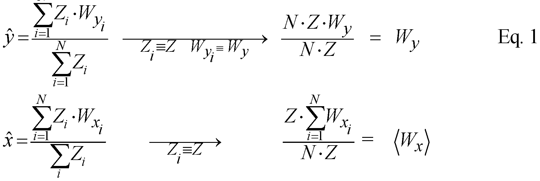
- the imaging field of view is defined as the region of image space occupied by gamma rays interacting in the crystal.
- Z is the energy signal (centroid-weight) of the i photomultiplier tube and W x and Wy are the effective photomultiplier tube locations.
- the effective locations for edge photomultiplier tube are significantly larger than their geometric values.
- ⁇ is the number of photomultiplier tube with injected events (for example, 4 in the Figure 2, which is discussed in detail below).
- the y-location of pulsed events therefore, should be equal to the y-weight value of the top photomultiplier tube row, which causes it to be located outside the imaged field of view of normal events.
- the x-location is equal to the average of the x- weight values. This is depicted in the Figure 2 below.
- the Figure 2 is an exemplary schematic depiction of an array of photomultiplier tubes with the location of the pulser peak shown with respect to an array of photomultiplier tubes into whose respective data streams identical analog pulses have been injected as shown in the Figure 1.
- the exemplary gamma camera has several photomultiplier tubes placed in a two dimensional array, with the signals from the different photomultiplier tubes being combined to provide an indication of the positions and energies of detected gamma rays.
- 4 identical pulses are injected into the data streams of the 4 top photomultiplier tubes. The identical pulses are then processed to generate a pulser peak.
- the pulser peak having the aforementioned x and y coordinates is located outside the imaging field of view of normal events.
- the total effective energy of the pulser peak can be increased by injecting additional identical analog pulses into the data streams of additional photomultiplier tubes shown in the photomultiplier tube array of the Figure 2.
- analog pulses are injected into the photomultiplier data stream using the analog pulser 106 (see Figure 1 ) at a predetermined rate as detailed above.
- the injected pulses are introduced at a rate such that they do not interfere with the normal acquired data.
- the rate of the injected pulses is low enough not to add appreciably to the deadtime, but high enough that the Poisson statistics of the number of injected events actually counted in the image is small (approximately 1 to 2% ).
- the analog pulsed events are introduced at a position and at an energy that makes them isolatable from normal data acquisition crystal events.
- the analog pulser peak is generally of the same shape as the crystal pulse so that pulse unpiling can function normally. It is to be noted that if the detector can perform unpiling, the pulser peak is of exactly the same shape as the crystal pulse. For detectors that do not perform unpiling, this restriction may be more relaxed.
- peaks in the pulsed and the normal crystal events it is desirable for peaks in the pulsed and the normal crystal events to be spatially and energetically distinguishable from one another.
- the pulser peak it is desirable for the pulser peak to be in a low count region in both the image and the energy spectrum and for the pulser to be capable of injecting pulses whose energy can be varied depending upon the isotope being used in a particular scan.
- the analog to digital converter 1 10 digitizes the data, and the integrator 1 12 integrates the pulse segments received from the analog to digital converter 1 10.
- the computer 1 14 then unpiles those pulses whose pulse shapes overlap in time.
- the spatial (x, y) and energy (E) data is passed to the acquisition computer and an image is formed. It calculates the number of injected pulses that pass through to the image using one or more windows, preferably two or more windows and more preferably at least 3 windows.
- the windows can be spatial windows - an x-window for spatial identification of the injected pulse along the x- coordinate, a y-window for spatial identification and an energy E window for an energetic identification of the injected pulse.
- the computer can calculate the amount of dead time of count loss.
- the count loss is calculated as shown in the Equation (2) below.
- the count loss or dead time of the gamma camera head 200 may then be corrected based on the value obtained from the Equation (2).
- the pulses may be introduced in an analog format as shown in the Figure 1 , or may be injected digitally after data acquired from the scintillation crystal is digitized.
- the digital injection is advantageous because it is not adversely affected by temperature fluctuations that may affect the instrumentation used in data acquisition (e.g., the pre-amplifier or the analog to digital converter).
- a digital pulse is introduced during the summation phase of the process, i.e., it is generally introduced after the data obtained from the crystal is digitized.
- the digital pulse is generally introduced at either the integrator or further downstream of the integrator after digitization of the original data obtained from the crystal is digitized.
- the Figure 3 is a schematic diagram that shows the digital injection of a pulse into the data stream at the integrator 1 12.
- the system 100 of the Figure 3 is similar to the system 100 of the Figure 1 except that it has a digital pulser 107 instead of the analog pulser 106. While the system 100 of the Figure 3 depicts the digital pulser 107 and the system 100 of the Figure 1 depicts the analog pulser, it is possible for a system to have both a digital pulser as well as an analog pulser and to use both either simultaneously or sequentially.
- a digital pulse is injected via a digital pulser 107 directly into the integrator 1 12 that lies downstream of the analog to digital converter 1 10.
- the injected digital pulse has the same characteristics of the injected analog pulse detailed above - i.e., the injected pulse is of a shape that is identical to a normal gamma event pulse and is introduced at a controllable rate (and is of a selected amplitude) to place it in a region of low counts in the spectrum of an isotope of interest, and so on. All of these characteristics and the detection of the peak using spatial and/or energy windows will not be repeated here again in the interest of brevity.
- the digitally injected pulses can be scaled to be within the energy window of the isotope(s) being imaged, or alternatively, can be scaled to be outside of the energy windows of the isotope(s) being imaged.
- These digitally injected pulses can be either within or outside of the imaging field of view. All possible combinations of the energy windows with the imaging field of view are contemplated herein.
- scaling the digital gamma-event injection pulses can be conducted to place the injected pulse within the energy window of the isotope being imaged but outside the imaging field of view.
- the scaling of the digital gamma-event injection pulses can be conducted to place the digital pulse outside of the energy window(s) of the isotopes being imaged and outside the imaging field of view.
- scaling the digital gamma-event injection pulse can be conducted to place the digital pulse within the energy window(s) of the isotopes being imaged and outside the imaging field of view of the photomultiplier tubes.
- the scaling of the digital gamma-event injection pulse can be conducted to place the digital pulse outside of the energy window(s) of the isotopes being imaged and inside the imaging field of view.
- top may be used herein to describe one element's relationship to another elements as illustrated in the Figures. It will be understood that relative terms are intended to encompass different orientations of the device in addition to the orientation depicted in the Figures. For example, if the device in one of the figures is turned over, elements described as being on the “lower” side of other elements would then be oriented on “upper” sides of the other elements. The exemplary term “lower,” can therefore, encompasses both an orientation of “lower” and “upper,” depending on the particular orientation of the figure. Similarly, if the device in one of the figures is turned over, elements described as “below” or “beneath” other elements would then be oriented “above” the other elements. The exemplary terms “below” or “beneath” can, therefore, encompass both an orientation of above and below.
- Exemplary embodiments are described herein with reference to cross section illustrations that are schematic illustrations of idealized embodiments. As such, variations from the shapes of the illustrations as a result, for example, of manufacturing techniques and/or tolerances, are to be expected. Thus, embodiments described herein should not be construed as limited to the particular shapes of regions as illustrated herein but are to include deviations in shapes that result, for example, from manufacturing. For example, a region illustrated or described as flat may, typically, have rough and/or nonlinear features. Moreover, sharp angles that are illustrated may be rounded. Thus, the regions illustrated in the figures are schematic in nature and their shapes are not intended to illustrate the precise shape of a region and are not intended to limit the scope of the present claims.
- any of the functions and steps provided in this disclosure may be implemented in hardware, software or a combination of both and may reside on one or more processing devices located at any location of a network linking the elements the disclosed system or another linked network, including the internet.
- the term “and/or” is used herein to mean both “and” as well as “or”.
- a and/or B is construed to mean A, B, or A and B.
Landscapes
- Physics & Mathematics (AREA)
- Health & Medical Sciences (AREA)
- Life Sciences & Earth Sciences (AREA)
- General Physics & Mathematics (AREA)
- High Energy & Nuclear Physics (AREA)
- Molecular Biology (AREA)
- Spectroscopy & Molecular Physics (AREA)
- Nuclear Medicine (AREA)
- Measurement Of Radiation (AREA)
- Studio Devices (AREA)
- Measuring Volume Flow (AREA)
Abstract
Description
Claims

Priority Applications (4)
| Application Number | Priority Date | Filing Date | Title |
|---|---|---|---|
| US15/316,141 US10330797B2 (en) | 2014-06-23 | 2015-06-23 | Method for dead time determination in a gamma camera and a system for accomplishing the same |
| DE112015002941.9T DE112015002941B4 (en) | 2014-06-23 | 2015-06-23 | Method for determining dead time in a gamma camera and system for achieving the same |
| HUP1700022A HU231352B1 (en) | 2014-06-23 | 2015-06-23 | Method for dead time determination in a gamma camera and a system for accomplishing the same |
| CN201580033743.1A CN106574977B (en) | 2014-06-23 | 2015-06-23 | Method for dead time determination in a gamma camera and system for implementing the method |
Applications Claiming Priority (4)
| Application Number | Priority Date | Filing Date | Title |
|---|---|---|---|
| US201462015567P | 2014-06-23 | 2014-06-23 | |
| US62/015,567 | 2014-06-23 | ||
| US201562130677P | 2015-03-10 | 2015-03-10 | |
| US62/130,677 | 2015-03-10 |
Publications (2)
| Publication Number | Publication Date |
|---|---|
| WO2015198207A1 true WO2015198207A1 (en) | 2015-12-30 |
| WO2015198207A8 WO2015198207A8 (en) | 2016-11-24 |
Family
ID=53682751
Family Applications (1)
| Application Number | Title | Priority Date | Filing Date |
|---|---|---|---|
| PCT/IB2015/054677 Ceased WO2015198207A1 (en) | 2014-06-23 | 2015-06-23 | Method for dead time determination in a gamma camera and a system for accomplishing the same |
Country Status (5)
| Country | Link |
|---|---|
| US (1) | US10330797B2 (en) |
| CN (1) | CN106574977B (en) |
| DE (1) | DE112015002941B4 (en) |
| HU (1) | HU231352B1 (en) |
| WO (1) | WO2015198207A1 (en) |
Citations (4)
| Publication number | Priority date | Publication date | Assignee | Title |
|---|---|---|---|---|
| US4058728A (en) * | 1976-05-27 | 1977-11-15 | Wisconsin Alumni Research Foundation | Correction of data loss in gamma ray scintillation cameras |
| US4369495A (en) * | 1980-06-19 | 1983-01-18 | Elscint Ltd. | Method of and means for compensating for the dead time of a gamma camera |
| US4968889A (en) * | 1989-02-01 | 1990-11-06 | The United States Of America As Represented By The United States Department Of Energy | Pulser injection with subsequent removal for gamma-ray spectrometry |
| US20110144945A1 (en) * | 2009-12-14 | 2011-06-16 | Mitsubishi Electric Corporation | Radiation measuring device and diagnostic method thereof |
Family Cites Families (3)
| Publication number | Priority date | Publication date | Assignee | Title |
|---|---|---|---|---|
| CN100458383C (en) * | 2005-11-23 | 2009-02-04 | 中国科学院物理研究所 | Method for collecting snowslide signal of APD single photon detector |
| US20100193700A1 (en) * | 2007-06-01 | 2010-08-05 | Koninklijke Philips Electronics N.V. | Spectral photon counting detector |
| CN102644009B (en) * | 2008-02-12 | 2015-04-01 | 株式会社神户制钢所 | Aluminum-alloy multi-layered sheet |
-
2015
- 2015-06-23 US US15/316,141 patent/US10330797B2/en active Active
- 2015-06-23 HU HUP1700022A patent/HU231352B1/en unknown
- 2015-06-23 DE DE112015002941.9T patent/DE112015002941B4/en active Active
- 2015-06-23 WO PCT/IB2015/054677 patent/WO2015198207A1/en not_active Ceased
- 2015-06-23 CN CN201580033743.1A patent/CN106574977B/en active Active
Patent Citations (4)
| Publication number | Priority date | Publication date | Assignee | Title |
|---|---|---|---|---|
| US4058728A (en) * | 1976-05-27 | 1977-11-15 | Wisconsin Alumni Research Foundation | Correction of data loss in gamma ray scintillation cameras |
| US4369495A (en) * | 1980-06-19 | 1983-01-18 | Elscint Ltd. | Method of and means for compensating for the dead time of a gamma camera |
| US4968889A (en) * | 1989-02-01 | 1990-11-06 | The United States Of America As Represented By The United States Department Of Energy | Pulser injection with subsequent removal for gamma-ray spectrometry |
| US20110144945A1 (en) * | 2009-12-14 | 2011-06-16 | Mitsubishi Electric Corporation | Radiation measuring device and diagnostic method thereof |
Non-Patent Citations (1)
| Title |
|---|
| CARDOSO J M ET AL: "Optimization of digital spectrometers using a pulse streaming generator", 2004 IEEE NUCLEAR SCIENCE SYMPOSIUM CONFERENCE RECORD 16-22 OCT. 2004 ROME, ITALY, IEEE, PISCATAWAY, NJ, USA, vol. 3, 16 October 2004 (2004-10-16), pages 1391 - 1395, XP010819025, ISBN: 978-0-7803-8700-3, DOI: 10.1109/NSSMIC.2004.1462500 * |
Also Published As
| Publication number | Publication date |
|---|---|
| DE112015002941T5 (en) | 2017-03-16 |
| CN106574977B (en) | 2019-09-17 |
| WO2015198207A8 (en) | 2016-11-24 |
| HUP1700022A2 (en) | 2017-05-29 |
| US10330797B2 (en) | 2019-06-25 |
| CN106574977A8 (en) | 2017-07-07 |
| CN106574977A (en) | 2017-04-19 |
| HU231352B1 (en) | 2023-01-28 |
| US20170115404A1 (en) | 2017-04-27 |
| DE112015002941T8 (en) | 2017-05-11 |
| DE112015002941B4 (en) | 2025-12-04 |
Similar Documents
| Publication | Publication Date | Title |
|---|---|---|
| AU2009230876B2 (en) | Radiation imaging method with individual signal resolution | |
| JP4160275B2 (en) | Energy measuring method and measuring device | |
| US10061043B2 (en) | Apparatus and method for the evaluation of gamma radiation events | |
| US8294110B2 (en) | Method for improved correction of SiPM non-linearity in multiplexed radiation detectors | |
| DE69816626T2 (en) | METHOD AND DEVICE FOR PREVENTING 'PILE-UP' WHEN DETECTING ARRIVING ENERGY SIGNALS | |
| EP2867701B1 (en) | Digital positron emission tomography (dpet) energy calibration method | |
| CN107110983A (en) | Coincidence correction based on pixel | |
| JP7317586B2 (en) | MEDICAL IMAGE PROCESSING APPARATUS, METHOD AND PROGRAM | |
| CN102670232B (en) | Positron emission computed tomography device, and method executed through the same | |
| US11543545B2 (en) | Method and apparatus to use a broad-spectrum energy source to correct a nonlinear energy response of a gamma-ray detector | |
| KR102063828B1 (en) | Signal detection method of radiographic imaging device and radiographic imaging device | |
| US20260003084A1 (en) | Method and apparatus for processing scintillation pulses, and device and storage medium | |
| US10330797B2 (en) | Method for dead time determination in a gamma camera and a system for accomplishing the same | |
| Niu et al. | Evaluation of energy correction algorithm for signals of PET in heavy-ion cancer therapy device | |
| US10353081B2 (en) | Gamma system count loss correction with virtual pulse injection | |
| Schmand et al. | A pulse shape restore method for event localization in PET scintillation detection | |
| HK1154659A (en) | Radiation imaging method with individual signal resolution | |
| JPS6239944B2 (en) |
Legal Events
| Date | Code | Title | Description |
|---|---|---|---|
| 121 | Ep: the epo has been informed by wipo that ep was designated in this application |
Ref document number: 15739336 Country of ref document: EP Kind code of ref document: A1 |
|
| WWE | Wipo information: entry into national phase |
Ref document number: 15316141 Country of ref document: US |
|
| WWE | Wipo information: entry into national phase |
Ref document number: 112015002941 Country of ref document: DE |
|
| 122 | Ep: pct application non-entry in european phase |
Ref document number: 15739336 Country of ref document: EP Kind code of ref document: A1 |
|
| WWG | Wipo information: grant in national office |
Ref document number: 112015002941 Country of ref document: DE |