WO2015190124A1 - モーフィング翼 - Google Patents
モーフィング翼 Download PDFInfo
- Publication number
- WO2015190124A1 WO2015190124A1 PCT/JP2015/053078 JP2015053078W WO2015190124A1 WO 2015190124 A1 WO2015190124 A1 WO 2015190124A1 JP 2015053078 W JP2015053078 W JP 2015053078W WO 2015190124 A1 WO2015190124 A1 WO 2015190124A1
- Authority
- WO
- WIPO (PCT)
- Prior art keywords
- blade
- wing
- morphing
- elements
- blade elements
- Prior art date
- Legal status (The legal status is an assumption and is not a legal conclusion. Google has not performed a legal analysis and makes no representation as to the accuracy of the status listed.)
- Ceased
Links
Images





Classifications
-
- B—PERFORMING OPERATIONS; TRANSPORTING
- B64—AIRCRAFT; AVIATION; COSMONAUTICS
- B64C—AEROPLANES; HELICOPTERS
- B64C3/00—Wings
- B64C3/38—Adjustment of complete wings or parts thereof
- B64C3/44—Varying camber
- B64C3/48—Varying camber by relatively-movable parts of wing structures
-
- B—PERFORMING OPERATIONS; TRANSPORTING
- B64—AIRCRAFT; AVIATION; COSMONAUTICS
- B64C—AEROPLANES; HELICOPTERS
- B64C9/00—Adjustable control surfaces or members, e.g. rudders
- B64C9/14—Adjustable control surfaces or members, e.g. rudders forming slots
Definitions
- the airfoil for generating lift in the fluid is not a fixed wing that is usually used, but is divided into a plurality of blade elements in the chord direction in whole or in part, and is formed into a cascade. Equipped with a drive mechanism that changes the relative positional relationship of the blade elements, and with timely control, morphing blades that can freely change lift / drag, rolling moment, etc.
- the present invention relates to a morphing wing applied to wing deformation such as a large hard wing.
- an aircraft airfoil is designed to generate lift efficiently with minimal drag in a uniform flow, and it is desirable if the wing attitude angle (attack angle) with respect to the flow is within a certain range. Properties are guaranteed.
- the angle of attack deviates from that range, flow separation begins, the lift rapidly decreases, and at the same time the drag increases rapidly.
- flight control becomes extremely difficult, and abnormal postures such as drilling are entered, In some cases, it becomes unrecoverable.
- many morphing wings that change the airfoil have been proposed particularly in the aircraft field (see, for example, Non-Patent Documents 1 and 2). It gives the wings freedom of deformation (twisting, warping, changes in planar shape, etc.), and in principle meets a variety of flight conditions and mission requirements.
- a leading edge slat and a trailing edge flap are added to increase the wing area and camber ratio.
- slats and flaps slot presence / absence, number of flaps, etc.
- driving methods see, for example, Non-Patent Document 3.
- a method of delaying separation by supplying kinetic energy to the blade surface actively or passively has been proposed.
- Non-Patent Documents 1 and 2 Various concepts for realizing morphing wings as described in Non-Patent Documents 1 and 2 have been proposed, but the deformation structure and weight increase due to additional actuators offset the advantage of blade deformation. For this reason, the above problems cannot be solved sufficiently, and there are very few examples that have been put to practical use.
- the wing provided with the slat and the flap as described in Non-Patent Document 3 has an effect of increasing the wing area and an effect of increasing the camber ratio, the above problems are sufficiently compared with the wing deformation like the morphing wing described above. The advantage to solve is small.
- a blade that supplies kinetic energy to the blade surface as described in Non-Patent Document 4 is effective in improving aerodynamic characteristics, but it is necessary to add a disturbance, a vortex generator, etc.
- the improvement of the aerodynamic characteristics by this alone has not sufficiently solved the above problem.
- the present invention solves the above-described problems, and can greatly deform the entire shape of the region of the blade array with a light and simple mechanism without complicating and increasing the size of the structure.
- Excellent increase effect and camber ratio increase effect especially when applied to small and light aircraft, it is difficult to stall even when encountering turbulence, landing at low speed and high angle of attack with a deep approach angle is possible, dramatically improving safety
- An object of the present invention is to provide a morphing wing capable of performing the above.
- a morphing wing includes a drive mechanism in which the entire wing or a partial region is divided into a plurality of blade elements in a chord direction to form a cascade, and the relative positional relationship of the plurality of blade elements is changed.
- a morphing wing whose shape of the entire bladed region is changed, wherein the plurality of blade elements are arranged at one central blade element and at least one front blade element at the front and rear of the central blade element.
- the drive mechanism is configured to change the relative position of the adjacent blade elements.
- the plurality of wing elements include one central wing element and one or more movable wing elements arranged in front and rear of the central wing element, respectively, and a driving mechanism
- the plurality of wing elements include one central wing element and one or more movable wing elements arranged in front and rear of the central wing element, respectively, and a driving mechanism
- all the blade elements including the central blade element can be configured to be small, and it is possible to obtain a light and simple mechanism without making the structure complicated and large.
- each of the divided blade elements has a low Reynolds number blade that cannot generate sufficient lift as a single blade element (for example, a blade in which the chord length of each blade element is closed).
- the maximum length is 50% or less with respect to the length of the entire string, it is possible to generate a higher lift than the fixed wing as an aggregate of low Reynolds number blade elements.
- the plurality of blade elements are configured such that slots are formed between adjacent blade elements. Can be supplied to the upper surface of the blade to delay the separation, and aerodynamic characteristics can be improved without adding other disturbances or adding a vortex generator.
- the drive mechanism is configured to be able to change the angle of attack of each of the plurality of blade elements, the shape of the entire blade can be further greatly changed, and the camber ratio The increase effect can be increased.
- the drive mechanism includes a base member fixed to the central blade element, an arm member fixed to the movable blade element and movably connected to the base member, and a plurality of arm members
- the link member that links the movements of the blades allows the movement of the chord direction of multiple blade elements and the change in the angle of attack to be linked, so that the deformation of the entire blade can be controlled by a single actuator.
- a light and simple mechanism can be achieved without making the structure complicated and large.
- the modification explanatory view of the morphing wings concerning one embodiment of the present invention Explanatory drawing of the flow of the 60 degree form and 30 degree form of the morphing wing
- the morphing wing of the present invention includes a drive mechanism in which the entire wing or a partial region is divided into a plurality of blade elements in the chord direction to form a cascade, and the relative positional relationship of the plurality of blade elements is changed.
- a morphing wing in which the shape of the entire arrayed region is changed, and a plurality of wing elements are arranged with one central wing element and at least one movable wing element in front and behind the central wing element.
- the drive mechanism is configured to be able to change the relative position of adjacent blade elements, and the entire blade can be greatly deformed with a light and simple mechanism without complicating or increasing the size of the structure. Any specific embodiment may be used as long as the blade area increasing effect and the camber ratio increasing effect are excellent.
- the cascade is composed of five blade elements in which the movable blade elements 112a and 112b are arranged on the front side of the central blade element 111 and the movable blade elements 112c and 112d are arranged on the rear side, and the camber ratio is 4% to 24%.
- FIG. 1 shows a morphing blade whose movable blade element 112d at the rearmost part can be deformed from 0 ° to 60 °.
- the cruise mode is equivalent to an integral fixed wing, and a slot S is formed between adjacent wing elements by deformation. At the time of deformation, as shown in FIGS.
- the kinetic energy of the lower surface of the blade is supplied to the upper surface of the blade to hold the turbulent boundary layer, and the separation delay effect is obtained. Reduction of the lift force can be suppressed.
- the drag becomes larger than that of the fixed blade.
- the changes in lift and drag with respect to the angle of attack are smooth, there is no sudden decrease in lift and drag immediately after peeling, and smooth lift-drag ratio control is possible by adjusting the slot opening / closing degree according to the flow.
- CL indicates lift
- CD indicates drag
- 1 and 4 are graphs of fixed wings (substantially the same as the cruise mode of the present invention)
- 2 and 5 are graphs of fixed wings with a camber ratio of 24%
- 3 and 6 is a graph in which the horizontal axis represents the angle of attack when the morphing wing of an example of the present invention is transformed into a 60 ° form.
- the mechanism of the morphing wing 100 is shown in FIGS.
- the morphing blade 100 is divided into a plurality of blade elements in the chord direction by dividing the entire blade into a plurality of blade elements.
- the movable blade elements 112a and 112b are disposed on the front side of the central blade element 111, and the movable blade elements 112c are disposed on the rear side.
- the driving mechanism 120 is composed of five blade elements with 112d disposed therein, and changes the relative positional relationship and posture of the movable blade elements 112a to 112d with respect to the central blade element 111.
- the drive mechanism 120 includes a base member 121 fixed to the central blade element 111, arm members 122a to d fixed to the movable blade elements 112a to 112d and rotatably connected to the base member 121, and Link members 123a to 123d for interlocking the rotation of the arm members 122a to 122d are provided.
- the link member 123s is provided so as to be rotatable about the rotation center C with respect to the base member 121.
- the link members 123a to 123d rotate at one end to the respective arm members 122a to d and the other end to the link member 123s. It is linked movably.
- each arm member 122a-d is connected via each link member 123a-d.
- each link member 123a to d, s and each arm member 122a to d since all members are interlocked by rotating at least one rotation connecting portion (indicated by a black dot in FIG. 5) of each link member 123a to d, s and each arm member 122a to d, the actuator Any member may be driven at any position. In consideration of driving force, a plurality of actuators may be provided. Furthermore, by changing the length of each link member 123a to d, s, the length of each arm member 122a to d, and the position of the rotary connecting portion, the position and posture of each movable blade 112a to 112d can be changed arbitrarily. The entire wing can be deformed into an arbitrary shape. In the above embodiment, the number of movable blade elements 112 is four.
- any number of movable blade elements may be used, and some movable blade elements are driven independently without being linked to the link member, and the position or position of each movable blade element is individually determined.
- the angle of attack may be controllable.
- the movable blade element may be driven by a motion mechanism other than the base member, the arm member, and the link member, for example, a motion mechanism using a cam and a cam follower, a gear, a chain, or the like, or by appropriately combining them.
- the drive mechanism 120 may be provided at any position in the width direction of the blade, and a plurality of drive mechanisms 120 may be provided in the width direction.
- a plurality of drive mechanisms 120 may be provided in the width direction.
- the central blade element and the movable blade element may have different shapes in the width direction, and when a drive mechanism is provided at both ends, the operation at the time of deformation may be defined to be different at both ends.
- the rear end of the upper surface side of the central wing element and the movable wing element is extended rearward, or the upper surface of the morphing wing is made of an elastically deformable membrane. You may comprise so that it may cover.
- the central blade element has a hollow structure, or the movable blade elements 112a to 112d have a hollow structure as shown in the reference photos shown in FIGS. 6 and 7, and these have a honeycomb structure, an uneven structure, etc. It is also possible to reduce the weight while ensuring rigidity. Further, each member such as a base member, an arm member, and a link member can also be reduced in weight while ensuring strength and rigidity by adopting a hollow structure, a honeycomb structure, an uneven structure, or the like. Furthermore, passive deformation of the morphing wing according to the external force may be allowed by configuring part or all of the arm member, the link member, etc. with a material that can be elastically deformed.
- the entire wing can be greatly deformed with a light and simple mechanism without complicating and increasing the size of the structure, and the wing area increasing effect and camber ratio increasing effect Can be improved.
- the morphing wing of the present invention is particularly effective in improving turbulence resistance performance for aircraft and realizing high angle of attack and high descent landing (Semi-VTOL function), thereby improving aviation safety by reducing the probability of aircraft loss
- SAtOL function high angle of attack and high descent landing
- There are significant effects such as expanding the use of small aircraft and expanding the use of unmanned aircraft.
- it can be applied as a blade for various purposes such as improving the power generation efficiency of a vertical axis wind turbine and improving the propulsion efficiency by applying it to a ship-mounted hard blade sail.
Landscapes
- Engineering & Computer Science (AREA)
- Aviation & Aerospace Engineering (AREA)
- Mechanical Engineering (AREA)
- Structures Of Non-Positive Displacement Pumps (AREA)
Abstract
構造を複雑化、大型化することなく、軽量で単純な機構で翼全体を大きく変形することができ、翼面積増大効果やキャンバ比増効果に優れたモーフィング翼を提供すること。 翼100が翼弦方向の複数の翼素に分割して翼列化され、複数の翼素の相対位置を変更する駆動機構120を備えたモーフィング翼であって、複数の翼素が、1枚の中央翼素111と前方及び後方にそれぞれ1枚以上配置された可動翼素112とを有し、駆動機構120が、隣接する翼素の相対位置を変更可能とするように構成されていること。
Description
本発明は、流体中で揚力を発生させるための翼型を、通常用いられる固定翼ではなく、全体又は一部領域が翼弦方向の複数の翼素に分割して翼列化され、複数の翼素の相対的な位置関係を変更する駆動機構を備え、適時制御することにより、揚力/抗力・ローリングモーメントなどを自在に変化させるモーフィング翼に関し、航空機用をはじめ、垂直軸風車、船舶搭載型大型硬翼などの翼変形などに適用されるモーフィング翼に関する。
一般的に、航空機の翼型は、一様流中で最小抗力で効率よく揚力を発生するよう設計されており、流れに対する翼姿勢角(迎角)が一定範囲内に収まっていれば望ましい空力特性が保証される。
しかしながら、迎角がその範囲を逸脱すると流れの剥離が始まり、急速に揚力が低下、同時に抗力が急増し、この空力特性劣化に伴い、飛行制御は著しく困難となり、きりもみなど異常姿勢に入り、場合によっては回復不能となる。
そこで、翼形を変化させるモーフィング翼に関して、特に航空機分野において数多く提案されてきた(例えば、非特許文献1、2等参照。)。
翼に変形自由度(ねじり、反り、平面形状の変化など)を与え、原理的に多様な飛行条件とミッション要求に対応するものである。
しかしながら、迎角がその範囲を逸脱すると流れの剥離が始まり、急速に揚力が低下、同時に抗力が急増し、この空力特性劣化に伴い、飛行制御は著しく困難となり、きりもみなど異常姿勢に入り、場合によっては回復不能となる。
そこで、翼形を変化させるモーフィング翼に関して、特に航空機分野において数多く提案されてきた(例えば、非特許文献1、2等参照。)。
翼に変形自由度(ねじり、反り、平面形状の変化など)を与え、原理的に多様な飛行条件とミッション要求に対応するものである。
また、航空機の低速時の揚力増大のために、中央母翼(揚力発生の主領域)に加えて、前縁スラット、後縁フラップを追加し、翼面積増大効果、キャンバ比増効果を狙う方法が公知である。
これらのものでは、スラットとフラップの形態(スロット有無、フラップ枚数など)、駆動方式は多岐にわたる(例えば、非特許文献3等参照。)。
また、翼表面へアクティブあるいはパッシブに運動エネルギーを供給することにより剥離を遅らせる方法が提案されている。
特に、主翼後縁のフラップの上面あるいは下面からの高圧ジェット噴射、翼表面強制振動など擾乱付加、渦発生装置取り付け、最近ではこれら機能のマイクロアクチュエータによる実現法が提案されている(例えば、非特許文献4等参照。)。
これらのものでは、スラットとフラップの形態(スロット有無、フラップ枚数など)、駆動方式は多岐にわたる(例えば、非特許文献3等参照。)。
また、翼表面へアクティブあるいはパッシブに運動エネルギーを供給することにより剥離を遅らせる方法が提案されている。
特に、主翼後縁のフラップの上面あるいは下面からの高圧ジェット噴射、翼表面強制振動など擾乱付加、渦発生装置取り付け、最近ではこれら機能のマイクロアクチュエータによる実現法が提案されている(例えば、非特許文献4等参照。)。
玉山、モーフィングに関する動向、ながれ 28 pp.277-284 (2009)
Barbarino et al., "A Review of Morphing Aircraft", Journal of Material Systems and Structures, Vol. 22 June (2011)
最適化技術を応用した高揚力装置の設計技術開発、革新航空機技術に関する調査研究:成果報告書 No.2215
マイクロアクチュエータを用いた乱流制御、剥離制御技術の研究、革新航空機技術に関する調査研究:成果報告書 No.1103
一般的な航空機は翼形態が固定されているために、乱気流遭遇により容易に失速に陥り、特に離着陸時の低速領域では復航が不可能となり、特に小型軽量の低翼面荷重低速機において顕著である。
例えば、航空機が悪天候下や山間部、あるいは離着陸時の乱気流に遭遇した時の安全性は喫緊に解決すべき課題と広く認識されているが、特に小型軽量飛行機は、エアラインが運航する大型旅客機に比べて、翼面荷重が一桁小さいため耐乱気流性能が著しく不足しており、より安全性の向上が求められている。
通常、固定翼航空機の着陸においては、フラップなどの高揚力デバイスを用いても経路角3~5°のアプローチとなるため、滑走路周辺は障害物のない十分広い空域が必要になる。
例えば、航空機が悪天候下や山間部、あるいは離着陸時の乱気流に遭遇した時の安全性は喫緊に解決すべき課題と広く認識されているが、特に小型軽量飛行機は、エアラインが運航する大型旅客機に比べて、翼面荷重が一桁小さいため耐乱気流性能が著しく不足しており、より安全性の向上が求められている。
通常、固定翼航空機の着陸においては、フラップなどの高揚力デバイスを用いても経路角3~5°のアプローチとなるため、滑走路周辺は障害物のない十分広い空域が必要になる。
また、風向風速によっては横風制限により滑走路方向への安全なアプローチが困難な場合もあり、さらに、エンジン停止など緊急時を想定した場合も含め、滑走路以外に着陸可能エリアがないことは、搭乗者、機体の安全のみならず、対地安全の観点からも問題がある。
日本のように国土が狭くその70%を山間部が占める地理的環境においては、小型軽量飛行機の市場は非常に小さいため、周辺に障害物のない航空機専用離発着場を数多く整備・維持することはコスト的に成立しない。
逆に、小型軽量飛行機用インフラが整備されないことが小型軽量飛行機の産業活性化、無人機利用拡大の阻害要因となっている。
これらの課題は、前述したような公知のモーフィング翼、スラットとフラップを備えた翼、翼表面への運動エネルギーを供給する翼等を適用しても、充分に解決できるものではない。
日本のように国土が狭くその70%を山間部が占める地理的環境においては、小型軽量飛行機の市場は非常に小さいため、周辺に障害物のない航空機専用離発着場を数多く整備・維持することはコスト的に成立しない。
逆に、小型軽量飛行機用インフラが整備されないことが小型軽量飛行機の産業活性化、無人機利用拡大の阻害要因となっている。
これらの課題は、前述したような公知のモーフィング翼、スラットとフラップを備えた翼、翼表面への運動エネルギーを供給する翼等を適用しても、充分に解決できるものではない。
非特許文献1、2に記載されたようなモーフィング翼は、実現のためのさまざまなコンセプトが提案されてきたが、変形構造や、追加アクチュエータによる重量増が、翼変形によるアドバンテージを相殺してしまうため、上記課題を充分に解決することができず、実用化に至った例は極めて少ない。
非特許文献3に記載されたようなスラットとフラップを備えた翼は、翼面積増大効果、キャンバ比増効果はあるものの、上述のモーフィング翼のような翼変形に比べると、上記課題を充分に解決するためのアドバンテージは小さい。
非特許文献4に記載されたような翼表面への運動エネルギーを供給する翼は、空力特性の向上には効果はあるが、そのための擾乱付加、渦発生装置等を追加する必要があり、また、このことによる空力特性の向上のみでは、やはり、上記課題を充分に解決することができなかった。
非特許文献3に記載されたようなスラットとフラップを備えた翼は、翼面積増大効果、キャンバ比増効果はあるものの、上述のモーフィング翼のような翼変形に比べると、上記課題を充分に解決するためのアドバンテージは小さい。
非特許文献4に記載されたような翼表面への運動エネルギーを供給する翼は、空力特性の向上には効果はあるが、そのための擾乱付加、渦発生装置等を追加する必要があり、また、このことによる空力特性の向上のみでは、やはり、上記課題を充分に解決することができなかった。
そこで、本発明は前述した課題を解決するものであり、構造を複雑化、大型化することなく、軽量で単純な機構で翼列化された領域全体形状を大きく変形することができ、翼面積増大効果やキャンバ比増効果に優れ、特に、小型軽量飛行機に適用した際に、乱気流遭遇時でも失速しにくく、アプローチ角度の深い低速高迎角着陸が可能で、安全性を飛躍的に向上することが可能なモーフィング翼を提供することを目的とする。
本発明に係るモーフィング翼は、翼全体又は一部領域が翼弦方向の複数の翼素に分割して翼列化され、前記複数の翼素の相対的な位置関係を変更する駆動機構を備え、翼列化された領域全体の形状が変更されるモーフィング翼であって、前記複数の翼素が、1枚の中央翼素と、前記中央翼素の前方及び後方にそれぞれ1枚以上配置された可動翼素とを有し、前記駆動機構が、隣接する前記翼素の相対位置を変更可能とするように構成されていることにより、前記課題を解決するものである。
請求項1に係るモーフィング翼によれば、複数の翼素が、1枚の中央翼素と、中央翼素の前方及び後方にそれぞれ1枚以上配置された可動翼素とを有し、駆動機構が、隣接する翼素の相対位置を変更可能とし、翼列化された領域全体の形状を大きく変形可能とすることで、翼面積増大効果やキャンバ比増効果を奏することができる。
また、中央翼素を含み、全ての翼素を、小さく構成することができ、構造を複雑化、大型化することなく、軽量で単純な機構とすることが可能となる。
さらに、分割された各翼素は、いずれも単翼素としては十分な揚力を発生することができない低レイノルズ数翼(例えば、各翼素の翼弦方向の長さが、閉じた状態の翼弦全体の長さに対して、最大のものでも50%以下)でありながら、翼全体を低レイノルズ数翼素の集合体として固定翼よりも大きな揚力を発生させることが可能となる。
また、中央翼素を含み、全ての翼素を、小さく構成することができ、構造を複雑化、大型化することなく、軽量で単純な機構とすることが可能となる。
さらに、分割された各翼素は、いずれも単翼素としては十分な揚力を発生することができない低レイノルズ数翼(例えば、各翼素の翼弦方向の長さが、閉じた状態の翼弦全体の長さに対して、最大のものでも50%以下)でありながら、翼全体を低レイノルズ数翼素の集合体として固定翼よりも大きな揚力を発生させることが可能となる。
本請求項2に記載の構成によれば、複数の翼素は、隣接する翼素と間にスロットが形成されるように構成されていることにより、複数の翼素の移動に応じ、翼下面の運動エネルギーを翼上面に供給して剥離を遅らせることが可能となり、他の擾乱付加、渦発生装置等を追加することなく、空力特性を向上させることができる。
本請求項3に記載の構成によれば、駆動機構が、複数の翼素の迎角をそれぞれ変更可能に構成されていることにより、さらに翼全体の形状を大きく変化させることができ、キャンバ比増効果を大きくすることが可能となる。
本請求項4に記載の構成によれば、駆動機構が、中央翼素に固定されたベース部材と、可動翼素に固定されベース部材に運動可能に連結されたアーム部材と、複数のアーム部材の運動を連動させるリンク部材とを備えていることにより、複数の翼素の翼弦方向の移動や迎角の変更を連動させることができるため、1つのアクチュエータで翼全体の変形を制御することが可能となり、構造を複雑化、大型化することなく、軽量で単純な機構とすることが可能となる。
本請求項3に記載の構成によれば、駆動機構が、複数の翼素の迎角をそれぞれ変更可能に構成されていることにより、さらに翼全体の形状を大きく変化させることができ、キャンバ比増効果を大きくすることが可能となる。
本請求項4に記載の構成によれば、駆動機構が、中央翼素に固定されたベース部材と、可動翼素に固定されベース部材に運動可能に連結されたアーム部材と、複数のアーム部材の運動を連動させるリンク部材とを備えていることにより、複数の翼素の翼弦方向の移動や迎角の変更を連動させることができるため、1つのアクチュエータで翼全体の変形を制御することが可能となり、構造を複雑化、大型化することなく、軽量で単純な機構とすることが可能となる。
100 ・・・ モーフィング翼
111 ・・・ 中央翼素
112 ・・・ 可動翼素
120 ・・・ 駆動機構
121 ・・・ ベース部材
122 ・・・ アーム部材
123 ・・・ リンク部材
C ・・・ 回転中心
S ・・・ スロット
111 ・・・ 中央翼素
112 ・・・ 可動翼素
120 ・・・ 駆動機構
121 ・・・ ベース部材
122 ・・・ アーム部材
123 ・・・ リンク部材
C ・・・ 回転中心
S ・・・ スロット
本発明のモーフィング翼は、翼全体又は一部領域が翼弦方向の複数の翼素に分割して翼列化され、複数の翼素の相対的な位置関係を変更する駆動機構を備え、翼列化された領域全体の形状が変更されるモーフィング翼であって、複数の翼素が、1枚の中央翼素と、中央翼素の前方及び後方にそれぞれ1枚以上配置された可動翼素とを有し、駆動機構が、隣接する翼素の相対位置を変更可能とするように構成され、構造を複雑化、大型化することなく、軽量で単純な機構で翼全体を大きく変形することができ、翼面積増大効果やキャンバ比増効果に優れたものであれば、その具体的な実施態様はいかなるものであっても良い。
本発明の一例として、翼列を中央翼素111の前側に可動翼素112a、112bを、後側に可動翼素112c、112dを配置した5枚の翼素からなり、キャンバ比4%~24%、最後部の可動翼素112dが0°~60°に変形可能なモーフィング翼を、図1に示す。
この例では、巡航時形態では、一体の固定翼と同等であり、変形することで隣接する翼素間にスロットSが形成される。
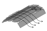
変形時には、この計4列のスロットSによって、図2、図3に示すように、翼下面の運動エネルギーが翼上面に供給されて乱流境界層を保持して剥離遅延効果が得られ、急激な揚力の低下を抑制することができる。
一方、翼下面の流れがこの4列のスロットSに流入通過する際発生する摩擦抵抗により、抗力は固定翼の場合より大きくなる。
ただし、揚力、抗力の迎角に対する変化は滑らかであり、剥離直後での揚力急減、抗力急増がなく、スロット開閉度を流れに応じて調整することにより滑らかな揚抗比制御が可能となる。
この例では、巡航時形態では、一体の固定翼と同等であり、変形することで隣接する翼素間にスロットSが形成される。
変形時には、この計4列のスロットSによって、図2、図3に示すように、翼下面の運動エネルギーが翼上面に供給されて乱流境界層を保持して剥離遅延効果が得られ、急激な揚力の低下を抑制することができる。
一方、翼下面の流れがこの4列のスロットSに流入通過する際発生する摩擦抵抗により、抗力は固定翼の場合より大きくなる。
ただし、揚力、抗力の迎角に対する変化は滑らかであり、剥離直後での揚力急減、抗力急増がなく、スロット開閉度を流れに応じて調整することにより滑らかな揚抗比制御が可能となる。
これらの特性を、図4のグラフに示す。
図中のCLは揚力、CDは抗力を示し、1及び4は固定翼(本発明の巡航時形態とほぼ同じ)のグラフ、2及び5はキャンバ比24%とした固定翼のグラフ、3及び6は本発明の一例のモーフィング翼を60°形態に変形した時の、それぞれ横軸を迎角としたグラフである。
このグラフからわかるように、本発明の一例のモーフィング翼では、翼列開度を大きくすることにより、翼面積増大効果、キャンバ比増大効果を奏し、どの迎角領域においても固定翼(図中のCL(Original)1)よりも大きな揚力を発生でき、迎角1°~45°の範囲では、キャンバ比24%とした固定翼(CL(24%CamberSingle)2)よりも大きな揚力を発生できる。
また、剥離開始迎角は、固定翼(図中のCL(Original)1)の14°から本発明の一例のモーフィング翼を60°形態に変形した時(図中のCL(Morphing60deg)3)では30°へと移行しており、航空機の場合、失速を遅らせ粘ることができる。
図中のCLは揚力、CDは抗力を示し、1及び4は固定翼(本発明の巡航時形態とほぼ同じ)のグラフ、2及び5はキャンバ比24%とした固定翼のグラフ、3及び6は本発明の一例のモーフィング翼を60°形態に変形した時の、それぞれ横軸を迎角としたグラフである。
このグラフからわかるように、本発明の一例のモーフィング翼では、翼列開度を大きくすることにより、翼面積増大効果、キャンバ比増大効果を奏し、どの迎角領域においても固定翼(図中のCL(Original)1)よりも大きな揚力を発生でき、迎角1°~45°の範囲では、キャンバ比24%とした固定翼(CL(24%CamberSingle)2)よりも大きな揚力を発生できる。
また、剥離開始迎角は、固定翼(図中のCL(Original)1)の14°から本発明の一例のモーフィング翼を60°形態に変形した時(図中のCL(Morphing60deg)3)では30°へと移行しており、航空機の場合、失速を遅らせ粘ることができる。
さらに、本発明の一例のモーフィング翼を60°形態に変形した時(図中のCL(Morphing60deg)3)は、迎角が大きくなり(>30度)剥離が始まっても揚力は急減せず、非常になだらかに減少する。
したがって、ピッチングモーメントも剥離とともに急変せず、抗力(図中のCD(Morphing60deg)6)も急増がなくゆっくりと増加することから、航空機に適用した場合、ピッチ角0°付近に維持したまま、高迎角(45°程度)での低速高降下着陸が達成できる。
例えば、試作機による実飛行において、固定翼では不可能な高迎角(20度)で、図8に示す参考写真のように、深いアプローチ角(25度)が実現されている。
したがって、ピッチングモーメントも剥離とともに急変せず、抗力(図中のCD(Morphing60deg)6)も急増がなくゆっくりと増加することから、航空機に適用した場合、ピッチ角0°付近に維持したまま、高迎角(45°程度)での低速高降下着陸が達成できる。
例えば、試作機による実飛行において、固定翼では不可能な高迎角(20度)で、図8に示す参考写真のように、深いアプローチ角(25度)が実現されている。
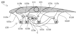
本発明の一実施形態に係るモーフィング翼100の機構を、図5乃至図7に示す。
モーフィング翼100は、翼全体を翼弦方向の複数の翼素に分割して翼列化されており、中央翼素111の前側に可動翼素112a、112bを、後側に可動翼素112c、112dを配置した5枚の翼素からなり、中央翼素111に対する各可動翼素112a~dの相対的な位置関係及び姿勢を変更する駆動機構120を備えている。
駆動機構120は、中央翼素111に固定されたベース部材121と、各可動翼素112a~dにそれぞれ固定されベース部材121に対して回動可能に連結されたアーム部材122a~dと、各アーム部材122a~dの回動を連動させるリンク部材123a~d、sとを備えている。
モーフィング翼100は、翼全体を翼弦方向の複数の翼素に分割して翼列化されており、中央翼素111の前側に可動翼素112a、112bを、後側に可動翼素112c、112dを配置した5枚の翼素からなり、中央翼素111に対する各可動翼素112a~dの相対的な位置関係及び姿勢を変更する駆動機構120を備えている。
駆動機構120は、中央翼素111に固定されたベース部材121と、各可動翼素112a~dにそれぞれ固定されベース部材121に対して回動可能に連結されたアーム部材122a~dと、各アーム部材122a~dの回動を連動させるリンク部材123a~d、sとを備えている。
リンク部材123sは、ベース部材121に対して回転中心Cを中心に回動自在に設けられ、リンク部材123a~dは、一端をそれぞれ各アーム部材122a~dに、他端をリンク部材123sに回動可能に連結されている。
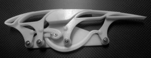
リンク部材123sが1個のアクチュエータ(図示しない)によってベース部材121に対して回動することにより、図7の参考写真に示すように、各リンク部材123a~dを介して各アーム部材122a~dをベース部材121に対して同時に回動させ、中央翼素111に対する各可動翼素112a~dの相対的な位置関係及び姿勢が変更され、モーフィング翼100が変形する。
リンク部材123sが1個のアクチュエータ(図示しない)によってベース部材121に対して回動することにより、図7の参考写真に示すように、各リンク部材123a~dを介して各アーム部材122a~dをベース部材121に対して同時に回動させ、中央翼素111に対する各可動翼素112a~dの相対的な位置関係及び姿勢が変更され、モーフィング翼100が変形する。
なお、各リンク部材123a~d、s、各アーム部材122a~dの少なくともいずれか1つの回動連結部(図5の黒点で示す)を回動すれば全ての部材が連動するため、アクチュエータは、任意の位置で任意の部材を駆動すればよい。
また、駆動力を考慮して、アクチュエータを複数設けてもよい。
さらに、各リンク部材123a~d、s、各アーム部材122a~dの長さ、回動連結部の位置を任意に変更することで、各可動翼素112a~dの位置や姿勢の変化を任意に規定でき、翼全体を任意の形状に変形させることができる。
また、上記実施形態では可動翼素112の数を4枚としたが、任意の数で構成すればよく、一部の可動翼素をリンク部材と連結せず独立して駆動し個別に位置や迎角の制御可能としてもよい。
また、ベース部材、アーム部材、リンク部材の以外の運動機構、例えばカムとカムフォロアー、ギヤ、チェーン等による運動機構により、あるいは、それらを適宜組み合わせて可動翼素を駆動してもよい。
また、駆動力を考慮して、アクチュエータを複数設けてもよい。
さらに、各リンク部材123a~d、s、各アーム部材122a~dの長さ、回動連結部の位置を任意に変更することで、各可動翼素112a~dの位置や姿勢の変化を任意に規定でき、翼全体を任意の形状に変形させることができる。
また、上記実施形態では可動翼素112の数を4枚としたが、任意の数で構成すればよく、一部の可動翼素をリンク部材と連結せず独立して駆動し個別に位置や迎角の制御可能としてもよい。
また、ベース部材、アーム部材、リンク部材の以外の運動機構、例えばカムとカムフォロアー、ギヤ、チェーン等による運動機構により、あるいは、それらを適宜組み合わせて可動翼素を駆動してもよい。
駆動機構120は、翼の幅方向のいずれの位置に設けられてもよく、また、幅方向に複数設けられてもよい。
例えば、航空機の場合、モーフィング翼の機体側及び翼端側の両側に駆動機構120を設けるのが好適である。
また、中央翼素及び可動翼素を幅方向で形状の異なるものとしてもよく、両端に駆動機構を設けた場合、変形時の動作を両端で異なるように規定してもよい。
さらに、モーフィング翼が変形した際にスロットが形成されないよう、中央翼素及び可動翼素の上面側後端部を後方に延ばした形状としたり、モーフィング翼の上面に弾性変形可能な膜状体で覆うように構成してもよい。
例えば、航空機の場合、モーフィング翼の機体側及び翼端側の両側に駆動機構120を設けるのが好適である。
また、中央翼素及び可動翼素を幅方向で形状の異なるものとしてもよく、両端に駆動機構を設けた場合、変形時の動作を両端で異なるように規定してもよい。
さらに、モーフィング翼が変形した際にスロットが形成されないよう、中央翼素及び可動翼素の上面側後端部を後方に延ばした形状としたり、モーフィング翼の上面に弾性変形可能な膜状体で覆うように構成してもよい。
中央翼素を中空構造としたり、図6、図7に示す参考写真のように、可動翼素112a~dを中空構造としたり、これらを、ハニカム構造、凹凸構造等とすることで、強度や剛性を担保しつつ軽量化することも可能である。
また、ベース部材、アーム部材、リンク部材等の各部材についても、中空構造、ハニカム構造、凹凸構造等を採用することで、強度や剛性を担保しつつ軽量化することが可能である。
さらに、アーム部材、リンク部材等の一部あるいは全部を弾性変形可能な材料で構成することにより、外力に応じたモーフィング翼の受動的な変形を許容してもよい。
また、ベース部材、アーム部材、リンク部材等の各部材についても、中空構造、ハニカム構造、凹凸構造等を採用することで、強度や剛性を担保しつつ軽量化することが可能である。
さらに、アーム部材、リンク部材等の一部あるいは全部を弾性変形可能な材料で構成することにより、外力に応じたモーフィング翼の受動的な変形を許容してもよい。
以上のように、本発明のモーフィング翼によれば、構造を複雑化、大型化することなく、軽量で単純な機構で翼全体を大きく変形することができ、翼面積増大効果やキャンバ比増効果を向上することが可能となる。
本発明のモーフィング翼は、航空機を対象とした耐乱気流性能向上、高迎角高降下角着陸(Semi-VTOL機能)の実現に特に有効であり、そのことにより、機体喪失確率低減による航空安全向上、小型航空機の利用拡大、無人機の利用拡大等の大きな効果がある。
また、垂直軸風車の発電効率向上や、船舶搭載硬翼帆への適用による推進効率向上等、様々な用途の翼として応用可能である。
本発明のモーフィング翼は、航空機を対象とした耐乱気流性能向上、高迎角高降下角着陸(Semi-VTOL機能)の実現に特に有効であり、そのことにより、機体喪失確率低減による航空安全向上、小型航空機の利用拡大、無人機の利用拡大等の大きな効果がある。
また、垂直軸風車の発電効率向上や、船舶搭載硬翼帆への適用による推進効率向上等、様々な用途の翼として応用可能である。
Claims (4)
- 翼全体又は一部領域が翼弦方向の複数の翼素に分割して翼列化され、前記複数の翼素の相対的な位置関係を変更する駆動機構を備え、前記翼列化された領域全体の形状が変更されるモーフィング翼であって、
前記複数の翼素が、1枚の中央翼素と、前記中央翼素の前方及び後方にそれぞれ1枚以上配置された可動翼素とを有し、
前記駆動機構が、隣接する前記翼素の相対位置を変更可能とするように構成されていることを特徴とするモーフィング翼。 - 前記複数の翼素は、隣接する翼素と間にスロットが形成されるように構成されていることを特徴とする請求項1に記載のモーフィング翼。
- 前記駆動機構が、前記複数の翼素の迎角をそれぞれ変更可能に構成されていることを特徴とする請求項1又は請求項2に記載のモーフィング翼。
- 前記駆動機構が、前記中央翼素に固定されたベース部材と、前記可動翼素に固定され前記ベース部材に運動可能に連結されたアーム部材と、複数の前記アーム部材の運動を連動させるリンク部材とを備えていることを特徴とする請求項1乃至請求項3のいずれかに記載のモーフィング翼。
Applications Claiming Priority (2)
| Application Number | Priority Date | Filing Date | Title |
|---|---|---|---|
| JP2014122339A JP6440293B2 (ja) | 2014-06-13 | 2014-06-13 | モーフィング翼 |
| JP2014-122339 | 2014-06-13 |
Publications (1)
| Publication Number | Publication Date |
|---|---|
| WO2015190124A1 true WO2015190124A1 (ja) | 2015-12-17 |
Family
ID=54833235
Family Applications (1)
| Application Number | Title | Priority Date | Filing Date |
|---|---|---|---|
| PCT/JP2015/053078 Ceased WO2015190124A1 (ja) | 2014-06-13 | 2015-02-04 | モーフィング翼 |
Country Status (2)
| Country | Link |
|---|---|
| JP (1) | JP6440293B2 (ja) |
| WO (1) | WO2015190124A1 (ja) |
Cited By (3)
| Publication number | Priority date | Publication date | Assignee | Title |
|---|---|---|---|---|
| CN106426969A (zh) * | 2016-09-09 | 2017-02-22 | 北京航空航天大学 | 一种高强度大变形的柔性蒙皮的制备工艺 |
| US11459083B2 (en) | 2019-07-03 | 2022-10-04 | National Research Council Of Canada | Deforming foil structure for bridging curved fluid-dynamic surface |
| CN115723939A (zh) * | 2022-12-05 | 2023-03-03 | 北京理工大学 | 一种基于双稳态超结构的变体机翼 |
Families Citing this family (4)
| Publication number | Priority date | Publication date | Assignee | Title |
|---|---|---|---|---|
| EP3269635A1 (en) | 2016-07-12 | 2018-01-17 | The Aircraft Performance Company UG | Airplane wing |
| RU2019144407A (ru) | 2017-07-12 | 2021-06-28 | Зе Эркрафт Перфоманс Компани Гмбх | Консоль крыла самолета с по меньшей мере двумя винглетами |
| ES2819559T3 (es) | 2017-12-15 | 2021-04-16 | The Aircraft Performance Company Gmbh | Ala de aeroplano |
| ES2905192T3 (es) | 2018-01-15 | 2022-04-07 | The Aircraft Performance Company Gmbh | Ala de avión |
Citations (8)
| Publication number | Priority date | Publication date | Assignee | Title |
|---|---|---|---|---|
| GB172109A (en) * | 1920-08-31 | 1921-11-30 | Frederick Handley Page | Improvements in wings for aircraft |
| GB289517A (en) * | 1927-01-25 | 1928-04-25 | Ronald Mckinnon Wood | Improvements in or relating to the wings or supporting planes of aircraft |
| US5312070A (en) * | 1992-04-02 | 1994-05-17 | Grumman Aerospace Corporation | Segmented variable sweep wing aircraft |
| US6328265B1 (en) * | 1999-05-25 | 2001-12-11 | Faruk Dizdarevic | Slot forming segments and slot changing spoilers |
| US20060175469A1 (en) * | 2003-07-11 | 2006-08-10 | Instyut Lotnictwa | Wing of aircraft |
| US20080265103A1 (en) * | 2007-04-30 | 2008-10-30 | Airbus Uk Limited | Aerofoil |
| US20110038727A1 (en) * | 2009-07-28 | 2011-02-17 | University Of Kansas | Method and apparatus for pressure adaptive morphing structure |
| US20120261517A1 (en) * | 2011-04-18 | 2012-10-18 | U.S.A. As Represented By The Administrator Of The National Aeronautics And Space Administration | Multi-Element Airfoil System |
-
2014
- 2014-06-13 JP JP2014122339A patent/JP6440293B2/ja not_active Expired - Fee Related
-
2015
- 2015-02-04 WO PCT/JP2015/053078 patent/WO2015190124A1/ja not_active Ceased
Patent Citations (8)
| Publication number | Priority date | Publication date | Assignee | Title |
|---|---|---|---|---|
| GB172109A (en) * | 1920-08-31 | 1921-11-30 | Frederick Handley Page | Improvements in wings for aircraft |
| GB289517A (en) * | 1927-01-25 | 1928-04-25 | Ronald Mckinnon Wood | Improvements in or relating to the wings or supporting planes of aircraft |
| US5312070A (en) * | 1992-04-02 | 1994-05-17 | Grumman Aerospace Corporation | Segmented variable sweep wing aircraft |
| US6328265B1 (en) * | 1999-05-25 | 2001-12-11 | Faruk Dizdarevic | Slot forming segments and slot changing spoilers |
| US20060175469A1 (en) * | 2003-07-11 | 2006-08-10 | Instyut Lotnictwa | Wing of aircraft |
| US20080265103A1 (en) * | 2007-04-30 | 2008-10-30 | Airbus Uk Limited | Aerofoil |
| US20110038727A1 (en) * | 2009-07-28 | 2011-02-17 | University Of Kansas | Method and apparatus for pressure adaptive morphing structure |
| US20120261517A1 (en) * | 2011-04-18 | 2012-10-18 | U.S.A. As Represented By The Administrator Of The National Aeronautics And Space Administration | Multi-Element Airfoil System |
Cited By (3)
| Publication number | Priority date | Publication date | Assignee | Title |
|---|---|---|---|---|
| CN106426969A (zh) * | 2016-09-09 | 2017-02-22 | 北京航空航天大学 | 一种高强度大变形的柔性蒙皮的制备工艺 |
| US11459083B2 (en) | 2019-07-03 | 2022-10-04 | National Research Council Of Canada | Deforming foil structure for bridging curved fluid-dynamic surface |
| CN115723939A (zh) * | 2022-12-05 | 2023-03-03 | 北京理工大学 | 一种基于双稳态超结构的变体机翼 |
Also Published As
| Publication number | Publication date |
|---|---|
| JP2016002790A (ja) | 2016-01-12 |
| JP6440293B2 (ja) | 2018-12-19 |
Similar Documents
| Publication | Publication Date | Title |
|---|---|---|
| JP6440293B2 (ja) | モーフィング翼 | |
| CN104487342B (zh) | 用于飞机的变形机翼 | |
| CN106715263B (zh) | 用于飞机的变形蒙皮 | |
| US10343763B2 (en) | Lifting surfaces and associated method | |
| US9709026B2 (en) | Airfoil for a flying wind turbine | |
| US9856013B2 (en) | Deformable wing including a mobile upper surface | |
| WO2017151225A1 (en) | Split winglet lateral control | |
| EP3919379B1 (en) | Flight efficiency improving system for compound helicopter | |
| KR101067017B1 (ko) | 끝단의 후퇴각을 능동적으로 변동시킬 수 있는 회전익항공기용 회전익 | |
| US10730606B2 (en) | Systems, methods, and apparatuses for airfoil configuration in aircraft | |
| CN103153783A (zh) | 用于增加飞行器的气动升力的设备和方法 | |
| Islam et al. | Design, Implementation, and Test Flight of a Lightweight Camber Morphing Wing Aircraft | |
| WO2019068839A1 (en) | CONTROL SYSTEM FOR VEHICLES CARRIED BY A FLUID | |
| US10589842B2 (en) | Spinners for use on tiltrotor aircraft | |
| Murugan et al. | Concept study for adaptive gas turbine rotor blade | |
| EP3766780B1 (en) | Passive rotor alignment in a free-wheeling state | |
| US11325701B2 (en) | Aircraft propulsion system, method of manufacture and use thereof | |
| NL2029203B1 (en) | Actuation device for actuating a high-lift device of a rotor blade | |
| EP3368410B1 (en) | Air vehicle and method and apparatus for control thereof |
Legal Events
| Date | Code | Title | Description |
|---|---|---|---|
| 121 | Ep: the epo has been informed by wipo that ep was designated in this application |
Ref document number: 15806336 Country of ref document: EP Kind code of ref document: A1 |
|
| NENP | Non-entry into the national phase |
Ref country code: DE |
|
| 122 | Ep: pct application non-entry in european phase |
Ref document number: 15806336 Country of ref document: EP Kind code of ref document: A1 |